

Page 1

HP ROM-Based Setup Utility User Guide
Abstract
This document details how to access and use the HP ROM-Based Setup Utility that is embedded in the system ROM of all HP
ProLiant Generation 2 through 8 servers (except the HP ProLiant DL580 Gen8 server). All options and available responses are
defined. This document is for the person who installs, administers, and troubleshoots servers and storage systems.
HP Part Number: 761393-001
Published: February 2014
Edition: 1
Page 2

© Copyright 2003, 2014 Hewlett-Packard Development Company, L.P.
Notices
Confidential computer software. Valid license from HP required for possession, use or copying. Consistent with FAR 12.211 and 12.212, Commercial
Computer Software, Computer Software Documentation, and Technical Data for Commercial Items are licensed to the U.S. Government under
vendor’s standard commercial license.
The information contained herein is subject to change without notice. The only warranties for HP products and services are set forth in the express
warranty statements accompanying such products and services. Nothing herein should be construed as constituting an additional warranty. HP shall
not be liable for technical or editorial errors or omissions contained herein.
Acknowledgements
AMD is a trademark of Advanced Micro Devices, Inc. Intel is a trademark of Intel Corporation in the U.S. and other countries. Microsoft and
Windows are U.S. registered trademarks of Microsoft Corporation.
Page 3

Contents
1 Introduction...............................................................................................9
Overview................................................................................................................................9
Running RBSU..........................................................................................................................9
Using this guide.....................................................................................................................10
2 RBSU menu-driven interface, version 3.xx or later (G6, G7, and Gen8
servers)......................................................................................................11
RBSU main menu....................................................................................................................11
System Options menu..............................................................................................................12
Serial Port options..............................................................................................................12
Embedded Serial Port....................................................................................................12
Virtual Serial Port..........................................................................................................14
Embedded Serial Port Connector.....................................................................................15
Embedded NICs................................................................................................................16
NIC Personality Options.....................................................................................................17
Advanced Memory Protection..............................................................................................18
USB Options.....................................................................................................................19
USB Control.................................................................................................................20
USB 2.0 Controller........................................................................................................21
USB Boot Support.........................................................................................................22
Removable Flash Media Boot Sequence...........................................................................23
USB Drive Key Enumeration............................................................................................23
Processor Options..............................................................................................................25
No-Execute Memory Protection.......................................................................................26
No-Execute Page Protection............................................................................................27
Intel Virtualization Technology.........................................................................................28
AMD V (AMD Virtualization)..........................................................................................29
Intel Hyperthreading Options..........................................................................................30
Enhanced Processor Core Disable (Intel Core Select)..........................................................31
Processor Core Disable (Intel Core Select) (G7 and Gen8 servers).......................................32
Processor Core Disable (AMD Core Select).......................................................................33
Intel Turbo Boost Technology...........................................................................................33
Intel Turbo Boost Technology (Gen8 servers).....................................................................34
Intel Turbo Boost Technology (G7 servers).........................................................................35
AMD Core Performance Boost.........................................................................................36
Intel VT-d......................................................................................................................37
AMD-Vi (IOMMU).........................................................................................................38
Remote Console Mode.......................................................................................................39
NUMLOCK Power-On State.................................................................................................41
SATA Controller Options (Gen8 servers with SATA controllers)..................................................42
Embedded SATA Configuration.......................................................................................42
Drive Write Cache.........................................................................................................43
HP Smart Array B320i RAID Configuration.......................................................................44
Power Management Options menu...........................................................................................45
HP Power Profile................................................................................................................45
HP Power Regulator............................................................................................................46
Redundant Power Supply Mode...........................................................................................47
Advanced Power Management Options................................................................................48
Intel QPI Link Power Management....................................................................................49
Intel QPI Link Frequency.................................................................................................50
QPI Bandwidth Optimization (RTID).................................................................................51
Contents 3
Page 4

Minimum Processor Idle Power Core State........................................................................52
Minimum Processor Idle Power Core C6 State...................................................................53
Minimum Processor Idle Power C1e State.........................................................................54
Minimum Processor Idle Power Package State...................................................................55
Minimum Processor Idle Power State................................................................................56
Energy/Performance Bias...............................................................................................57
Maximum Memory Bus Frequency...................................................................................58
Channel Interleaving......................................................................................................59
Memory Interleaving......................................................................................................60
PCI Express Generation 2.0 Support................................................................................61
PCIe Gen 3 Control (for select devices)............................................................................62
Maximum PCI Express Speed..........................................................................................63
Dynamic Power Savings Mode Response..........................................................................64
Collaborative Power Control...........................................................................................65
Power Capping Support.................................................................................................66
ACPI SLIT Preferences.....................................................................................................67
DIMM Idle Power Saving Mode......................................................................................68
DIMM Voltage Preference...............................................................................................69
Memory Power Savings Mode........................................................................................70
HyperTransport Frequency..............................................................................................71
Dynamic Power Capping Functionality.............................................................................72
PCI IRQ Settings menu............................................................................................................73
PCI Device Enable/Disable menu.............................................................................................74
Standard Boot Order (IPL) menu...............................................................................................75
Boot Controller Order menu.....................................................................................................76
Date and Time menu...............................................................................................................77
Server Availability menu..........................................................................................................78
ASR Status........................................................................................................................78
ASR Timeout......................................................................................................................79
Thermal Shutdown.............................................................................................................80
Wake-On LAN..................................................................................................................81
POST F1 Prompt................................................................................................................82
Power Button.....................................................................................................................83
Automatic Power-On (G7 servers).........................................................................................84
Automatic Power-On (Gen8 servers).....................................................................................85
Power-On Delay.................................................................................................................86
Server Security menu...............................................................................................................87
Set Power-On Password.......................................................................................................87
Set Admin Password...........................................................................................................88
Network Server Mode........................................................................................................89
Intelligent Provisioning (F10 Prompt)......................................................................................90
Trusted Platform Module......................................................................................................91
TPM Functionality..........................................................................................................91
TPM Visibility................................................................................................................92
TPM Expansion ROM Measuring.....................................................................................93
TPM Clear....................................................................................................................94
BIOS Serial Console & EMS menu............................................................................................95
BIOS Serial Console Port.....................................................................................................96
BIOS Serial Console Baud Rate...........................................................................................97
EMS Console....................................................................................................................98
BIOS Interface Mode..........................................................................................................99
Server Asset Text menu..........................................................................................................100
Server Info Text................................................................................................................100
Administrator Info Text......................................................................................................101
Service Contact Text.........................................................................................................102
4 Contents
Page 5

Custom POST Message.....................................................................................................103
Advanced Options menu.......................................................................................................104
Advanced System ROM Options........................................................................................104
Option ROM Loading Sequence...................................................................................105
MPS Table Mode........................................................................................................106
ROM Selection...........................................................................................................107
NMI Debug Button......................................................................................................108
Virtual Install Disk........................................................................................................109
PCI Bus Padding Options.............................................................................................110
Memory Mapped I/O Options.....................................................................................111
Address Mode 44-bit...................................................................................................112
Power-On Logo...........................................................................................................113
F11 Boot Menu Prompt.................................................................................................114
Consistent Device Naming...........................................................................................115
Network Boot Retry Support.........................................................................................116
Hide Option ROM Messages........................................................................................117
PCIe Slot6 Training Speed............................................................................................118
Reset on Boot Device Not Found...................................................................................119
HP Option ROM Prompting..........................................................................................120
Video Options.................................................................................................................121
Power Supply Requirements Override..................................................................................122
Thermal Configuration......................................................................................................123
Service Options...............................................................................................................124
Serial Number............................................................................................................124
Product ID..................................................................................................................125
Advanced Performance Tuning Options..............................................................................126
HW Prefetcher............................................................................................................127
Adjacent Sector Prefetch..............................................................................................128
DCU Prefetcher...........................................................................................................129
DCU Streamer Prefetcher..............................................................................................130
DCU IP Prefetcher........................................................................................................131
Data Reuse.................................................................................................................132
Hardware Prefetch training on Software Prefetch.............................................................133
DRAM Prefetch on CPU Request....................................................................................134
DRAM Prefetch on I/O Request.....................................................................................135
CPU Core Hardware Prefetcher.....................................................................................136
CPU Cache Stride Prefetcher.........................................................................................137
Stack Engine Prediction................................................................................................138
Node Interleaving.......................................................................................................139
1333 MHz Support for 3DPC-10600H HP SmartMemory..................................................140
Data Direct I/O..........................................................................................................141
Memory Channel Mode...............................................................................................142
Memory Speed with 2 DIMMs per Channel....................................................................143
Hemisphere Mode......................................................................................................144
HPC Optimization Mode..............................................................................................145
ACPI SLIT Preferences...................................................................................................146
Intel Performance Counter Monitor (PCM).......................................................................146
One Terabyte Memory Limit..............................................................................................148
Drive Write Cache...........................................................................................................149
Asset Tag Protection.........................................................................................................150
SR-IOV...........................................................................................................................151
Embedded SATA RAID......................................................................................................152
System Default Options menu.................................................................................................153
Restore Default System Settings..........................................................................................153
Restore Settings/Erase Boot Disk........................................................................................154
Contents 5
Page 6

User Default Options........................................................................................................155
Utility Language menu (G5 through G7 servers).......................................................................156
Utility Language menu (Gen8 servers).....................................................................................157
3 RBSU menu-driven interface, version 2.xx (G5 and earlier servers)................158
RBSU main menu..................................................................................................................158
System Options menu............................................................................................................158
Embedded Serial Port A....................................................................................................159
Embedded Serial Port B....................................................................................................160
Virtual Serial Port.............................................................................................................161
Optional LPT Mode Support..............................................................................................161
Integrated Diskette Controller.............................................................................................161
NUMLOCK Power-On State...............................................................................................161
Embedded NICs..............................................................................................................162
Diskette Write Control.......................................................................................................162
Diskette Boot Control........................................................................................................162
Advanced Memory Protection............................................................................................163
USB Control....................................................................................................................164
USB 2.0 EHCI Controller...................................................................................................164
Power Regulator for ProLiant..............................................................................................165
USB External Port Capability.............................................................................................166
Ultra Low Power State.......................................................................................................167
PCI Devices menu.................................................................................................................168
Standard Boot Order (IPL) menu.............................................................................................169
Boot Controller Order menu...................................................................................................170
Date and Time menu.............................................................................................................170
Server Availability menu........................................................................................................170
ASR Status......................................................................................................................171
ASR Timeout....................................................................................................................171
Thermal Shutdown...........................................................................................................171
Wake-On LAN................................................................................................................171
POST Speed Up...............................................................................................................171
POST F1 Prompt..............................................................................................................172
Power Button...................................................................................................................172
Automatic Power-On.........................................................................................................172
Power-On Delay...............................................................................................................172
Server Passwords menu.........................................................................................................172
Set Power-On Password.....................................................................................................173
Set Admin Password.........................................................................................................173
Trusted Platform Module....................................................................................................173
TPM Functionality........................................................................................................174
TPM Visibility..............................................................................................................174
TPM Expansion ROM Measuring...................................................................................174
TPM Clear..................................................................................................................175
Network Server Mode......................................................................................................175
QuickLock.......................................................................................................................175
BIOS Serial Console and EMS menu.......................................................................................175
BIOS Serial Console Port...................................................................................................176
BIOS Serial Console Baud Rate.........................................................................................176
EMS Console..................................................................................................................178
BIOS Interface Mode........................................................................................................179
Server Asset Text menu..........................................................................................................179
Set Server Info Text...........................................................................................................179
Set Administrator Info Text.................................................................................................179
Set Service Contact Text....................................................................................................180
6 Contents
Page 7

Custom POST Message.....................................................................................................181
Advanced Options menu.......................................................................................................181
Multi-Processor Specification (MPS) Table Mode...................................................................182
ROM Selection................................................................................................................182
Restore Default System Settings..........................................................................................183
Restore Settings/Erase Boot Disk........................................................................................183
User Default Options........................................................................................................183
NMI Debug Button...........................................................................................................184
Virtual Install Disk............................................................................................................184
Secondary IDE Channel Support........................................................................................184
BIOS Enhanced RAID.......................................................................................................184
Node Interleaving............................................................................................................184
Serial Number.................................................................................................................185
Product ID.......................................................................................................................185
Drive Write Cache...........................................................................................................185
SATA Software RAID........................................................................................................185
Optional PCI-X Riser Fan Monitoring...................................................................................185
Processor Options............................................................................................................185
Processor Hyper-Threading...........................................................................................185
HW Prefetcher............................................................................................................186
Adjacent Sector Prefetch..............................................................................................186
No-Execute Memory Protection.....................................................................................186
Intel Virtualization Technology.......................................................................................186
Expansion Card Caching Optimization..........................................................................186
Power Supply Requirements Override..................................................................................186
Embedded VGA Control...................................................................................................187
Utility Language menu...........................................................................................................188
4 RBSU BIOS Serial Console (CLI)................................................................189
BIOS Serial Console/CLI overview..........................................................................................189
BIOS Serial Console setup.....................................................................................................189
Terminal emulation options....................................................................................................189
Microsoft HyperTerminal setup...........................................................................................189
Keystroke emulation..............................................................................................................193
Escape sequences............................................................................................................194
Character translations in VT100 mode...........................................................................194
Inspect CLI Commands..........................................................................................................195
RBSU CLI Commands............................................................................................................196
System Maintenance CLI Commands.......................................................................................198
Command Buffering Support..................................................................................................198
Additional CLI support...........................................................................................................199
5 RBSU configuration flows (manual and scripted).........................................200
RBSU configuration flow overview...........................................................................................200
Manual configuration flow.....................................................................................................200
Scripted configuration flow....................................................................................................200
Configuration Replication Utility (CONREP).........................................................................201
CONREP -s (Store to Data file) .....................................................................................202
CONREP –l (Load from Data File)..................................................................................202
HP ROM Configuration Utility (HPRCU)...............................................................................203
Using HPRCU.............................................................................................................203
HPRCU command-line syntax........................................................................................203
HPRCU command line arguments..................................................................................203
HPRCU return codes....................................................................................................203
Array Configuration Replication Utility................................................................................204
Contents 7
Page 8

6 ROM-based utilities.................................................................................205
Embedded server setup.........................................................................................................205
Setup Utility....................................................................................................................206
RBSU Erase option......................................................................................................206
Virtual Install Disk option..............................................................................................206
Inspect Utility...................................................................................................................206
Diagnostics Utility............................................................................................................207
Memory Test...............................................................................................................207
CPU Test....................................................................................................................208
Boot Disk Test.............................................................................................................209
Auto-Configuration Process....................................................................................................209
Intelligent Provisioning Quick Configs settings and corresponding RBSU settings............................209
Boot options........................................................................................................................211
Operating System Installation.................................................................................................211
7 Support and other resources....................................................................212
Information to collect before contacting HP...............................................................................212
How to contact HP................................................................................................................212
Subscription service..............................................................................................................212
Related information...............................................................................................................212
Typographic conventions.......................................................................................................213
HP Insight Remote Support software........................................................................................213
HP Insight Online.................................................................................................................214
8 Documentation feedback.........................................................................215
Acronyms and abbreviations.......................................................................216
Index.......................................................................................................217
8 Contents
Page 9

1 Introduction
Overview
HP ProLiant Generation 2 through 8 servers (except for the HP ProLiant DL580 Gen8 server) include
a configuration utility that is embedded in the system ROM. This ROM-Based Setup Utility (RBSU)
performs a wide range of configuration activities that may include:
• Configuring system devices and installed options
• Displaying system information
• Selecting the primary boot controller
• Configuring online spare memory
RBSU is available in two interfaces: a menu-driven interface and a BIOS Serial Command Console
(CLI) interface. Depending on the server model, options in the menu-driven interface vary slightly.
NOTE: Throughout the RBSU menus, the RBSU attempts to display the proper marketing name
for installed PCI devices. If the RBSU does not recognize a device, it assigns a generic label to the
device, such as an Unknown PCI Device. This generic labeling does not affect the functionality
or operation of the device.
Running RBSU
1. To open the RBSU, reboot the server and press F9 when prompted during the startup sequence.
NOTE: Depending on your environment, the menu-driven or the CLI interface is displayed.
2. Modify configuration settings as needed.
• To navigate through and modify settings in the menu-driven interface, use the keystrokes
defined in the following table.
ActionKey
Highlight a menu option.Up or down arrow
Select a highlighted menu option.Enter
See online help about a selected submenu option.F1
Go back to the previous utility screen.Esc
• To modify settings in the CLI, enter the appropriate commands.
3. When all changes are complete, exit the RBSU and restart the server.
• To exit the menu-driven RBSU, press Esc until the main menu is displayed. Then, at the
main menu, press F10. The server automatically restarts.
• To exit the CLI interface, enter the exit command. Then, restart the server.
Overview 9
Page 10

Using this guide
RBSU is described as follows in this guide:
• Chapter 1: “Introduction” (page 9)
• Chapter 2: “RBSU menu-driven interface, version 3.xx or later (G6, G7, and Gen8 servers)”
(page 11)
• Chapter 3: “RBSU menu-driven interface, version 2.xx (G5 and earlier servers)” (page 158)
• Chapter 4: “RBSU BIOS Serial Console (CLI)” (page 189)
• Chapter 5: “RBSU configuration flows (manual and scripted)” (page 200)
• Chapter 6: “ROM-based utilities” (page 205)
10 Introduction
Page 11

2 RBSU menu-driven interface, version 3.xx or later (G6,
G7, and Gen8 servers)
NOTE: The RBSU for G6, G7, and Gen8 servers contain many of the same tasks, but some
features differ slightly or are unique offerings dependent on the server model. In this document, if
a feature is unique to a specific server model or processor type, a clarifying note is included in
the section that describes the feature.
The following G6 servers do not use RBSU version 3.xx:
• DL580 Gen8
• DL385 G6
• DL785 G6
• DL585 G6
For RBSU information for these G6 servers, see “RBSU menu-driven interface, version 2.xx (G5
and earlier servers)” (page 158).
RBSU main menu
In the RBSU main menu, the left-hand side of the screen lists configuration menus and settings to
view or modify. On the right-hand side of the screen, a window displays basic server information,
including the server model, serial number, BIOS version, backup BIOS version, memory installed,
and processors installed.
Each RBSU sub-menu and its options are described in this chapter.
RBSU main menu 11
Page 12

System Options menu
The System Options menu options control basic I/O server configuration.
Depending on your server model, options may include:
• “Embedded NICs” (page 16)
• “NIC Personality Options” (page 17)
• “Advanced Memory Protection” (page 18)
• “USB Options” (page 19)
• “Processor Options” (page 25)
• “Remote Console Mode” (page 39)
• “NUMLOCK Power-On State” (page 41)
• “SATA Controller Options (Gen8 servers with SATA controllers)” (page 42)
• “HP Smart Array B320i RAID Configuration” (page 44)
Serial Port options
Depending on your server model, options may include:
• “Embedded Serial Port” (page 12)
• “Virtual Serial Port” (page 14)
• “Embedded Serial Port Connector” (page 15)
Embedded Serial Port
The Embedded Serial Port option assigns the logical COM port number and associated default
resources to the selected physical serial port. This setting may be overwritten by the operating
system.
Options include:
• COM 1 (default for all servers except blades)
• COM 2 (default for blade servers)
• COM 3
• Disabled
NOTE: The COM ports listed and the default setting vary depending on the server model.
12 RBSU menu-driven interface, version 3.xx or later (G6, G7, and Gen8 servers)
Page 13

System Options menu 13
Page 14

Virtual Serial Port
The Virtual Serial Port option assigns the logical COM port number and associated default resources
used by the VSP. The VSP enables the iLO Management Controller to appear as a physical serial
port to support the BIOS Serial Console and the OS serial console.
Options include:
• COM 1 (default for blade servers)
• COM 2 (default for all servers except blades)
• COM 3
• Disabled
NOTE: The COM ports listed and the default setting vary depending on the server model.
For more information on iLO configurations, see the iLO user documentation on the HP website
(http://www.hp.com/go/ilo/docs).
14 RBSU menu-driven interface, version 3.xx or later (G6, G7, and Gen8 servers)
Page 15

Embedded Serial Port Connector
NOTE: This option is available only on some Gen8 servers.
This Embedded Serial Port Connector option controls how the system uses the embedded front
serial port.
Options include:
• Automatically Switch to SUV Cable (default)—Functions via the front serial port when the SUV
cable is not attached, but automatically switches to the SUV cable if it is attached.
• Front Serial Port—Disables auto-switching and always have the embedded serial port function
via the front serial port.
System Options menu 15
Page 16

Embedded NICs
These boot options enable or disable network boot for embedded NICs. These settings provide no
functionality if an embedded NIC is not installed.
NOTE:
• When enabling Network Boot support for an embedded NIC, the NIC will not show up in the
Standard Boot Order (IPL) until the next reboot.
• For Gen8 servers, this option is for the embedded LOM or FlexibleLOM.
• Not every NIC Port is bootable on every FlexibleLOM. Because of this, the RBSU menu may
offer a network boot option that does nothing. To determine which ports are bootable, see
the NIC user documentation.
• The display differs slightly, based on the number of embedded NICs.
After reading the note message, press any key to display the following settings:
• Network Boot
• Disabled
16 RBSU menu-driven interface, version 3.xx or later (G6, G7, and Gen8 servers)
Page 17

NIC Personality Options
NOTE:
• This option is supported only on select HP CNA devices.
• HP Virtual Connect profile settings take precedence over the NIC Personality option settings.
For some systems with a Converged Network Adapter (CNA), the protocols can be configured
using the NIC Personality Options. (CNAs are sometimes referred to as FlexFabric Adapters.) If
an adapter that is supported for use with this option is not present, this menu option does not
appear.
Before configuring protocol settings, certain CNAs require the Network Boot option to be enabled.
If the protocol settings are configured without enabling network boot for these adapters, the protocol
settings may not be saved. After the server reboots and the protocol settings are active, the Network
Boot option can be disabled. For information on enabling network boot, see “Embedded NICs”
(page 16).
Options include:
• iSCSI (default)
• FCoE
System Options menu 17
Page 18

Advanced Memory Protection
Advanced Memory Protection provides additional memory protection beyond ECC (error checking
and correcting), including:
Servers supportedDescriptionOption
Advanced ECC Support (default)
Online Spare with Advanced ECC
Support
Mirrored Memory with Advanced ECC
Support
Lockstep Mode with Advanced ECC
Support (Intel servers)
to the OS.
map out a group of memory that is
receiving excessive correctable
memory errors. This memory is
replaced by a spare group of memory.
Provides maximum protection against
uncorrectable memory errors that
would otherwise result in system
failure.
Provides maximum data protection by
enabling multiple-bit memory errors to
otherwise possible in Advanced ECC
mode.
G7 servers: All Gen8 servers: AllProvides the largest memory capacity
G7 servers: All Gen8 servers: AllEnables the system to automatically
G7 servers: Some models Gen8
servers: Not an available option
G7 servers: Some models Gen8
servers: Not an available option. For
more information about lockstep mode,be corrected in certain instances not
see “Memory Channel Mode”
(page 142).
For more information on Advanced Memory Protection, see the HP ProLiant Server Memory website
(http://h18004.www1.hp.com/products/servers/technology/memoryprotection.html).
18 RBSU menu-driven interface, version 3.xx or later (G6, G7, and Gen8 servers)
Page 19

USB Options
Depending on your server model, options include:
• “USB Control” (page 20)
• “USB 2.0 Controller” (page 21)
• “USB Boot Support” (page 22)
• “Removable Flash Media Boot Sequence” (page 23)
• “USB Drive Key Enumeration” (page 23)
System Options menu 19
Page 20

USB Control
The USB Control option determines how USB ports and embedded devices operate at startup.
Depending on your server model, options may include the following:
Servers supportedDescriptionOption
G7 servers: AllGen8 servers:
All
G7 servers: AllGen8 servers:
Not an available option.
G7 servers: AllGen8 servers:
Not an available option.
G7 servers: AllGen8 servers:
All
USB Disabled
Legacy USB Disabled
External USB Port Disabled
All USB ports and embedded devices are enabled.USB Enabled (default)
All USB ports and embedded devices are disabled.
NOTE: Disabling USB ports can prevent iLO virtual media
devices from mounting.
All USB ports are enabled under a USB-aware OS, but
USB is not supported during POST or RBSU. Legacy USB
Disabled also disables iLO3 virtual devices.
All external USB ports are disabled. Under this option,
embedded USB devices still have full support under the
ROM and OS.
IMPORTANT: Disabling Legacy USB Support removes the ability to use a USB keyboard and
mouse in a pre-boot environment. iLO Virtual Devices used for remote access, including virtual CD,
floppy, keyboard, and mouse are also disabled. RBSU cannot be used to re-enable functionality.
After reading the warning message, press any key to display the available settings.
20 RBSU menu-driven interface, version 3.xx or later (G6, G7, and Gen8 servers)
Page 21

USB 2.0 Controller
NOTE: This option is available on servers with AMD processors.
The USB 2.0 EHCI Controller option is a toggle setting that enables or disables the high-speed
USB 2.0 controller.
Options include:
• Enabled (default)
• Disabled
System Options menu 21
Page 22

USB Boot Support
NOTE: This option is available on Gen8 servers.
USB Boot Support controls whether the system boots from USB devices connected to the server.
When disabled, this option also disables booting of iLO virtual media.
Options include:
• Enabled (default)
• Disabled
22 RBSU menu-driven interface, version 3.xx or later (G6, G7, and Gen8 servers)
Page 23

Removable Flash Media Boot Sequence
This option enables the user to select which USB port or SD card slot the system searches first when
enumerating boot devices. The option does not override the device boot order selected in the
Standard Boot Order (IPL) option.
Options include:
• Internal SD Card First
• Internal DriveKeys First
• External DriveKeys First (default)
USB Drive Key Enumeration
By default the BIOS enumerates a USB drive key and treats it as a hard disk. When disabled it is
not enumerated for the device. This only applies to the pre-OS BIOS control of USB.
NOTE: This option is available on HP ProLiant Gen8 servers, except for the HP ProLiant DL580
Gen8 server.
Options include:
• Enabled (default)
• Disabled
System Options menu 23
Page 24

24 RBSU menu-driven interface, version 3.xx or later (G6, G7, and Gen8 servers)
Page 25

Processor Options
Depending on your server model, options may include:
• “No-Execute Memory Protection” (page 26)
• “No-Execute Page Protection” (page 27)
• “Intel Virtualization Technology” (page 28)
• “AMD V (AMD Virtualization)” (page 29)
• “Intel Hyperthreading Options” (page 30)
• “Enhanced Processor Core Disable (Intel Core Select)” (page 31)
• “Processor Core Disable (AMD Core Select)” (page 33)
• “Intel Turbo Boost Technology (Gen8 servers)” (page 34)
• “Intel Turbo Boost Technology (G7 servers)” (page 35)
• “AMD Core Performance Boost” (page 36)
• “Intel VT-d” (page 37)
• “AMD-Vi (IOMMU)” (page 38)
System Options menu 25
Page 26

No-Execute Memory Protection
NOTE: This option is available on servers with Intel processors.
No-Execute Memory Protection enables the hardware portion of a feature that protects systems
against malicious code and viruses. When used in combination with an OS that supports this
feature, certain memory locations are marked as “not for executable code”. Viruses that attempt
to insert and execute code from non-executable memory locations are intercepted and an exception
is raised.
Options include:
• Enabled (default)
• Disabled
NOTE: When using hypervisors such as VMware ESX/ESXi and Windows Hyper-V, be sure to
enable this option.
26 RBSU menu-driven interface, version 3.xx or later (G6, G7, and Gen8 servers)
Page 27

No-Execute Page Protection
NOTE: This option is available on servers with AMD processors.
No-Execute Page Protection enables the hardware portion of a feature that protects systems against
malicious code and viruses. When used in combination with an OS that supports this feature,
certain memory locations are marked as not for executable code. Viruses that attempt to insert and
execute code from non-executable memory locations are intercepted and an exception is raised.
Options include:
• Enabled (default)
• Disabled
NOTE: When using hypervisors such as VMware ESX/ESXi and Windows Hyper-V, be sure to
enable this option.
System Options menu 27
Page 28

Intel Virtualization Technology
NOTE: This option is available on servers with Intel processors.
When enabled, a hypervisor supporting this feature can use extra hardware capabilities provided
by Intel.
Options include:
• Enabled (default)
• Disabled
28 RBSU menu-driven interface, version 3.xx or later (G6, G7, and Gen8 servers)
Page 29

AMD V (AMD Virtualization)
NOTE: This option is available on servers with AMD processors.
When enabled, a hypervisor supporting this feature can use extra hardware capabilities provided
by AMD.
Options include:
• Enabled (default)
• Disabled
System Options menu 29
Page 30

Intel Hyperthreading Options
NOTE: This option is available on servers with Intel processors.
Intel Hyperthreading Options is a toggle setting that allows Intel Hyperthreading Technology to be
enabled or disabled. Intel Hyperthreading delivers two logical processors that can execute multiple
tasks simultaneously using the shared hardware resources of a single processor core. The option
is supported through the system BIOS.
NOTE: Hyperthreading is not supported on all processors. For more information, see the
documentation for your processor model.
Options include:
• Enabled (default)
• Disabled
30 RBSU menu-driven interface, version 3.xx or later (G6, G7, and Gen8 servers)
Page 31

Enhanced Processor Core Disable (Intel Core Select)
NOTE: This option is available on some G7 and Gen8 servers with Intel processors.
The Enhanced Processor Core Disable option allows you to specify the number of cores to enable
per processor socket, in multiples of 2. Unused cores are disabled.
Depending on the applications used, controlling the number of cores to enable has the following
benefits:
• Reduces processor power usage and improves overall performance
• Improves overall performance for applications that benefit from higher performance cores
rather than from additional processing cores
• Addresses issues with software licensed on a per-core basis. Software licensing issues with
enabling or disabling processor core count may exist. For more information, see your software
licensing agreement and user documentation.
After reading the window with additional information about this option, press any key to display
the box in which to enter the number of cores to enable per processor socket.
Options include:
• All (default)
• User-defined entry, in multiples of 2
System Options menu 31
Page 32

Processor Core Disable (Intel Core Select) (G7 and Gen8 servers)
NOTE: This option is available on some G7 and Gen8 servers with Intel processors.
The Processor Core Disable option allows you to specify the number of cores to enable per processor
socket. Unused cores are disabled.
Depending on the applications used, controlling the number of cores to enable has the following
benefits:
• Reduces processor power usage and improves overall performance
• Improves overall performance for applications that benefit from higher performance cores
rather than from additional processing cores
• Addresses issues with software licensed on a per-core basis. Software licensing issues with
enabling or disabling processor core count may exist. For more information, see your software
licensing agreement and user documentation.
After reading the window with additional information about this option, press any key to display
the box in which to enter the number of cores to enable per processor socket.
Options include:
• All (default)
• One Core Enabled (on G7 servers)
• Half Cores Enabled (on G7 servers)
• User-defined entry, 1–n, where n represents the maximum number of cores for that processor
socket
32 RBSU menu-driven interface, version 3.xx or later (G6, G7, and Gen8 servers)
Page 33

Processor Core Disable (AMD Core Select)
NOTE: This feature is available on G7 and Gen8 servers with AMD processors.
The Processor Core Disable option allows you to specify the number of cores to enable per processor
socket, in multiples of four. Unused cores are disabled.
Depending on the applications used, controlling the number of cores to enable has the following
benefits:
• Reduces processor power usage and improves overall performance
• Improves overall performance for applications that benefit from higher performance cores
rather than from additional processing cores
• Addresses issues with software licensed on a per-core basis. Software licensing issues with
enabling or disabling processor core count may exist. For more information, see your software
licensing agreement and user documentation.
After reading the window with additional information about this option, press any key to display
the box in which to enter the number of cores to leave enabled.
Options include:
• All (default)
• User-defined entry, in multiples of 4
Intel Turbo Boost Technology
Intel Turbo Boost Technology enables a processor that has available power headroom and is under
temperature specification to transition to a higher frequency than the rated speed. Disabling this
feature reduces power usage but also reduces the maximum achievable system performance under
some workloads.
System Options menu 33
Page 34

Intel Turbo Boost Technology (Gen8 servers)
NOTE: This option is available on Gen8 servers with Intel processors.
Intel Turbo Boost Technology enables a processor that has available power headroom and is under
temperature specification to transition to a higher frequency than the rated speed. Disabling this
feature reduces power usage but also reduces the maximum achievable system performance under
some workloads.
Options include:
• Enabled (default)
• Disabled
34 RBSU menu-driven interface, version 3.xx or later (G6, G7, and Gen8 servers)
Page 35

Intel Turbo Boost Technology (G7 servers)
NOTE: This option is available on G7 servers with Intel processors.
Turbo Boost Technology is a processor feature which enables the processor to transition to a higher
frequency than the processor`s rated speed if the processor has available power headroom and
is within temperature specifications. This option enables the customer to customize Turbo Mode
operation based on their platform environment.
Options include:
• Optimized for Performance (default)—The turbo state can be engaged at any time when
maximum performance is preferred.
• Optimized for Power Efficiency—The turbo state cannot be engaged until after maximum
performance is needed for an extended period of time.
• Optimized for Low Power—Low-voltage (LV) DIMMs are configured to operate at 1.35V until
the turbo state is needed. When the turbo state engages, the system BIOS configures the
DIMMs to operate at 1.5V for increased performance.
• Optimized for Low Power—
• Disabled
System Options menu 35
Page 36
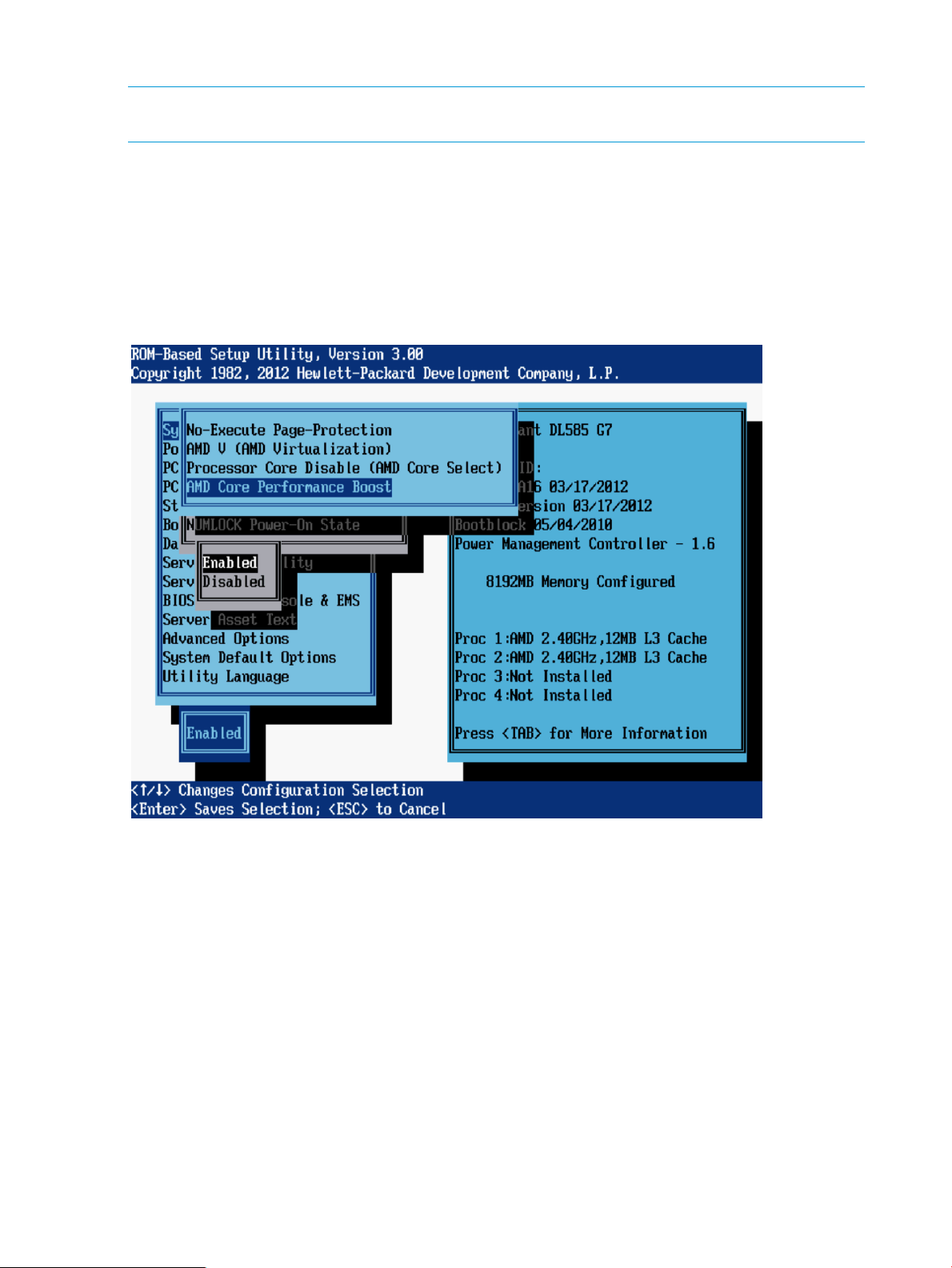
AMD Core Performance Boost
NOTE: This option is available on some servers with AMD processors. For more information, see
the documentation for your processor model.
If supported by your processor, AMD Core Performance Boost enables the processor to transition
to a higher frequency than the processor`s rated speed if the processor has available power
headroom and is within temperature specifications. Disabling this feature reduces power usage,
but also reduces the maximum achievable system performance under some workloads.
Options include:
• Enabled (default)
• Disabled
36 RBSU menu-driven interface, version 3.xx or later (G6, G7, and Gen8 servers)
Page 37

Intel VT-d
NOTE: This option is available on some servers with Intel processors. For more information, see
the documentation for your processor model.
When enabled, a Virtual Machine Manager supporting this feature can use hardware capabilities
provided by the Intel Virtualization Technology for Directed I/O.
Options include:
• Enabled (default)
• Disabled
System Options menu 37
Page 38
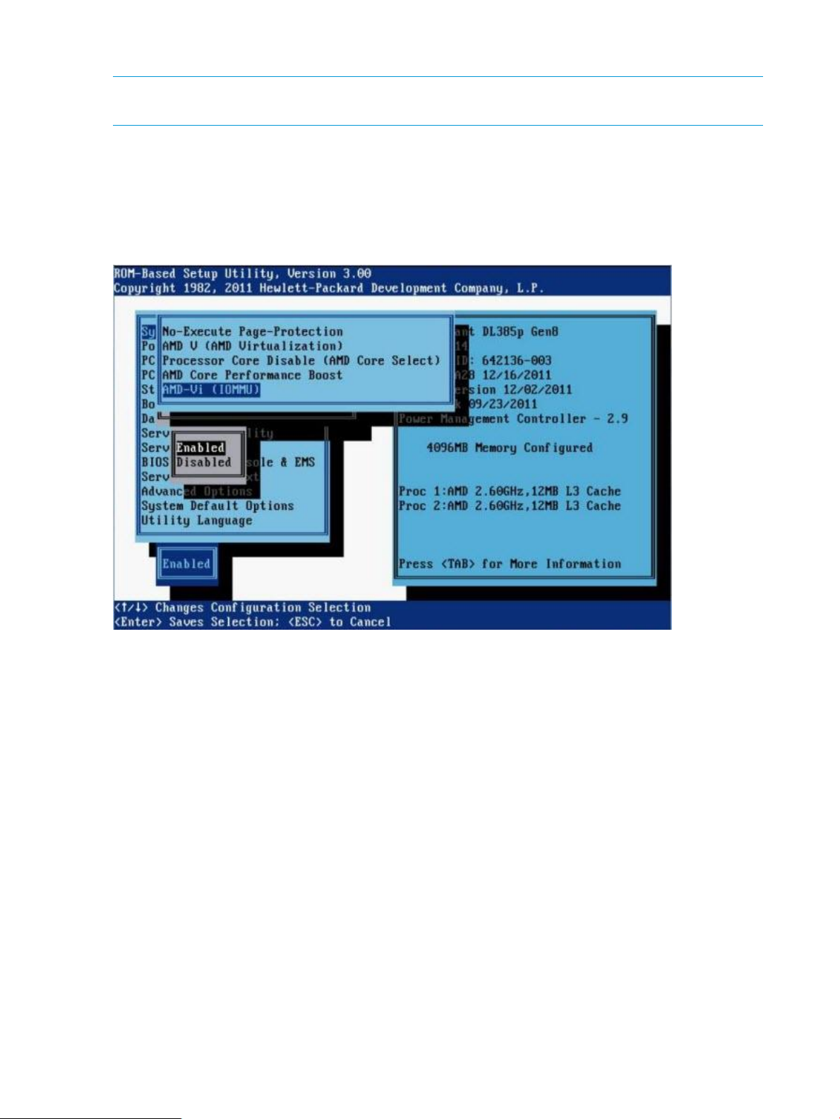
AMD-Vi (IOMMU)
NOTE: This option is available on some Gen8 servers with AMD processors. For more information,
see the documentation for your processor model.
When enabled, a Virtual Machine Manager supporting this feature can use hardware capabilities
provided by the AMD I/O Memory Management Unit (IOMMU).
Options include:
• Enabled (default)
• Disabled
38 RBSU menu-driven interface, version 3.xx or later (G6, G7, and Gen8 servers)
Page 39

Remote Console Mode
NOTE: This option is available only on HP ProLiant ws460c Blade Workstations. It is not available
on other server blades.
The Remote Console Mode option controls whether the system console image is displayed though
an embedded video controller or mezzanine graphics adapter.
Options include:
• User Mode—Video displays through the embedded video controller during POST, but switches
to the mezzanine graphics adapter for OS boot to display the Windows desktop. In this mode,
the Windows console can only be viewed using remote protocols (for example, using Microsoft
Remote Desktop Connection). Because the embedded video controller is inactive after the
operating system starts, the Windows desktop is not visible on the Local I/O Connector or
through iLO. The screen displays a message stating that the blade is in User Mode.
• Admin Mode—Video displays through the embedded video controller during POST and OS
boot. In this mode, the mezzanine graphics adapter is disabled.
In Admin Mode, the boot console and the Windows desktop generated by the embedded
video controller can be viewed by using one of the following:
◦ A monitor connected to the Local I/O Connector video signal
◦ The iLO Remote Console by pointing your browser to the iLO IP address
◦ Remote desktop connection
• Setup Mode—Video is displayed on the embedded video controller during POST and OS
boot. In this mode, the mezzanine graphics adapter is enabled. Setup Mode is similar to
Admin Mode, but in Setup Mode, both the embedded video controller and the mezzanine
graphics adapter are visible to the Windows operating system. Visibility of the mezzanine
graphics adapter enables the Windows operating system to install the mezzanine graphics
adapter driver.
In Setup Mode, the Windows desktop can be viewed by using:
◦ A monitor connected to the Local I/O Connector video signal
◦ The iLO Remote Console by pointing your browser to the iLO IP address
◦ Remote desktop connection.
• Server Mode—System reverts back to server operation, system and NIC ID's match that of a
server. In this mode, the embedded video controller generates the boot console during POST
and then generates the Windows desktop. The mezzanine graphics adapter is not visible to
any Windows operating systems and is not used.
In Server Mode, the boot console and the Windows desktop generated by the embedded
video controller can be viewed by using:
◦ A monitor connected to the Local I/O Connector video signal
◦ The iLO Remote Console by pointing your browser to the iLO IP address
◦ Remote desktop connection
System Options menu 39
Page 40

40 RBSU menu-driven interface, version 3.xx or later (G6, G7, and Gen8 servers)
Page 41

NUMLOCK Power-On State
NOTE: This option is not supported on blade servers.
The NUMLOCK Power-On State option is a toggle setting that enables or disables the power-up
state of the NUMLOCK key. When the NUMLOCK key is enabled, it is active when the machine
powers up.
Options include:
• On
• Off (default)
System Options menu 41
Page 42

SATA Controller Options (Gen8 servers with SATA controllers)
NOTE: These SATA controller options are not supported on BL460, BL465, and DL385 servers)
Depending on your server model, options may include:
• “Embedded SATA Configuration” (page 42)
• “Drive Write Cache” (page 43)
• “HP Smart Array B320i RAID Configuration” (page 44)
Embedded SATA Configuration
NOTE: This option is available only on server models that support Dynamic Smart Array. For
more information, see the HP Dynamic Smart Array RAID Controller User Guide on the HP website
(http://h20564.www2.hp.com/portal/site/hpsc/public/kb/docDisplay/?
docId=emr_na-c03326739).
This option configures the embedded SATA ports, either for optical drives or when connecting
SATA drives directly.
CAUTION:
• Changing this setting may result in data loss or data corruption on existing drives.
• Back up all drives before enabling this feature.
• Enable SATA AHCI support only after consulting the OS documentation to ensure that base
media drivers support this feature.
After the pressing any key to clear the warning, the following options are displayed:
• Enable SATA Legacy Support
• Enable SATA AHCI Support
The default setting for this option is dependent on the server model.
42 RBSU menu-driven interface, version 3.xx or later (G6, G7, and Gen8 servers)
Page 43

Drive Write Cache
IMPORTANT:
• This option is not visible if SATA SW RAID is enabled.
• Enabling Drive Write Cache may result in data loss or data corruption if an unexpected power
loss occurs.
Drive Write Cache controls the behavior of the Drive Write Cache in the ATA hard drive. This
feature provides greater drive performance.
After reading the warning message, press any key to display the following settings:
• Enabled (default)
• Disabled
System Options menu 43
Page 44

HP Smart Array B320i RAID Configuration
NOTE: This option is available only on server models that support Dynamic Smart Array. For
more information, see the HP Dynamic Smart Array RAID Controller User Guide on the HP website
(http://h20564.www2.hp.com/portal/site/hpsc/public/kb/docDisplay/?
docId=emr_na-c03326739).
IMPORTANT:
• Changing this setting may result in data loss or data corruption on existing drives.
• Back up all drives before enabling this feature.
This option controls HP Dynamic RAID support on the SAS controller (embedded or optionally
purchased on a daughter card).
After reading the warning message, press any key to display the following settings:
• Enabled
• Disabled
NOTE: The default setting for this option is dependent on the server model.
44 RBSU menu-driven interface, version 3.xx or later (G6, G7, and Gen8 servers)
Page 45

Power Management Options menu
The Power Management Options menu includes the following options:
• “HP Power Profile” (page 45)
• “HP Power Regulator” (page 46)
• “Redundant Power Supply Mode” (page 47)
• “Advanced Power Management Options” (page 48)
NOTE: When using the Intelligent Provisioning Quick Configs options available for Gen8 servers,
you can set a basic policy for performance versus power usage without having to configure
individual settings through RBSU menus. For more information, see “Intelligent Provisioning Quick
Configs settings and corresponding RBSU settings” (page 209).
HP Power Profile
This option enables the user to select the appropriate power profile based on power and
performance characteristics. The following options are available:
• Balanced Power and Performance (default)—Provides the optimum settings to maximize power
savings with minimal performance impact for most operating systems and applications.
• Minimum Power Usage—Enables power reduction mechanisms that may affect performance
negatively. This mode guarantees a lower maximum power usage by the system.
• Maximum Performance—Disables all power management options that may affect performance
negatively.
• Custom—Provides the opportunity to configure settings for your environment.
Power Management Options menu 45
Page 46

HP Power Regulator
This feature configures the Power Regulator for ProLiant support.
Options include:
• HP Dynamic Power Savings Mode (default)—Automatically varies processor speed and power
usage based on processor use, reduces overall power consumption with little or no impact to
performance, and does not require OS support.
• HP Static Low Power Mode—Reduces processor speed and power usage, guarantees a lower
maximum power usage for the system, and provides a high impact on performance in
environments with higher processor utilization.
• HP Static High Performance Mode—Processors run in the maximum power and performance
state, regardless of the OS power management policy.
• OS Control Mode—Processors run in the maximum power and performance state, unless the
OS enables a power management policy.
NOTE: Certain processors support only one power state and operate at their initialized frequency,
regardless of the Power Regulator setting.
After reading the note message, press any key to display the available settings.
46 RBSU menu-driven interface, version 3.xx or later (G6, G7, and Gen8 servers)
Page 47

Redundant Power Supply Mode
NOTE: This feature is not available on SL and BL server models.
This feature enables the user to configure how the system manages power delivery to power supplies
in redundant power supply configurations.
Options include:
• Balanced Mode (default)—Shares the power delivery between all installed power supplies.
NOTE: Power delivery may not be equal between all power supplies.
• High Efficiency Mode (Auto)—Delivers full power to one of the power supplies and places the
other power supplies on standby at a lower power-usage level. A semi-random distribution is
achieved, because the Auto option chooses between the odd or even power supply based
on the server's serial number.
• High Efficiency Mode (Odd Supply Standby)—Delivers full power to the even-numbered power
supplies and places the odd-numbered power supplies on standby at a lower power-usage
level.
• High Efficiency Mode (Even Supply Standby)—Delivers full power to the odd-numbered power
supplies and places the even-numbered power supplies on standby at a lower power-usage
level.
Power Management Options menu 47
Page 48

Advanced Power Management Options
Depending on your server model, options may include:
• “Intel QPI Link Power Management” (page 49)
• “Intel QPI Link Frequency” (page 50)
• “QPI Bandwidth Optimization (RTID)” (page 51)
• “Minimum Processor Idle Power Core State” (page 52)
• “Minimum Processor Idle Power Core C6 State” (page 53)
• “Minimum Processor Idle Power C1e State” (page 54)
• “Minimum Processor Idle Power Package State” (page 55)
• “Minimum Processor Idle Power State” (page 56)
• “Energy/Performance Bias” (page 57)
• “Maximum Memory Bus Frequency” (page 58)
• “Channel Interleaving” (page 59)
• “Memory Interleaving” (page 60)
• “PCI Express Generation 2.0 Support” (page 61)
• “PCIe Gen 3 Control (for select devices)” (page 62)
• “Maximum PCI Express Speed” (page 63)
• “Dynamic Power Savings Mode Response” (page 64)
• “Collaborative Power Control” (page 65)
• “Power Capping Support” (page 66)
• “ACPI SLIT Preferences” (page 67)
• “DIMM Idle Power Saving Mode” (page 68)
• “DIMM Voltage Preference” (page 69)
• “Memory Power Savings Mode” (page 70)
• “HyperTransport Frequency” (page 71)
• “Dynamic Power Capping Functionality” (page 72)
48 RBSU menu-driven interface, version 3.xx or later (G6, G7, and Gen8 servers)
Page 49
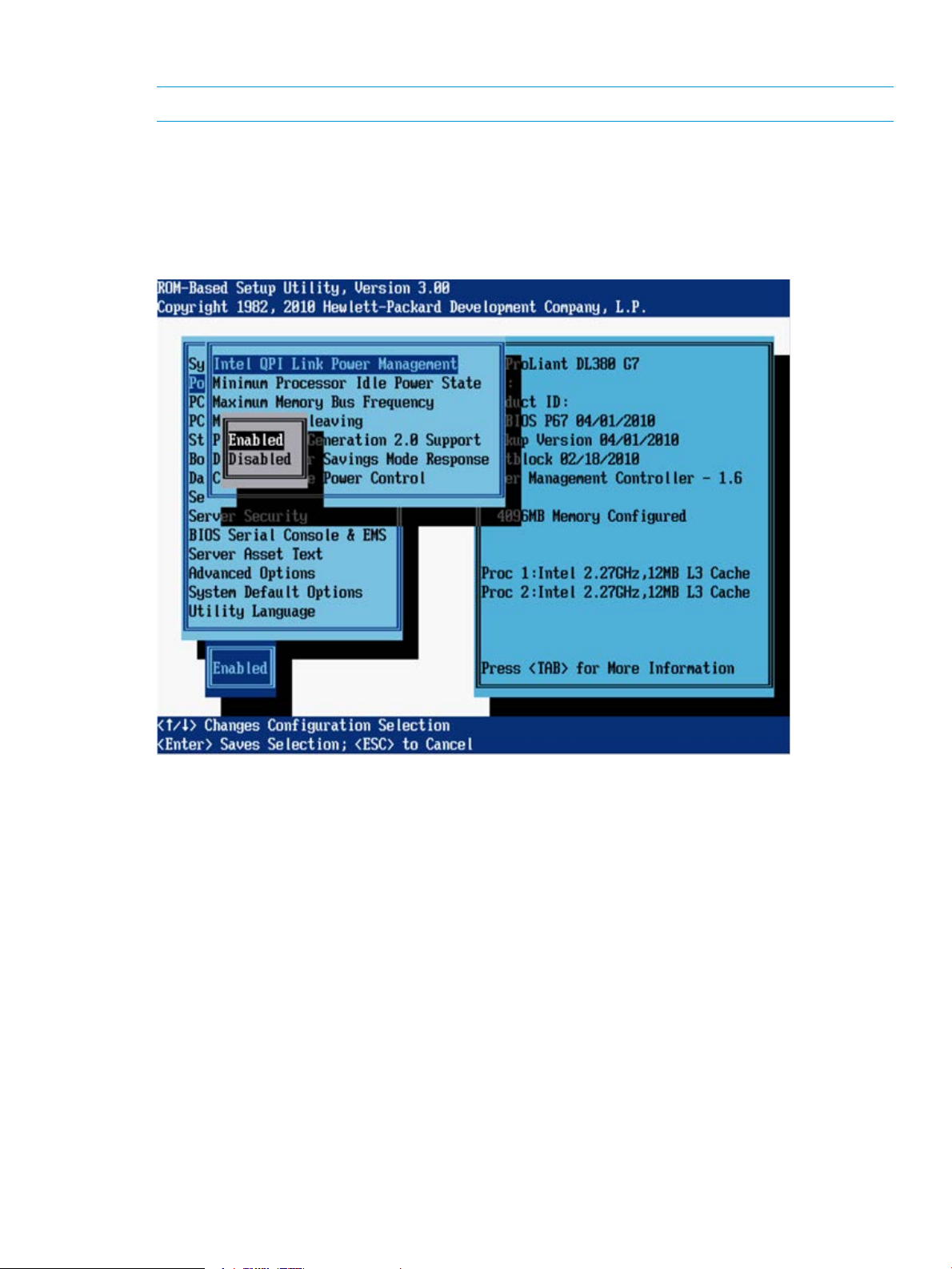
Intel QPI Link Power Management
NOTE: This option is available on servers with multiple Intel processors.
This feature places the Quick Path Interconnect links into a low power state when the links are not
being used. This reduces power usage with minimal performance impact.
Options include:
• Enabled (default)
• Disabled
Power Management Options menu 49
Page 50

Intel QPI Link Frequency
NOTE: This option is available on Gen8 servers with multiple Intel processors.
This option enables you to set the QPI Link frequency to a low speed. Running at a lower frequency
may reduce power consumption, but may also impact system performance.
Options include:
• Auto (default)
• Min QPI Speed
50 RBSU menu-driven interface, version 3.xx or later (G6, G7, and Gen8 servers)
Page 51
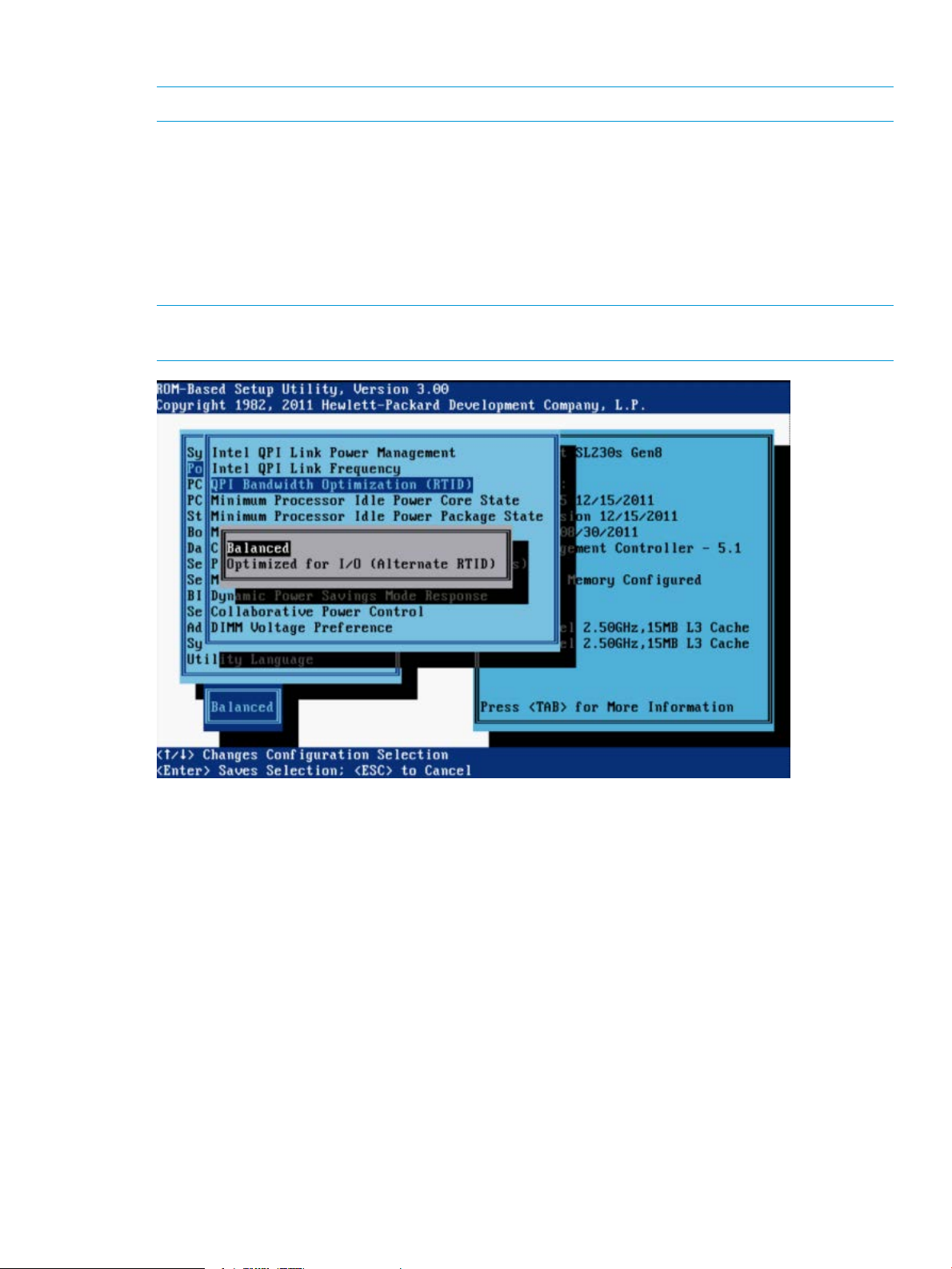
QPI Bandwidth Optimization (RTID)
NOTE: This option is available on Gen8 servers with Intel processors.
The QPI link between two processors has been tuned to provide the best performance for all known
applications.
Options include:
• Balanced (default)—Provides the best performance for nearly all conventional customer
applications and benchmarks.
• Optimized for I/O—Increases bandwidth from I/O devices such as GPUs that rely on direct
access to system memory. This setting can have a negative effect on system performance.
NOTE: Setting this option to Optimized for I/O can have a negative impact on memory and
system performance.
Power Management Options menu 51
Page 52

Minimum Processor Idle Power Core State
NOTE: This option is available on servers with Intel processors.
This feature selects the lowest processor idle power state (C-state) supported by the OS. The higher
the C-state, the lower the power usage of the idle power state. C6 is the lowest power idle state
supported by the processor.
Options include:
• C6 State (default)
• C3 State
• C1E State
• No C-states
52 RBSU menu-driven interface, version 3.xx or later (G6, G7, and Gen8 servers)
Page 53
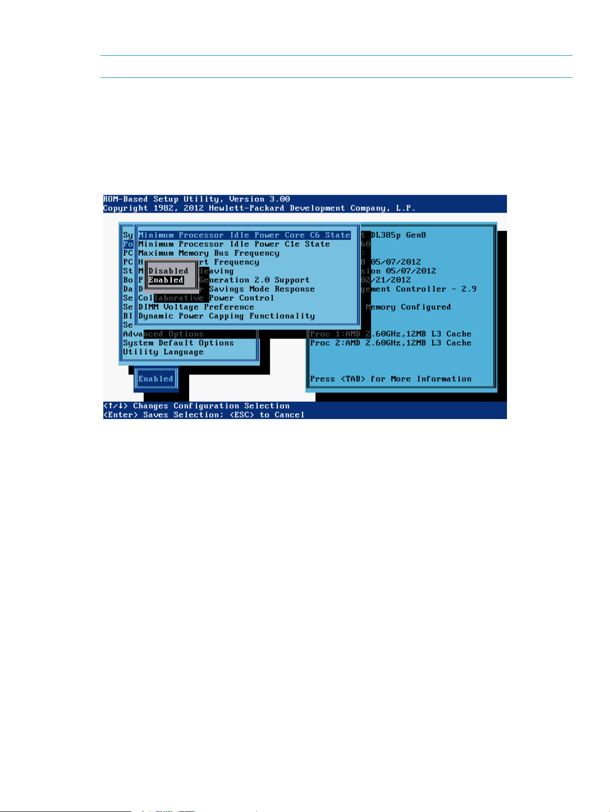
Minimum Processor Idle Power Core C6 State
NOTE: This option is available on Gen8 servers with AMD processors.
This option enables individual cores of a processor to enter C6 state when the operating system
requests a low power C-State. This state consumes less power and allows other cores in the processor
to enter a higher performance boost state.
Options include:
• Enabled (default)
• Disabled
Power Management Options menu 53
Page 54
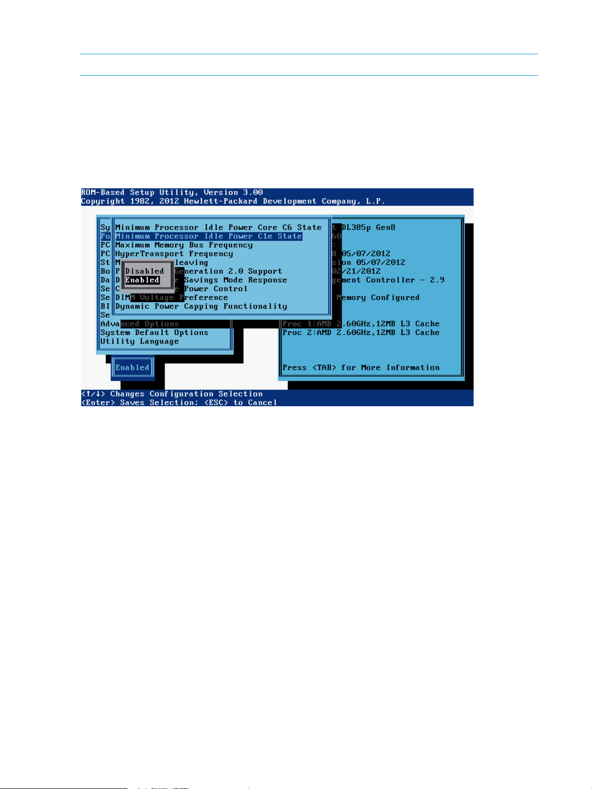
Minimum Processor Idle Power C1e State
NOTE: This option is available on Gen8 servers with AMD processors.
This option enables the processor to enter a reduced power C1e state when all cores of a processor
have entered a low power C-state. Enabling this feature results in substantial power savings in
most configurations.
Options include:
• Enabled (default)
• Disabled
54 RBSU menu-driven interface, version 3.xx or later (G6, G7, and Gen8 servers)
Page 55

Minimum Processor Idle Power Package State
NOTE: This option is available on servers with Intel processors.
This feature selects the lowest processor idle power state (C-state). The processor automatically
transitions into package C-states based on the Core C-states that cores on the processor have
transitioned to. The higher the package C-state, the lower the power usage of that idle package
state. Package C6 (non-retention) is the lowest power idle package state supported by the processor.
Options include:
• Package C6 State (On G7 and earlier servers) / Package C6 (retention) State (On Gen8
servers)
• Package C3 State (On G7 and earlier servers) (default) / Package C6 (non-retention) State
(On Gen8 servers)
• No Package State
Power Management Options menu 55
Page 56

Minimum Processor Idle Power State
NOTE: This option is available on G7 servers with AMD processors.
This feature selects the lowest processor idle power state (C-state) supported by the OS. The higher
the C-state, the lower the power usage of the idle power state. The lowest power idle state supported
by the processor is C6.
Options may include:
• C6 State (default)
• C3 State
• C1E State
• No C-states
NOTE: Available options and the system default may vary depending on server model.
56 RBSU menu-driven interface, version 3.xx or later (G6, G7, and Gen8 servers)
Page 57
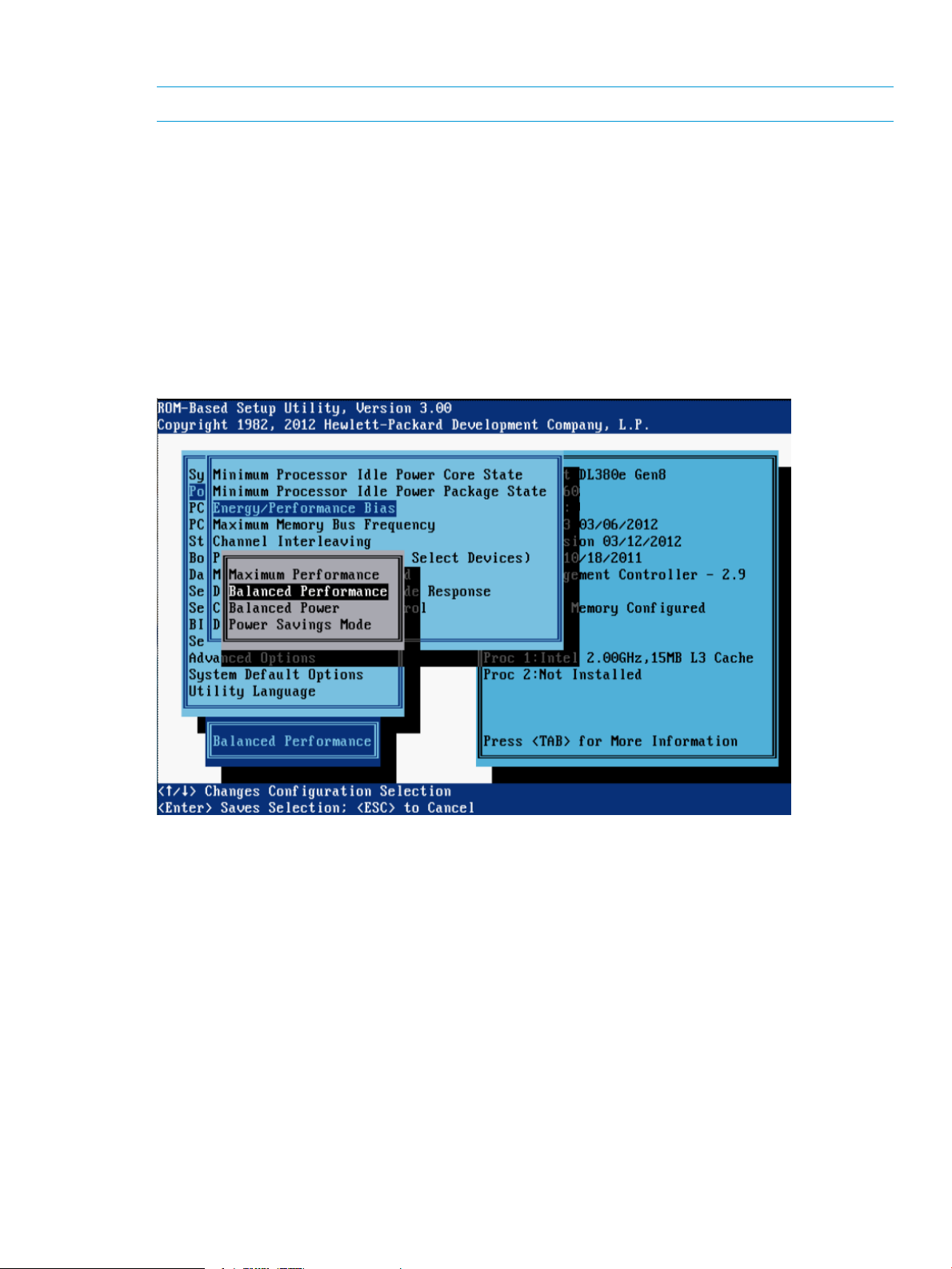
Energy/Performance Bias
NOTE: This option is available on Gen8 servers with Intel processors.
This option configures several processor subsystems to optimize processor performance and power
usage.
Options include:
• Maximum Performance—Provides the highest performance and lowest latency, but should be
used only in environments that are not sensitive to power consumption.
• Balanced Performance (default) — Provides the optimum balance between power efficiency
and performance and is recommended for most environments.
• Balanced Power—Provides optimum power efficiency based on server utilization.
• Power Savings Mode—Available for use in environments that are power sensitive and are
willing to accept reduced performance.
Power Management Options menu 57
Page 58

Maximum Memory Bus Frequency
This feature enables you to configure the system to run memory at a lower maximum speed than
what is supported by the installed processor and DIMM configuration. Setting this option to Auto
configures the system to run memory at the maximum speed supported by the system configuration.
Options include:
• Auto (default)
• 1333MHz
• 1066MHz
• 800MHz
NOTE: Options vary depending on the installed processor.
58 RBSU menu-driven interface, version 3.xx or later (G6, G7, and Gen8 servers)
Page 59

Channel Interleaving
NOTE: This option is available on servers with Intel processors.
This feature modifies the level of interleaving for the memory system configuration. Typically, higher
levels of memory interleaving result in maximum performance. However, reducing the level of
interleaving can result in power savings.
Options include:
• Enabled (default)
• Disabled
Power Management Options menu 59
Page 60

Memory Interleaving
This feature modifies the level of interleaving for the memory system configuration. Typically, higher
levels of memory interleaving result in maximum performance. However, reducing the level of
interleaving can result in power savings.
For AMD systems, the following options are available:
• No Interleaving
• Channel Interleaving (default)
For Intel systems, the following options are available:
• Full Interleaving (default)
• Channel Only Interleaving
• No Interleaving
60 RBSU menu-driven interface, version 3.xx or later (G6, G7, and Gen8 servers)
Page 61

PCI Express Generation 2.0 Support
NOTE: This option is available on servers with AMD processors.
This feature controls PCIe Generation 1 or PCIe Generation 2 support and can be used to reduce
system power usage. In addition, this feature can be used to work around issues with devices that
claim PCIe 2.0 support but do not adhere to the PCIe 2.0 specification.
Options include:
• Auto (default)
• Force PCI-E Generation 2
• Force PCI-E Generation 1
IMPORTANT: PCIe Generation 1 devices may not function properly when the PCI Express speed
is forced to PCIe Generation 2. Before changing this option, see the QuickSpecs and user
documentation for all expansion cards.
Power Management Options menu 61
Page 62

PCIe Gen 3 Control (for select devices)
NOTE: This option is available on Gen8 servers with Intel processors.
This option controls the maximum supported speed of individual PCI Express links for embedded
devices and for devices installed in PCIe slots. Enabling PCIe Generation 3 Control permits the
device to fun at full speed.
NOTE: This option works in conjunction with the Maximum PCI Express Speed option. When
setting the PCIe Generation 3 Control to Enabled, the Maximum PCI Express Speed option must
be set to Maximum Supported. For more information about the Maximum PCI Express Speed
option, see “Maximum PCI Express Speed” (page 63).
After selecting the embedded device or PCIe slot to configure, the following options are presented:
• Enabled (default)
• Disabled
62 RBSU menu-driven interface, version 3.xx or later (G6, G7, and Gen8 servers)
Page 63

Maximum PCI Express Speed
NOTE: This option is available on Gen8 servers with Intel processors.
This option enables lowering the maximum PCIe speed at which the server allows PCIe devices to
operate and may be useful in addressing issues with problematic PCIe devices. If a PCIe device
does not run properly at its design speed, lowering the speed in which the device is running may
address the problem.
NOTE: This option works in conjunction with the PCIe Gen 3 Control setting. When setting the
PCIe Gen 3 Control to Enabled, this Maximum PCI Express Speed option must be set to Maximum
Supported. For more information about the PCIe Gen 3 Control settings, see “PCIe Gen 3 Control
(for select devices)” (page 62).
Options include:
• Maximum Supported (default)—Configures the platform to run at the maximum speed supported
by the platform or the PCIe device (whichever is lower).
• PCIe Generation 1.0—Configures the platform to run at the lowest speed possible in the PCIe
links, which is PCIe Generation 1.0. When setting this option to PCIe Generation 1.0,
performance of high-end cards such as 10GbE NIC Cards and I/O Accelerators may be
affected.
Power Management Options menu 63
Page 64

Dynamic Power Savings Mode Response
The Dynamic Power Savings Mode Response feature enables the System ROM to control processor
performance and power state depending on the processor workload. This option configures the
response time for switching between these states.
Options include:
• Fast (default)—Optimal for workloads that require a low latency response to an increase in
processor demand.
• Slow—Optimal for workloads where a longer latency response to increased processing
demand is an acceptable tradeoff for reduced power consumption. Depending on the processor
workload, selecting this option may negatively impact performance.
64 RBSU menu-driven interface, version 3.xx or later (G6, G7, and Gen8 servers)
Page 65

Collaborative Power Control
NOTE: This option is available on G7 and Gen8 servers with Intel processors and on Gen8
servers with AMD processors.
For operating systems that support the Processor Clocking Control Interface (PCCI), enabling this
option allows the operating system to request processor frequency changes even when the server
has the Power Regulator option configured for Dynamic Power Savings Mode. For operating
systems that do not support the PCC Interface or when the Power Regulator is not configured for
Dynamic Power Savings Mode, this option has no impact on system operation.
Options include:
• Enabled (default)
• Disabled
Power Management Options menu 65
Page 66

Power Capping Support
NOTE: This option is available on Gen8 servers with Intel processors.
This option applies power cappings if configured via iLO.
Options include:
• Enabled (default)
• Disabled
66 RBSU menu-driven interface, version 3.xx or later (G6, G7, and Gen8 servers)
Page 67

ACPI SLIT Preferences
NOTE: This option is available on Gen8 servers with Intel processors.
ACPI SLIT (System Locality Information Table) describes the relative access times between processors,
memory subsystems, and I/O subsystems. Operating systems that support SLIT can improve
performance by allocating resources and workloads more efficiently.
Options include:
• Enable
• Disable (default)
Power Management Options menu 67
Page 68

DIMM Idle Power Saving Mode
NOTE: This option is available on select G7 servers.
The DIMM Idle Power Saving Mode option provides the capability to enable or disable power
throttling for the DIMMs installed in the system. Enabling this option allows DIMMs that support
idle power saving features to enter a low power mode when idle. In some applications, this can
reduce overall system power consumption, but may also slightly reduce overall memory performance
due to the increased latency associated with transitions into and out of idle power saving mode.
When disabled, this option prevents installed DIMMs from entering a lower power mode when
idle. Be sure that all installed DIMMs support DIMM idle power saving features before selecting
the Enabled option. Such support has been verified for all HP DIMMs supported on these platforms.
Options include:
• Enabled (default)
• Disabled
68 RBSU menu-driven interface, version 3.xx or later (G6, G7, and Gen8 servers)
Page 69
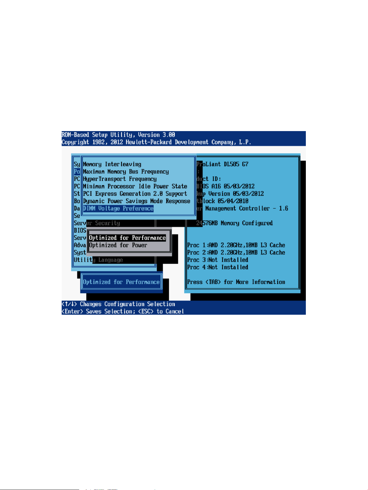
DIMM Voltage Preference
Gen8 systems support both LV-DIMMs (1.35V) and 1.5V-only DIMMs. LV-DIMMs can switch to
1.5V capacity in turbo mode. At 1.35V, they can match the performance of 1.5V DIMMs in most
situations, but in some limited configurations, must switch to 1.5V for maximum speed.
Options include:
• Optimized for Performance (default)—This sets the voltage for a system with all low voltage
DIMMs to 1.5V only if that provides a performance advantage. Otherwise, the DIMMs are
left at 1.35V.
• Optimized for Power—Low voltage DIMMs run at 1.35V, even if this requires memory to run
at a lower frequency. The system does not allow 1.35V operation unless all installed DIMMs
in the system are low voltage DIMMs.
Power Management Options menu 69
Page 70

Memory Power Savings Mode
This option configures several memory parameters to optimize memory performance and power
usage.
Options include:
• Balanced (default)—Provides optimum power efficiency. Recommended for most environments.
• Maximum Performance —Provides optimum memory performance. This setting should be used
in environments that require the highest performance and/or lowest latency, but are not
sensitive to power consumption.
70 RBSU menu-driven interface, version 3.xx or later (G6, G7, and Gen8 servers)
Page 71

HyperTransport Frequency
NOTE: This option is available on servers with AMD processors.
This option enables you to select the operating speed of the HyperTransport link. Running in HT
power savings mode may result in lower power consumption but may impact overall system
performance.
Power Management Options menu 71
Page 72

Dynamic Power Capping Functionality
NOTE: This option is available on Gen8 servers.
This option controls whether the System ROM Power Calibration is run during the boot process.
Options include:
• Enabled (default)—The System ROM Power Calibration is executed during the boot process.
• Disabled—The System ROM Power Calibration will not be executed during the boot process.
Boot time will be faster, but you will no longer be able to configure Dynamic Power Capping
via iLO.
72 RBSU menu-driven interface, version 3.xx or later (G6, G7, and Gen8 servers)
Page 73

PCI IRQ Settings menu
These PCI IRQ options configure the legacy IRQ for embedded and slot-based PCI/PCIe devices.
Multiple devices can share one IRQ.
To change the IRQ assignment for a device, highlight the device and press the Enter key. A menu
is displayed with options to change the IRQ and disable the device.
PCI IRQ Settings menu 73
Page 74

PCI Device Enable/Disable menu
These options enable and disable embedded and add-in devices. Disabling devices reallocates
the resources (memory, I/O, and, in some cases, option ROM space and power) that would
normally be allocated to the device.
By default, all devices are Enabled.
NOTE: Only IRQs that are modified in RBSU retain the change during the next reboot. IRQs on
PCI devices that have not been modified are subject to change during reboot.
74 RBSU menu-driven interface, version 3.xx or later (G6, G7, and Gen8 servers)
Page 75

Standard Boot Order (IPL) menu
The Standard Boot Order (IPL) option configures the Initial IPL device and controls the search order
the server uses to look for a bootable device.
NOTE: If you enable or disable a device, restart the server. Changes do not take effect until after
reboot.
The following table describes devices and their default boot order settings.
Default boot order settingDevice
Set the IPL Device Boot Order to 1IPL:1 CD-ROM
Set the IPL Device Boot Order to 2IPL:2 Floppy Drive (A :)
Set the IPL Device Boot Order to 3IPL:3 USB Drive Key (C :)
Set the IPL Device Boot Order to 4IPL:4 Hard Drive C :
Set the IPL Device Boot Order to 5IPL:5 PCI Embedded Adapter Port 1
Standard Boot Order (IPL) menu 75
Page 76

Boot Controller Order menu
The Boot Controller Order option selects which of the installed mass storage device controllers is
used as the primary boot controller. The server attempts to boot the drives attached to each storage
controller in the order presented in this list.
By default, the primary boot controller is set to controller 1.
NOTE: Changes made to the Boot Controller Order in the ORCA Utility are reflected in this menu.
For more information about ORCA, see the Configuring Arrays on HP Smart Array Controllers
Reference Guide on the HP website (http://h20564.www2.hp.com/portal/site/hpsc/public/kb/
docDisplay/?docId=emr_na-c00729544).
IMPORTANT: PCI devices that have been disabled in the PCI Devices menu might still be visible
on the Boot Controller Order screen.
76 RBSU menu-driven interface, version 3.xx or later (G6, G7, and Gen8 servers)
Page 77

Date and Time menu
The Date and Time option sets the system time and date. Enter the date in a month-day-year
(mm-dd-yyyy) format. Enter the time in an hour-minute-second (hh:mm:ss) format.
Date and Time menu 77
Page 78

Server Availability menu
The Server Availability menu includes options that configure the Automatic Server Recovery (ASR)
features:
• “ASR Status” (page 78)
• “ASR Timeout” (page 79)
• “Thermal Shutdown” (page 80)
• “Wake-On LAN” (page 81)
• “POST F1 Prompt” (page 82)
• “Power Button” (page 172)
• “Automatic Power-On (G7 servers)” (page 84)
• “Automatic Power-On (Gen8 servers)” (page 85)
• “Power-On Delay” (page 86)
ASR Status
The ASR Status option is a toggle setting that either enables or disables ASR (Automatic Server
Recovery).
Options include:
• Enabled (default)
• Disabled
78 RBSU menu-driven interface, version 3.xx or later (G6, G7, and Gen8 servers)
Page 79

ASR Timeout
The ASR Timeout option sets a timeout limit for resetting an unresponsive server. When the server
has not responded in the selected amount of time, the server automatically resets. The following
time increments are available:
• 10 Minutes (default)
• 15 Minutes
• 20 Minutes
• 30 Minutes
• 5 Minutes
Server Availability menu 79
Page 80

Thermal Shutdown
The Thermal Shutdown option is a toggle setting that determines when the server automatically
powers down due to dangerous temperatures.
Options include:
• Enabled (default)—The Advanced System Management driver initiates a graceful system
shutdown when the temperature reaches a critical level.
• Disabled—The Advanced System Management driver ignores thermal events and abruptly
shuts down the system when the temperature reaches a critical level.
80 RBSU menu-driven interface, version 3.xx or later (G6, G7, and Gen8 servers)
Page 81

Wake-On LAN
The Wake-On LAN option is a toggle setting that enables or disables the Wake-On LAN feature.
When enabled, the server can be powered up remotely using a network controller.
IMPORTANT: When enabling Wake-On LAN, be sure to remove all power cords before adding
or removing any adapters. Some adapters cause the system to power on when they are added or
removed.
After reading the note message, press any key to display the following settings:
• Enabled
• Disabled
NOTE: The default setting varies, depending on the server model.
Server Availability menu 81
Page 82
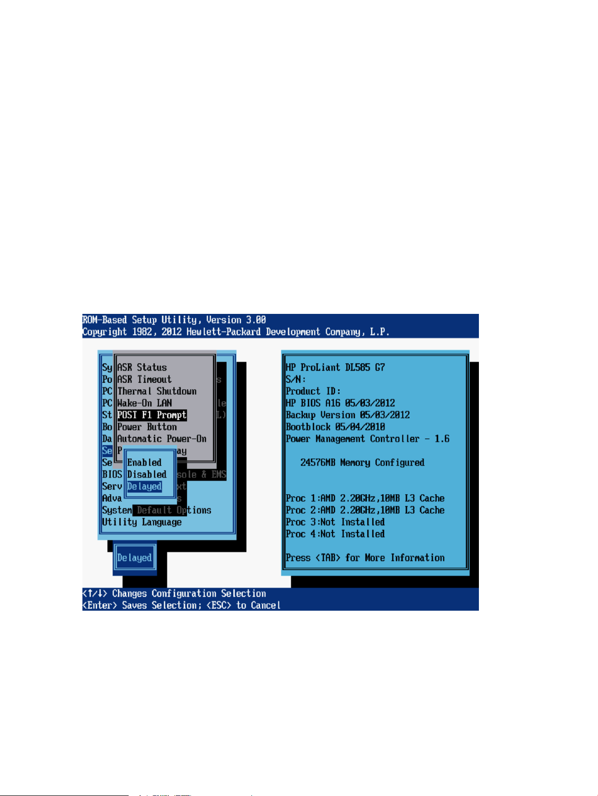
POST F1 Prompt
The POST F1 Prompt option is a toggle setting that configures the server so the F1 key must be
pressed to proceed when an error occurs during the power-up sequence. A series of system tests
execute during POST, with errors handled in one of the following ways:
• If errors occur that allow the system to continue operating, the system continues to boot but
posts a message.
• If critical components fail or are missing, the server attempts to boot. If it can boot, it posts a
message and an F1 prompt.
• If the system cannot run with the missing or failed components, it halts until those components
are replaced.
Options include:
• Enabled—If an error occurs during startup, the system stops at the F1 prompt. Boot continues
only after the F1 key is pressed.
• Disabled—If an error occurs during startup, the F1 prompt is not displayed and the system
continues to boot the OS.
• Delayed (default)—If an error occurs during startup, the system pauses for 20 seconds at the
F1 prompt and then continues to boot the OS.
82 RBSU menu-driven interface, version 3.xx or later (G6, G7, and Gen8 servers)
Page 83

Power Button
The Power Button option is a toggle setting that enables or disables the momentary power button.
NOTE: This Power Button feature does not override the 4-second hold-down of the physical server
power button.
Options include:
• Enabled (default)
• Disabled
Server Availability menu 83
Page 84
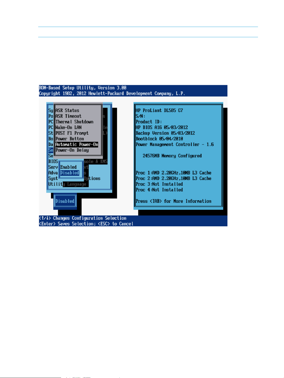
Automatic Power-On (G7 servers)
NOTE: This option is not available for blade servers.
The Automatic Power-On feature enables the server to automatically power on when auxiliary
power is applied to the server.
Options include:
• Enabled
• Disabled (default)
84 RBSU menu-driven interface, version 3.xx or later (G6, G7, and Gen8 servers)
Page 85
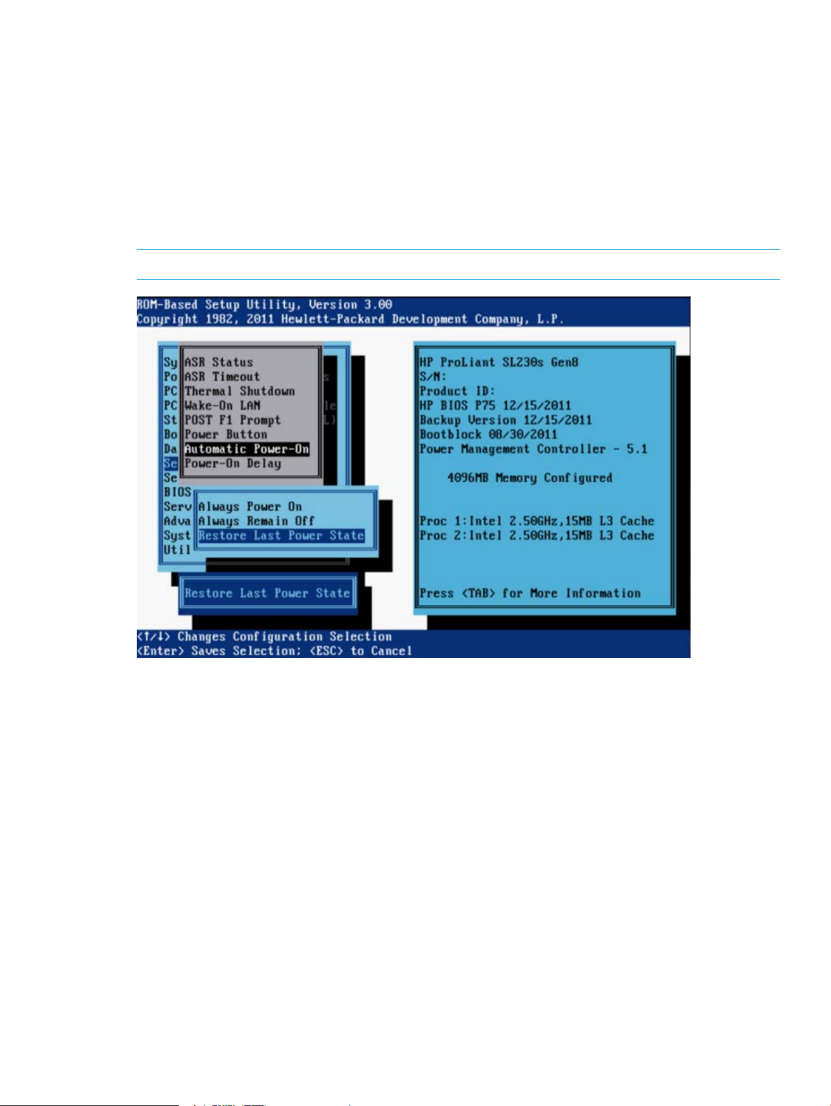
Automatic Power-On (Gen8 servers)
This feature determines the power state to achieve when power returns to a system that had
experienced an unexpected power outage. Options include:
• Always Power On—The system returns to the On state when AC power is restored, even if
the system had been in the Off state when power was lost.
• Always Remain Off—The system returns to the Off state when AC power is restored, even if
the system had been in the On state when power was lost.
• Restore Last Power State—The system returns to the previous power state (On or Off) when
AC power is restored.
NOTE: Available options and default values vary depending on server model.
Server Availability menu 85
Page 86

Power-On Delay
When multiple servers power up after a power loss, the Power-On Delay feature allows you to
delay the server from powering on, to prevent power usage spikes. Pressing the power button,
Wake-on LAN, RTC wake-up, and iLO Virtual Power Button events override any delay setting and
immediately power on the server.
Depending on the system, options may include:
• No Delay (default)
• Random Delay (up to two minutes)
• 15 Second Delay
• 30 Second Delay
• 45 Second Delay
• 60 Second Delay
86 RBSU menu-driven interface, version 3.xx or later (G6, G7, and Gen8 servers)
Page 87
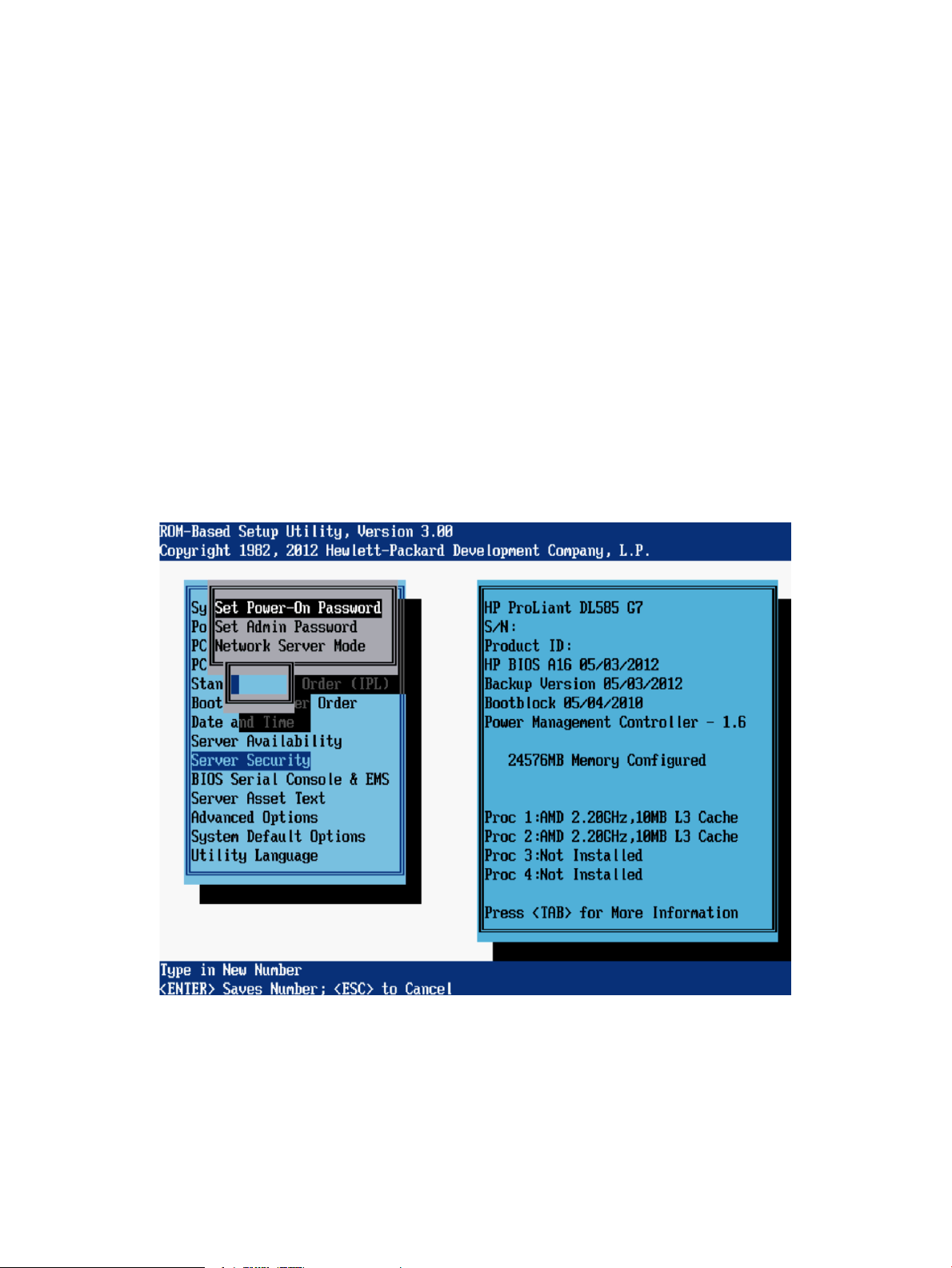
Server Security menu
The Server Security menu includes options that control access to the server and its utilities:
• “Set Power-On Password” (page 87)
• “Set Admin Password” (page 88)
• “Network Server Mode” (page 89)
• “Intelligent Provisioning (F10 Prompt)” (page 90)
• “Trusted Platform Module” (page 91)
Set Power-On Password
The Set Power-On Password option sets a password that controls access to the server during
power-up. The server cannot be powered up until the correct password is entered. To disable or
clear the password, enter the password followed by a / (slash) when prompted to enter the
password. To disable or clear the password, enter the password followed by a / (slash) when
prompted to enter the password.
Password requirements:
• Seven characters maximum.
• Can be any combination of numbers, letters, and special characters.
Server Security menu 87
Page 88
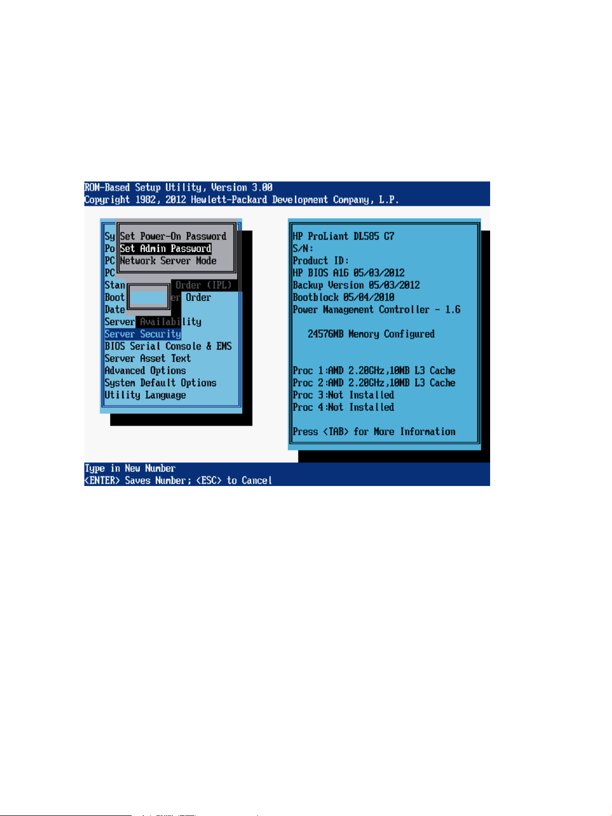
Set Admin Password
The Set Admin Password option sets a password to control access to the RBSU and the System
Maintenance Menu during POST. If set, this password must be entered when F9 or F10 is pressed
during POST. To disable or clear the password, enter the password followed by a / (slash) when
prompted to enter the password.
Password requirements:
• Seven characters maximum.
• Can be any combination of numbers, letters, and special characters.
88 RBSU menu-driven interface, version 3.xx or later (G6, G7, and Gen8 servers)
Page 89

Network Server Mode
NOTE: This option is available on HP ProLiant DL360 G7, DL380 G7, and DL585 G7 servers.
Gen8 servers do not support Network Server Mode.
The Network Server Mode option is a toggle setting that sets the server to operate in network server
mode. This feature works in conjunction with the power-on password.
When set to Disabled, the server operates normally. When it is set to Enabled, the following actions
occur:
• The local keyboard remains locked until the power-on password is entered.
• The power-on password prompt is bypassed.
• When a diskette is in the diskette drive, the server does not start unless the power-on password
is entered locally.
Options include:
• Enabled—Disables the server keyboard port.
• Disabled (default)
IMPORTANT: Network server mode cannot be enabled until the power-on password has been
established.
Server Security menu 89
Page 90

Intelligent Provisioning (F10 Prompt)
NOTE: This option is available on Gen8 servers.
This option controls access to Intelligent Provisioning. When disabled, this option prevents the user
from entering the Intelligent Provisioning environment. This option must be enabled to use Intelligent
Provisioning functionality.
The following methods for accessing Intelligent Provisioning are affected by this RBSU setting:
• During the server startup process, by pressing F10 when prompted.
• In the BIOS Serial Console, by pressing ESC+0 when prompted.
• In the Boot Menu, by selecting the option for a One Time Boot to Intelligent Provisioning.
Options include:
• Enabled (default)—All methods for accessing Intelligent Provisioning are enabled.
• Disabled—All methods for accessing Intelligent Provisioning are disabled. The prompts are
displayed, but the message indicates that the Intelligent Provisioning function is disabled.
90 RBSU menu-driven interface, version 3.xx or later (G6, G7, and Gen8 servers)
Page 91

Trusted Platform Module
For servers configured with an optional TPM, the following configuration options are available:
• “TPM Functionality” (page 91)
• “TPM Visibility” (page 92)
• “TPM Expansion ROM Measuring” (page 93)
• “TPM Clear” (page 94)
IMPORTANT: TPM menus appear only if the TPM kit is installed.
TPM Functionality
This option controls Trusted Platform Module functionality at startup. Options include:
• Enabled—Enables the TPM and BIOS secure startup. The TPM is fully functional in this mode.
• Disabled (default)—Disables the BIOS secure startup but still allows the TPM to be visible to
the operating system. The TPM functionality is limited, but can respond to most commands in
this mode. Selecting Disabled may prevent the server from booting to a TPM-aware operating
system.
CAUTION: A TPM locks all data access if proper procedures are not followed for modifying the
server, including: updating system or option firmware, replacing hardware such as the system
board and hard drive, or modifying TPM OS settings.
For information on installing and enabling the TPM module option, see the user documents for your
server model and the Data security in HP ProLiant servers using the Trusted Platform Module and
Microsoft Windows BitLocker Drive Encryption white paper: http://h20564.www2.hp.com/portal/
site/hpsc/public/kb/docDisplay/?docId=emr_na-c01681891.
Server Security menu 91
Page 92

TPM Visibility
The TPM Visibility option provides the ability to hide the TPM from the operating system. Options
include:
• Hide—BIOS secure startup is disabled and the TPM does not respond to any commands from
• Unhide (default)—The TPM is visible to the operating system.
any software. Hiding the TPM may prevent the server from booting to a TPM-aware operating
system. This option is intended to be used to remove the TPM feature from the system without
removing the actual hardware.
92 RBSU menu-driven interface, version 3.xx or later (G6, G7, and Gen8 servers)
Page 93

TPM Expansion ROM Measuring
TPM Expansion ROM Measuring enables the BIOS to measure the optional PCI or PCIe expansion
ROM code and store that measurement in the TPM. On subsequent reboots, operating systems or
validation software applications that utilize the measurements stored in the TPM can use this data
to detect modifications to PCI or PCIe expansion ROM versions. Options include:
• Enabled
• Disabled (default)
Server Security menu 93
Page 94

TPM Clear
The TPM Clear option allows the user to reset the TPM to factory settings, clearing any assigned
passwords, keys, or ownership data. Options include:
• Yes, Select to Clear
• No, Abort Clear (default)
IMPORTANT: Clearing the TPM may prevent the server from booting to a TPM-aware operating
system.
94 RBSU menu-driven interface, version 3.xx or later (G6, G7, and Gen8 servers)
Page 95

BIOS Serial Console & EMS menu
NOTE: Some languages or characters may require a specific emulation mode.
Through BIOS Serial Console and EMS console redirection, you can view POST error messages
and run RBSU remotely through a serial connection to the server COM port or iLO Virtual Serial
port. The remote server does not require a keyboard or mouse.
For more information about the BIOS Serial Console, see “RBSU BIOS Serial Console (CLI)”
(page 189).
The following menu options are available:
• “BIOS Serial Console Port” (page 96)
• “BIOS Serial Console Baud Rate” (page 97)
• “EMS Console” (page 98)
• “BIOS Interface Mode” (page 99)
BIOS Serial Console & EMS menu 95
Page 96
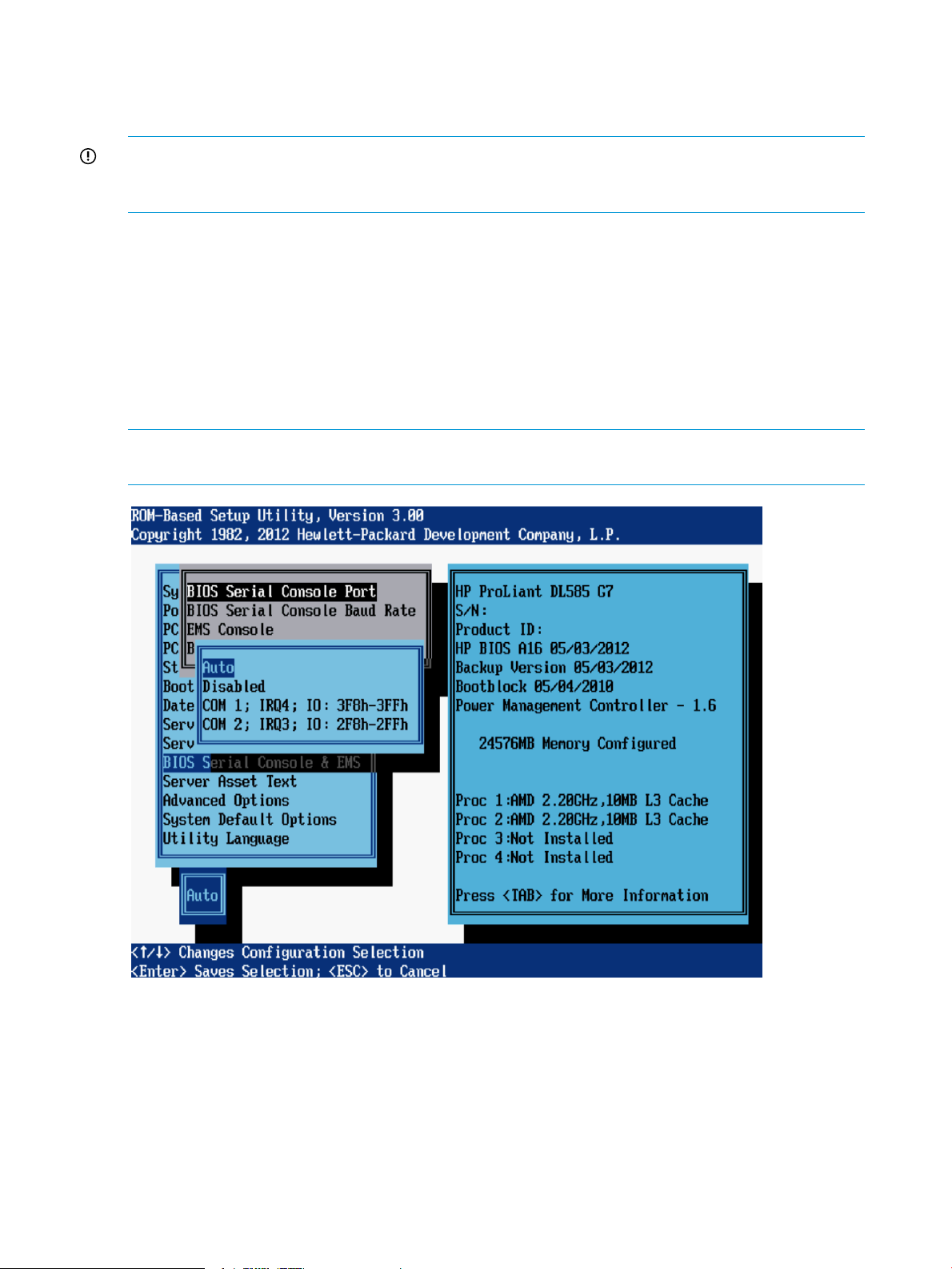
BIOS Serial Console Port
This BIOS Serial Console Port feature controls if and how video and keystrokes are redirected
through the serial port prior to OS startup.
IMPORTANT: This feature may interfere with non-terminal devices attached to the serial port. In
this case, disable the BIOS Serial Console. This feature is not supported under RBSU on Japanese
systems.
Options include:
• Auto (default for newer servers)—The server checks for the presence of a VT100 compatible
client running at 9600 Baud connected to the server and automatically enables the BIOS
Serial Console if one is found. This eliminates the need to run RBSU with a local keyboard
and monitor attached to enable the BIOS Serial Console feature.
• Disabled (default for older servers)
• COM 1
• COM 2
NOTE: Connect a null modem cable to the serial port/COM port on which BIOS Serial Console
is enabled.
96 RBSU menu-driven interface, version 3.xx or later (G6, G7, and Gen8 servers)
Page 97
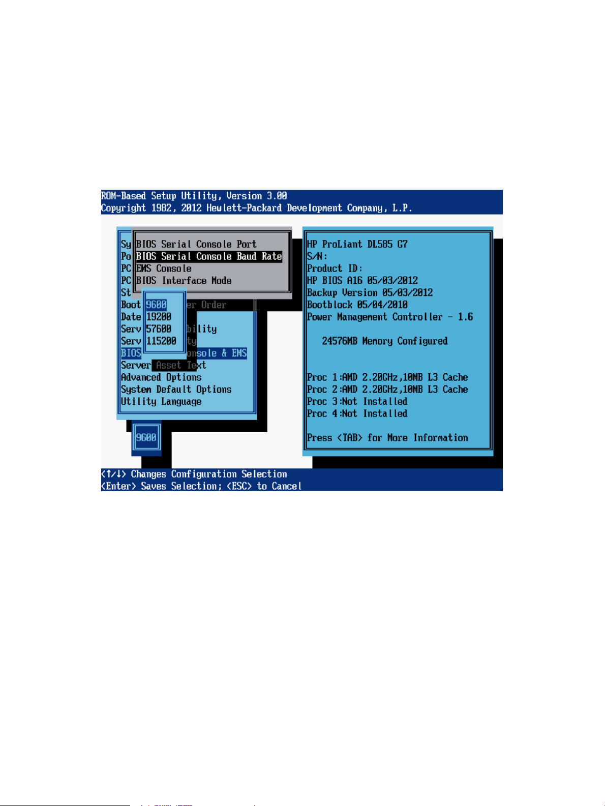
BIOS Serial Console Baud Rate
The BIOS Serial Console Baud Rate option controls transfer rate at which data is transmitted through
the serial port.
Options include:
• 9600 (default)
• 19200
• 57600
• 115200
BIOS Serial Console & EMS menu 97
Page 98
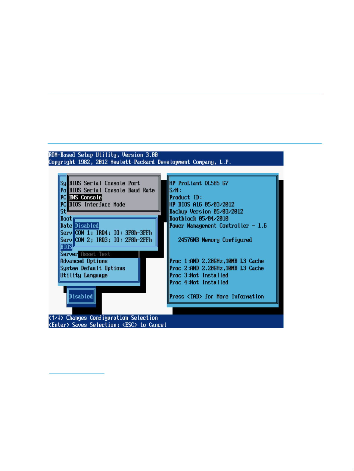
EMS Console
The EMS Console option is a Microsoft Windows Server 2003 feature that enables the Emergency
Management Console to be redirected through a specified serial port.
Options include:
• Disabled (default for all servers except blades)
• COM1 (default for blade servers)
• COM2
NOTE:
• When using iLO, select the value assigned to the Virtual Serial Port (“Virtual Serial Port”
(page 14)).
• When redirecting EMS through a physical serial port, select the value assigned to the Embedded
Serial Port (“Embedded Serial Port” (page 12)).
EMS provides input/output support for all Microsoft Windows kernel components: the loader,
setup, recovery console, OS kernel, blue screens, and the Special Administration Console. The
Special Administration Console is a text mode management console available after Windows
Server 2003 OS has initialized. For more information on EMS, go to the Microsoft website
(www.microsoft.com).
Microsoft enables EMS in the OS, but EMS must also be enabled in the ROM. When enabled,
EMS assumes the serial port for redirection and may cause interference with other devices attached
to the serial port. To avoid interference, EMS is disabled in the system ROM by default on HP
ProLiant ML and DL servers. If EMS is disabled in Windows Server 2003, perform the following
steps to update the boot.ini file:
1. Enable EMS in RBSU.
2. Run bootcfg/ems on/id 1.
3. Reboot.
98 RBSU menu-driven interface, version 3.xx or later (G6, G7, and Gen8 servers)
Page 99
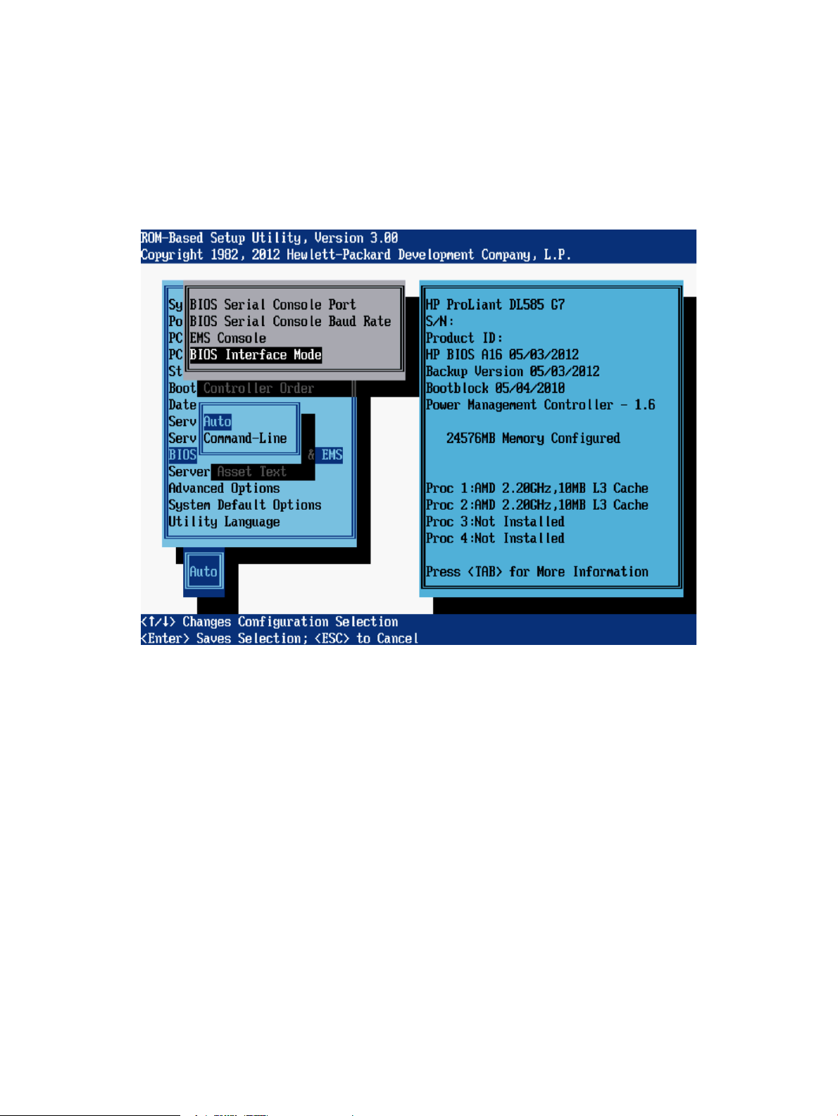
BIOS Interface Mode
This BIOS Interface Mode option determines whether the menu-driven mode or the command line
interface mode is displayed for ROM-based utilities.
Options include:
• Auto (default)—Enables CLI mode automatically for ROM embedded utilities, if the system
detects a console connection through the serial port instead of the keyboard.
• Command-Line—CLI mode is always enabled for ROM embedded utilities.
BIOS Serial Console & EMS menu 99
Page 100

Server Asset Text menu
The Server Asset Text menu includes options that customize the system-specific text for the server.
The following menu options are available:
• “Server Info Text” (page 100)
• “Administrator Info Text” (page 101)
• “Service Contact Text” (page 102)
• “Custom POST Message” (page 103)
Server Info Text
These options define reference information for the server administrator, which is displayed in Insight
Manager.
• Server Name—Identifies the server.
• Server Asset Tag—Identifies the server asset number.
• Server Primary OS—Describes the primary OS of the server.
• Other Text—Additional text describing the server.
NOTE: Each of these options can display a maximum of 14 characters. By default, all values
are blank.
100 RBSU menu-driven interface, version 3.xx or later (G6, G7, and Gen8 servers)
 Loading...