

Page 1

HP R3000v UPS
User Guide
Page 2

© Copyright 2008 Hewlett-Packard Development Company, L.P.
The information contained herein is subject to change without notice. The only warranties for HP products and
services are set forth in the express warranty statements accompanying such products and services. Nothing
herein should be construed as constituting an additional warranty. HP shall not be liable for technical or
editorial errors or omissions contained herein.
Audience assumptions
This guide is for the person who operates, configures, maintains, and troubleshoots UPSs. HP
assumes you are qualified in the servicing of high-voltage equipment and trained in recognizing
hazards in products with hazardous energy levels.
Page 3
Class A EMC Statements
EN 62040-2
Some configurations are classified under EN 62040-2 as “Category C2 UPS.” For these configurations, the following applies:
WARNING This is a category C2 UPS product. In a residential environment, this product may cause radio interference, in which case the
user may be required to take additional measures.
Special Symbols
The following are examples of symbols used on the UPS or accessories to alert you to important information:
RISK OF ELECTRIC SHOCK - Observe the warning associated with the risk of electric shock symbol.
CAUTION: REFER TO OPERATOR’S MANUAL - Refer to your operator’s manual for additional
information, such as important operating and maintenance instructions.
This symbol indicates that you should not discard the UPS or the UPS batteries in the trash. This product contains
sealed, lead-acid batteries and must b e disposed of properly. For more information, contact your local
recycling/reuse or hazardous waste center.
This symbol indicates that you should not discard waste electrical or electronic equipment (WEEE) in the trash.
For proper disposal, contact your local recycling/reuse or hazardous waste center.
National Electrical Code and NEC are registered trademarks of National Fire Protection Association, Inc. Phillips is a registered trademark of
Phillips Screw Company. All other trademarks are property of their respective companies.
Page 4
(SLA)
/
O:
SJ/T11363-2006
X:
SJ/T11363-2006
2003 1 27
(PDU)
/
X RoHS
2002/95/EC
(UPS)
(ERM) (SLA) UPS
/
HP
Page 5

Table of Contents
1Introduction 1........................................................
2 Safety Warnings 3....................................................
3 Installation 5.........................................................
Inspecting the Equipment 5.............................................................
Unpacking the Cabinet 5..............................................................
Checking the Accessory Kit 6...........................................................
Rackmount Installation 6...............................................................
Checking the Rail Kit Accessories 6...................................................
Tools Required 7..................................................................
Rackmount Setup 7................................................................
Rackmount Wiring Installation 10.........................................................
Installing the UPS 10................................................................
Connecting the ERM(s) 12............................................................
UPS Initial Startup 14..................................................................
Rear Panel 15........................................................................
4Operation 17.........................................................
Control Panel Functions 17..............................................................
Operating Modes 18..................................................................
Normal Mode 18..................................................................
Battery Mode 18...................................................................
Bypass Mode 18...................................................................
Standby Mode 19..................................................................
UPS Startup and Shutdown 19...........................................................
Starting the UPS 19.................................................................
Starting the UPS on Battery 20........................................................
UPS Shutdown 20..................................................................
Configuring the UPS for ERMs 20........................................................
Battery Tests 20.......................................................................
5 Communication 21.....................................................
RS-232 and USB Communication Ports 21.................................................
HP Value UPS Manager Software 23.....................................................
6 UPS Maintenance 25...................................................
UPS and Battery Care 25...............................................................
Transporting the UPS 26................................................................
Storing the UPS and Batteries 27.........................................................
When to Replace Batteries 27...........................................................
Replacing Batteries 27.................................................................
Replacing ERMs 28.................................................................
Replacing UPS Internal Batteries 30....................................................
Testing New Batteries 32...............................................................
Recycling the Used Battery or UPS 32.....................................................
Updating the UPS Firmware 32..........................................................
HP R3000v UPS User Guide S 164201731 Rev 1
i
Page 6

TABLE OF CONTENTS
7 Specifications 33......................................................
8 Troubleshooting 37.....................................................
Typical Alarms and Conditions 37........................................................
Silencing the Alarm 38.................................................................
Service and Support 38................................................................
One Year Limited Warranty 39..........................................................
ii
HP R3000v UPS User Guide S 164201731 Rev 1
Page 7
Chapter 1 Introduction
The HP R3000v Uninterruptible Power System (UPS) protects your sensitive electronic
equipment from the most common power problems, including power failures, power sags,
power surges, brownouts, line noise, high voltage spikes, frequency variations, switching
transients, and harmonic distortion.
Power outages can occur when you least expect them, and power quality can be erratic.
These power problems have the potential to corrupt critical data, destroy unsaved work
sessions, and damage hardware — causing hours of lost productivity and expensive
repairs.
With the HP R3000v UPS, you can safely eliminate the effects of power disturbances and
guard the integrity of your equipment. Providing outstanding performance and reliability, the
HP R3000v UPS’s unique benefits include:
S True online double-conversion technology with high power density, utility frequency
independence, and generator compatibility.
S Space-optimizing 2U size that fits any standard 48 cm (19”)rack.
S Standard communication options: one RS-232 communication port and one USB
communication port.
S Extended runtime with up to four Extended Runtime Modules (ERMs) per UPS.
S Firmware that is easily upgradable without a service call.
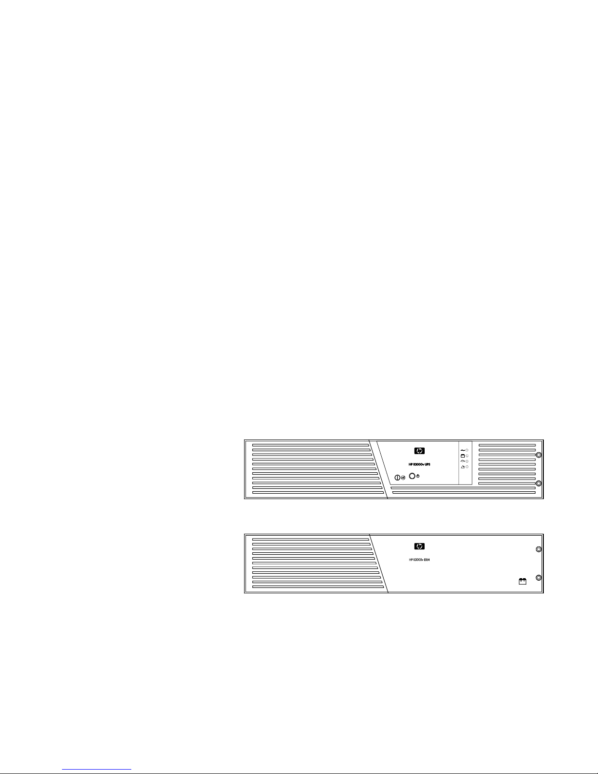
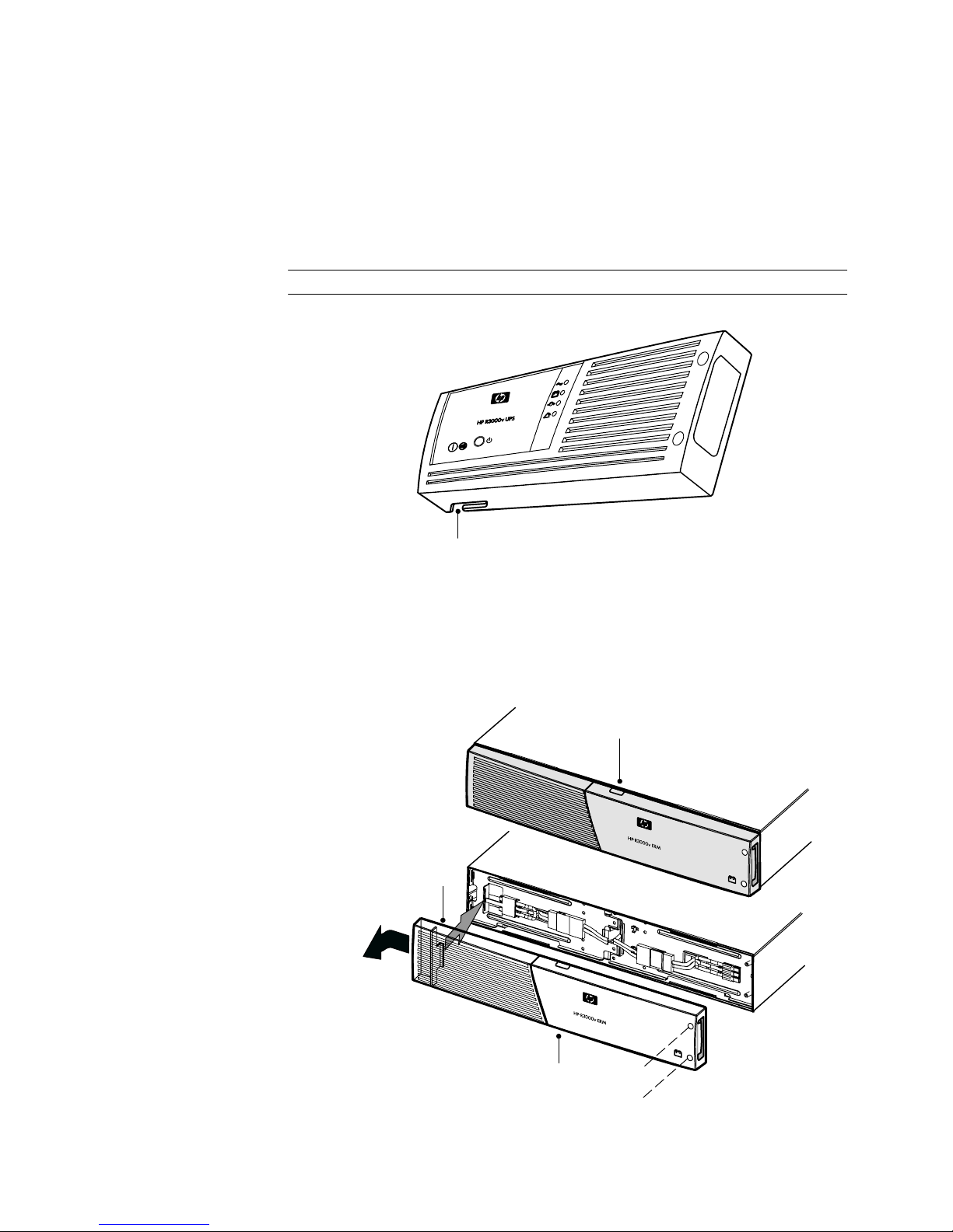
Figure 1 shows the HP R3000v UPS, and Figure 2 shows the optional ERM.
Figure 1 The HP R3000v UPS
Figure 2 The HP R3000v ERM
HP R3000v UPS User Guide S 164201731 Rev 1
1
Page 8

INTRODUCTION
2
HP R3000v UPS User Guide S 164201731 Rev 1
Page 9

Chapter 2 Safety Warnings
IMPORTANT SAFETY INSTRUCTIONS
SAVE THESE INSTRUCTIONS
This manual contains important instructions that you should follow during installation and
maintenance of the UPS and batteries. Please read all instructions before operating the
equipment and save this manual for future reference.
This UPS contains LETHAL VOLTAGES. All repairs and service should be performed by
AUTHORIZED SERVICE PERSONNEL ONLY. There are NO USER SERVICEABLE PARTS
inside the UPS.
S This UPS contains its own energy source (batteries). The UPS output may carry live voltage
even when the UPS is not connected to an AC supply.
S To reduce the risk of fire or electric shock, install this UPS in a temperature and humidity
controlled, indoor environment, free of conductive contaminants. Ambient temperature must
not exceed 40°C (104°F). Do not operate near water or excessive humidity
(90% maximum).
S To reduce the risk of fire, connect only to a circuit provided with branch circuit overcurrent
protection in accordance with the National Electrical Code
S Output overcurrent protection and disconnect switch must be provided by others.
S To comply with international standards and wiring regulations, the sum of the leakage
current of the UPS and the total equipment connected to the output of this UPS must not have
an earth leakage current greater than 3.5 milliamperes.
S If installing an optional rackmount Extended Runtime Module, install the ERM or ERMs
directly below the UPS so that all wiring between the cabinets is installed behind the front
bezels and is inaccessible to users. The maximum number of ERMs per UPS is four.
DANGER
WARNING
®
(NEC®), ANSI/NFPA 70.
CAUTION
S Batteries can present a risk of electrical shock or burn from high short-circuit current. Observe
proper precautions. Servicing should be performed by qualified service personnel
knowledgeable of batteries and required precautions. Keep unauthorized personnel away
from batteries.
S Proper disposal of batteries is required. Refer to your local codes for disposal requirements.
S Never dispose of batteries in a fire. Batteries may explode when exposed to flame.
S Replace batteries with the same number and type of batteries as originally installed in the
UPS.
S If the UPS requires any type of transportation, disconnect the UPS internal batteries before
transporting (see page 26).
HP R3000v UPS User Guide S 164201731 Rev 1
3
Page 10

SAFETY WARNINGS
4
HP R3000v UPS User Guide S 164201731 Rev 1
Page 11

Chapter 3 Installation
This section explains:
S Equipment inspection
S Unpacking the cabinet
S Checking the accessory kit
S Cabinet installation
S Wiring installation
S Initial startup
S UPS rear panel
Inspecting the Equipment
If any equipment has been damaged during shipment, keep the shipping cartons and
packing materials for the carrier or place of purchase and file a claim for shipping damage.
If you discover damage after acceptance, file a claim for concealed damage.
To file a claim for shipping damage or concealed damage: 1) File with the carrier within
15 days of receipt of the equipment; 2) Send a copy of the damage claim within 15 days
to your service representative.
Unpacking the Cabinet
NOTE: Check the battery recharge date on the shipping carton label. If the date has expired
and the batteries were never recharged, do notusetheUPS.Contactyourservice
representative.
CAUTION
S Unpacking the cabinet in a low-temperature environment may cause condensation to occur
in and on the cabinet. Do not install the cabinet until the inside and outside of the cabinet
are absolutely dry (hazard of electric shock).
S The cabinet is heavy (see page 35). Use caution to unpack and move the cabinet.
Use care when moving and opening the carton. Leave the components packaged until you
are ready to install.
To unpack the cabinet and accessories:
1. Open the outer carton and remove the accessories packaged with the cabinet.
2. Carefully lift the cabinet out of the outer carton.
3. Discard or recycle the packaging in a responsible manner, or store it for future use.
Place the cabinet in a protected area that has adequate airflow and is free of humidity,
flammable gas, and corrosion.
HP R3000v UPS User Guide S 164201731 Rev 1
5
Page 12

INSTALLATION
Checking the Accessory Kit
Verify that the following additional items are included with the UPS:
S UPS user guide
S CD with HP Value UPS Manager
S USB cable
S Serial cable
S Two power cords (one for India and one for China)
If you ordered an optional Extended Runtime Module, verify that an ERM user guide is
included with the ERM.
NOTE: Discard the ERM user guide if you are installing the ERM with a new UPS at the same
time. Use the UPS user guide to install both the UPS and the ERM.
Rackmount Installation
The HP R3000v UPS rackmount cabinet comes with all of the hardware required for
installation in a standard EIA or JIS seismic rackmount configuration with square and round
mounting holes. The rail assemblies adjust to mount in 48-cm (19-inch) racks with front to
rear rail distances from 61 to 76 cm (24 to 30 inches) deep.
Checking the Rail Kit Accessories
Verify that the following rail kit items are included for each cabinet:
S Left rail assembly:
-Leftrail
-Rearrail
-(3)M4
×8 pan-head screws
S Right rail assembly:
- Right rail
-Rearrail
-(3)M4
×8 pan-head screws
S Rail hardware kit:
- (10) M6
- (10) M6 hex cage nuts
- (10) M6 square cage nuts
- (2) rear stop brackets
-(6)M3
×16 pan-head screws
×8 pan-head screws
S Mounting bracket kit:
- (2) mounting brackets
-(8)M4
×6flat-headscrews
6
HP R3000v UPS User Guide S 164201731 Rev 1
Page 13
INSTALLATION
Tools Required
To assemble the components, the following tools may be needed:
S Medium flat-bladed screwdriver
S Phillips
®
#2 screwdriver
S 7 and 8 mm wrench or socket
Rackmount Setup
CAUTION
S The cabinet is heavy (see page 35). A minimum of two people are required to remove the
cabinet from its carton.
S If installing optional ERM(s), install the ERM(s) directly below the UPS so that all wiring
between the cabinets is installed behind the front bezels and is inaccessible to users.
NOTE: Mounting rails are required for each individual cabinet.
To install the rail kit:
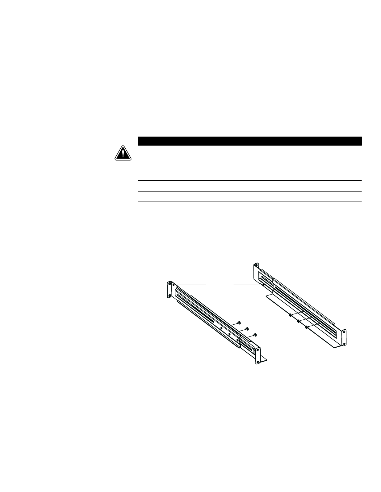
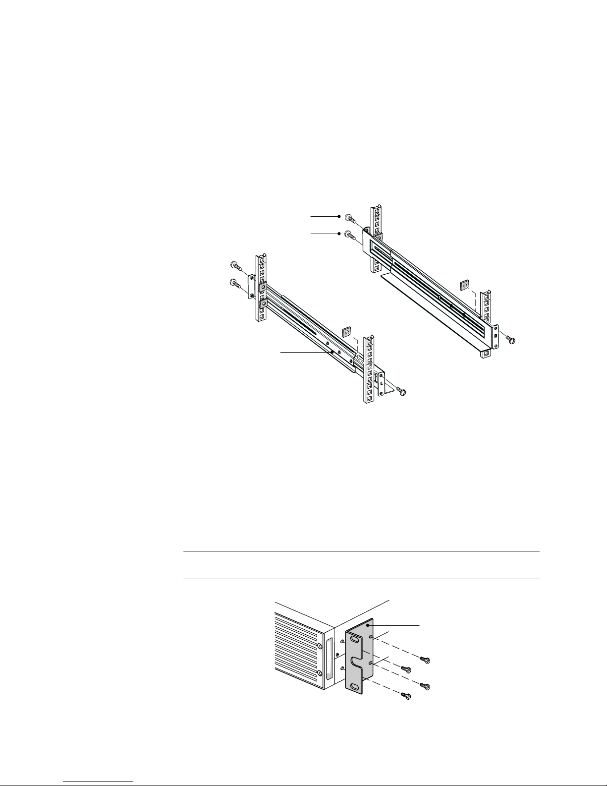
1. Attach the left and right rails to the rear rails as shown in Figure 3. Do not tighten the
screws.
Adjusteachrailsizeforthedepthofyourrack.
Rear Rails
M4
×8Pan-Head
Screws (6 places)
Left Rail
Figure 3 Attaching the Rails
Right Rail
HP R3000v UPS User Guide S 164201731 Rev 1
7
Page 14
INSTALLATION
2. SelecttheproperholesintherackforpositioningtheUPSintherack(seeFigure4).
The rails occupy four positions on the front and rear of the rack.
3. Secure one rail assembly to the front of the rack with one M6
and one M6 cage nut.
4. Using two M6 cage nuts and two M6
×16 pan-head screws, attach the rail assembly
to the rear of the rack.
Position 4
Position 1
M6 Cage Nuts
(6 places)
Tighten
adjustment
screws after rail
attachment
(3 places each rail).
M6×16 Pan-Head
Screws (6 places)
Figure 4 Securing the Rails
×16 pan-head screw
Front of Rack
5. Repeat Steps 3 and 4 for the other rail assembly.
6. Tighten the three adjustment screws on each rail assembly.
7. If installing optional cabinets, repeat Step 1 through Step 6 for each rail kit.
8. Place the UPS on a flat, stable surface with the front of the cabinet facing you.
9. Align the mounting brackets with the screw holes on each side of the UPS and secure
with the supplied M4
×6 flat-head screws (see Figure 5).
NOTE: There are two sets of four mounting holes on each side of the UPS: a forward position
and a middle position. Choose the position that meets your configuration needs.
Mounting
Bracket
M4×6Flat-Head
Screws (4 places)
Figure 5 Installing the Mounting Brackets (Forward Position Shown)
10. If installing optional cabinets, repeat Steps 8 and 9 for each cabinet.
8
HP R3000v UPS User Guide S 164201731 Rev 1
Page 15
INSTALLATION
CAUTION
The ERM is heavy (see page 35). A minimum of two people are required to lift the cabinet into
the rack.
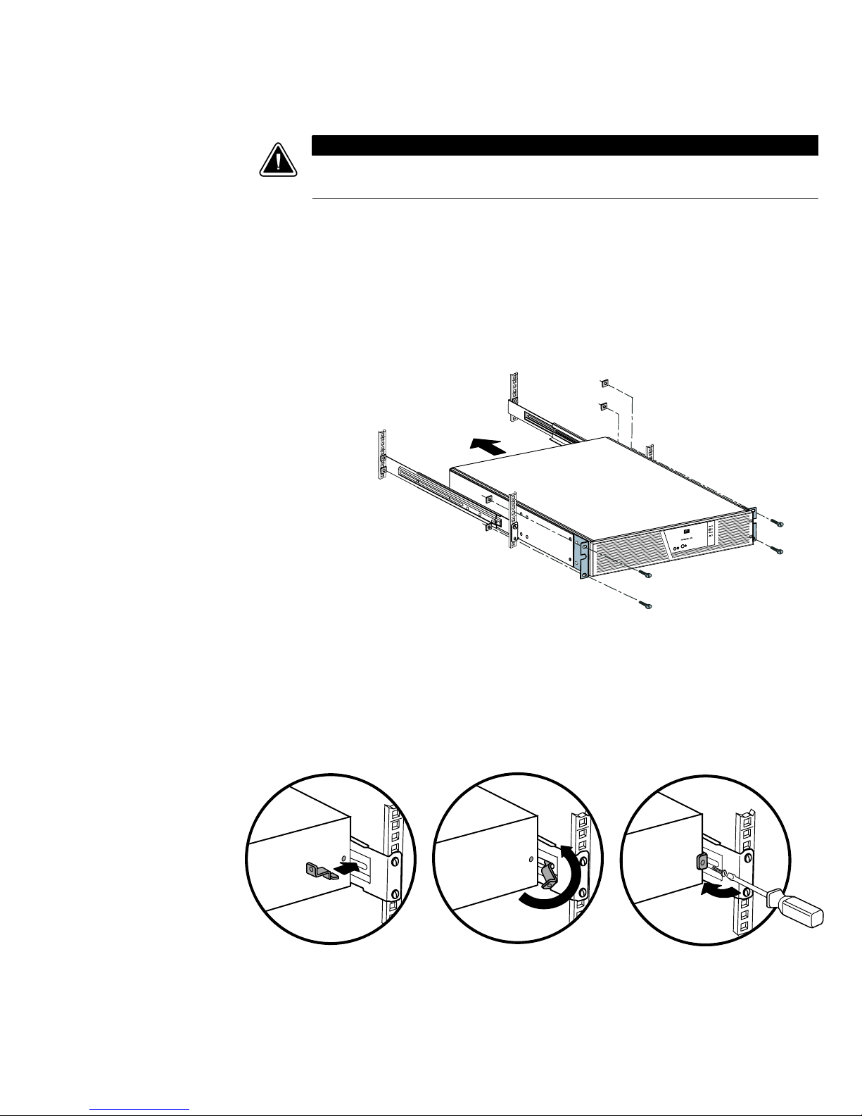
11. Slide the UPS and any optional cabinets into the rack.
12. Secure the front of the UPS to the rack using two M6
×16 pan-head screws and two
M6 cage nuts on each side (see Figure 6). Install the bottom screw on each side
through the bottom hole of the mounting bracket and the bottom hole of the rail
assembly.
Repeat for any optional cabinets.
M6 Cage Nuts
(4 places)
M6×16 Pan-Head
Screws (4 places)
Figure 6 Securing the Front of the Cabinet
13. Optional. Insert a rear stop bracket through the inside of each rail assembly behind the
UPS. Rotate each bracket and slide the bracket until it fits tightly against the UPS’s rear
panel. Secure each bracket to the UPS with one M3
×8 pan-head screw. See
Figure 7.
Rear Stop Bracket
Repeat for any optional cabinets.
Figure 7 Securing the Back of the Cabinet (Optional)
14. Continue to “Rackmount Wiring Installation” on page 10.
HP R3000v UPS User Guide S 164201731 Rev 1
M3
×8 Pan-Head Screw
9
Page 16
INSTALLATION
Rackmount Wiring Installation
This section explains:
S Installing the UPS, including connecting the UPS internal batteries
S Connecting any optional ERMs
Installing the UPS
NOTE: Do not make unauthorized changes to the UPS; otherwise, damage may occur to your
equipment and void your warranty.
NOTE: Do not plug the UPS power cord into a power outlet until after the installation is
completed.
To install the UPS:
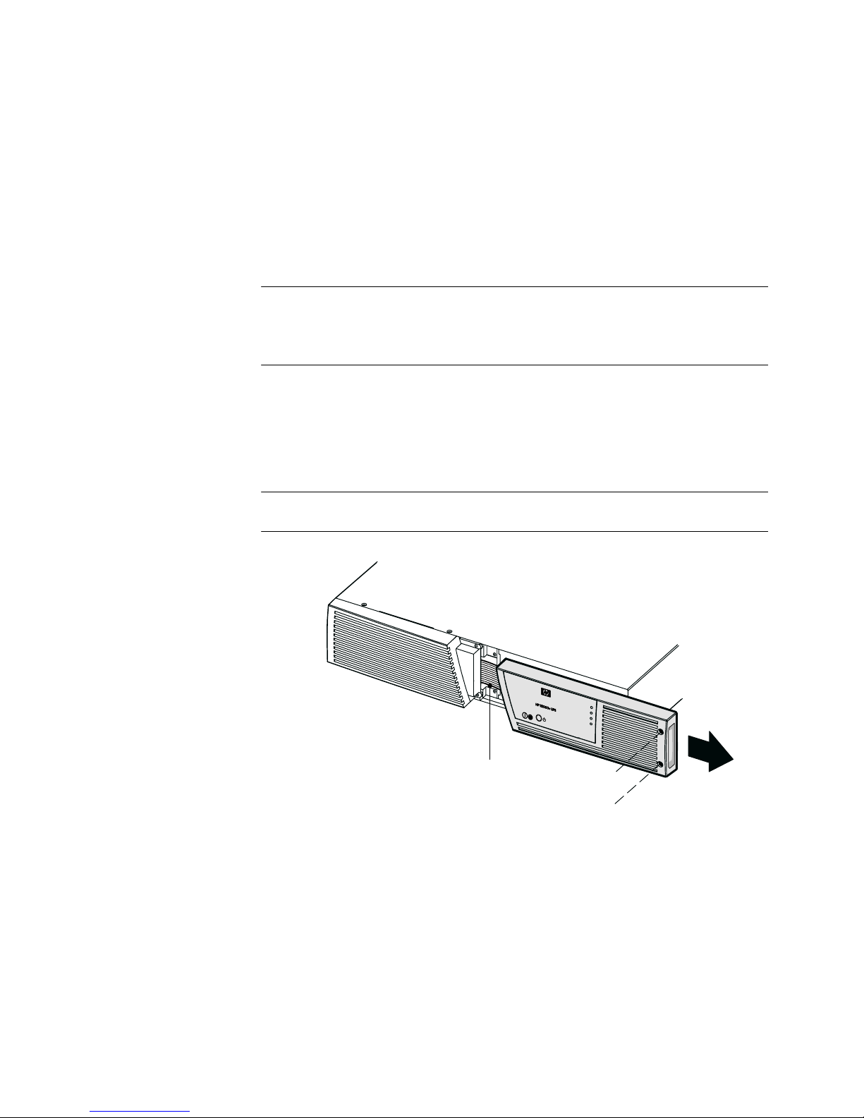
1. RemovetheUPSrightfrontbezel.SeeFigure8.
To remove the bezel, loosen the two captive screws on the right side of the bezel.
Grasp the top and bottom of the bezel and slide the bezel to the right.
NOTE: A ribbon cable connects the control panel to the UPS. Do not pull on the cable or
disconnect it.
NOTE: Leave
ribbon cable
connected.
Figure 8 Removing the UPS Right Front Bezel
10
HP R3000v UPS User Guide S 164201731 Rev 1
Page 17
INSTALLATION
NOTE: A small amount of arcing may occur when connecting the internal batteries. This is
normal and will not harm personnel. Connect the cables quickly and firmly.
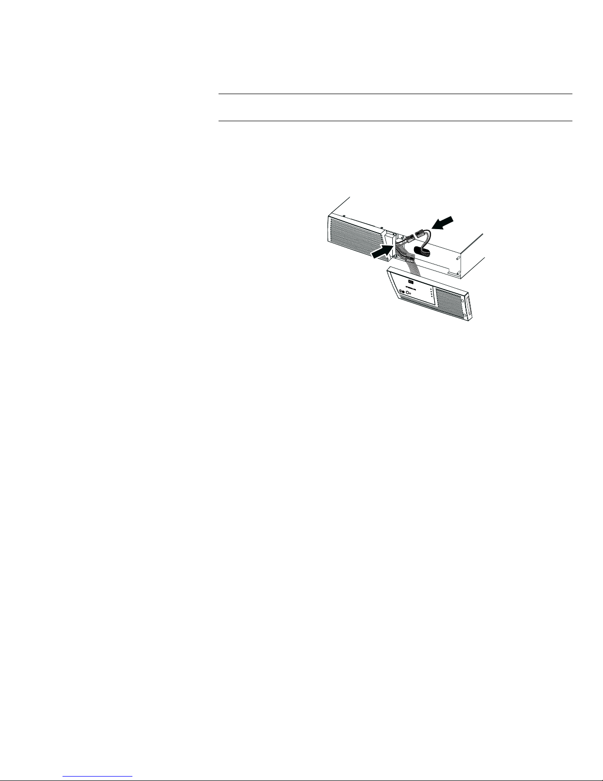
2. Connect the internal battery connector (see Figure 9).
Connect red to red, and black to black. Press the two parts tightly together to ensure a
proper connection.
Figure 9 Connecting the UPS Internal Batteries
3. If you are installing ERMs, see the section, “Connecting the ERM(s),” before continuing
with the UPS installation.
4. Replace the UPS right front bezel.
To replace the bezel, verify that the ribbon cable is protected and (if ERMs are
installed) the ERM cable is routed through the knockout on the bottom of the bezel.
Slide the bezel to the left until it aligns with the left front bezel. Tighten the two captive
screws on the right side of the right front bezel.
5. If you are installing power management software, connect your computer to one of the
communication ports using the appropriate cable (supplied). See page 21 for more
information.
6. If your rack has conductors for grounding or bonding of ungrounded metal parts,
connect the ground cable (not supplied) to the ground bonding screw. See Figure 13
on page 15 for the location of the ground bonding screw.
7. Continue to “UPS Initial Startup” on page 14.
HP R3000v UPS User Guide S 164201731 Rev 1
11
Page 18
INSTALLATION
Connecting the ERM(s)
To install the optional ERM(s) for a UPS:
1. On the bottom of the UPS right front bezel, remove the knockout for the ERM cable.
SeeFigure10.
NOTE: Use care to protect the control panel and the connected ribbon cable from damage.
ERM Cable Knockout
Figure 10 Removing the Knockout
2. Remove the front bezel of each ERM. See Figure 11.
To remove the bezel, loosen the two captive screws on the right side of the bezel.
Grasp the sides of the bezel. Slide the bezel to the left and then away from the
cabinet.
Top ERM Cable Knockout
ERM Bezel Hook
12
HP R3000v UPS User Guide S 164201731 Rev 1
Bottom ERM Cable Knockout
(underneath bezel)
Figure 11 Removing the ERM Front Bezel
Page 19
INSTALLATION
3. For the bottom (or only) ERM, remove the ERM cable knockout on the top of the ERM
front bezel. See Figure 11 for the location of the top ERM cable knockout.
4. If you are installing more than one ERM, for each additional ERM remove the ERM
cable knockout on the top and bottom of the ERM front bezel. See Figure 11 for the
location of the ERM cable knockouts.
NOTE: A small amount of arcing may occur when connecting an ERM to the UPS. This is
normal and will not harm personnel. Insert the ERM cable into the UPS battery connector quickly
and firmly.
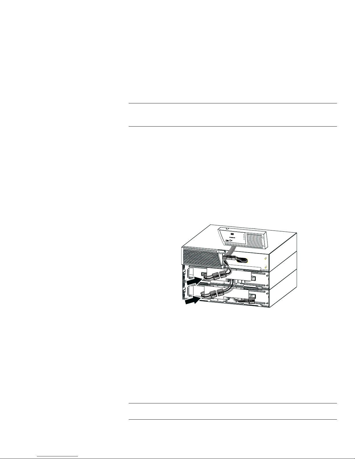
5. Plug the ERM cable(s) into the battery connector(s) as shown in Figure 12. Up to four
ERMs may be connected to the UPS.
Connect red to red, black to black, and green to green. Press the two parts tightly
together to ensure a proper connection.
To connect a second ERM, unclip the ERM connector on the first ERM and pull gently to
extend the wiring to the ERM connector on the second ERM. Repeat for any additional
ERMs.
6. Verify that the ERM connections are tight and that adequate bend radius and strain
relief exist for each cable.
Figure 12 Typical ERM Installation
7. Replace the ERM front bezel.
To replace the bezel, verify that the ERM cables are routed through the ERM cable
knockouts. Slide the bezel from the left to the right until it connects with the bezel hook
near the left side of the ERM cabinet. Tighten the two captive screws on the right side
of the front bezel. For reference, see Figure 11 on page 12.
Repeat for each additional ERM.
8. Verify that all wiring connecting the UPS and ERM(s) is installed behind the front bezels
and is inaccessible to users.
NOTE: To ensure maximum battery runtime, configure the UPS for the correct number of ERMs
through the HP Value UPS Manager software. Refer to the HP Value UPS Manager manual.
9. Return to Step 4 on page 11 to continue the UPS installation.
HP R3000v UPS User Guide S 164201731 Rev 1
13
Page 20

INSTALLATION
UPS Initial Startup
To start up the UPS:
NOTE: Verify that the total equipment ratings do not exceed the UPS capacity to prevent an
overload alarm.
1. Verify that the internal batteries are connected. See “Installing the UPS” on page 10.
2. If optional ERMs are installed, verify that the ERMs are connected to the UPS. See
“Connecting the ERM(s)” on page 12.
3. Plug the equipment to be protected into the UPS, but do not turn on the protected
equipment.
4. Make any necessary provisions for cord retention and strain relief.
5. Plug the detachable UPS power cord into the input connector on the UPS rear panel.
6. Plug the UPS power cord into a power outlet.
7. Press the
(Output On) button on the UPS front panel for at least one second.
8. Check the UPS front panel for active alarms. Resolve any active alarms before
continuing. See “Troubleshooting” on page 39.
If the
(Alarm) indicator is on, do not proceed until all alarms are clear. Check the
UPS status from the front panel to view the active alarms. Correct the alarms and
restart, if necessary.
9. Verify that the
(Power On) indicator is illuminated, indicating that the UPS is
operating normally and any loads are powered.
The UPS should be in Normal mode.
10. If optional ERMs are installed, see “Configuring the UPS for ERMs” on page 20 to set
thenumberofinstalledERMs.
NOTE: The batteries charge to 90% capacity in less than 3 hours. However, to fully charge, HP
recommends that the batteries charge for 48 hours after installation or long-term storage.
NOTE: Verify that the UPS firmware is updated. See “Updating the UPS Firmware” on
page 33.
14
HP R3000v UPS User Guide S 164201731 Rev 1
Page 21
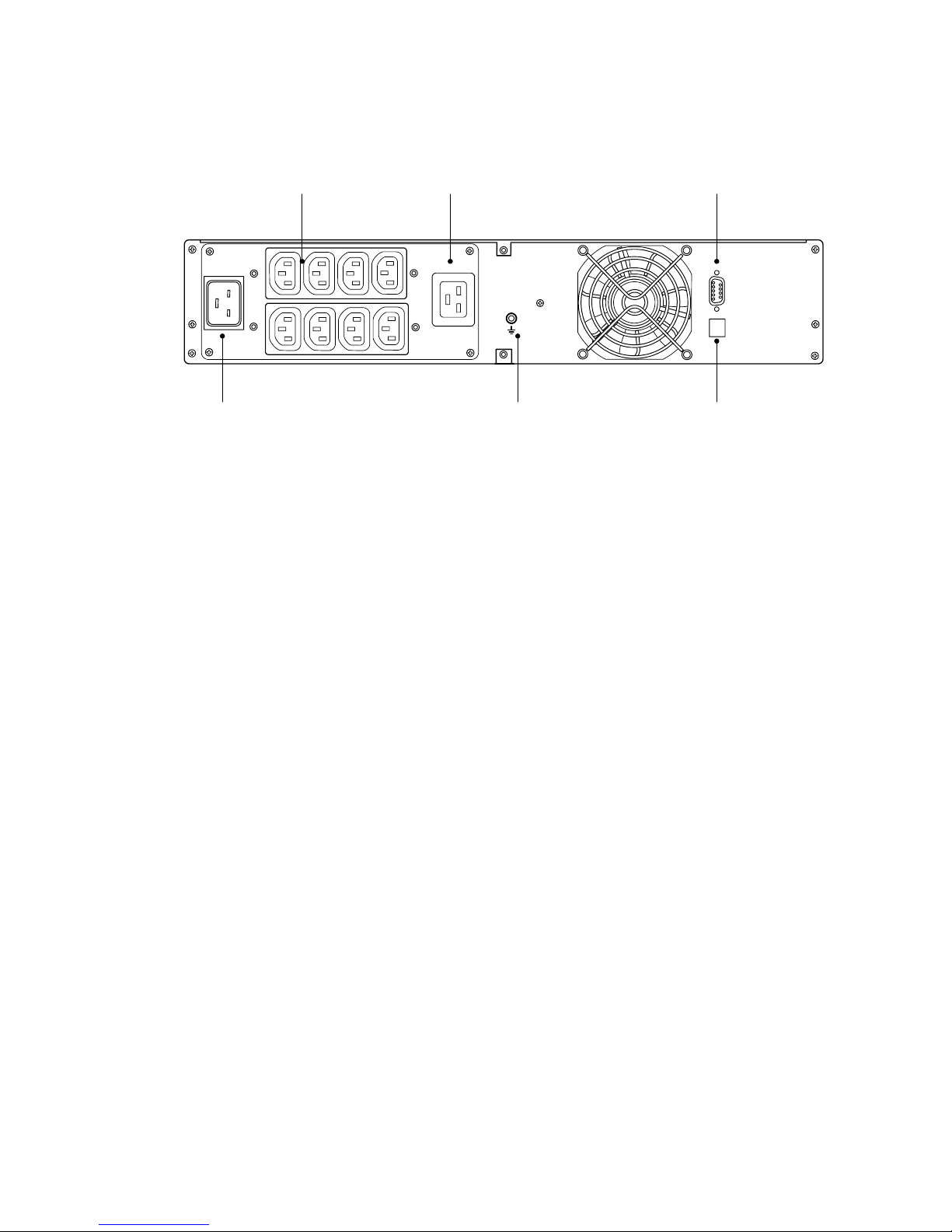
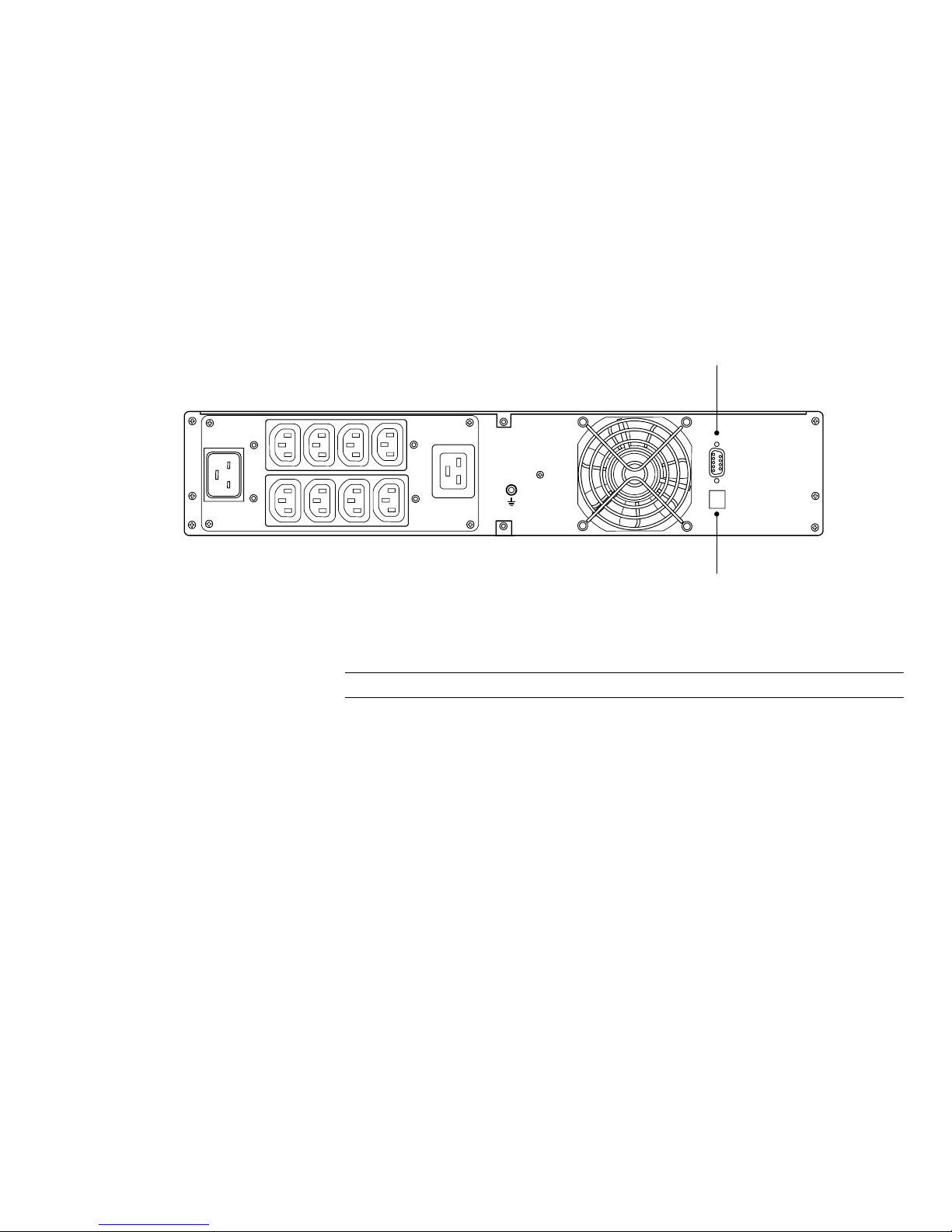
Rear Panel
INSTALLATION
(8) IEC 320-10A
Output Receptacles
IEC C20-16A Input Connector
(1) IEC 320-16A
Output Receptacle
Ground Bonding Screw
Figure 13 HP R3000v UPS
RS-232 Communication
Port
USB Port
HP R3000v UPS User Guide S 164201731 Rev 1
15
Page 22

INSTALLATION
16
HP R3000v UPS User Guide S 164201731 Rev 1
Page 23
Chapter 4 Operation
This chapter contains information on how to use the HP R3000v UPS, including front panel
operation, operating modes, UPS startup and shutdown, and battery settings.
Control Panel Functions
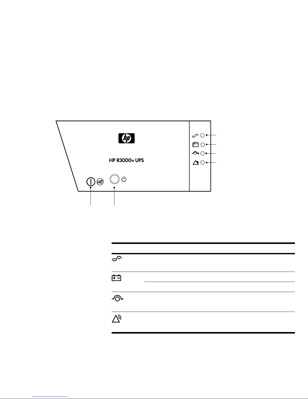
The UPS has two buttons and four LEDs on the right front bezel (see Figure 14).
Power On Indicator (green)
On Battery Indicator (yellow)
Bypass Indicator (yellow)
Alarm Indicator (red)
Output On/Alarm
Silence Button
Output Off Button
Figure 14 HP R3000v UPS Control Panel
Table 1 shows the indicator status and description.
Table 1. Indicator Descriptions
Indicator Status Description
On The UPS is operating normally.
Green
On The UPS is in Battery mode.
Yellow
Yellow
Red
Flashing The battery voltage is below the warning level.
On The UPS is in Bypass mode.
On The UPS has an active alarm or fault. See “Troubleshooting” on
page 39 for additional information.
HP R3000v UPS User Guide S 164201731 Rev 1
17
Page 24

OPERATION
Operating Modes
The HP R3000v UPS front panel indicates the UPS status through the UPS indicators (see
Figure 14 on page 17).
Normal Mode
During Normal mode, the (Power On) indicator illuminates and the UPS is powered
from the utility. The UPS monitors and charges the batteries as needed and provides filtered
powerprotectiontoyourequipment.
Battery Mode
When the UPS is operating during a power outage, the alarm beeps once every five
seconds and the
When the utility power returns, the UPS transfers to Normal mode operation while the
battery recharges.
(On Battery) indicator illuminates.
If battery capacity becomes low while in Battery mode, the
(On Battery) indicator
flashes slowly and the audible alarm beeps once every second. If the Battery Low alarm is
set, the
(Alarm) indicator also illuminates. This warning is approximate, and the actual
time to shutdown may vary significantly.
NOTE: Depending on the UPS load and the number of Extended Runtime Modules (ERMs)
connected, the Battery Low warning may occur before the batteries reach 25% capacity. See
Table 9 on page 37 for estimated runtimes.
When utility power is restored after the UPS shuts down, the UPS automatically restarts.
NOTE: You can configure the auto-restart option through the HP Value UPS Manager software
(see page 23).
Bypass Mode
NOTE: You can manually transfer the UPS to Bypass mode by pressing the (Output Off)
button once within four seconds. If Bypass mode is not available, the UPS returns to its original
operating mode.
NOTE: You can configure Bypass mode options through the HP Value UPS Manager software
(see page 23).
In the event of a UPS overload or internal failure, the UPS transfers your equipment to utility
power. Battery mode is not available and your equipment is not protected; however, the
utility power continues to be passively filtered by the UPS. The
illuminates.
(Bypass) indicator
The UPS remains in Bypass mode for at least five seconds (if the bypass source remains
acceptable). If three transfers to bypass occur within 10 minutes for any reason other than
user command, the UPS locks in Bypass mode for one hour or until any control button is
pressed.
18
HP R3000v UPS User Guide S 164201731 Rev 1
Page 25

OPERATION
The UPS transfers to Bypass mode when:
S The UPS detects an internal failure.
S The UPS has an overtemperature condition.
S The UPS has an overload condition listed in Table 7 on page 36.
NOTE: The UPS shuts down after a specified delay for overload conditions listed in Table 7 on
page 36. The UPS logic power remains on to alarm the fault.
Standby Mode
When the UPS is turned off and remains plugged into a power outlet, the UPS is in Standby
mode. The
equipment. The battery recharges when necessary.
If utility fails and output turns off due to drained batteries or UPS internal failure, the UPS is in
Standby mode.
(Power On) indicator is off, indicating that power is not available to your
UPS Startup and Shutdown
If the UPS is waiting on commands and utility fails, unit and logic power turn off in
approximately 30 seconds.
To start up or shut down the UPS, see:
S “Starting the UPS” below
S “Starting the UPS on Battery” on page 20
S “UPS Shutdown” on page 20
Starting the UPS
To start the UPS:
1. Verify that the UPS power cord is plugged in.
2. Press the
3. Check the UPS front panel for active alarms. Resolve any active alarms before
continuing. See “Troubleshooting” on page 39.
If the
UPS status from the front panel to view the active alarms. Correct the alarms and
restart, if necessary.
(Output On) button on the UPS front panel for at least one second.
(Alarm) indicator is on, do not proceed until all alarms are clear. Check the
4. Verify that the
operating normally and any loads are powered.
The UPS should be in Normal mode.
(Power On) indicator is illuminated, indicating that the UPS is
HP R3000v UPS User Guide S 164201731 Rev 1
19
Page 26

OPERATION
Starting the UPS on Battery
NOTE: Before using this feature, the UPS must have been powered by utility power with output
enabled at least once.
To start the UPS on battery:
Configuring the UPS for ERMs
1. Press the
The UPS cycles through Standby mode to Battery mode. The
illuminates. The UPS supplies power to your equipment.
2. Check the UPS front panel for active alarms. Resolve any active alarms before
continuing. See “Troubleshooting” on page 39.
(Output On) button on the UPS front panel for at least one second.
(On Battery) indicator
UPS Shutdown
To shut down the UPS,
1. Press the
The UPS then transfers to Standby mode (if utility power is available) and the
(Power On) indicator turns off.
NOTE: Pressing the (Output Off) button once within four seconds transfers the UPS to Bypass
mode, if available. If Bypass mode is not available, the UPS returns to its original operating
mode.
2. Unplug the UPS from the power outlet.
To ensure maximum battery runtime, configure the UPS for the correct number of ERMs
through the HP Value UPS Manager software.
(Output Off) button on the UPS front panel twice within four seconds.
Battery Tests
Automatic battery tests run approximately every 30 days. You can also manually perform a
battery test by pressing the
During the battery test, the UPS transfers to Battery mode and discharges the batteries for
25 seconds under the existing load.
To run a battery test:
S The UPS must be in Normal mode, with no active alarms.
S The batteries must be fully charged.
S The bypass voltage must be acceptable.
S No manual battery test was initiated previously in the same charging cycle.
To pass the battery test, the battery voltage must remain above the threshold value during
discharge.
20
HP R3000v UPS User Guide S 164201731 Rev 1
(Output On) button for half a second.
Page 27
Chapter 5 Communication
This section describes the:
S Communication ports (RS-232 and USB)
S HP Value UPS Manager software
Figure 15 shows the location of the communication options on a typical UPS.
Figure 15 Communication Options
RS-232
USB
RS-232 and USB Communication Ports
NOTE: The communication speed of the USB port is fixed at 2400 bps.
To establish communication between the UPS and a computer, connect your computer to
one of the UPS communication ports using an appropriate communication cable (supplied).
See Figure 15 for the communication port locations.
When the communication cable is installed, power management software can exchange
data with the UPS. The software polls the UPS for detailed information on the status of the
power environment. If a power emergency occurs, the software initiates the saving of all
data and an orderly shutdown of the equipment.
HP R3000v UPS User Guide S 164201731 Rev 1
21
Page 28

COMMUNICATION
ThecablepinsfortheRS-232communicationport are identified in Figure 16 and the pin
functions are described in Table 2.
5
9
4
8
3
7
2
6
1
Figure 16 RS-232 Communication Port (DB-9 Connector)
Table 2 RS-232 Communication Port Pin Assignment
Pin Number Signal Name Function Direction from the UPS
1 DCD Not used —
2 RxD Transmit to external device Out
3 TxD Receive from external device In
4 DTR Not used —
5 GND Signal common (tied to chassis) —
6 DSR Not used —
7 RTS Not used —
8 CTS Not used —
9 RI Not used —
22
HP R3000v UPS User Guide S 164201731 Rev 1
Page 29
HP Value UPS Manager Software
Each HP R3000v UPS ships with HP Value UPS Manager software. To install the HP Value
UPS Manager software, see the instructions accompanying the CD.
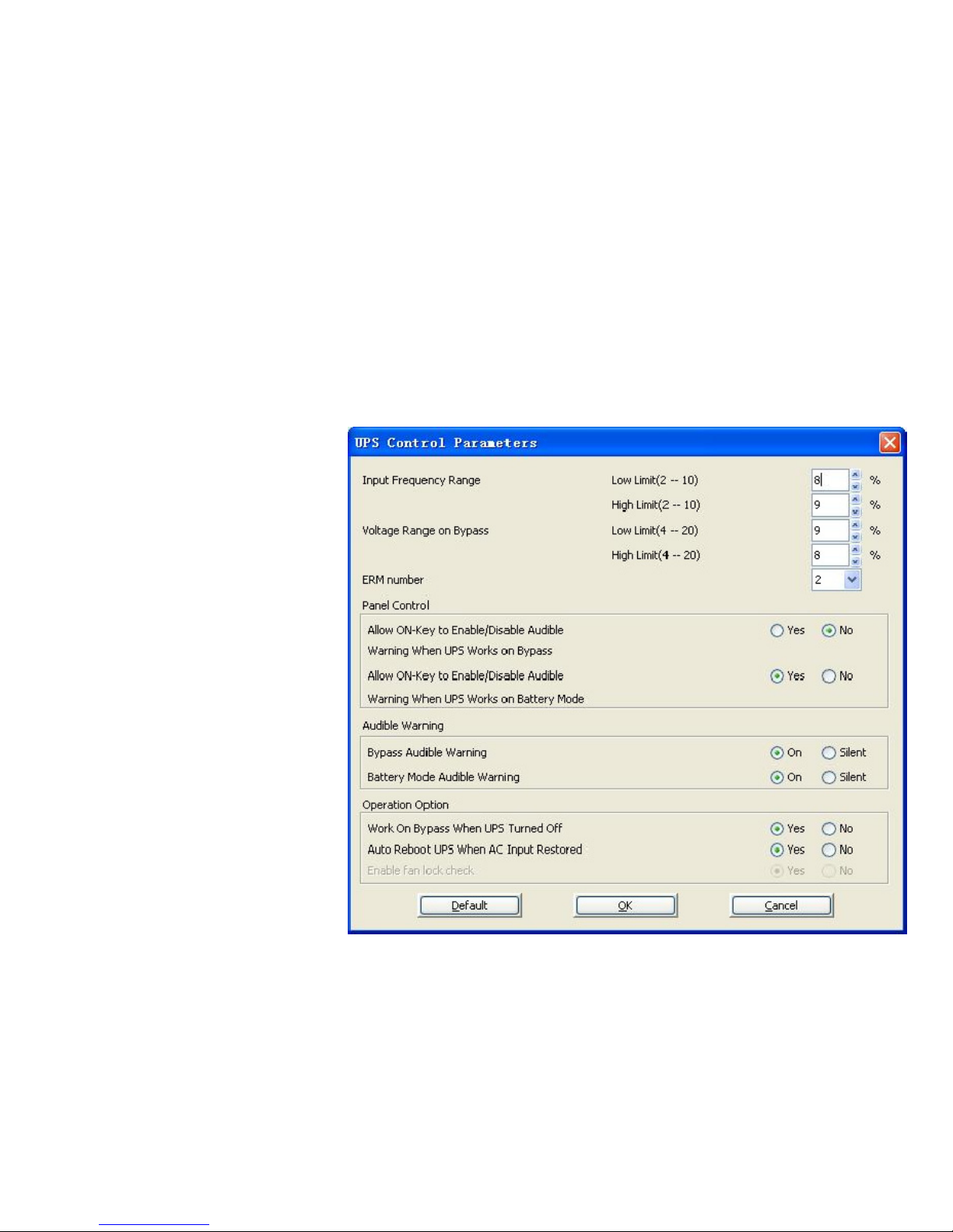
After installing the HP Value UPS Manager software, you can configure UPS parameters:
1. Select UPS Control Parameters from the Device menu.
2. Modify the parameters (see Table 3).
3. Click OK to save any modified parameters. Click Cancel to ignore any changes.
COMMUNICATION
The UPS Control Parameters dialog appears (see Figure 17).
Click Default to revert all settings to the default values.
Figure 17 UPS Control Parameters Dialog
HP R3000v UPS User Guide S 164201731 Rev 1
23
Page 30

COMMUNICATION
Table 3 UPS Control Parameters
Parameter
Unit Maximum Minimum Default Action
Input Frequency Range % 10 2 Low limit: 10
High limit: 10
Voltage Range on Bypass % 20 4 Low limit: 15
High limit: 10
ERM number — 4 0 —
Allow ON-Key to Enable/Disable Audible
— — — Yes When the UPS is in Bypass mode, users can
Warning When UPS Works on Bypass
Allow ON-Key to Enable/Disable Audible
— — — Yes When the UPS is in Battery mode, users can
Warning When UPS Works on Battery
Mode
If the utility power frequency is out of range
(2–10%) while the UPS is in Bypass mode, the
UPS transfers to Battery mode. Enter a low limit
and a high limit for the input frequency range.
If the utility power voltage is out of range
(4–20%) while the UPS is in Bypass mode, the
UPS transfers to Battery mode.
Set the number of Extended Runtime Modules
according to the number of ERMs installed with
the UPS (0–4 ERMs).
turn off the audible a larm (the UPS beeps once
every five seconds) by pressing the (Output
On) button once. To recover the audible alarm,
press the (Output On) button once.
Select “No” to disable the front panel control;
thealarmcannotbeturnedoffwhiletheUPSis
in Bypass mode.
turn off the audible a larm (the UPS beeps once
every five seconds) by pressing the (Output
On) button once. To recover the audible alarm,
press the (Output On) button once.
Select “No” to disable the front panel control;
thealarmcannotbeturnedoffwhiletheUPSis
in Battery mode.
Bypass Audible Warning — — — On When the UPS is in Bypass mode, the audible
alarm will sound.
Select “Silent” to disable the audible alarm
when the UPS is in Bypass mode. When
“Silent” is selected, the (Output On) button
cannot turn on the audible alarm.
Battery Mode Audible Warning — — — On When the UPS is in Battery mode, the audible
alarm will sound.
Select “Silent” to disable the audible alarm
when the UPS is in Battery mode. When
“Silent” is selected, the (Output On) button
cannot turn on the audible alarm.
Work On Bypass When UPS Turned Off — — — No When the UPS is off, Bypass mode is not
available.
Select “Yes” to allow the UPS to provide
bypass power when the UPS is turned off.
Auto Reboot UPS When AC Input Restored — — — Yes If the battery runtime is depleted, the UPS shuts
down. The UPS automatically restarts when
utility power is restored.
Select “No” to stop the UPS from restarting
automatically. The UPS can be manually started
from the front panel only.
24
HP R3000v UPS User Guide S 164201731 Rev 1
Page 31

Chapter 6 UPS Maintenance
This section explains how to:
S Care for the UPS and batteries
S Transport the UPS
S Store the UPS and batteries
S Replace the UPS internal batteries and Extended Runtime Modules
S Test new batteries
S Recycle used batteries or UPS
S Update the UPS firmware
UPS and Battery Care
For the best preventive maintenance, keep the area around the UPS clean and dust-free. If
the atmosphere is very dusty, clean the outside of the system with a vacuum cleaner.
For full battery life, keep the UPS at an ambient temperature of 25°C (77°F).
NOTE: The batteries in the UPS are rated for a 3–5 year service life. The length of service life
varies, depending on the frequency of usage and ambient temperature. Batteries used beyond
expected service life will often have severely reduced runtimes. Replace batteries at least every
5 years to keep units running at peak efficiency.
HP R3000v UPS User Guide S 164201731 Rev 1
25
Page 32

UPS MAINTENANCE
Transporting the UPS
NOTE: The UPS internal batteries MUST be disconnected during transport.
If the UPS requires any type of transportation:
1. Verify that the UPS is unplugged and turned off.
2. RemovetheUPSrightfrontbezel.SeeFigure18.
To remove the bezel, loosen the two captive screws on the right side of the bezel.
Grasp the top and bottom of the bezel and slide the bezel to the right.
NOTE: A ribbon cable connects the control panel to the UPS. Do not pull on the cable or
disconnect it.
NOTE: Leave
ribbon cable
connected.
Figure 18 Removing the UPS Right Front Bezel
3. Disconnect the internal battery connector (see Figure 19).
Figure 19 Disconnecting the UPS Internal Batteries
4. Replace the UPS front bezel.
26
HP R3000v UPS User Guide S 164201731 Rev 1
Page 33

Storing the UPS and Batteries
When to Replace Batteries
Replacing Batteries
UPS MAINTENANCE
If you store the UPS for a long period, recharge the battery every 6 months by connecting
the UPS to utility power. The batteries charge to 90% capacity in less than 3 hours.
However, to fully charge, HP recommends that the batteries charge for 48 hours after
long-term storage.
Check the battery recharge date on the shipping carton label. If the date has expired and
the batteries were never recharged, do not use the UPS. Contact your service representative.
When the (Alarm) indicator illuminates and the audible alarm beeps, the batteries may
need replacing. Contact your service representative to order new batteries.
NOTE: DO NOT DISCONNECT the batteries while the UPS is in Battery mode.
Batteries can be replaced easily without turning the UPS off or disconnecting the load.
If you prefer to remove input power to change the batteries, see “UPS Shutdown” on
page 20.
Consider all warnings, cautions, and notes before replacing batteries.
WARNING
S Servicing should be performed by qualified service personnel knowledgeable of batteries
and required precautions. Keep unauthorized personnel away from batteries.
S Batteries can present a risk of electrical shock or burn from high short circuit current.
Observe the following precautions: 1) Remove watches, rings, or other metal objects;
2) Use tools with insulated handles; 3) Do not lay tools or metal parts on top of batteries,
4) Wear rubber gloves and boots.
S When replacing batteries, replace with the same type and number of batteries or battery
packs. Contact your service representative to order new batteries.
S Proper disposal of batteries is required. Refer to your local codes for disposal requirements.
S Never dispose of batteries in a fire. Batteries may explode when exposed to flame.
S Do not open or mutilate the battery or batteries. Released electrolyte is harmful to the skin
and eyes and may be extremely toxic.
S Determine if the battery is inadvertently grounded. If inadvertently grounded, remove source
from ground. Contact with any part of a grounded battery can result in electrical shock. The
likelihood of such shock can be reduced if such grounds are removed during installation and
maintenance (applicable to equipment and remote battery supplies not having a grounded
supply circuit).
S ELECTRIC ENERGY HAZARD. Do not attempt to alter any battery wiring or connectors.
Attempting to alter wiring can cause injury.
S Disconnect charging source prior to connecting or disconnecting battery terminals.
HP R3000v UPS User Guide S 164201731 Rev 1
27
Page 34

UPS MAINTENANCE
Replacing UPS Internal Batteries
CAUTION
The UPS internal batteries are heavy. Use caution when handling the heavy batteries.
The internal batteries are located behind the UPS right front bezel. The internal batteries are
packaged together as one unit for easier handling.
To replace the UPS internal batteries:
1. RemovetheUPSrightfrontbezel(seeFigure20).
To remove the bezel, loosen the two captive screws on the right side of the bezel.
Grasp the top and bottom of the bezel and slide the bezel to the right.
NOTE: A ribbon cable connects the control panel to the UPS. Do not pull on the cable or
disconnect it.
NOTE: Leave
ribbon cable
connected.
Figure 20 Removing the UPS Right Front Bezel
2. Disconnect the internal battery connector (see Figure 21).
Battery Cover Plate
Internal Battery
Connector
Figure 21 Disconnecting the UPS Internal Batteries (Shown without ERMs)
28
HP R3000v UPS User Guide S 164201731 Rev 1
Page 35

UPS MAINTENANCE
3. Grasp an edge of the battery cover plate and pull it forward gently. Remove and retain
the battery cover plate.
4. Carefully pull the handle on the battery tray and slide the battery package slowly out
onto a flat, stable surface; use two hands to support the battery package. See
“Recycling the Used Battery or UPS” on page 33 for proper disposal.
NOTE: Verify that the replacement batteries have the same rating as the batteries being
replaced.
5. Slide the new battery package into the cabinet. Push the battery package in firmly.
6. Replace the battery cover plate onto the screw mounts, threading the battery connector
through the access slot.
NOTE: A small amount of arcing may occur when connecting the internal batteries. This is
normal and will not harm personnel. Connect the cables quickly and firmly.
7. Reconnect the internal battery connector.
Connect red to red, and black to black. Press the two parts tightly together to ensure a
proper connection.
8. Replace the UPS right front bezel.
To replace the bezel, verify that the ribbon cable is protected and (if ERMs are
installed) the ERM cable is routed through the knockout on the bottom of the bezel.
Slide the bezel to the left until it aligns with the left front bezel. Tighten the two captive
screws on the right side of the bezel.
9. Continue to “Testing New Batteries” on page 32.
HP R3000v UPS User Guide S 164201731 Rev 1
29
Page 36

UPS MAINTENANCE
Replacing ERMs
CAUTION
The ERM is heavy (see page 35). A minimum of two people are required to lift the cabinet into
the rack.
To replace the ERMs:
1. RemovetheUPSrightfrontbezel(seeFigure20).
To remove the bezel, loosen the two captive screws on the right side of the bezel.
Grasp the top and bottom of the bezel and slide the bezel to the right.
NOTE: A ribbon cable connects the control panel to the UPS. Do not pull on the cable or
disconnect it.
NOTE: Leave
ribbon cable
connected.
Figure 22 Removing the UPS Right Front Bezel
30
HP R3000v UPS User Guide S 164201731 Rev 1
Page 37

UPS MAINTENANCE
2. Remove the front bezel of each ERM. See Figure 23.
To remove the bezel, loosen the two captive screws on the right side of the bezel.
Grasp the sides of the bezel. Slide the bezel to the left and then away from the
cabinet.
Top ERM Cable Knockout
ERM Bezel Hook
Bottom ERM Cable Knockout
(underneath bezel)
Figure 23 Removing the ERM Front Bezel
3. Unplug the ERM cable from the UPS.
If additional ERMs are installed, unplug the ERM cable from the battery connector on
each ERM.
4. If not already installed, install the supplied mounting brackets on the new ERM(s).
5. Replace the ERM(s). See “Recycling the Used Battery or UPS” on page 33 for proper
disposal.
6. Remove the front bezel of each new ERM. See Figure 23.
To remove the bezel, loosen the two captive screws on the right side of the bezel.
Grasp the sides of the bezel. Slide the bezel to the left and then away from the
cabinet.
7. For the bottom (or only) ERM, remove the ERM cable knockout on the top of the ERM
bezel. See Figure 23 for the location of the top ERM cable knockout.
8. If you are installing more than one new ERM, for each additional ERM remove the ERM
cable knockout on the top and bottom of the ERM front bezel. See Figure 23 for the
location of the ERM cable knockouts.
HP R3000v UPS User Guide S 164201731 Rev 1
31
Page 38

UPS MAINTENANCE
NOTE: A small amount of arcing may occur when connecting an ERM to the UPS. This is
normal and will not harm personnel. Insert the ERM cable into the UPS battery connector quickly
and firmly.
9. Plug the ERM cable(s) into the battery connector(s) as shown in Figure 12 on page 13.
Connect red to red, black to black, and green to green. Press the two parts tightly
together to ensure a proper connection.
To connect a second ERM, unclip the ERM connector on the first ERM and pull gently to
extend the wiring to the ERM connector on the second ERM. Repeat for any additional
ERMs.
10. Verify that the ERM connections are tight and that adequate bend radius and strain
relief exist for each cable.
11. Replace the ERM front bezel.
To replace the bezel, verify that the ERM cables are routed through the ERM cable
knockouts. Slide the bezel from the left to the right until it connects with the bezel hook
near the left side of the ERM cabinet. Tighten the two captive screws on the right side
of the front bezel. For reference, see Figure 23 on page 31.
Testing New Batteries
Repeat for each additional ERM.
12. Verify that all wiring connecting the UPS and ERM(s) is installed behind the front bezels
and is inaccessible to users.
13. Replace the UPS right front bezel.
NOTE: The UPS conducts the battery test on the UPS internal batteries and any connected ERMs.
To test new batteries:
1. Plug the UPS into a power outlet for 48 hours to charge the batteries.
2. Press the
3. Verify that the
(Output On) button on the UPS front panel for at least one second.
(Power On) indicator is illuminated, indicating that the UPS is
operating normally and any loads are powered.
The UPS should be in Normal mode.
4. Press the
(Output On) button for half a second to initiate the battery test.
If the UPS is in Normal mode with no active alarms and the bypass voltage is
acceptable, the UPS starts a battery test.
During the battery test, the UPS transfers to Battery mode and discharges the batteries
for 25 seconds under the existing load. The
32
HP R3000v UPS User Guide S 164201731 Rev 1
(On Battery) indicator illuminates.
Page 39

Recycling the Used Battery or UPS
Contact your local recycling or hazardous waste center for information on proper disposal
of the used battery or UPS.
S Do not dispose of the battery or batteries in a fire. Batteries may explode. Proper disposal of
S Do not open or mutilate the battery or batteries. Released electrolyte is harmful to the skin
Do not discard the UPS or the UPS batteries in the trash. This product contains sealed,
lead-acid batteries and must be disposed of properly. For more information, contact your local
recycling/reuse or hazardous waste center.
UPS MAINTENANCE
WARNING
batteries is required. Refer to your local codes for disposal requirements.
and eyes. It may be toxic.
CAUTION
Updating the UPS Firmware
CAUTION
Do not discard waste electrical or electronic equipment (WEEE) in the trash. For proper
disposal, contact your local recycling/reuse or hazardous waste center.
To download the latest version of the UPS firmware, see the HP website
http://www.hp.com/go/rackandpower. You can download the latest firmware version
and the instructions for installing it.
HP R3000v UPS User Guide S 164201731 Rev 1
33
Page 40

UPS MAINTENANCE
34
HP R3000v UPS User Guide S 164201731 Rev 1
Page 41

Chapter 7 Specifications
This section provides the following specifications:
S Weights and dimensions
S Model specifications
S Electrical input and output
S Environmental and safety
S Battery
Table 4 Weights and Dimensions
Model
HP R3000v UPS
HP R3000v ERM
Dimensions (H×W×D)
86.7×438.0×602.4 mm
(3.41”
×17.24”×23.72”)
86.7×438.0×601.6 mm
(3.41”
×17.24”×23.69”)
Table 5 Model Specifications
Model HP R3000v UPS
Power Level 3000 VA, 2100W
Communication Ports RS-232 (DB-9): 2400/4800/9600 bps
USB: 2400 bps
Table 6 Electrical Input
Nominal Frequency 50/60 Hz auto-sensing
Frequency Range 40–70 Hz before transfer to battery
Bypass Voltage Range +10/-15% of nominal (default)
Weight
31.4 kg (69.2 lb)
38.1 kg (84.0 lb)
Noise Filtering MOVs for normal and common mode noise
Default Input (Voltage/Current) 230V/13.0A
Selectable Input Voltages 200*, 208**, 220, 230, 240
Voltage Range at 100% Load 180–276 Vac
Input Connection IEC C20-16A
Input Cable Schuko 16A to IEC 320-16A
* 100V and 200V are derated by 20%.
** 110V and 208V are derated by 10%.
HP R3000v UPS User Guide S 164201731 Rev 1
35
Page 42

SPECIFICATIONS
Table 7 Electrical Output
Output Connections (8) IEC 320-10A, (1) IEC 320-16A
Nominal Outputs 200/208/220/230/240V
(voltage configurable or auto-sensing)
3kVA,2.1kW
Voltage Regulation (Normal mode) ±2%
Voltage Regulation (Battery mode) Nominal output voltage ±3%
Efficiency (Normal mode) >88%
Efficiency (Battery mode) >84%
Frequency 50 or 60 Hz, auto-sensing or configurable a s a frequency converter
Frequency Regulation (Normal mode) Sync with line ±3 Hz of nominal line frequency
(outside this range: ±0.1 Hz of auto-selected nominal frequency)
Frequency Regulation (Battery mode) ±0.1 Hz of auto-selected nominal frequency
Output Overload (Normal mode) 100–102%: Activates Overload alarm. (Level 1)
102–129%: Load transfers to Bypass mode after 12 seconds. (Level 2)
130–149%: Load transfers to Bypass m ode after 2 seconds. (Level 3)
>
150%: Load transfers to Bypass mode after 100 ms. (Level 4)
NOTE: Default configuration transfers immediately to bypass at >102%.
Output Overload (Bypass mode) 100–109%: Activates Overload alarm. (Level 1)
110–129%: UPS shuts down after 5 minutes. (Level 2)
130–149%: UPS shuts down after 15 seconds. (Level 3)
>
150%: UPS shuts down after 300 ms. (Level 4)
Output Overload (Battery mode) 100–102%: Activates Overload alarm. (Level 1)
102–129%: UPS shuts down after 12 seconds. (Level 2)
130–149%: UPS shuts down after 2 seconds. (Level 3)
>
150%: UPS shuts down after 100 ms. (Level 4)
Voltage Waveform Sine wave
Harmonic Distortion <3%THDonlinearload;<5%THDonnon-linearload
Transfer Time Online mode: 0 ms (no break)
Power Factor 0.7
Load Crest Factor 3to1
36
HP R3000v UPS User Guide S 164201731 Rev 1
Page 43

Table 8 Environmental and Safety
Surge Suppression IEC/EN 61004-5
EMC Certifications IEC/EN 62040-2, Emissions: Category C2, Immunity: Category C2
EMC (Emissions) IEC 62040-2:ed2:2005; EN 62040-2:2006
Safety Conformance IEC 62040-1-1
Operating Temperature 0°C to 40°C (32°F to 104°F) in Online mode, with linear derating for altitude
NOTE: Thermal protection switches load to bypass in case of o verheating.
Storage Temperature -20°C to 40°C (-4°F to 104°F) with batteries
-25°C to 55°C (-13°F to 131°F) without batteries
Transit Temperature -25°C to 55°C (-13°F to 131°F)
Relative Humidity 5–90% noncondensing
Operating Altitude Up to 3,000 meters (9,843 ft) above sea level
SPECIFICATIONS
Transit Altitude Up to 10,000 meters (32,808 ft) above sea level
Audible Noise <50 dBA at 1 meter typical
Leakage Current <1.5 mA
Table 9 Battery Runtimes (in Minutes) at 100% Load
Model Internal Batteries +1ERM +2ERMs +3ERMs +4ERMs
HP R3000v UPS 3 18 34 53 69
Table 10 Battery
Internal Batteries Extended Runtime Modules
Configuration 72 Vdc (6 12V, 9 Ah) HP R3000v ERM: 72 Vdc (2x6 12V, 9 Ah)
Fuses Not applicable (4) 30A/125 Vdc fuses per ERM
Type Sealed, maintenance-free, valve-regulated, lead-acid, with minimum 3-year float service life at 25°C (77°F)
Monitoring Advanced monitoring for earlier failure detection and warning
Recharge Time 3 hours to 90%
Battery Port External three-pole Anderson connector on UPS for connection to ERM
HP R3000v UPS User Guide S 164201731 Rev 1
37
Page 44

SPECIFICATIONS
38
HP R3000v UPS User Guide S 164201731 Rev 1
Page 45

Chapter 8 Troubleshooting
The HP R3000v UPS is designed for durable, automatic operation and also alerts you
whenever potential operating problems may occur. Usually the alarms shown by the control
panel do not mean that the output power is affected. Instead, they are preventive alarms
intended to alert the user.
Typical Alarms and Conditions
Table 11 describes typical alarms and conditions.
Table 11 Troubleshooting
Alarm or Condition
On Battery
LED is illuminated.
1 beep every 5 seconds.
Battery Low
LED is flashing slowly.
1 beep every second.
On Bypass
LED is illuminated.
1 beep every 5 seconds.
Battery Error
LED is illuminated.
1 beep every second.
Possible Cause Action
A utility failure has occurred and the UPS is
in Battery mode.
The UPS is in Battery mode and the battery
is running low.
The UPS is in Bypass mode. The equipment transferred to bypass utility power. Battery mode is
The UPS does not recognize the internal
batteries.
The batteries are disconnected. Verify that all batteries are properly connected. If the condition
The batteries may need replacing. Verify that the batteries are fully charged. If the condition persists,
The UPS is powering the equipment with battery power. Prepare
your equipment for shutdown.
This warning is approximate, and the actual time to shutdown may
vary significantly. Depending on the UPS load and number of
Extended Runtime Modules (ERMs), the Battery Low warning may
occur before the batteries reach 25% capacity. See Table 9 on
page 37 for estimated runtimes.
not available and your equipment is not protected; however, the
utility power continues to be passively filtered by the UPS. Check for
one of the following alarms: overtemperature, overload, or UPS
failure.
If the condition persists, contact your service representative.
persists, contact your service representative.
contact your service representative.
Overload
LED is illuminated.
1 beep every second.
Overtemperature
LED is illuminated.
1 beep every second.
Power requirements exceed the UPS
capacity (greater than 100% of nominal;
see page 36 for specific output overload
ranges).
The UPS internal temperature is too high or
a fan has failed.
At the warning level, the UPS generates the
alarm but remains in the current operating
state.
If the temperature rises another 10°C, the
UPS transfers to Bypass mode or shuts down
if bypass is unusable.
Remove some of the equipment from the UPS. The UPS continues to
operate, but may switch to Bypass mode or shut down if the load
increases. The alarm resets when the condition becomes inactive.
If the UPS transferred to Bypass mode, the UPS will return to normal
operation when the temperature drops 5°C below the warning level.
If the condition persists, shut down the UPS. Clear vents and remove
any heat sources. Allow the UPS to cool. Ensure the airflow around
the UPS is not restricted. Restart the UPS.
If the condition continues to persist, contact your service
representative.
HP R3000v UPS User Guide S 164201731 Rev 1
39
Page 46

TROUBLESHOOTING
Table 11 Troubleshooting (continued)
Alarm or Condition ActionPossible Cause
Battery Overvoltage
LED is illuminated.
1 beep every second.
Site Wiring Fault
LED is illuminated.
1 beep every second.
The UPS does not provide
the expected backup time.
Power is not available at the
UPS output receptacles.
The UPS does not start. The power cord is not connected correctly. Check the power cord connections.
The UPS operates normally,
but some or all of the
protected equipment is not
on.
The UPS does not transfer to
Bypass mode.
The UPS battery voltage is too high. The UPS turns off the charger until the next power recycle. Contact
your service representative.
The polarity of the UPS input power cord
connector is incorrect.
The ground wire connection does not exist. Have a qualified electrician c orrect the wiring.
The batteries need charging or service. Apply utility power for 48 hours to charge the batteries. If the
The UPS is in Standby mode. Supply power to the connected equipment: Press the (Output
The equipment is not connected correctly to
the UPS.
The bypass utility does not qualify. Check the bypass utility. The UPS is receiving bypass utility power
Rotate the Schuko input connector.
condition persists, contact your service representative.
On) button for at least one second.
Verify that the equipment is plugged into the UPS receptacles.
that may be unstable or in brownout conditions.
Silencing the Alarm
Service and Support
NOTE: The UPS can be configured to deny access to silencing the alarm through the HP
ValueUPSManagersoftware(seepage23).
Press the
(Output On) button on the front panel display to silence the alarm. Check the
alarm condition and perform the applicable action to resolve the condition. If the alarm
status changes, the alarm beeps again, overriding the previous alarm silencing.
To obtain replacement batteries or to receive factory authorized service, contact an HP
approved service provider with the following information:
China:
400 8899 102
India: 1 800 102 3330
UPS Part Number: AF443A
UPS Serial Number: 3C8zzzzzzz
40
HP R3000v UPS User Guide S 164201731 Rev 1
Page 47

One Year Limited Warranty
TROUBLESHOOTING
MODELS:
HP T1000v UPS, HP R3000v UPS, and HP R3000v ERM
WARRANTOR:
The warrantor for the limited warranties set forth herein is Hewlett-Packard Company
(Company).
LIMITED WARRANTY:
This limited warranty (this “Warranty”) applies only to the original End-User (the “End-User”)
of any HP T1000v UPS, HP R3000v UPS, and HP R3000v ERM Products (individually and
collectively, the “Product”). This Warranty applies even in the event that the Product is
initially sold by Company for resale to an End-User.
LIMITED WARRANTY PERIOD:
The period covered by this Warranty is twelve (12) months from the date of purchase.
WHAT THIS LIMITED WARRANTY COVERS:
The warrantor warrants that the Product and battery (individually and collectively, the
”Warranted Items”) are free from defects in material and workmanship. If, in the opinion of
Company, a Warranted Item is defective and the defect is within the terms of this Warranty,
Company’s sole obligation will be to replace such defective Warranted Item (including by
providing service, parts and labor, as applicable), at the option of Company.
HP R3000v UPS User Guide S 164201731 Rev 1
41
Page 48

TROUBLESHOOTING
42
HP R3000v UPS User Guide S 164201731 Rev 1
Page 49

HP R3000v UPS
用户指南
Page 50

© 版权所有 2008 Hewlett-Packard Development Company, L.P.
此处所含信息如有更改,恕不另行通知。 对 HP 产品与服务的唯一担保已经在产品和服务随附的明确担保声明中说
明。 此处任何内容都不构成对担保的补充或追加。 HP 对此处内容中的任何技术或编辑错误或遗漏不负任何责任。
本指南面向的对象
本指南面向对 UPS 进行操作、配置、维护和故障排除的人员。 HP 假定您有资格维修高压设备,并受过
有关识别高压设备中危险状况的培训。
Page 51

A 类 EMC 声明
EN 62040-2
某些配置属于 EN 62040-2 中的“C2 类 UPS”。对于这些配置,适用以下内容:
警告: 这是 C2 类 UPS 产品。在住宅环境中,本产品可能导致无线电干扰,用户需要采取一些其他措施进行消除。
特殊符号
以下为 UPS 或配件上使用的一些符号示例,用于警示重要信息:
电击危险 - 注意与电击危险符号相关的警告信息。
小心:请参见操作手册 - 参见操作手册获取详细信息,如重要操作和维护说明。
此符号表示您不能将 UPS 或 UPS 电池丢弃到垃圾箱中。 本产品包含密封铅酸电池,
必须妥善处理。 有关详细信息,请联系当地回收机构或危险废物处理中心。
此符号表示您不能将废弃电气或电子设备 (WEEE) 丢弃到垃圾箱中。 有关妥善处理信息,请联系当地回收机
构或危险废物处理中心。
National Electrical Code 和 NEC 是 National Fire Protection Association, Inc. 的注册商标。 Phillips 是 Phillips Screw Company
的注册商标。 其他所有商标均为其各自公司所有。
Page 52

/
O :
SJ/T11363-2006
X:
SJ/T11363-2006
X RoHS
2003 1 27
2002/95/EC
(UPS)
(ERM) (SL A) UPS
(PDU)
/
HP
(SLA)
/
Page 53

目录
1 简介 ............................................................. 1
2 安全警告 ......................................................... 3
3 安装 ............................................................. 5
检查设备 .........................................................................5
机箱拆包 .........................................................................5
检查配件包 .......................................................................6
机架安装 .........................................................................6
检查滑轨配件 ..................................................................6
所需工具 ......................................................................6
机架安装 ......................................................................7
机架配线安装 ....................................................................10
安装 UPS .....................................................................10
连接 ERM .....................................................................12
UPS 初始启动 ....................................................................14
后面板 ..........................................................................15
4 操作 ............................................................ 17
控制面板功能 ....................................................................17
工作模式 ........................................................................18
正常模式 .....................................................................18
电池模式 .....................................................................18
旁路模式 .....................................................................18
待机模式 .....................................................................19
UPS 启动和关机 ..................................................................19
启动 UPS .....................................................................19
通过电池启动 UPS .............................................................20
UPS 关机 .....................................................................20
针对 ERM 配置 UPS ...............................................................20
电池测试 ........................................................................20
5 通信 ............................................................ 21
RS-232 和 USB 通信端口 ..........................................................21
HP Value UPS Manager 软件 .......................................................23
6 UPS 维护 ........................................................ 25
UPS 和电池保养 ..................................................................25
运输 UPS ........................................................................26
HP R3000v UPS 用户指南 • 164201731 修订版 1
Page 54

目录
存放 UPS 和电池 .................................................................27
更换电池时间 ....................................................................27
更换电池 ........................................................................27
更换 UPS 内部电池 ............................................................28
更换 ERM .....................................................................30
测试新电池 ......................................................................32
废弃电池或 UPS 循环利用 .........................................................33
更新 UPS 固件 ...................................................................33
7 规格 ............................................................ 35
8 故障排除 ........................................................ 39
典型警报与状况 ..................................................................39
停止 UPS 警报 停止警报 停止警报 .................................................40
服务与支持 ......................................................................41
一年有限担保 ....................................................................41
HP R3000v UPS 用户指南 • 164201731 修订版 1
Page 55

第 章 简介
HP R3000v 不间断电源 (UPS) 可保护敏感电气设备免受最常见电源问题的困扰,
包括电源故障、电压不足、电涌、功率不足、线噪声、高压击穿、频率变动、切换
暂态和谐波畸变等。
停电常常不期而至,而且供电质量有时也是飘忽不定。 这些电源问题可能会破坏
重要的数据、销毁未保持的工作会话、损坏硬件,需要花费大量的人力物力进行修
补和挽救。
使用 HP R3000v UPS,您可免除任何电源问题带来的烦扰,确保设备工作正常无
忧。 HP R3000v UPS 可提供杰出的性能与可靠性,其独特优势包括:
S 真正在线双转换技术,提供高功率密度,不依赖公用电源频率,而且兼容各种发
电机。
S 空间优化 2U 形状,可适合任何标准 48 cm (19”) 机架。
S 标准通信选择:一个 RS-232 通信端口和一个 USB 通信端口。
S 每个 UPS 最多可安装 4 个扩展运行时模块 (ERM),延长工作时间。
S 不必拨打服务电话,即可自行对固件进行方便升级。
图 1 显示 HP R3000v UPS,图 2 显示选购的 ERM。
图 1 HP R3000v UPS
图 2 HP R3000v ERM
HP R3000v UPS 用户指南 • 164201731 修订版 1
Page 56

简介
HP R3000v UPS 用户指南 • 164201731 修订版 1
Page 57

第 2 章 安全警告
本手册包含重要说明,您在安装和维护 UPS 与电池应该严格遵守。请在操作设备之
前阅读所有说明,并将本手册妥善保管以便将来参考。
本 UPS 包含致命高电压。所有维修和服务都只能由经过授权的维修人员进行。UPS
中没有可由用户维修的部件。
S 本 UPS 包含自供电电源(电池)。即使 UPS 未与交流电源相连,输出端也可能存
在电压。
S 要降低火灾或电击危险,请在温度湿度可控的室内且没有导电污染物的环境下安
装此 UPS。外界温度不能超过 40°C (104°F)。请勿在靠近水边或高湿度(最大
90%)环境下操作。
S 为降低火灾危险,请只连接到符合 National Electrical Code
ANSI/NFPA 70 要求带有过电流保护的电源。
S 其他设备必须提供输出过电流保护和短线开关。
S 为符合国际标准和配线规定,UPS 和与其相连所有设备的总漏电电流不能超过 3.5
毫安的对地漏电电流。
S 如果安装选购的机架扩展运行时模块,请将其安装在 UPS 的正下方,以便机箱
间所有配线都安装在前盖的后面,避免用户接触。每个 UPS 最多可以安装 4 个
ERM。
重要安全说明 请保留这些说明
危险
警告
®
(NEC®)
小心
S 在高短路电流下电池可能存在电击或自然危险。注意采取预防措施。维修只能由掌
握电池相关知识和所需预防措施的合格维修人员进行。未经授权的人员不能接触电
池。
S 电池必须妥善处理。请参考当地有关如何处置的要求。
S 切勿将电池丢入火中。将电池投入火中可能会引起爆炸。
S 更换电池时,请使用与 UPS 原始电池类型和数量相同的电池。
S 如果需要运输 UPS,请在运输前断开 UPS 内部电池的连接(参见第 26 页)。
HP R3000v UPS 用户指南 • 164201731 修订版 1
Page 58

安全警告
HP R3000v UPS 用户指南 • 164201731 修订版 1
Page 59

第 3 章 安装
本部分介绍:
S 设备检查
S 机箱拆包
S 检查配件包
S 机箱安装
S 配线安装
S 初始启动
S UPS 后面板
检查设备
如果任何设备在运输过程中损坏,请保留运输纸箱和包装材料原样交给运输商或购
买地点,并填写一份运输损坏声明。如果您在收货后发现损坏,请填写一份隐蔽损
坏声明。
要填写运输损坏或隐蔽损坏声明:1)在接收设备的 15 天内将声明交给运输商;
2)在 15 天内将损坏声明副本寄送给服务代表。
注意:检查运输箱标签上的电池充电日期。如果已经过期并且电池从未充电,请勿使
用 UPS。请联系服务代表。
机箱拆包
小心
S 在低温环境下拆开机箱包装可能导致机箱及其内部发生冷缩现象。请在机箱内外完
全干燥后再安装(以防电击危险)。
S 机箱非常重(参见第 35 页)。请在拆开包装和搬动机箱时特别小心。
请小心搬动和打开包装箱。直到准备安装时才拆开元件包装。
要拆开机箱和配件包装:
1. 打开外部包装箱,取下与机箱包装在一起的配件。
2. 小心抬起机箱将其移出包装箱。
3. 以负责任的方式处理包装材料或回收循环利用,或者收起存放以备将来使用。
将机箱放置在通风良好、干燥且不存在易燃性气体和腐蚀的安全环境中。
HP R3000v UPS 用户指南 • 164201731 修订版 1
Page 60

安装
检查配件包
机架安装
确定 UPS 随附下列物品:
S UPS 用户指南
S HP Value UPS Manager 光盘
S USB 线缆
S 串行线缆
S 两根电源线(一根用于印度,一根用于中国)
如果您订购了可选的扩展运行时模块,请确保 ERM 随附用户指南。
注意: 如果同时安装 ERM 和新 UPS,请忽略 ERM 用户指南。使用 UPS 用户指南安
装 UPS 和 ERM。
HP R3000v UPS 机架配备所有安装所需的硬件和标准的 EIA 或 JIS 级防震机架
配置,带有方形和圆形安装孔。滑轨组件可调整安装到 48 CM(19 英寸)的机架
上,前端离后部滑轨距离 61 到 76 CM(24 到 30 英寸)深。
检查滑轨配件
确定每个机箱随附下列滑轨物品:
S 左滑轨组件:
- 左滑轨
- 后部滑轨
- (3) M4x8 截锥头螺钉
S 右滑轨组件:
- 右滑轨
- 后部滑轨
- (3) M4x8 截锥头螺钉
S 滑轨硬件套件:
- (10) M6x16 截锥头螺钉
- (10) M6 六角卡式螺母
- (10) M6 方形卡式螺母
- (2) 后部阻挡支架
- (6) M3x8 截锥头螺钉
S 固定支架套件:
- (2) 固定支架
- (8) M4x6 平头螺钉
所需工具
组装元件时需要用到下列工具:
S 中号一字螺丝刀
S Phillips
S 7 mm、8 mm 把手或套筒
HP R3000v UPS 用户指南 • 164201731 修订版 1
®
2 号螺丝刀
Page 61

机架安装
Right Rail
Left Rail
M4 8 Pan-Head
Screws (6 places)
Rear Rails
小心
S 机箱非常重(参见第 35 页)。至少需要两个人才能将机箱从包装中取出。
S 如果安装选购的 ERM,请将其安装在 UPS 的正下方,以便机箱间所有配线都安装
在前盖的后面,避免用户接触。
注意: 根据需要为每个机箱安装滑轨。
安装滑轨配件:
1. 将左右滑轨与后部滑轨相连,如图 3 所示。请勿拧紧螺钉。
调整滑轨以适合机架深度。
后部滑轨
安装
M4×8 截锥头螺
钉(6 处位置)
图 3 连接滑轨
后部滑轨左滑轨
HP R3000v UPS 用户指南 • 164201731 修订版 1
Page 62

安装
M6 16 Pan-Head
Screws (6 places)
Front of Rack
M6 Cage Nuts
(6 places)
Tighten
adjustment
screws after rail
attachment
(3 places each rail).
Position 4
Position 1
Mounting
Bracket
M4 6 Flat-Head
Screws (4 places)
2. 选择机架中适当的孔,将 UPS 固定到机架中(参见图 4)。滑轨占据机架前
部和后部的四个位置。
3. 使用一个 M6x16 截锥头螺钉和一个 M6 卡式螺母将一个滑轨组件固定到机架
的前部。
4. 使用两个 M6 卡式螺母和两个 M6x16 截锥头螺钉,将滑轨组件固定到机架的
后部。
位置 4
位置 1
M6 卡式螺母
(6 处位置)
连接滑轨后拧紧调节螺钉
(每个滑轨 3 处位置)。
M4x8 截锥头螺钉
(6 处位置)
机架前部
图 4 固定滑轨
5. 对其它滑轨组件重复步骤 3 和 4。
6. 拧紧每个滑轨组件上的三个调节螺钉。
7. 如果安装选购的机箱,请对每个滑轨套件重复步骤 1 至步骤 6。
8. 将 UPS 置于平整稳定的表面,机箱前部面向您自己。
9. 将固定支架对准 UPS 每侧的螺钉孔,使用提供的 M4x6 截锥头螺钉将其固定
(参见图 5)。
注意:UPS 每侧都有两组四个固定孔:一组位于前部,另外一组位于中间位置。请选
择满足自己配置要求的位置。
固定支架
HP R3000v UPS 用户指南 • 164201731 修订版 1
10. 如果安装选购的机箱,请对每个机箱重复步骤 8 至步骤 9。
M4x6 平头螺钉
(4 处位置)
图 5 安装固定支架(所示为向前位置)
Page 63

安装
M6 16 Pan-Head
Screws (4 places)
M6 Cage Nuts
(4 places)
Rear Stop Bracket M3 8 Pan-Head Screw
小心
ERM 非常重(参见第 35 页)。至少需要两个人才能将机箱抬起装入机架中。
11. 将 UPS 和所有选购机箱滑入机架中。
12. 每侧使用两个 M6x16 截锥头螺钉和两个 M6 卡式螺母,将 UPS 的前部固定
到机架上(参见图 6)。通过固定支架和滑轨组件的底部孔,安装每侧的底部
螺钉。
对所有选购机箱重复上述步骤。
M6 卡式螺母(4 处位置)
13. 可选。插入后部阻挡支架,使其穿过 UPS 后面的每个滑轨组件。旋转并滑动
对所有选购机箱重复上述步骤。
后部阻挡支架
M6x16 截锥头螺钉(
4 处位置)
图 6 固定机箱前部
每个支架,直到其与 UPS 的后面板紧密贴合。使用一个 M3x8 截锥头螺钉将
每个支架固定到 UPS 上。参见图 7。
M3x8 截锥头螺钉
图 7 固定机箱的后部(可选)
14. 继续第 10 页的“机架配线安装”。
HP R3000v UPS 用户指南 • 164201731 修订版 1
Page 64

安装
NOTE:
Leave
ribbon cable
connected.
机架配线安装
本部分介绍:
S 安装 UPS,包括连接 UPS 内部电池
S 连接所有选购的 ERM
安装 UPS
注意:切勿对 UPS 进行未经授权的更改;否则可能导致设备的损坏,并使保修失
效。
注意:安装完成之前,请勿将 UPS 电源线插入电源插座。
安装 UPS:
1. 取下 UPS 右前盖。参见图 8。
要取下盖板,请松开前盖右侧的两个系留螺钉。抓住盖板的顶部和底部,将其
滑动到右侧。
注意: 控制面板通过带状线缆与 UPS 相连。请勿拖拽线缆或断开其连接。
10 HP R3000v UPS 用户指南 • 164201731 修订版 1
注意:保持带状线缆相连。
Page 65

安装
图 8 取下 UPS 右前盖
注意:连接内部电池时可能会出现少量火花。这是正常现象,不会对人员产生伤害。
迅速牢固地连接线缆。
2. 连接内部电池接线器(参见图 9)。
将红对红、黑对黑相连。将两个部件紧紧按压在一起,以确保牢固连接。
图 9 连接 UPS 内部电池
3. 如果安装 ERM,请在继续安装 UPS 之前参见“连接 ERM”部分。
4. 更换 UPS 右前盖。
要更换前盖,请确保带状线缆已保护并且(如果已安装 ERM)ERM 线缆通过前
盖底部的接线口。将盖板滑到左侧,直到与左前盖对齐。拧紧右前盖右侧的两
个系留螺钉。
5. 如果安装电源管理软件,请使用适当的线缆(提供)将计算机连接到一个通信
端口。有关详细信息,请参加第 21 页。
6. 如果机架具有接地接线器或连接有不接地金属块,请将接地电线(不提供)连
接到接地连接螺钉。有关接地连接螺钉的位置,请参见第 15 页的图 13。
7. 继续第 14 页的“UPS 初始启动”。
HP R3000v UPS 用户指南 • 164201731 修订版 1 11
Page 66

安装
ERM Cable Knockout
Bottom ERM Cable Knockout
(underneath bezel)
Top ERM Cable Knockout
ERM Bezel Hook
连接 ERM
为 UPS 安装选购的 ERM:
1. 在 UPS 右前盖的底部,取下用于 ERM 线缆连接的阻塞物。参见图 10。
注意:小心保护控制面板和相连的带状线缆,避免损坏。
ERM 线缆阻塞物
图 10 取下阻塞物
2. 取下每个 ERM 的前盖。参见图 11。
要取下盖板,请松开前盖右侧的两个系留螺钉。抓住盖板的侧面。将盖板滑到
左侧,从机箱中拉出。
顶部 ERM 线缆接线口
ERM 盖钩
底部 ERM 线缆接线口(盖板下方)
12 HP R3000v UPS 用户指南 • 164201731 修订版 1
图 11 取下 ERM 前盖
Page 67

安装
3. 对于底部(或仅限)ERM,在 ERM 前盖的顶部,取下用于 ERM 线缆连接的阻
塞物。有关顶部 ERM 线缆连接阻塞物的位置,请参见图 11。
4. 如果安装多个 ERM,对于每个额外的 ERM,在 ERM 前盖的顶部和底部,取下
用于 ERM 线缆连接的阻塞物。有关 ERM 线缆连接阻塞物的位置,请参见图
11。
注意:连接 ERM 和 UPS 时可能会出现少量火花。这是正常现象,不会对人员产生伤
害。将 ERM 线缆迅速稳固地插入 UPS 电池接线器中。
5. 将 ERM 线缆插入电池接线器中,如图 12 所示。UPS 最多可连接 4 个 ERM。
将红对红、黑对黑、绿对绿相连。将两个部件紧紧按压在一起,以确保牢固连
接。
要连接第二个 ERM,请解开第一个 ERM 上的 ERM 接线器,并轻轻拉出配线连
接到第二个 ERM 上的 ERM 接线器。对所有额外 ERM 重复上述步骤。
6. 确保 ERM 连接稳固,而且每根线缆具有足够的弯曲半径和应变释放。
图 12 典型 ERM 安装
7. 更换 ERM 前盖。
要更换前盖,请确保 ERM 线缆已通过 ERM 线缆接线口。将前盖从左向右滑
动,直到与 ERM 机箱左侧附近的盖钩相连。拧紧前盖右侧的两个系留螺钉。
请参见第 12 页的图 11。
对每个额外 ERM 重复上述步骤。
8. 确保 UPS 和 ERM 的所有配线连接都安装在前盖的后面,并且用户无法接触。
注意:为确保电池提供最长的工作时间,请通过 HP Value UPS Manager 软件配置
UPS 正确的 ERM 数量。请参见 HP Value UPS Manager 手册。
9. 返回第 11 页的步骤 4 继续安装 UPS。
HP R3000v UPS 用户指南 • 164201731 修订版 1 13
Page 68

安装
UPS 初始启动
启动 UPS:
注意:确保全部设备的标定值未超过 UPS 的负载能力,以防止出现过载警报。
1. 确保内部电池已连接。请参见第 10 页的“安装 UPS”。
2. 如果安装了选购的 ERM,请确保 ERM 已连接到 UPS。请参见第 12 页的“连
接 ERM”。
3. 将要保护的设备插入 UPS,但不要开启该设备。
4. 采取必要措施应对电线残留变形和应变释放问题。
5. 将可分开的 UPS 电源线插入 UPS 后面板上的输入接线器中。
6. 将 UPS 电源线插入电源插座。
7. 按压 UPS 前面板上的 (输出开启)按钮至少 1 秒钟。
8. 检查 UPS 前面板出现的报警。解决所有警报问题,然后继续。请参见第 39
页的“故障排除”。
如果 (警报)指示灯亮起,请在所有警报问题解决之后再继续。从 UPS
前面板查看出现的警报,检查其状态。如有必要,解决警报问题然后重新启
动。
9. 确定 (电源开启)指示灯亮起,这表示 UPS 工作正常,所有负载设备均
已供电。
UPS 应处于旁路模式。
10. 如果安装选购的 ERM,请参见第 20 页的“针对 ERM 配置 UPS”部分设置已
安装 ERM 的数量。
注意:电池充电到 90% 的容量只需不到 3 小时。但是为确保完全充电,HP 建议在安
装或长时间存放后对电池至少充电 48 小时。
注意:确保 UPS 固件已更新。请参见第 33 页的“更新 UPS 固件”。
14 HP R3000v UPS 用户指南 • 164201731 修订版 1
Page 69

后面板
USB Port
RS-232 Communication
Port
(1) IEC 320-16A
Output Receptacle
(8) IEC 320-10A
Output Receptacles
IEC C20-16A Input Connector Ground Bonding Screw
安装
(8) IEC 320-10A
输出插座
IEC C20-16A 输入接线器
(1) IEC 320-16A
输出插座
接地连接螺钉
图 13 HP R3000v UPS
RS-232 通信端口
USB 端口
HP R3000v UPS 用户指南 • 164201731 修订版 1 1
Page 70

安装
1 HP R3000v UPS 用户指南 • 164201731 修订版 1
Page 71

第 4 章 操作
图 14
表 1.
本章介绍如何使用 HP R3000v UPS 的信息,包括前面板操作、工作模式、UPS 启
动和关机以及电池设置。
控制面板功能
UPS 右前盖具有两个按钮和四个 LED(参见图 14)。
电源启动指示灯(绿色)
Power On Indicator (green)
电池模式指示灯(黄色)
On Battery Indicator (yellow)
旁路模式指示灯(黄色)
Bypass Indicator (yellow)
警报指示灯(红色)
Alarm Indicator (red)
输出开启/警报禁声按钮
Output On/Alarm Output Off Button
输出关闭按钮
图 14
HP R3000v UPS 控制面板
表 1 介绍了指示灯状态及其说明。
表 1. 指示灯说明
指示灯 状态 说明
On(开启) UPS 工作正常。
绿色
On(开启) UPS 处于电池模式。
黄色
黄色
红色
闪烁 电池电压低于警告值。
On(开启) UPS 处于旁路模式。
On(开启) UPS 出现警报或故障。有关详细信息,请参见第 39 页
的“故障排除”。
HP R3000v UPS 用户指南 • 164201731 修订版 1 17
Page 72

操作
注意
注意
注意
注意
工作模式
HP R3000v UPS 前面板通过 UPS 指示灯显示 UPS 的状态(请参见第 17 页的图
14)。
正常模式
正常模式下, (电源开启)指示灯亮起,UPS 由公用电源供电。UPS 监控电池
状态并根据需要充电,同时为设备提供过滤电源保护。
电池模式
UPS 在断电情况下工作时,每 5 秒会发出一次哔哔警报声,同时
式)指示灯亮起。
公用电源恢复后,UPS 将转换到正常模式工作,同时对电池进行充电。
(电池模
在电池模式下时,如果电池电量过低,
每秒钟发出一次哔哔警报声。如果设置电池电量过低警报,则
也会亮起。此警告信息只是一个大概数字,实际关机时间可能相差较大。
注意:根据 UPS 负载和所连扩展运行时模块 (ERM) 数量的不同,电池电量过低警告
可能在电池达到 25% 容量前显示。请参见第 37 页的表 9 获取估计的工作时间。
如果公用电源供电在 UPS 关机后恢复,UPS 将自动重新启动。
注意:可以通过 HP Value UPS Manager 软件配置自动重新启动选项(参见第 23
页)。
(电池模式)指示灯将缓慢闪烁,并会
(警报)指示灯
旁路模式
注意:在 4 秒钟内按
如果旁路模式不可用,UPS 将返回原始工作模式。
注意:可以通过 HP Value UPS Manager 软件配置旁路模式选项(参见第 23 页)。
UPS 过载或出现内部故障时,UPS 会将设备切换到由公用电源供电。电池模式不可
用,您的设备未受保护;但是,UPS将继续被动过滤供电电压。
灯亮起。
UPS 会保持旁路模式至少 5 秒钟(如果旁路电源可接受)。如果出用户命令外的
任何原因,UPS 在 10 分钟内转换到旁路模式 3 次,则它会锁定旁路模式 1 小
时,或直到按任何控制按钮为止。
(输出关闭)按钮一次,可手动将 UPS 转换到旁路模式。
(旁路)指示
18 HP R3000v UPS 用户指南 • 164201731 修订版 1
Page 73

注意
UPS 启动和关机
1.
2.
3.
4.
操作
下列情况下 UPS 会转换到旁路模式:
S UPS 检测到内部故障。
S UPS 温度过高。
S UPS 出现第 36 页表 7 中所列的过载状况。
注意:对于第 36 页表 7 中所列的过载状况,UPS 在特定延迟后将关机。UPS 逻辑电
源将继续保持,以对故障发出警报。
待机模式
UPS 关闭但继续与电源插座相连时,将处于待机模式。 (电源开启)指示灯熄
灭,表示不为设备供电。根据需要对电池充电。
如果公用电源断电并且由于电池电量耗尽或 UPS 内部故障而导致输出关闭,UPS
将进入待机模式。
如果 UPS 在等待命令和公用电源恢复,在部件和逻辑电源将在大约 30 秒内关
闭。
要启动或关闭 UPS,请参见:
S 以下“启动 UPS”
S 第 20 页的“通过电池启动 UPS”
S 第 20 页的“UPS 关机”
启动 UPS
要启动 UPS:
1. 确保 UPS 电源线已连接。
2. 按压 UPS 前面板上的 (输出开启)按钮至少 1 秒钟。
3. 检查 UPS 前面板出现的警报。解决所有警报问题,然后继续。请参见第 39
页的“故障排除”。
如果
前面板查看出现的警报,检查其状态。如有必要,解决警报问题然后重新启
动。
4. 确定 (电源开启)指示灯亮起,这表示 UPS 工作正常,所有负载设备均
已供电。
UPS 应处于旁路模式。
(警报)指示灯亮起,请在所有警报问题解决之后再继续。从 UPS
HP R3000v UPS 用户指南 • 164201731 修订版 1 19
Page 74

操作
注意
2.
1.
注意
2.
通过电池启动 UPS
注意:使用此功能之前,UPS必须至少一次由公用电源供电并且开启输出。
通过电池启动 UPS:
针对 ERM 配置 UPS
1. 按压 UPS 前面板上的
UPS 从待机模式切换到电池模式。
供电。
2. 检查 UPS 前面板出现的警报。解决所有警报问题,然后继续。请参见第 39
页的“故障排除”。
(输出开启)按钮至少 1 秒钟。
(电池模式)指示灯亮起。UPS 为设备
UPS 关机
要关闭 UPS,
1. 请在 4 秒钟之内按 UPS 前面板上的 (输出关闭)按钮两次。
UPS 将切换到待机模式(如果公用电源可用),
灭。
注意:在 4 秒钟内按
用)。如果旁路模式不可用,UPS 将返回原始工作模式。
2. 断开 UPS 与电源插座的连接。
为确保电池提供最长的工作时间,请通过 HP Value UPS Manager 软件配置 UPS
正确的 ERM 数量。
(输出关闭)按钮一次,将 UPS 转换到旁路模式(如果可
(电源开启)指示灯熄
电池测试
大约每 30 天会自动运行一次电池测试。也可通过按压 (输出开启)按钮半秒
钟,手动执行电池测试。
电池测试期间,UPS 会转换到电池模式,并在现有负载下对电池充电 25 秒钟。
要运行电池测试:
S UPS 必须处于正常模式,且没有任何警报。
S 电池必须完全充满。
S 旁路电压必须可接受。
S 同一充电周期中未启动过手动电池测试。
要通过电池测试,电池电压在充电时必须高于阈值。
20 HP R3000v UPS 用户指南 • 164201731 修订版 1
Page 75

第 5 章 通信
USB
RS-232
本部分介绍:
S 通信端口(RS-232 和 USB)
S HP Value UPS Manager 软件
图 15 显示了典型 UPS 上通信选件的位置。
图 15 通信选件
RS-232 和 USB 通信端口
注意:USB 端口的通信速度固定为 2400 bps。
为建立 UPS 与计算机之间的通信,请使用适当的通信线缆(提供)将计算机连接
到 UPS 的一个通信端口。有关通信端口的位置,请参见图 15。
通信线缆安装后,电源管理软件可与 UPS 交换数据。软件会轮询 UPS 获取有关电
源环境状态的详细信息。如果出现电源紧急状况,软件会启动相关机制保持所有数
据,并按顺序关闭设备。
HP R3000v UPS 用户指南 • 164201731 修订版 1 21
Page 76

通信
3
8
7
9
1
6
2
4
5
RS-232 通信端口线缆接头如图 16 所示,各针脚功能如表 2 所述。
图 16 RS-232 通信端口(DB-9 连接器)
表 2 RS-232 通信端口针脚分配
针脚号 信号名称 功能 与 UPS 的连接
1 DCD 未用 —
2 RxD 传输到外部设备 输出
3 TxD 从外部设备接收 输入
4 DTR 未用 —
5 GND 公共信号(与底盘相连) —
6 DSR 未用 —
7 RTS 未用 —
8 CTS 未用 —
9 RI 未用 —
22 HP R3000v UPS 用户指南 • 164201731 修订版 1
Page 77

HP Value UPS Manager 软件
通信
每个 HP R3000v UPS 都随附 HP Value UPS Manager 软件。要安装 HP Value UPS
Manager 软件,请参见随 CD 提供说明。
安装 HP Value UPS Manager 软件后,即可配置 UPS 参数:
1. 从 Device(设备)菜单中选择 UPS Control Parameters(UPS 控制参数)。
出现 UPS Control Parameters(UPS 控制参数)对话框(参见图 17)。
2. 修改参数(参见表 3)。
3. 单击 OK(确定)保存所有修改的参数。单击 Cancel(取消)忽略所有更改。
单击 Default(默认)将所有设置恢复为默认值。
图 17 UPS 控制参数对话框
HP R3000v UPS 用户指南 • 164201731 修订版 1 23
Page 78

通信
表 3 UPS 控制参数
参数 单位 最大 最小 默认 动作
Input Frequency Range
(输入频率范围)
% 10 2 下限:10
上限:10
如果公用电源频率超出范围 (2–10%) 而
UPS 处于旁路模式,则其会转换到电池模
式。为输入电源频率范围输入上下限。
Voltage Range on Bypass
(旁路模式电源范围))
ERM number(ERM 数量) — 4 0 — 根据 UPS 安装的扩展运行时模块的数量
Allow ON-Key to Enable/Disable
AudibleWarning When UPS Works on
Bypass
(UPS 在旁路模式下工作时允许开启按钮
启用/禁用声音警告)
Allow ON-Key to Enable/Disable
Audible Warning When UPS Works on
Battery Mode
(UPS 在电池模式下工作时允许开启按钮
启用/禁用声音警告)
Bypass Audible Warning
(旁路模式声音警告)
% 20 4 下限:15
上限:10
— — — Yes(是) UPS 处于旁路模式时,用户按压
— — — Yes(是) UPS 处于旁路模式时,用户按压
— — — On(开启) UPS 处于旁路模式时,开启声音警告
如果公用电源频率超出范围 (4-20%) 而
UPS 处于旁路模式,则其会转换到电池
模式。
设置 ERM 数(0-4)。
(输出开启)按钮一次可关闭声音警报
(UPS 每 5 秒发出哔哔声一次)。要恢
复声音警报,请再按 (输出开启)按
钮一次。
选择“No”(否)将禁用前面板控制;
UPS 处于旁路模式时不能关闭警报。
(输出开启)按钮一次可关闭声音警报
(UPS 每 5 秒发出哔哔声一次)。要恢
复声音警报,请再按 (输出开启)按
钮一次。
选择“No”(否)将禁用前面板控制;
UPS 处于旁路模式时不能关闭警报。
选择“Silent”(禁声),禁用 UPS
处于旁路模式时的声音警告。如果选
择“Silent”(禁声),则 (输出开
启)按钮无法开启声音警报。
Battery Mode Audible Warning
(电池模式声音警告)
Work On Bypass When UPS Turned Off
(UPS 关闭时以旁路模式工作)
Auto Reboot UPS When AC Input
Restored
(交流电源输入恢复时自动重新启动
UPS)
— — — On(开启) UPS 处于旁路模式时,开启声音警告
— — — No(否) UPS 关闭时,旁路模式不可用。
— — — Yes(是) 电池电量耗尽后,UPS 将关闭。公用电源
24 HP R3000v UPS 用户指南 • 164201731 修订版 1
选择“Silent”(禁声),禁用 UPS
处于旁路模式时的声音警告。如果选
择“Silent”(禁声),则 (输出开
启)按钮无法开启声音警报。
选择“Yes”(是),允许 UPS 在关闭时
提供旁路电源。
供电恢复后,UPS 自动重新启动。
选择“No”(否)禁止 UPS 自动重新启
动。UPS 只能从前面板手动启动。
Page 79

第 6 章 UPS 维护
本部分介绍如何:
S UPS 和电池保养
S 运输 UPS
S 存放 UPS 和电池
S 更换 UPS 内部电池和扩展运行时模块
S 测试新电池
S 循环使用电池或 UPS
S 更新 UPS 固件
UPS 和电池保养
为了提供最好的预防性维护,请保持 UPS 周围的环境清洁无尘。如果空气灰尘较
大,请使用真空吸尘器清洁 UPS 外部。
为了保持电池最大使用寿命,请保持 UPS 周围环境温度为 25°C (77°F)。
注意:UPS 中的电池使用寿命预期为 3-5 年。使用寿命随使用频率和环境温度而变。
超出预期寿命时间使用电池时,通常持续工作时间会极大缩短。请至少每 5 年更换一
次电池,以保证设备以最高效率工作。
HP R3000v UPS 用户指南 • 164201731 修订版 1 25
Page 80

UPS 维护
NOTE:
Leave
ribbon cable
connected.
运输 UPS
注意: 运输时必须断开 UPS 内部电池的连接。
如果要对 UPS 进行运输:
1. 确保 UPS 已断开电源并已关机。
2. 取下 UPS 右前盖。参见图 18。
要取下盖板,请松开前盖右侧的两个系留螺钉。抓住盖板的顶部和底部,将其
滑动到右侧。
注意: 控制面板通过带状线缆与 UPS 相连。请勿拖拽线缆或断开其连接。
注意: 保持带状线缆相连。
图 18 取下 UPS 右前盖
3. 断开内部电池接线器(参见图 19)。
图 19 断开 UPS 内部电池
4. 更换 UPS 前盖。
26 HP R3000v UPS 用户指南 • 164201731 修订版 1
Page 81

存放 UPS 和电池
更换电池时间
更换电池
UPS 维护
如果长时间存放 UPS,请将 UPS 连接到公用电源,每 6 个月为电池充电一次。电
池充电到 90% 的容量只需不到 3 小时。但是为确保完全充电,HP 建议在长时间
存放后对电池充电 48 小时。
检查运输箱标签上的电池充电日期。如果已经过期并且电池从未充电,请勿使用
UPS。请联系服务代表。
(警报)指示灯亮起并且发出哔哔警报声时,则表示需要更换电池。请联系服
务代表订购新电池。
注意: UPS 处于电池模式时切勿断开电池连接。
不必关闭 UPS 或断开负载即可非常简便地更换电池。
如果要断开输入电源后更换电池,请参见第 20 页的“UPS 关机”。
更换电池前请考虑所有警告、小心、注意等信息。
警告
S 维修只能由掌握电池相关知识和所需预防措施的合格维修人员进行。未经授权的人
员不能接触电池。
S 在高短路电流下电池可能存在电击或自然危险。注意以下预防措施:1)取下手
表、戒指或其它金属物体;2)使用带有绝缘手柄的工具;3)请勿将工具或金属部
件留置于电池顶部;4)戴上橡胶手套和靴子。
S 更换电池时,请更换同一类型和数量的电池或电池组。请联系服务代表订购新电
池。
S 电池必须妥善处理。请参考当地有关如何处置的要求。
S 切勿将电池丢入火中。将电池投入火中可能会引起爆炸。
S 请勿打开或损坏电池。溢出的电解液对皮肤和眼睛有害,毒性可能非常大。
S 确定电池是否无意接地。如果已无意接地,请断开接地线。接触接地电池的任何部
分都可能导致电击。如果安装或维护时断开接地(适用于未采用接地电源供电的设
备和电池)即可降低此类电击危险。
S 电击危险。请勿尝试更改任何电池连线或接线器。尝试更改连线可能导致人身伤
害。
S 断开充电电源后,再连接或断开电池接线端。
HP R3000v UPS 用户指南 • 164201731 修订版 1 27
Page 82

UPS 维护
Internal Battery
Connector
Battery Cover Plate
NOTE:
Leave
ribbon cable
connected.
更换 UPS 内部电池
小心
UPS 内部电池非常沉重。处理重电池时请特别小心。
内部电池位于 UPS 右前盖的后面。内部电池作为一个单元封装在一起,以方便处
理。
要更换 UPS 内部电池:
1. 取下 UPS 右前盖(参见图 20)。
要取下盖板,请松开前盖右侧的两个系留螺钉。抓住盖板的顶部和底部,将其
滑动到右侧。
注意:控制面板通过带状线缆与 UPS 相连。请勿拖拽线缆或断开其连接。
2. 断开内部电池接线器(参见图 21)。
注意: 保持带状线缆相连。
图 20 取下 UPS 右前盖
电池盖板
内部电池
接线器
图 21 断开 UPS 内部电池(图示没有 ERM)
28 HP R3000v UPS 用户指南 • 164201731 修订版 1
Page 83

UPS 维护
3. 抓住电池盖板的边沿,将其轻轻向前拉。取下并留存好电池盖板。
4. 小心拖动电池盘上的手柄,将电池组缓慢拖到一个平整稳定的平面上;使用两
只手托住电池组。请参见第 33 页的“废弃电池或 UPS 循环利用”了解有关
正确处理方式。
注意:确保备用电池与被更换的电池具有相同的规格。
5. 将新电池组滑入机箱中。将电池组牢固推入。
6. 更换电池盖板,使用螺钉固定,通过进出槽拧紧电池接线器。
注意:连接内部电池时可能会出现少量火花。这是正常现象,不会对人员产生伤害。
迅速牢固地连接线缆。
7. 重新连接内部电池接线器。
将红对红、黑对黑相连。将两个部件紧紧按压在一起,以确保牢固连接。
8. 更换 UPS 右前盖。
要更换前盖,请确保带状线缆已保护并且(如果已安装 ERM)ERM 线缆通过前
盖底部的接线口。将盖板滑到左侧,直到与左前盖对齐。拧紧盖板右侧的两个
系留螺钉。
9. 继续第 32 页的“测试新电池”。
HP R3000v UPS 用户指南 • 164201731 修订版 1 29
Page 84

UPS 维护
NOTE:
Leave
ribbon cable
connected.
更换 ERM
小心
ERM 非常重(参见第 35 页)。至少需要两个人才能将机箱抬起装入机架中。
要更换 ERM:
1. 取下 UPS 右前盖(参见图 20)。
要取下盖板,请松开前盖右侧的两个系留螺钉。抓住盖板的顶部和底部,将其
滑动到右侧。
注意:控制面板通过带状线缆与 UPS 相连。请勿拖拽线缆或断开其连接。
注意: 保持带状线缆相连。
图 22 取下 UPS 右前盖
30 HP R3000v UPS 用户指南 • 164201731 修订版 1
Page 85

UPS 维护
Bottom ERM Cable Knockout
(underneath bezel)
Top ERM Cable Knockout
ERM Bezel Hook
2. 取下每个 ERM 的前盖。参见图 23。
要取下盖板,请松开前盖右侧的两个系留螺钉。抓住盖板的侧面。将盖板滑到
左侧,从机箱中拉出。
顶部 ERM 线缆接线口
ERM 盖钩
3. 断开 ERM 线缆与 UPS 的连接
如果安装了额外的 ERM,请确保每个 ERM 的线缆都与电池接线器断开连接。
4. 如果尚未安装,请在新 ERM 上安装提供的固定支架。
5. 更换 ERM 请参见第 33 页的“废弃电池或 UPS 循环利用”了解有关正确处理
6. 取下每个新 ERM 的前盖。参见图 23。
要取下盖板,请松开前盖右侧的两个系留螺钉。抓住盖板的侧面。将盖板滑到
7. 对于底部(或仅限)ERM,在 ERM 前盖的顶部,取下用于 ERM 线缆连接的阻
8. 如果安装多个新 ERM,对于每个额外的 ERM,在 ERM 前盖的顶部和底部,取
底部 ERM 线缆接线口(盖板下方)
图 23 取下 ERM 前盖
方式。
左侧,从机箱中拉出。
塞物。有关顶部 ERM 线缆连接阻塞物的位置,请参见图 23。
下用于 ERM 线缆连接的阻塞物。有关 ERM 线缆连接阻塞物的位置,请参见图
23。
HP R3000v UPS 用户指南 • 164201731 修订版 1 31
Page 86

UPS 维护
注意:连接 ERM 和 UPS 时可能会出现少量火花。这是正常现象,不会对人员产生伤
害。将 ERM 线缆迅速稳固地插入 UPS 电池接线器中。
9. 将 ERM 线缆插入电池接线器中,如第 13 页图 12 所示。
将红对红、黑对黑、绿对绿相连。将两个部件紧紧按压在一起,以确保牢固连
接。
要连接第二个 ERM,请解开第一个 ERM 上的 ERM 接线器,并轻轻拉出配线连
接到第二个 ERM 上的 ERM 接线器。对所有额外 ERM 重复上述步骤。
10. 确保 ERM 连接稳固,而且每根线缆具有足够的弯曲半径和应变释放。
11. 更换 ERM 前盖。
要更换前盖,请确保 ERM 线缆已通过 ERM 线缆接线口。将前盖从左向右滑
动,直到与 ERM 机箱左侧附近的盖钩相连。拧紧前盖右侧的两个系留螺钉。
请参见第 31 页的图 23。
对每个额外 ERM 重复上述步骤。
12. 确保 UPS 和 ERM 的所有配线连接都安装在前盖的后面,并且用户无法接触。
13. 更换 UPS 右前盖。
测试新电池
注意:UPS 对其内部电池和所有相连 ERM 执行电池测试。
要测试新电池:
1. 将 UPS 插入电源插座,为电池充电 48 小时。
2. 按压 UPS 前面板上的 (输出开启)按钮至少 1 秒钟。
3. 确定 (电源开启)指示灯亮起,这表示 UPS 工作正常,所有负载设备均
已供电。
UPS 应处于旁路模式。
4. 按 (输出开启)按钮半秒钟,启动电池测试。
如果 UPS 处于正常模式,没有任何警报而且旁路电压可以接受,UPS 将启动
电池测试。
电池测试期间,UPS 会转换到电池模式,并在现有负载下对电池充电 25 秒
钟。 (电池模式)指示灯亮起。
32 HP R3000v UPS 用户指南 • 164201731 修订版 1
Page 87

废弃电池或 UPS 循环利用
UPS 维护
有关正确处理废弃电池或 UPS 的信息,请联系当地回收中心或危险废弃物处理中
心。
警告
S 请勿将电池丢入火中。否则电池可能会爆炸。电池必须妥善处理。请参考当地有关
如何处置的要求。
S 请勿打开或损坏电池。溢出的电解液对皮肤和眼睛有害, 其可能有毒性。
小心
请勿将 UPS 或 UPS 电池丢弃到垃圾箱中。本产品包含密封铅酸电池,必须妥善处
理。有关详细信息,请联系当地回收机构或危险废物处理中心。
小心
请勿将废弃电气或电子设备 (WEEE) 丢弃到垃圾箱中。有关妥善处理信息,请联系当
地回收机构或危险废物处理中心。
更新 UPS 固件
要下载最新版本的 UPS 固件,请访问 HP 网站
http://www.hp.com/go/rackandpower。您可以下载最新固件版本及其安装说明。
HP R3000v UPS 用户指南 • 164201731 修订版 1 33
Page 88

UPS 维护
34 HP R3000v UPS 用户指南 • 164201731 修订版 1
Page 89

第 7 章 规格
本章提供以下规格:
S 重量与尺寸
S 型号规格
S 电源输入输出
S 环境与安全
S 电池
表 4 重量与尺寸
型号 尺寸(高 宽 深) 重量
HP R3000v UPS
HP R3000v ERM
86.7 x 438.0 x 602.4 mm
(3.41”x 17.24”x 23.72”)
86.7 x 438.0 x 601.6 mm
(3.41”x 17.24”x 23.69”)
表 5 型号规格
型号 HP R3000v UPS
31.4 kg (69.2 lb)
38.1 kg (84.0 lb)
电源级别 3000 VA, 2100W
通信端口
RS-232 (DB-9):2400/4800/9600 bps
USB:2400 bps
表 6 电源输入
名义频率 50/60 Hz 自动感测
频率范围 传输到电池前 40–70 Hz
旁路电源范围 名义值的 +10/-15%(默认)
噪声过滤 对正常模式噪声采用 MOV
默认输入(电压/电流) 230V/13.0A
可选输入电压 200*, 208**, 220, 230, 240
满负荷时电压范围 180–276 Vac
输入连接 IEC C20-16A
输入线缆
* 100V 和 200V 会降低 20%。
** 110V 和 208V 会降低 10%。
Schuko 16A 到 IEC 320-16A
HP R3000v UPS 用户指南 • 164201731 修订版 1 35
Page 90

规格
表 7 电源输出
输出连接 (8) IEC 320-10A, (1) IEC 320-16A
名义输出
电压校准(正常模式) ±2%
电压校准(电池模式) 名义输出电压 ±3%
功效(正常模式) >88%
功效(电池模式) >84%
频率 50 或60 Hz,自动感测或作为频率转换器进行配置
频率校准(正常模式) 与名义线频率 ±3 Hz 同步(超出此范围:自动选定名义频率的 ±0.1 Hz)
频率校准(电池模式) 自动选定名义频率的 ±0.1 Hz
输出过载(正常模式)
(级别 1)102–129%:12 秒后载荷传输给旁路模式。
(级别 2)130-149%:2 秒后载荷传输给旁路模式。
(级别 3)>150%:100 毫秒后载荷传输给旁路模式。(级别 4)
注意:>102% 时默认配置立即传输给旁路。
输出过载(旁路模式)
(级别 1)110-129%:5 分钟后 UPS 关机。
(级别 2)130-149%:15 秒钟后 UPS 关机。
(级别 3)>150%:300 毫秒后 UPS 关机。(级别 4)
200/208/220/230/240V
(电压可配置或自动感测)
3 kVA, 2.1 kW
100–102%: 激活过载警报。
100–109%: 激活过载警报。
输出过载(电池模式)
(级别 1)102–129%:12 秒钟后 UPS 关机。
(级别 3)>150%:100 毫秒后 UPS 关机。(级别 4)
电压波形 正弦波
谐波畸变 线性载荷时 <3% THD;非线性载荷时 <5% THD
传输时间 在线模式:0 毫秒(没有间隔)
功率因子 0.7
负荷顶峰因子 3 到 1
100–102%: 激活过载警报。
(级别 2)130-149%:2 秒钟后 UPS 关机。
36 HP R3000v UPS 用户指南 • 164201731 修订版 1
Page 91

表 8 环境与安全
电涌抑制 IEC/EN 61004-5
EMC 认证 IEC/EN 62040-2,排放:C2 类,抗扰:C2 类
EMC(排放) IEC 62040-2:ed2:2005;EN 62040-2:2006
安全遵从性 IEC 62040-1-1
规格
工作温度
存放温度 带有电池:-20°C 到 40°C(-4°F 到 104°F);不带电池:-25°C 到 55°C(-13°F 到 131°F)
运输温度 -25°C 到 55°C(-13°F 到 131°F)
相对湿度 5–90% 无冷凝
工作高度 海拔最高 3000 米(9843 英尺)
运输高度 海拔最高 10000 米(32808 英尺)
可听噪声 通常 1 米距离 <50 dBA
漏电电流 <1.5 mA
在线模式 0°C 到 40°C(32°F 到 104°F),随海拔高度成比例下降
注意:过热时,热保护机制会将负载转移到旁路。
表 9 满负荷情况下的电池工作时间(分钟)
型号 内部电池 + 1 ERM + 2 ERM + 3 ERM + 4 ERM
HP R3000v UPS 3 18 34 53 69
表 10 电池
内部电池 扩展运行时模块
配置 72 Vdc (6 12V, 9 Ah) HP R3000v ERM:72 Vdc (2x6 12V, 9 Ah)
保险丝 不适用 (4)每个 ERM 30A/125 Vdc 保险丝
类型 密封、免维护、阀调节、铅酸、25°C (77°F) 环境下最少 3 年服务寿命
监控 早期故障检测和报警的先进监控机制
再充电时间 3 小时充满至 90%
电池端口 UPS 上外部三极 Anderson 接线器,用于连接 ERM
HP R3000v UPS 用户指南 • 164201731 修订版 1 37
Page 92

规格
38 HP R3000v UPS 用户指南 • 164201731 修订版 1
Page 93

第 8 章 故障排除
故障排除表 HP R3000v UPS 专门针对连续自动工作而设计,并在可能发生工作问
题时及时发出报警。 通常控制面板显示的警报并不意味着输出功率会受到影响。
这些通常只是用于提醒用户的预防性警报。
典型警报与状况
表 11 中介绍了典型的警报与状况
表 11 故障排除
警报或状况 可能原因 动作
电池模式
LED 闪烁。
每 5 秒发出一次哔哔声。
电池电量过低
LED 缓慢闪烁。
每秒发出一次哔哔声
旁路模式
LED 闪烁。
每 5 秒发出一次哔哔声。
电池故障
LED 闪烁。
每秒发出一次哔哔声。
出现功能故障,UPS 处于电池模式。 UPS 通过电池给设备供电。 准备对设备关机。
UPS 处于电池模式,电池电量过低。 此警告信息只是一个大概数字,实际关机时间可能相差较大。
根据 UPS 负载和扩展运行时模块 (ERM) 数量的不同,电池电
量过低警告可能在电池达到 25% 容量时显示。 请参见第 37
页的表 9 获取估计的工作时间。
UPS 处于旁路模式。 设备转换到旁路电源供电。 电池模式不可用,您的设备未受保
护;但是,UPS将继续被动过滤供电电压。 检查以下警报:
过热、过载或 UPS 故障。
UPS 无法识别内部电池。 如果问题仍然存在,请联系服务代表。
电池连接断开。 请确保所有电池都已正确连接。 如果问题仍然存在,
请联系服务代表。
可能需要更换电池。 请确保所有电池都已完全充电。 如果问题仍然存在,
请联系服务代表。
过载
功率需求超出 UPS 容量(大于 100% 名
义值;有关特定输出过载范围,请参见
第 36 页)。
LED 闪烁。
每秒发出一次哔哔声。
温度过高
LED 闪烁。
每秒发出一次哔哔声。
UPS 内部温度过高或风扇故障。
在警告级别,UPS 会发出警报,但仍然
维持当前工作状态。
如果温度继续升高 10°C,UPS 将转换
到旁路模式,如果旁路模式不可用,则
会关机。
从 UPS 断开某些设备。 UPS 继续工作,但可能会切换到旁路
模式,或者如果负载继续增大则会关机。 问题消失后警报重
置。
UPS 转换到旁路模式后,如果温度降低到警告级别以下 5°C,
则会恢复到正常工作模式。
如果问题仍然存在,请关闭 UPS。 清洁通风口并移走所有热
源。 让 UPS 冷却。 确保 UPS 周围通风良好。 重新启动
UPS。
如果问题仍然存在,请联系服务代表。
HP R3000v UPS 用户指南 • 164201731 修订版 1 39
Page 94

故障排除
表 11 故障排除(续)
警报或状况 可能原因 动作
电池电压过高
LED 闪烁。
每秒发出一次哔哔声。
现场配线故障
UPS 电池电压过高。 UPS 关闭充电器,直到下次充电开始。 请联系服务代表。
UPS 输入电源线接线器的极性错误。 旋转 Schuko 输入接线器。
不存在地线连接。 请有资格的电工更正配线连接。
LED 闪烁。
每秒发出一次哔哔声。
UPS 不能提供所期望的
备用工作时间。
UPS 输出插座无电。 UPS 处于待机模式。
UPS 未启动。 电源线连接不正确。 请检查电源线连接。
UPS 工作正常,但某些
或全部受保护的设备未
启动。
可能需要对电池充电或维修。 为电池充电 48 小时。如果问题仍然存在,请联系服务代表。
为相连设备供电:按压 (输出开启)按钮至少 1 秒钟。
设备与 UPS 连接不正确。 请确保设备已插入 UPS 插座中。
UPS 无法转换到旁路模式。旁路公用电源不合格。 请检查旁路公用电源。 UPS 正在使用旁路公用电源,但其可能
不稳定或电压不足。
停止 UPS 警报 停止警报
停止警报
注意:通过 HP Value UPS Manager 软件将 UPS 配置成不能停止警报(参见第 23
页)。
按前面板显示屏上的 (输出开启)按钮,即可停止发出警报。 检查警报状况,
并执行相关操作解决问题。 如果警报状态改变,会再次发出哔哔声,改变先前对
警报的停止。
40 HP R3000v UPS 用户指南 • 164201731 修订版 1
Page 95

服务与支持
一年有限担保
故障排除
服务 客户服务 要获取备用电池或接受工厂授权维修,请使用以下信息联系 HP
认证的维修提供商:
中国: 400 8899 102
印度: 1 800 102 3330
UPS 部件号: AF443AUPS
序列号: 3C8zzzzzzz
型号:
HP T1000v UPS、HP R3000v UPS 和 HP R3000v ERM
担保人:
此处有限担保的担保人是 Hewlett-Packard Company(公司)。
有限担保:
本有限担保(本“担保”)仅适用任何 HP T1000v UPS、HP R3000v UPS 和 HP
R3000v ERM 产品(单独或多个,“产品”)的原始最终用户(“最终用户”)。
即使“产品”由“公司”初始出售给供应商然后再分销给“最终用户”,本“担
保”仍然适用。
有限担保期限:
本“担保”的期限为购买之日起的十二 (12) 个月。
本有限担保覆盖范围:
担保人担保“产品”和电池(单独或同时,“受担保物品”)不存在材料和工艺上
的缺陷。 如果“公司”认定“受担保物品”存在缺陷,且该缺陷在本“担保”覆
盖范围之内,“公司”的唯一责任是根据其自己的选择,更换存在缺陷的“受担保
物品”(包括根据需要提供维修、部件和人工)。
HP R3000v UPS 用户指南 • 164201731 修订版 1 41
Page 96

故障排除
42 HP R3000v UPS 用户指南 • 164201731 修订版 1
Page 97

Page 98

 Loading...