

Page 1
hp uninterruptible
power system
R1500 xr models
installation instructions
Overview
These instructions show how to install an uninterruptible power
system (UPS). For detailed information about the UPS, refer to the
UPS user guide on the Power Products Documentation CD.
Important Safety Information
Before installing this product, read the Important Safety
Information document provided.
WARNING: To prevent personal injury from electric shock and
hazardous energy levels, the installation of options and routine
maintenance and service of this product must be performed by
individuals who are knowledgeable about the procedures,
precautions, and hazards associated with AC power products.
WARNING: To prevent personal injury from earth conductor
leakage current:
• Do not operate a UPS that is disconnected from the utility
power source.
• Disconnect protected devices from the UPS before
disconnecting the UPS from utility power.
• Use the Test/Alarm Reset button to test the batteries rather
than unplugging the UPS. Refer to the UPS user guide for
more information on the operation of the UPS.
Read Instructions Completely
Before Beginning Installation Procedures
Hewlett-Packard Company shall not be liable for technical or editorial errors or
omissions contained herein. The information in this document is provided “as is”
without warranty of any kind and is subject to change without notice. The warranties
for HP products are set forth in the express limited warranty statements
accompanying such products. Nothing herein should be construed as constituting an
additional warranty.
HP Uninterruptible Power System R1500 XR Models Installation Instructions
Second Edition (August 2002)
Part Number 215859-022
Regulatory Compliance
Identification Numbers
For regulatory compliance certifications and identification
purposes, the UPS models are assigned a series number, also
identified on the Regulatory Compliance label located on the
side of the UPS. For certification information, always refer to
the series number:
• R1500 XR NA series number: EO3008
• R1500 XR JPN series number: EO3008j
• R1500 XR H INT’L series number: EO3008i
NOTE: The rating label on the device provides the class (A or B) of the
equipment. Class B devices have a Federal Communications Commission
(FCC) logo or FCC ID on the label. Class A devices do not have an FCC logo
or FCC ID on the label. After you determine the class of the device, refer to
the UPS user guide for complete regulatory compliance notices.
Weight
WARNING: The UPS weighs 24 kg (52 lb) when fully
24 kg
52 lb
assembled. To prevent personal injury or damage to
the equipment:
• Observe local occupational health and safety
requirements and guidelines for manual material
handling.
• Obtain adequate assistance to lift and stabilize the
product during installation or removal. The UPS is
unstable when not fastened to the rails.
• Remove the battery pack to reduce the overall
weight of the product.
215859- 022
Page 2

Position
WARNING: To prevent personal injury or damage to the
equipment, take the following precautions when installing the
equipment:
• The UPS must be installed at the bottom of the rack. If
placed in the rack with existing equipment, the rack must be
reconfigured to allow installation of the UPS at the bottom of
the rack.
• The UPS must be mounted on the rails included in the UPS
kit. Use the rack template tool included in the kit to align the
rails.
Checking the Battery
Recharge Date
Before unpacking the UPS, check the battery recharge date
specified on the battery recharge date label that is affixed to the
shipping carton.
IMPORTANT: Do not use the battery if the recharge date has passed. If the
date on the battery recharge date label has passed without the battery being
recharged, contact an HP authorized service representative for directions.
NOTE: The following label is only an example date. The date on your carton
may be different.
THIS PRODUCT CONTAINS
A NONSPILLABLE BATTERY
Next Recharge Date:
14-DEC-04
Please refer to Maintenance Section
of Owner's Manual enclosed inside
UPS
• UPS chassis
• Front bezel
• Rear stabilization brackets (2)
• Remote Emergency Power Off (REPO) port and
connector block
• Battery pack (1)
Additional Hardware
The following items are supplied for shipping a rack with a
UPS installed:
• M6 nuts (4)
• M6 flat washers (4)
• M6 split washers (4)
Cables
• The R1500 XR NA model ships with a non-detachable input
power cord with a NEMA 5-15 plug and a 3.66-meter (12-foot)
UPS/computer interface cable (201092-002).
• The R1500 XR JPN model ships with a non-detachable input
power cord with a NEMA 5-20 plug and a 3.66-meter (12-foot)
UPS/computer interface cable (201092-002).
• The R1500 XR H INT’L model ships with:
Two 10 A, 2.44-meter (8-foot) IEC-to-IEC power cords
(142263-002)
Two 10 A, 3.05-meter (10-foot) IEC-to-IEC power cords
(142263-003), for load equipment power
A 3.66-meter (12-foot) UPS/computer interface cable
(201092-002)
Use the jumper cord supplied with the UPS to attach your
equipment to the output of the UPS. Use the equipment power cord
to attach the UPS to utility power using the IEC-320-C14 inlet on
the rear of the unit.
NOTE: All models ship with a computer interface cable. The computer
interface cable is not needed for normal operation. To administer the UPS
with power management software, connect the interface cable between the
UPS communications port and the serial port on the host computer.
Kit Contents
Documentation
• International Regulatory Compliance guide
• Important Safety Information guide
• Power Products Documentation CD
• Rack and Power Management Pack CD
• This document
Rails
• Rails, with mounting hardware
• Rack template tool 2U (295523-023)
Tools and Materials Required
The following tools are required:
• #2 Phillips screwdriver
The following items are supplied with the rack:
• Screws
• Cage nuts
• Cage nut-fitting tool
Page 3
Electrical Requirements
All UPS models require a dedicated (unshared) branch circuit,
suitably rated for your specific UPS model as follows:
• 20 A for low-voltage R1500 XR JPN
• 15 A for low-voltage R1500 XR NA
• 10 A for high-voltage R1500 XR H INT’L
WARNING: To prevent fire or electric shock, install the UPS in a
temperature- and humidity-controlled indoor environment, free
IMPORTANT: If the UPS does not include a suitable power cord, contact an
HP authorized service representative to obtain the appropriate power cord.
of conductive contaminants.
WARNING: Risk of personal injury from electric shock. The UPS
R1500 XR H INT’L model is not suitable for installation where
the total earth (ground) conductor leakage current for all
connected devices exceeds 3.5 mA. You may use RackBuilder
Pro (obtainable from www.hp.com) to find the total system
leakage current.
Preparing for Installation
Unpacking the UPS
Transport the packaged UPS to its installation location. Unpack the
UPS near the rack where it will be assembled. Follow the
unpacking instructions on the carton.
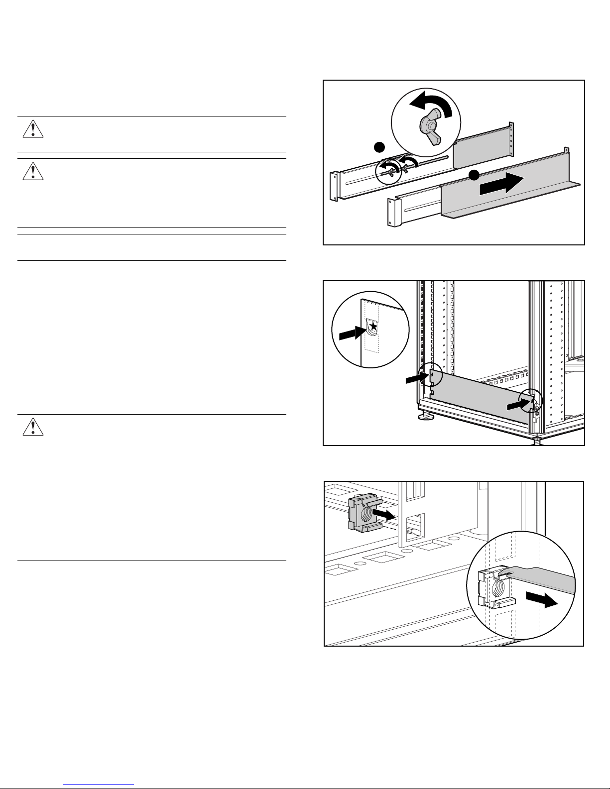
To mount the rails:
1. Loosen the wing nuts (1) and extend the brackets to the desired
length (2). Tighten the wing nuts slightly to stabilize
the bracket.
1
2
2. Use the rack template tool to measure and mark the screw
locations on the front and rear of the rack.
Mounting the Rails
The UPS must be mounted on the fixed rails supplied with the
UPS. Before beginning this installation process, review and adhere
to the following precautions.
WARNING: To prevent personal injury, verify that the rack
containing the UPS is stable. The following conditions must be
met:
• The leveling feet are extended to the floor.
• The full weight of the rack rests on the leveling feet.
• The stabilizing feet are attached to the rack if it is a
single-rack installation.
• The racks are coupled together if it is a multi-rack
installation.
• Only one component should be extended at a time. A rack
may become unstable if more than one component is
IMPORTANT: Power down the UPS to safely perform the following tasks.
extended for any reason.
3. Use the cage nut tool to install the cage nuts in the rear
rack-mounting rails.
Page 4

4. Insert the screws supplied in the UPS kit through each
rack-mounting rail and into the front of each rack.
5. Insert the screws into the back of each rail and through the cage
nuts that were installed in step 3.
6. Install the rear stabalization bracket.
Installing the UPS in the Rack
Before attempting to install the UPS, review and adhere to all
warnings provided in the “Important Safety Information” section
of this document.
To install the UPS in the rack:
1. With one person on each side of the carton, remove the UPS
chassis using the lift-out tray.
2. Gently lower the chassis to the floor in front of the rack.
3. Cut the band holding the chassis, freeing it from the
lift-out tray.
4. With one person on each side, lift the chassis to rail level and
slide it into place on the mounting rail.
5. Attach the chassis to the rack using the screws and the cage
nuts supplied with the rack.
NOTE: After installing the UPS chassis, insert additional screws for support
if any screw holes are unoccupied.
Completing the UPS Assembly
Connecting the Communications Port
The UPS includes a communications port that allows the unit to
exchange data with the host computer.
IMPORTANT: Power management software requires the communications
port to be appropriately cabled to the host computer.
Connect the UPS/computer interface cable (supplied) from the
communications port on the UPS to the appropriate
communications port on the host computer.
CAUTION: Use only the specific cable supplied with the UPS to
connect the communications port to the host computer.
Page 5

Connecting the Network Transient
Protector
The Network Transient Protector allows the UPS to protect a
communications device from surges.
IMPORTANT: To avoid damaging the equipment, use the Network
Transient Protector with a standard telephone line only, not with a
digital PBX.
4. Replace the connector block in the REPO port.
1
2
Item Description
1 Network Transient Protector “IN” jack
2 Network Transient Protector “OUT” jack
Connecting the REPO Port
WARNING: If the UPS is to be installed in a computer equipment
room, it must be connected to a REPO circuit. The REPO port is
designed to meet the requirements stated in National Electrical
Code (NFPA 70) Articles 645-10 and 645-11.
The REPO port allows power to the UPS output receptacles to be
switched off from a remote location.
To activate the REPO port:
1. Install a suitable switch at the required remote location.
2. Remove the connector block from the REPO port.
IMPORTANT:
• The REPO port must meet the requirements of the NFPA Articles
645-10 and 645-11 for a disconnecting means.
• The remote switch must be in the Off (open) position to enable power
to the output receptacles.
Connecting the Ground Bonding Screw
The ground bonding screw on the rear of the unit is provided as an
attachment point for conductors. Use the ground bonding screw if
the rack contains any conductors for the purpose of functional
grounding or bonding of ungrounded metal parts.
To connect the ground bonding screw:
1. Remove the ground bonding screw.
3. Wire the connector block using stranded, non-shielded wire
(AWG #22 - #18, or equivalent).
2. Attach the grounding cable and secure the ground
bonding screw.
Page 6

Connecting the UPS to Utility Power
Connect the UPS to a grounded utility power outlet.
WARNING: To prevent personal injury from electric shock or
damage to the equipment:
• Plug the input line cord into a grounded (earthed) electrical
outlet that is installed near the equipment and is easily
accessible.
• Do not disable the grounding plug on the input line cord. The
grounding plug is an important safety feature.
• Do not use extension cords.
Connecting Devices to the UPS
Before connecting devices, verify the UPS will not overload by
checking that the ratings of the devices do not exceed the UPS
capacity. Evenly distribute connected devices throughout all
load segments.
After verifying that the UPS will not overload, connect the power
cords from the devices to the appropriate output receptacles of
the UPS.
CAUTION: Do not plug laser printers into the UPS. The
instantaneous current drawn by this type of printer may overload
the UPS.
Powering up the UPS
To power up the UPS:
1. Connect the UPS to utility power using the input power cord.
The UPS automatically initiates a self-test. If the self-test is
completed successfully, the UPS enters Standby mode.
2. Check the front panel LED display. The Utility LED should be
flashing green. The load segments are not energized.
1
2
3
4
5
6
7
8
9
10
14
15
13
11 A
12
• Utility LED (5):
Flashing Red – Utility input voltage is outside the +20% to
-30% configured nominal range.
Green – Utility voltage is present and output is on or utility
voltage has returned to the voltage range that was
configured (UPS is supplying utility power and audible
alarm should be reset).
Flashing Green – Utility voltage is present and output is off.
UPS is in Standby mode. Batteries charge if needed.
• Overload LED (6): Red – UPS load exceeds maximum power
available.
• 76% to 100% load LED (7): Green – UPS load is
approximately 76% to 100% of maximum power.
• 51% to 75% load LED (8): Green – UPS load is approximately
51% to 75% of maximum power.
• 26% to 50% load LED (9): Green – UPS load is approximately
26% to 50% of maximum power.
• 0% to 25% load LED (10): Green – UPS load is approximately
0% to 25% of maximum power.
Refer to the UPS user guide for more information on the front
panel LED display and for procedures on configuring the UPS.
IMPORTANT: If any of the front panel LEDs are red (indicating an alarm
condition), press the Test/Alarm Reset button to clear the red LEDs. If this
does not clear the LEDs, refer to the UPS user guide for more information.
Charging the Batteries
With the UPS in Standby mode, allow the batteries to charge
before putting the UPS into service.
IMPORTANT: The battery pack charges to:
• 90% of its capacity within 3 hours.
• 100% of its capacity within 48 hours.
Charge the batteries for at least 24 hours before supplying backup power to
the devices.
Placing the UPS in Operate Mode
Press and hold the On button (1) until the Utility LED (2) turns
solid green, indicating that power is available at the UPS output
receptacles. The UPS acknowledges compliance with a short beep.
2
1 General Alarm 9 26% to 50% load
2 On Battery 10 0% to 25% load
3 Bad Battery 11 Configure Mode On LED
4 Site Wiring Fault Indicator 12 Configure button
5 Utility LED 13 Test/Alarm Reset button
6 Overload LED 14 Standby button
7 76% to 100% load 15 On button
8 51% to 75% load A Voltage configuration panel
NOTE: The Configure Mode On LED, the Configure button, and the voltage
configuration panel are accessible only when the front bezel is removed.
1
100%
25%
Page 7

Shutting Down the System
To shut down the system:
1. Shut down all load devices.
2. Press the Standby button to take the UPS out of Operate mode.
Power to the load receptacles ceases.
3. Disconnect the UPS from utility power.
4. Wait at least 60 seconds while the UPS internal
circuitry discharges.
For more information, refer to the HP website at
www.hp.com/products/ups
 Loading...