

Page 1

Maintenance and Service Guide
HP Pro All-in-One ms218/219
Page 2

© Copyright 2009, 2011 Hewlett-Packard
Development Company, L.P. The
information contained herein is subject to
change without notice.
Microsoft and Windows are trademarks of
Microsoft Corporation in the U.S. and other
countries.
The only warranties for HP products and
services are set forth in the express
warranty statements accompanying such
products and services. Nothing herein
should be construed as constituting an
additional warranty. HP shall not be liable
for technical or editorial errors or omissions
contained herein.
This document contains proprietary
information that is protected by copyright.
No part of this document may be
photocopied, reproduced, or translated to
another language without the prior written
consent of Hewlett-Packard Company.
Maintenance and Service Guide
Second Edition (November 2011)
First Edition (December 2009)
Document Part Number: 602765-002
Page 3

About This Book
WARNING! Text set off in this manner indicates that failure to follow directions could result in bodily
harm or loss of life.
CAUTION: Text set off in this manner indicates that failure to follow directions could result in
damage to equipment or loss of information.
NOTE: Text set off in this manner provides important supplemental information.
iii
Page 4

iv About This Book
Page 5

Table of contents
1 Components .................................................................................................................................................... 1
Rear components ................................................................................................................................. 1
Front and right side .............................................................................................................................. 2
2 Spare Parts ...................................................................................................................................................... 3
Processor and system board ................................................................................................................ 3
Drives and memory .............................................................................................................................. 3
Keyboards and Mice ............................................................................................................................. 4
Cables .................................................................................................................................................. 4
Misc Parts ............................................................................................................................................. 5
3 Removal and Replacement Procedures ....................................................................................................... 6
Preparing to disassemble the computer ............................................................................................... 6
Replacing the Keyboard or Mouse ....................................................................................................... 7
Memory ................................................................................................................................................ 9
Stand .................................................................................................................................................. 12
Hard drive ........................................................................................................................................... 14
Optical drive ....................................................................................................................................... 17
Back cover .......................................................................................................................................... 19
System board shield ........................................................................................................................... 20
Speakers ............................................................................................................................................ 20
Webcam ............................................................................................................................................. 21
WLAN module .................................................................................................................................... 22
Fan ..................................................................................................................................................... 23
Thermal module ................................................................................................................................. 24
Processor ........................................................................................................................................... 26
System board ..................................................................................................................................... 27
4 Computer Setup (F10) Utility ....................................................................................................................... 29
Computer Setup (F10) Utilities ........................................................................................................... 29
Using Computer Setup (F10) Utilities ................................................................................ 29
v
Page 6

Computer Setup—Main ..................................................................................................... 30
Computer Setup—Advanced ............................................................................................. 31
Computer Setup—Power ................................................................................................... 32
Computer Setup—Boot ...................................................................................................... 32
Computer Setup—Exit ....................................................................................................... 33
BIOS updates ..................................................................................................................................... 33
5 Software Troubleshooting ........................................................................................................................... 34
Updating Drivers ................................................................................................................................. 34
Microsoft System Restore .................................................................................................................. 34
Software Program and Hardware Driver Reinstallation ...................................................................... 35
Creating data backup discs ................................................................................................................ 36
Clearing CMOS and password settings ............................................................................................. 36
Troubleshooting .................................................................................................................................. 39
Computer does not start .................................................................................................... 39
Power ................................................................................................................................. 39
Display ............................................................................................................................... 40
Keyboard and mouse (with cable) ..................................................................................... 40
Wireless keyboard and mouse .......................................................................................... 42
Audio and speakers ........................................................................................................... 43
Internet access .................................................................................................................. 44
CD and DVD players ......................................................................................................... 44
Video .................................................................................................................................. 46
Hardware installation ......................................................................................................... 46
Performance ...................................................................................................................... 47
Memory card reader .......................................................................................................... 48
6 System Recovery .......................................................................................................................................... 49
Creating Recovery Discs .................................................................................................................... 49
Choosing Recovery Discs .................................................................................................................. 49
System Recovery Options .................................................................................................................. 50
System recovery from the Windows 7 Start menu ............................................................. 50
System recovery at system startup .................................................................................... 51
Starting system recovery from user-created recovery discs .............................................. 51
Index ................................................................................................................................................................... 53
vi
Page 7

1 Components
Rear components
Item Item Component
A Memory card reader Built-in memory card reader to read a memory card. Supported formats include:
B Audio line out Connect external 2.0 and 2.1 powered speakers.
C Memory card reader LED Indicates card reader activity.
D USB 2.0 ports (2) Connect USB devices (USB 2.0) such as printers, external hard disk drives, digital
E USB 2.0 ports (4) Connect USB devices (USB 2.0) such as printers, external hard disk drives, digital
F Microphone jack Connect an external microphone to the port.
G Headphone jack Produces sound when connected to optional powered stereo speakers,
Extreme Digital (xD), Secure Digital (SD), Secure Digital High-Capacity (SDHC),
MultiMediaCard (MMC), Memory Stick (MS), and Memory Stick Pro (MS Pro)
memory cards.
Additional media cards can be supported by using an adapter sleeve (purchased
separately): Mini SD, RS-MMC, Micro SD, MS-Duo, and MS Pro Duo.
cameras, and MP3 players.
cameras, and MP3 players.
headphones, ear buds, a headset, or television audio.
NOTE: When a device is connected to the headphone jack, the computer
speakers are disabled.
Rear components 1
Page 8

H Ethernet (Local Area
Network [LAN]) port
I Power connector Plug the power adapter into your computer.
Front and right side
Connect to the Internet through a wired network.
Item Item Component
J Webcam Create videos and snapshots that you can view, send by e-mail, and upload to
K Built-in microphone Record sound for webcam videos and for video chats online.
L Optical disc emergency
eject
M Optical disc drive and
LED
N Optical disc eject button Press this button to open the optical disc drive to insert or remove a disc.
O Brightness up Press this button for a brighter screen display.
P Brightness down Press this button to dim the screen display.
Q Hard disk drive LED Indicates hard disk drive activity.
R Power status LED Indicator light is blue when computer is on; the light is off when computer is in
S Built-in speakers Use the built-in stereo speakers for a powerful media experience when listening to
T Power/Standby button Press the button to turn on your computer or put it in Sleep mode.
video sharing sites. Use the built-in webcam and microphone for video chats
(Internet access required).
Insert a small pin to eject a disc when the optical disc Eject button does not work.
Watch your favorite DVDs, or listen to your CD collection. Burn CDs and DVDs.
The LED indicates whether there is a disc in the drive.
sleep or hibernate mode.
music, or when watching your home videos and DVDs.
2 Chapter 1 Components
Page 9

2Spare Parts
See the following available spare parts for the HP Pro All-in-One.
Processor and system board
Description Spare Part Number
System board
VT538AA or other 5.X BIOS only 597920-001
all 6.X BIOS units, 2010 and up 641326-001
Processor
AMD Athlon M2 3250e processor (1.5-GHz, 1-MB L2 cache) 597923-001
Drives and memory
Description Spare Part Number
DVD drive, Slim Tray, 8x Supermulti with Lightscribe 597927-001
500 GB hard drive, 7200 rpm 595170-001
320 GB hard drive, 7200 rpm 505914-001
250 GB hard drive, 7200 rpm 595171-001
160 GB hard drive, 7200 rpm 457547-001
Memory module, 2 GB (PC6400, DDR2-800) 505915-001
Memory module, 1 GB (PC6400, DDR2-800) 599326-001
Processor and system board 3
Page 10

Keyboards and Mice
Description Spare Part Number
Keyboard (Blue, USB)
Latin American Spanish 597932-161
Brazilian 597932-201
U.S./Pape 597932-371
French Canadian 597932-121
Keyboard (Blue, wireless, 2.4 GHz)
U.S./Pape 618799-371
S-Chinese 618799-AA1
Taiwan/T-Chinese 618799-AB1
Korean 618799-AD1
Mouse (Blue, wireless)
Optical, USB 596410-001
Wireless, 2.4 GHz 596412-001
Cables
Description Spare Part Number
Hard drive cable 638937-001
Optical drive cable 638938-001
Inverter power cable 638939-001
Webcam cable 638940-001
Power button cable 638941-001
Optical drive eject/brightness cable 638942-001
LCD cable 597921-001
4 Chapter 2 Spare Parts
Page 11

Misc Parts
Description Spare Part Number
802.11b/g WLAN PCIe adapter 597929-001
Thermal module, UMA 597924-001
Thermal module, MXM 597925-001
Fan 597926-001
Webcam module 597928-001
Speaker, right 597930-001
Speaker, left 597931-001
Power adapter, 120W 597922-001
Power button/LED side board 627711-001
Inverter board 627712-001
Misc Parts 5
Page 12

3 Removal and Replacement Procedures
The following sections provide information about disassembling various components of the HP Pro
All-in-One.
Preparing to disassemble the computer
To avoid injury and equipment damage, always complete the following steps in order, when opening
the HP Pro All-in-One.
1. Remove all media (CD, DVD, etc.) from the computer.
2. Shut down the computer.
3. After the system has completely shut down, disconnect the power adapter from the back of the
HP Pro All-in-One.
4. Disconnect all other attached cables from the back of the computer.
5. Place the computer face down on a soft flat surface. HP recommends that you set down a
blanket, towel, or other soft cloth to protect the touch screen surface from scratches or other
damage.
WARNING! Beware of sharp edges inside the chassis.
6 Chapter 3 Removal and Replacement Procedures
Page 13

Replacing the Keyboard or Mouse
1. Leave the computer on.
2. If you are replacing the wireless mouse, remove the old receiver and plug the new receiver into
the back of the computer. Skip this step if you are replacing the keyboard only.
3. Remove the tab from the battery compartment on the bottom of the mouse and/or the keyboard.
This activates the pre-installed battery.
Replacing the Keyboard or Mouse 7
Page 14

4. If you are replacing the mouse and it has a power switch on the bottom, turn on the mouse
power switch (A). The keyboard does not have a power switch, so you can skip this step if you
are installing the keyboard only.
5. Press the blue connect button on the bottom of the keyboard (B) and/or mouse (C) for 5 to 10
seconds. The blue activity LED on the wireless receiver illuminates when the synchronization
command has been received and goes off when synchronization is complete.
NOTE: If the synchronization does not work, remove and then re-insert the wireless receiver from
the back of the computer and synchronize the keyboard and/or mouse again.
8 Chapter 3 Removal and Replacement Procedures
Page 15

Memory
1. Prepare the computer for disassembly (see Preparing to disassemble the computer on page 6).
2. Locate the memory compartment in the upper right corner of the computer.
3. Lift up the rubber cover over the screw.
Memory 9
Page 16

4. Remove the Phillips screw that secures the cover to the computer.
5. Slide the memory compartment cover off.
10 Chapter 3 Removal and Replacement Procedures
Page 17

6. Open both latches of the memory module socket (1), and remove the memory module from the
socket (2).
NOTE: If you are removing both cards, you must remove the upper one before removing the
lower one.
To install a memory module, reverse the removal procedures.
Memory 11
Page 18

Stand
1. Prepare the computer for disassembly (see Preparing to disassemble the computer on page 6).
2. Use a flathead screwdriver to open the cover on the back of the computer behind the stand.
3. Use a Phillips screwdriver to remove the three screws that secure the stand to the computer.
12 Chapter 3 Removal and Replacement Procedures
Page 19

4. Slide the stand assembly down and out to remove it.
To install the stand, reverse the removal procedures.
Stand 13
Page 20

Hard drive
1. Prepare the computer for disassembly (see Preparing to disassemble the computer on page 6).
2. Lift up the rubber screw cover.
3. Use a Phillips screwdriver to remove the hard disk drive cover screw.
14 Chapter 3 Removal and Replacement Procedures
Page 21

4. Slide the hard disk drive cover off.
5. Loosen the screw at the front of the hard disk drive cage.
Hard drive 15
Page 22
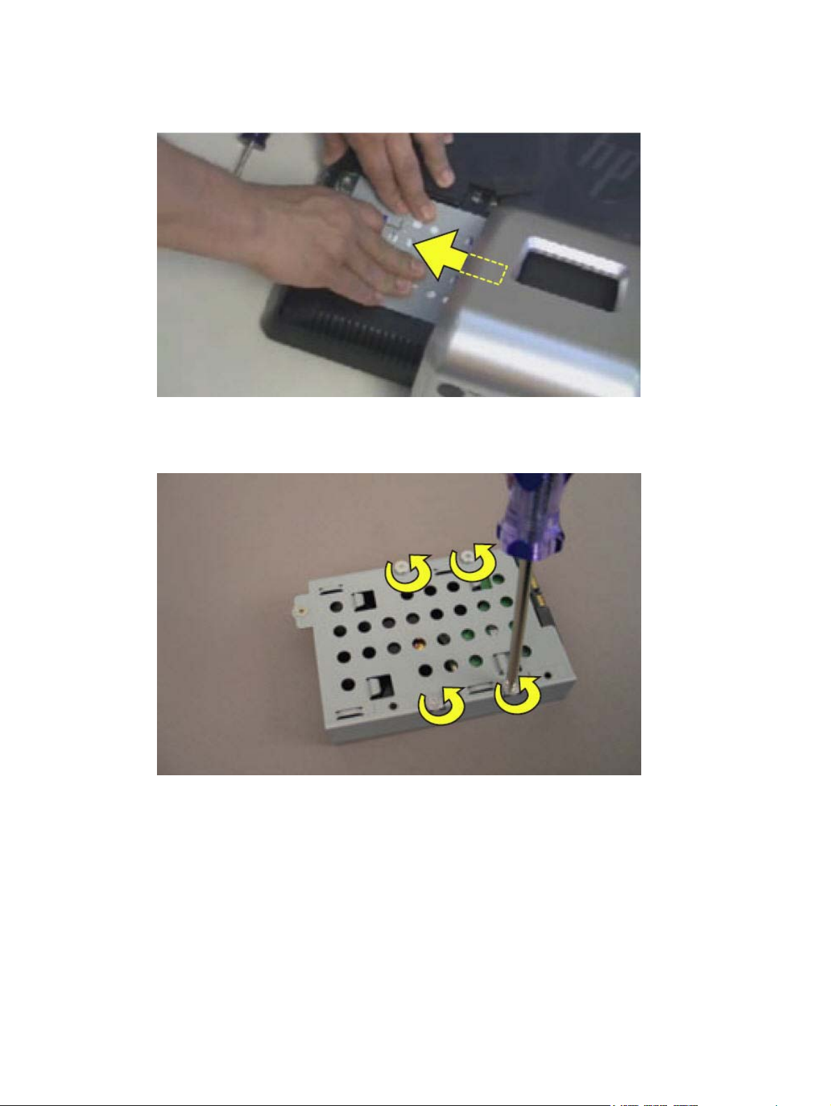
6. Lift up the metal handle on the hard disk drive cage and pull it firmly toward you to remove the
hard disk drive cage from its bay.
To remove the hard drive from the hard drive cage:
1. Remove the four screws that secure the hard drive into the hard drive cage.
2. Remove the drive from the cage.
16 Chapter 3 Removal and Replacement Procedures
Page 23

Optical drive
1. Prepare the computer for disassembly (see Preparing to disassemble the computer on page 6).
2. Lift up the screw cover and move it out of the way.
3. Use a Phillips screwdriver to remove the optical drive screw.
Optical drive 17
Page 24

4. Insert a small flathead screwdriver gently into the notch and use a levering motion to disengage
the optical drive assembly.
5. Pull the optical drive assembly out of the computer.
To install an optical drive, reverse the removal procedures.
18 Chapter 3 Removal and Replacement Procedures
Page 25

Back cover
1. Prepare the computer for disassembly (see Preparing to disassemble the computer on page 6).
2. Remove the stand (see
3. Remove the hard drive (see
4. Remove the optical drive (see
5. Remove the back cover by prying the back cover away from the front bezel, as follows:
a. Using your fingers at the outside seam between the back cover and front bezel, pry the
back cover away from the computer at the area near the stand mounting bracket.
b. Move around the bottom to the left side of the computer while prying the cover off the
computer.
c. After you pry the cover off near the optical drive, the cover should release from the
computer.
NOTE: To avoid breaking parts of the back cover or computer, make sure the tabs on the
back cover and slots on the computer are clearly separated before lifting the cover off the
computer.
Stand on page 12).
Hard drive on page 14).
Optical drive on page 17).
To replace the back cover, reverse the removal procedures.
Back cover 19
Page 26

System board shield
1. Prepare the computer for disassembly (see Preparing to disassemble the computer on page 6).
2. Remove the stand (see
3. Remove the hard drive (see
4. Remove the optical drive (see
5. Remove the back cover (see
6. Remove the system board shield by removing the four screws and lifting it off the computer.
NOTE: The bottom right screw also secures a speaker grounding cable.
Stand on page 12).
Hard drive on page 14).
Optical drive on page 17).
Back cover on page 19).
To install the system board shield, reverse the removal procedures.
Speakers
1. Prepare the computer for disassembly (see Preparing to disassemble the computer on page 6).
2. Remove the stand (see
3. Remove the hard drive (see
4. Remove the optical drive (see
5. Remove the back cover (see
6. Remove the system board shield (see
7. Disconnect the speaker cable from the system board (1).
20 Chapter 3 Removal and Replacement Procedures
Stand on page 12).
Hard drive on page 14).
Optical drive on page 17).
Back cover on page 19).
System board shield on page 20).
Page 27

8. Disconnect the cables that connect the two speakers together (2), and remove the speaker
cable from the tape (3) the secures it to the computer.
9. Each speaker has two screws that secure the speaker to the computer. To remove either
speaker, remove the two screws (4), and then lift the speaker from the computer.
To install the speakers, reverse the removal procedures.
Webcam
1. Prepare the computer for disassembly (see Preparing to disassemble the computer on page 6).
2. Remove the stand (see
3. Remove the hard drive (see
4. Remove the optical drive (see
5. Remove the back cover (see
6. Remove the system board shield (see
Stand on page 12).
Hard drive on page 14).
Optical drive on page 17).
Back cover on page 19).
System board shield on page 20).
Webcam 21
Page 28

7. Disconnect the cable from the system board (1), and remove the cable from the clips on the
computer (2).
8. Remove the two screws that secure the webcam to the computer, and lift it off the computer.
To install the webcam, reverse the removal procedures.
WLAN module
1. Prepare the computer for disassembly (see Preparing to disassemble the computer on page 6).
2. Remove the stand (see
3. Remove the hard drive (see
4. Remove the optical drive (see
22 Chapter 3 Removal and Replacement Procedures
Stand on page 12).
Hard drive on page 14).
Optical drive on page 17).
Page 29

5. Remove the back cover (see Back cover on page 19).
6. Remove the system board shield (see
7. Remove the antenna cables (1) from the module.
8. Remove the screw (2) that secures the module to the system board.
NOTE: Some modules may be secured by two screws.
9. Lift the module out of the slot at an angle.
System board shield on page 20).
Fan
NOTE: The WLAN module has a notch to prevent incorrect installation.
To install the WLAN module, reverse the removal procedures.
1. Prepare the computer for disassembly (see Preparing to disassemble the computer on page 6).
2. Remove the stand (see
3. Remove the hard drive (see
4. Remove the optical drive (see
5. Remove the back cover (see
6. Remove the system board shield (see
7. Remove the four screws (1) that secure the fan to the system board, and then lift the fan partially
out of the computer.
Stand on page 12).
Hard drive on page 14).
Optical drive on page 17).
Back cover on page 19).
System board shield on page 20).
Fan 23
Page 30

8. Disconnect the fan cable from the system board (2), and then remove the fan from the computer.
To install the fan, reverse the removal procedures.
Thermal module
1. Prepare the computer for disassembly (see Preparing to disassemble the computer on page 6).
2. Remove the stand (see
3. Remove the hard drive (see
4. Remove the optical drive (see
5. Remove the back cover (see
6. Remove the system board shield (see
7. Remove the fan (see
8. Loosen the captive screws from the thermal module, as follows:
a. (1) Two screws for the chipset heat sink
b. (2) Four screws for the processor heat sink
c. (3) Two screws for the graphics card heat sink
Stand on page 12).
Hard drive on page 14).
Optical drive on page 17).
Back cover on page 19).
System board shield on page 20).
Fan on page 23).
24 Chapter 3 Removal and Replacement Procedures
Page 31

9. Lift the thermal module off the system board.
To install the system board, reverse the removal procedures.
Note the following thermal module features:
(1) Radiator that fits into the fan assembly
●
(2) Heat sink for the chipset
●
(3) Heat sink for the processor
●
(4) Heat sink for the graphics card
●
Thermal module 25
Page 32

Make sure the heat sinks have new thermal material when installing a thermal module.
Processor
1. Prepare the computer for disassembly (see Preparing to disassemble the computer on page 6).
2. Remove the stand (see
3. Remove the hard drive (see
4. Remove the optical drive (see
5. Remove the back cover (see
6. Remove the system board shield (see
7. Remove the fan (see
8. Remove the thermal module (see
9. Rotate the locking lever to its full open position (1).
Stand on page 12).
Hard drive on page 14).
Optical drive on page 17).
Back cover on page 19).
System board shield on page 20).
Fan on page 23).
Thermal module on page 24).
26 Chapter 3 Removal and Replacement Procedures
Page 33

10. Carefully lift the processor from the socket (2).
CAUTION: Do NOT handle the pins in the processor socket. These pins are very fragile and
handling them could cause irreparable damage. Once pins are damaged it may be necessary to
replace the system board.
CAUTION: The heat sink must be installed within 24 hours of installing the processor to
prevent damage to the processor’s solder connections.
To install a new processor:
1. Place the processor in its socket and close the retainer.
2. Secure the locking lever.
If reusing the existing heat sink, go to step 3.
If using a new heat sink, go to step 5.
3. If reusing the existing heat sink, clean the bottom of the heat sink with the alcohol pad provided
in the spares kit.
4. Apply the thermal material provided in the spares kit to the top of the processor and install the
heat sink atop the processor.
5. If using a new heat sink, remove the protective covering from the bottom of the heat sink and
place it in position atop the processor.
System board
1. Prepare the computer for disassembly (see Preparing to disassemble the computer on page 6).
2. Remove the stand (see
3. Remove the hard drive (see
Stand on page 12).
Hard drive on page 14).
4. Remove the optical drive (see
Optical drive on page 17).
System board 27
Page 34

5. Remove the back cover (see Back cover on page 19).
6. Remove the system board shield (see
7. Remove the WLAN module (see
8. Remove the fan (see
Fan on page 23).
9. Remove the thermal module (see
System board shield on page 20).
WLAN module on page 22).
Thermal module on page 24).
10. Disconnect all remaining connectors.
11. Remove the eight screws that secure the system board to the computer.
12. Lift the system board out of the computer.
To install the system board, reverse the removal procedures.
28 Chapter 3 Removal and Replacement Procedures
Page 35

4 Computer Setup (F10) Utility
Computer Setup (F10) Utilities
Access the BIOS Setup Utility by pressing the F10 button during startup. Use Computer Setup (F10)
Utility to do the following:
Change factory default settings.
●
Set the system date and time.
●
Set, view, change, or verify the system configuration, including settings for processor, graphics,
●
memory, audio, storage, communications, and input devices.
View processor and memory settings
●
Modify the boot order of bootable devices such as hard drives, diskette drives, optical drives, or
●
USB media.
Run hard drive self-tests.
●
Establish a supervisor password that controls access to Computer Setup (F10) Utility and the
●
settings described in this section.
Using Computer Setup (F10) Utilities
Computer Setup can be accessed only by turning the computer on or restarting the system.
To access the Computer Setup Utilities menu, complete the following steps:
1. Turn on or restart the computer.
2. As soon as the computer is turned on, press F10 before the system boots to the operating
system to enter Computer Setup. Press Enter to bypass the title screen, if necessary.
NOTE: If you do not press F10 at the appropriate time, you must restart the computer and
again press F10 before the unit boots to the operating system to access the utility.
3. The Computer Setup Utility screen is divided into menu headings and actions.
Five menu headings appear on the Computer Setup Utility screen:
Main
●
Advanced
●
Boot
●
Computer Setup (F10) Utilities 29
Page 36

Power
●
Exit
●
Use the arrow keys to select the appropriate heading, then press Enter. Use the arrow (up and
down) keys to select the option you want, then press Enter. To return to the previous screen,
press Esc.
4. To apply and save changes, press the F10 key.
If you have made changes that you do not want applied, press the F5 key to return to the default
values.
CAUTION: Do NOT turn the computer power OFF while the ROM is saving the Computer Setup
(F10) changes because the CMOS could become corrupted. It is safe to turn off the computer only
after exiting the F10 Setup screen.
Table 4-1 Computer Setup (F10) Utility Main Menu
Heading Table
Main
Advanced
Boot
Power
Exit
Computer Setup—Main
NOTE: Support for specific Computer Setup options may vary depending on the hardware
configuration.
Table 4-2 Computer Setup—Main
Option Description
System Time Allows you to set system time.
System Date Allows you to set system date.
Language Allows you to select language.
Computer Setup—Main on page 30
Computer Setup—Advanced on page 31
Computer Setup—Boot on page 32
Computer Setup—Power on page 32
Computer Setup—Exit on page 33
30 Chapter 4 Computer Setup (F10) Utility
Page 37

Table 4-2 Computer Setup—Main (continued)
1st Drive
2nd Drive
System Information (view only)
For each, allows you to:
● Capacity
Transfer Mode
●
Smart Support:
●
◦ SMART Status Check
◦
◦
Installed Memory
●
Memory Bank 1
●
● Memory Bank 2
BIOS Revision
●
Core Version
●
Model Number
●
Product Number
●
● Build ID
SMART Short Self-Test
SMART Extended Self-Test
Computer Setup—Advanced
NOTE: Support for specific Computer Setup options may vary depending on the hardware
configuration.
WARNING! Setting items on this menu to incorrect values may cause your system to malfunction.
Table 4-3 Computer Setup—Advanced
Option Description
CPU Type (view only)
CPU Speed (view only)
Cache RAM (L2) (view only)
SATA1 Controller Allows you to disable/enable the SATA Controller.
SATA1 Controller
Mode
Onboard LAN Allows you to disable/enable onboard LAN controller.
Onboard LAN Boot
ROM
If SATA1 Controller is enabled, allows you to set the mode to:
● IDE
AHCI
●
Allows you to disable/enable the boot ROM of the onboard LAN chip.
Computer Setup (F10) Utilities 31
Page 38

Table 4-3 Computer Setup—Advanced (continued)
Change Supervisor
Password
Change User
Password
Onboard Audio Allows you to set the on-board audio to:
Allows you to change the supervisor password.
Allows you to change the user password.
● Enabled
●
Computer Setup—Power
NOTE: Support for specific Computer Setup options may vary depending on the hardware
configuration.
Table 4-4 Computer Setup—Power
Option Description
After AC Power
Failure
Allows you to select system restart behavior after power loss:
●
●
● Auto
Disabled
Stay Off
Power On
XD (Execute Disable) Disables/enables the processor's XD feature.
Virtualization
Technology
Allows you to disable/enable Virtualization Technology.
Computer Setup—Boot
NOTE: Support for specific Computer Setup options may vary depending on the hardware
configuration.
Table 4-5 Computer Setup—Boot
Option Description
Boot-time Diagnostic
Screen
(Boot Device Priority)
1st Boot Device
2nd Boot Device
3rd Boot Device
4th Boot Device
Disables/enables POST diagnostic messages display.
Allows you to specify which device groups will boot first, second, third, and fourth or to disable any
of the four:
● CD-ROM Group
●
●
● Network Boot Group
HDD Group
Floppy Group
NOTE: MS-DOS drive lettering assignments may not apply after a non-MS-DOS operating
system has started.
32 Chapter 4 Computer Setup (F10) Utility
Page 39

Table 4-5 Computer Setup—Boot (continued)
Floppy Group Boot
Priority
CD-ROM Group Boot
Priority
HDD Group Boot
Priority
Network Group Boot
Priority
Computer Setup—Exit
NOTE: Support for specific Computer Setup options may vary depending on the hardware
configuration.
Table 4-6 Computer Setup—Exit
Option Description
Exit Saving Changes Press Enter to exit saving changes.
Exit Discarding
Changes
Load Setup Defaults Press Enter to load setup defaults.
Specifies boot device priority within removable devices.
Specifies boot device priority within CD/DVD drives.
Specifies boot device priority within hard drives.
Specifies boot device priority within bootable network devices.
Press Enter to exit discarding changes.
Discard Changes Press Enter to discard changes.
Save Changes Press Enter to save changes.
BIOS updates
HP periodically releases system BIOS updates, which are available from the HP website. These
updates often contain fixes for known issues in the BIOS.
To find out whether a PC needs a BIOS update, compare the current BIOS version number against
the latest version available for download. To determine the current BIOS version, you should perform
the following steps:
1. Click Start, and then select Shut Down.
2. Select Restart, and then click OK.
3. When the first screen displays, press F10 to enter Setup. The BIOS revision number is listed on
the Main menu.
4. Write down the current BIOS version that is listed.
5. To exit Setup, press Esc, select Yes, and then press Enter.
BIOS updates 33
Page 40

5 Software Troubleshooting
Your computer uses the operating system and installed software programs during normal operation. If
your computer works improperly or stops because of the software, you may be able to repair it.
Some software repairs are as simple as restarting your computer, and others require performing a
system recovery from files on your hard disk drive.
Updating Drivers
A driver is a software program that enables your computer to communicate with an attached device,
such as a printer, hard disk drive, mouse, or keyboard.
Complete the following procedure to update a driver, or to revert to an earlier version of the driver if
the new one does not solve your problem:
1. Click the Start button.
2. Type Device Manager into the Start Search box, and then click Device Manager to open the
Device Manager window.
3. Click the plus sign (+) to expand the type of device for which you want to update or rollback, (for
example, DVD/CD-ROM drives).
4. Double-click the specific item (for example, HP DVD Writer 640b).
5. Click the Driver tab.
6. To update a driver, click Update Driver, and follow the on-screen instructions.
– or –
To revert to an earlier version of a driver, click Rollback Driver, and follow the on-screen
instructions.
Microsoft System Restore
Microsoft Windows 7 includes a feature that enables you to restore your computer configuration to a
configuration that was in use before the current software problem existed. The feature does this by
creating a restore point where it records the computer settings at that time and date.
When a new program is installed, the operating system automatically creates a restore point before it
adds the new software. You can also set restore points manually.
If you experience a problem that you think may be due to software on your computer, use System
Restore to return the computer to a previous restore point.
34 Chapter 5 Software Troubleshooting
Page 41

NOTE: Always use this System Restore procedure before you use the system recovery program.
To start a System Restore:
1. Close all open programs.
2. Click the Start button, right-click Computer, and then click Properties.
3. Choose System protection, System Restore, and then click Next.
4. Follow the on-screen instructions.
To manually add restore points:
1. Close all open programs.
2. Click the Start button, right-click Computer, and then click Properties.
3. Click System protection.
4. Under Protection Settings, select the disk for which you want to create a restore point.
5. Click Create.
6. Follow the on-screen instructions.
For more information about software restore points:
1. Click the Start button, and then click Help and Support.
2. Type system restore into the Search box, and then press Enter.
Software Program and Hardware Driver Reinstallation
If an individual factory-installed software program or hardware driver is damaged, you can reinstall it
by using the Recovery Manager program (select models only).
NOTE: Do not use the Recovery Manager program to reinstall software programs that came on
CDs or DVDs included in the computer box. Reinstall these programs directly from the CDs or DVDs.
Before you uninstall a program, be sure you have a way to reinstall it. Check that it is still available
from where you initially installed it (for example, discs or the Internet). Or check that the program is in
the list of programs you can reinstall from the Recovery Manager.
To check the list of installable programs in the Recovery Manager:
1. Click the Start button, All Programs, Recovery Manager, and then click Recovery Manager. If
prompted, click Yes to allow the program to continue.
2. Under I need help immediately, click Software Program Reinstallation.
3. Click Next at the Welcome screen.
A list of programs opens. Check whether your program is there.
Software Program and Hardware Driver Reinstallation 35
Page 42

To uninstall a program:
1. Close all software programs and folders.
2. Uninstall the damaged program:
a. Click the Start button, and then click Control Panel.
b. Under Programs, click Uninstall a program.
c. Select the program you want to remove, and then click Uninstall.
d. Click Yes if you want to continue with the uninstall process.
To reinstall a program using the Recovery Manager:
1. Click the Start button, click All Programs, click Recovery Manager, and then click Recovery
Manager.
2. Click Software Program Reinstallation.
3. Click Next at the Welcome screen.
4. Choose the program you want to install, click Next, and follow the on-screen instructions.
5. When you have finished reinstalling, restart the computer.
NOTE: Do not skip this last step. You must restart the computer when you are finished recovering
software programs or hardware drivers.
Creating data backup discs
Use CD or DVD recording (or burning) software that is installed on your computer to create backup
discs of important information, including personal files, e-mail messages, and Web site bookmarks.
You can also move data to an external hard disk drive.
When writing data to a backup disc, use software that includes write verification functionality. This
feature compares the data on your hard disk drive with the data copied to the disc to ensure it is an
exact copy. Depending on your disc recording software, you may need to manually enable this
feature (refer to the software documentation).
If you encounter recording issues, try alternate media (different types or brands). Also, use the
Windows Explorer tool to view your files and verify content was copied over. To open Windows
Explorer, right-click the Start button, and then click Explore.
Clearing CMOS and password settings
When the BIOS has been incorrectly configured, it is sometimes necessary to clear all CMOS
settings.
To clear the CMOS, perform the following steps:
36 Chapter 5 Software Troubleshooting
Page 43

CAUTION: Before attempting to remove or touch any parts from the motherboard, check that the
power cord is disconnected from the electrical outlet. Failing to do so can cause hardware damage
and even physical injury.
1. Shut down the operating system and turn off the computer and any external devices.
2. Disconnect the power cords of the computer and any external devices from the power outlet.
3. Disconnect any external devices that are connected to the computer.
4. Remove all components required to gain access to the system board.
5. Locate the solder points on the system board.
Clearing CMOS and password settings 37
Page 44

6. To clear CMOS, make a short on the two solder pads labeled CLEAR CMOS.
-or-
To clear CMOS, make a short on the two solder pads labeled PASSWORD.
7. Reassemble the computer.
8. Reconnect the external equipment.
9. Plug in the computer and turn on the power. Allow the operating system to start.
38 Chapter 5 Software Troubleshooting
Page 45

Troubleshooting
Computer does not start
Table 5-1 Computer does not start
Symptom Possible solution
Computer will not turn on or start. Ensure that the cables connecting the computer to the external power source are
Computer seems to be locked up
and is not responding.
plugged in properly.
When the cables connecting the computer to the external power source are plugged in
properly, and the wall outlet is functioning, the green power supply light on the back of
the computer should be on.
Test the wall outlet by connecting a different electrical device to it.
Incompatible memory (RAM) may have been installed. Reinstall the old memory to
return your computer to its original state. For instructions, refer to the Upgrading and
Servicing Guide.
Use the Windows Task Manager to close any programs not responding, or restart the
computer:
1. Press the Ctrl+Alt+Delete.
2. Click Start Task Manager.
3. Select the program that is not responding, and then click End Task.
If closing programs does not work, restart the computer:
1. Press the Ctrl+Alt+Delete.
2. Click the arrow next to the red Shut Down button, and then click Restart.
Or
1. Press and hold the On button for 5 or more seconds to turn off the computer.
Power
2. Press the On button to start the computer.
Table 5-2 Power
Symptom Possible solution
Error message: Invalid system
disk or Non-System disk or Disk
error.
Computer does not turn off when
the On button is pressed.
Computer shuts down
automatically.
When optical disc drive activity stops, remove the disc and press the spacebar on the
keyboard. The computer should start up.
Press and hold the On button until the computer turns off.
Check power settings.
The computer may be in an exceedingly hot environment. Let it cool down.
Ensure computer air vents are not blocked and internal fan is running. Note that your
computer may not have an internal fan.
Troubleshooting 39
Page 46

Display
Table 5-3 Display
Symptom Possible solution
Screen is blank, and power light
is not lit.
Screen is blank. Press the space bar on the keyboard or move the mouse to make the screen display
Images on the screen are too
large or too small, or the images
are fuzzy.
Reconnect the power plug to the back of the computer and to the wall outlet.
Press the On button on the front of the computer.
visible again.
Press the Esc key on the keyboard to resume from Sleep or Hibernate mode.
Press the On button to turn on the computer.
Adjust the monitor resolution setting in Windows 7:
1. Click the Start button, and then click Control Panel.
2. Under Appearance and Personalization, click Adjust Screen Resolution.
3. Adjust resolution as necessary, and then click Apply.
Keyboard and mouse (with cable)
Table 5-4 Keyboard and mouse (with cable)
Symptom Possible solution
Keyboard commands and typing
are not recognized by the
computer.
Turn off the computer by using the mouse, unplug and reconnect the keyboard to the
back of your computer, and then turn on your computer.
Mouse (with cable) does not work
or is not detected.
Cursor does not respond to
mouse movement.
Unplug and reconnect the mouse cable to your computer.
If the mouse is still not detected, turn off the computer, unplug and reconnect the mouse
cable, and then restart the computer.
Restart your computer by using the keyboard:
1. Press Alt+Tab to navigate to an open program.
2. Press Ctrl+S to save your changes in the selected program.
3. Repeat step 1 and step 2 to save changes in all open programs.
4. After saving changes in all open programs, press Ctrl+Esc to display the Windows
Start Menu.
5. Use the arrow keys to select the Arrow button next to Shut Down, select Shut
Down, and then press the Enter key on the keyboard.
6. After the shutdown is complete, unplug and reconnect the mouse connector to the
back of your computer, and then turn on your computer.
40 Chapter 5 Software Troubleshooting
Page 47

Table 5-4 Keyboard and mouse (with cable) (continued)
Cursor responds slowly, moves
only vertically or horizontally, or
does not track smoothly.
I cannot move the cursor using
the arrow keys on the number
key pad.
For an optical mouse:
● Clean the optical mouse: Gently wipe the light sensor lens on the bottom of the
mouse with a lint-free cloth (not paper).
Use a mouse pad, white sheet of paper, or other less reflective surface under the
●
mouse.
For detailed cleaning instructions, go to:
Select your country/region and language, search on your computer model number, and
then search on the keyword cleaning.
Press the Num Lock key to turn off the Num Lock light. The Num Lock light should not
be on if you want to use the arrow keys on the number key pad.
http://www.hp.com/support
Troubleshooting 41
Page 48

Wireless keyboard and mouse
Table 5-5 Wireless keyboard and mouse
Symptom Possible solution
Wireless keyboard or mouse
does not work or is not detected.
A Check for these problems:
Ensure you are using the wireless keyboard or wireless mouse within range of the
●
receiver, approximately 10 meters (32 feet) for normal use, and within 30 cm (12
inches) during initial setup or for resynchronization.
Check the LED on the mouse to indicate battery power level. When the mouse
●
powers up:
◦ If the LED is green, the mouse has full power.
If the battery level is low, the LED will be amber and will fade in and out 10
◦
times continuously.
If the battery level is below 2.0 V, the LED will not turn on, and the battery will
◦
need to be replaced.
Replace the batteries in the keyboard and mouse; do not use rechargeable
●
batteries: Turn the devices over, turn the mouse off, take off the battery cover,
remove the old batteries, and insert new alkaline batteries. Then turn on the mouse
and press the Connect button.
● Ensure the mouse is not in Suspend mode, which occurs after 20 minutes of
inactivity. Click the left mouse button to reactivate it.
B Resynchronize the keyboard and mouse to the receiver:
The receiver, wireless keyboard, and wireless mouse shown in the illustrations are
examples; your models may vary.
NOTE: During these steps, place the wireless keyboard and wireless mouse on the
same level as the receiver, within 30 cm (12 inches) of the receiver, and away from
interference from other devices.
1. Unplug and reconnect the receiver into a USB connector on the computer.
The receiver may have an LED light
2. Check that the mouse is on, and push and hold the Connect button on the
underside of the mouse for 5 to 10 seconds.
NOTE: The receiver connection session times out after 60 seconds. To ensure
the connection was established, and that the receiver did not time out instead,
move the mouse and check for response on the screen.
3. After the mouse connection is established, continue with the steps that follow to
repeat the procedure for the keyboard.
4. Push and hold the Connect button on the underside of the keyboard for 5 to 10
seconds.
42 Chapter 5 Software Troubleshooting
Page 49

Audio and speakers
Table 5-6 Audio and speakers
Symptom Possible solution
No sound is produced. Press the Mute button on the keyboard to see whether the Mute feature is enabled.
Or
1. Right-click the Volume icon on the taskbar, and then click Open Volume Mixer.
The Volume Mixer settings window opens.
2. If programs are muted, click the Mute button to unmute.
To increase the volume, click the Volume icon on the task bar, or use the keyboard
If you are using external speakers, make sure that you connected powered (active)
Turn off your computer, and then unplug and reconnect the external speakers. Ensure
To resume from Sleep mode, press the Sleep button (select models only), or press the
Unplug headphones if they are connected to your computer.
controls. Check the volume setting in your software program.
speakers and that they are turned on.
the external speakers are connected to a Line Out connector.
Esc key.
Troubleshooting 43
Page 50

Internet access
Table 5-7 Internet access
Symptom Possible solution
I cannot connect to the Internet. Contact your ISP for assistance.
Verify that you are using the proper cables for your Internet connection type.
Run the wireless setup wizard:
1. Click the Start button, and then click Control Panel.
2. Click Network and Internet, and then click Network and Sharing Center.
3. In the Network and Sharing Center window, click Set up a connection or network
to open the wizard.
4. Follow the on-screen instructions.
Use Device Manager to verify that the integrated WLAN device is installed on the
computer correctly:
1. Click the Start button.
2. Type Device Manager into the Start Search box, and then click Device
Manager.
3. Click Network adapters. The WLAN device should be listed here. The WLAN
device may include the term wireless, wireless LAN, or 802.11.
CD and DVD players
Table 5-8 CD and DVD players
Symptom Possible solution
The CD or DVD drive cannot read
a disc, or it takes too long to start.
4. Click the Start button.
5. Type Network and Sharing Center into the Start Search box, and then click
Network and Sharing Center to open the Network and Sharing Center window.
6. Click Connect to a network, and then follow the on-screen instructions.
Ensure the disc is inserted with the label facing out and centered in the tray.
Wait at least 30 seconds for the drive to determine the type of media.
Clean the disc with a disc cleaning kit, available from most computer stores.
The driver may be corrupted or outdated. For detailed information about restoring and
updating drivers, see “Updating drivers”.
44 Chapter 5 Software Troubleshooting
Page 51

Table 5-8 CD and DVD players (continued)
I cannot remove a CD or DVD. Turn on your computer, and press the Eject button nearest the drive to open the tray.
If you suspect a problem with the Eject button itself:
1. Click the Start button, and then click Computer.
2. Right-click the CD or DVD drive you want to open.
3. Select Eject from the menu.
4. If the disc is stuck, stick a pin in the hard eject button, a small pin hole on side of
the computer, to release it.
I cannot play a DVD movie on a
DVD player.
Ensure the disc is inserted with the label facing out and centered in the tray.
Verify that you are using the correct disc type (media) for the drive. Try a different brand
Ensure the disc is clean and undamaged. If recording stopped during a recording
Use the correct type of disc for the type of files you are recording.
When using a CD-R disc, ensure it is blank if recording music, and that it is blank or
Verify that you are using the correct disc type when you make a copy of a disc. Some
Select a slower write speed for the recording drive, if a slower speed is available.
The recording software may not let you add a track if it exceeds the available space on
Close all software programs and windows before recording.
Ensure you have enough available space on your hard disk drive to store a temporary
Your DVD player cannot play video files that were recorded onto the DVD as data files.
To play a movie properly, use a video recording program. Some video files may be
viewed on a computer, but not on a home DVD video player.
of disc.
session, the disc may be damaged; use a different disc.
appendable (with space to add more data files) if recording data.
recording programs can record only to the same disc type as the source. For example,
you can record a DVD only to a DVD+R/-R or a DVD+RW/-RW disc, and you can record
a CD only to a CD-R or a CD-RW disc.
your disc. You can make space available by removing one or more tracks from the list
before recording the files to the disc.
copy of the content.
Click the Start button, and then click Computer. Right-click the hard disk drive, and
then click Properties to view the available space.
If you are on a network, copy the files from a network drive to your hard disk drive first,
Close all programs and windows, and then restart your computer.
and then record them to disc.
Troubleshooting 45
Page 52

Video
Table 5-9 Video
Symptom Possible solution
Some video files do not play. Your file may be corrupt or in an unsupported format. Open the video file in a video
Codec error messages appear
when I try to play certain video
files.
Error message: Files Needed To
Display Video Are Missing or
Corrupt.
editor, and then resave the file in a supported format.
Open the file in Windows Media Player. Ensure Windows Media Player is configured to
automatically download codecs.
● If the correct codec is available, the file will play. Note that you must be connected
to the Internet to download the codec file.
If the correct codec is not available, check to see whether there is an update
●
available for Windows Media Player.
For more information, open Windows Media Player Help and search for codec.
1. Click the Start button.
2. Type Device Manager into the Start Search box, and then click Device
Manager to open the Device Manager window.
3. Click the plus sign (+) next to Sound, video and game controllers.
4. Right-click TV tuner (select models only), and then click Update Driver Software.
5. Select Search automatically for updated driver software.
6. Follow the instructions to update the driver.
7. If you are prompted, restart the computer.
Hardware installation
Table 5-10 Hardware installation
Symptom Possible solution
A new device is not recognized
as part of the system.
Install the device driver provided with the device, or download and install the driver from
the device manufacturer Web site.
You may need an updated driver for Windows. Contact the device vendor directly for an
update.
For HP peripheral devices, visit the HP Web site:
Ensure that all cables are properly and securely connected and that the pins in the cable
or connector are not bent.
Turn off the computer, turn on the external device, and then turn on the computer to
integrate the device with the computer.
Disable the automatic settings in the operating system for the new device, and choose a
basic configuration that does not cause a resource conflict.
You can also reconfigure or disable devices to resolve the resource conflict.
http://www.hp.com/support
46 Chapter 5 Software Troubleshooting
Page 53

Table 5-10 Hardware installation (continued)
A new device does not work. To install or uninstall a device driver, you must be logged in with administrative
A device does not work after
installing a new device.
privileges. If you need to switch users, click the Start button, click the Arrow button next
to Shut Down, and then click Switch User. Choose a user with administrative
privileges.
To resolve a device conflict, you may need to disable one of the devices or uninstall an
old device driver:
1. Click the Start button.
2. Type Device Manager into the Start Search box, and then click Device
Manager to open the Device Manager window.
3. Click the plus sign (+) next to the problem device and check for an exclamation
point in a yellow circle near the device icon. The exclamation point means there is
a device conflict or problem with the device. Exclamation points do not always
appear when a device is not working properly.
4. If you have removed a hardware device, but the device driver is still listed in the
Device Manager, this may be causing the device conflict. To uninstall the old driver
so that the new device driver works properly, right-click the device, click Uninstall,
and then click OK.
5. Right-click the name of the device, and then select Properties.
6. Click the General tab to see whether your device is enabled and working properly.
If it is available, click the Troubleshoot button, and follow the on-screen
instructions in the device troubleshooter wizard.
7. Restart the computer. Click the Start button, click the Arrow button next to Shut
Down, and then click Restart.
Performance
Table 5-11 Performance
Symptom Possible solution
Computer displays a processor
speed that is lower than
expected.
Software programs and files take
longer than expected to open or
respond.
This happens when the processor is automatically running in a lower power state,
because the applications running do not require the maximum processing power.
Verify that your system contains the processor you purchased. To verify, click the Start
button, right-click Computer, click Properties, and under the General tab check the
processor installed on your system.
If you created multiple user accounts on your computer, ensure other users are not
logged in. If there are multiple users logged in simultaneously, system resources must
be shared among them.
Troubleshooting 47
Page 54

Memory card reader
Table 5-12 Memory card reader
Symptom Possible solution
Memory card reader cannot read
the memory card.
Do not insert or remove memory cards when the memory card reader LED is flashing.
Doing so may cause data loss or permanent damage to the card reader.
Some memory cards have a Read/Write or a Security switch. Ensure the switch is set to
Write Enabled before you attempt to write data to the card.
Ensure the amount of stored data does not exceed the storage limit of the memory card.
Ensure the memory card is one of the supported types: Memory Stick (MS), Memory
Stick Pro (MS Pro), MultiMediaCard (MMC), Secure Digital (SD), Secure Digital HighCapacity (SDHC), or Extreme Digital (xD).
Additional media card types can be supported by use of an adapter sleeve: Mini Secure
Digital (Mini SD), Micro Secure Digital (Micro SD), Reduced-sized MultiMediaCard (RSMMC), Memory Stick Duo (MS Duo), or Memory Stick Pro Duo (MS Pro Duo).
Ensure the memory card is fully inserted into the slot and the LED is on.
Inspect the ends of the memory cards for dirt or material that closes a hole or spoils a
metal contact. Clean the contacts with a lint-free cloth and a small amount of isopropyl
alcohol. Replace the memory card if necessary.
48 Chapter 5 Software Troubleshooting
Page 55

6 System Recovery
System recovery completely erases and reformats the hard disk drive, deleting all data files you have
created. System recovery reinstalls the operating system, programs, and drivers. However, you must
reinstall any software that was not installed on the computer at the factory. This includes software that
came on CDs included in the computer accessory box, and software programs installed after
purchase.
Choose from the following methods for performing a System Recovery:
Recovery Image—Run the system recovery from a recovery image stored on your hard disk drive.
The recovery image is a file that contains a copy of the original factory-shipped software. To perform
a system recovery from the recovery image on your hard disk drive.
NOTE: The recovery image uses a portion of the hard disk drive that cannot be used for data
storage.
Recovery Discs—Run the system recovery from a set of recovery discs that you create from files
stored on your hard disk drive.
Creating Recovery Discs
Complete the procedure described in this section to create a set of recovery discs from the recovery
image stored on your hard disk drive. This image contains the operating system and software
program files that were originally installed on your computer at the factory.
You can create only one set of recovery discs for your computer. Furthermore, the recovery discs you
create can be used only with your computer.
Choosing Recovery Discs
To create recovery discs, your computer must have a DVD writer.
Use DVD+R or DVD-R blank media to create your system recovery discs.
●
You cannot use DVD+RW, DVD-RW, DVD+RW DL, DVD-RW DL, DVD+R DL, or DVD-R DL
●
discs to create recovery discs.
Use high-quality discs to create your set of recovery discs. The verification standard for the recovery
disc creation process is very high. You may see error messages such as Recording failure when
writing disc or Error detected during disc verification.
Your discs may be rejected if they are not defect-free. You will be prompted to insert a new blank disc
to try again. It is normal that some of your discs may be rejected.
Creating Recovery Discs 49
Page 56

The number of discs in the recovery disc set depends on your computer model (typically 1–3 DVD
discs). The Recovery Disc Creator program tells you the specific number of blank discs needed to
make the set.
The process takes some time to verify that the information written on the disc is correct. You can quit
the process at any time. The next time you run the program, it resumes where it left off.
To create recovery discs:
1. Close all open programs.
2. Tap the Start button, All Programs, Recovery Manager, and then tap Recovery Disc
Creation. If prompted, tap Yes to allow the program to continue.
3. Follow the on-screen instructions. Label each disc as you make it (for example, Recovery 1,
Recovery 2).
4. Store the Recovery discs in a safe place.
System Recovery Options
You should attempt system recovery in the following order:
1. Through the hard disk drive, from the Windows 7 Start menu.
2. Through the hard disk drive, by pressing the F11 key on the keyboard during system startup.
3. Through recovery discs that you create.
4. Through recovery discs purchased from HP Support. To purchase recovery discs, go to
http://www.hp.com/support and visit the Software & Driver downloads page for your computer
model.
System recovery from the Windows 7 Start menu
If the computer is working, and Windows 7 is responding, use these steps to perform a system
recovery.
NOTE: System Recovery deletes any data or programs that you created or installed after purchase.
Therefore, ensure you have backed up to a removable disc any data that you want to keep.
1. Turn off the computer.
2. Disconnect all peripheral devices from the computer, except the monitor, keyboard, and mouse.
3. Turn on the computer.
4. Tap the Start button, All Programs, Recovery Manager, and then tap Recovery Manager. If
prompted, tap Yes to allow the program to continue.
5. Under I need help immediately, tap System Recovery.
6. Tap Yes, and then tap Next.
Your computer restarts.
NOTE: If your system does not detect a recovery partition, it will prompt you to insert a
recovery disc.
50 Chapter 6 System Recovery
Page 57

7. Under I need help immediately, tap System Recovery.
8. If you are prompted to back up your files, and you have not done so, select Back up your files
first (recommended) button, and then tap Next. Otherwise, select Recover without backing
up your files button, and then tap Next.
System recovery begins. After system recovery is complete, tap Finish to restart the computer.
9. Complete the registration process, and wait until you see the desktop.
10. Turn off the computer, reconnect all peripheral devices, and turn the computer back on.
System recovery at system startup
If Windows 7 is not responding, but the computer is working, use these steps to perform a system
recovery:
NOTE: System Recovery deletes any data or programs that you created or installed after purchase.
Therefore, ensure you have backed up to a removable disc any data that you want to keep.
1. Turn off the computer. If necessary, press and hold the On button until the computer turns off.
2. Disconnect all peripheral devices from the computer, except the monitor, keyboard, and mouse.
3. Press the On button to turn on the computer.
4. As soon as you see the initial company logo screen appear, repeatedly press the F11 key on
your keyboard until the Windows is Loading Files message appears on the screen.
5. Under I need help immediately, tap System Recovery.
6. If you are prompted to back up your files, and you have not done so, select Back up your files
first (recommended) button, and then tap Next. Otherwise, select Recover without backing
up your files button, and then tap Next. Otherwise, select Recover without backing up your
files button, and then tap Next.
System recovery begins. After system recovery is complete, tap Finish to restart the computer.
7. Complete the registration process, and wait until you see the desktop.
8. Turn off the computer, reconnect all peripheral devices, and turn the computer back on.
Starting system recovery from user-created recovery discs
This section contains the procedure for performing a system recovery from the recovery discs you
created.
NOTE: System Recovery deletes any data or programs that you created or installed after purchase.
Therefore, ensure you have backed up to a removable disc any data that you want to keep.
To perform a system recovery program using recovery discs:
1. If the computer is working, create a backup DVD containing all the data files you want to save.
When you are done, remove the backup disc from the disc tray.
CAUTION: All data on the hard disk drive will be deleted. You will lose data if it is not backed
up.
2. Insert recovery disc #1 into the DVD drive tray, and close the tray.
System Recovery Options 51
Page 58

3. If the computer works, click the Start button, click the Arrow button next to Shut Down, and
then click Shut Down.
– or –
If the computer is not responding, press and hold the On button for approximately 5 seconds, or
until the computer turns off.
4. Disconnect all peripheral devices from the computer, except the monitor, keyboard, and mouse.
5. Press the On button to turn on the computer.
If you are prompted to choose between running System Recovery from disc or from hard drive,
select Run program from disc, and then click Next.
6. Under I need help immediately, tap Factory Reset.
7. If you are prompted to back up your files, and you have not done so, select Back up your files
first (recommended) button, and then tap Next. Otherwise, select Recover without backing
up your files button, and then click Next.
8. If you are prompted to insert the next recovery disc, do so.
9. When the Recovery Manager is finished, remove all recovery discs from the system.
10. Click Finish to restart the computer.
52 Chapter 6 System Recovery
Page 59

Index
A
adapter, spare part number 5
Audio line out 1
B
back cover, removing 19
brightness down 2
brightness up 2
C
choosing recovery discs 49
components
front 2
rear 1
creating recovery discs 49
D
DIMM, spare part number 3
drivers
reinstalling 35
updating 34
E
ethernet 2
F
fan
removing 23
spare part number 5
front components 2
H
hard disk drive LED 2
hard drive
removing 14
spare part number 3
hard drive cable, spare part
number 4
hardware reinstallation 35
headphone jack 1
I
inverter power cable, spare part
number 4
K
keyboard, spare part number 4
L
LCD cable, spare part number 4
line out 1
M
Memory card reader 1
memory module
removing 9
spare part number 3
microphone 2
microphone jack 1
Microsoft System Restore 34
mouse, spare part number 4
O
opening the computer 6
optical disc drive and LED 2
optical disc eject button 2
optical disc emergency eject 2
optical drive cable, spare part
number 4
optical drive eject/brightness cable,
spare part number 4
optical drive, spare part number
3
P
power adapter, spare part
number 5
power button cable, spare part
number 4
power connector 2
power status LED 2
Power/Standby button 2
processor
removal and replacement
procedures 26
spare part number 3
R
rear components 1
recovery
at system startup 51
from the Windows 7 Start
menu 50
starting from recovery discs
51
recovery discs 49
choosing 49
creating 49
recovery options 50
removal and replacement
processor 26
removal and replacement
procedures
6
back cover 19
fan 23
hard drive 14
memory 9
optical disc 17
preparing to disassemble the
computer 6
speakers 20
stand 12
system board 27
system board shield 20
thermal module 24
webcam 21
WLAN module 22
repairing software problems 34
restoring the system 34
Index 53
Page 60

right-side components 2
S
software problems 34
software reinstallation 35
speaker
spare part number 5
speakers 2
removing 20
stand assembly 12
system board
removing 27
spare part number 3
system board shield, removing
20
system recovery options 50
T
thermal module
removing 24
spare part number 5
U
updating drivers 34
USB 2.0 1
W
web cam cable, spare part
number 4
webcam 2
webcam module
removing 21
spare part number 5
WLAN module
removing 22
spare part number 5
54 Index
 Loading...