

HP PROLIANT ML350 G2 User Manual

HP ProLiant ML530 Generation 2 Server
Maintenance and Service Guide
July 2003 (Fourth Edition)
Part Number 281405-004
HP CONFIDENTIAL Codename: Mount Olympus Part Number: 281405-004 Last Saved On: 7/31/03 1:30 PM

© 2003, 2003 Hewlett-Packard Development Company, L.P.
Microsoft, Windows, and Windows NT are U.S. registered trademarks of Microsoft Corporation.
Intel, Pentium®, and Itanium™ are trademarks or registered trademarks of Intel Corporation in the U.S. and
other countries and are used under license.
Hewlett-Packard Company shall not be liable for technical or editorial errors or omissions contained herein. The
information in this document is provided “as is” without warranty of any kind and is subject to change without
notice. The warranties for HP products are set forth in the express limited warranty statements accompanying such
products. Nothing herein should be construed as constituting an additional warranty.
HP ProLiant ML530 Generation 2 Server Maintenance and Service Guide
July 2003 (Fourth Edition)
Part Number 281405-004
HP CONFIDENTIAL Codename: Mount Olympus Part Number: 281405-004 Last Saved On: 7/31/03 1:30 PM

Contents
About This Guide
Audience Assumptions............................................................................................................................... vii
Technician Notes........................................................................................................................................ vii
Where to Go for Additional Help.................................................................................................................ix
Integrated Management Log ..................................................................................................................ix
Telephone Numbers...............................................................................................................................ix
Chapter 1
Illustrated Parts Catalog
Chassis Components Exploded View........................................................................................................ 1-2
Chassis Components Spare Parts List ....................................................................................................... 1-3
System Components Exploded View ........................................................................................................ 1-4
System Components Spare Parts List........................................................................................................ 1-5
System Tray Components Exploded View................................................................................................ 1-6
System Tray Components Spare Parts List ............................................................................................... 1-7
Chapter 2
Removal and Replacement Procedures
Safety Considerations................................................................................................................................ 2-1
Electrostatic Discharge ....................................................................................................................... 2-1
Symbols on Equipment....................................................................................................................... 2-2
Accessing Server Components.................................................................................................................. 2-4
Extending the Server from the Rack................................................................................................... 2-5
Opening the Hot-Plug Door ................................................................................................................ 2-6
Removing the Front Bezel Door (Tower Model Only)....................................................................... 2-7
Removing the Rack Bezel (Rack Model Only) .................................................................................. 2-8
Removing the Access Panel................................................................................................................ 2-9
Opening the System Tray.................................................................................................................. 2-10
Hot-Plug Procedures................................................................................................................................ 2-10
Hot-Plug Power Supplies.................................................................................................................. 2-11
Hot-Plug CPU and I/O Fans ............................................................................................................. 2-12
Hot-Plug Drive Fans ......................................................................................................................... 2-14
Hot-Plug SCSI Hard Drives.............................................................................................................. 2-15
PCI and PCI-X Hot Plug Expansion Boards..................................................................................... 2-17
Preparing the Server for Non-Hot-Plug Procedures ................................................................................2-22
Powering Down the Server ............................................................................................................... 2-22
Extending the Server from the Rack................................................................................................. 2-23
Removing the Server from the Rack................................................................................................. 2-24
HP ProLiant ML530 Generation 2 Server Maintenance and Service Guide iii
HP CONFIDENTIAL Codename: Mount Olympus Part Number: 281405-004 Last Saved On: 7/31/03 1:30 PM

Contents
Non-Hot-Plug Procedures........................................................................................................................ 2-26
System Battery ..................................................................................................................................2-27
Processor Air Baffle ..........................................................................................................................2-29
Processor Power Module...................................................................................................................2-30
Processors..........................................................................................................................................2-32
Memory .............................................................................................................................................2-34
Expansion Boards..............................................................................................................................2-45
Hot-Plug Expansion Board Basket....................................................................................................2-46
PCI Backplane...................................................................................................................................2-47
System Tray....................................................................................................................................... 2-50
Power Backplane............................................................................................................................... 2-52
Fan Basket .........................................................................................................................................2-53
Fan Basket Adapter with Cable.........................................................................................................2-54
Drive Air Baffle.................................................................................................................................2-56
CD-ROM Drive.................................................................................................................................2-57
Diskette Drive....................................................................................................................................2-58
Removable Media Devices................................................................................................................ 2-59
Internal Two-Bay Hot-Plug SCSI Drive Cage Fans (Optional) ........................................................2-60
Drive Cage Backplane.......................................................................................................................2-61
Drive Fan Cable and Cable Bracket ..................................................................................................2-63
Front Panel LED Assembly............................................................................................................... 2-64
Miscellaneous Mechanical Parts..............................................................................................................2-66
Locking Casters.................................................................................................................................2-66
Power Supply Blank..........................................................................................................................2-67
Hard Drive Blank ..............................................................................................................................2-68
Removable Media Blank ...................................................................................................................2-69
Cable Routing Diagrams..........................................................................................................................2-70
System Board Power Cables .............................................................................................................2-70
Drive Fan Power Cables....................................................................................................................2-70
Diskette and CD-ROM Drive Cables ................................................................................................2-71
SCSI Backplane Power Cables.......................................................................................................... 2-71
SCSI Cables....................................................................................................................................... 2-72
Re-entering the Server Serial Number ..................................................................................................... 2-74
Chapter 3
Diagnostic Tools
Chapter 4
Connectors, LEDs, and Switches
Connectors .................................................................................................................................................4-1
System Board ......................................................................................................................................4-2
Memory Board ....................................................................................................................................4-3
Rear Panel............................................................................................................................................4-4
System LEDs .............................................................................................................................................4-5
Front Panel LEDs ................................................................................................................................4-6
System Board LEDs ............................................................................................................................4-7
Memory Board LEDs and Icons.......................................................................................................... 4-8
PCI-X Hot Plug LEDs....................................................................................................................... 4-11
Expansion Slot Speed LEDs..............................................................................................................4-13
iv HP ProLiant ML530 Generation 2 Server Maintenance and Service Guide
HP CONFIDENTIAL Codename: Mount Olympus Part Number: 281405-004 Last Saved On: 7/31/03 1:30 PM

Hot-Plug Power Supply LEDs .......................................................................................................... 4-14
Hot-Plug Fan LEDs .......................................................................................................................... 4-15
Embedded NIC Connector LEDs...................................................................................................... 4-16
Rear UID LED and Button ............................................................................................................... 4-17
Hot-Plug Hard Drive LEDs .............................................................................................................. 4-18
System LEDs and Internal Health LED Status Combinations.......................................................... 4-20
System Board Switches ........................................................................................................................... 4-21
System Maintenance Switch ............................................................................................................. 4-21
Non-Maskable Interrupt Switch........................................................................................................ 4-23
System Configuration Settings................................................................................................................ 4-23
Chapter 5
Troubleshooting
When the Server Does Not Start ............................................................................................................... 5-2
Diagnostic Steps ........................................................................................................................................ 5-4
Problems After Initial Boot ....................................................................................................................... 5-9
ROMPaq Disaster Recovery.................................................................................................................... 5-11
Other Information Resources .................................................................................................................. 5-12
Chapter 6
Specifications
Contents
Index
HP ProLiant ML530 Generation 2 Server Maintenance and Service Guide v
HP CONFIDENTIAL Codename: Mount Olympus Part Number: 281405-004 Last Saved On: 7/31/03 1:30 PM

This maintenance and service guide is a troubleshooting guide that can be used for reference
when servicing HP ProLiant ML530 Generation 2 servers.
WARNING: To reduce the risk of personal injury from electric shock and hazardous
energy levels, only authorized service technicians should attempt to repair this
equipment. Improper repairs can create conditions that are hazardous.
Audience Assumptions
This guide is for service technicians. HP assumes you are qualified in the servicing of
computer equipment and trained in recognizing hazard in products with hazardous energy
levels and are familiar with weight and stability precautions for rack installations.
Technician Notes
WARNING: Only authorized technicians trained by HP should attempt to repair this
equipment. All troubleshooting and repair procedures are detailed to allow only
subassembly/module-level repair. Because of the complexity of the individual boards
and subassemblies, no one should attempt to make repairs at the component level or
to make modifications to any printed wiring board. Improper repairs can create a safety
hazard.
WARNING: To reduce the risk of personal injury from electric shock and hazardous
energy levels, do not exceed the level of repairs specified in these procedures.
Because of the complexity of the individual boards and subassemblies, do not attempt
to make repairs at the component level or to make modifications to any printed wiring
board. Improper repairs can create conditions that are hazardous.
WARNING: To reduce the risk of electric shock or damage to the equipment:
• Disconnect power from the system by unplugging all power cords from the power
supplies.
• Do not disable the power cord grounding plug. The grounding plug is an important
safety feature.
• Plug the power cord into a grounded (earthed) electrical outlet that is easily
accessible at all times.
About This Guide
HP ProLiant ML530 Generation 2 Server Maintenance and Service Guide vii
HP CONFIDENTIAL Codename: Mount Olympus Part Number: 281405-004 Last Saved On: 7/31/03 1:30 PM

About This Guide
CAUTION: To properly ventilate the system, you must provide at least 7.6 cm (3.0 in.) of
clearance at the front and back of the server.
CAUTION: The computer is designed to be electrically grounded (earthed). To ensure proper
operation, plug the AC power cord into a properly grounded AC outlet only.
NOTE: Any indications of component replacement or printed wiring board modifications may void any
warranty.
viii HP ProLiant ML530 Generation 2 Server Maintenance and Service Guide
HP CONFIDENTIAL Codename: Mount Olympus Part Number: 281405-004 Last Saved On: 7/31/03 1:30 PM

Where to Go for Additional Help
In addition to this guide, the following information sources are available:
• User documentation
• Service Quick Reference Guide
• Service training guides
• Service advisories and bulletins
• QuickFind information services
• Insight Manager software
Integrated Management Log
The server includes an integrated, nonvolatile management log that contains fault and
management information. The contents of the Integrated Management Log (IML) can be
viewed with Insight Manager.
About This Guide
Telephone Numbers
For the name of your nearest HP authorized reseller:
• In the United States, call 1-800-345-1518.
• In Canada, call 1-800-263-5868.
For HP technical support:
• In the United States and Canada, call 1-800-652-6672.
• Outside the United States and Canada, refer to
www.hp.com.
HP ProLiant ML530 Generation 2 Server Maintenance and Service Guide ix
HP CONFIDENTIAL Codename: Mount Olympus Part Number: 281405-004 Last Saved On: 7/31/03 1:30 PM

1
Illustrated Parts Catalog
This chapter provides the illustrated parts breakdown and spare parts lists for the
HP ProLiant ML530 Generation 2 server. Refer to Table 1-1, Table 1-2, and Table 1-3 for the
names of referenced spare parts.
HP ProLiant ML530 Generation 2 Server Maintenance and Service Guide 1-1
HP CONFIDENTIAL Codename: Mount Olympus Part Number: 281405-004 Last Saved On: 7/31/03 1:32 PM

Illustrated Parts Catalog
Chassis Components Exploded View
Figure 1-1: Exploded view of the server chassis components
1-2 HP ProLiant ML530 Generation 2 Server Maintenance and Service Guide
HP CONFIDENTIAL Codename: Mount Olympus Part Number: 281405-004 Last Saved On: 7/31/03 1:32 PM

Chassis Components Spare Parts List
Table 1-1: Chassis Components Spare Parts List
Item Description Spare Part Number
1 Locking casters 296227-001
2
Blanks kit
a) Removable media bay blank
b) Power supply blank
3
Tower cover kit
a) Access panel
b) Front bezel door
c) Tower cover
d) Hood labels*
4
Rack bezel kit
Rack bezel
Server extension handles*
5 Hard drive blank 122759-001
Illustrated Parts Catalog
253071-001
249145-001
249150-001
*Not shown
HP ProLiant ML530 Generation 2 Server Maintenance and Service Guide 1-3
HP CONFIDENTIAL Codename: Mount Olympus Part Number: 281405-004 Last Saved On: 7/31/03 1:32 PM
Illustrated Parts Catalog
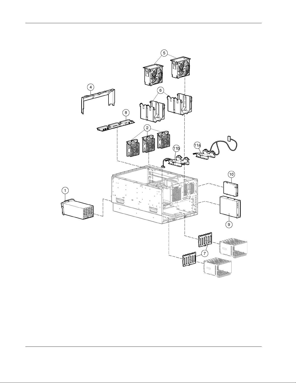
System Components Exploded View
Figure 1-2: Exploded view of the server system components
1-4 HP ProLiant ML530 Generation 2 Server Maintenance and Service Guide
HP CONFIDENTIAL Codename: Mount Olympus Part Number: 281405-004 Last Saved On: 7/31/03 1:32 PM

System Components Spare Parts List
Table 1-2: System Components Spare Parts List
Item Description Spare Part Number
1 Power supply, hot-plug, 600 W 231782-001
2 Redundant drive fans, hot-plug, 92 mm 161657-001
3 Drive fan power cable bracket* 249147-001
4 Drive air baffle 178195-001
5 CPU and I/O fans, hot-plug 5 inch 122225-001
6 Fan basket 161658-001
Backplanes
7 SCSI backplane 263035-001
8 Power backplane 233962-001
Mass Storage Devices
9 CD-ROM drive 233408-001
10 Diskette drive 233409-001
11
a) CPU fan basket adapter 158462-002
b) I/O fan basket adapter 158462-001
Fan bracket kit
Illustrated Parts Catalog
159321-001
*Not shown
HP ProLiant ML530 Generation 2 Server Maintenance and Service Guide 1-5
HP CONFIDENTIAL Codename: Mount Olympus Part Number: 281405-004 Last Saved On: 7/31/03 1:32 PM

Illustrated Parts Catalog
System Tray Components Exploded View
Figure 1-3: Exploded view of the server system tray components
1-6 HP ProLiant ML530 Generation 2 Server Maintenance and Service Guide
HP CONFIDENTIAL Codename: Mount Olympus Part Number: 281405-004 Last Saved On: 7/31/03 1:32 PM

System Tray Components Spare Parts List
Table 1-3: System Tray Components Spare Parts List
Item Description Spare Part Number
Illustrated Parts Catalog
10
11
System Components
1 Processor power module (PPM) 231783-001
2 Processor with Heatsink
Intel Xeon 2.4-GHz processor/heatsink assembly
Intel Xeon 2.8-GHz processor/heatsink assembly* 307547-001
Boards
3 Memory board 233960-001
4 PCI backplane 233961-001
5
System board kit
a) System board
b) System tray
c) Processor retaining bracket
Memory (DIMMs)
6 256-MB PC1600, DDR, ECC, SDRAM DIMM 249674-001
7 512-MB PC1600, DDR, ECC, SDRAM DIMM* 249675-001
8 1-GB PC1600, DDR, ECC, SDRAM DIMM* 249676-001
9 2-GB PC1600, DDR, ECC, SDRAM DIMM* 265791-001
Latch kit*
a) Expansion slot latch and base, blue
b) Expansion slot latch and base, carbon
c) PCI retaining clip, blue
d) PCI retaining clip, carbon
e) Memory board guide
f) Front bezel retainer
Power Cable Kit*
a) Drive fan cable 158465-001
b) CD-ROM/diskette drive cable 158469-001
c) SCSI drive cable 158470-001
d) LVD cable 158471-001
249144-001
233959-001
249746-001
159319-001
*Not shown
HP ProLiant ML530 Generation 2 Server Maintenance and Service Guide 1-7
HP CONFIDENTIAL Codename: Mount Olympus Part Number: 281405-004 Last Saved On: 7/31/03 1:32 PM
continued

Illustrated Parts Catalog
Table 1-3: System Tray Components Spare Parts List continued
Item Description Spare Part Number
12
PCI-X Hot-plug basket and processor baffle
307383-001
a) Processor air baffle
b) Hot-plug expansion board basket
13
Signal Cable Kit*
180305-001
a) CD-ROM data cable 158473-002
b) 34-Pin data cable 158472-002
c) Diskette drive data cables 158474-001
d) SCSI data cable, 2 drop 157855-001
14
ML530 Cable Kit*
249146-001
a) SCSI data cable, blue 166298-024
b) SCSI data cable, yellow 166298-025
c) Internal-to-external SCSI cable, 12 inch 232112-001
d) PCI to system board data cable 232111-001
e) Power backplane cable 232109-001
f) Front panel LED assembly with cable 225034-002
g) Backplane to system board cable 232110-001
Miscellaneous
15 3-V lithium replacement battery* 175115-001
16 Enhanced keyboard, US* 244000-001
17 Two-button mouse* 113907-001
18 Torx T-15 tool* 199630-001
19 Rack-mounting hardware kit* 277921-001
20 Third-party rack-mounting hardware kit* 277922-001
21 Country kit, rack and tower* 249148-001
22 Return kit, rack (shipping box)* 174795-001
23 Return kit, tower (shipping box)* 265792-001
24 Maintenance and service guide* 265793-001
Options
25 18.2-GB hot-plug Wide-Ultra3 SCSI hard drive with tray
152190-001
(10,000 rpm, 1 inch)*
26 36.4-GB hot-plug Wide-Ultra3 hard drive (15,000 rpm, 1 inch)* 233350-001
27 18.2-GB hot-plug Wide-Ultra3 hard drive (15,000 rpm, 1 inch)* 189395-001
28 36.4-GB hot-plug Wide-Ultra3 hard drive (10,000 rpm, 1 inch)* 177986-001
29 72.8-GB hot-plug Wide-Ultra3 hard drive (10,000 rpm, 1 inch)* 233349-001
30 DVD drive* 217801-001
*Not shown
continued
1-8 HP ProLiant ML530 Generation 2 Server Maintenance and Service Guide
HP CONFIDENTIAL Codename: Mount Olympus Part Number: 281405-004 Last Saved On: 7/31/03 1:32 PM

Illustrated Parts Catalog
Table 1-3: System Tray Components Spare Parts List continued
Item Description Spare Part Number
31 Backplane, internal two-bay hot-plug SCSI drive cage* 253761-001
32 Fan kit, internal two-bay hot-plug SCSI drive cage* 253762-001
*Not shown
HP ProLiant ML530 Generation 2 Server Maintenance and Service Guide 1-9
HP CONFIDENTIAL Codename: Mount Olympus Part Number: 281405-004 Last Saved On: 7/31/03 1:32 PM

Removal and Replacement Procedures
This chapter provides subassembly/module-level removal and replacement procedures for
ProLiant ML530 Generation 2 servers. After completing all necessary removal and
replacement procedures, run the Diagnostics program to be sure that all components operate
properly.
You need the following items for some procedures:
•
Torx T-15 tool
•
Torx T-10 tool
•
Diagnostics Utility from the HP SmartStart for Servers CD
Safety Considerations
Before performing service procedures, review the following safety information.
2
Electrostatic Discharge
A discharge of static electricity can damage static-sensitive devices or microcircuitry. Proper
packaging and grounding techniques are necessary precautions to prevent damage. To
prevent electrostatic damage:
•
Transport products in static-safe containers such as conductive tubes, bags, or boxes.
•
Keep electrostatic-sensitive parts in their containers until they arrive at static-free
stations.
•
Cover workstations with approved static-dissipating material. Use a wrist strap connected
to the work surface and properly grounded (earthed) tools and equipment.
•
Keep work area free of nonconductive materials such as ordinary plastic assembly aids
and foam packing.
•
Be sure that you are properly grounded (earthed) when touching a static-sensitive
component or assembly.
•
Avoid touching pins, leads, or circuitry.
•
Use nonconductive field service tools.
HP ProLiant ML530 Generation 2 Server Maintenance and Service Guide 2-1
HP CONFIDENTIAL Codename: Mount Olympus Part Number: 281405-004 Last Saved On: 7/31/03 1:39 PM
Removal and Replacement Procedures
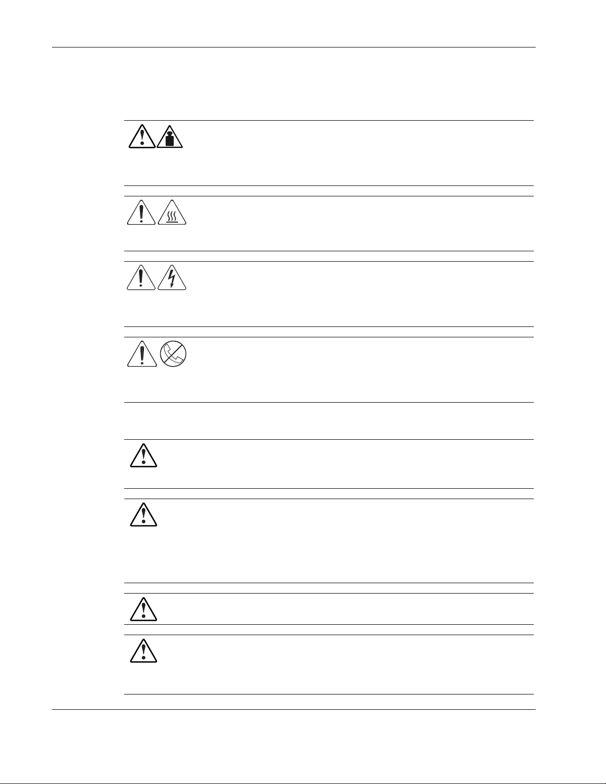
Symbols on Equipment
These symbols may be located on equipment in areas where hazardous conditions may exist.
Any product or assembly marked with these symbols indicates that the
component exceeds the recommended weight for one individual to handle safely.
66 kg
146 lb
WARNING: To reduce the risk of personal injury or damage to the equipment,
observe local occupational health and safety requirements and guidelines for
manual material handling.
Any surface or area of the equipment marked with these symbols indicates the
presence of a hot surface or a hot component.
WARNING: To reduce the risk of injury from a hot component, allow the surface
to cool before touching it.
Any surface or area of the equipment marked with these symbols indicates the
presence of electrical shock hazards. The enclosed area contains no operator
serviceable parts.
WARNING: To reduce the risk of injury from electrical shock hazards, do not
open this enclosure.
Any RJ-45 receptacle marked with these symbols indicates a network interface
connection.
WARNING: To reduce the risk of electrical shock, fire, or damage to the
equipment, do not plug telephone or telecommunications connectors into this
receptacle.
Rack Warnings and Cautions
WARNING: To reduce the risk of personal injury or damage to the equipment,
adequately stabilize the rack before extending a component outside the rack. Extend
only one component at a time. A rack may become unstable if more than one
component is extended.
WARNING: To reduce the risk of personal injury or damage to the equipment:
• Extend the leveling jacks to the floor.
• Rest the full weight of the rack on the leveling jacks.
• Attach the stabilizers to the rack if it is a single rack installation.
• Couple the racks together in multiple rack installations.
WARNING: When installing the server in a telco rack, adequately secure the rack frame
to the building structure at the top and bottom.
WARNING: To reduce the risk of personal injury or damage to the equipment, use two
or more people to safely unload the rack from the pallet. An empty 42U rack weighs
115 kg (253 lb), is over 2.1 m (7 ft) tall, and may become unstable when moved on its
casters. Handle the rack from both sides as it rolls down the ramp from the pallet. Do
not stand in front of the rack.
2-2 HP ProLiant ML530 Generation 2 Server Maintenance and Service Guide
HP CONFIDENTIAL Codename: Mount Olympus Part Number: 281405-004 Last Saved On: 7/31/03 1:39 PM
CAUTION: Always begin by mounting the heaviest item on the bottom of the rack. Continue
to populate the rack from the bottom to the top.
Server Warnings and Cautions
WARNING: Do not exceed the level of repair specified in the procedures in the product
documentation. All troubleshooting and repair procedures are detailed to allow only
subassembly or module-level repair. Because of the complexity of the individual
boards and subassemblies, do not attempt to make repairs at the component level or to
make modifications to any printed wiring board. Improper repairs can create a safety
hazard.
WARNING: To reduce the risk of personal injury from hot surfaces, allow the hot-plug
drives and the internal system components to cool before touching.
WARNING: To reduce the risk of electrical shock or damage to the equipment:
• Do not disable the AC power cord grounding plug. The grounding plug is an
important safety feature.
• Plug the power cord into a grounded (earthed) electrical outlet that is easily
accessible at all times.
• Unplug the power cord from each power supply to disconnect power to the
equipment.
WARNING: Before lifting the server remove all hot-plug power supplies and hard
drives to reduce weight.
WARNING: The installation of internal options and routine maintenance and service of
this product should be performed by individuals who are knowledgeable about the
procedures, precautions, and hazards associated with equipment containing
hazardous energy levels.
WARNING: Do not use conductive tools that could bridge live parts. Remove all
watches, rings, or loose jewelry when working in hot-plug areas of an energized server.
WARNING: Do not replace non-hot-plug components while power is applied to the
product. First, shut down the product and disconnect all AC power cords.
WARNING: Be sure that the AC power supply branch circuit that provides power to the
rack is not overloaded. Maintaining a low electric current draw reduces the risk of
personal injury, fire, or damage to the equipment. The total rack load should not
exceed 80 percent of the branch circuit rating. Consult the electrical authority having
jurisdiction over your facility for wiring and installation requirements.
CAUTION: Protect the server from power fluctuations and temporary interruptions with a
regulating uninterruptible power supply (UPS). This device protects the hardware from
damage caused by power surges and voltage spikes and keeps the system in operation
during a power failure.
Removal and Replacement Procedures
HP ProLiant ML530 Generation 2 Server Maintenance and Service Guide 2-3
HP CONFIDENTIAL Codename: Mount Olympus Part Number: 281405-004 Last Saved On: 7/31/03 1:39 PM

Removal and Replacement Procedures
CAUTION: Do not operate the server for extended periods without the access panel.
Operating the server without the access panel results in improper airflow and improper cooling
that can lead to thermal damage.
CAUTION: Reinstall each hard drive into the specific slot from which it was removed. Mixing
the hard drives adversely affects your system drive configuration.
Accessing Server Components
In order to access components in your ProLiant ML530 Generation 2 server, you may be
required to perform any or all of the following procedures:
•
Extending the server from the rack
•
Opening the hot-plug door
•
Removing the front bezel door (tower model only)
•
Removing the rack bezel (rack model only)
•
Removing the access panel
•
Opening the system tray
All of these procedures can be performed without powering down the server or causing
system shutdown.
2-4 HP ProLiant ML530 Generation 2 Server Maintenance and Service Guide
HP CONFIDENTIAL Codename: Mount Olympus Part Number: 281405-004 Last Saved On: 7/31/03 1:39 PM

Extending the Server from the Rack
To extend the server from the rack:
1. Loosen the front panel thumbscrews that secure the server to the front of the rack (1).
WARNING: To reduce the risk of personal injury, be careful when pressing the
server rail-release latches and sliding the component into or out of the rack. The
sliding rails could pinch your fingertips.
2. Extend the server until the server rail-release latches engage (2).
Removal and Replacement Procedures
Figure 2-1: Extending the server from the rack
To slide the server back into the rack after performing the maintenance procedure:
1. Press the server rail-release latches.
2. Slide the server fully into the rack.
3. Secure the server by tightening the thumbscrews.
HP ProLiant ML530 Generation 2 Server Maintenance and Service Guide 2-5
HP CONFIDENTIAL Codename: Mount Olympus Part Number: 281405-004 Last Saved On: 7/31/03 1:39 PM
Removal and Replacement Procedures
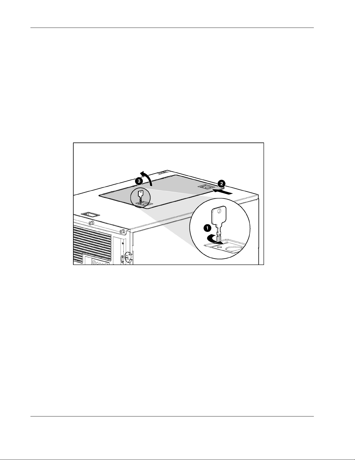
Opening the Hot-Plug Door
To open the hot-plug door:
1. Extend the server from the rack. Refer to the “Extending the Server from the Rack”
section in this chapter.
2. Unlock both locks on the hot plug door (1).
IMPORTANT: The key to the hot-plug door ships attached to the front bezel door on tower model
servers, and attached to the system tray handle on rack model servers.
3. Slide the hot-plug door latches open (2).
4. Open the hot-plug door (3).
Figure 2-2: Opening the hot-plug door
Reverse steps 1 through 4 to close the hot-plug door.
2-6 HP ProLiant ML530 Generation 2 Server Maintenance and Service Guide
HP CONFIDENTIAL Codename: Mount Olympus Part Number: 281405-004 Last Saved On: 7/31/03 1:39 PM
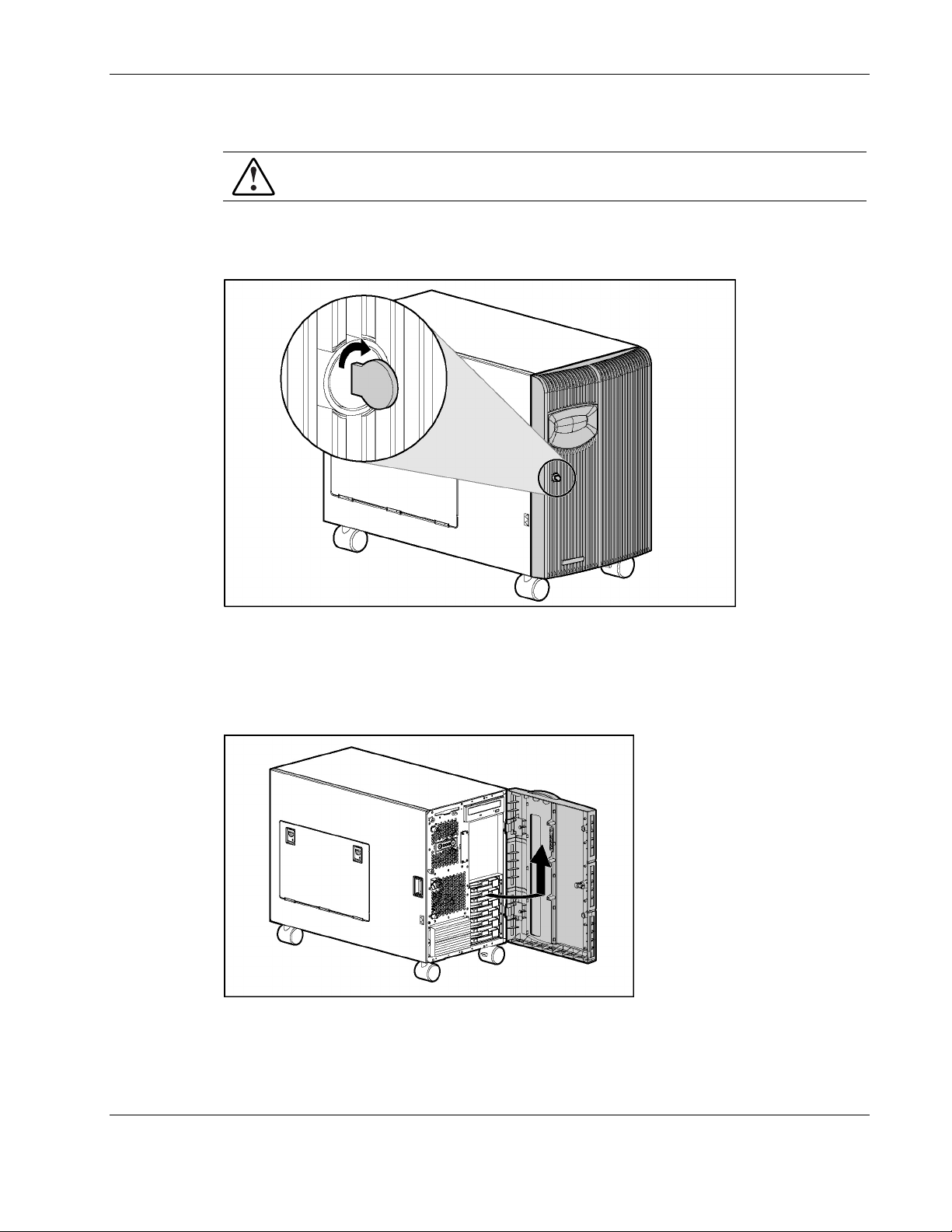
Removing the Front Bezel Door (Tower Model Only)
WARNING: To reduce the risk of personal injury from hot surfaces, allow the internal
system components to cool before handling the components.
To remove the front bezel door:
1. Unlock the front bezel door.
Removal and Replacement Procedures
Figure 2-3: Unlocking the front bezel door
2. Swing open the front bezel door fully.
3. Lift the front bezel door.
4. Pull the door away from the chassis hinges.
Figure 2-4: Removing the front bezel door (tower model only)
Reverse steps 1 through 4 to replace the front bezel door.
HP ProLiant ML530 Generation 2 Server Maintenance and Service Guide 2-7
HP CONFIDENTIAL Codename: Mount Olympus Part Number: 281405-004 Last Saved On: 7/31/03 1:39 PM
Removal and Replacement Procedures
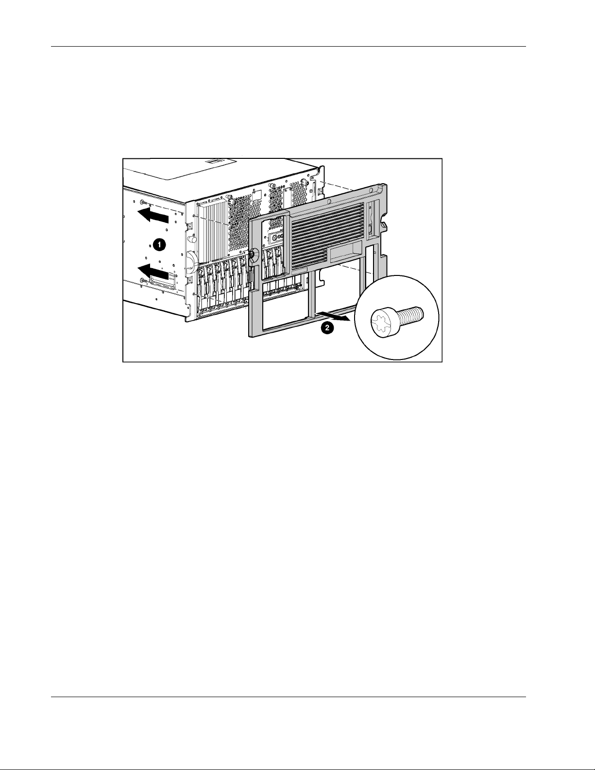
Removing the Rack Bezel (Rack Model Only)
To remove the rack bezel:
1. Remove the four Torx T-15 screws securing the rack bezel to the chassis (1).
2. Pull the rack bezel away from the chassis (2).
Figure 2-5: Removing the rack bezel (rack model only)
Reverse steps 1 and 2 to replace the rack bezel.
2-8 HP ProLiant ML530 Generation 2 Server Maintenance and Service Guide
HP CONFIDENTIAL Codename: Mount Olympus Part Number: 281405-004 Last Saved On: 7/31/03 1:39 PM
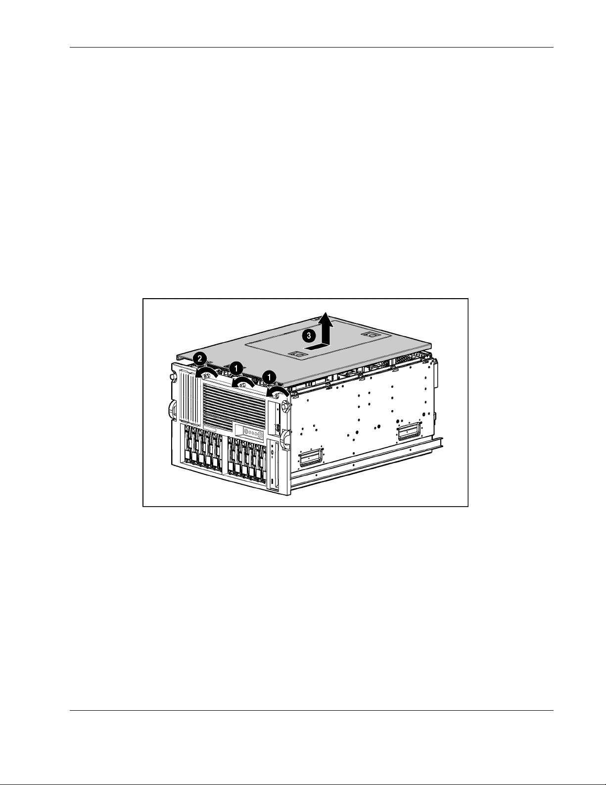
Removing the Access Panel
NOTE: For ease of service, lock the casters and lay the tower model server on its side with the access
panel up.
To remove the access panel:
1. Open the front bezel door (tower model only) and lay the server on its side with the
access panel facing upward. Refer to the “Removing the Front Bezel Door (Tower Model
Only)” section in this chapter.
2. Extend the server from the rack (rack model only). Refer to the “Extending the Server
from the Rack” section in this chapter.
3. Loosen the thumbscrews on the front of the chassis (1).
4. Use the Torx T-15 tool that ships with the server to loosen the retaining screw located on
the front of the chassis next to the two thumbscrews (2).
5. Slide the access panel toward the back of the server, and lift it away from the chassis (3).
Removal and Replacement Procedures
Figure 2-6: Removing the access panel
Reverse steps 1 through 5 to replace the access panel.
HP ProLiant ML530 Generation 2 Server Maintenance and Service Guide 2-9
HP CONFIDENTIAL Codename: Mount Olympus Part Number: 281405-004 Last Saved On: 7/31/03 1:39 PM
Removal and Replacement Procedures
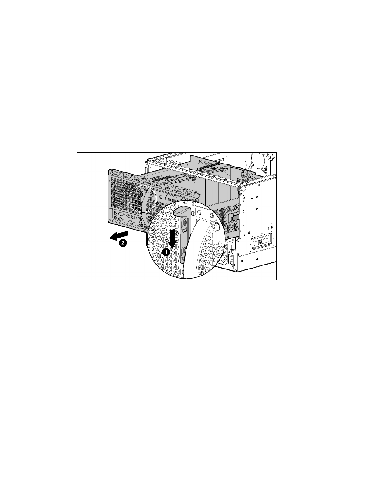
Opening the System Tray
To open the system tray:
1. Remove the access panel. Refer to the “Removing the Access Panel” section in this
chapter.
2. Press the latch adjacent to the system tray release handle to release the system tray (1).
3. Grasp the system tray release handle and pull the tray from the chassis until it stops in the
extended position (2).
NOTE: If the server is mounted into a rack, you can reach the system tray latches more easily by
extending the server from the rack (approximately the depth of the drives) before sliding the system
tray from the back of the chassis.
Figure 2-7: Opening the system tray
Hot-Plug Procedures
You can perform removal/replacement procedures for some server components without
powering down the server. The following removal/replacement procedures are hot-plug
capable:
•
Hot-plug power supplies
•
Hot-plug fans (CPU and I/O)
•
Hot-plug fans (drive)
•
Hot-plug SCSI hard drives
•
PCI and PCI-X Hot Plug expansion boards (in hot-plug slots)
2-10 HP ProLiant ML530 Generation 2 Server Maintenance and Service Guide
HP CONFIDENTIAL Codename: Mount Olympus Part Number: 281405-004 Last Saved On: 7/31/03 1:39 PM

Hot-Plug Power Supplies
CAUTION: Do not hot-remove a power supply without a redundant power supply in place.
CAUTION: Hot-plug power supplies for the ProLiant ML530 Generation 2 server are keyed to
be sure that only 600-W hot-plug power supplies can be installed in the server. The handles
on 600-W power supplies are black to distinguish them from other power supplies.
To remove a hot-plug power supply:
1. Release the AC power cord from the tie wrap on the power supply.
2. Unplug the AC power cord from the power supply.
3. Remove the retaining screw.
Removal and Replacement Procedures
Figure 2-8: Removing the retaining screw
HP ProLiant ML530 Generation 2 Server Maintenance and Service Guide 2-11
HP CONFIDENTIAL Codename: Mount Olympus Part Number: 281405-004 Last Saved On: 7/31/03 1:39 PM

Removal and Replacement Procedures
4. Press the latch in the middle of the power supply handle to release the handle (1).
5. Pull the handle downward until the unit releases from the server (2).
6. Slide the hot-plug power supply from the chassis (3).
Figure 2-9: Removing a hot-plug power supply
CAUTION: A power supply or power supply blank must always be installed in each power
supply bay for proper system cooling. If a power supply bay is left open, thermal damage may
occur.
Reverse steps 1 through 6 to replace a hot-plug power supply.
For information on power supply diagnosis, refer to the “Hot-Plug Power Supply LEDs”
section in Chapter 4, “Connectors, LEDs, and Switches.”
Hot-Plug CPU and I/O Fans
The HP ProLiant ML530 Generation 2 server hot-plug fans are housed in two fan baskets.
Each basket holds a primary and a redundant hot-plug fan. The I/O fans cool the system
board components, and the CPU fans cool the processors.
CAUTION: Never remove both hot-plug fans from either fan basket while the server is
powered up. Overheating and damage to hardware could result. If the appropriate HP
software drivers are installed, the operating system software initiates a power shutdown in
case of overheating.
2-12 HP ProLiant ML530 Generation 2 Server Maintenance and Service Guide
HP CONFIDENTIAL Codename: Mount Olympus Part Number: 281405-004 Last Saved On: 7/31/03 1:39 PM

Removal and Replacement Procedures
To remove a hot-plug CPU or I/O fan:
1. Remove the front bezel door (tower model only), and lay the server on its side with the
access panel facing upward. Refer to the “Removing the Front Bezel Door (Tower Model
Only)” section in this chapter.
2. Extend the server from the rack (rack model only). Refer to the “Extending the Server
from the Rack” section in this chapter.
3. Remove the access panel. Refer to the “Removing the Access Panel” section in this
chapter.
4. Press and hold the locking latch (1).
5. Lift the hot-plug CPU or I/O fan out of the fan basket (2).
Figure 2-10: Removing a hot-plug CPU or I/O fan
Reverse steps 1 through 5 to replace a hot-plug CPU fan or hot-plug I/O fan.
For information on hot-plug fan diagnosis, refer to the “Hot-Plug Fan LEDs” section in
Chapter 4, “Connectors, LEDs, and Switches.”
HP ProLiant ML530 Generation 2 Server Maintenance and Service Guide 2-13
HP CONFIDENTIAL Codename: Mount Olympus Part Number: 281405-004 Last Saved On: 7/31/03 1:39 PM
 Loading...