

Page 1

HP ProLiant ML310 Server
Setup and Installation Guide
January 2003 (Second Edition)
Part Number 274431-002
Page 2

© 2002, 2003 Hewlett-Packard Development Company, L.P.
Microsoft and Windows are trademarks of Microsoft Corporati on in the U.S. and other
countries.
Intel, and Pentium are trademarks of Intel Corporation in the U. S. and other countries.
Hewlett-Packard Company shall not be liable for technical or editorial errors or omissions
contained herein. The information in t his document is provided “as is” without warranty of
any kind and is subject to change without notice. The warranties for HP products are set forth
in the express limited war r anty statements accompanying such products. Nothing herein
should be construed as constituting an additional warranty.
HP ProLiant ML310 Se r ver Setup and Install ation Guide
January 2003 (Sec ond Edition)
Part Number 274431-002
Page 3

Contents
About This Guide
Audience Assumptions...................................................................................................... xi
Important Safety Information............................................................................................ xi
Symbols on Equipment ..................................................................................................... xi
Rack Stability..................................................................................................................xiii
Symbols in Text............................................................................................................... xiii
Related Documents.......................................................................................................... xiv
Getting Help....................................................................................................................xiv
Technical Support..................................................................................................... xiv
HP Website.................................................................................................................xv
Authorized Reseller....................................................................................................xv
Reader’s Comments ..........................................................................................................xv
Chapter 1
Server Features
Standard Hardware Features............................................................................................1-3
Drive Bay Configuration...........................................................................................1-3
Front Panel Components........................................................................................... 1-5
Rear Panel Connectors.............................................................................................. 1-6
Network Interface Controller Connector LEDs........................................................ 1-7
System Board Components....................................................................................... 1-8
Processor and Server Me mory................................................................................ 1-12
Expansion Slots.......................................................................................................1-12
Storage Controller................................................................................................... 1-12
Network Controller................................................................................................. 1-12
Video Controller.....................................................................................................1-13
Ports/Connectors..................................................................................................... 1-13
HP ProLiant ML310 Server Setup and Installation Guide iii
Page 4

Contents
Power Supply ..........................................................................................................1-14
Warranty........................................................................................................................1-14
Server Configuration and Management.........................................................................1-15
Security..........................................................................................................................1-16
Chapter 2
Overview of Server Installation
Selecting a Site.................................................................................................................2-2
Installing the Rack Server................................................................................................2-3
Rack-Enabling Option...............................................................................................2-3
Rack Environment.....................................................................................................2-4
Locating Materials...........................................................................................................2-5
Installation Sequence.......................................................................................................2-6
Factory-Installed Operating Systems ........................................................................2-6
Operating Systems Purchased Separately .................................................................2-9
Configuring the Server...................................................................................................2-11
Server Registration........................................................................................................2-11
Chapter 3
Hardware Options Installation
Preparing the Server.........................................................................................................3-2
Powering Down the Server........................................................................................3-2
Removing the Front Bezel.........................................................................................3-3
Removing the Access Panel......................................................................................3-4
Removing Bezel Blanks............................................................................................3-5
Removing a Drive Tray.............................................................................................3-6
Storage Devices...............................................................................................................3-7
Removing a Hard Drive From a Hard Drive Bay......................................................3-8
Installing a Hard Drive Into a Hard Drive Bay .......................................................3-11
Installing a Hard Drive into a Removable Media Bay............................................3-14
Removing a Hard Drive or Other Device from a Removable Media Bay ..............3-16
Installing a Tape Drive or Other Removable Media Device...................................3-17
Installing the Two-Bay Hot-Plug SCSI Drive Cage Into a Removable Media Bay3-20
Installing an Expansion Board.......................................................................................3-24
Memory Modules...........................................................................................................3-27
Technical Information and Important Guidelines...................................................3-27
Removing a Memory Module .................................................................................3-28
Installing a Memory Modu le...................................................................................3-29
iv HP ProLiant ML310 Server Setup and Installation Guide
Page 5

Processor .......................................................................................................................3-31
Removing the Processor ......................................................................................... 3-31
Installing the Processor........................................................................................... 3-33
Battery...........................................................................................................................3-36
Replacing the Battery.............................................................................................. 3-37
Chapter 4
Cabling Guidelines
SCSI Cabling................................................................................................................... 4-2
Identifying SCSI Components..................................................................................4-3
Cabling SCSI Devices and Hard Drives................................................................... 4-6
Cabling a Smart Array Controller............................................................................. 4-7
Cabling a Two-Bay Hot-Plug SCSI Drive Cage.......................................................4-8
ATA Cabling.................................................................................................................4-10
Identifying ATA Components................................................................................4-11
Cabling ATA/100 RAID Devices........................................................................... 4-13
Cabling an ATAPI Tape Drive or Other ATAPI Device........................................ 4-15
Chapter 5
Server Configuration and Utilities
ROM-Based Setup Utility...............................................................................................5-2
Navigating RBSU.....................................................................................................5-2
Using RBSU ............................................................................................................. 5-3
Redundant ROM Support................................................................................................ 5-7
Safety and Security Benefits..................................................................................... 5-8
Access to Redundant ROM Settings......................................................................... 5-8
ROMPaq..........................................................................................................................5-9
SmartStart Software........................................................................................................5-9
SmartStart Diskette Builder...........................................................................................5-10
Insight Manager............................................................................................................. 5-10
Survey Utility................................................................................................................5-11
Diagnostics Utility......................................................................................................... 5-11
Automatic Server Recovery..........................................................................................5-12
Power-On Self-Test....................................................................................................... 5-12
System Firmware Update.............................................................................................. 5-12
Contents
HP ProLiant ML310 Server Setup and Installation Guide v
Page 6

Contents
Chapter 6
RAID Configuration and Management
Introduction to RAID.......................................................................................................6-1
Overview of RAID....................................................................................................6-1
RAID Terminology...................................................................................................6-2
Integrated ATA RAID Configuration Utility..................................................................6-3
Configuration Utility Features...................................................................................6-3
Using the Configuration Utility.................................................................................6-4
Integrated ATA RAID Management Utility....................................................................6-8
Management Utility Features....................................................................................6-8
Using the Management Utility..................................................................................6-8
Troubleshooting...............................................................................................................6-9
Drive Connection Tips..............................................................................................6-9
Configuration and Setup Tips..................................................................................6-10
Appendix A
Regulatory Compliance Notices
Regulatory Compliance Identification Numbers............................................................A-1
Federal Communications Commission Notice ...............................................................A-1
Class A Equipment...................................................................................................A-2
Class B Equipment...................................................................................................A-2
Declaration of Conformity for Products Marked with the FCC Logo – United States
Only..........................................................................................................................A-3
Modifications ...........................................................................................................A-3
Cables.......................................................................................................................A-3
Canadian Notice (Avis Canadien)..................................................................................A-4
Class A Equipment...................................................................................................A-4
Class B Equipment...................................................................................................A-4
European Union Notice ..................................................................................................A-4
Japanese Notice...............................................................................................................A-5
China Taiwan Notice.......................................................................................................A-5
Laser Devices..................................................................................................................A-6
Laser Safety Warnings.............................................................................................A-6
Compliance with CDRH Regulations......................................................................A-6
Compliance with International Regulations.............................................................A-6
Laser Product Label..................................................................................................A-7
Laser Information.....................................................................................................A-7
Battery Replacement Notice...........................................................................................A-8
vi HP ProLiant ML310 Server Setup and Installation Guide
Page 7

Power Cords................................................................................................................... A-8
Mouse Compliance Statement........................................................................................ A-9
Appendix B
Electrostatic Discharge
Preventing Electrostatic Discharge..................................................................................B-1
Grounding Methods.........................................................................................................B-2
Appendix C
Server Error Messages
Appendix D
Troubleshooting
When the Server Does Not Start.................................................................................... D-3
Diagnosis Steps.............................................................................................................. D-5
Problems After Initial Sta rtup........................................................................................ D-9
Other Information Resources ....................................................................................... D-12
Appendix E
LED Indicators, Switches, and Jumpers
LEDs................................................................................................................................E-2
Server LEDs..............................................................................................................E-2
System Board LEDs..................................................................................................E-4
Network Controller LEDs.........................................................................................E-7
Switch Settings................................................................................................................E-8
System Configuration Switch Settings.....................................................................E-8
System ID Switch Settings......................................................................................E-12
Jumper Settings.............................................................................................................E-13
SCSI Device Jumper Settings.................................................................................E-13
ATA Device Jumper Settings.................................................................................E-13
Contents
Appendix F
Specifications
Server Specifications.......................................................................................................F-2
Minimum Hardware Configuration.................................................................................F-3
Supported Operating Systems.........................................................................................F-4
Drivers.............................................................................................................................F-4
HP ProLiant ML310 Server Setup and Installation Guide vii
Page 8

Contents
Index
List of Figures
Figure 1-1: ProLiant ML310 server......................................................................................1-3
Figure 1-2: Drive bay configuration......................................................................................1-4
Figure 1-3: Front panel components......................................................................................1-5
Figure 1-4: Rear panel connectors.........................................................................................1-6
Figure 1-5: NIC connector ....................................................................................................1-7
Figure 1-6: SCSI system board components.........................................................................1-8
Figure 1-7: ATA system board components .......................................................................1-10
Figure 2-1: ProLiant ML310 server installed into a rack......................................................2-3
Figure 2-2: Powering up the server.......................................................................................2-8
Figure 2-3: Inserting a CD into the CD-ROM drive ...........................................................2-11
Figure 3-1: Removing the front bezel...................................................................................3-3
Figure 3-2: Removing the access panel.................................................................................3-4
Figure 3-3: Removing a bezel blank .....................................................................................3-5
Figure 3-4: Removing a drive tray........................................................................................3-6
Figure 3-5: Disconnecting the hard drive cables (SCSI model)............................................3-8
Figure 3-6: Disconnecting the hard drive cables (ATA model)............................................3-9
Figure 3-7: Removing a hard drive.....................................................................................3-10
Figure 3-8: Removing the drive compartment....................................................................3-11
Figure 3-9: Locating the hard drive screws.........................................................................3-12
Figure 3-10: Installing a 3.5-inch hard drive.......................................................................3-13
Figure 3-11: Installing a hard drive into a removable media bay drive tray .......................3-14
Figure 3-12: Installing a hard drive into a removable media bay........................................3-15
Figure 3-13: Removing a device from the removable media bay .......................................3-16
Figure 3-14: Removing the rails from the drive tray...........................................................3-18
Figure 3-15: Installing a tape drive .....................................................................................3-19
Figure 3-16: Removing the bezel from the drive cage........................................................3-20
Figure 3-17: Removing media bay blanks...........................................................................3-21
Figure 3-18: Removing the CD-ROM drive .......................................................................3-21
Figure 3-19: Moving the CD-ROM drive ...........................................................................3-22
Figure 3-20: Attaching the rails to the drive cage...............................................................3-23
Figure 3-21: Expansion slots...............................................................................................3-24
Figure 3-22: Removing the expansion slot cover................................................................3-25
Figure 3-23: Releasing the expansion board retainer..........................................................3-26
Figure 3-24: Installing an expansion board.........................................................................3-26
viii HP ProLiant ML310 Server Setup and Installation Guide
Page 9

Contents
Figure 3-25: Removing a DIMM........................................................................................ 3-28
Figure 3-26: Locating DIMM sockets ................................................................................ 3-29
Figure 3-27: Installing a DIMM......................................................................................... 3-30
Figure 3-28: Locating the processor socket........................................................................ 3-31
Figure 3-29: Removing the processor from the syste m board............................................ 3-32
Figure 3-30: Installing a processor...................................................................................... 3-33
Figure 3-31: Installing the heatsink.................................................................................... 3-34
Figure 3-32: Securing the heatsink retainer clips................................................................3-34
Figure 3-33: Plugging in the system fan............................................................................. 3-35
Figure 3-34: Removing the battery from the SCSI system board....................................... 3-38
Figure 3-35: Removing the battery from the ATA system board....................................... 3-38
Figure 4-1: SCSI cable with terminator................................................................................ 4-3
Figure 4-2: Internal SCSI components.................................................................................. 4-4
Figure 4-3: 68-to-50 pin (wide-to-narrow) SCSI adapter..................................................... 4-5
Figure 4-4: Cabling a SCSI hard drive or other device......................................................... 4-6
Figure 4-5: Removing the SCSI cab le fro m the system board.............................................. 4-7
Figure 4-6: Connecting the SCSI cable to the Smart Array Controller ................................ 4-8
Figure 4-7: Cabling a two-bay hot-plug SCSI drive cage..................................................... 4-9
Figure 4-8: ATA cable connectors......................................................................................4-11
Figure 4-9: Internal ATA components................................................................................ 4-12
Figure 4-10: ATA cabling sequence................................................................................... 4-13
Figure 4-11: Cabling an ATAPI tape drive......................................................................... 4-15
Figure E-1: Power button and server LEDs..........................................................................E-3
Figure E-2: System Board LEDs..........................................................................................E-4
Figure E-3: Network controller LEDs..................................................................................E-7
Figure E-4: System configuration switch default settings....................................................E-8
Figure E-5: System ID Switch............................................................................................E-12
List of Tables
Table 1-1: Drive Bay Dimensions........................................................................................ 1-4
Table 1-2: Front Panel Components ..................................................................................... 1-5
Table 1-3: Rear Panel Connectors........................................................................................ 1-6
Table 1-4: NIC Connector LEDs.......................................................................................... 1-7
Table 1-5: SCSI System Board Components........................................................................ 1-9
Table 1-6: ATA System Board Components...................................................................... 1-11
Table 3-1: Expansion Slots................................................................................................. 3-24
Table 3-2: DIMM Sockets.................................................................................................. 3-29
HP ProLiant ML310 Server Setup and Installation Guide ix
Page 10

Contents
Table 4-1: Internal SCSI Components ..................................................................................4-4
Table 4-2: ATA Cable Connectors......................................................................................4-11
Table 4-3: Internal ATA Components.................................................................................4-12
Table 4-4: ATA Cabling Sequence.....................................................................................4-14
Table D-1: Diagnosis Steps..................................................................................................D-5
Table D-2: Front Panel Power-On/Standby LED Is Not On................................................D-7
Table D-3: Server Does Not Have Video.............................................................................D-8
Table D-4: Problems After Initial Startup..........................................................................D-10
Table D-5: ProLiant ML310 Server Troubleshooting Resources ......................................D-12
Table E-1: Power Button and Server LEDs......................................................................... E-3
Table E-2: System Board LEDs........................................................................................... E-5
Table E-3: Network Controller LEDs.................................................................................. E-7
Table E-4: System Configuration Switch Settings............................................................... E-9
Table E-5: System ID Switch Settings............................................................................... E-12
Table F-1: ProLiant ML310 Server Specifications...............................................................F-2
Table F-2: Minimum Hardware Configuration.....................................................................F-3
x HP ProLiant ML310 Server Setup and Installation Guide
Page 11

This guide provides step-by-step instructions for installation, and reference
information for operation, troublesho ot ing, and futu re upgrad es for the HP ProLia nt
ML310 server.
Audience Assumptions
This guide is for the person who installs, administers, and troubleshoots servers. HP
assumes you are qualified in the servicing of computer equipment and trained in
recognizing hazards in products with hazardous energy levels.
About This Guide
Important Safety Information
Before installing this product, read the Important Safety Information documen t
included with the server.
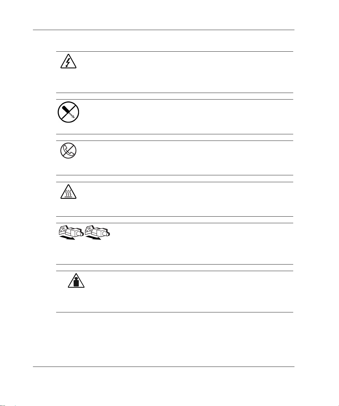
Symbols on Equipment
The following symbols may be placed on equipment to indicate the presence of
potentially hazardous conditions:
WARNING: This symbol, in conjunction with any of the following symbols,
indicates the presence of a potential hazard. The potential for injury exists if
warnings are not observed. Consult your documentation for specific details.
HP ProLiant ML310 Server Setup and Installation Guide xi
Page 12
About This Guide
Weight in kg
Weight in lb
This symbol indicates the presence of hazardous energy circuits or electric
shock hazards. Refer all servicing to qualified personnel.
WARNING: To reduce the risk of injury from electric shock hazards, do not
open this enclosure. Refer all maintenance, upgrades, and servicing to
qualified personnel.
This symbol indicates the presence of electric shock hazards. The area
contains no user or field serviceable parts. Do not open for any reason.
WARNING: To reduce the risk of injury from electric shock hazards, do not
open this enclosure
This symbol on an RJ-45 receptacle indicates a network interface connection.
WARNING: To reduce the risk of electric shock, fire, or damage to the
equipment, do not plug telephone or telecommunications connectors into this
receptacle.
This symbol indicates the presence of a hot surface or hot component. If this
surface is contacted, the potential for injury exists.
WARNING: To reduce the risk of injury from a hot component, allow the
surface to cool before touching.
These symbols, on power supplies or systems, indicate that the
equipment is supplied by multiple sources of power.
WARNING: To reduce the risk of injury from electric shock,
remove all power cords to completely disconnect power from the
system.
This symbol indicates that the component exceeds the recommended
weight for one individual to handle safely.
WARNING: To reduce the risk of personal injury or damage to the
equipment, observe local occupational health and safety requirements
and guidelines for manual material handling.
xii HP ProLiant ML310 Server Setup and Installation Guide
Page 13

Rack Stability
WARNING: To reduce the risk of personal injury or damage to the equipment,
be sure that:
· The leveling jacks are extended to the floor.
· The full weight of the rack rests on the leveling jacks.
· The stabilizing feet are attached to the rack if it is a single-rack installation.
· The racks are coupled together in multiple-rack installations.
· Only one component is extended at a time. A rack may become unstable if
more than one component is extended for any reason.
Symbols in Text
These symbols may be found in the text of this guide. They have the following
meanings.
WARNING: Text set off in this manner indicates that failure to follow directions
in the warning could result in bodily harm or loss of life.
About This Guide
CAUTION: Text set off in this manner indicates that failure to follow directions could
result in damage to equipment or loss of information.
IMPORTANT: Text set off in this manner presents essential information to explain a concept
or complete a task.
NOTE: Text set off in this manner presents additional information to emphasize or supplement
important points of the main text.
HP ProLiant ML310 Server Setup and Installation Guide xiii
Page 14

About This Guide
Related Documents
For additional information on the topics covered in this guide, refer to the following
documentation:
· HP ProLiant ML310 Server Maintenance and Service Guide
· HP ProLiant ML310 Server Cabling Matrix:
www.compaq.com/products/servers/proliantml310/index.html
· HP ProLiant ML310 Server Quick Start poster
· Servers Troubleshooting Guide:
www3.compaq.com/support/home/index.asp (Reference Library)
Getting Help
If you have a problem and have exhausted the information in this guide, you can get
further information and other help in the following locations.
Technical Support
In North America, call the HP Technical Support Phone Center at 1-800-652-6672.
This service is available 24 hours a day, 7 days a week. For continuous quality
improvement, calls may be recorded or monitored. Outside North America, call the
nearest HP Technical Support Phone Center. Telephone numbers for worldwide
Technical Support Centers are listed on the HP website,
Be sure to have the following information available before you call HP:
· Technical support registration number (if applicable)
· Product serial number
· Product model name and number
· Applicable error messages
· Add-on boards or hardware
xiv HP ProLiant ML310 Server Setup and Installation Guide
www.hp.com.
Page 15

· Third-party hardware or software
· Operating system type and revision level
HP Website
The HP website has information on this product as well as the latest drivers and flash
ROM images. You can access the HP website at
Authorized Reseller
For the name of your nearest authorized reseller:
· In the United States, call 1-800-345-1518.
· In Canada, call 1-800-263-5868.
· Elsewhere, see the HP website for locations and telephone numbers.
Reader’s Comments
About This Guide
www.hp.com.
HP welcomes your comments on this guide. Please send your comments and
suggestions by e-mail to
ServerDocumentation@hp.com.
HP ProLiant ML310 Server Setup and Installation Guide xv
Page 16

1
Server Features
The HP ProLiant ML310 server provides the performance, reliability, and ease of
ownership you need to allow your business to grow. With support for one Intel
Pentium 4 processor (512 K Advanced Transfer Cache), up to four GB of DDR
SDRAM, and four 64-bit PCI slots, the ProLiant ML310 delivers the performance of
Pentium 4 in a true server. With the extensive testing that only HP conducts on its
servers and with features like Integrated ATA RAID and a Pre-Failure Warranty on
processors, memory, and hard drives, the ProLiant ML310 is the server your business
can depend on. And thanks to tools like SmartStart software and the Insight Manager
management tool, the server is easy to set up and easy to maintain.
Enjoy your new ProLiant server!
HP ProLiant ML310 Server Setup and Installation Guide 1-1
Page 17

Server Features
Server features include the following:
Intel Pentium 4 processor ·
·
ECC Registered PC2100 DDR SDRAM DIMM, upgradable to 4 GB
·
Capacity for:
— Five 36.4-GB non-hot-plug SCSI hard drives for a maximum of 182 GB of
— Four 80-GB ATA hard drives for a maximum of 320 GB of internal storage
— Three 36.4-GB non-hot-plug SCSI hard drives and two 72.8-GB hot-plug
·
Four removable media bays (three available)
·
IDE CD-ROM drive
·
3.5-inch diskette drive
·
Four 33-MHz 64-bit PCI slots
·
Integrated single-channel Wide Ultra3 SCSI controller or an integrated
dual-channel ATA/100 RAID controller
internal storage
hard drives in the internal two-bay hot-plug SCSI drive cage option for a
maximum of 254 GB of internal storage
·
NC7760 Gigabit Server network interface controller (NIC)
·
Integrated ATI Rage XL video controller
·
CE Mark-compliant PFC 300W power supply
·
Support for HP, Compaq branded, and most third-party racks, with the optional
rack-enabling kit
·
Support for telco racks, with the optional rack-enabling kit and optional telco rail
kit
1-2 HP ProLiant ML310 Server Setup and Installation Guide
Page 18

Figure 1-1: ProLiant ML310 server
Standard Hardware Features
The following hardware features are standard on the server, unless otherwise noted.
Server Features
Drive Bay Configuration
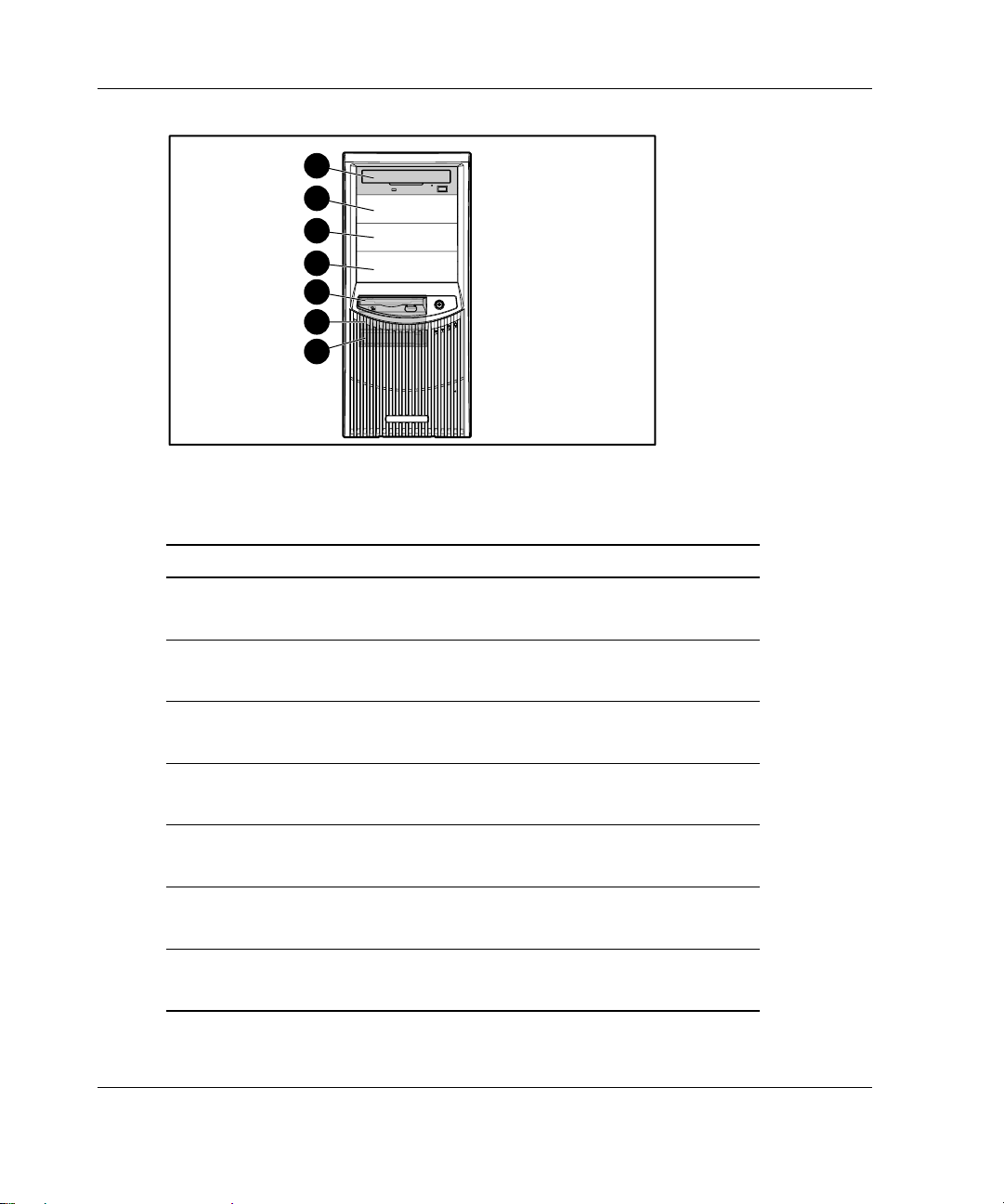
The ProLiant ML310 server supports up to seven internal drive bays. Figure 1-2 and
Table 1-1 show the drive bay configuration.
HP ProLiant ML310 Server Setup and Installation Guide 1-3
Page 19
Server Features
Figure 1-2: Drive bay configuration
Table 1-1: Drive Bay Dimensions
Item Component Location Dimension
1 IDE CD-ROM drive Media bay 1 13.34 x 4.06 cm
2 Available removable
3 Available removable
4 Available removable
5 Diskette drive Hard drive bay 1 8.9 x 2.54 cm
6 Hard drive bay Hard drive bay 2 8.9 x 2.54 cm
7 Hard drive bay Hard drive bay 3 8.9 x 2.54 cm
1
2
3
4
5
6
7
media bay
media bay
media bay
5.25 x 1.60 in
Media bay 2 13.34 x 4.06 cm
5.25 x 1.60 in
Media bay 3 13.34 x 4.06 cm
5.25 x 1.60 in
Media bay 4 13.34 x 4.06 cm
5.25 x 1.60 in
3.5 x 1.0 in
3.5 x 1.0 in
3.5 x 1.0 in
1-4 HP ProLiant ML310 Server Setup and Installation Guide
Page 20
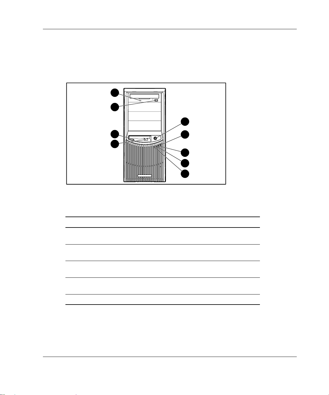
Front Panel Components
Figure 1-3 and Table 1-2 show the front panel components, including buttons and
LEDs.
9
8
Server Features
1
7
6
2
3
4
5
Figure 1-3: Front panel components
Table 1-2: Front Panel Components
Item Component Item Component
1 Power button 6 Diskette drive eject
button
2 Power LED 7 Diskette drive activity
LED
3 Hard drive activity LED 8 CD-ROM drive eject
button
4 NIC link/activity LED 9 CD-ROM drive activity
LED
5 Internal health LED
HP ProLiant ML310 Server Setup and Installation Guide 1-5
Page 21

Server Features
Rear Panel Connectors
Figure 1-4 and Table 1-3 show the rear panel connectors.
1
2
3
4
5
6
7
9
8
Figure 1-4: Rear panel connectors
Table 1-3: Rear Panel Connectors
Item Connector Item Connector
1 Power cord 6 Video
2 Mouse 7 USB ports (2)
3 Keyboard 8 RJ-45 Ethernet
4 Serial port
connector B
5 Serial port
connector A
9 Parallel port
1-6 HP ProLiant ML310 Server Setup and Installation Guide
Page 22

Network Interface Controller Connector LEDs
Figure 1-5 and Table 1-4 show the network interface controller (NIC)
connector LEDs.
1
2
Figure 1-5: NIC connector
Server Features
Table 1-4: NIC Connector LEDs
Item LED
1 Network activity
2 Network link
HP ProLiant ML310 Server Setup and Installation Guide 1-7
Page 23

Server Features
System Board Components
SCSI System Board
Figure 1-6 and Table 1-5 show the components and connectors of the SCSI system
board.
19
20
21
22
23
24
25
26
18
17
16
15
14
13
12
1
9 8
1011
Figure 1-6: SCSI system board components
2
3
4
5
6
7
1-8 HP ProLiant ML310 Server Setup and Installation Guide
Page 24

Table 1-5: SCSI System Board Components
Item Component Item Component
1 Power supply connectors 14 64-bit PCI expansion slot 1
2 Power switch assembly connector 15 NMI switch
3 Diskette drive connector 16 System fan connector
4 IDE connector (ATAPI devices) 17 CPU fan connector
5 DIMM slots 18 Processor socket
6 CR2032 battery 19 Keyboard connector
7 SCSI connector 20 Mouse connector
8 System configuration switch 21 Parallel port connector
9 RIB 30-pin header 22 Serial port connector B
10 System ID switch 23 Serial port connector A
11 64-bit PCI expansion slot 4 24 Video connector
12 64-bit PCI expansion slot 3 25 RJ-45 Ethernet connector
13 64-bit PCI expansion slot 2 26 USB port connectors (2)
Server Features
Note: For information on system board LEDs and syst em configuration switch set tings, refer to
Appendix E, “LED Indicators, Switches, and Jumpers.”
HP ProLiant ML310 Server Setup and Installation Guide 1-9
Page 25

Server Features
ATA System Board
Figure 1-7 and Table 1-6 show the components and connectors of the ATA system
board.
20 21
22
23
24
25
26
27
19
18
17
16
15
14
13
1
10 9
1112
Figure 1-7: ATA system board components
2
3
4
5
6
7
8
1-10 HP ProLiant ML310 Server Setup and Installation Guide
Page 26

Table 1-6: ATA System Board Components
Item Component Item Component
1 Power supply connectors 15 64-bit PCI expansion slot 1
2 Power switch assembly connector 16 NMI switch
3 Diskette drive connector 17 System fan connector
4 IDE connector (ATAPI devices) 18 CPU fan connector
5 DIMM slots 19 Processor socket
6 ATA/100 RAID primary connector 20 Keyboard connector
7 ATA/100 RAID secondary connector 21 Mouse connector
8 CR2032 battery 22 Parallel port connector
9 System configuration switch 23 Serial port connector B
10 RIB 30-pin header 24 Serial port connector A
11 System ID switch 25 Video connector
12 64-bit PCI expansion slot 4 26 RJ-45 Ethernet connector
13 64-bit PCI expansion slot 3 27 USB port connectors (2)
14 64-bit PCI expansion slot 2
Server Features
Note: For information on system board LEDs and syst em configuration switch set tings, refer to
Appendix E, “LED Indicators, Switches, and Jumpers.”
For information on how to replace the battery, refer to “Replacing the Battery” in Chapter 3.
HP ProLiant ML310 Server Setup and Installation Guide 1-11
Page 27

Server Features
Processor and Server Memory
Intel Pentium 4 processor with 512 K Advanced Transfer Cache ·
·
Support for up to four ECC Registered PC2100 DDR SDRAM DIMMs, installed
one at a time, in any order, expandable to 4 GB
— ECC for memory error detection and correction
— PC2100 memory, which runs at 266 MHz (full speed) with a 533-MHz front
side bus, and runs at 200-MHz with a 400-MHz front side bus
Expansion Slots
Four 33-MHz, 64-bit PCI expansion slots
Storage Controller
·
Integrated single-channel Wide Ultra3 SCSI controller on the PCI local bus
(SCSI model)
·
Integrated dual-channel ATA/100 RAID controller (ATA model) with support
for integrated ATA RAID 0, 1, and 1+0
·
Optional controller boards avai lab le for expan ding sto rage capa ci ty or contro ll er
duplexing
Network Controller
NC7760 Gigabit Server NIC
1-12 HP ProLiant ML310 Server Setup and Installation Guide
Page 28

Video Controller
Integrated ATI Rage XL video controller ·
·
Support for SVGA, VGA, and EGA graphics resolution
·
8 MB SDRAM video memory providing maximum resolution of 1600 x 1200
noninterlaced True Color (32-bit)
Ports/Connectors
·
Serial (2)
·
Parallel
·
Keyboard
·
Mouse
·
USB (2)
·
NIC
·
Video
Server Features
HP ProLiant ML310 Server Setup and Installation Guide 1-13
Page 29

Server Features
Power Supply
CE Mark-compliant 300 W PFC power supply
Warranty
The Pre-Failure Warranty helps prevent unplanned shutdowns of the server by
allowing for the replacement of covered par ts befo re th ey fail. The warranty cove rs
processors, memory, and hard drives. Insight Manager, included with the server,
must be installed for the Pre-Failure Warranty to be in effect.
When Insight Manager alerts you that a component may be eligible for Pre-Failure
Warranty replacement, follow the onscreen instructions or contact an authorized
service provider in your area. A yellow status indicator on the Insight Manager
control panel signals that a component is in a pre-failure condition and should be
replaced.
Consult the Customer Support Center or refer to the Limited Warranty Statement
included with the server for details. Certain restrictions and exclusions apply. For
additional warranty information, refer to
www.compaq.com/support/
1-14 HP ProLiant ML310 Server Setup and Installation Guide
Page 30

Server Configuration and Management
The ProLiant ML310 server offers an extensive set of features and optional tools to
support effective server management and configuration, which may include the
following:
ROM-Based Setup Utility (RBSU)—performs a wide range of system
·
configuration activities
·
ROMPaq utility—upgrades the firmware (BIOS) by flashing the system ROM
and provides redundant ROM support in case of ROM corruption
·
System Firmware Update—updates system firmware on remote servers from a
central location (used in conjunction with the Remote Deployment Utility
Console)
·
SmartStart software—provides driver updates and assisted operating system
installation
·
Insight Manager management tool—monitors fault conditions, server
performance, security, and more
·
Diagnostics utility—tests and verifies the operation of hardware
·
Automatic Server Recovery (ASR)—automatically resets a server that has not
responded in a select amount of time or has reached a dangerous te mpe rature
(if the thermal shutdown option is enabled in RBSU)
·
Survey Utility—allows you to keep a historical record of server hardware and
software changes in a single configuration history file
·
Power-On Self-Test—checks firmware and assemblies during server startup to
ensure that the server is functioning properly
·
Integrated ATA RAID Configuration Utility (ATA model)—supports,
configures, and manages ATA hard drive arrays
·
Integrated ATA RAID Management Utility (ATA model)—monitors health of
ATA hard drive arrays
·
Preboot Execution Environment (PXE)—supports the remote installation and
configuration of operating systems
Server Features
Refer to Chapter 5, “Server Configuration and Utilities,” or Chapter 6, “RAID
Configuration and Management,” for detailed information on each of these utilities.
HP ProLiant ML310 Server Setup and Installation Guide 1-15
Page 31

Server Features
Security
Security features for the ProLiant ML310 server include:
·
Power-on password
Administrator password
·
Network server mode
·
Diskette write control
·
QuickLock
·
Redundant ROM support
·
Most security features are established th rough RBSU. Refer to Chapter 5, “Server
Configuration and Utilities,” or the HP ROM-Based Setup Utility User Guide, for
detailed information on RBSU. For additional information concerning server security
features, refer to the SmartStart CD included in the shipping box.
1-16 HP ProLiant ML310 Server Setup and Installation Guide
Page 32

2
Overview of Server Installation
The following instructions are provided as an overview for first-time installation of
the ProLiant ML310 server. If you have any problems, contact the authorized
reseller.
WARNING: To reduce the risk of electric shock or damage to the equipment:
· Do not disable the power cord grounding plug. The grounding plug is an
important safety feature.
· Plug the power cord into a grounded (earthed) electrical outlet that is easily
accessible at all times.
· Disconnect power from the server by unplugging the power cord from
either the electrical outlet or the server.
· Do not place anything on power cords or cables. Arrange them so that no
one can accidentally step on or trip over them. Do not pull on a cord or
cable. When unplugging from the electrical outlet, grasp the cord by
the plug.
CAUTION: Electrostatic discharge (ESD) can damage electronic components. Be
sure that you are properly grounded (earthed) before beginning any installation
procedure. Refer to Appendix B, “Electrostatic Discharge,” for more information.
HP ProLiant ML310 Server Setup and Installation Guide 2-1
Page 33

Overview of Server Installation
Selecting a Site
Be sure that the installation area you select has the following features:
A sturdy, level site that includes dedicated and properly grounded (earthed)
·
circuits, air conditioning, and ESD protection
·
7.6-cm (3.0-inch) clearance on all sides of the tower server for proper ventilation
IMPORTANT: Refer to the section, “Installing the Rack Server,” in this chapter for clearance
specifications if you are installing the server into a rack.
·
A separate electrical circuit for the server
CAUTION: Protect the server from power fluctuations and temporary interruptions
with a regulating uninterruptible power supply (UPS). This device protects the
hardware from damage caused by power surges and voltage spikes and keeps the
server in operation during a power failure.
To purchase a UPS, contact your local authorized reseller or refer to
www.hp.com/products/ups
Refer to Appendix F, “Specifications,” for detailed power and temperature
requirements.
2-2 HP ProLiant ML310 Server Setup and Installation Guide
Page 34

Installing the Rack Server
The server offers optional support for HP, Compaq branded, and some third-party
rack solutions. This section provides an overview of the rack-enabling option, as well
as environmental information required for the installation of a rack-mounted server.
Rack-Enabling Option
Figure 2-1 shows the server installed into a rack.
Overview of Server Installation
Figure 2-1: ProLiant ML310 server installed into a rack
To purchase the rack-enabling kit (part number 249443-001), contact your local
authorized reseller, or visit
www.compaq.com/products/servers/proliantml310/index.html
A selection of racks for the server can be purchased through your authorized reseller
or online at
www.hp.com/products/serverstorage
HP ProLiant ML310 Server Setup and Installation Guide 2-3
Page 35

Overview of Server Installation
Rack Environment
To allow for servicing and adequate airflow, observe the following spatial
requirements when selecting a site for the rack-mounted server:
A minimum clearance of 63.5 cm (25.0 inches) in front of the rack ·
·
A minimum clearance of 76.2 cm (30.0 inches) behind the rack
·
A minimum clearance of 121.9 cm (48.0 inches) from the back of the rack to the
back of another rack or row of racks
HP servers draw in cool air through the front door of the rack and expel warm air
through the rear door. Therefore, the front door must be adequately ventilated to
allow ambient room air to enter the cabinet, and the rear door must be adequately
ventilated to allow the warm air to escape from the cabinet.
IMPORTANT: Do not block the ventilation openings.
When there is any vertical space in the rack not filled by a server or rack component,
the gaps between the components cause changes in airflow through the rack and
across the servers. Cover all gaps with blanking panels to maintain proper airflow.
CAUTION: Always use blanking panels to fill empty vertical spaces in the rack. This
arrangement ensures proper airflow. Using a rack without blanking panels results in
improper cooling that can lead to thermal damage.
CAUTION: When using a Compaq branded 7000 Series rack, you must install the
high-airflow rack door insert [part number 327281-B21 (42U) and part number
157847-B21 (22U)] to provide proper front-to-back airflow and cooling and to prevent
damage to the equipment.
2-4 HP ProLiant ML310 Server Setup and Installation Guide
Page 36

Compaq branded 9000 Series racks provide proper server cool ing fro m flow-th ro ugh
perforations, ensuring 64 percent open area for ventilation. Refer to the rack
documentation provided with Compaq branded 7000 Series racks for guidelines on
meeting airflow requirements.
CAUTION: If an HP or third-party rack is used, observe the following additional
requirements to ensure adequate airflow and to prevent damage to the equipment:
· Front and rear doors: If the 42U server rack includes closing front and rear
doors, you must allow 5,350 sq cm (830 sq in) of holes evenly distributed from
top to bottom to permit adequate airflow (equivalent to the required 64 percent
open area for ventilation).
· Side: The clearance between the installed rack component and the side panels
of the rack must be a minimum of 7 cm (2.75 in).
For additional information and instruc tio ns on insta ll in g the server in to a rack, ref er
to the rack-enabling kit documentation.
Locating Materials
Locate the following materials that were shipped with the server:
Overview of Server Installation
Keyboard ·
·
Mouse
·
Power cord
·
ProLiant Essentials Foundation Pack, which includes the documentation and
software
In addition to these supplied items, you may need the following:
·
Torx T-10 screwdriver
·
Torx T-15 screwdriver
·
Phillips #2 screwdriver
·
Hardware options
·
Uninterruptible power supply (UPS)
HP ProLiant ML310 Server Setup and Installation Guide 2-5
Page 37

Overview of Server Installation
· Ethernet cable
Monitor ·
· Application software
Installation Sequence
Observe the following cautions before beginning any installation procedures.
CAUTION: If the server has a factory-installed operating system, prevent data loss
by configuring the server using the instructions in the section, “Factory-Installed
Operating Systems.” If the operating syste m was not facto ry-installed, follow the
instructions in the “Operating Systems Purchased Separately” section in this chapter.
CAUTION: Before powering up the server, be sure that the power cord and all
cables have been properly connected or server data could be lost.
Factory-Installed Operating Systems
If you ordered the server with a factory-installed operating system, everything
required to install the operating system is already on the server. Refer to the steps
provided in the HP Factory-Installed Operating System Software User Guide.
IMPORTANT: Follow these instructions before installing any additional hardware.
2-6 HP ProLiant ML310 Server Setup and Installation Guide
Page 38

Overview of Server Installation
To install the server:
1. Review and follow the guidelines in the following sections:
— Selecting a Site
— Installing the Rack Server
— Locating Materials
2. Connect the power cord and any peripheral devices. Refer to Chapter 1, “Server
Features,” for the location of all rear panel conne cto rs.
WARNING: To reduce the risk of electric shock or fire, do not plug
telecommunications/telephone connectors into the network interface
controller (NIC) receptacle.
HP ProLiant ML310 Server Setup and Installation Guide 2-7
Page 39

Overview of Server Installation
3. After the cables have been connected, you are ready to power up the server by
pressing the power button on the front of the server.
Figure 2-2: Powering up the server
4. Follow the onscreen instructions to complete the factory-installed operating
system initialization process. After initialization is complete, the server
automatically goes through Power-On Self-Test (POST).
IMPORTANT: To avoid automatic RAID 0 configuration in ATA models, you must configure
an array before OS installation. If you change the RAID level, you must re-install the operating
system. Refer to Chapter 6 for more information on configuring arrays.
5. To manage the server, install Insight Manager, found on the Management CD.
For Management CD initialization procedures, refer to the ProLiant Essentials
Foundation Pack shipped with the server.
IMPORTANT: You must install and use Insight Manager to benefit from the Pre-Failure
Warranty on processors, hard drives, and memory modules.
2-8 HP ProLiant ML310 Server Setup and Installation Guide
Page 40

6. After verifying the server configuration, back up the system configuration. Refer
to the System Configuration Utility menu on the SmartStart CD for further
information on backing up the system configuration.
7. Install any additional hardware. Refer to Chapter 3, “Hardware Options
Installation,” or the option kits, for detailed instructions on installing internal
hardware.
8. Install any application software.
9. Register the server at
register.hp.com
Operating Systems Purchased Separately
If you purchased the operating system separately, HP recommends that you install it
using the SmartStart CD. Refer to the ProLiant Essentials Foundation Pack for
instructions on using SmartStart. The first time the server is configured, the
SmartStart program automatically creates a necessary partition on the hard drive.
This partition cannot be used for any other purpose and is not a traditional system
partition.
Overview of Server Installation
When installing the operating system for the first time:
1. Review all guidelines in the following sections:
— Selecting a Site
— Installing the Rack Server
— Locating Materials
2. Install any hardware options. Refer to Chapter 3, “Hardware Options
Installation,” or the option kits, for detailed instructions on installing internal
hardware.
3. Connect the power cord and any peripheral devices. Refer to Chapter 1, “Server
Features,” for the location of all rear panel conne cto rs.
WARNING: To reduce the risk of electric shock or fire, do not plug
telecommunications/telephone connectors into the network interface
controller (NIC) receptacle.
HP ProLiant ML310 Server Setup and Installation Guide 2-9
Page 41

Overview of Server Installation
4. Power up the server by pressing the power button on the front of the server.
5. Before selecting the operating system, press the F8 key during POST if you are
using an ATA model to configure RAID array. The default configuration is
RAID 0.
IMPORTANT: To avoid automatic RAID 0 configuration in ATA models, you must configure
an array before OS installation. If you change the RAID level, you must re-install the operating
system. Refer to Chapter 6 for more information on configuring arrays.
6. To select the type of operating system and set the date and time, run ROM-Based
Setup Utility (RBSU) by pressing the F9 key when prompted during initial boot.
For more information on RBSU, refer to Chapter 5, “Server Configuration and
Utilities,” or refer to the HP ROM-Based Setup Utility User Guide.
7. Insert the SmartStart CD into the CD-ROM drive. Refer to the “Configuring the
Server” section in this guide for instructions. For SmartStart CD initialization
procedures, refer to Chapter 5, “Server Configuration and Utilities,” or the
ProLiant Essentials Foundation Pack shipped with the server.
8. Install the operating system software.
9. To manage the server, install Insight Manager, found on the Management CD.
For Management CD initialization procedures, refer to the ProLiant Essentials
Foundation pack shipped with the server.
IMPORTANT: You must install and use Insight Manager to benefit from the Pre-Failure
Warranty on processors, hard drives, and memory modules.
10. Install any application software needed.
11. Register the server at
register.hp.com
2-10 HP ProLiant ML310 Server Setup and Installation Guide
Page 42

Configuring the Server
The server setup utility, RBSU, can be used to configure the server and options. To
initiate RBSU, press the F9 key when prompted during start up.
The SmartStart CD contains ROMPaq and updated drivers, and assists with operating
system installation. To use the SmartStart CD:
1. Locate the SmartStart CD in the ProLiant Essentials Foundation Pack.
2. Power up the server, and then press the CD-ROM drive eject button.
3. Insert the SmartStart CD into the CD-ROM drive with the labeled sid e up.
Handle the CD by its edges, not by the flat surfaces of the disc.
Overview of Server Installation
Figure 2-3: Inserting a CD into the CD-ROM drive
4. When the busy indicator on the CD-ROM turns green, the SmartStart sequence
begins. Refer to the SmartStart CD for more information.
Server Registration
For server registration information, refer to the ProLiant Essentials Foundation Pack
shipped with the server or refer to
register.hp.com
HP ProLiant ML310 Server Setup and Installation Guide 2-11
Page 43

3
Hardware Options Installation
This chapter provides procedures for installing, removing, and replacing hardware
options for the ProLiant ML310 server.
WARNING: There is a risk of personal injury from hazardous energy levels.
The installation of options and the routine maintenance and service of this
product must be performed by individuals who are knowledgeable about the
procedures, precautions, and hazards associated with equipment containing
hazardous energy circuits.
CAUTION: Electrostatic discharge (ESD) can damage electronic components. Be
sure that you are properly grounded (earthed) before beginning any installation
procedure. Refer to Appendix B, “Electrostatic Discharge,” for more information.
HP ProLiant ML310 Server Setup and Installation Guide 3-1
Page 44

Hardware Options Installation
Preparing the Server
Before installing or removing any options, prepare the server by performing the
following procedures.
Powering Down the Server
To power down the server:
CAUTION: Failure to follow these instructions could result in damage to
equipment or loss of information.
1. Back up the server data and record configuration information.
2. Shut down the operating system as directed in the operating syste m instru ct ions.
3. Power down the server by pressing the power button on the front of the server, if
necessary.
4. Remove the power cord.
WARNING: To reduce the risk of injury from electric shock or damage to the
equipment when installing hardware, be sure that the power to the server is
turned off. Remove any AC power cords to completely disconnect power from
the server. The front panel power button may not completely remove power to
the server.
5. Disconnect any other external equipment from the server.
3-2 HP ProLiant ML310 Server Setup and Installation Guide
Page 45

Removing the Front Bezel
To remove the front bezel:
CAUTION: To prevent damage to equipment or loss of information, be sure that the
server is powered down, all cables are disconnected from the back of the server, and
the power cord is disconnected from the grounded (earthed) AC outlet before
removing the front bezel.
1. Follow the steps in “Powering Down the Server” in this chapter.
2. Pull up on the latch at the bottom of the front bezel, applying enough pressure to
release the latch from the chassis (1).
3. Swing the bezel upward, and then slide it out and away from the chassis (2). You
may need to exert a small amount of force to release the bezel from the chassis.
Hardware Options Installation
1
2
Figure 3-1: Removing the front bezel
To replace the front bezel, reverse steps 2 and 3.
NOTE: When replacing the front bezel, be sure that the top hinge points are properly placed
in the chassis before rotating the front bezel into its original position.
HP ProLiant ML310 Server Setup and Installation Guide 3-3
Page 46

Hardware Options Installation
Removing the Access Panel
To remove the access panel:
WARNING: To reduce the risk of personal injury from hot surfaces, allow the
internal server components to cool before touching them.
CAUTION: To prevent damage to equipment or loss of information, be sure that the
server is powered down, all cables are disconnected from the back of the server, and
the power cord is disconnected from the grounded (earthed) AC outlet before
removing the access panel.
CAUTION: Do not operate the server while the access panel is removed. This panel
is an integral part of the cooling system and removing the panel while the server is
running may adversely affect data integrity.
1. Follow the steps in “Removing the Front Bezel” in this chapter.
2. Remove the thumbscrew located on the left side of the front chassis (1).
3. Slide the access panel forward, pull from the top of the access panel, and then lift
the panel from the chassis (2).
2
1
Figure 3-2: Removing the access panel
3-4 HP ProLiant ML310 Server Setup and Installation Guide
Page 47

NOTE: Turn the access panel over to locate the System Configuration label. This label
provides information about the system board of the server.
To replace the access panel, reverse steps 2 and 3.
Removing Bezel Blanks
When installing a device other than a hard drive into a removable media bay, it is
necessary to remove the corresponding bezel blank from the front bezel. To remove a
bezel blank:
CAUTION: To prevent damage to equipment or loss of information, be sure that the
server is powered down, all cables are disconnected from the back of the server, and
the power cord is disconnected from the grounded (earthed) AC outlet before
removing the front bezel.
NOTE: It is not necessary to remove a bezel blank when installing a hard drive into a
removable media bay.
1. Follow the procedures in “Removing the Front Bezel” in this chapter.
2. On the back of the front bezel, pinch the tabs on each end of the bezel blank
toward each other (1), and then push the bezel blank through the front bezel (2).
Hardware Options Installation
1
2
Figure 3-3: Removing a bezel blank
To replace a bezel blank, reverse steps 1 and 2.
HP ProLiant ML310 Server Setup and Installation Guide 3-5
Page 48

Hardware Options Installation
Removing a Drive Tray
NOTE: The drive trays in the removable media bays can be used to mount internal 3.5-inch
devices. The rails mounted inside the drive trays can be removed and used to mount other
devices in the removable media bays.
When installing a device into a removable media bay, i t is necess ary to first re move
the drive tray. To remove a drive tray from a removable media bay:
1. Follow the steps in “Removing the Acces s Panel” in t his chapter.
2. Remove the screws on each side of the drive tray (1).
3. Gently slide the drive tray out of the front of the chassis (2).
2
1
1
Figure 3-4: Removing a drive tray
To replace a drive tray, reverse steps 2 and 3.
3-6 HP ProLiant ML310 Server Setup and Installation Guide
Page 49

Storage Devices
This section covers removal and replacement procedures for the storage devices
supported by the server.
Refer to Chapter 1, “Server Features,” for the location and dimensions of the server
drive bays, before installing a device.
CAUTION: To prevent damage to equipment or loss of information, be sure that the
server is powered down, all cables are disconnected from the back of the server, and
the power cord is disconnected from the grounded (earthed) AC outlet before
removing the front bezel or access panel.
IMPORTANT: When you add or remove a component or change a security feature, you must
reconfigure the server to recognize these changes. If the system configuration is incorrect, the
server will not work properly and you may receive error messages on the screen.
Hardware Options Installation
HP ProLiant ML310 Server Setup and Installation Guide 3-7
Page 50

Hardware Options Installation
Removing a Hard Drive From a Hard Drive Bay
To remove a 3.5-inch hard drive:
1. Follow the steps in “Removing the Acces s Panel” in t his chapter.
2. Disconnect the power and data cables from the back of all devices in the
hard drive compartment.
Figure 3-5 illustrates cable removal from SCSI hard drives.
Figure 3-5: Disconnecting the hard drive cables (SCSI
model)
3-8 HP ProLiant ML310 Server Setup and Installation Guide
Page 51

Hardware Options Installation
Figure 3-6 illustrates cable removal from ATA hard drives.
Figure 3-6: Disconnecting the hard drive cables (ATA
model)
3. Remove the three shipping screws, press the tabs on each side of the drive
compartment, and then pull the drive compartment from the chassis as shown in
Figure 3-8.
HP ProLiant ML310 Server Setup and Installation Guide 3-9
Page 52

Hardware Options Installation
4. Remove the two screws on each side of the drive (1), and then gently pull the
drive out of the drive bay (2).
1
Figure 3-7: Removing a hard drive
5. Slide the drive compartment back into the chassis, and then replace the three hard
drive compartment shipping screws.
1
2
6. Connect the power and data cables to the back of all devices.
7. Replace the access panel and the front bezel.
8. Restore power to the server.
3-10 HP ProLiant ML310 Server Setup and Installation Guide
Page 53

Installing a Hard Drive Into a Hard Drive Bay
To install a 3.5-inch hard drive:
1. Follow the steps in “Removing the Acces s Panel” in t his chapter.
2. Disconnect the power and data cables from the back of all devices located in the
hard drive compartment.
3. Remove the three shipping screws (1), press the tabs on each side of the drive
compartment (2), and then pull the drive compartment out of the chassis (3).
2
Hardware Options Installation
2
3
1
1
Figure 3-8: Removing the drive compartment
4. Configure the device.
— For SCSI devices, set the SCSI ID on the drive. You must manually set the
SCSI ID on each device to a unique value in the range of 0 to 6 for each
SCSI bus. Refer to the documentation provided with the device for
instructions on how to set the SCSI ID.
— For ATA devices, be sure that the jumper on the drive is set to Cable Select
(CS) so that the drive device ID is determined by the cable. Refer to
Chapter 4, “Cabling Guidelines,” for further information.
NOTE: If you have two drives, connect one on each ATA channel. The performance of the
array is enhanced with one drive per channel.
HP ProLiant ML310 Server Setup and Installation Guide 3-11
Page 54

Hardware Options Installation
5. If applicable, remove all terminating jumpers from third-party SCSI devices (HP
SCSI cables are terminated).
NOTE: Using a non-LVD (single-ended) SCSI device impacts the SCSI bus performance of
the server. Any SCSI devices that are Wide-Ultra or older are single-ended.
6. Locate the hard drive screws on the front of the chassis (1).
Figure 3-9: Locating the hard drive screws
1
3-12 HP ProLiant ML310 Server Setup and Installation Guide
Page 55

Hardware Options Installation
7. Slide the drive into the drive bay (1), and then secure it with two screw s on each
side of the drive compartment (2).
2
2
1
Figure 3-10: Installing a 3.5-inch hard drive
8. Slide the drive compartment back into the chassis, and then replace the three
shipping screws.
9. Connect the power and data cables to the back of all devices. Refer to Chapter 4,
“Cabling Guidelines,” for cabling information specific to the server model.
10. Replace the access panel and the front bezel.
11. Restore power to the server.
HP ProLiant ML310 Server Setup and Installation Guide 3-13
Page 56

Hardware Options Installation
Installing a Hard Drive into a Removable Media Bay
The server ships standard with four removable media bays. The top 5.25-inch bay is
occupied by an IDE CD-ROM drive. The remaining three 5.25-inch bays are
available for removable media devices. You can install three half-height devices, or
one full-height device and one half-height device, into these bays.
To install a hard drive using a drive tray:
1. Follow the steps in “Preparing the Server” in this chap ter.
2. Configure the device.
— For SCSI devices, set the SCSI ID on the drive. You must manually set the
SCSI ID on each device to a unique value in the range of 0 to 6 for each
SCSI bus. Refer to the documentation provided with the device for
instructions on how to set the SCSI ID.
— For IDE (ATAPI or ATA) devices, be sure that the jumper on the drive is set
to Cable Select (CS) so that the drive device ID is determined by the cable.
Refer to Chapter 4, “Cabling Guidelines,” for further information.
3. Locate the hard drive screws. Refer to Figure 3-9 for the location.
4. Set the drive into the drive tray (1).
5. Tighten the four screws on the bottom of the drive tray to secure the drive to the
drive tray (2).
1
2
Figure 3-11: Installing a hard drive into a removable
media bay drive tray
3-14 HP ProLiant ML310 Server Setup and Installation Guide
Page 57

Hardware Options Installation
6. Slide the drive tray into the removable media bay (1), and then secure it with a
screw on each side of the drive tray (2).
1
2
2
Figure 3-12: Installing a hard drive into a removable
media bay
7. Connect the power and data cables to the back of all devices. Refer to Chapter 4,
“Cabling Guidelines,” for cabling information specific to the server model.
8. Replace the access panel and the front bezel.
9. Restore power to the server.
HP ProLiant ML310 Server Setup and Installation Guide 3-15
Page 58

Hardware Options Installation
Removing a Hard Drive or Other Device from a Removable
Media Bay
To remove a device from a removable media bay:
1. Follow the steps in “Removing the Acces s Panel” in t his chapter.
2. Disconnect the power and data cables from the back of the device.
3. Remove the screws on each side of the device (1), and then gently slide the
device out from the front of the chassis (2).
2
1
1
Figure 3-13: Removing a device from the removable
media bay
4. Install another device or a drive tray. Replace the bezel blank (or blanks) if no
device is installed. Refer to “Removing Bezel Blanks” and “Removing a
Drive Tray” in this chapter.
5. Replace the access panel and the front bezel.
6. Restore power to the server.
3-16 HP ProLiant ML310 Server Setup and Installation Guide
Page 59

Hardware Options Installation
Installing a Tape Drive or Other Removable Media Device
All ProLiant ML310 server models ship standard with four remova ble me dia bays.
The top 5.25-inch bay is occupied by an IDE CD-ROM drive. The remaining three
5.25-inch bays are available for removable media devices. You can install three
half-height devices, or one full-height device and one half-height device, into these
bays.
NOTE: If installing an ATAPI tape drive, refer to “Cabling an ATAPI Tape Drive” in Chapter 4
for specific cabling information.
To install a tape drive:
1. Follow the procedures in “Preparing the Server” in this chapter.
2. Configure the device.
— For SCSI devices, set the SCSI ID on the drive. You must manually set the
SCSI ID on each device to a unique value in the range of 0 to 6 for each
SCSI bus. Refer to the documentation provided with the device for
instructions on how to set the SCSI ID.
— For IDE (ATAPI or ATA) devices, be sure that the jumper on the drive is set
to Cable Select (CS) so that the drive device ID is determined by the cable.
Refer to Chapter 4, “Cabling Guidelines,” for further information.
HP ProLiant ML310 Server Setup and Installation Guide 3-17
Page 60

Hardware Options Installation
3. Remove the rails from the drive tray, and then insta ll t hem onto the tap e drive.
Using a Torx T-15 tool, remove the guide screws, (1) and then remove the rails
from a removable media bay blank (2).
1
Figure 3-14: Removing the rails from the drive tray
Refer to “Removing a Drive Tray” in this chapter for more information.
2
1
3-18 HP ProLiant ML310 Server Setup and Installation Guide
Page 61

Hardware Options Installation
4. After the rails are attached to the tape drive, sl ide the dr ive into the drive bay.
Figure 3-15: Installing a tape drive
5. Connect the data and power cables to the back of the drive, as instructed in
Chapter 4, “Cabling Guidelines.”
6. Replace the access panel and the front bezel.
7. Restore power to the server.
HP ProLiant ML310 Server Setup and Installation Guide 3-19
Page 62

Hardware Options Installation
Installing the Two-Bay Hot-Plug SCSI Drive Cage Into a Removable Media Bay
To install the two-bay hot-plug SCSI drive cage into the removable media bay:
1. Remove the bezel that ships attached to the drive cage:
a. Using a Torx T-10 tool, loosen the two screws (1).
b. Remove the screws from the bezel (2).
c. Remove the bezel from the drive cage (3).
NOTE: For additional information about the two-bay hot-plug SCSI drive cage, refer to the HP
Internal Two-Bay Hot-Plug SCSI Drive Cage Installation Instructions.
3
1
1
2
2
Figure 3-16: Removing the bezel from the drive cage
IMPORTANT: Be sure that the unit identification numbers (0 and 1) appear on the right side
of the drive cage front panel.
For identification purposes, the number 2 appears on the back of the bezel shipped with the
option kit.
2. Reverse step 1 to install the bezel from the Two-Bay Hot-Plug SCSI Drive Cage
option kit.
3-20 HP ProLiant ML310 Server Setup and Installation Guide
Page 63

Hardware Options Installation
3. Remove two media bay blanks and move the CD-ROM drive to the lowest media
bay to prepare a space for the drive cage:
a. Remove the screws from the media bay blanks (1).
b. Remove the media bay blanks from the media bays (2).
2
1
1
Figure 3-17: Removing media bay blanks
c. Press the release latches on the CD-ROM drive (1).
d. Remove the CD-ROM drive from the media bay (2).
HP ProLiant ML310 Server Setup and Installation Guide 3-21
Page 64

Hardware Options Installation
1
1
2
Figure 3-18: Removing the CD-ROM drive
e. Insert the CD-ROM drive into the third media bay.
Figure 3-19: Moving the CD-ROM drive
IMPORTANT: The drive cage can be installed only in the top two bays.
Be sure to install the rails on the drive cage using the screws that ship with the two-bay
hot-plug SCSI drive cage option kit, rather than the screws removed from the rails.
Be sure to install the right-hand rail on the left side of the drive cage, and the left-hand rail on
the right side of the drive cage.
3-22 HP ProLiant ML310 Server Setup and Installation Guide
Page 65

Hardware Options Installation
4. Position the rails and two guide screws in the lower mounting holes on each side
of the drive cage and tighten the screws (1).
1
C
A
G
E
1
C
A
G
E
L
3
2
3
Figure 3-20: Attaching the rails to the drive cage
5. Insert the SCSI cable that ships with the drive cage option kit into the rear of the
removable media bay area, and then pull it forward for connection to the SCSI
connector on the back of the drive cage.
6. Locate the power cable inside the server and connect it to the power connector on
the back of the drive cage. Refer to “Cabling a Two-Bay Hot-Plug SCSI Drive
Cage” in Chapter 4 for more information.
IMPORTANT: Always use the SCSI cable that ships with the drive cage option kit. Other
available SCSI cables may not support Ultra3 SCSI.
7. Slide the drive cage into the removable media bay until it locks into place (2).
8. Screw the ends of the rails into the chassis on both sides (3).
9. Connect the other end of the SCSI cable to the desired internal SCSI connector.
Refer to the HP Internal Two-Bay Hot-Plug SCSI Drive Cage Installation
Instructions for additiona l informa tio n.
HP ProLiant ML310 Server Setup and Installation Guide 3-23
Page 66

Hardware Options Installation
Installing an Expansion Board
Figure 3-21 and Table 3-1 identify the location of expansion slots.
1
2
3
4
Figure 3-21: Expansion slots
Table 3-1: Expansion Slots
Item Slot Type Slot Number
1 3.3-volt, 33-MHz 64-bit PCI 1
2 3.3-volt, 33-MHz 64-bit PCI 2
3 3.3-volt, 33-MHz 64-bit PCI 3
4 3.3-volt, 33-MHz 64-bit PCI 4
3-24 HP ProLiant ML310 Server Setup and Installation Guide
Page 67

Hardware Options Installation
To install an expansion board:
CAUTION: Electrostatic discharge (ESD) can damage electronic components. Be
sure that you are properly grounded (earthed) before beginning any installation
procedure. Refer to Appendix B, “Electrostatic Discharge,” for more information.
1. Follow the steps in “Removing the Acces s Panel” in t his chapter.
2. From inside the chassis, push the expansion slot cover through the rear of the
chassis.
Figure 3-22: Removing the expansion slot cover
HP ProLiant ML310 Server Setup and Installation Guide 3-25
Page 68

Hardware Options Installation
3. If installing a full-length PCI card, release the expansion board retainer by
loosening the screw (1) and turning the retainer back towards the front of the
chassis (2).
Figure 3-23: Releasing the expansion board retainer
4. Insert the expansion board into the slot, and then secure it with a screw on the top
of the board.
1
2
Figure 3-24: Installing an expansion board
3-26 HP ProLiant ML310 Server Setup and Installation Guide
Page 69

5. Connect any cables to the expansion board.
6. Reinstall the expansion board retainer by reversing step 3.
7. Replace the access panel and front bezel.
To remove an expansion board, reverse steps 1 through 7.
Memory Modules
Technical Information and Important Guidelines
CAUTION: To prevent damage to equipment or loss of information, be sure that the
server is powered down, all cables are disconnected from the back of the server, and
the power cord is disconnected from the grounded (earthed) AC outlet before
removing the access panel.
CAUTION: Electrostatic discharge (ESD) can damage electronic components. Be
sure that you are properly grounded (earthed) before beginning any installation
procedure. Refer to Appendix B, “Electrostatic Discharge,” for more information.
CAUTION: When handling a DIMM, be careful not to touch any of the contacts.
Doing so may damage the component.
Hardware Options Installation
When installing DIMMs, you must follow these guidelines:
Memory modules must be industry-standard, ECC Registered PC2100 DDR
·
SDRAM DIMM and support CAS Latency 2.5 (CL=2.5).
·
Do not mix ECC and non-ECC SDRAM DIMMs. If different types of DIMMs
are mixed, the server will not properly function.
·
128-MB, 256-MB, 512-MB, and 1-GB DIMMs are supported.
HP ProLiant ML310 Server Setup and Installation Guide 3-27
Page 70

Hardware Options Installation
Removing a Memory Module
To remove a DIMM:
1. Follow the steps in “Removing the Acces s Panel” in t his chapter.
2. Press outward on both latches of the DIMM socket at the same time (1). This
releases the DIMM and pushes it partially out of the socket.
3. Lift the DIMM from the socket (2).
1
Figure 3-25: Removing a DIMM
2
1
3-28 HP ProLiant ML310 Server Setup and Installation Guide
Page 71

Installing a Memory Module
The server comes standard with one ECC Registered PC2100 DDR SDRAM DIMM.
Additional DIMMs are available to upgrade the memory up to 4 GB. The server has
four DIMM sockets located on the system board.
Figure 3-26: Locating DIMM sockets
Hardware Options Installation
1234
Table 3-2: DIMM Sockets
Item Description
1 DIMM socket 1
2 DIMM socket 2
3 DIMM socket 3
4 DIMM socket 4
HP ProLiant ML310 Server Setup and Installation Guide 3-29
Page 72

Hardware Options Installation
To install a DIMM:
NOTE: DIMMs may be installed one at a time. HP recommends that the DIMMs be installed
sequentially in slots 1, 2, 3, and then 4.
1. Follow the steps in “Removing the Acces s Panel” in t his chapter.
2. Press outward on both latches of the DIMM socket at the same time (1).
3. Insert the DIMM into the socket (2).
CAUTION: A DIMM can be installed only one way or damage will result. Be sure to
match the key slot on the DIMM with the tab on the DIMM socket. Push the DIMM
down into the socket, ensuring that it is fully inserted and properly seated.
4. Return latches to the upright position (3).
NOTE: The latches may close automatically when the DIMM is properly inserted.
3
1
2
1
Figure 3-27: Installing a DIMM
3-30 HP ProLiant ML310 Server Setup and Installation Guide
Page 73

Processor
The server comes standard with an Intel Pentium 4 processor.
Removing the Processor
1. Follow the steps in “Removing the Acces s Panel” in t his chapter.
2. Unplug the fan from the system board.
3. Locate the processor, as shown in Figure 3-28.
Hardware Options Installation
Figure 3-28: Locating the processor socket
4. Push down on the retainer clip levers, and then pull up to remove the levers from
the heatsink.
5. Lift the heatsink from the processor.
HP ProLiant ML310 Server Setup and Installation Guide 3-31
Page 74

Hardware Options Installation
6. Raise the processor socket lever (1), and then lift the processor out of the
socket (2).
IMPORTANT: The proce ssor socket lever must be perpendicular to the system board to
unlock the processor unit.
Figure 3-29: Removing the processor from the system
board
2
1
7. Lower the processor socket lever.
8. Replace the access panel and the front bezel.
3-32 HP ProLiant ML310 Server Setup and Installation Guide
Page 75

Installing the Processor
1. Be sure that all critical data has been backed up.
2. Be sure that the server has the most current ROM version. To update the ROM,
visit the following website:
www.compaq.com/support/files/server/us/
CAUTION: Failure to flash the ROM before installing a new processor may cause
server failure.
3. Follow the steps in “Removing the Acces s Panel” in t his chapter.
4. Lay the server on the right side, so the open side faces up.
5. Locate the processor socket, as shown in Figure 3-28.
6. Raise the processor socket lever.
7. Place the processor into the socket (1), and then lower the processor socket lever
(2). The guide posts and directional key marks on the socket must be aligned
with the corresponding slots and marks on the processor.
Hardware Options Installation
1
2
Figure 3-30: Installing a processor
HP ProLiant ML310 Server Setup and Installation Guide 3-33
Page 76

Hardware Options Installation
8. Place the heatsink on the processor, aligning the heatsink so the fan cable will
reach the CPU heatsink fan connector on the system board.
Figure 3-31: Installing the heatsink
9. Hook the processor retainers onto the sides of the heatsink, and latch them over
the top. Press down on the heatsink retainer clip levers to secure the heatsink.
Figure 3-32: Securing the heatsink retainer clips
3-34 HP ProLiant ML310 Server Setup and Installation Guide
Page 77

Hardware Options Installation
10. Plug the system fan into the fan connector on the system board.
Figure 3-33: Plugging in the system fan
HP ProLiant ML310 Server Setup and Installation Guide 3-35
Page 78

Hardware Options Installation
Battery
The server has nonvolatile memory, which requires one battery, located on the
system board, to retain server information.
IMPORTANT: Refer to Appendix A, “Regulatory Compliance Notices,” for battery disposal
information.
WARNING: The system board contains a lithium battery. There is a risk of fire
and chemical burn if the battery is handled improperly. Do not disassemble,
crush, puncture, short external contacts, dispose of in water or fire, or expose
the battery to temperatures higher than 60°C (140°F).
CAUTION: To prevent damage to equipment or loss of information, be sure that the
server is powered down, all cables are disconnected from the back of the server, and
the power cord is disconnected from the grounded (earthed) AC outlet before
removing the access panel.
CAUTION: Electrostatic discharge (ESD) can damage electronic components. Be
sure that you are properly grounded (earthed) before beginning any installation
procedure. Refer to Appendix B, “Electrostatic Discharge,” for more information.
3-36 HP ProLiant ML310 Server Setup and Installation Guide
Page 79

Replacing the Battery
If the server no longer automatically displays the correct date and time, you may need
to replace the battery that provides power to the real-time clock. When replacing a
battery, use a CR2032 three-volt lithium coin cell battery.
To replace the battery:
1. Follow the steps in “Removing the Acces s Panel” in t his chapter.
2. Locate the battery on the system board. Refer to Figure 3-34 for the location of
the battery.
NOTE: If you have expansion boards installed, it may be necessary to remove them to gain
access to the battery. Refer to “Installing an Expansion Board” in this chapter for details.
Hardware Options Installation
HP ProLiant ML310 Server Setup and Installation Guide 3-37
Page 80

Hardware Options Installation
3. Press outward on the latch at the top of the battery holder to release the
battery (1). Lift the battery away from the holder (2).
Figure 3-34: Removing the battery from the SCSI
system board
1
2
1
2
Figure 3-35: Removing the battery from the ATA system
board
4. Slide the replacement battery into the proper position with the positive (+) side
out.
3-38 HP ProLiant ML310 Server Setup and Installation Guide
Page 81

Hardware Options Installation
IMPORTANT: Positive polarity (+) should be positioned out.
5. Replace the access panel and front bezel, and connect the power cables to the
server.
6. Run RBSU to reconfigure the server by pressing the F9 key when prompted
during server startup. Refer to Chapter 5, “Server Configuration and Utilities,” or
the HP ROM-Based Setup Utility User Guide, for more information on RBSU.
HP ProLiant ML310 Server Setup and Installation Guide 3-39
Page 82

4
Cabling Guidelines
This chapter is an overview of the cabling that resides in the chassis of a ProLiant
ML310 server. Information on how to cable SCSI and ATA devices in the server, as
well as information about all critical server cabling, is provided.
For detailed information on cable types supported by the server, refer to the HP
ProLiant ML310 Server Cabling Matrix found at
www.compaq.com/products/servers/
CAUTION: To prevent damage to the equipment, be sure that the server is powered
down, all cables are disconnected from the back of the server, and the power cord is
disconnected from the grounded (earthed) AC outlet before installing devices.
CAUTION: Electrostatic discharge (ESD) can damage electronic components. Be
sure that you are properly grounded (earthed) before beginning any installation
procedure. Refer to Appendix B, “Electrostatic Discharge,” for more information.
HP ProLiant ML310 Server Setup and Installation Guide 4-1
Page 83

Cabling Guidelines
SCSI Cabling
IMPORTANT: The cabling procedures in this section apply only to SCSI models of the
ProLiant ML310 server or ATA models with a SCSI option board. Refer to the section, “ATA
Cabling,” in this chapter for information on cabling ATA models.
ATA models with a SCSI option board require a SCSI cable not included with the SCSI board
option kit. Refer to the HP ProLiant ML310 Server Cabling Matrix for cable information specific
to your model.
Consider the following guidelines when adding SCSI devices to the server:
As a general rule, a maximum of seven devices may be added per channel. The
·
server is equipped with one integrated Wide Ultra3 SCSI channel.
·
Be sure to remove all terminating jumpers from third-party SCSI devices.
·
You must manually set the SCSI ID on each device to a unique value in the range
of 0 through 6 for each SCSI bus. Refer to the documentation provided with the
device for instructions on how to set the SCSI ID.
4-2 HP ProLiant ML310 Server Setup and Installation Guide
Page 84

Identifying SCSI Components
SCSI Cable Components
The SCSI cable supports up to five SCSI devices and comes with a terminator on the
end. One cable is included with SCSI models of the server.
Figure 4-1: SCSI cable with terminator
Cabling Guidelines
HP ProLiant ML310 Server Setup and Installation Guide 4-3
Page 85

Cabling Guidelines
Internal SCSI Components
Before cabling devices, note the removable media and hard drive compartment
locations, identified in Figure 4-2 and Table 4-1. For information about installing
optional SCSI devices, refer to Chapter 3, “Hardware Options Installat ion, ” or the
documentation included with the device.
Figure 4-2: Internal SCSI components
1
2
3
Table 4-1: Internal SCSI Components
Item Description
1 Removable media bay area
2 Hard drive bay area
3 Internal SCSI connector A
4-4 HP ProLiant ML310 Server Setup and Installation Guide
Page 86

68-to-50 pin SCSI Adapter
If installing a device that uses a Fast SCSI-2 interface, you must provide a 68-to-50
pin SCSI adapter (part number 199618-001). This adapter should be installed
between the 50-pin interface on the device and the 68-pin SCSI cable connected to
the SCSI channel on the system board.
Figure 4-3: 68-to-50 pin (wide-to-narrow) SCSI adapter
Cabling Guidelines
HP ProLiant ML310 Server Setup and Installation Guide 4-5
Page 87

Cabling Guidelines
Cabling SCSI Devices and Hard Drives
To connect cables from an integrated Wide Ultra3 SCSI controller to an internal
SCSI hard drive or other device:
1. Install the device. Refer to “Installing a Hard Drive into a Removable Media
Bay” or “Installing a Tape Drive or Other Removable Device,” in Chapter 3 for
instructions.
2. Be sure that the SCSI ID is uniquely set for each device.
3. Locate the cable connected to the channel on the system board.
NOTE: HP recommends connecting any non-LVD (single-ended) tape drives or SCSI devices
to a separate SCSI cable to avoid a decrease in Ultra2 or Ultra 3 SCSI device performance. A
separate SCSI expansion board should be installed to accommodate single-ended drives
(drives which are not Ultra2, Ultra 3, or greater).
4. Secure the next available connector on the cable to the hard drive or SCSI device.
5. Secure the next available power connector to the hard drive or SCSI device.
Figure 4-4: Cabling a SCSI hard drive or other device
4-6 HP ProLiant ML310 Server Setup and Installation Guide
Page 88

Cabling a Smart Array Controller
Many configurations are possible when multiple SCSI controllers are added. This
section outlines the cabling procedure for an installed Smart Array Controller. Refer
to the Smart Array Controller option documentation for further installation
information.
To cable the Smart Array Controller:
1. Install the Smart Array Controller as instructed in the option kit documentation.
2. If hard drives are not already installed, follow the appropriate steps in Chapter 3,
“Hardware Options Installation,” to install the devices.
3. Locate the cable connected to the SCSI channel on the system board.
4. Remove the cable from the SCSI channel.
Cabling Guidelines
Figure 4-5: Removing the SCSI cable from the
system board
HP ProLiant ML310 Server Setup and Installation Guide 4-7
Page 89

Cabling Guidelines
Connect the SCSI cable to the Smart Array Controller.
Figure 4-6: Connecting the SCSI cable to the
Smart Array Controller
Cabling a Two-Bay Hot-Plug SCSI Drive Cage
To cable the two-bay hot-plug SCSI drive cage:
1. Install the drive cage. Refer to “Installing the Two-Bay Hot-Plug SCSI Drive
Cage Into a Removable Media Bay,” in Chapter 3, for instructions.
2. Locate the point-to-point SCSI cable included in the drive cage option kit.
3. Connect one end of the SCSI cable to the drive cage.
4. Connect the other end of the SCSI cable to the controller intended for use with
the new drive cage.
4-8 HP ProLiant ML310 Server Setup and Installation Guide
Page 90

Figure 4-7: Cabling a two-bay hot-plug SCSI drive cage
Cabling Guidelines
HP ProLiant ML310 Server Setup and Installation Guide 4-9
Page 91

Cabling Guidelines
ATA Cabling
IMPORTANT: The cabling procedures in this section apply only to ATA models of the server.
Refer to “SCSI Cabling” in this chapter for information on cabling SCSI models.
ATA models with a SCSI option board require a SCSI cable not included with the option kit.
Refer to the HP ProLiant ML310 Server Cabling Matrix for cable information specific to your
model.
Consider the following guidelines when adding ATA devices to the ProLiant ML310
server:
A maximum of two devices may be added per channel. The server is equipped
·
with two integrated ATA/100 RAID channels.
·
Jumpers on ATA devices should be set to Cable Select (CS), enabling primary
and secondary devices to be determined by the cable. Refer to Figure 4-8 for
ATA cable information.
·
Connect ATA hard drives only to the Integrated ATA/100 RAID controller
channels. Do not connect other peripherals to the Integrated ATA/100 RAID
controller channels.
4-10 HP ProLiant ML310 Server Setup and Installation Guide
Page 92

Identifying ATA Components
ATA Cable Components
The ATA cable shown in Figure 4-8 supports up to two ATA devices. Two cables are
included with ATA models of the server.
Cabling Guidelines
1
2
Figure 4-8: ATA cable connectors
Table 4-2: ATA Cable Connectors
Item Connector
1 Device 0 (primary)
2 Device 1 (secondary)
NOTE: Refer to “Drive Connection Tips” in Chapter 6 for more information on connecting ATA
cables.
HP ProLiant ML310 Server Setup and Installation Guide 4-11
Page 93

Cabling Guidelines
Internal ATA Components
Before cabling devices, note the removable media and hard drive compartment
locations, shown in Figure 4-9 and Table 4-3. For information about installing
optional ATA devices, refer to Chapter 3, “Hardware Options Installation,” or the
documentation included with the device.
Figure 4-9: Internal ATA components
1
2
3
4
Table 4-3: Internal ATA Components
Item Description
1 Removable media bay area
2 Hard drive bay area
3 ATA/100 primary controller
4 ATA/100 secondary controller
4-12 HP ProLiant ML310 Server Setup and Installation Guide
Page 94

Cabling ATA/100 RAID Devices
To connect cables from an Integrated ATA/100 RAID controller to an internal ATA
hard drive:
1. Install the device. Refer to “Installing a Hard Drive into a Removable Media
Bay” or “Installing a Tape Drive or Other Removable Media Device,” in
Chapter 3 for instructions.
2. Be sure that the jumper on the drive or device is set to Cable Select (CS).
3. Secure the next available cable connector to the hard drive or ATA device.
Figure 4-10 and Table 4-4 show the cabling configuration when four ATA hard
drives are installed. If fewer than four drives are installed, then follow this
cabling sequence.
IMPORTANT: Do not connect devices other than hard drives to the connectors on the
ATA/100 RAID controller.
2
4
Cabling Guidelines
1
3
Figure 4-10: ATA cabling sequence
HP ProLiant ML310 Server Setup and Installation Guide 4-13
Page 95

Cabling Guidelines
Table 4-4: ATA Cabling Sequence
Step Channel/Cable Cable Connector Drive Location
1 ATA/100 RAID
primary controller
2 ATA/100 RAID
secondary
controller
3 ATA/100 RAID
primary controller
4 ATA/100 RAID
secondary
controller
Note: Refer to Chapter 1, “Server Features,” for drive bay locations.
Device 0 Hard drive bay 2
Device 0 Media bay 3
Device 1 Hard drive bay 3
Device 1 Media bay 4
4. Secure the next available power connector to the hard drive or ATA device.
4-14 HP ProLiant ML310 Server Setup and Installation Guide
Page 96

Cabling an ATAPI Tape Drive or Other ATAPI Device
To cable an optional ATAPI tape drive:
1. Install the tape drive into the removable media bay next to the CD-ROM drive by
following steps 1 through 5 under “Installing a Tape Drive or Other Removable
Media Device” in Chapter 3.
2. Connect the existing ATA cable to the IDE (ATAPI) connector on the system
board (1). Refer to “System Board Components” in Chapter 1 for the location of
the IDE connector.
3. Secure the cable connector labeled Device 1 to the tape drive (2) and the cable
connector labeled Device 0 to the CD-ROM drive (3).
3
2
Cabling Guidelines
1
Figure 4-11: Cabling an ATAPI tape drive
4. Secure the next available power connector to the tape drive.
HP ProLiant ML310 Server Setup and Installation Guide 4-15
Page 97

5
Server Configuration and Utilities
This chapter provides information about the following utilities and support tools
included with the ProLiant ML310 server:
ROM-Based Setup Utility (RBSU) ·
·
Redundant ROM support
·
ROMPaq
·
SmartStart software
·
SmartStart Diskette Builder
·
Insight Manager
·
Survey Utility
·
Diagnostics utility
·
Automatic Server Recovery (ASR)
·
Power-On Self-Test (POST)
·
System Firmware Update
HP ProLiant ML310 Server Setup and Installation Guide 5-1
Page 98

Server Configuration and Utilities
ROM-Based Setup Utility
RBSU performs a wide range of configuration activities, including the following:
Configuring server devices and installed options ·
·
Viewing server informatio n
·
Selecting the operating system
·
Selecting the primary boot controller
In addition, RBSU includes other features, which are outlined in “Using RBSU” in
this chapter.
For information on RBSU not found in this guide, refer to the HP ROM-Based Setup
Utility User Guide found in the ProLiant Essentials Foundation Pack.
Navigating RBSU
To make selections within RBSU, use the following keys:
·
You can access RBSU by pressing the F9 key when prompted during startup.
·
The arrow keys navigate through the menu system.
·
Selections are made by pressing the Enter key.
·
Selections are cancelled by pressing the Escape key.
·
Selections and changes are saved by pressing the F10 key.
5-2 HP ProLiant ML310 Server Setup and Installation Guide
Page 99

Using RBSU
NOTE: Most of the features in RBSU are not required in the setup of the server. The options
in this utility are designed to assist with specific server configuration issues.
RBSU is separated into a series of menu selections designed to configure specific
areas of the server. The primary menus are as follows:
System Options ·
·
PCI Devices
·
Standard Boot Order (IPL)
·
Boot Controller Order
·
Date and Time
·
Automatic Server Recovery (ASR)
·
Server Passwords
·
Server Asset Text
·
Advanced Options
Server Configuration and Utilities
·
Utility Language
System Options
The System Options menu configures the basic input/output (I/O) of the server and
sets the operating system. The configuration options include the operating system, the
external ports, and the ability to control the diskette drive. The following is a list of
selections found on this menu with an explanation of each option:
·
OS Selection selects the primary operating system for the server. Default server
settings are automatically set based on the operating system selected.
·
Serial Number allows you to change the serial number, though HP does not
recommend changing it.
·
Embedded COM Port X sets the configuration for the internal serial port A or
B. The configuration options include the address and interrupt request (IRQ).
This option can also disable the port.
HP ProLiant ML310 Server Setup and Installation Guide 5-3
Page 100

Server Configuration and Utilities
· Integrated Diskette Controller enables or disables the diskette drive. When
disabled, Diskette Write Control, Diskette Boot Control, and IPL Boot Order
are irrelevant.
Embedded NIC Port 1 PXE Support enables the Pre-boot Execution
·
Environment (PXE) support for NIC Port 1. The Embedded NIC Port PXE
Support option allows the server to boot to the network and attach to a PXE
server with boot images. When enabled, the NIC port is displayed in the Initial
Program Loader (IPL) list.
·
Diskette Write Control allows you to configure the write control of the diskette
drive. It can be set to read and write or to read only.
·
Diskette Boot Control enables you to have the server boot from the removable
media device.
·
Embedded LPT Port allows you to enable the embedded LPT Port at the
specified resource settings or to disable the option.
·
NumLock Power-On State enables or disables the power-up state of the
NumLock key.
PCI Devices
The PCI Devices option displays and modifies the configuration of the PCI devices
installed in the server. Information fo r each slot is disp layed an d the IRQs can be
changed. Multiple PCI devices can share an interrupt.
Standard Boot Order (IPL)
The Standard Boot Order (IPL) option configures the Initial Program Loader (IPL)
device. It controls the search order the server goes through to look for a bootable
device.
Boot Controller Order
The Boot Controller Order option is used to view and assign the current controller
order.
5-4 HP ProLiant ML310 Server Setup and Installation Guide
 Loading...