

Page 1

HP ProLiant ML310 Generation 2 Server
User Guide
February 2005 (First Edition)
Part Number 378289-001
Page 2

© Copyright 2005 Hewlett-Packard Development Company, L.P.
Microsoft, Windows, and Windows NT are US registered trademarks of Microsoft Corporation.
Linux is a U.S. registered trademark of Linus Torvalds.
Hewlett-Packard Company shall not be liable for technical or editorial errors or omissions contained
herein. The information in this document is provided “as is” without warranty of any kind and is subject to
change without notice. The warranties for HP products are set forth in the express limited warranty
statements accompanying such products. Nothing herein should be construed as constituting an additional
warranty.
HP ProLiant ML310 Generation 2 Server User Guide
February 2005 (First Edition)
Part Number 378289-001
Audience Assumptions
This document is for the person who installs, administers, and troubleshoots servers and storage
systems. HP assumes you are qualified in the servicing of computer equipment and trained in
recognizing hazards in products with hazardous energy levels.
Page 3

3
Contents
Server Component Identification 7
Front Panel Components......................................................................................................................7
Front Panel LEDs and Buttons.............................................................................................................8
Rear Panel Components....................................................................................................................... 9
Rear Panel LEDs and Buttons............................................................................................................ 10
System Board Components................................................................................................................11
System Maintenance Switch................................................................................................... 11
System Board LEDs........................................................................................................................... 13
System LEDs and Internal Health LED Combinations...................................................................... 14
SCSI IDs ............................................................................................................................................16
Hot-Plug SCSI Hard Drive LEDs......................................................................................................17
Hot-Plug SCSI Hard Drive LED Combinations.................................................................................18
Identifying Fans .................................................................................................................................19
Server Operations 21
Powering Up the Server..................................................................................................................... 21
Powering Down the Server ................................................................................................................21
Unlocking the Tower Bezel ...............................................................................................................22
Removing the Access Panel...............................................................................................................22
Server Setup 25
Optional Installation Services ............................................................................................................25
Rack Planning Resources................................................................................................................... 26
Optimum Environment ......................................................................................................................27
Space and Airflow Requirements...........................................................................................27
Temperature Requirements.....................................................................................................28
Power Requirements...............................................................................................................29
Electrical Grounding Requirements........................................................................................30
Rack Warnings and Cautions............................................................................................................. 30
Identifying Tower Server Shipping Carton Contents.........................................................................33
Installing Hardware Options ..............................................................................................................33
Setting up a Tower Server..................................................................................................................33
Powering Up and Configuring the Server..........................................................................................35
Installing the Operating System.........................................................................................................36
Registering the Server........................................................................................................................36
Page 4

4 HP ProLiant ML310 Generation 2 Server User Guide
Hardware Options Installation 37
Introduction........................................................................................................................................ 37
Processor and Heatsink...................................................................................................................... 38
Memory Options ................................................................................................................................41
DIMM Installation Guidelines................................................................................................ 41
Installing DIMMs ...................................................................................................................42
Hard Drive Options............................................................................................................................ 43
Non-Hot-Plug SATA Hard Drive...........................................................................................44
Non-Hot-Plug SCSI Hard Drive.............................................................................................46
Hot-Plug SATA and SAS Hard Drives...................................................................................49
SAS Controller................................................................................................................................... 50
Removing the CD-ROM Drive.......................................................................................................... 51
DVD-ROM Drive ..............................................................................................................................52
Optional Diskette Drive .....................................................................................................................53
Expansion Boards ..............................................................................................................................54
Expansion Slot Cover .............................................................................................................54
Installing Expansion Boards................................................................................................... 55
Server Cabling 57
Server Cabling ...................................................................................................................................57
Hot-Plug SCSI Cabling......................................................................................................................57
Non-Hot-Plug SCSI Cabling.............................................................................................................. 58
Hot-Plug SATA Cabling....................................................................................................................59
Non-Hot-Plug SATA Cabling............................................................................................................ 59
SAS Cabling.......................................................................................................................................60
Server Software and Configuration Utilities 61
Configuration Tools...........................................................................................................................61
SmartStart Software................................................................................................................61
HP ROM-Based Setup Utility ................................................................................................63
Array Configuration Utility ....................................................................................................65
Option ROM Configuration for Arrays .................................................................................. 66
HP ProLiant Essentials Rapid Deployment Pack ...................................................................66
Re-Entering the Server Serial Number and Product ID.......................................................... 67
Management Tools.............................................................................................................................67
Automatic Server Recovery....................................................................................................68
ROMPaq Utility...................................................................................................................... 68
System Online ROM Flash Component Utility...................................................................... 69
Erase Utility............................................................................................................................69
Management Agents...............................................................................................................70
HP Systems Insight Manager..................................................................................................70
USB Support and Functionality..............................................................................................70
Diagnostic Tools ................................................................................................................................72
Survey Utility .........................................................................................................................72
Page 5

Contents 5
Array Diagnostic Utility .........................................................................................................72
HP Insight Diagnostics ...........................................................................................................73
Integrated Management Log................................................................................................... 73
Keeping the System Current ..............................................................................................................73
Drivers.................................................................................................................................... 74
Resource Paqs......................................................................................................................... 74
ProLiant Support Packs ..........................................................................................................75
Operating System Version Support ........................................................................................75
Change Control and Proactive Notification............................................................................75
Care Pack................................................................................................................................ 75
Battery Replacement 77
Troubleshooting 79
Server Diagnostic Steps ..................................................................................................................... 79
Important Safety Information.............................................................................................................80
Symbols on Equipment........................................................................................................... 80
Warnings and Cautions...........................................................................................................81
Preparing the Server for Diagnosis ....................................................................................................83
Symptom Information........................................................................................................................ 84
Service Notifications.......................................................................................................................... 85
Loose Connections.............................................................................................................................85
Diagnostic Steps.................................................................................................................................85
Start Diagnosis Flowchart.......................................................................................................86
General Diagnosis Flowchart..................................................................................................88
Power-On Problems Flowchart...............................................................................................90
POST Problems Flowchart .....................................................................................................93
OS Boot Problems Flowchart................................................................................................. 95
Server Fault Indications Flowchart......................................................................................... 98
ROMPaq Disaster Recovery ............................................................................................................101
Manual Recovery............................................................................................................................. 101
Other Information Resources...........................................................................................................102
Regulatory Compliance Notices 103
Regulatory Compliance Identification Numbers..............................................................................103
Federal Communications Commission Notice.................................................................................104
FCC Rating Label.................................................................................................................104
Class A Equipment ...............................................................................................................104
Class B Equipment ...............................................................................................................105
Declaration of Conformity for Products Marked with the FCC Logo, United States Only............. 105
Modifications ...................................................................................................................................106
Cables...............................................................................................................................................106
Mouse Compliance Statement..........................................................................................................106
Page 6

6 HP ProLiant ML310 Generation 2 Server User Guide
European Union Regulatory Notice................................................................................................. 106
Canadian Notice (Avis Canadien).................................................................................................... 107
Japanese Notice................................................................................................................................ 108
BSMI Notice ....................................................................................................................................108
Laser Compliance ............................................................................................................................108
Battery Replacement Notice ............................................................................................................109
Taiwan Battery Recycling Notice ....................................................................................................110
Electrostatic Discharge 111
Preventing Electrostatic Discharge ..................................................................................................111
Grounding Methods to Prevent Electrostatic Discharge.................................................................. 112
Server Specifications 113
Server Specifications........................................................................................................................113
Environmental Specifications .......................................................................................................... 113
Technical Support 115
Related Documents ..........................................................................................................................115
HP Contact Information................................................................................................................... 115
Before You Contact HP ...................................................................................................................116
Acronyms and Abbreviations 117
Index 121
Page 7
7
Server Component Identification
In This Section
Front Panel Components ................................................................................................................7
Front Panel LEDs and Buttons .......................................................................................................8
Rear Panel Components..................................................................................................................9
Rear Panel LEDs and Buttons ......................................................................................................10
System Board Components ..........................................................................................................11
System Board LEDs .....................................................................................................................13
System LEDs and Internal Health LED Combinations ................................................................14
SCSI IDs.......................................................................................................................................16
Hot-Plug SCSI Hard Drive LEDs.................................................................................................17
Hot-Plug SCSI Hard Drive LED Combinations...........................................................................18
Identifying Fans............................................................................................................................19
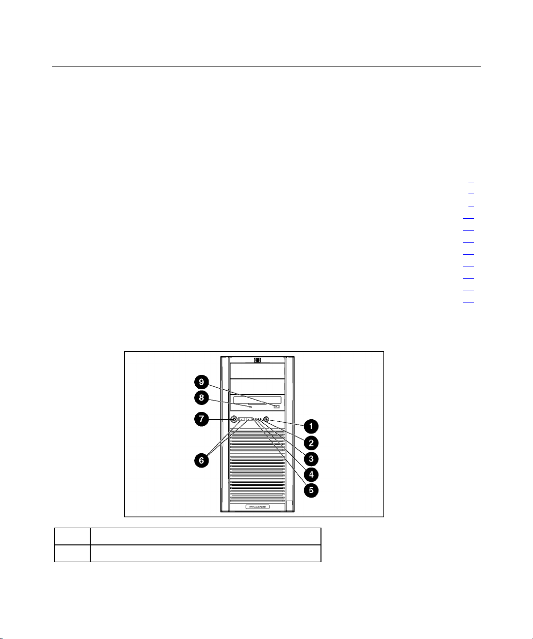
Front Panel Components
Item Description
1 Power button
Page 8
8 HP ProLiant ML310 Generation 2 Server User Guide
Item Description
2 Power LED
3 Hard Drive activity LED
4 NIC LED
5 Internal health LED
6 USB connectors (2)
7 Bezel lock
8 CD-ROM drive indicator LED
9 CD-ROM drive ejector button
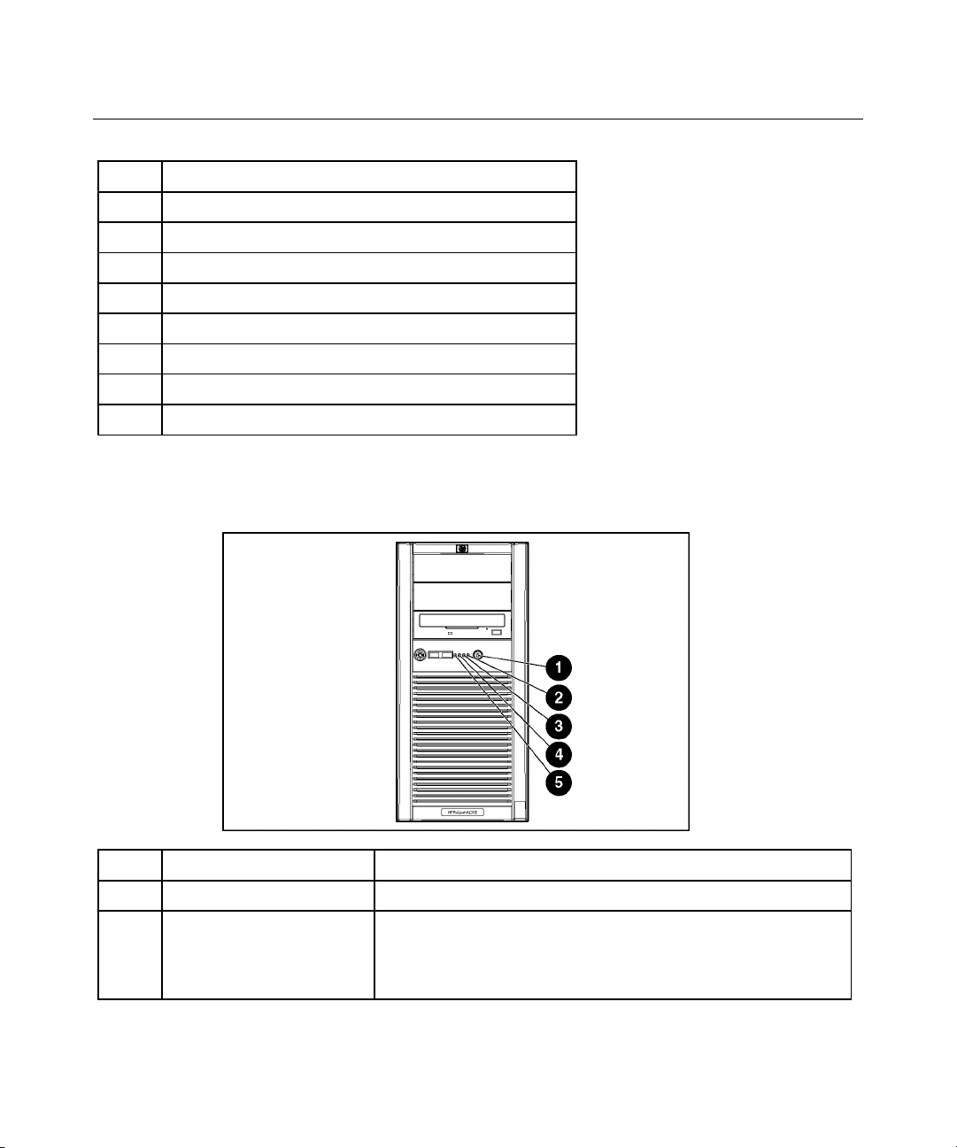
Front Panel LEDs and Buttons
Item Description Status
1 Power on/Standby button N/A
2 Power on/Standby LED Amber = System has AC power and is in standby mode
Green = System has AC power and is turned on
Off = System has no AC power
Page 9
Server Component Identification 9
Item Description Status
3 Hard drive activity LED Green = Hard drives are properly connected and functioning
Off = No hard drive activity
4 NIC link/activity LED
(embedded NIC only)
Green = Linked to network
Flashing green = Linked with activity on the network
Off = No network connection
5 Internal system health
LED
Green = Normal (system on)
Amber = System health is degraded
Red = System health is critical
Off = Normal (system off)
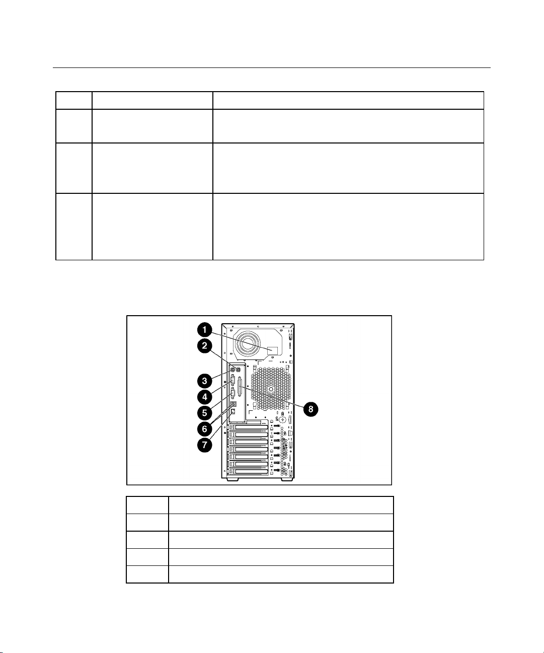
Rear Panel Components
Item Description
1 Power cord connector
2 Mouse connector
3 Keyboard connector
4 Serial connector
Page 10
10 HP ProLiant ML310 Generation 2 Server User Guide
Item Description
5 Video connector
6 USB connectors (2)
7 RJ-45 Ethernet connector
8 Parallel connector
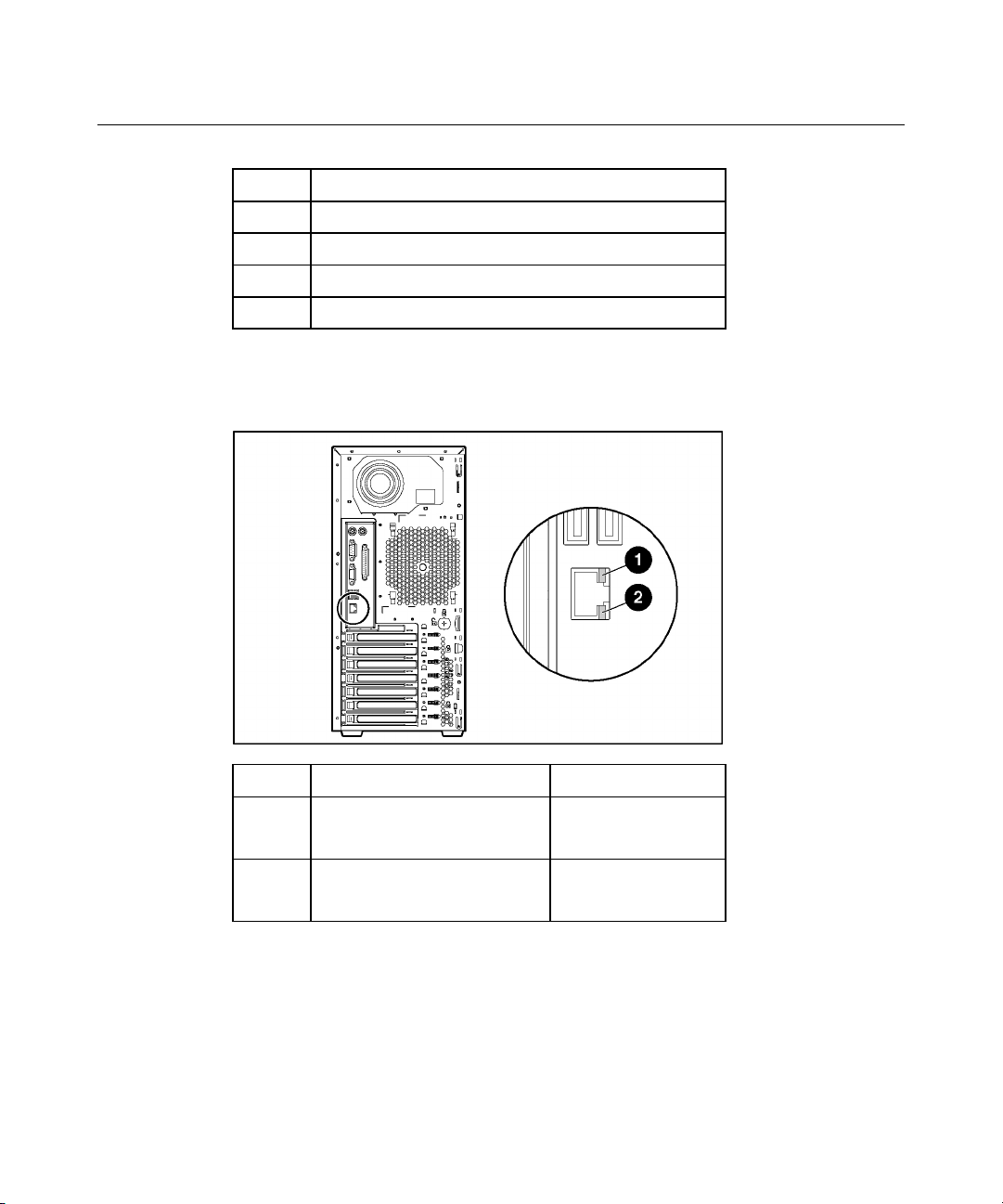
Rear Panel LEDs and Buttons
Item Description Status
1 10/100/1000 NIC link LED On = Link
Off = No link
2 10/100/1000 NIC standby
LED
Flashing = Activity
Off = No activity
Page 11
Server Component Identification 11
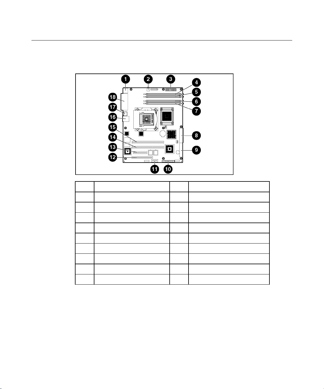
System Board Components
Item Description Item Description
1 Mouse/keyboard connectors 10 Diskette drive connector
2 Processor power connector 11 RILOE connector
3 Power supply connector 12 32-bit PCI slot
4 DIMM slot 4 (Channel B) 13 PCI Express x4 slot *
5 DIMM slot 3 (Channel B) 14 PCI-X slot 2
6 DIMM slot 2 (Channel A) 15 PCI-X slot 1
7 DIMM slot 1 (Channel A) 16 RJ-45 connector
8 IDE connector 17 USB connectors (2)
9 SATA connector 18 Serial/video/parallel ports
* x8 PCI Express cards are supported, but will run at x4 speeds.
System Maintenance Switch
The system maintenance switch (SW1) is a six-position switch that is used for
system configuration. The default position for all six positions is Off.
Page 12
12 HP ProLiant ML310 Generation 2 Server User Guide
Position Description Function
S1 Reserved Reserved
S2 Configuration
lock
Off = System configuration can
be changed
On = System configuration is
locked
S3 Reserved Reserved
S4 Reserved Reserved
S5 Password
protection
override
Off = No function
On = Clears power-on
password and administrator
password
S6 Invalidate
configuration
Off = Normal
On = ROM treats system
configuration as invalid
When the system maintenance switch position 6 is set to the On position, the
system is prepared to erase all system configuration settings from both CMOS
and NVRAM.
CAUTION: Clearing CMOS and/or NVRAM deletes
configuration information. Be sure to properly configure the server or
data loss could occur.
Page 13
Server Component Identification 13
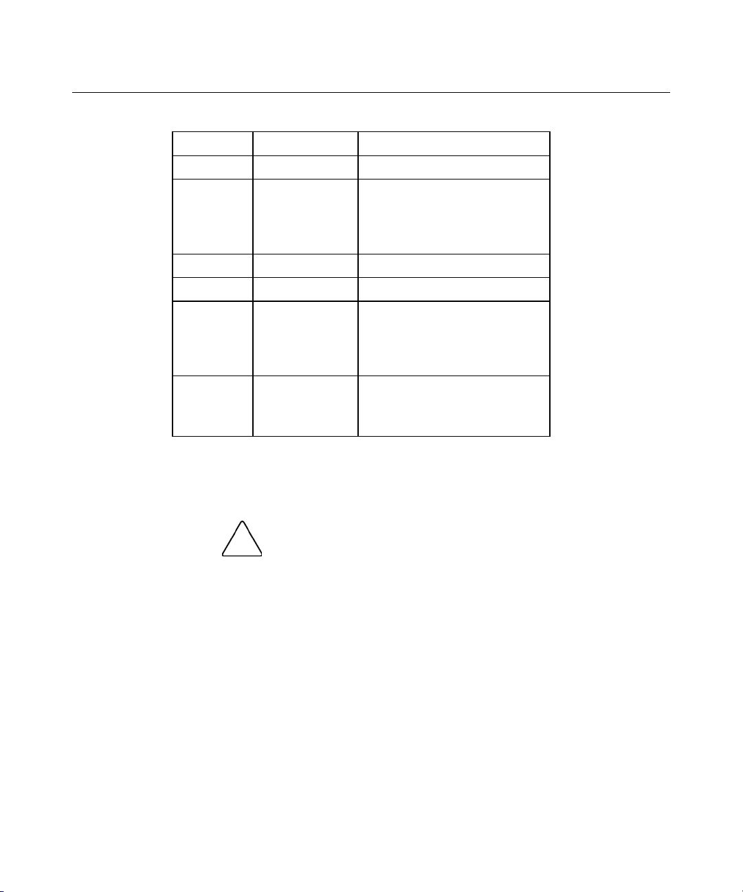
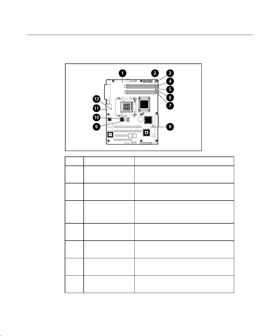
System Board LEDs
Item LED Description Status
1 PPM error Off = Normal
Amber = PPM failed or missing
2 Multibit error Off = Normal
Amber = A multibit error has occurred
3 Single bit error Off = Normal
Amber = Single bit error limit has been
exceeded
4 DIMM 4 failure Off = Normal
Amber = DIMM 4 has failed or is missing
5 DIMM 3 failure Off = Normal
Amber = DIMM 3 has failed or is missing
6 DIMM 2 failure Off = Normal
Amber = DIMM 2 has failed or is missing
7 DIMM 1 failure Off = Normal
Amber = DIMM 1 has failed or is missing
Page 14
14 HP ProLiant ML310 Generation 2 Server User Guide
Item LED Description Status
8 Power good Off = Normal
Green = Power failed
9 Processor failure Off = Normal
Amber = Processor has failed
10 System temperature
alert
11 System fan failure Off = Normal
12 Processor fan failure Off = Normal
Off = Normal
Amber = System temperature has exceeded
OS cautionary level
Amber = System fan has failed or is missing
Amber = Processor fan has failed or is
missing
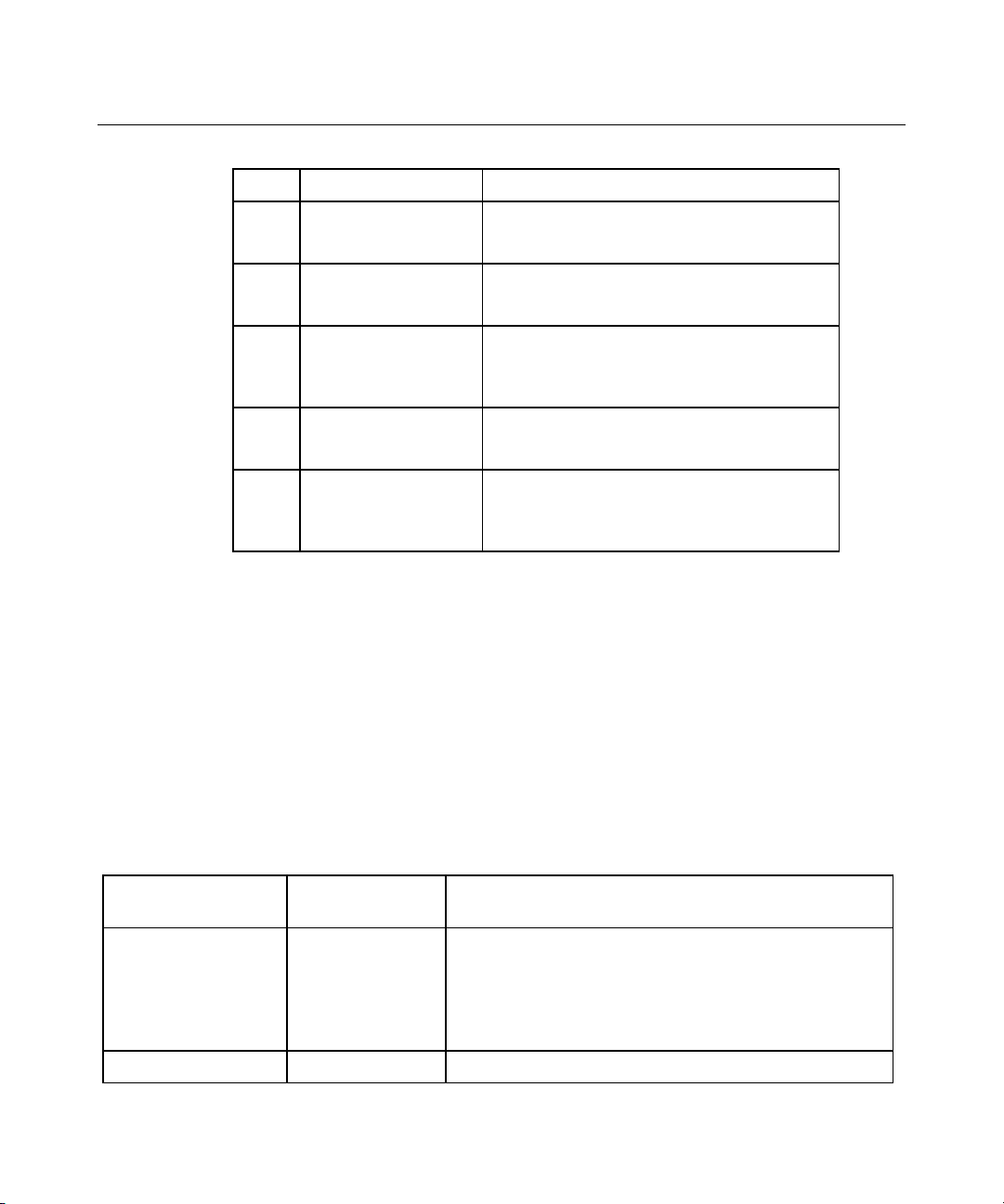
System LEDs and Internal Health LED Combinations
When the internal health LED on the front panel illuminates either amber or red,
the server is experiencing a health event. Combinations of illuminated system
LEDs and the internal health LED indicate system status.
NOTE: The system management driver must be installed in order for
the internal health LED to provide pre-failure and warranty conditions.
The front panel health LEDs indicate only the current hardware status. In some
situations, HP SIM may report server status differently than the health LEDs
because the software tracks more system attributes.
System LED and
Color
Internal Health
LED Color
Status
Processor failure,
socket X (Amber)
Amber Processor in socket X is in a pre-failure condition.
Red One or more of the following conditions may exist:
•
Processor in socket X has failed.
•
Processor X is not installed in the socket.
•
ROM detected a failed processor during POST.
Page 15

Server Component Identification 15
System LED and
Color
PPM failure, slot X
(Amber)
Internal Health
Status
LED Color
Red • • PPM in slot X has failed.
PPM is not installed in slot X, but the corresponding
processor is installed.
DIMM failure, slot X
(Amber)
Red • • DIMM in slot X has failed.
DIMM has experienced a multi-bit error.
Amber • • DIMM in slot X has reached single-bit correctable
error threshold.
DIMM in slot X is in a pre-failure condition.
DIMM bank error (all
slots in one bank,
Red The bank is not populated entirely or DIMMs do not all
match within the bank.
Amber)
DIMM failure (all
slots, Amber)
System temperature
alert (Amber)
Red • • No valid or usable memory is installed in the system.
The banks are not populated in the correct order.
Red System temperature has exceeded OS cautionary level
or critical hardware level.
Fan (Amber) Red A required fan has failed.
Power supply
Amber A redundant fan has failed.
Red The power supply backplane has failed.
backplane failure
(Amber)
Page 16
16 HP ProLiant ML310 Generation 2 Server User Guide
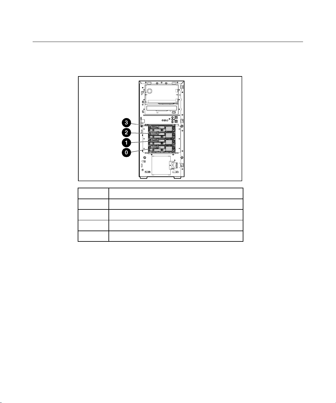
SCSI IDs
Item Description
0 SCSI ID 0
1 SCSI ID 1
2 SCSI ID 2
3 SCSI ID 3
Page 17
Server Component Identification 17
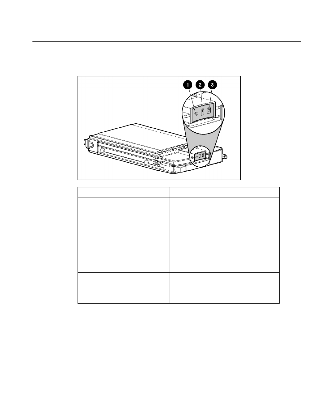
Hot-Plug SCSI Hard Drive LEDs
Item LED Description Status
1 Activity status On = Drive activity
Flashing = High activity on the drive or drive
is being configured as part of an array.
Off = No drive activity
2 Online status On = Drive is part of an array and is
currently working.
Flashing = Drive is actively online.
Off = Drive is offline.
3 Fault status On = Drive failure
Flashing = Fault-process activity
Off = No fault-process activity
Page 18

18 HP ProLiant ML310 Generation 2 Server User Guide
Hot-Plug SCSI Hard Drive LED Combinations
Activity
LED (1)
Online
LED (2)
Fault LED
(3)
Interpretation
On, off, or
flashing
On, off, or
flashing
On or off Flashing A predictive failure alert has been received for this drive.
Replace the drive as soon as possible.
On Off The drive is online and is configured as part of an array.
If the array is configured for fault tolerance and all other drives in the
array are online, and a predictive failure alert is received or a drive
capacity upgrade is in progress, you may replace the drive online.
On or
flashing
On Off Off
Flashing Off
Do not remove the drive. Removing a drive may terminate the
current operation and cause data loss.
The drive is rebuilding or undergoing capacity expansion.
Do not remove the drive.
The drive is being accessed, but (1) it is not configured as part of an
array; (2) it is a replacement drive and rebuild has not yet started; or
(3) it is spinning up during the POST sequence.
Flashing Flashing Flashing
Do not remove the drive. Removing a drive may cause data loss
in non-fault-tolerant configurations.
Either (1) the drive is part of an array being selected by an array
configuration utility; (2) Drive Identification has been selected in
HP SIM; or (3) drive firmware is being updated.
Off Off On The drive has failed and has been placed offline.
You may replace the drive.
Off Off Off Either (1) the drive is not configured as part of an array; (2) the drive
is configured as part of an array, but it is a replacement drive that is
not being accessed or being rebuilt yet; or (3) the drive is configured
as an online spare.
If the drive is connected to an array controller, you may replace the
drive online.
Page 19
Server Component Identification 19
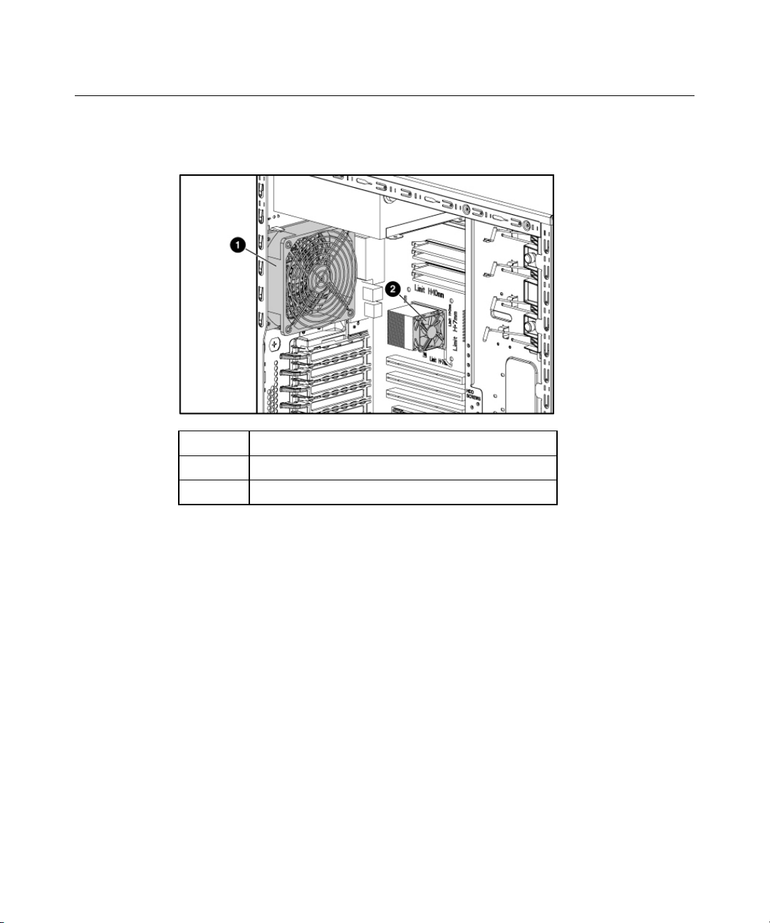
Identifying Fans
Item Description
1 System fan
2 Processor fan
Page 20

Page 21

21
Server Operations
In This Section
Powering Up the Server................................................................................................................21
Powering Down the Server...........................................................................................................21
Unlocking the Tower Bezel..........................................................................................................22
Removing the Access Panel .........................................................................................................22
Powering Up the Server
Powering Down the Server
To power up the server, press the Power On/Standby button.
WARNING: To reduce the risk of personal injury, electric
shock, or damage to the equipment, remove the power cord to
remove power from the server. The front panel Power On/Standby
button does not completely shut off system power. Portions of the
power supply and some internal circuitry remain active until AC
power is removed.
IMPORTANT: If installing a hot-plug device, it is not necessary to
power down the server.
1. Shut down the OS as directed by the OS documentation.
2. Press the Power On/Standby button to place the server in standby mode.
When the server enters standby power mode, the system power LED changes
to amber.
3. Disconnect the power cords.
The system is now without power.
Page 22
22 HP ProLiant ML310 Generation 2 Server User Guide
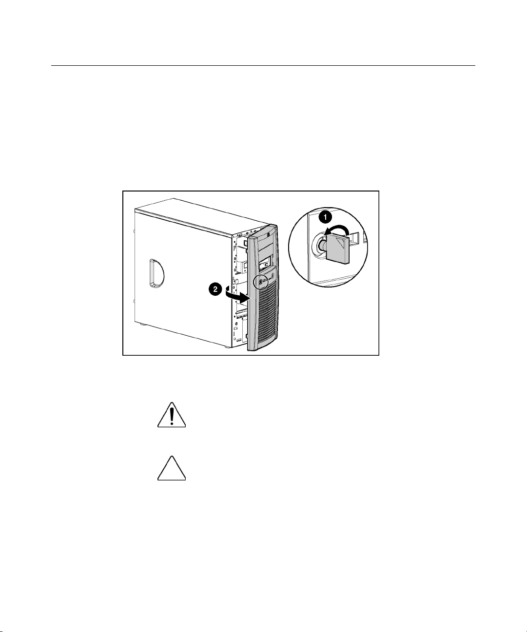
Unlocking the Tower Bezel
The removable tower bezel must be unlocked and opened before accessing the
hard drive cage and before removing the access panel. The bezel must remain
closed during normal server operations.
If necessary, remove the tower bezel.
Removing the Access Panel
WARNING: To reduce the risk of personal injury from hot
surfaces, allow the drives and the internal system components to
cool before touching them.
CAUTION: Do not operate the server for long periods without
the access panel. Operating the server without the access panel results
in improper airflow and improper cooling that can lead to thermal
damage.
1. Power down the server if performing a non-hot-plug installation or
maintenance procedure.
2. Extend or remove the server from the rack.
Page 23

Server Operations 23
3. Open the tower bezel ("Unlocking the Tower Bezel" on page 22).
4. Loosen the two captive thumbscrews.
5. Slide the access panel toward the rear of the server, and remove from the
server.
After installing hardware options, replace the access panel. Be sure that the panel
is locked into place securely before powering up the server.
Page 24

Page 25

25
Server Setup
In This Section
Optional Installation Services.......................................................................................................25
Rack Planning Resources .............................................................................................................26
Optimum Environment.................................................................................................................27
Rack Warnings and Cautions .......................................................................................................30
Identifying Tower Server Shipping Carton Contents ...................................................................33
Installing Hardware Options.........................................................................................................33
Setting up a Tower Server ............................................................................................................33
Powering Up and Configuring the Server ....................................................................................35
Installing the Operating System ...................................................................................................36
Registering the Server ..................................................................................................................36
Optional Installation Services
Delivered by experienced, certified engineers, HP Care Pack services help you
keep your servers up and running with support packages tailored specifically for
HP ProLiant systems. HP Care Packs let you integrate both hardware and
software support into a single package. A number of service level options are
available to meet your needs.
HP Care Pack Services offer upgraded service levels to expand your standard
product warranty with easy-to-buy, easy-to-use support packages that help you
make the most of your server investments. Some of the Care Pack services are:
•
Hardware support
− 6-Hour Call-to-Repair
− 4-Hour 24x7 Same Day
− 4-Hour Same Business Day
•
Software support
− Microsoft®
Page 26

26 HP ProLiant ML310 Generation 2 Server User Guide
− Linux
− HP ProLiant Essentials (HP SIM and RDP)
− VMWare
• • Integrated hardware and software support
− Critical Service
− Proactive 24
− Support Plus
− Support Plus 24
Startup and implementation services for both hardware and software
For more information on Care Packs, refer to the HP website
(http://www.hp.com/hps/carepack/servers/cp_proliant.html
Rack Planning Resources
).
The rack resource kit ships with all HP branded or Compaq branded 9000,
10000, and H9 series racks. A summary of the content of each resource follows:
• Custom Builder is a web-based service for configuring one or many racks.
Rack configurations can be created using:
− A simple, guided interface
− Build-it-yourself mode
For more information, refer to the HP website
(http://www.hp.com/products/configurator
).
• The Installing Rack Products video provides a visual overview of operations
required for configuring a rack with rack-mountable components. It also
provides the following important configuration steps:
− Planning the site
− Installing rack servers and rack options
− Cabling servers in a rack
Page 27

Server Setup 27
− Coupling multiple racks
• The Rack Products Documentation CD enables you to view, search, and print
documentation for HP and Compaq branded racks and rack options. It also
helps you set up and optimize a rack in a manner that best fits your
environment.
If you intend to deploy and configure multiple servers in a single rack, refer to
the white paper on high-density deployment on the HP website
(http://www.hp.com/products/servers/platforms
).
Optimum Environment
When installing the server, select a location that meets the environmental
standards described in this section.
Space and Airflow Requirements
Tower Server
In a tower configuration, leave at least a 7.6-cm (3-in) clearance space at the
front and back of the server for proper ventilation.
Rack Server
To allow for servicing and adequate airflow, observe the following space and
airflow requirements when deciding where to install a rack:
•
Leave a minimum clearance of 76.2 cm (30 in) in front of the rack.
•
Leave a minimum clearance of 76.2 cm (30 in) behind the rack.
•
Leave a minimum clearance of 121.9 cm (48 in) from the back of the rack to
the back of another rack or row of racks.
HP servers draw in cool air through the front and expel warm air through the
rear. Therefore, the front and rear rack doors must be adequately ventilated to
allow ambient room air to enter, and allow the warm air to escape from the
cabinet.
Page 28

28 HP ProLiant ML310 Generation 2 Server User Guide
CAUTION: To prevent improper cooling and damage to the
equipment, do not block the ventilation openings.
The 9000 and 10000 Series racks provide proper server cooling from flowthrough perforations in the front and rear doors that provide 64 percent open area
for ventilation.
CAUTION: When using a Compaq branded 7000 Series rack,
you must install the high airflow rack door insert [P/N 327281-B21 (42U)
or P/N 157847-B21 (22U)] to provide proper front-to-back airflow and
cooling.
CAUTION: If a third-party rack is used, observe the following
additional requirements to ensure adequate airflow and to prevent
damage to the equipment:
• • Front and rear doors—If the 42U rack includes closing front and rear
doors, you must allow 5,350 sq cm (830 sq in) of holes evenly
distributed from top to bottom to permit adequate airflow (equivalent
to the required 64 percent open area for ventilation).
Side—The clearance between the installed rack component and the
side panels of the rack must be a minimum of 7 cm (2.75 in).
When vertical space in the rack is not filled by a server or rack component, the
gaps between the components cause changes in airflow through the rack and
across the servers. Cover all gaps with blanking panels to maintain proper
airflow.
CAUTION: Always use blanking panels to fill empty vertical
spaces in the rack. This arrangement ensures proper airflow. Using a
rack without blanking panels results in improper cooling that can lead to
thermal damage.
Temperature Requirements
To ensure continued safe and reliable equipment operation, install or position the
system in a well-ventilated, climate-controlled environment.
Page 29

Server Setup 29
The maximum recommended ambient operating temperature (TMRA) for most
server products is 35°C (95°F). The temperature in the room where the rack is
located must not exceed 35°C (95°F).
CAUTION: To reduce the risk of damage to the equipment
when installing third-party options:
• • Do not permit optional equipment to impede airflow around the
server or to increase the internal rack temperature beyond the
maximum allowable limits.
Do not exceed the manufacturer’s TMRA.
Power Requirements
Installation of this equipment must comply with local and regional electrical
regulations governing the installation of information technology equipment by
licensed electricians. This equipment is designed to operate in installations
covered by NFPA 70, 1999 Edition (National Electric Code) and NFPA-75, 1992
(code for Protection of Electronic Computer/Data Processing Equipment). For
electrical power ratings on options, refer to the product rating label or the user
documentation supplied with that option.
WARNING: To reduce the risk of personal injury, fire, or
damage to the equipment, do not overload the AC supply branch
circuit that provides power to the rack. Consult the electrical
authority having jurisdiction over wiring and installation
requirements of your facility.
CAUTION: Protect the server from power fluctuations and
temporary interruptions with a regulating uninterruptible power supply
(UPS). This device protects the hardware from damage caused by
power surges and voltage spikes and keeps the system in operation
during a power failure.
When installing more than one server, you may need to use additional power
distribution devices to safely provide power to all devices. Observe the following
guidelines:
• Balance the server power load between available AC supply branch circuits.
Page 30

30 HP ProLiant ML310 Generation 2 Server User Guide
•
Do not allow the overall system AC current load to exceed 80 percent of the
branch circuit AC current rating.
•
Do not use common power outlet strips for this equipment.
•
Provide a separate electrical circuit for the server.
Electrical Grounding Requirements
The server must be grounded properly for proper operation and safety. In the
United States, you must install the equipment in accordance with NFPA 70, 1999
Edition (National Electric Code), Article 250, as well as any local and regional
building codes. In Canada, you must install the equipment in accordance with
Canadian Standards Association, CSA C22.1, Canadian Electrical Code. In all
other countries, you must install the equipment in accordance with any regional
or national electrical wiring codes, such as the International Electrotechnical
Commission (IEC) Code 364, parts 1 through 7. Furthermore, you must be sure
that all power distribution devices used in the installation, such as branch wiring
and receptacles, are listed or certified grounding-type devices.
Because of the high ground-leakage currents associated with multiple servers
connected to the same power source, HP recommends the use of a PDU that is
either permanently wired to the building’s branch circuit or includes a
nondetachable cord that is wired to an industrial-style plug. NEMA locking-style
plugs or those complying with IEC 60309 are considered suitable for this
purpose. Using common power outlet strips for the server is not recommended.
Rack Warnings and Cautions
WARNING: To reduce the risk of personal injury or
damage to the equipment, be sure that:
Page 31
Server Setup 31
The leveling jacks are extended to the floor. •
•
The full weight of the rack rests on the leveling jacks.
•
The stabilizing feet are attached to the rack if it is a single-rack
installation.
•
The racks are coupled together in multiple-rack installations.
•
Only one component is extended at a time. A rack may become
unstable if more than one component is extended for any
reason.
WARNING: To reduce the risk of personal injury or
equipment damage when unloading a rack:
At least two people are needed to safely unload the rack from
•
the pallet. An empty 42U rack can weigh as much as 115 kg
(253 lb), can stand more than 2.1 m (7 ft) tall, and may become
unstable when being moved on its casters.
• Never stand in front of the rack when it is rolling down the ramp
from the pallet. Always handle the rack from both sides.
WARNING: When installing a server in a telco rack, be
sure that the rack frame is adequately secured to the top and
bottom of the building structure.
WARNING: This server is very heavy. To reduce the risk
of personal injury or damage to the equipment:
Page 32

32 HP ProLiant ML310 Generation 2 Server User Guide
Observe local occupational health and safety requirements and
•
guidelines for manual material handling.
• • Get help to lift and stabilize the product during installation or
removal, especially when the product is not fastened to the
rails. When the server weighs more than 22.5 kg (50 lb), at least
two people must lift the server into the rack together. A third
person may be required to help align the server if the server is
installed higher than chest level.
Use caution when installing the server in or removing the
server from the rack; it is unstable when not fastened to the
rails.
WARNING: To reduce the risk of personal injury from hot
surfaces, allow the drives and the internal system components to
cool before touching them.
WARNING: To reduce the risk of personal injury, electric
shock, or damage to the equipment, remove the power cord to
remove power from the server. The front panel Power On/Standby
button does not completely shut off system power. Portions of the
power supply and some internal circuitry remain active until AC
power is removed.
CAUTION: Protect the server from power fluctuations and
temporary interruptions with a regulating uninterruptible power supply
(UPS). This device protects the hardware from damage caused by
power surges and voltage spikes and keeps the system in operation
during a power failure.
Page 33

Server Setup 33
CAUTION: Do not operate the server for long periods without
the access panel. Operating the server without the access panel results
in improper airflow and improper cooling that can lead to thermal
damage.
Identifying Tower Server Shipping Carton Contents
Unpack the server shipping carton and locate the materials and documentation
necessary for installing the server.
The contents of the server shipping carton include:
•
Server
•
Power cord
•
Keyboard (Not all SKUs)
•
Mouse
•
Hardware documentation, Documentation CD, and software products
In addition to the supplied items, you may need:
•
Hardware options
•
Operating system or application software
•
PDU
Installing Hardware Options
Install any hardware options before initializing the server. For options installation
information, refer to the option documentation. For server-specific information,
refer to "Hardware Options Installation (on page 37
Setting up a Tower Server
Follow the steps in this section to set up a tower model server.
)."
Page 34

34 HP ProLiant ML310 Generation 2 Server User Guide
1. Connect peripheral devices to the server.
WARNING: To reduce the risk of electric shock, fire, or
damage to the equipment, do not plug telephone or
telecommunications connectors into RJ-45 connectors.
IMPORTANT: If the RILOE II board is installed in the server, be sure
that you attach the video cable to the video connector on the rear of the
RILOE II board. The standard video connector on the server rear panel
is not used when the RILOE II board is installed. For more information,
refer to the HP Remote Insight Lights-Out Edition II User Guide.
Item Description
1 Power cord connector
2 Mouse connector
3 Keyboard connector
4 Serial connector
5 Video connector
6 USB connectors (2)
7 RJ-45 Ethernet connector
8 Parallel connector
2. Connect the power cord to the back of the server.
Page 35

Server Setup 35
3. Connect the power cord to the AC power source.
WARNING: To reduce the risk of electric shock or damage
to the equipment:
Do not disable the power cord grounding plug. The grounding
•
plug is an important safety feature.
•
Plug the power cord into a grounded (earthed) electrical outlet
that is easily accessible at all times.
•
Unplug the power cord from the power supply to disconnect
power to the equipment.
•
Do not route the power cord where it can be walked on or
pinched by items placed against it. Pay particular attention to
the plug, electrical outlet, and the point where the cord extends
from the server.
Powering Up and Configuring the Server
To power up the server, press the Power On/Standby button.
While the server boots, RBSU and the ORCA utility are automatically
configured to prepare the server for operating system installation. To configure
these utilities manually:
•
Press the F8 key when prompted during the array controller initialization to
configure the array controller using ORCA.
•
Press the F9 key when prompted during the boot process to change the server
settings, such as the settings for language and operating system, using RBSU.
The system is set up by default for the English language and a Microsoft®
Windows® 2000 installation.
For more information on the automatic configuration, refer to the ROM-Based
Setup Utility User Guide located on the Documentation CD.
Page 36

36 HP ProLiant ML310 Generation 2 Server User Guide
Installing the Operating System
To operate properly, the server must have a supported operating system. For the
latest information on supported operating systems, refer to the HP website
(http://www.hp.com/go/supportos
Two methods are available to install an operating system on the server:
• • SmartStart assisted installation—Insert the SmartStart CD into the CD-ROM
drive and reboot the server.
Manual installation—Insert the operating system CD into the CD-ROM drive
and reboot the server. This process may require you to obtain additional
drivers from the HP website (http://www.hp.com/support
Follow the on-screen instructions to begin the installation process.
For information on using these installation paths, refer to the SmartStart
installation poster in the HP ProLiant Essentials Foundation Pack, included with
the server.
).
).
Registering the Server
To register a server, refer to the registration card in the HP ProLiant Essentials
Foundation Pack or the HP Registration website (http://register.hp.com
).
Page 37

37
Hardware Options Installation
In This Section
Introduction ..................................................................................................................................37
Processor and Heatsink.................................................................................................................38
Memory Options...........................................................................................................................41
Hard Drive Options ......................................................................................................................43
SAS Controller .............................................................................................................................50
Removing the CD-ROM Drive.....................................................................................................51
DVD-ROM Drive.........................................................................................................................52
Optional Diskette Drive................................................................................................................53
Expansion Boards.........................................................................................................................54
Introduction
If more than one option is being installed, read the installation instructions for all
the hardware options and identify similar steps to streamline the installation
process.
WARNING: To reduce the risk of personal injury from hot
surfaces, allow the drives and the internal system components to
cool before touching them.
CAUTION: To prevent damage to electrical components,
properly ground the server before beginning any installation procedure.
Improper grounding can cause electrostatic discharge.
Page 38
38 HP ProLiant ML310 Generation 2 Server User Guide
Processor and Heatsink
CAUTION: Be sure that you have the current version of the
system ROM. Failure to flash the ROM with the correct version before
installing or replacing the processor causes system failure. For the most
current version of the ROM, go to the HP website
(http://www.hp.com/support
To remove the component:
1. Power down the server.
).
2. Remove the access panel ("Removing the Access Panel" on page 22
3. Disconnect the fan cable from the system board.
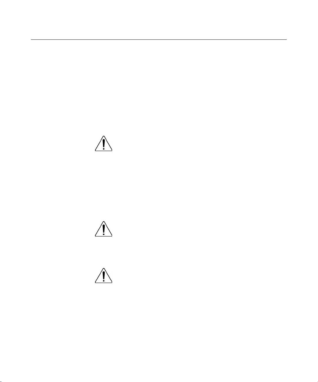
4. Loosen the four heatsink retaining screws.
CAUTION: Heatsink retaining screws should be removed in
diagonally opposite pairs (in an "X" pattern).
CAUTION: The pins on the processor socket are very fragile.
Any damage to them may require replacing the system board.
5. Remove the heatsink fan assembly
).
Page 39

Hardware Options Installation 39
6. Release the processor locking lever, and remove the processor.
To replace the component:
1. Open the processor retaining bracket.
2. Place the processor into the processor socket.
3. Close the processor locking lever.
CAUTION: To prevent possible server malfunction or damage
to the equipment, be sure to align the processor pins with the
corresponding holes in the socket.
Page 40

40 HP ProLiant ML310 Generation 2 Server User Guide
CAUTION: To prevent possible server malfunction or damage
to the equipment, be sure to completely close the processor locking
lever.
4. Prepare the heatsink for installation:
a. If reusing the heatsink, clean the bottom of the heatsink with the
provided alcohol pad then apply a thin layer of thermal grease to the top
of the processor.
NOTE: HP recommends ShinEtsu G751 thermal grease compound for
this server.
b. If installing a new heatsink, remove the protective covering.
5. Install the heatsink fan assembly.
6. Tighten the four heatsink retaining screws.
Page 41

Hardware Options Installation 41
CAUTION: Heatsink retaining screws should be tightened in
diagonally opposite pairs (in an "X" pattern).
7. Connect the fan cable to the system board.
8. Replace the access panel ("Removing the Access Panel" on page 22
Memory Options
You can expand server memory by installing PC-3200 DDR SDRAM DIMMs
with Advanced ECC. The system supports up to four DIMMs for a maximum of
4 GB.
Refer to "System Board Components (on page 11
bank assignments.
DIMM Installation Guidelines
Observe the following guidelines when installing additional memory:
• • DIMMs installed in the server must be Unbuffered DDR DRAM, 2.5 volts,
64 bits wide, and ECC.
If only a single DIMM is installed, it must be installed in slot 1A.
).
)" for DIMM slot locations and
Page 42

42 HP ProLiant ML310 Generation 2 Server User Guide
•
All DIMMs installed must be the same speed.
BIOS detects the DIMM population and sets the system as follows:
•
Single-channel mode: DIMMs installed in one channel only.
•
Dual-channel asymmetric mode: DIMMs installed in both channels but of
unequal capacities per channel.
•
Dual-channel interleaved mode: DIMMs installed in both channels with
equal channel capacities.
The following table lists some, but not all, possible configurations. For best
performance, HP recommends dual-channel interleaved mode configurations.
Slot 1A Slot 2A Slot 3B Slot 4B Total Memory Mode
128 MB — — — 128 MB Single-channel
128 MB — 128 MB — 256 MB Dual-channel interleaved
128 MB 128 MB 128 MB — 384 MB Dual-channel
asymmetric
128 MB 128 MB 128 MB 128 MB 512 MB Dual-channel interleaved
256 MB — — — 256 MB Single-channel
256 MB — 256 MB — 512 MB Dual-channel interleaved
512 MB — — — 512 MB Single-channel
512 MB — 512 MB — 1 GB Dual-channel interleaved
1 GB — — — 1 GB Single-channel
1 GB — 1 GB — 2 GB Dual-channel interleaved
1 GB 1 GB 1 GB — 3 GB Dual-channel
asymmetric
1 GB 1 GB 1 GB 1 GB 4 GB Dual-channel interleaved
Installing DIMMs
1. Power down the server.
2. Remove the access panel ("Removing the Access Panel" on page 22
).
Page 43

Hardware Options Installation 43
3. Open the DIMM slot latches.
4. Install the DIMM.
5. Install the access panel ("Removing the Access Panel" on page 22
Hard Drive Options
The server supports non-hot-plug SCSI hard drives, hot-plug SAS hard drives,
and hot-plug SATA hard drives. Hot-plug SATA hard drives are interchangeable
with hot-plug SAS hard drives when the optional SAS controller ("SAS
Controller" on page 50) is installed.
Hard Drive Model Drives Supported Additional Required
Non-hot-plug SATA SATA N/A
Non-hot-plug SCSI SCSI N/A
Hot-plug SATA/SAS SATA, SAS SAS controller required
).
Components
for hot-plug SAS hard
drive
Page 44

44 HP ProLiant ML310 Generation 2 Server User Guide
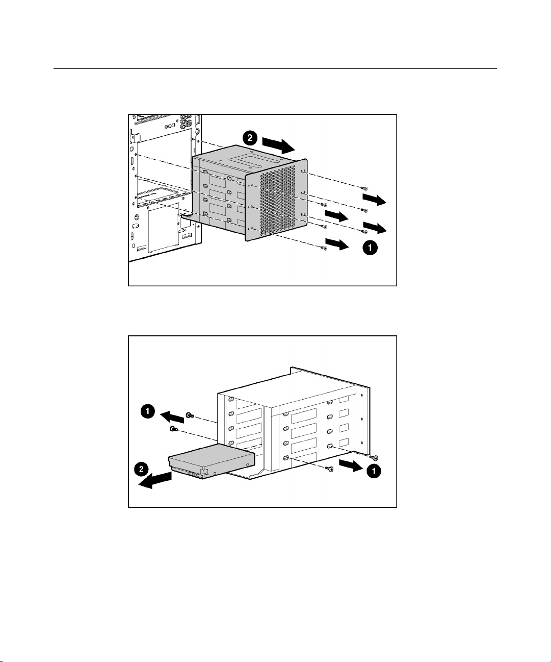
Non-Hot-Plug SATA Hard Drive
To remove the component:
1. Power down the server.
2. Remove the access panel ("Removing the Access Panel" on page 22
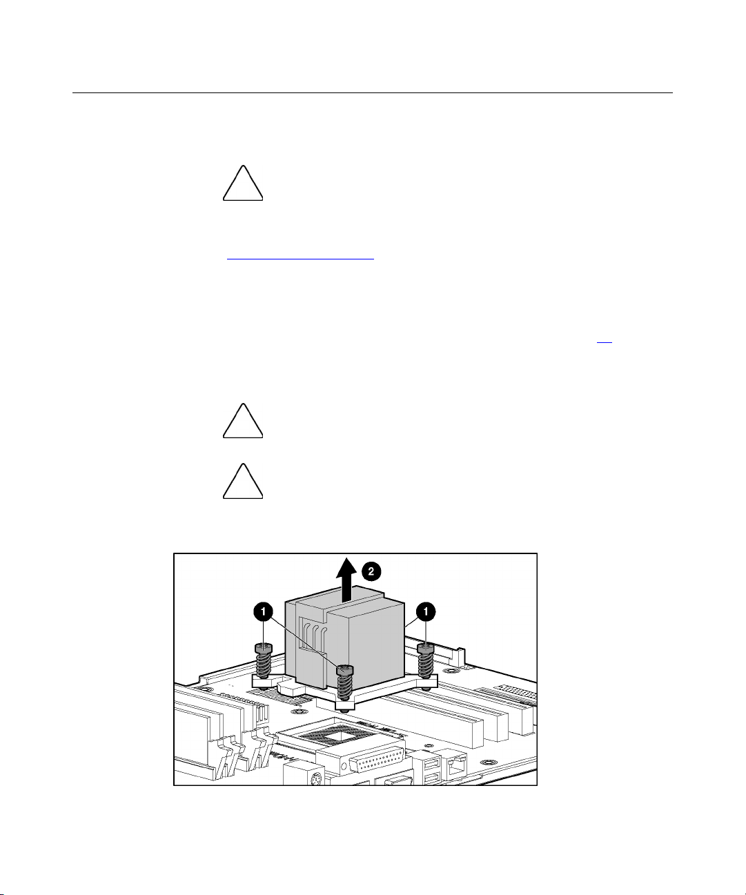
3. Disconnect the power and data cables from the rear of the hard drive.
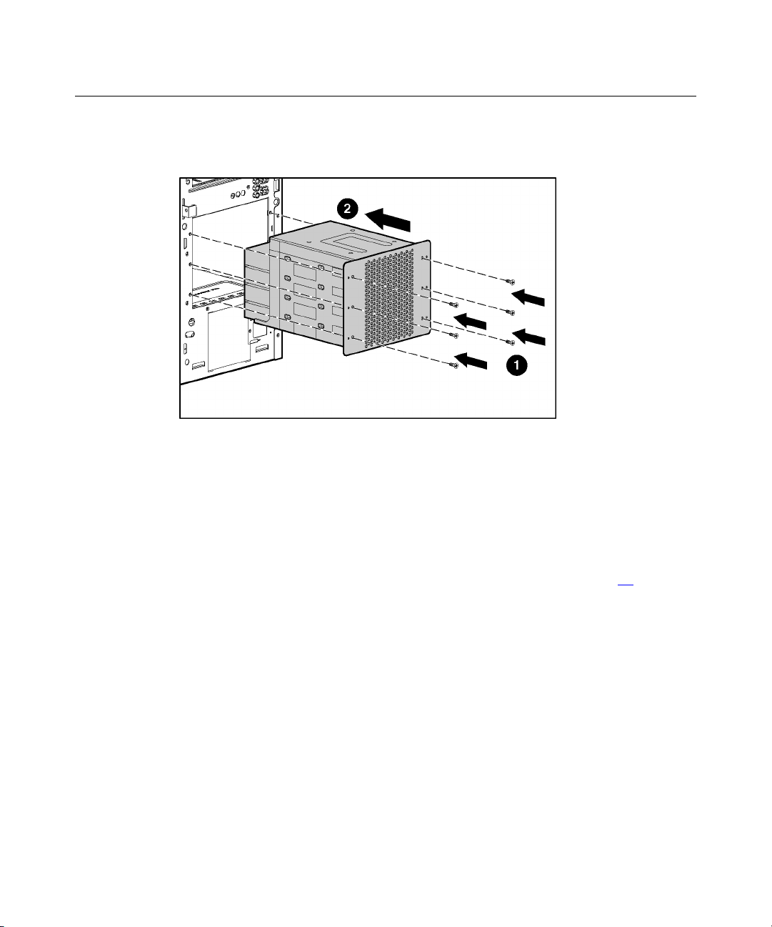
4. Remove the drive cage from the chassis.
5. Remove the six Torx screws that secure the drive cage to the chassis.
).
Page 45
Hardware Options Installation 45
6. Remove the hard drive.
To replace the component:
1. Install the non-hot-plug SATA hard drive into the drive cage.
Page 46
46 HP ProLiant ML310 Generation 2 Server User Guide
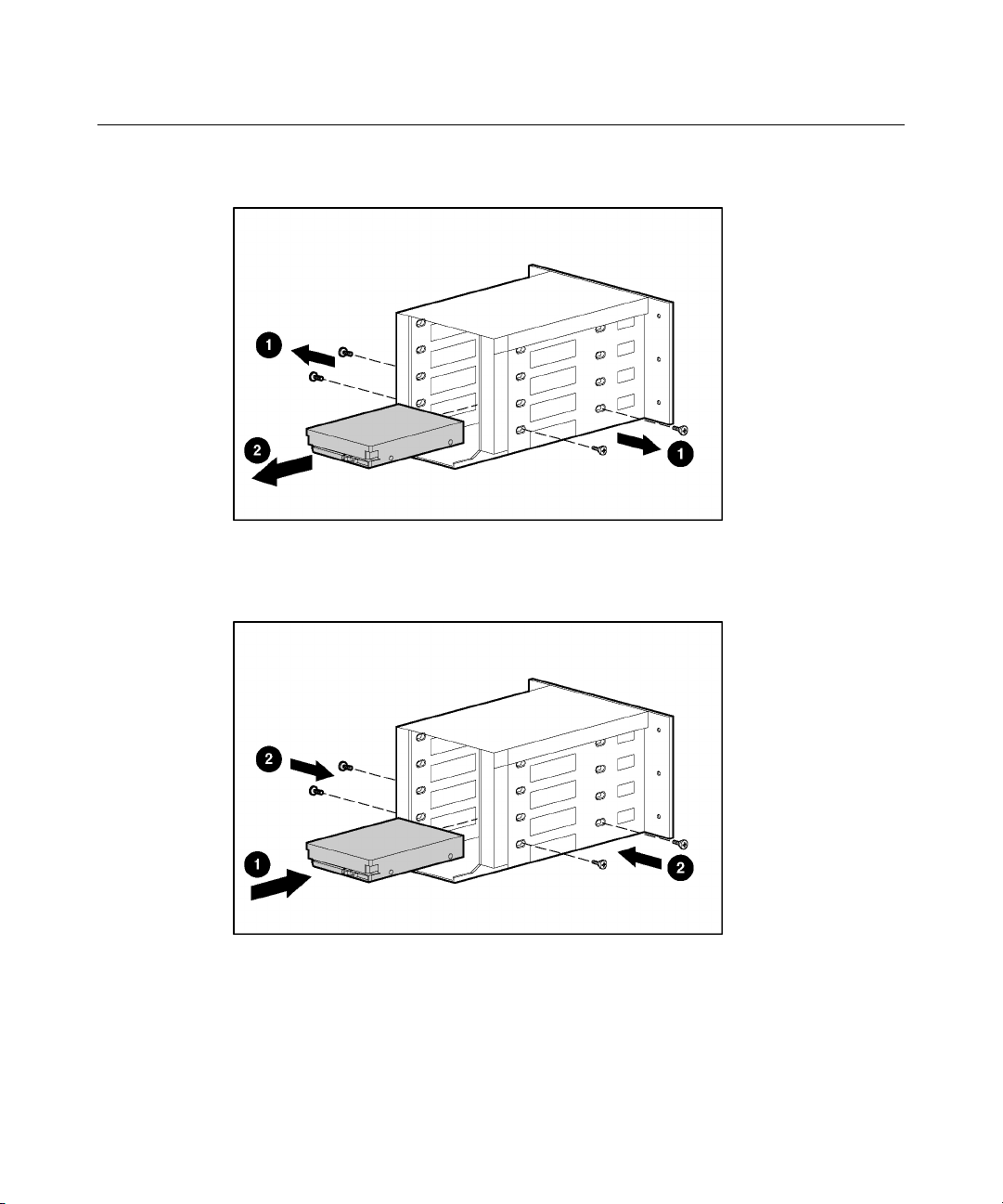
2. Install the drive cage into the chassis, and secure with the six (6) Torx
screws.
3. Connect the data and power cables to the rear of the installed hard drive.
Non-Hot-Plug SCSI Hard Drive
To remove the component:
1. Power down the server.
2. Remove the access panel ("Removing the Access Panel" on page 22
).
3. Disconnect the power and data cables from the rear of the hard drive.
Page 47
Hardware Options Installation 47
4. Remove the drive cage from the chassis.
5. Remove the six Torx screws that secure the drive cage to the chassis.
6. Remove the hard drive.
To replace the component:
Page 48

48 HP ProLiant ML310 Generation 2 Server User Guide
1. Install the non-hot-plug SCSI hard drive into the drive cage.
2. Install the drive cage into the chassis, and secure with the six Torx screws.
3. Connect the data and power cables to the rear of the installed hard drive.
Page 49

Hardware Options Installation 49
Hot-Plug SATA and SAS Hard Drives
Hot-plug SATA and hot-plug SAS hard drives can be used interchangeably when
a SAS controller is installed. The SATA controller is embedded, but before
installing a hot-plug SAS hard drive, install the SAS controller ("SAS
Controller" on page 50
To remove the component:
CAUTION: To prevent improper cooling and thermal damage,
do not operate the server unless all bays are populated with either a
component or a blank.
1. Determine the status of the hard drive from the hot-plug hard drive LEDs
("Hot-Plug SCSI Hard Drive LED Combinations" on page 18
SCSI Hard Drive LEDs" on page 17
2. Back up all server data on the hard drive.
3. Disconnect the cables from the hot-plug SATA or SAS drive cage.
4. Remove the hard drive.
).
, "Hot-Plug
).
To replace the component:
1. Remove the existing hard drive blank or hard drive from the drive bay.
Page 50

50 HP ProLiant ML310 Generation 2 Server User Guide
2. Install the hard drive.
3. Determine the status of the hard drive from the hot-plug hard drive LEDs
("Hot-Plug SCSI Hard Drive LED Combinations" on page 18
SCSI Hard Drive LEDs" on page 17
4. Resume normal server operations.
).
, "Hot-Plug
SAS Controller
To install the component:
1. Power down the server.
2. Remove the access panel ("Removing the Access Panel" on page 22).
3. Remove the expansion slot cover ("Expansion Slot Cover" on page 54
).
Page 51
Hardware Options Installation 51
4. Install the SAS controller, and press it down to seat.
5. Disconnect the SAS cable from the system board and connect it to the SAS
controller.
6. Be sure the SAS cable is properly connected to the SAS controller and drive
backplane.
Removing the CD-ROM Drive
Before installing the drive option kit, the CD-ROM drive must be removed.
To remove the component:
1. Power down the server.
2. Remove the access panel ("Removing the Access Panel" on page 22
3. Disconnect the cables from the rear of the CD-ROM drive.
).
Page 52

52 HP ProLiant ML310 Generation 2 Server User Guide
4. Push up on the release lever and push the drive partially out through the front
of the server.
5. Remove the CD-ROM drive.
CAUTION: To prevent improper cooling and thermal damage,
do not operate the server unless all bays are populated with either a
component or a blank.
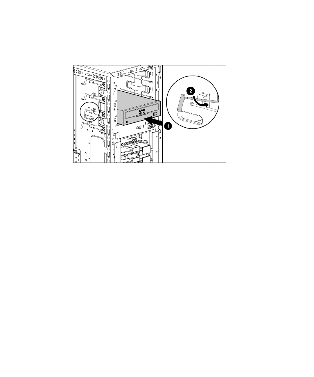
DVD-ROM Drive
To install the component:
1. Power down the server.
2. Remove the access panel ("Removing the Access Panel" on page 22
).
Page 53
Hardware Options Installation 53
3. Slide the DVD-ROM drive into the DVD-ROM drive bay.
4. Secure the DVD-ROM drive cable to the DVD-ROM drive cable connector
on the system board.
Optional Diskette Drive
When using operating systems that support USB, the server supports USB
devices, including, but not limited to:
•
CD-ROM drives
•
Diskette drives
•
Keyboard
•
Mouse
For other operating systems, the ROM provides USB support for a keyboard,
mouse, and diskette drives, which do not support USB, but not for CD-ROM
drives.
ROM legacy USB support is available during POST and while the operating
system is running. The maximum device support is two USB keyboards, two
USB mouse devices, and one layer of hubs.
To install the component:
Page 54

54 HP ProLiant ML310 Generation 2 Server User Guide
1. Power down the server.
2. Slide the diskette drive into the diskette drive bay.
3. Secure the diskette drive cable to the diskette drive cable connector on the
system board.
Expansion Boards
The server supports PCI, PCI-X, and PCI Express expansion boards.
Slot Expansion
card type
1 PCI-X 64 bit, 3.3 volt 100 MHz
2 PCI-X 64 bit, 3.3 volt 100 MHz
3 PCI Express x8 x4
4 PCI 32-bit, 3.3 volt 33 MHz
Expansion Slot Cover
1. Power down the server.
2. Remove the access panel ("Removing the Access Panel" on page 22
Connector Capable speed
).
Page 55

Hardware Options Installation 55
3. Remove the expansion slot cover.
CAUTION: To prevent improper cooling and thermal damage,
do not operate the server unless all PCI slots have either an expansion
slot cover or an expansion board installed.
To replace the component, reverse the removal procedure.
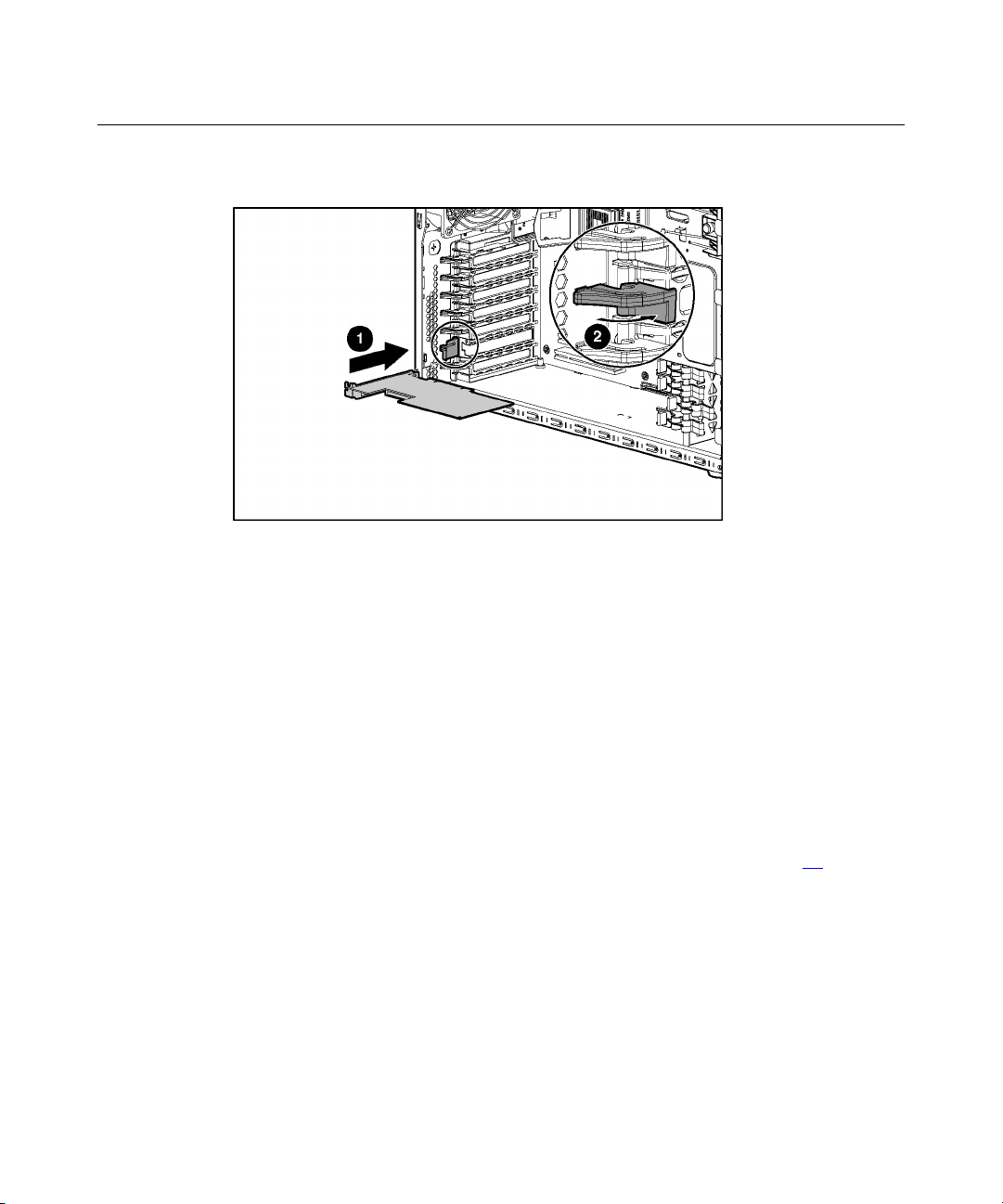
Installing Expansion Boards
CAUTION: To prevent damage to the server or expansion
boards, power down the server and remove all AC power cords before
removing or installing the expansion boards.
1. Power down the server.
2. Remove the access panel ("Removing the Access Panel" on page 22
3. Remove the expansion slot cover ("Expansion Slot Cover" on page 54
).
).
Page 56

56 HP ProLiant ML310 Generation 2 Server User Guide
4. Install the expansion board, and press it down to seat.
5. Connect any required internal or external cables to the expansion board.
Refer to the documentation that ships with the expansion board.
Page 57

57
Server Cabling
In This Section
Server Cabling..............................................................................................................................57
Hot-Plug SCSI Cabling ................................................................................................................57
Non-Hot-Plug SCSI Cabling ........................................................................................................58
Hot-Plug SATA Cabling ..............................................................................................................59
Non-Hot-Plug SATA Cabling ......................................................................................................59
SAS Cabling .................................................................................................................................60
Server Cabling
This section provides guidelines that help you make informed decisions about
cabling the server and hardware options to optimize performance.
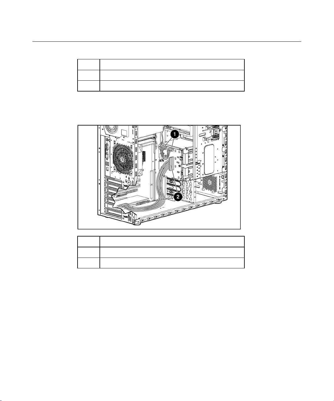
Hot-Plug SCSI Cabling
Item Cable Description
1 Power cable
Page 58
58 HP ProLiant ML310 Generation 2 Server User Guide
Item Cable Description
2 SCSI cable
Non-Hot-Plug SCSI Cabling
Item Cable Description
1 SCSI cable
2 Power cable
Page 59

Server Cabling 59
Hot-Plug SATA Cabling
Item Cable Description
1 Power cable
2 SATA cable
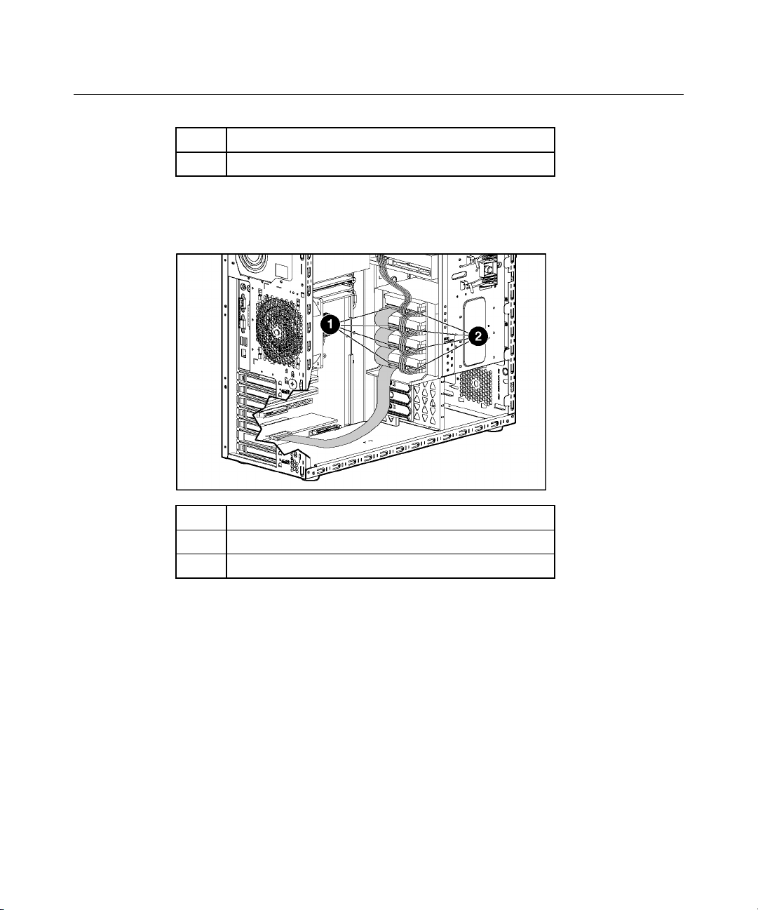
Non-Hot-Plug SATA Cabling
Page 60
60 HP ProLiant ML310 Generation 2 Server User Guide
Item Cable Description
1 SATA cable
2 Power cable
SAS Cabling
Item Cable Description
1 Power cable
2 SAS cable
Page 61

61
Server Software and Configuration Utilities
In This Section
Configuration Tools......................................................................................................................61
Management Tools .......................................................................................................................67
Diagnostic Tools...........................................................................................................................72
Keeping the System Current.........................................................................................................73
Configuration Tools
List of Tools:
SmartStart Software......................................................................................................................61
HP ROM-Based Setup Utility ......................................................................................................63
Array Configuration Utility..........................................................................................................65
Option ROM Configuration for Arrays........................................................................................66
HP ProLiant Essentials Rapid Deployment Pack .........................................................................66
Re-Entering the Server Serial Number and Product ID................................................................67
SmartStart Software
SmartStart is a collection of software that optimizes single-server setup,
providing a simple and consistent way to deploy server configuration. SmartStart
has been tested on many ProLiant server products, resulting in proven, reliable
configurations.
SmartStart assists the deployment process by performing a wide range of
configuration activities, including:
•
Configuring hardware using embedded configuration utilities, such as RBSU
and ORCA
•
Preparing the system for installing "off-the-shelf" versions of leading
operating system software
•
Installing optimized server drivers, management agents, and utilities
automatically with every assisted installation
Page 62

62 HP ProLiant ML310 Generation 2 Server User Guide
• Testing server hardware using the Insight Diagnostics Utility ("HP Insight
Diagnostics" on page 73
)
• • Installing software drivers directly from the CD. With systems that have
internet connection, the SmartStart Autorun Menu provides access to a
complete list of ProLiant system software.
Enabling access to the Array Configuration Utility (on page 65
Diagnostics Utility ("Array Diagnostic Utility" on page 72
(on page 69
SmartStart is included in the HP ProLiant Essentials Foundation Pack. For more
information about SmartStart software, refer to the HP ProLiant Essentials
Foundation Pack or the HP website (http://www.hp.com/servers/smartstart
SmartStart Scripting Toolkit
The SmartStart Scripting Toolkit is a server deployment product that delivers an
unattended automated installation for high-volume server deployments. The
SmartStart Scripting Toolkit is designed to support ProLiant BL, ML, and DL
servers. The toolkit includes a modular set of utilities and important
documentation that describes how to apply these new tools to build an automated
server deployment process.
Using SmartStart technology, the Scripting Toolkit provides a flexible way to
create standard server configuration scripts. These scripts are used to automate
many of the manual steps in the server configuration process. This automated
server configuration process cuts time from each server deployed, making it
possible to scale server deployments to high volumes in rapid fashion.
For more information, and to download the SmartStart Scripting Toolkit, refer to
the HP website (http://www.hp.com/servers/sstoolkit
), Array
), and Erase Utility
)
).
).
Page 63

Server Software and Configuration Utilities 63
Configuration Replication Utility
ConRep is shipped in the SmartStart Scripting Toolkit and is a program that
works with RBSU to replicate hardware configuration on ProLiant servers. This
utility is run during State 0, Run Hardware Configuration Utility, when doing a
scripted server deployment. ConRep reads the state of the system environment
variables to determine the configuration and then writes the results on an editable
script file. This file can then be deployed across multiple servers with similar
hardware and software components. For more information, refer to the
SmartStart Scripting Toolkit User Guide on the HP website
(http://h18004.www1.hp.com/products/servers/management/toolkit/documentatio
n.html).
HP ROM-Based Setup Utility
RBSU, an embedded configuration utility, performs a wide range of
configuration activities that may include:
•
Configuring system devices and installed options
•
Displaying system information
Using RBSU
•
Selecting the primary boot controller
•
Configuring memory options
•
Language selection
For more information on RBSU, refer to the HP ROM-Based Setup Utility User
Guide on the Documentation CD or the HP website
(http://www.hp.com/servers/smartstart
).
The first time you power up the server, the system prompts you to enter RBSU
and select a language. Default configuration settings are made at this time and
can be changed later. Most of the features in RBSU are not required to set up the
server.
To navigate RBSU, use the following keys:
Page 64

64 HP ProLiant ML310 Generation 2 Server User Guide
•
To access RBSU, press the F9 key during power up when prompted in the
upper right corner of the screen.
•
To navigate the menu system, use the arrow keys.
•
To make selections, press the Enter key.
IMPORTANT: RBSU automatically saves settings when you press the
Enter key. The utility does not prompt you for confirmation of settings
before you exit the utility. To change a selected setting, you must select
a different setting and press the Enter key.
Auto-Configuration Process
The auto-configuration process automatically runs when you boot the server for
the first time. During the power-up sequence, the system ROM automatically
configures the entire system without needing any intervention. During this
process, the ORCA utility, in most cases, automatically configures the array to a
default setting based on the number of drives connected to the server.
NOTE: The server may not support all the following examples.
NOTE: If the boot drive is not empty or has been written to in the past,
ORCA does not automatically configure the array. You must run ORCA
to configure the array settings.
Drives Installed Drives Used RAID Level
1 1 RAID 0
2 2 RAID 1
3, 4, 5, or 6 3, 4, 5, or 6 RAID 5
More than 6 0 None
To change any ORCA default settings and override the auto-configuration
process, press the F8 key when prompted.
By default, the auto-configuration process configures the system for the English
language. To change any default settings in the auto-configuration process, such
as the settings for language, operating system, and primary boot controller,
execute RBSU by pressing the F9 key when prompted. After the settings are
selected, exit RBSU and allow the server to reboot automatically.
Page 65

Server Software and Configuration Utilities 65
For more information, refer to the HP ROM-Based Setup Utility User Guide on
the Documentation CD or the HP website
(http://www.hp.com/servers/smartstart
).
Boot Options
After the auto-configuration process completes, or after the server reboots upon
exit from RBSU, the POST sequence runs, and then the boot option screen is
displayed. This screen is visible for several seconds before the system attempts to
boot from either a diskette, CD, or hard drive. During this time, the menu on the
screen allows you to install an operating system or make changes to the server
configuration in RBSU.
BIOS Serial Console
BIOS Serial Console allows you to configure the serial port to view POST error
messages and run RBSU remotely through a serial connection to the server COM
port. The server that you are remotely configuring does not require a keyboard
and mouse.
For more information about BIOS Serial Console, refer to the BIOS Serial
Console User Guide on the Documentation CD or the HP website
(http://www.hp.com/servers/smartstart
).
Array Configuration Utility
ACU is a browser-based utility with the following features:
•
Runs as a local application or remote service
•
Supports online array capacity expansion, logical drive extension,
assignment of online spares, and RAID or stripe size migration
•
Suggests the optimum configuration for an unconfigured system
•
Provides different operating modes, enabling faster configuration or greater
control over the configuration options
•
Remains available any time that the server is on
•
Displays on-screen tips for individual steps of a configuration procedure
Page 66

66 HP ProLiant ML310 Generation 2 Server User Guide
The minimum display settings for optimum performance are 800 × 600
resolution and 256 colors. The server must have Microsoft® Internet
Explorer 5.5 (with Service Pack 1) installed and be running Microsoft®
Windows® 2000, Windows® Server 2003, or Linux. Refer to the README.TXT
file for further information about browser and Linux support.
For more information, refer to the HP Array Configuration Utility User Guide on
the Documentation CD or the HP website (http://www.hp.com
Option ROM Configuration for Arrays
Before installing an operating system, you can use the ORCA utility to create the
first logical drive, assign RAID levels, and establish online spare configurations.
The utility provides support for the following functions:
•
Configuring one or more logical drives using physical drives on one or more
SCSI buses
•
Viewing the current logical drive configuration
).
•
Deleting a logical drive configuration
If you do not use the utility, ORCA will default to the standard configuration.
For more information regarding array controller configuration, refer to the
controller user guide.
For more information regarding the default configurations that ORCA uses, refer
to the HP ROM-Based Setup Utility User Guide on the Documentation CD.
HP ProLiant Essentials Rapid Deployment Pack
The RDP software is the preferred method for rapid, high-volume server
deployments. The RDP software integrates two powerful products: Altiris
Deployment Solution and the HP ProLiant Integration Module.
Page 67

Server Software and Configuration Utilities 67
The intuitive graphical user interface of the Altiris Deployment Solution console
provides simplified point-and-click, and drag-and-drop operations that enable
you to deploy target servers remotely, perform imaging or scripting functions,
and maintain software images.
For more information about the RDP, refer to the HP ProLiant Essentials Rapid
Deployment Pack CD or refer to the HP website
(http://www.hp.com/servers/rdp
).
Re-Entering the Server Serial Number and Product ID
After you replace the system board, you must re-enter the server serial number
and the product ID.
1. During the server startup sequence, press the F9 key to access RBSU.
2. Select the System Options menu.
3. Select Serial Number. The following warning is displayed:
WARNING! WARNING! WARNING! The serial number is loaded
into the system during the manufacturing process and
should NOT be modified. This option should only be used
by qualified service personnel. This value should always
match the serial number sticker located on the chassis.
4. Press the Enter key to clear the warning.
5. Enter the serial number and press the Enter key.
6. Select Product ID.
7. Enter the product ID and press the Enter key.
8. Press the Esc key to close the menu.
9. Press the Esc key to exit RBSU.
10. Press the F10 key to confirm exiting RBSU. The server will automatically
reboot.
Management Tools
List of Tools:
Page 68

68 HP ProLiant ML310 Generation 2 Server User Guide
Automatic Server Recovery..........................................................................................................68
ROMPaq Utility............................................................................................................................68
System Online ROM Flash Component Utility............................................................................69
Erase Utility..................................................................................................................................69
Management Agents.....................................................................................................................70
HP Systems Insight Manager .......................................................................................................70
USB Support and Functionality....................................................................................................70
Automatic Server Recovery
ASR is a feature that causes the system to restart when a catastrophic operating
system error occurs, such as a blue screen, ABEND, or panic. A system fail-safe
timer, the ASR timer, starts when the System Management driver, also known as
the Health Driver, is loaded. When the operating system is functioning properly,
the system periodically resets the timer. However, when the operating system
fails, the timer expires and restarts the server.
ASR increases server availability by restarting the server within a specified time
after a system hang or shutdown. At the same time, the HP SIM console notifies
you by sending a message to a designated pager number that ASR has restarted
the system. You can disable ASR from the HP SIM console or through RBSU.
ROMPaq Utility
Flash ROM enables you to upgrade the firmware (BIOS) with system or option
ROMPaq utilities. To upgrade the BIOS, insert a ROMPaq diskette into the
diskette drive and boot the system.
The ROMPaq utility checks the system and provides a choice (if more than one
exists) of available ROM revisions. This procedure is the same for both system
and option ROMPaq utilities.
For more information about the ROMPaq utility, refer to the HP website
(http://www.hp.com/servers/manage
).
Page 69

Server Software and Configuration Utilities 69
System Online ROM Flash Component Utility
The Online ROM Flash Component Utility enables system administrators to
efficiently upgrade system or controller ROM images across a wide range of
servers and array controllers. This tool has the following features:
• • Works offline and online
Supports Microsoft® Windows NT®, Windows® 2000, Windows® Server
2003, Novell Netware, and Linux operating systems
IMPORTANT: This utility supports operating systems that may not be
supported by the server. For operating systems supported by the
server, refer to the HP website (http://www.hp.com/go/supportos
• • Integrates with other software maintenance, deployment, and operating
system tools
Automatically checks for hardware, firmware, and operating system
dependencies, and installs only the correct ROM upgrades required by each
target server
To download the tool and for more information, refer to the HP website
(http://h18000.www1.hp.com/support/files/index.html
).
).
Erase Utility
Run the Erase Utility if you need to erase the system for the following reasons:
•
•
•
CAUTION: Perform a backup before running the System
Erase Utility. The utility sets the system to its original factory state,
deletes the current hardware configuration information, including array
setup and disk partitioning, and erases all connected hard drives
completely. Refer to the instructions for using this utility.
You want to install a new operating system on a server with an existing
operating system.
You want to change the operating system selection.
You encounter a failure-causing error during the SmartStart installation.
Page 70

70 HP ProLiant ML310 Generation 2 Server User Guide
• You encounter an error when completing the steps of a factory-installed
operating system installation.
The Erase Utility can be accessed from the Software and Drivers Download
website (http://www.hp.com/go/support
) or the Maintenance Utilities menu of
the SmartStart CD ("SmartStart Software" on page 61
Management Agents
Management Agents provide the information to enable fault, performance, and
configuration management. The agents allow easy manageability of the server
through HP SIM software, and third-party SNMP management platforms.
Management Agents are installed with every SmartStart assisted installation or
can be installed through the HP PSP. The Systems Management homepage
provides status and direct access to in-depth subsystem information by accessing
data reported through the Management Agents. For additional information, refer
to the Management CD in the HP ProLiant Essentials Foundation Pack or the HP
website (http://www.hp.com/servers/manage
).
HP Systems Insight Manager
).
HP SIM is a web-based application that allows system administrators to
accomplish normal administrative tasks from any remote location, using a web
browser. HP SIM provides device management capabilities that consolidate and
integrate management data from HP and third-party devices.
IMPORTANT: You must install and use HP SIM to benefit from the PreFailure Warranty for processors, hard drives, and memory modules.
For additional information, refer to the Management CD in the HP ProLiant
Essentials Foundation Pack or the HP SIM website
(http://www.hp.com/go/hpsim
USB Support and Functionality
USB Support (on page 71)
Internal USB Functionality (on page 71
).
)
Page 71

Server Software and Configuration Utilities 71
USB Support
HP provides both standard USB support and legacy USB support. Standard
support is provided by the operating system through the appropriate USB device
drivers. HP provides support for USB devices before the operating system
loading through legacy USB support, which is enabled by default in the system
ROM. HP hardware supports USB version 1.1 or 2.0, depending on the version
of the hardware.
Legacy USB support provides USB functionality in environments where USB
support is normally not available. Specifically, HP provides legacy USB
functionality for:
•
POST
•
RBSU
•
Diagnostics
•
DOS
•
Operating environments which do not provide native USB support
For more information on ProLiant USB support, refer to the HP website
(http://h18004.www1.hp.com/products/servers/platforms/usb-support.html
Internal USB Functionality
An internal USB connector is available for use with USB drive keys only. The
internal connector shares the same bus with the front external USB connector,
and connecting a device to both the front internal and front external USB
connectors is not supported. This solution provides for use of a permanent boot
drive from a USB drive key installed in the front internal connector, avoiding
issues of clearance on the front of the rack and physical access to secure data.
For additional security, you can individually disable the front, rear, and internal
USB connectors through RBSU. Disabling the rear USB connectors in RBSU
disables both rear USB ports.
).
Page 72

72 HP ProLiant ML310 Generation 2 Server User Guide
Diagnostic Tools
List of Tools:
Survey Utility ...............................................................................................................................72
Array Diagnostic Utility ...............................................................................................................72
HP Insight Diagnostics .................................................................................................................73
Integrated Management Log.........................................................................................................73
Survey Utility
Survey Utility, a feature within Insight Diagnostics, gathers critical hardware and
software information on ProLiant servers.
This utility supports operating systems that may not be supported by the server.
For operating systems supported by the server, refer to the HP website
(http://www.hp.com/go/supportos
).
If a significant change occurs between data-gathering intervals, the Survey
Utility marks the previous information and overwrites the Survey text files to
reflect the latest changes in the configuration.
Survey Utility is installed with every SmartStart-assisted installation or can be
installed through the HP PSP.
Array Diagnostic Utility
ADU is a Windows-based tool that collects information about array controllers
and generates a list of detected problems. For a list of error messages, refer to
"ADU Error Messages."
ADU can be accessed from the SmartStart CD ("SmartStart Software" on page
61
).
Page 73

Server Software and Configuration Utilities 73
HP Insight Diagnostics
The HP Insight Diagnostics utility displays information about the server
hardware and tests the system to be sure it is operating properly. The utility has
online help and can be accessed using the SmartStart CD. Online Diagnostics for
Microsoft® Windows® is available for download from the HP website
(http://www.hp.com/support
).
Integrated Management Log
The IML records hundreds of events and stores them in an easy-to-view form.
The IML timestamps each event with 1-minute granularity.
You can view recorded events in the IML in several ways, including the
following:
•
From within HP SIM
•
From within Survey Utility
•
From within operating system-specific IML viewers
− For NetWare: IML Viewer
− For Windows®: IML Viewer
− For Linux: IML Viewer Application
•
From within HP Insight Diagnostics
For more information, refer to the Management CD in the HP ProLiant Essentials
Foundation Pack.
Keeping the System Current
List of Tools:
Drivers ..........................................................................................................................................74
Resource Paqs...............................................................................................................................74
ProLiant Support Packs ................................................................................................................75
Operating System Version Support ..............................................................................................75
Page 74

74 HP ProLiant ML310 Generation 2 Server User Guide
Change Control and Proactive Notification..................................................................................75
Care Pack......................................................................................................................................75
Drivers
The server includes new hardware that may not have driver support on all
operating system installation media.
If you are installing a SmartStart-supported operating system, use the SmartStart
software (on page 61
and latest driver support.
NOTE: If you are installing drivers from the SmartStart CD or the
Software Maintenance CD, refer to the SmartStart website
(http://www.hp.com/servers/smartstart
latest version of SmartStart. For more information, refer to the
documentation provided with the SmartStart CD.
If you do not use the SmartStart CD to install an operating system, drivers for
some of the new hardware are required. These drivers, as well as other option
drivers, ROM images, and value-add software can be downloaded from the HP
website (http://www.hp.com/support).
) and its Assisted Path feature to install the operating system
) to be sure that you are using the
Resource Paqs
Resource Paqs are operating system-specific packages of tools, utilities, and
information for HP servers running certain Microsoft® or Novell operating
systems. The Resource Paqs include utilities to monitor performance, software
drivers, customer support information, and whitepapers on the latest server
integration information. Refer to the Enterprise Partnerships website
(http://h18000.www1.hp.com/partners
on the operating system, and follow the link to the appropriate Resource Paq.
IMPORTANT: Always perform a backup before installing or updating
device drivers.
), select Microsoft or Novell, depending
Page 75

Server Software and Configuration Utilities 75
ProLiant Support Packs
PSPs represent operating system-specific bundles of ProLiant optimized drivers,
utilities, and management agents. Refer to the PSP website
(http://h18000.www1.hp.com/products/servers/management/psp.html
).
Operating System Version Support
Refer to the operating system support matrix (http://www.hp.com/go/supportos).
Change Control and Proactive Notification
HP offers Change Control and Proactive Notification to notify customers 30 to
60 days in advance of upcoming hardware and software changes on HP
commercial products.
For more information, refer to the HP website
(http://h18023.www1.hp.com/solutions/pcsolutions/pcn.html
).
Care Pack
HP Care Pack Services offer upgraded service levels to extend and expand
standard product warranty with easy-to-buy, easy-to-use support packages that
help you make the most of your server investments. Refer to the Care Pack
website (http://www.hp.com/hps/carepack/servers/cp_proliant.html).
Page 76

Page 77

77
Battery Replacement
If the server no longer automatically displays the correct date and time, you may
need to replace the battery that provides power to the real-time clock. Under
normal use, battery life is 5 to 10 years.
WARNING: The computer contains an internal lithium
manganese dioxide, a vanadium pentoxide, or an alkaline battery
pack. A risk of fire and burns exists if the battery pack is not
properly handled. To reduce the risk of personal injury:
Do not attempt to recharge the battery. •
•
Do not expose the battery to temperatures higher than
60°C (140°F).
•
Do not disassemble, crush, puncture, short external contacts,
or dispose of in fire or water.
•
Replace only with the spare designated for this product.
To remove the component:
1. Power down the server.
2. Extend or remove the server from the rack.
3. Remove the access panel ("Removing the Access Panel" on page 22
).
4. Remove the PCI riser cage.
CAUTION: To prevent damage to the server or expansion
boards, power down the server and remove all AC power cords before
removing or installing the PCI riser cage.
Page 78
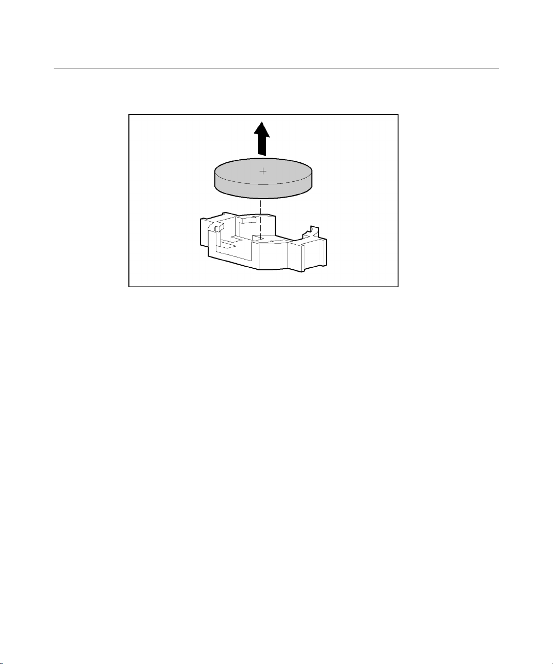
78 HP ProLiant ML310 Generation 2 Server User Guide
5. Remove the battery.
IMPORTANT: Replacing the system board battery resets the system
ROM to its default configuration. After replacing the battery, reconfigure
the system through RBSU.
To replace the component, reverse the removal procedure.
For more information about battery replacement or proper disposal, contact an
authorized reseller or an authorized service provider.
Page 79

79
Troubleshooting
In This Section
Server Diagnostic Steps................................................................................................................79
Important Safety Information .......................................................................................................80
Preparing the Server for Diagnosis...............................................................................................83
Symptom Information...................................................................................................................84
Service Notifications ....................................................................................................................85
Loose Connections .......................................................................................................................85
Diagnostic Steps ...........................................................................................................................85
ROMPaq Disaster Recovery.......................................................................................................101
Manual Recovery........................................................................................................................101
Other Information Resources......................................................................................................102
Server Diagnostic Steps
This section covers the steps to take in order to diagnose a problem quickly.
To effectively troubleshoot a problem, HP recommends that you start with the
first flowchart in this section, "Start Diagnosis Flowchart (on page 86
)," and
follow the appropriate diagnostic path. If the other flowcharts do not provide a
troubleshooting solution, follow the diagnostic steps in "General Diagnosis
Flowchart (on page 88)." The General Diagnosis flowchart is a generic
troubleshooting process to be used when the problem is not server-specific or is
not easily categorized into the other flowcharts.
IMPORTANT: This guide provides information for multiple servers.
Some information may not apply to the server you are troubleshooting.
Refer to the server documentation for information on procedures,
hardware options, software tools, and operating systems supported by
the server.
WARNING: To avoid potential problems, ALWAYS read
the warnings and cautionary information in the server
documentation before removing, replacing, reseating, or modifying
system components.
Page 80

80 HP ProLiant ML310 Generation 2 Server User Guide
Important Safety Information
Familiarize yourself with the safety information in the following sections before
troubleshooting the server.
Important Safety Information
Before servicing this product, read the Important Safety Information document
provided with the server.
Symbols on Equipment
The following symbols may be placed on equipment to indicate the presence of
potentially hazardous conditions.
This symbol indicates the presence of hazardous
energy circuits or electric shock hazards. Refer all servicing to
qualified personnel.
WARNING: To reduce the risk of injury from electric shock
hazards, do not open this enclosure. Refer all maintenance,
upgrades, and servicing to qualified personnel.
This symbol indicates the presence of electric
shock hazards. The area contains no user or field serviceable
parts. Do not open for any reason.
WARNING: To reduce the risk of injury from electric shock
hazards, do not open this enclosure.
This symbol on an RJ-45 receptacle indicates a
network interface connection.
WARNING: To reduce the risk of electric shock, fire, or damage to
the equipment, do not plug telephone or telecommunications
connectors into this receptacle.
Page 81

Troubleshooting 81
This symbol indicates the presence of a hot surface
or hot component. If this surface is contacted, the potential for
injury exists.
WARNING: To reduce the risk of injury from a hot component,
allow the surface to cool before touching.
25-41 kg
55-90 lbs
This symbol indicates that the component exceeds the
recommended weight for one individual to handle safely.
WARNING: To reduce the risk of personal injury or damage to the
equipment, observe local occupational health and safety
requirements and guidelines for manual material handling.
These symbols, on power supplies or
systems, indicate that the equipment is supplied by multiple
sources of power.
WARNING: To reduce the risk of injury from electric shock,
remove all power cords to completely disconnect power from the
system.
Warnings and Cautions
WARNING: Only authorized technicians trained by HP
should attempt to repair this equipment. All troubleshooting and
repair procedures are detailed to allow only subassembly/modulelevel repair. Because of the complexity of the individual boards
and subassemblies, no one should attempt to make repairs at the
component level or to make modifications to any printed wiring
board. Improper repairs can create a safety hazard.
Page 82

82 HP ProLiant ML310 Generation 2 Server User Guide
WARNING: To reduce the risk of personal injury or
damage to the equipment, be sure that:
The leveling feet are extended to the floor. •
•
The full weight of the rack rests on the leveling feet.
•
The stabilizing feet are attached to the rack if it is a single-rack
installation.
•
The racks are coupled together in multiple-rack installations.
•
Only one component is extended at a time. A rack may become
unstable if more than one component is extended for any
reason.
WARNING: To reduce the risk of electric shock or damage
to the equipment:
Do not disable the power cord grounding plug. The grounding
•
plug is an important safety feature.
•
Plug the power cord into a grounded (earthed) electrical outlet
that is easily accessible at all times.
•
Unplug the power cord from the power supply to disconnect
power to the equipment.
•
Do not route the power cord where it can be walked on or
pinched by items placed against it. Pay particular attention to
the plug, electrical outlet, and the point where the cord extends
from the server.
25-41 kg
55-90 lbs
WARNING: To reduce the risk of personal injury or damage to the
equipment:
Page 83

Troubleshooting 83
Observe local occupation health and safety requirements and
•
guidelines for manual handling.
•
Obtain adequate assistance to lift and stabilize the chassis
during installation or removal.
•
The server is unstable when not fastened to the rails.
•
When mounting the server in a rack, remove the power
supplies and any other removable module to reduce the overall
weight of the product.
CAUTION: To properly ventilate the system, you must provide
at least 7.6 cm (3.0 in) of clearance at the front and back of the server.
CAUTION: The server is designed to be electrically grounded
(earthed). To ensure proper operation, plug the AC power cord into a
properly grounded AC outlet only.
Preparing the Server for Diagnosis
1. Be sure the server is in the proper operating environment with adequate
power, air conditioning, and humidity control. Refer to the server
documentation ("Environmental Specifications" on page 113
environmental conditions.
2. Record any error messages displayed by the system.
3. Remove all diskettes and CDs from the media drives.
4. Power down the server and peripheral devices if you will be diagnosing the
server offline. Always perform an orderly shutdown, if possible. This means
you must:
a. Exit any applications.
b. Exit the operating system.
c. Power down the server.
) for required
Page 84

84 HP ProLiant ML310 Generation 2 Server User Guide
5. Disconnect any peripheral devices not required for testing (any devices not
necessary to power up the server). Do not disconnect the printer if you want
to use it to print error messages.
6. Collect all tools and utilities, such as a Torx screwdriver, loopback adapters,
ESD wrist strap, and software utilities, necessary to troubleshoot the
problem.
− You must have the appropriate Health Drivers and Management Agents
installed on the server.
NOTE: To verify the server configuration, connect to the System
Management homepage and select Version Control Agent. The VCA
gives you a list of names and versions of all installed HP drivers,
Management Agents, and utilities, and whether they are up to date.
− HP recommends you have access to the SmartStart CD for value-added
software and drivers required during the troubleshooting process.
− HP recommends you have access to the server documentation
("Environmental Specifications" on page 113
information.
) for server-specific
Symptom Information
Before troubleshooting a server problem, collect the following information:
•
What events preceded the failure? After which steps does the problem occur?
•
What has been changed between the time the server was working and now?
•
Did you recently add or remove hardware or software? If so, did you
remember to change the appropriate settings in the server setup utility, if
necessary?
•
Has the server exhibited problem symptoms for a period of time?
•
If the problem occurs randomly, what is the duration or frequency?
To answer these questions, the following information may be useful:
•
Run HP Insight Diagnostics (on page 73
current configuration or to compare it to previous configurations.
• Refer to your hardware and software records for information.
) and use the survey page to view the
Page 85

Troubleshooting 85
Service Notifications
To find out the latest service notifications, refer to the HP website
(http://www.hp.com/products/servers/platforms
). Select the appropriate server
model, and then click the Documentation link on the product page.
Loose Connections
Action:
•
Be sure all power cords are securely connected.
•
Be sure all cables are properly aligned and securely connected for all external
and internal components.
•
Remove and check all data and power cables for damage. Be sure no cables
have bent pins or damaged connectors.
•
If a fixed cable tray is available for the server, be sure the cords and cables
connected to the server are correctly routed through the tray.
•
Be sure each device is properly seated.
•
If a device has latches, be sure they are completely closed and locked.
•
Check any interlock or interconnect LEDs that may indicate a component is
not connected properly.
•
If problems continue to occur, remove and reinstall each device, checking the
connectors and sockets for bent pins or other damage.
Diagnostic Steps
To effectively troubleshoot a problem, HP recommends that you start with the
first flowchart in this section, "Start Diagnosis Flowchart (on page 86
follow the appropriate diagnostic path. If the other flowcharts do not provide a
troubleshooting solution, follow the diagnostic steps in "General Diagnosis
Flowchart (on page 88
troubleshooting process to be used when the problem is not server-specific or is
not easily categorized into the other flowcharts.
)," and
)." The General Diagnosis flowchart is a generic
Page 86

86 HP ProLiant ML310 Generation 2 Server User Guide
The available flowcharts include:
• Start Diagnosis Flowchart (on page 86
• General Diagnosis Flowchart (on page 88
• Power-On Problems Flowchart (on page 90
• POST Problems Flowchart (on page 93
• OS Boot Problems Flowchart (on page 95
• Server Fault Indications Flowchart (on page 98
The number contained in parentheses in the flowchart boxes corresponds to a
table with references to other detailed documents or troubleshooting instructions.
Start Diagnosis Flowchart
Use the following flowchart to start the diagnostic process.
Item Refer to
1 "General Diagnosis Flowchart (on page 88)"
2 "Power-On Problems Flowchart (on page 90)"
3 "POST Problems Flowchart (on page 93)"
4 "OS Boot Problems Flowchart (on page 95)"
)
)
)
)
)
)
5 "Server Fault Indications Flowchart (on page 98)"
Page 87
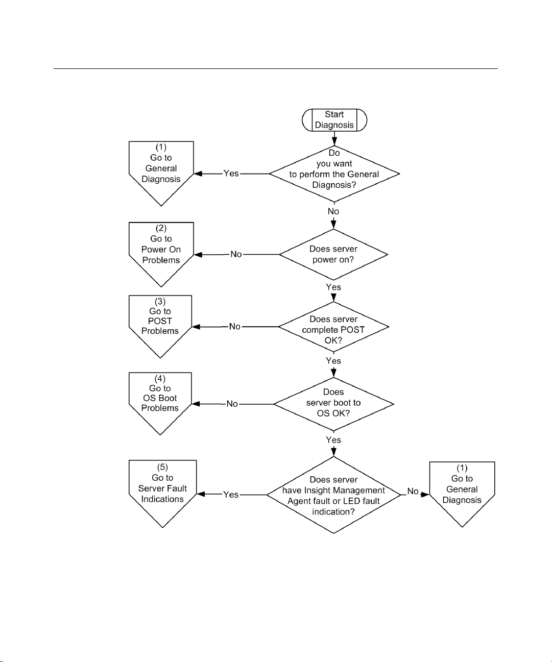
Troubleshooting 87
Page 88
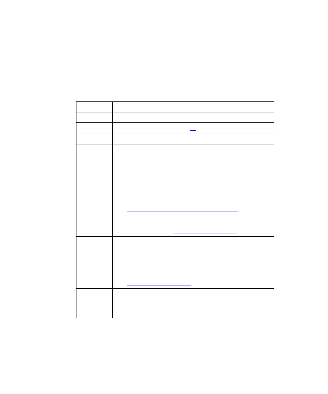
88 HP ProLiant ML310 Generation 2 Server User Guide
General Diagnosis Flowchart
The General Diagnosis flowchart provides a generic approach to troubleshooting.
If you are unsure of the problem, or if the other flowcharts do not fix the
problem, use the following flowchart.
Item Refer to
1 "Symptom Information (on page 84)"
2 "Loose Connections (on page 85)"
3 "Service Notifications (on page 85)"
4 Server maintenance and service guide, located on the
Documentation CD or the HP website
(http://www.hp.com/products/servers/platforms
5 Server user guide or setup and installation guide, located on
the Documentation CD or the HP website
(http://www.hp.com/products/servers/platforms
6 • Server maintenance and service guide, located on the
Documentation CD or the HP website
(http://www.hp.com/products/servers/platforms
• "Hardware Problems" in the HP ProLiant Servers
Troubleshooting Guide located on the Documentation CD or
on the HP website (http://www.hp.com/support
)
)
)
).
7 • "Server Information You Need" in the HP ProLiant Servers
Troubleshooting Guide located on the Documentation CD or
on the HP website (http://www.hp.com/support
• "Operating System Information You Need" in the HP
ProLiant Servers Troubleshooting Guide located on the
Documentation CD or on the HP website
(http://www.hp.com/support).
8 "Contacting HP Technical Support or an Authorized Reseller" in
the HP ProLiant Servers Troubleshooting Guide located on the
Documentation CD or on the HP website
(http://www.hp.com/support
).
).
Page 89

Troubleshooting 89
Page 90

90 HP ProLiant ML310 Generation 2 Server User Guide
Power-On Problems Flowchart
Symptoms:
•
The server does not power on.
•
The system power LED is off or amber.
•
The internal health LED is red or amber.
Possible causes:
•
Improperly seated or faulty power supply
•
Loose or faulty power cord
•
Power supply cord improperly seated to system board
•
Power source problem
•
Power on circuit problem
•
Improperly seated component or interlock problem
•
Faulty internal component
Item Refer to
1 Server user guide or setup and installation guide, located on
the Documentation CD or the HP website
(http://www.hp.com/products/servers/platforms
2 "HP Insight Diagnostics (on page 73)"
3 "Loose Connections (on page 85)"
4 Server maintenance and service guide, located on the
Documentation CD or the HP website
(http://www.hp.com/products/servers/platforms
5 "Integrated Management Log (on page 73)" or in the HP
ProLiant Servers Troubleshooting Guide located on the
Documentation CD or on the HP website
(http://www.hp.com/support
6 "Power Source Problems" in the HP ProLiant Servers
Troubleshooting Guide located on the Documentation CD or on
the HP website (http://www.hp.com/support
).
).
)
).
Page 91

Troubleshooting 91
Item Refer to
7 • "Power Supply Problems" in the HP ProLiant Servers
Troubleshooting Guide located on the Documentation CD or
on the HP website (http://www.hp.com/support
• Server maintenance and service guide, located on the
Documentation CD or the HP website
(http://www.hp.com/products/servers/platforms
8 "System Open Circuits and Short Circuits" in the HP ProLiant
Servers Troubleshooting Guide located on the Documentation
CD or on the HP website (http://www.hp.com/support
).
)
).
Page 92
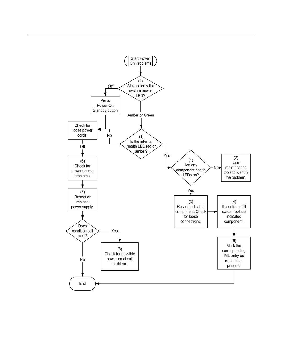
92 HP ProLiant ML310 Generation 2 Server User Guide
Page 93
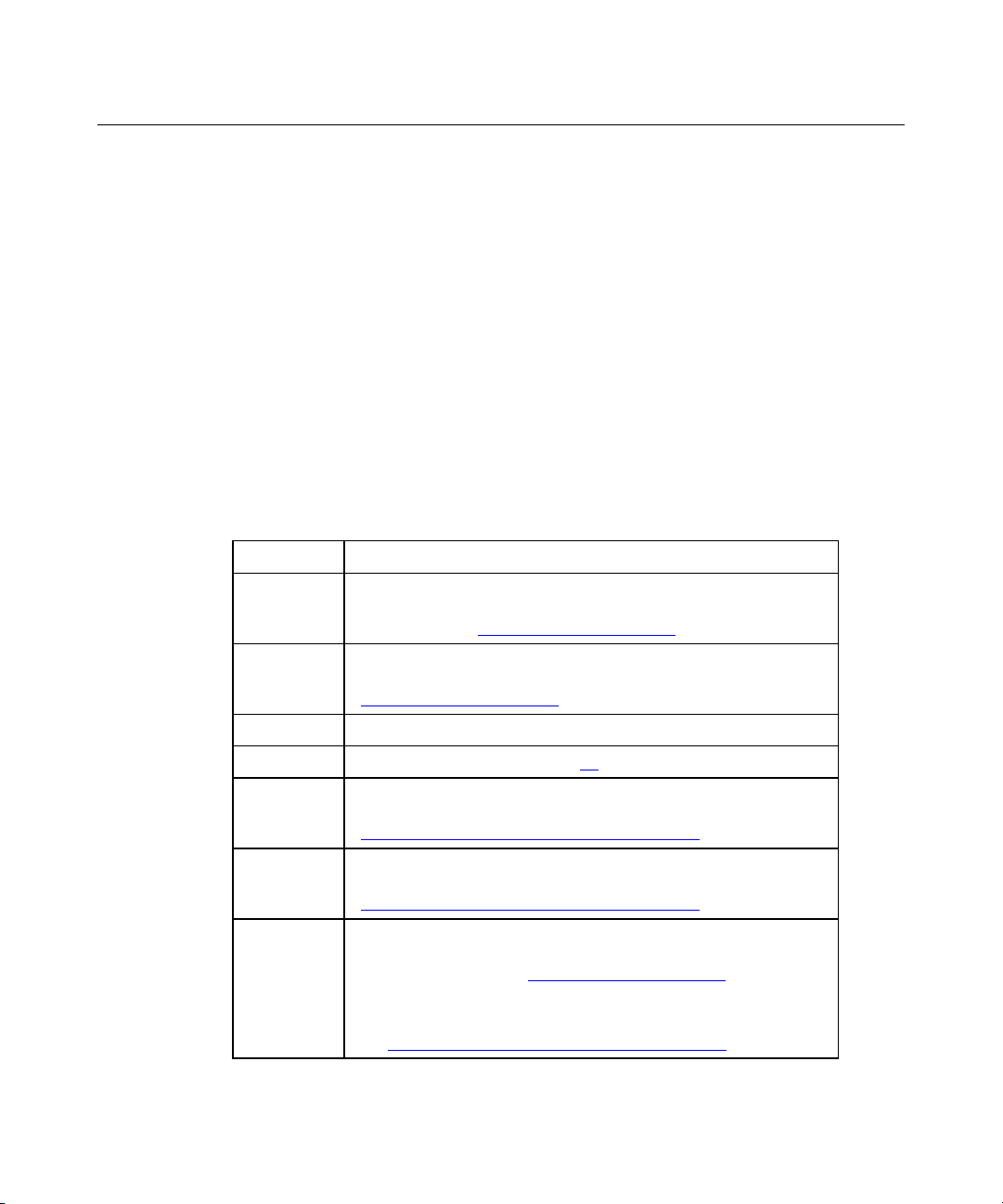
Troubleshooting 93
POST Problems Flowchart
Symptoms:
•
Server does not complete POST
NOTE: The server has completed POST when the system attempts to
access the boot device.
•
Server completes POST with errors
Possible Problems:
•
Improperly seated or faulty internal component
•
Faulty KVM device
•
Faulty video device
Item Refer to
1 "POST Error Messages" in the HP ProLiant Servers
Troubleshooting Guide located on the Documentation CD or on
the HP website (http://www.hp.com/support
).
2 "Video Problems" in the HP ProLiant Servers Troubleshooting
Guide located on the Documentation CD or on the HP website
(http://www.hp.com/support
3 KVM or RILOE documentation
4 "Loose Connections (on page 85)"
5 Server maintenance and service guide, located on the
Documentation CD or the HP website
(http://www.hp.com/products/servers/platforms
6 Server user guide or setup and installation guide, located on
the Documentation CD or the HP website
(http://www.hp.com/products/servers/platforms
7 • "Hardware Problems" in the HP ProLiant Servers
Troubleshooting Guide located on the Documentation CD or
on the HP website (http://www.hp.com/support
• Server maintenance and service guide, located on the
Documentation CD or the HP website
(http://www.hp.com/products/servers/platforms
).
)
)
).
)
Page 94

94 HP ProLiant ML310 Generation 2 Server User Guide
Page 95
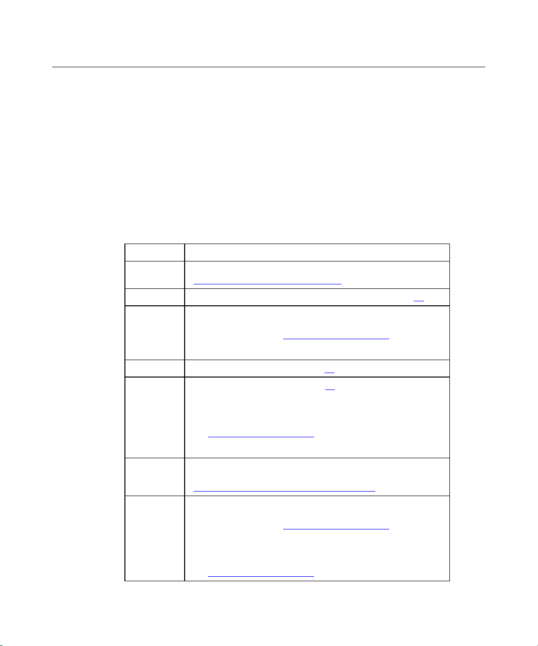
Troubleshooting 95
OS Boot Problems Flowchart
Symptoms:
•
Server does not boot a previously installed operating system
•
Server does not boot SmartStart
Possible Causes:
•
Corrupted operating system
•
Hard drive subsystem problem
Item Refer to
1 HP ROM-Based Setup Utility User Guide
(http://www.hp.com/servers/smartstart)
2 "POST Problems ("POST Problems Flowchart" on page 93)"
3 • "Hard Drive Problems" in the HP ProLiant Servers
Troubleshooting Guide located on the Documentation CD or
on the HP website (http://www.hp.com/support
• Controller documentation
).
4 "HP Insight Diagnostics (on page 73)"
5 • "Loose Connections (on page 85)"
• "CD-ROM and DVD Drive Problems" in the HP ProLiant
Servers Troubleshooting Guide located on the
Documentation CD or on the HP website
(http://www.hp.com/support).
• Controller documentation
6 Server user guide or setup and installation guide, located on
the Documentation CD or the HP website
(http://www.hp.com/products/servers/platforms
7 • "Operating System Problems" in the HP ProLiant Servers
Troubleshooting Guide located on the Documentation CD or
on the HP website (http://www.hp.com/support
• "Contacting HP Technical Support or an Authorized
Reseller" in the HP ProLiant Servers Troubleshooting Guide
located on the Documentation CD or on the HP website
(http://www.hp.com/support
)
).
).
Page 96
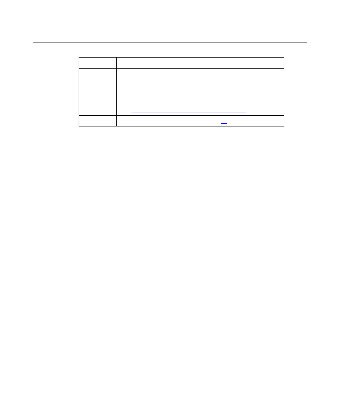
96 HP ProLiant ML310 Generation 2 Server User Guide
Item Refer to
8 • "Hardware Problems" in the HP ProLiant Servers
Troubleshooting Guide located on the Documentation CD or
on the HP website (http://www.hp.com/support
• Server maintenance and service guide, located on the
Documentation CD or the HP website
(http://www.hp.com/products/servers/platforms
9 "General Diagnosis Flowchart (on page 88)"
).
)
Page 97
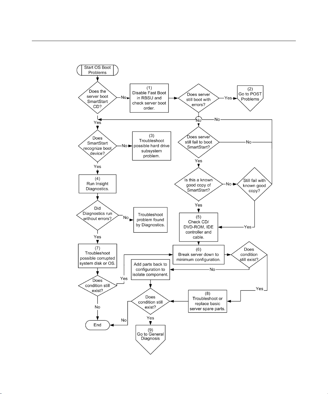
Troubleshooting 97
Page 98

98 HP ProLiant ML310 Generation 2 Server User Guide
Server Fault Indications Flowchart
Symptoms:
• Server boots, but a fault event is reported by Insight Management Agents (on
page 70
•
Server boots, but the internal health LED is red or amber
Possible causes:
•
Improperly seated or faulty internal or external component
•
Unsupported component installed
•
Redundancy failure
•
System overtemperature condition
Item Refer to
1 "Management Agents (on page 70)"
2 • "Integrated Management Log (on page 73)"
)
• "Event List Error Messages" in the HP ProLiant Servers
Troubleshooting Guide located on the Documentation CD or
on the HP website (http://www.hp.com/support
).
3 Server user guide or setup and installation guide, located on
the Documentation CD or the HP website
(http://www.hp.com/products/servers/platforms
4 System Management Homepage
(http://h18013.www1.hp.com/products/servers/management/ag
ents/index.html)
5 "Power-On Problems ("Power-On Problems Flowchart" on page
90
)"
6 • "Hard Drive Problems" in the HP ProLiant Servers
Troubleshooting Guide located on the Documentation CD or
on the HP website (http://www.hp.com/support
• Server maintenance and service guide, located on the
Documentation CD or the HP website
(http://www.hp.com/products/servers/platforms
7 "HP Insight Diagnostics (on page 73)"
)
).
)
Page 99

Troubleshooting 99
Item Refer to
8 • "Hardware Problems" in the HP ProLiant Servers
Troubleshooting Guide located on the Documentation CD or
on the HP website (http://www.hp.com/support
• Server maintenance and service guide, located on the
Documentation CD or the HP website
(http://www.hp.com/products/servers/platforms
).
)
Page 100

100 HP ProLiant ML310 Generation 2 Server User Guide
 Loading...