

Page 1
HP ProLiant ML150
Generation 5 Server
Hard Disk Drive Cage
Overview
This document contains instructions for installing a hot-plug hard disk
drive (HDD) cage in the HP ProLiant ML150 Generation 5 Server.
For more information on preparing the server for installation, refer to
the documentation referenced on the HP ProLiant ML150 Generation
5 Server Support CD.
Installation Instructions
Kit contents
• Hot-plug Hard disk drive (HDD) cage with backplane with four
drive blank panels
• Mounting hardware
• This document
Important safety information
Read the installation instructions completely before beginning the
installation procedure. Refer to the document titled Important Safety
Information on the Support CD.
CAUTION: Electrostatic discharge (ESD) can damage
electronic components. Be sure you are properly
grounded (earthed) before beginning an installation
procedure.
Installation guidelines
This installation is to be performed by qualified personnel who are
knowledgeable of the procedures, precautions, and hazards
associated with equipment containing hazardous energy circuits.
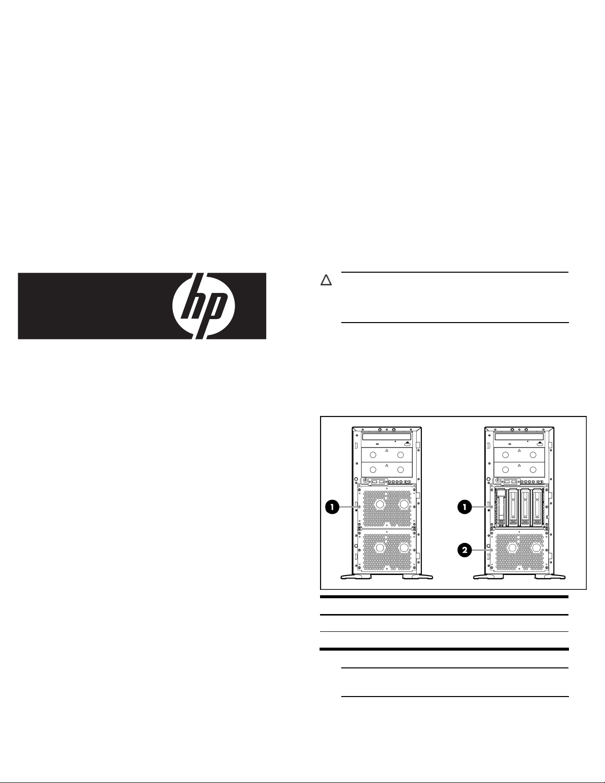
Figure 1 Drive bay areas for servers shipped as non-hot-plug (left)
and hot-plug (right) systems
Legal notices
© Copyright 2007 Hewlett-Packard Development Company, L.P.
The information contained herein is subject to change without notice. The
only warranties for HP products and services are set forth in the express
warranty statements accompanying such products and services. Nothing
herein should be construed as constituting an additional warranty. HP shall
not be liable for technical or editorial errors or omissions contained herein.
Part number 458637-001
October 2007 (First Edition)
Item Description
1 Upper hard drive area (bays 1-4)
2 Lower hard drive area (bays 5-8)
NOTE: Both the upper or lower bay area can support a
hot-plug HDD cage.
Page 2
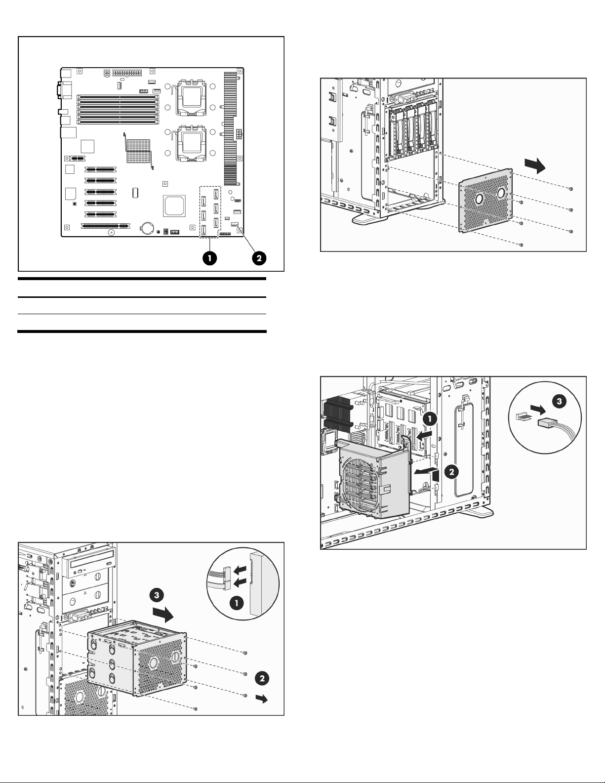
Figure 2 System board connectors
Item Description
1 SATA connectors (6)
2 Front fan connector J35
Installing the HDD cage
1. Shut down the operating system (OS) in an orderly manner.
2. If necessary, press the power button to power down the server.
3. Disconnect the external power cord(s) from the system chassis.
4. If necessary, unlock the chassis.
5. Loosen the thumbscrews and remove the access panel.
6. Remove the front panel bezel.
7. For a server pre-configured as a non-hot-plug system, remove
the existing HDD cage:
a. Disconnect the power and data cables from the drive(s).
b. Remove the six mounting screws.
c. Slide the HDD cage out from the chassis.
8. For a server pre-configured as a hot-plug system, remove the
six mounting screws for the shield covering the lower hard
drive area and remove the shield.
Figure 4 Removing the shield on a hot-plug system
9. If installing the HDD cage into the lower hard drive area,
remove the front fan/PCI card holder assembly as follows:
a. Remove any full-length expansion cards from the server.
b. Press the top tab toward the rear, lift the assembly up
slightly and it rotate away from the lower hard drive area.
c. Lift the assembly away a short distance from the chassis.
d. Disconnect the fan cable from system board connector J35.
and remove the front fan/PCI card holder assembly.
Figure 5 Removing the front fan/PCI card holder assembly
Figure 3 Removing a non-hot-plug HDD
Page 3

10. Install the backplane on the HDD cage:
a. Position the backplane onto the four hooks.
b. Slide the backplane downward to engage the bottom post.
c. Insert and tighten the securing screw.
Figure 6 Installing the backplane to the HDD cage
12. Connect the two power cables to the two 4-pin connectors on
the HDD cage backplane (Figure 8).
13. Connect the data cable from the system board or the
SATA/SAS card to the backplane (Figure 8).
Figure 8 Connecting cables to the backplane of the
hot-plug HDD cage
11. Slide the hot-plug HDD cage into the vacant HDD bay area
and secure with the six mounting screws.
Figure 7 Installing the hot-plug HDD cage
14. If installing the HDD cage into the lower hard drive area,
replace the front fan/PCI card holder assembly as follows:
a. Reconnect the front fan/PCI card holer assembly’s fan
cable to system board connector J35.
b. Insert the tabs of the front fan/PCI card holder assembly to
the holes in the chassis, rotate forward and push down
until it snaps into place.
c. Replace any full-length expansion cards.
15. To install a hot-plug drive:
a. Remove a blank panel from the HDD cage by pressing the
release levers toward each other and pulling the blank
panel out from the HDD cage.
Figure 9 Removing a hot-plug drive blank panel
CAUTION: Blank panels provide proper air flow for a
HDD cage that is not fully populated with hot-plug hard
drives. To avoid thermal conditions that could result in
hardware damage, ensure that all drive bays are
populated with either a blank panel or a hot-plug hard
drive before operating the server.
Page 4

b. With the cam latch rotated up, slide the hot-plug drive into
the vacant bay until resistance is felt (Figure 10).
c. Verify that the hooks on the cam latch will engage the top
ledge of the HDD cage and then rotate the cam latch down
to fully seat the hot-plug drive and press in until it clicks into
place.
Figure 10 Installing a hot-plug hard drive
16. Replace the front bezel.
17. Replace the access panel and tighten the rear thumbscrews.
18. Connect the power cord(s).
Installation is complete.
NOTE: Once the HDD cage is installed, removal and
replacement of hot-plug drives requires only the removal
of the front bezel.
 Loading...