

Page 1

ProLiant ML110 Generation 4 Server
Maintenance and Service Guide
Part number: 419971-002
Second edition: September 2007
Page 2

Legal notices
© Copyright 2007 Hewlett-Packard Development Company, L.P.
The information contained herein is subject to change without notice. The only warranties for HP products and services are set forth in the
express warranty statements accompanying such products and services. Nothing herein should be construed as constituting an additional
warranty. HP shall not be liable for technical or editorial errors or omissions contained herein.
Intel Pentium, Xeon and Celeron are trademarks or registered trademarks of Intel Corporation or its subsidiaries in the United States and
other countries.
Part number: 419971-002
Second edition: September 2007
2
Page 3

Contents
1 Customer self repair
Parts only warranty service........................................................................................................................ 5
2 Illustrated parts catalog
Mechanical Components ........................................................................................................................ 14
System components................................................................................................................................ 17
HP contact information ........................................................................................................................... 19
Before you contact HP ............................................................................................................................ 20
3 Removal and replacement procedures
Hardware configuration tools .................................................................................................................. 21
Hardware configuration information......................................................................................................... 21
Non-hot-plug device .......................................................................................................................... 21
Electrostatic discharge information ...................................................................................................... 21
Symbols on equipment....................................................................................................................... 21
Pre-installation instructions .................................................................................................................. 22
Post-installation instructions................................................................................................................. 22
Powering down the server....................................................................................................................... 23
System covers........................................................................................................................................ 23
Access panel.................................................................................................................................... 23
Front bezel....................................................................................................................................... 24
Drives................................................................................................................................................... 25
Cable management........................................................................................................................... 25
Cable connections ............................................................................................................................ 26
Drive bay configuration ..................................................................................................................... 26
Releasing drives................................................................................................................................ 27
Optical drive.................................................................................................................................... 27
Optional media device ...................................................................................................................... 28
Hard drives...................................................................................................................................... 29
Drive latch ....................................................................................................................................... 31
System board components ...................................................................................................................... 32
Processor ......................................................................................................................................... 32
Memory........................................................................................................................................... 35
Expansion cards ............................................................................................................................... 36
System battery .................................................................................................................................. 41
Power supply unit (PSU) .......................................................................................................................... 42
System fan ............................................................................................................................................ 43
Install IPMI Card .................................................................................................................................... 45
4 Diagnostic tools and Setup Utilities
BIOS Software....................................................................................................................................... 46
BIOS Setup Utility .................................................................................................................................. 46
Accessing the BIOS Setup Utility .............................................................................................................. 46
Navigating through the Setup Utility .................................................................................................... 46
Setup Utility Menu Bar ....................................................................................................................... 48
BIOS Update......................................................................................................................................... 53
Clear CMOS......................................................................................................................................... 53
Power-On Self-Test (POST)....................................................................................................................... 54
POST Error Indicators ........................................................................................................................ 54
Recoverable POST Errors ................................................................................................................... 54
POST Related Troubleshooting ............................................................................................................ 55
5 Connectors, switches and LEDs
Connectors and components ................................................................................................................... 56
Front panel components..................................................................................................................... 56
Contents 3
Page 4

Rear panel components ..................................................................................................................... 56
System board components.................................................................................................................. 57
Jumpers – Password and Boot Block .................................................................................................... 58
Clear CMOS button .......................................................................................................................... 58
Status LED indicators .............................................................................................................................. 58
Front panel LED indicators.................................................................................................................. 58
Rear panel LED indicators .................................................................................................................. 60
System board LED indicators .............................................................................................................. 60
6 Physical and operating specifications
System unit............................................................................................................................................ 62
Memory................................................................................................................................................ 64
Processor.............................................................................................................................................. 64
IDE CD-ROM drive ................................................................................................................................. 65
SAS hard drive...................................................................................................................................... 66
SATA hard drive.................................................................................................................................... 66
SAS storage controller ............................................................................................................................ 67
Index
Contents 4
Page 5

1 Customer self repair
HP products are designed with many Customer Self Repair (CSR) parts to minimize repair time and
allow for greater flexibility in performing defective parts replacement. If during the diagnosis period
HP (or HP service providers or service partners) identifies that the repair can be accomplished by the
use of a CSR part, HP will ship that part directly to you for replacement. There are two categories of
CSR parts:
• Mandatory – Parts for which customer self repair is mandatory. If you request HP to replace these parts, you
will be charged for the travel and labor costs of this service.
• Optional – Parts for which customer self repair is optional. These parts are also designed for customer self
repair. If, however, you require that HP replace them for you, there may or may not be additional charges,
depending on the type of warranty service designated for your product.
NOTE: Some HP parts are not designed for customer self repair. In order to satisfy the customer
warranty, HP requires that an authorized service provider replace the part. These parts are identified
as "No" in the Illustrated Parts Catalog.
Based on availability and where geography permits, CSR parts will be shipped for next business day
delivery. Same day or four-hour delivery may be offered at an additional charge where geography
permits. If assistance is required, you can call the HP Technical Support Center and a technician will
help you over the telephone. HP specifies in the materials shipped with a replacement CSR part
whether a defective part must be returned to HP. In cases where it is required to return the defective
part to HP, you must ship the defective part back to HP within a defined period of time, normally five
(5) business days. The defective part must be returned with the associated documentation in the
provided shipping material. Failure to return the defective part may result in HP billing you for the
replacement. With a customer self repair, HP will pay all shipping and part return costs and
determine the courier/carrier to be used.
For more information about HP's Customer Self Repair program, contact your local service provider.
For the North American program, refer to the HP website (
http://www.hp.com/go/selfrepair).
Parts only warranty service
Your HP Limited Warranty may include a parts only warranty service. Under the terms of parts only
warranty service, HP will provide replacement parts free of charge.
For parts only warranty service, CSR part replacement is mandatory. If you request HP to replace
these parts, you will be charged for the travel and labor costs of this service.
Réparation par le client (CSR)
Les produits HP comportent de nombreuses pièces CSR (Customer Self Repair = réparation par le
client) afin de minimiser les délais de réparation et faciliter le remplacement des pièces défectueuses.
Si pendant la période de diagnostic, HP (ou ses partenaires ou mainteneurs agréés) détermine que la
réparation peut être effectuée à l'aide d'une pièce CSR, HP vous l'envoie directement. Il existe deux
catégories de pièces CSR:
• Obligatoire – Pièces pour lesquelles la réparation par le client est obligatoire. Si vous demandez à HP de
remplacer ces pièces, les coûts de déplacement et main d'œuvre du service vous seront facturés.
• Facultatif – Pièces pour lesquelles la réparation par le client est facultative. Ces pièces sont également
conçues pour permettre au client d'effectuer lui-même la réparation. Toutefois, si vous demandez à HP de
remplacer ces pièces, l'intervention peut ou non vous être facturée, selon le type de garantie applicable à
votre produit.
REMARQUE: Certaines pièces HP ne sont pas conçues pour permettre au client d'effectuer lui-même
la réparation. Pour que la garantie puisse s'appliquer, HP exige que le remplacement de la pièce soit
effectué par un Mainteneur Agréé. Ces pièces sont identifiées par la mention "Non" dans le
Catalogue illustré.
Customer self repair 5
Page 6

Les pièces CSR sont livrées le jour ouvré suivant, dans la limite des stocks disponibles et selon votre
situation géographique. Si votre situation géographique le permet et que vous demandez une
livraison le jour même ou dans les 4 heures, celle-ci vous sera facturée. Pour bénéficier d'une
assistance téléphonique, appelez le Centre d'assistance technique HP. Dans les documents envoyés
avec la pièce de rechange CSR, HP précise s'il est nécessaire de lui retourner la pièce défectueuse. Si
c'est le cas, vous devez le faire dans le délai indiqué, généralement cinq (5) jours ouvrés. La pièce et
sa documentation doivent être retournées dans l'emballage fourni. Si vous ne retournez pas la pièce
défectueuse, HP se réserve le droit de vous facturer les coûts de remplacement. Dans le cas d'une
pièce CSR, HP supporte l'ensemble des frais d'expédition et de retour, et détermine la société de
courses ou le transporteur à utiliser.
Pour plus d'informations sur le programme CSR de HP, contactez votre Mainteneur Agrée local. Pour
plus d'informations sur ce programme en Amérique du Nord, consultez le site Web HP
(
http://www.hp.com/go/selfrepair).
Service de garantie "pièces seules"
Votre garantie limitée HP peut inclure un service de garantie "pièces seules". Dans ce cas, les pièces
de rechange fournies par HP ne sont pas facturées.
Dans le cadre de ce service, la réparation des pièces CSR par le client est obligatoire. Si vous
demandez à HP de remplacer ces pièces, les coûts de déplacement et main d'œuvre du service vous
seront facturés.
Riparazione da parte del cliente
Per abbreviare i tempi di riparazione e garantire una maggiore flessibilità nella sostituzione di parti
difettose, i prodotti HP sono realizzati con numerosi componenti che possono essere riparati
direttamente dal cliente (CSR, Customer Self Repair). Se in fase di diagnostica HP (o un centro di
servizi o di assistenza HP) identifica il guasto come riparabile mediante un ricambio CSR, HP lo
spedirà direttamente al cliente per la sostituzione. Vi sono due categorie di parti CSR:
• Obbligatorie – Parti che devono essere necessariamente riparate dal cliente. Se il cliente ne affida la
riparazione ad HP, deve sostenere le spese di spedizione e di manodopera per il servizio.
• Opzionali – Parti la cui riparazione da parte del cliente è facoltativa. Si tratta comunque di componenti
progettati per questo scopo. Se tuttavia il cliente ne richiede la sostituzione ad HP, potrebbe dover
sostenere spese addizionali a seconda del tipo di garanzia previsto per il prodotto.
NOTA: alcuni componenti HP non sono progettati per la riparazione da parte del cliente. Per
rispettare la garanzia, HP richiede che queste parti siano sostituite da un centro di assistenza
autorizzato. Tali parti sono identificate da un "No" nel Catalogo illustrato dei componenti.
In base alla disponibilità e alla località geografica, le parti CSR vengono spedite con consegna entro
il giorno lavorativo seguente. La consegna nel giorno stesso o entro quattro ore è offerta con un
supplemento di costo solo in alcune zone. In caso di necessità si può richiedere l'assistenza telefonica
di un addetto del centro di supporto tecnico HP. Nel materiale fornito con una parte di ricambio CSR,
HP specifica se il cliente deve restituire dei componenti. Qualora sia richiesta la resa ad HP del
componente difettoso, lo si deve spedire ad HP entro un determinato periodo di tempo, generalmente
cinque (5) giorni lavorativi. Il componente difettoso deve essere restituito con la documentazione
associata nell'imballo di spedizione fornito. La mancata restituzione del componente può comportare
la fatturazione del ricambio da parte di HP. Nel caso di riparazione da parte del cliente, HP sostiene
tutte le spese di spedizione e resa e sceglie il corriere/vettore da utilizzare.
Per ulteriori informazioni sul programma CSR di HP contattare il centro di assistenza di zona. Per il
programma in Nord America fare riferimento al sito Web HP (
http://www.hp.com/go/selfrepair).
Customer self repair 6
Page 7

Servizio di garanzia per i soli componenti
La garanzia limitata HP può includere un servizio di garanzia per i soli componenti. Nei termini di
garanzia del servizio per i soli componenti, HP fornirà gratuitamente le parti di ricambio.
Per il servizio di garanzia per i soli componenti è obbligatoria la formula CSR che prevede la
riparazione da parte del cliente. Se il cliente invece richiede la sostituzione ad HP, dovrà sostenere le
spese di spedizione e di manodopera per il servizio.
Customer Self Repair
HP Produkte enthalten viele CSR-Teile (Customer Self Repair), um Reparaturzeiten zu minimieren und
höhere Flexibilität beim Austausch defekter Bauteile zu ermöglichen. Wenn HP (oder ein HP
Servicepartner) bei der Diagnose feststellt, dass das Produkt mithilfe eines CSR-Teils repariert werden
kann, sendet Ihnen HP dieses Bauteil zum Austausch direkt zu. CSR-Teile werden in zwei Kategorien
unterteilt:
• Zwingend – Teile, für die das Customer Self Repair-Verfahren zwingend vorgegeben ist. Wenn Sie den
Austausch dieser Teile von HP vornehmen lassen, werden Ihnen die Anfahrt- und Arbeitskosten für diesen
Service berechnet.
• Optional – Teile, für die das Customer Self Repair-Verfahren optional ist. Diese Teile sind auch für Customer
Self Repair ausgelegt. Wenn Sie jedoch den Austausch dieser Teile von HP vornehmen lassen möchten,
können bei diesem Service je nach den für Ihr Produkt vorgesehenen Garantiebedingungen zusätzliche
Kosten anfallen.
HINWEIS: Einige Teile sind nicht für Customer Self Repair ausgelegt. Um den Garantieanspruch des
Kunden zu erfüllen, muss das Teil von einem HP Servicepartner ersetzt werden. Im illustrierten
Teilekatalog sind diese Teile mit „No“ bzw. „Nein“ gekennzeichnet.
CSR-Teile werden abhängig von der Verfügbarkeit und vom Lieferziel am folgenden Geschäftstag
geliefert. Für bestimmte Standorte ist eine Lieferung am selben Tag oder innerhalb von vier Stunden
gegen einen Aufpreis verfügbar. Wenn Sie Hilfe benötigen, können Sie das HP technische Support
Center anrufen und sich von einem Mitarbeiter per Telefon helfen lassen. Den Materialien, die mit
einem CSR-Ersatzteil geliefert werden, können Sie entnehmen, ob das defekte Teil an HP
zurückgeschickt werden muss. Wenn es erforderlich ist, das defekte Teil an HP zurückzuschicken,
müssen Sie dies innerhalb eines vorgegebenen Zeitraums tun, in der Regel innerhalb von fünf (5)
Geschäftstagen. Das defekte Teil muss mit der zugehörigen Dokumentation in der Verpackung
zurückgeschickt werden, die im Lieferumfang enthalten ist. Wenn Sie das defekte Teil nicht
zurückschicken, kann HP Ihnen das Ersatzteil in Rechnung stellen. Im Falle von Customer Self Repair
kommt HP für alle Kosten für die Lieferung und Rücksendung auf und bestimmt den Kurier/Frachtdienst.
Weitere Informationen über das HP Customer Self Repair Programm erhalten Sie von Ihrem
Servicepartner vor Ort. Informationen über das CSR-Programm in Nordamerika finden Sie auf der HP
Website unter (
http://www.hp.com/go/selfrepair).
Parts-only Warranty Service (Garantieservice
ausschließlich für Teile)
Ihre HP Garantie umfasst möglicherweise einen Parts-only Warranty Service (Garantieservice
ausschließlich für Teile). Gemäß den Bestimmungen des Parts-only Warranty Service stellt HP
Ersatzteile kostenlos zur Verfügung.
Für den Parts-only Warranty Service ist das CSR-Verfahren zwingend vorgegeben. Wenn Sie den
Austausch dieser Teile von HP vornehmen lassen, werden Ihnen die Anfahrt- und Arbeitskosten für
diesen Service berechnet.
Customer self repair 7
Page 8

Reparaciones del propio cliente
Los productos de HP incluyen muchos componentes que el propio usuario puede reemplazar
(Customer Self Repair, CSR) para minimizar el tiempo de reparación y ofrecer una mayor flexibilidad
a la hora de realizar sustituciones de componentes defectuosos. Si, durante la fase de diagnóstico,
HP (o los proveedores o socios de servicio de HP) identifica que una reparación puede llevarse a
cabo mediante el uso de un componente CSR, HP le enviará dicho componente directamente para
que realice su sustitución. Los componentes CSR se clasifican en dos categorías:
• Obligatorio – componentes para los que la reparación por parte del usuario es obligatoria. Si solicita a HP
que realice la sustitución de estos componentes, tendrá que hacerse cargo de los gastos de
desplazamiento y de mano de obra de dicho servicio.
• Opcional – componentes para los que la reparación por parte del usuario es opcional. Estos componentes
también están diseñados para que puedan ser reparados por el usuario. Sin embargo, si precisa que HP
realice su sustitución, puede o no conllevar costes adicionales, dependiendo del tipo de servicio de
garantía correspondiente al producto.
NOTA: Algunos componentes no están diseñados para que puedan ser reparados por el usuario.
Para que el usuario haga valer su garantía, HP pone como condición que un proveedor de servicios
autorizado realice la sustitución de estos componentes. Dichos componentes se identifican con la
palabra "No" en el catálogo ilustrado de componentes.
Según la disponibilidad y la situación geográfica, los componentes CSR se enviarán para que
lleguen a su destino al siguiente día laborable. Si la situación geográfica lo permite, se puede
solicitar la entrega en el mismo día o en cuatro horas con un coste adicional. Si precisa asistencia
técnica, puede llamar al Centro de asistencia técnica de HP y recibirá ayuda telefónica por parte de
un técnico. Con el envío de materiales para la sustitución de componentes CSR, HP especificará si los
componentes defectuosos deberán devolverse a HP. En aquellos casos en los que sea necesario
devolver algún componente a HP, deberá hacerlo en el periodo de tiempo especificado,
normalmente cinco días laborables. Los componentes defectuosos deberán devolverse con toda la
documentación relacionada y con el embalaje de envío. Si no enviara el componente defectuoso
requerido, HP podrá cobrarle por el de sustitución. En el caso de todas sustituciones que lleve a cabo
el cliente, HP se hará cargo de todos los gastos de envío y devolución de componentes y escogerá la
empresa de transporte que se utilice para dicho servicio.
Para obtener más información acerca del programa de Reparaciones del propio cliente de HP,
póngase en contacto con su proveedor de servicios local. Si está interesado en el programa para
Norteamérica, visite la página web de HP siguiente (
http://www.hp.com/go/selfrepair).
Servicio de garantía exclusivo de componentes
La garantía limitada de HP puede que incluya un servicio de garantía exclusivo de componentes.
Según las condiciones de este servicio exclusivo de componentes, HP le facilitará los componentes de
repuesto sin cargo adicional alguno.
Para este servicio de garantía exclusivo de componentes, es obligatoria la sustitución de
componentes por parte del usuario (CSR). Si solicita a HP que realice la sustitución de estos
componentes, tendrá que hacerse cargo de los gastos de desplazamiento y de mano de obra de
dicho servicio.
Customer Self Repair
Veel onderdelen in HP producten zijn door de klant zelf te repareren, waardoor de reparatieduur tot
een minimum beperkt kan blijven en de flexibiliteit in het vervangen van defecte onderdelen groter is.
Deze onderdelen worden CSR-onderdelen (Customer Self Repair) genoemd. Als HP (of een HP
Service Partner) bij de diagnose vaststelt dat de reparatie kan worden uitgevoerd met een CSR-
Customer self repair 8
Page 9

onderdeel, verzendt HP dat onderdeel rechtstreeks naar u, zodat u het defecte onderdeel daarmee
kunt vervangen. Er zijn twee categorieën CSR-onderdelen:
• Verplicht – Onderdelen waarvoor reparatie door de klant verplicht is. Als u HP verzoekt deze onderdelen
voor u te vervangen, worden u voor deze service reiskosten en arbeidsloon in rekening gebracht.
• Optioneel – Onderdelen waarvoor reparatie door de klant optioneel is. Ook deze onderdelen zijn
ontworpen voor reparatie door de klant. Als u echter HP verzoekt deze onderdelen voor u te vervangen,
kunnen daarvoor extra kosten in rekening worden gebracht, afhankelijk van het type garantieservice voor
het product.
OPMERKING: Sommige HP onderdelen zijn niet ontwikkeld voor reparatie door de klant. In verband
met de garantievoorwaarden moet het onderdeel door een geautoriseerde Service Partner worden
vervangen. Deze onderdelen worden in de geïllustreerde onderdelencatalogus aangemerkt met
"Nee".
Afhankelijk van de leverbaarheid en de locatie worden CSR-onderdelen verzonden voor levering op
de eerstvolgende werkdag. Levering op dezelfde dag of binnen vier uur kan tegen meerkosten
worden aangeboden, indien dit mogelijk is gezien de locatie. Indien assistentie gewenst is, belt u een
HP Service Partner om via de telefoon technische ondersteuning te ontvangen. HP vermeldt in de
documentatie bij het vervangende CSR-onderdeel of het defecte onderdeel aan HP moet worden
geretourneerd. Als het defecte onderdeel aan HP moet worden teruggezonden, moet u het defecte
onderdeel binnen een bepaalde periode, gewoonlijk vijf (5) werkdagen, retourneren aan HP. Het
defecte onderdeel moet met de bijbehorende documentatie worden geretourneerd in het
meegeleverde verpakkingsmateriaal. Als u het defecte onderdeel niet terugzendt, kan HP u voor het
vervangende onderdeel kosten in rekening brengen. Bij reparatie door de klant betaalt HP alle
verzendkosten voor het vervangende en geretourneerde onderdeel en kiest HP zelf welke
koerier/transportonderneming hiervoor wordt gebruikt.
Neem contact op met een Service Partner voor meer informatie over het Customer Self Repair
programma van HP. Informatie over Service Partners vindt u op de HP website
(
http://www.hp.nl/services/servicepartners).
Garantieservice "Parts Only"
Het is mogelijk dat de HP garantie alleen de garantieservice "Parts Only" omvat. Volgens de
bepalingen van de Parts Only garantieservice zal HP kosteloos vervangende onderdelen ter
beschikking stellen.
Voor de Parts Only garantieservice is vervanging door CSR-onderdelen verplicht. Als u HP verzoekt
deze onderdelen voor u te vervangen, worden u voor deze service reiskosten en arbeidsloon in
rekening gebracht.
Reparo feito pelo cliente
Os produtos da HP são projetados com muitas peças para reparo feito pelo cliente (CSR) de modo a
minimizar o tempo de reparo e permitir maior flexibilidade na substituição de peças com defeito. Se,
durante o período de diagnóstico, a HP (ou fornecedores/parceiros de serviço da HP) concluir que o
reparo pode ser efetuado pelo uso de uma peça CSR, a peça de reposição será enviada diretamente
ao cliente. Existem duas categorias de peças CSR:
• Obrigatória – Peças cujo reparo feito pelo cliente é obrigatório. Se desejar que a HP substitua essas
peças, serão cobradas as despesas de transporte e mão-de-obra do serviço.
• Opcional – Peças cujo reparo feito pelo cliente é opcional. Essas peças também são projetadas para o
reparo feito pelo cliente. No entanto, se desejar que a HP as substitua, pode haver ou não a cobrança de
taxa adicional, dependendo do tipo de serviço de garantia destinado ao produto.
OBSERVAÇÃO: Algumas peças da HP não são projetadas para o reparo feito pelo cliente. A fim de
cumprir a garantia do cliente, a HP exige que um técnico autorizado substitua a peça. Essas peças
estão identificadas com a marca "No" (Não), no catálogo de peças ilustrado.
Customer self repair 9
Page 10
Conforme a disponibilidade e o local geográfico, as peças CSR serão enviadas no primeiro dia útil
após o pedido. Onde as condições geográficas permitirem, a entrega no mesmo dia ou em quatro
horas pode ser feita mediante uma taxa adicional. Se precisar de auxílio, entre em contato com o
Centro de suporte técnico da HP para que um técnico o ajude por telefone. A HP especifica nos
materiais fornecidos com a peça CSR de reposição se a peça com defeito deve ser devolvida à HP.
Nos casos em que isso for necessário, é preciso enviar a peça com defeito à HP dentro do período
determinado, normalmente cinco (5) dias úteis. A peça com defeito deve ser enviada com a
documentação correspondente no material de transporte fornecido. Caso não o faça, a HP poderá
cobrar a reposição. Para as peças de reparo feito pelo cliente, a HP paga todas as despesas de
transporte e de devolução da peça e determina a transportadora/serviço postal a ser utilizado.
Para obter mais informações sobre o programa de reparo feito pelo cliente da HP, entre em contato
com o fornecedor de serviços local. Para o programa norte-americano, visite o site da HP
(
http://www.hp.com/go/selfrepair).
Serviço de garantia apenas para peças
A garantia limitada da HP pode incluir um serviço de garantia apenas para peças. Segundo os
termos do serviço de garantia apenas para peças, a HP fornece as peças de reposição sem cobrar
nenhuma taxa.
No caso desse serviço, a substituição de peças CSR é obrigatória. Se desejar que a HP substitua
essas peças, serão cobradas as despesas de transporte e mão-de-obra do serviço.
Customer self repair 10
Page 11
Customer self repair 11
Page 12
Customer self repair 12
Page 13
Customer self repair 13
Page 14
2 Illustrated parts catalog
This chapter provides the illustrated parts breakdown and spare parts lists for the HP ProLiant ML110 Generation
4 server. Information for contacting HP is also provided.
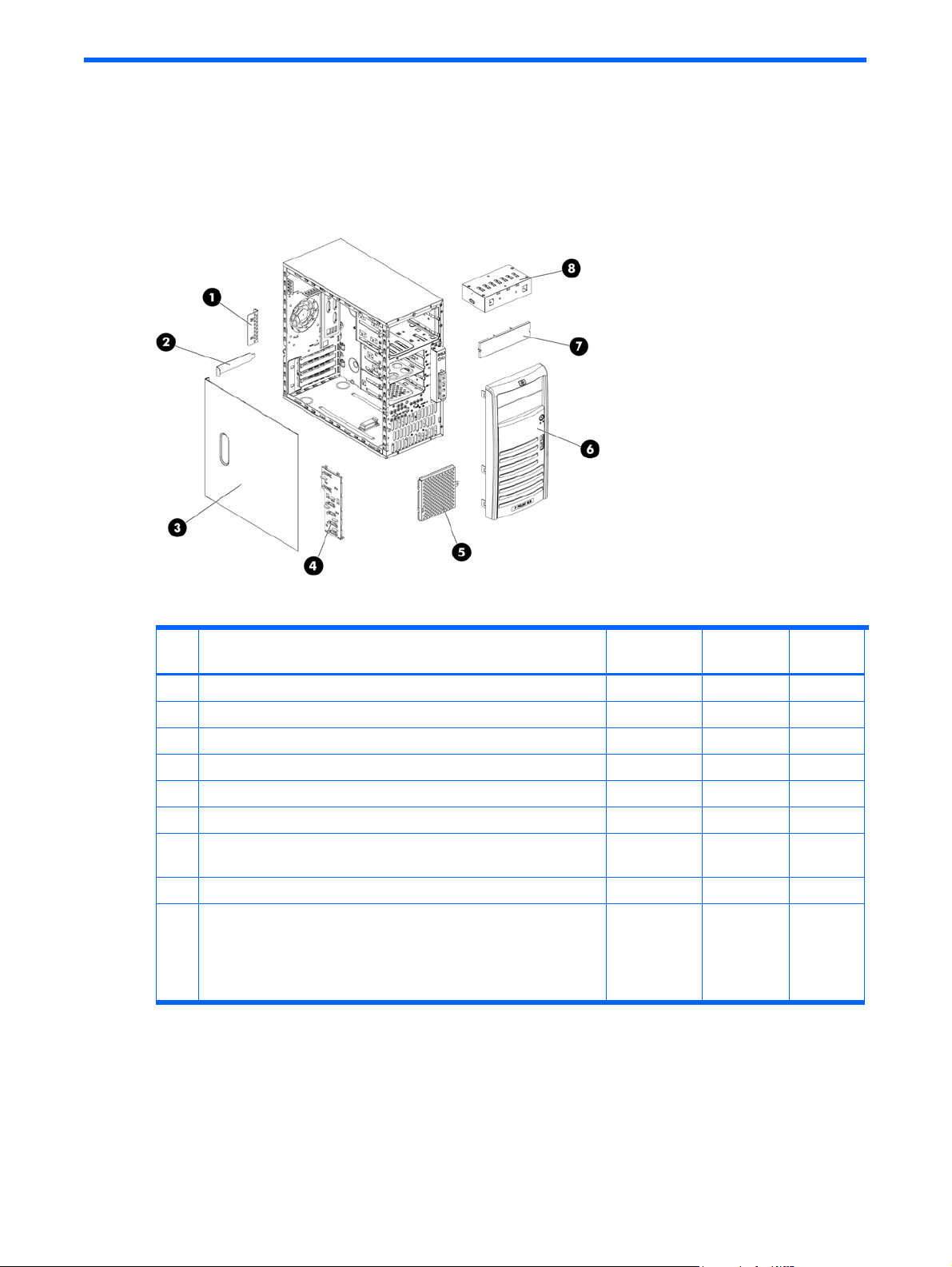
Mechanical Components
Figure 2-1 Mechanical Components
Table 2-1 Mechanical spare parts list
Item Description
1 Expansion slot cover lock 397084-001 433557-001 Mandatory
2 IPMI card bracket dummy 434032-001 433557-001 Mandatory
3 Access panel 437973-001 440223-001 Mandatory
4 Drive release latch 434031-001 433557-001 Mandatory
5 Hard drive EMI shield 430277-001 430412-001 Mandatory
6 Front bezel 391980-001 392174-001 Mandatory
7 Blank bezel 166775-004 335937-001
8 Drive shield 395019-001 395625-001 Mandatory
9 Misc Plastics/Hardware Kit*, including:
• Screw, 6-32x.187, TF, HI/TP w/serr
• Screw, M3, TT, HI/TP, S151PX5mm
• Feet
• Thumbscrew, 6-32X.25,Cbn
*Not shown
1
Mandatory—Parts for which customer self repair is mandatory. If you request HP to replace these parts, you will be charged
for the travel and labor costs of this service.
2
Optional—Parts for which customer self repair is optional. These parts are also designed for customer self repair. If, however,
you require that HP replace them for you, there may or may not be additional charges, depending on the type of warranty
service designated for your product.
3
No—Some HP parts are not designed for customer self repair. In order to satisfy the customer warranty, HP requires that an
authorized service provider replace the part. These parts are identified as "No" in the Illustrated Parts Catalog.
Assembly
number
192308-003
247348-001
166939-007
124702-004
Spare part
number
335937-005
397119-001
Customer
self repair
Mandatory
Mandatory
1
1
1
1
1
1
1
1
1
Illustrated parts catalog 14
Page 15

1
Mandatory: Obligatoire—Pièces pour lesquelles la réparation par le client est obligatoire. Si vous demandez à HP de
remplacer ces pièces, les coûts de déplacement et main d'œuvre du service vous seront facturés.
2
Optional: Facultatif—Pièces pour lesquelles la réparation par le client est facultative. Ces pièces sont également conçues pour
permettre au client d'effectuer lui-même la réparation. Toutefois, si vous demandez à HP de remplacer ces pièces, l'intervention
peut ou non vous être facturée, selon le type de garantie applicable à votre produit.
3
No: Non—Certaines pièces HP ne sont pas conçues pour permettre au client d'effectuer lui-même la réparation. Pour que la
garantie puisse s'appliquer, HP exige que le remplacement de la pièce soit effectué par un Mainteneur Agréé. Ces pièces sont
identifiées par la mention “Non” dans le Catalogue illustré.
1
Mandatory: Obbligatorie—Parti che devono essere necessariamente riparate dal cliente. Se il cliente ne affida la riparazione
ad HP, deve sostenere le spese di spedizione e di manodopera per il servizio.
2
Optional: Opzionali—Parti la cui riparazione da parte del cliente è facoltativa. Si tratta comunque di componenti progettati
per questo scopo. Se tuttavia il cliente ne richiede la sostituzione ad HP, potrebbe dover sostenere spese addizionali a
seconda del tipo di garanzia previsto per il prodotto.
3
No: Non CSR—Alcuni componenti HP non sono progettati per la riparazione da parte del cliente. Per rispettare la garanzia,
HP richiede che queste parti siano sostituite da un centro di assistenza autorizzato. Tali parti sono identificate da un “No” nel
Catalogo illustrato dei componenti.
1
Mandatory: Zwingend—Teile, die im Rahmen des Customer Self Repair Programms ersetzt werden müssen. Wenn Sie diese
Teile von HP ersetzen lassen, werden Ihnen die Versand- und Arbeitskosten für diesen Service berechnet.
2
Optional: Optional—Teile, für die das Customer Self Repair-Verfahren optional ist. Diese Teile sind auch für Customer Self
Repair ausgelegt. Wenn Sie jedoch den Austausch dieser Teile von HP vornehmen lassen möchten, können bei diesem Service
je nach den für Ihr Produkt vorgesehenen Garantiebedingungen zusätzliche Kosten anfallen.
3
No: Kein—Einige Teile sind nicht für Customer Self Repair ausgelegt. Um den Garantieanspruch des Kunden zu erfüllen, muss
das Teil von einem HP Servicepartner ersetzt werden. Im illustrierten Teilekatalog sind diese Teile mit „No“ bzw. „Nein“
gekennzeichnet.
1
Mandatory: Obligatorio—componentes para los que la reparación por parte del usuario es obligatoria. Si solicita a HP que
realice la sustitución de estos componentes, tendrá que hacerse cargo de los gastos de desplazamiento y de mano de obra de
dicho servicio.
2
Optional: Opcional— componentes para los que la reparación por parte del usuario es opcional. Estos componentes
también están diseñados para que puedan ser reparados por el usuario. Sin embargo, si precisa que HP realice su
sustitución, puede o no conllevar costes adicionales, dependiendo del tipo de servicio de garantía correspondiente al
producto.
3
No: No—Algunos componentes no están diseñados para que puedan ser reparados por el usuario. Para que el usuario
haga valer su garantía, HP pone como condición que un proveedor de servicios autorizado realice la sustitución de estos
componentes. Dichos componentes se identifican con la palabra “No” en el catálogo ilustrado de componentes.
1
Mandatory: Verplicht—Onderdelen waarvoor Customer Self Repair verplicht is. Als u HP verzoekt deze onderdelen te
vervangen, komen de reiskosten en het arbeidsloon voor uw rekening.
2
Optional: Optioneel—Onderdelen waarvoor reparatie door de klant optioneel is. Ook deze onderdelen zijn ontworpen voor
reparatie door de klant. Als u echter HP verzoekt deze onderdelen voor u te vervangen, kunnen daarvoor extra kosten in
rekening worden gebracht, afhankelijk van het type garantieservice voor het product.
3
No: Nee—Sommige HP onderdelen zijn niet ontwikkeld voor reparatie door de klant. In verband met de
garantievoorwaarden moet het onderdeel door een geautoriseerde Service Partner worden vervangen. Deze onderdelen
worden in de geïllustreerde onderdelencatalogus aangemerkt met "Nee".
1
Mandatory: Obrigatória—Peças cujo reparo feito pelo cliente é obrigatório. Se desejar que a HP substitua essas peças,
serão cobradas as despesas de transporte e mão-de-obra do serviço.
Illustrated parts catalog 15
Page 16
2
Optional: Opcional—Peças cujo reparo feito pelo cliente é opcional. Essas peças também são projetadas para o reparo feito
pelo cliente. No entanto, se desejar que a HP as substitua, pode haver ou não a cobrança de taxa adicional, dependendo do
tipo de serviço de garantia destinado ao produto.
3
No: Nenhuma—Algumas peças da HP não são projetadas para o reparo feito pelo cliente. A fim de cumprir a garantia do
cliente, a HP exige que um técnico autorizado substitua a peça. Essas peças estão identificadas com a marca “No” (Não), no
catálogo de peças ilustrado.
Illustrated parts catalog 16
Page 17
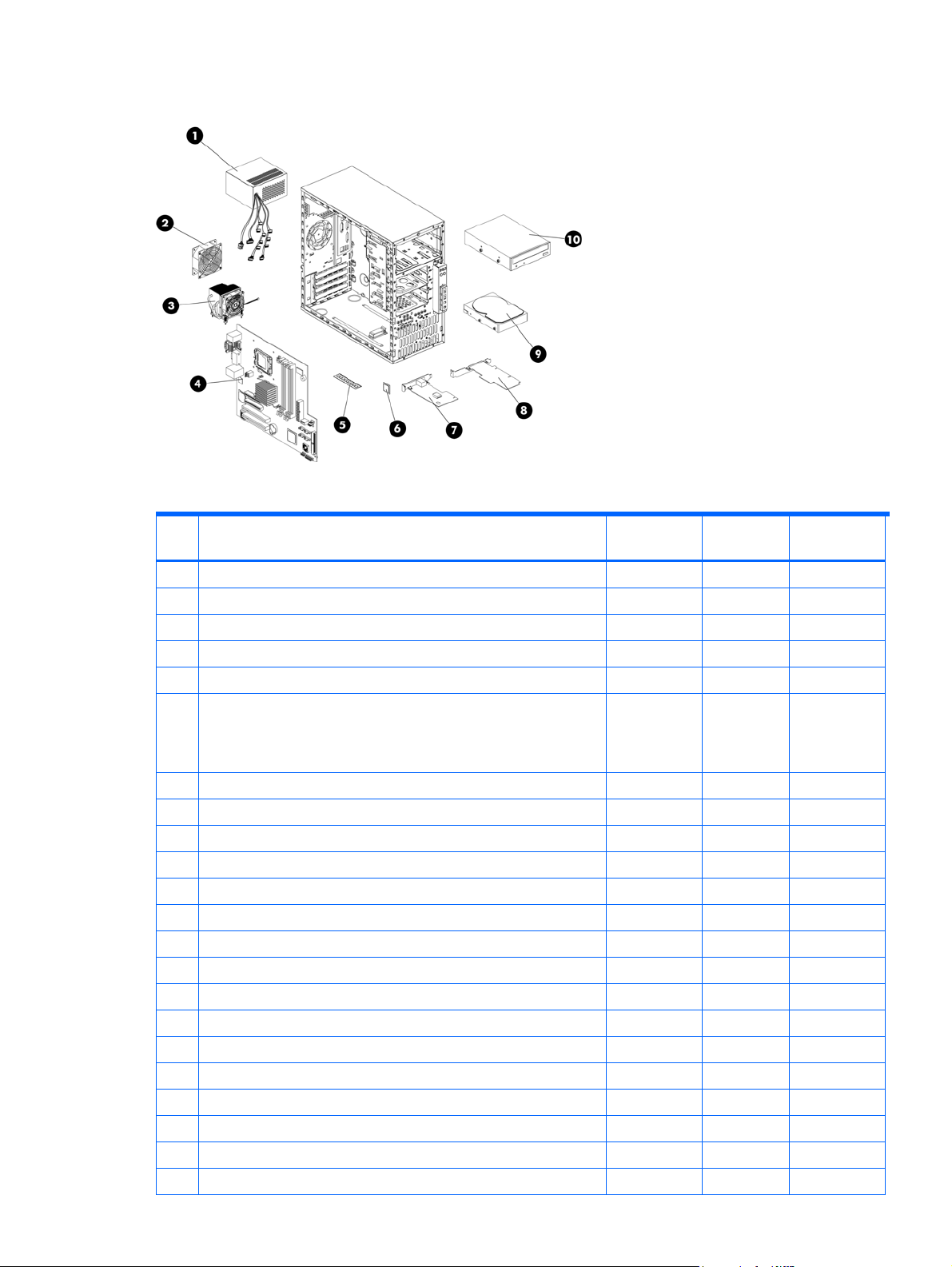
System components
Figure 2-2 System components
Table 2-2 System components spare parts list
Item Description
1 370-W power supply unit with cable assembly 416121-001 419029-001 Mandatory1
2 System fan 391976-001 392172-001 Mandatory1
3 Processor cooler assembly 418441-001 433549-001 Optional2
4 System board 416120-001 419028-001 Optional2
5 Memory module (PC2-5300 unbuffered ECC DDR II DIMM )
a) 512 MB 417440-051
b) 1 GB 417439-051 432930-001 Mandatory1
c) 2 GB 417438-061 433935-001 Mandatory1
6 Processors (include alcohol pad and thermal grease)
a) Intel® Xeon® 1.86GHZ/1066MHZ FSB with 2M L2 Cache 434381-001 436522-001 Optional2
b) Intel® Pentium® -D 915 2.8GHZ/800M FSB with 4M Cache 403277-101 436174-001 Optional2
c) Intel® Celeron® -D 3.2GHZ/533MHZ FSB with 512K Cache 408802-201 418779-001 Optional2
7 IPMI Card (HP Lights-Out 100c Remote Management Card) 418278-001 433556-001 Mandatory1
8 SAS card 435234-001 435709-001 Mandatory1
9 SAS/SATA hard drive
a) SATA hard drive 397377-002 399967-001 Mandatory1
b) SAS hard drive 375874-011 389343-001 Mandatory1
Mass storage devices
10 48X CD-ROM drive 266072-004 413383-001 Mandatory1
Misc parts
11 CD-ROM drive cable assembly, ATA100 * 430278-001 430413-001 Mandatory1
12 SAS hard drive cable * 430762-001 433550-001 Mandatory1
Assembly
number
(ALL)
417440-251
(BRZL)
Spare part
number
433555-001
Customer self
repair
Mandatory
1
Illustrated parts catalog 17
Page 18

Table 2-2 System components spare parts list
Item Description
Assembly
number
Spare part
number
Customer self
repair
13 SATA hard drive cable * 430274-001 430542-001 Mandatory1
14 USB/Power LED cable* 437907-001 440225-001 Mandatory1
*Not shown
1
Mandatory—Parts for which customer self repair is mandatory. If you request HP to replace these parts, you will be charged
for the travel and labor costs of this service.
2
Optional—Parts for which customer self repair is optional. These parts are also designed for customer self repair. If, however,
you require that HP replace them for you, there may or may not be additional charges, depending on the type of warranty
service designated for your product.
3
No—Some HP parts are not designed for customer self repair. In order to satisfy the customer warranty, HP requires that an
authorized service provider replace the part. These parts are identified as "No" in the Illustrated Parts Catalog.
1
Mandatory: Obligatoire—Pièces pour lesquelles la réparation par le client est obligatoire. Si vous demandez à HP de
remplacer ces pièces, les coûts de déplacement et main d'œuvre du service vous seront facturés.
2
Optional: Facultatif—Pièces pour lesquelles la réparation par le client est facultative. Ces pièces sont également conçues pour
permettre au client d'effectuer lui-même la réparation. Toutefois, si vous demandez à HP de remplacer ces pièces, l'intervention
peut ou non vous être facturée, selon le type de garantie applicable à votre produit.
3
No: Non—Certaines pièces HP ne sont pas conçues pour permettre au client d'effectuer lui-même la réparation. Pour que la
garantie puisse s'appliquer, HP exige que le remplacement de la pièce soit effectué par un Mainteneur Agréé. Ces pièces sont
identifiées par la mention “Non” dans le Catalogue illustré.
1
Mandatory: Obbligatorie—Parti che devono essere necessariamente riparate dal cliente. Se il cliente ne affida la riparazione
ad HP, deve sostenere le spese di spedizione e di manodopera per il servizio.
2
Optional: Opzionali—Parti la cui riparazione da parte del cliente è facoltativa. Si tratta comunque di componenti progettati
per questo scopo. Se tuttavia il cliente ne richiede la sostituzione ad HP, potrebbe dover sostenere spese addizionali a
seconda del tipo di garanzia previsto per il prodotto.
3
No: Non CSR—Alcuni componenti HP non sono progettati per la riparazione da parte del cliente. Per rispettare la garanzia,
HP richiede che queste parti siano sostituite da un centro di assistenza autorizzato. Tali parti sono identificate da un “No” nel
Catalogo illustrato dei componenti.
1
Mandatory: Zwingend—Teile, die im Rahmen des Customer Self Repair Programms ersetzt werden müssen. Wenn Sie diese
Teile von HP ersetzen lassen, werden Ihnen die Versand- und Arbeitskosten für diesen Service berechnet.
2
Optional: Optional—Teile, für die das Customer Self Repair-Verfahren optional ist. Diese Teile sind auch für Customer Self
Repair ausgelegt. Wenn Sie jedoch den Austausch dieser Teile von HP vornehmen lassen möchten, können bei diesem Service
je nach den für Ihr Produkt vorgesehenen Garantiebedingungen zusätzliche Kosten anfallen.
3
No: Kein—Einige Teile sind nicht für Customer Self Repair ausgelegt. Um den Garantieanspruch des Kunden zu erfüllen, muss
das Teil von einem HP Servicepartner ersetzt werden. Im illustrierten Teilekatalog sind diese Teile mit „No“ bzw. „Nein“
gekennzeichnet.
1
Mandatory: Obligatorio—componentes para los que la reparación por parte del usuario es obligatoria. Si solicita a HP que
realice la sustitución de estos componentes, tendrá que hacerse cargo de los gastos de desplazamiento y de mano de obra de
dicho servicio.
2
Optional: Opcional— componentes para los que la reparación por parte del usuario es opcional. Estos componentes
también están diseñados para que puedan ser reparados por el usuario. Sin embargo, si precisa que HP realice su
sustitución, puede o no conllevar costes adicionales, dependiendo del tipo de servicio de garantía correspondiente al
producto.
Illustrated parts catalog 18
Page 19
3
No: No—Algunos componentes no están diseñados para que puedan ser reparados por el usuario. Para que el usuario
haga valer su garantía, HP pone como condición que un proveedor de servicios autorizado realice la sustitución de estos
componentes. Dichos componentes se identifican con la palabra “No” en el catálogo ilustrado de componentes.
1
Mandatory: Verplicht—Onderdelen waarvoor Customer Self Repair verplicht is. Als u HP verzoekt deze onderdelen te
vervangen, komen de reiskosten en het arbeidsloon voor uw rekening.
2
Optional: Optioneel—Onderdelen waarvoor reparatie door de klant optioneel is. Ook deze onderdelen zijn ontworpen voor
reparatie door de klant. Als u echter HP verzoekt deze onderdelen voor u te vervangen, kunnen daarvoor extra kosten in
rekening worden gebracht, afhankelijk van het type garantieservice voor het product.
3
No: Nee—Sommige HP onderdelen zijn niet ontwikkeld voor reparatie door de klant. In verband met de
garantievoorwaarden moet het onderdeel door een geautoriseerde Service Partner worden vervangen. Deze onderdelen
worden in de geïllustreerde onderdelencatalogus aangemerkt met "Nee".
1
Mandatory: Obrigatória—Peças cujo reparo feito pelo cliente é obrigatório. Se desejar que a HP substitua essas peças,
serão cobradas as despesas de transporte e mão-de-obra do serviço.
2
Optional: Opcional—Peças cujo reparo feito pelo cliente é opcional. Essas peças também são projetadas para o reparo feito
pelo cliente. No entanto, se desejar que a HP as substitua, pode haver ou não a cobrança de taxa adicional, dependendo do
tipo de serviço de garantia destinado ao produto.
3
No: Nenhuma—Algumas peças da HP não são projetadas para o reparo feito pelo cliente. A fim de cumprir a garantia do
cliente, a HP exige que um técnico autorizado substitua a peça. Essas peças estão identificadas com a marca “No” (Não), no
catálogo de peças ilustrado.
HP contact information
For the name of the nearest HP authorized reseller:
Illustrated parts catalog 19
Page 20

• In the United States, call 1-800-345-1518.
• In Canada, call 1-800-263-5868.
• In other locations, refer to the HP website at http://www.hp.com/
For HP technical support:
• In North America:
• Call 1-800-HP-INVENT (1-800-474-6836). This service is available 24 hours a day, 7 days a week.
For continuous quality improvement, calls may be recorded or monitored.
• If you have purchased a Care Pack (service upgrade), call 1-800-633-3600. For more information
about Care Packs, refer to the HP website at http://www.hp.com/.
• Outside North America, call the nearest HP Technical Support Phone Center. For telephone numbers for
worldwide Technical Support Centers, refer to the HP website at http://www.hp.com/
Before you contact HP
Be sure to have the following information available before you call HP:
• Technical support registration number (if applicable)
• Product serial number
• Product model name and number
• Applicable error messages
• Add-on boards or hardware
• Third-party hardware or software
• Operating system type and revision level
.
.
Illustrated parts catalog 20
Page 21
3 Removal and replacement procedures
This chapter provides subassembly/module-level removal and replacement procedures for the HP ProLiant ML110
Generation 4 server.
Review the specifications of a new component before installing it to make sure it is compatible with the server.
When you integrate new components into the system, record its model and serial number, and any other
pertinent information for future reference. After completing any removal or replacement procedure, run the
diagnostics program to verify that all components operate properly.
Hardware configuration tools
In performing any hardware configuration procedure you may need the following tools:
• T-15 Torx screwdriver
• Flat-blade screwdriver
NOTE: The figures used in this chapter to illustrate procedural steps are labeled numerically (i.e., 1, 2…).
When these figures are used in substep items, the alphabetically labeled instructions correspond to the
numbered labels on the related figure (i.e., Label 1 corresponds to step a, label 2 corresponds to step b, etc.).
Hardware configuration information
WARNING! Only authorized technicians trained by HP should attempt to repair this equipment. Because of the
complexity of the individual boards and subassemblies, no one should attempt to make repairs at the
component level or to make modifications to any printed wiring board. Improper repairs can create a safety
hazard.
CAUTION: Electrostatic discharge (ESD) can damage electronic components. Be sure that you are properly
grounded (earthed) before beginning any installation procedure. Refer to the “Electrostatic Discharge
Information” section for more information.
Before removing any serviceable parts, determine whether the part is hot-plug or non-hot-plug.
Non-hot-plug device
If the device is non-hot-plug, you must power down the server. Non-hot-plug devices in the server include the
processor, all boards, memory modules, fans, PCI option cards, and all hard drives.
Electrostatic discharge information
ESD can damage static-sensitive devices or microcircuit. Proper packaging and grounding techniques are
necessary precautions to prevent damage. To prevent electrostatic damage, observe the following precautions:
• Transport products in static-safe containers such as conductive tubes, bags, or boxes.
• Keep electrostatic-sensitive parts in their containers until they arrive at static-free stations.
• Cover workstations with approved static-dissipating material. Use a wrist strap connected to the work
surface and properly grounded (earthed) tools and equipment.
• Keep work area free of nonconductive materials, such as ordinary plastic assembly aids and foam packing.
• Make sure that you are always properly grounded (earthed) when touching a static-sensitive component or
assembly.
• Avoid touching pins, leads, or circuitry.
• Always place drives with the Printed Circuit Board (PCB) assembly-side down.
• Use conductive field service tools.
Symbols on equipment
These symbols may be located on equipment in areas where hazardous conditions may exist.
Removal and replacement procedures 21
Page 22

Pre-installation instructions
Perform the steps below before you open the server or before you remove or replace any component:
WARNING! Failure to properly turn off the server before you open it or before you start
installing/removing components may cause serious damage as well as bodily harm.
1. Turn off the server and all the peripherals connected to it.
Refer to the Powering down the server section in this chapter for detailed instructions on how to completely
power down the server.
2. Unplug all cables from power outlets to avoid exposure to high energy levels that may cause burns if parts
are short-circuited by metal objects such as tools or jewelry. If necessary, label each cable for reassembly.
3. Disconnect telecommunication cables to avoid exposure to shock hazard from ringing voltages.
4. Open the server according to the instructions described in the System covers section in this chapter.
5. Follow the ESD precautions listed previously in this chapter when handling a server component.
Post-installation instructions
Observe the following items after installing or removing a server component:
1. Make sure that you install all components according to the described step-by-step instructions.
2. Make sure not to leave loose tools or parts inside the server.
3. Reinstall any expansion board(s), peripheral(s), and system cable(s) that have previously been removed.
4. Reinstall the system covers.
Removal and replacement procedures 22
Page 23

5. Connect all external cables and the AC power cord to the system.
6. Press the power button on the front panel to turn on the server.
CAUTION: Do not operate the server for more than 10 minutes with the access panel and drives removed.
Otherwise, improper cooling airflow may damage system components.
Powering down the server
To completely remove all power from the system, disconnect all power cords from the server.
WARNING! Hazardous voltages are present inside the server. Always disconnect AC power from the server
and other associated assemblies while working inside the unit. Serious injury may result if this warning is not
observed.
WARNING! To reduce the risk of injury from electric shock, disconnect all power cords to completely remove
power from the system.
WARNING! To reduce the risk of personal injury from hot surfaces, allow the internal system components to
cool before touching them.
CAUTION: Protect the server from power fluctuations and temporary interruptions with a regulating
uninterruptible power supply (UPS). This device protects the hardware from damage caused by power surges
and voltage spikes, and keeps the system in operation during a power failure.
CAUTION: The server must always be operated with the system covers on. Proper cooling is not achieved
when the system covers are removed.
To power down the server:
1. Shut down server as directed by the operating system documentation.
2. Disconnect the AC power cord from the AC outlet and then from the server.
3. Be sure that the power LED indicator is turned off and that the fan noise has stopped.
4. Disconnect all external peripheral devices from the server.
System covers
The access panel and the front bezel are both detachable. You must remove these system covers before you can
remove or replace a server component.
Access panel
CAUTION: You must remove the access panel to access internal components and mass storage devices.
To remove the access panel:
1. Loosen the captive thumbscrew located on the rear edge of the access panel.
2. Slide the panel back about 2.5 cm (1.0 in).
Figure 3-1 Removing the access panel
Removal and replacement procedures 23
Page 24

To reinstall the access panel:
1. Use two hands to place the access panel flat against the chassis, the back of the access panel extending
about 2.5 cm (1.0 in) behind the back of the server. Make sure the hooks on the access panel align with
the holes on the edges of the chassis.
2. Slide the access panel toward the front of the chassis to position it into place.
3. Tighten the captive thumbscrew to secure the access panel.
Figure 3-2 Reinstalling the access panel
Front bezel
CAUTION: You must remove the front bezel to access the hard drives and optical drives.
To remove the front bezel
1. Remove the access panel.
2. Remove the front bezel:
Figure 3-3 Removing the front bezel
a. Press in the three bottom tabs on the side of the bezel to release them from the chassis.
b. Rotate the bezel out slightly.
c. Pull the bezel away from the front panel.
To replace the front bezel:
1. Insert the two hooks on the right side of the bezel into the rectangular holes on the chassis.
2. Rotate the bezel into place so that the three tabs on the left side of the bezel snap into the slots on the
chassis.
Removal and replacement procedures 24
Page 25

Figure 3-4 Reinstalling the front bezel
Drives
You can install up to two optical drives and up to four hard drives in the server.
Cable management
Always follow good cable management practices when working inside the computer.
• Keep cables away from major heat sources like the cooler.
• Do not jam cables on top of expansion cards or memory modules. Printed circuit cards are not designed to
withstand excessive pressure.
• Keep cables clear of sliding or moveable parts to prevent cutting or crimping.
• When folding a flat ribbon cable, never fold to a sharp crease. Sharp creases may damage the wires.
• Some flat ribbon cables come refolded. Never change the folds on these cables.
• Do not sharply bend any cable. A sharp bend can break the internal wires.
• Never bend a SATA data cable tighter than a 30 mm (1.18 in) radius.
• Never crease a SATA data cable.
• Do not rely on components like the drive cage, power supply, or system cover to push cables down into the
chassis.
Removing power supply power cables from the system board connectors (P2, P3) follow below steps:
1. Squeeze on the top of the retaining latch attached to the cable end of the connector.
2. Grasp the cable end of the connector and pull it straight up.
CAUTION: Always pull the connector - NEVER pull on the cable. Pulling on the cable could damage the cable
and result in a failed power supply.
Figure 3-5 Unplugging power cables
Removal and replacement procedures 25
Page 26

Cable connections
The following table provides information about power supply cable connector labels, as well as system board
connector designators. The top half of the table indicates the label on the power supply cable. The bottom half of
the table provides the system board designators that various cables plug into. For more detailed information
about system board components, see System board components in Chapter 5.
Table 3-1 Cable connections
Cable To Cable Designator
Power supply System board P1
Power supply System board CPU power P2
Power supply 1st SATA hard drive P12
Power supply 2nd SATA hard drive P10
Power supply 3rd SATA hard drive P8
Power supply 4th SATA hard drive P6
Power supply 1st SAS hard drive P11
Power supply 2nd SAS hard drive P9
Power supply 3rd SAS hard drive P7
Power supply 4th SAS hard drive P5
Power supply 1st optical drive P3
Power supply 2nd optical drive P4
Cable To System board designator
CPU fan connector System board P70
Rear system fan System board P8
Front USB connector System board P24
Front panel connector System board P5
1st SATA connector System board P60
2nd SATA connector System board P61
3rd SATA connector System board P64
4th SATA connector System board P62
Internal USB tape drive System board J4
Internal USB port System board J3
Drive bay configuration
The server supports a maximum of six internal drives. The two upper drive bays are primarily for removable
media devices, while the four lower drive bays are only for hard drives. The two upper bays are half height IDE
optical bays. The four lower drive bays can accommodate non-hot-plug hard drives.
Removal and replacement procedures 26
Page 27

Figure 3-6 Drive bay configuration
st
1 1
Optical drive 4 3rd SAS/SATA hard drive
nd
2 2
Optical drive 5 2nd SAS/SATA hard drive
th
3 4
SAS/SATA hard drive 6 1
Releasing drives
1. A drive latch with release tabs secures the drives in the drive bay. Lift the release tab on the drive latch for
the drive you want to remove.
2. Slide the optical drive out from its bay.
Figure 3-7 Releasing drives
st
SAS/SATA hard drive
3. When replacing drives, remove the four guide screws (two on each side) from the old drive. You will need
these screws to install a new drive.
Optical drive
To replace an optical drive
1. Remove the optical drive from the server:
a. Disconnect the power and data cables from the rear of the optical drive.
b. A drive latch with release tabs secures the drives in the drive bay. Lift the release tab on the drive latch.
c. Slide the drive from the drive bay.
Removal and replacement procedures 27
Page 28

Figure 3-8 Removing an optical drive
2. Place the old optical drive on a static-dissipating work surface or inside of an anti-static bag.
3. Remove the new optical drive from its protective packaging.
4. Check that the IDE jumper on the rear section of the optical drive is set to Cable-Select mode.
5. Install the new optical drive:
a. Insert four screws (two on each side) into the new optical drive.
b. Guide the new optical drive into the optical bay, with the cable connectors facing the rear of the
chassis, and then push the drive all the way into the drive bay until the drive clicks into place.
c. Connect the IDE power and data cables to their connectors on the rear of the drive.
Figure 3-9 Installing an optical drive
Optional media device
The lower half-height drive bay can be used for an optional optical drive.
To install an optional optical drive
1. Remove the drive shield to prepare the bay for drive installation:
a. Remove the screw that secures the drive shield.
b. Pull the shield out of the chassis. Store it for later use.
CAUTION: Do not discard the shield. If the drive is removed in the future, you must reinstall the shield to
maintain proper system function.
Removal and replacement procedures 28
Page 29

Figure 3-10 Removing the drive shield
2. Install the new drive:
a. Insert four screws (two on each side) into the new optical drive.
b. Guide the new drive into the bay, with the cable connectors of the drive facing the rear of the chassis,
and then push the drive all the way into the chassis until the drive clicks into place.
c. Connect the power and data cables to the connectors on the rear of the drive.
Figure 3-11 Installing an optional media drive
Hard drives
You can install either SAS hard drives or SATA hard drives in the server. The bottom four bays are the hard drive
bays.
CAUTION: SAS hard drives require that you also install a SAS expansion card. Connect the hard drive data
cable from the hard drive to the SAS expansion card. Then connect power cable from the power supply to the
back of hard drive. For more information about installing expansion cards, see Expansion cards.
To remove hard drive:
1. Disconnect the power and data cables from the back of the installed drive.
2. A drive latch with release tabs secures the hard drives in the drive bay. Lift the release tab on the drive
latch.
3. Slide the hard drive from the drive bay.
NOTE: Remove the four screws from the sides of the drive. You will reuse these screws when you install the
new hard drive.
Removal and replacement procedures 29
Page 30

Figure 3-12 Removing a hard drive
To install the new hard drive:
1. Insert the four drive screws (two on each side) into the hard drive.
2. Slide the new hard drive into the selected bay until it clicks into place.
3. Connect the power cable from the power supply to the back of the hard drive.
Figure 3-13 Installing a hard drive
CAUTION: If you are installing a SATA hard drive, connect the data cables from the system board to the back
of the hard drive and connect the power cable from the power supply to the back of the hard drive.
CAUTION: If you are installing a SAS hard drive, connect the data cable from the SAS expansion card to the
back of the hard drive.
NOTE: If you want to install a new hard drive in an empty drive bay, remove four screws from the front of the
chassis labeled ‘HDD SCREWS’ in the below figure for the location of these spare screws.
Removal and replacement procedures 30
Page 31

Figure 3-14 Drive screw location
Drive latch
You can remove the latch that secures and allows removal of the drives.
To remove the drive latch:
1. Pull the latch to loosen the two tabs that secure the latch to the chassis.
2. Slide the latch straight down and remove it from the chassis.
NOTE: To loosen the latch, you may also have to pull the tabs that secure inserted drives. Drive latch tabs may
break during removal.
Figure 3-15 Removing the drive latch
To install new drive latch:
1. Insert the two tabs on the top of the latch into their holders near the top of the chassis.
2. Slide the latch upward until the two tabs in the middle of the latch click into place.
Removal and replacement procedures 31
Page 32

Figure 3-16 Installing the drive latch
System board components
Refer to the following sections for instructions about how to remove or replace the processor, the memory
modules, the expansion cards, and the system battery.
Processor
The LGA775 processor socket supports Intel® Pentium®4, Intel® Pentium® -D, Celeron® -D processors, and Xeon®
3000 series processors.
Figure 3-17 LGA775 processor socket location
WARNING! To reduce the risk of injury from a hot component, allow the surface to cool before touching.
To remove cooler assembly:
NOTE: Lay the server on its side with the open side facing up.
NOTE: If necessary, remove any accessory boards or cables that prevent access to the processor socket.
1. Disconnect the processor fan cable from the connector on the system board (P70).
2. Twist the mounting pins counterclockwise to loosen them.
3. After you loosen all four mounting pins, lift cooler away from the system board.
Removal and replacement procedures 32
Page 33

Figure 3-18 Removing cooler assembly
CAUTION: Place cooler down in an upright position with the thermal patch facing upward. Do not let the
thermal patch touch the work surface.
To remove the processor:
1. Disengage the load lever.
2. Lift the retention plate to expose the socket body.
3. Grasp the processor by its edges and lift it out of the socket.
Figure 3-19 Removing the processor
CAUTION: Place the processor on a static-dissipating work surface or in an anti-static bag.
CAUTION: To allow cooler to draw as much heat as possible from the processor base, there must be good
contact between the cooler base and the top of the processor. To ensure good contact, you must apply thermal
grease compound.
Apply the thermal grease compound:
1. Use a clean cloth dipped in rubbing alcohol to clean the contact surface on the cooler and on the new
processor. Wipe the contact surfaces several times to make sure they are free of particles or dust
contaminants.
2. Apply the thermal grease compound to the CPU contact surface.
3. Use a proper tool to spread the grease throughout the entire contact surface and lightly scrape off any
excess grease.
CAUTION: Never touch the bottom size of the processor; any contaminant could prevent the processor contact
pads from making contact with the socket.
CAUTION: It is recommended to use the thermal grease of X-23-7783D made by Shin-Etsu.
Removal and replacement procedures 33
Page 34

CAUTION: Applying too much grease creates a gap between the contact surfaces, significantly reducing the
ability of the cooler to draw out heat. Installing the cooler with excessive grease can also cause the grease to
spread over the processor pins or the system board base, which can cause electrical shorts that damage the
system.
To install the new processor:
1. With the load lever and the retention plate disengaged, hold the processor by its edges and align it over
the empty processor socket. Make sure that you properly align the processor with the orientation notch on
the socket.
2. Insert the processor into the socket.
3. Engage the retention plate.
4. Engage the load lever.
Figure 3-20 Installing a processor
CAUTION: After you install the processor, you must reinstall the cooler on top of the processor socket. The
thermal grease you applied on the contact surfaces of the cooler and the processor provides the necessary
thermal bonding to allow the cooler to draw heat from the processor.
CAUTION: To prevent processor overheating or system instability, use only a cooler assembly specified for the
HP ProLiant ML110 Generation 4 server.
To replace cooler assembly:
1. Properly align the cooler mounting pins to the system board mounting holes and press down until you hear
a click.
2. Twist the mounting pins clockwise to secure the cooler connection to the system board.
3. Connect the processor fan cable to the connector on the system board (P70).
CAUTION: Failure to connect the processor fan cable to the system board may result in damage to the
processor and could cause the server to shut down without displaying messages.
Removal and replacement procedures 34
Page 35

Figure 3-21 Installing the cooler assembly
Memory
The HP ProLiant ML110 Generation 4 server has four DIMM slots that support up to 8 GB maximum system
memory (2 GB in each of the four DIMM slots).
Figure 3-22 DIMM slots location
Guidelines for installing memory modules
You must adhere to the following guidelines when adding or replacing memory modules:
• Use only DDR II 533/667 unbuffered ECC DIMMs in 512 MB, 1 GB or 2 GB module.
• Up to two DIMMs per channel, single-sided and/or double-sided. Channel A corresponds to the DIMM1
and DIMM2 slots, while channel B corresponds to the DIMM3 and DIMM4 slots.
• For optimal 2 DIMMs configuration, populate slot 1 and slot 3. Identical DIMMs are recommended.
To remove memory module:
NOTE: Lay the server on its side with the open side facing up.
NOTE: If necessary, remove any accessory boards or cables that prevent access to the processor socket.
1. Completely open the holding clips securing the module.
2. Gently pull the memory module upward to remove it from the socket.
Removal and replacement procedures 35
Page 36

Figure 3-23 Removing a memory module
CAUTION: Place the memory module on a static-dissipating work surface or inside of an anti-static bag.
To Install a memory module:
1. Orient the module so that the notch on the bottom edge of the module aligns with the keyed surface of the
DIMM socket, and then press it fully into the socket.
2. Firmly press the latches inward to secure the memory module in place.
Figure 3-24 Installing a memory module
CAUTION: The memory sockets are structured to ensure proper installation. If you insert a memory module but
it does not fit easily into the socket, you may have inserted it incorrectly. Double-check the orientation of the
module and reinsert. If the latches do not close, the module is not inserted correctly.
Expansion cards
PCI card
You must remove the PCI expansion slot cover lock before installing or removing expansion cards.
The server supports the following:
• Two 32-bit/33-MHz 3.3V PCI slots (J20 to J21)
• One PCI-Express x4 link with x8 slot (J33)
• One PCI Express x8 link with x8 slot (J32)
Removal and replacement procedures 36
Page 37

Figure 3-25 PCI slot location
To remove the PCI slot cover lock:
1. Remove the retaining screw that secures the lock to the chassis.
2. Remove the slot cover lock from the chassis.
Figure 3-26 Removing the PCI slot cover lock
3. Remove the PCI bracket from the chassis.
NOTE: If necessary, remove any accessory boards or cables that prevent access to the PCI slots.
CAUTION: Do not discard the PCI bracket. If the PCI expansion card is removed in the future, the PCI bracket
must be reinstalled.
To remove the PCI card:
1. Hold the card at both ends, and then carefully rock the card back and forth until the expansion cards pull
free from the slot.
2. Store the old card in the anti-static packaging.
Removal and replacement procedures 37
Page 38

Figure 3-27 Removing the PCI card
To install the PCI card:
1. Hold the card above the expansion slot on the system board, and then move the card toward the rear of
the chassis so that the bracket on the card is aligned with the open slot on the rear of the chassis.
2. Press the card straight down into the expansion slot on the system board.
Figure 3-28 Installing a PCI card
3. Replace the PCI slot cover lock:
a. Slide the PCI slot cover lock onto the rails toward the server.
b. Replace the slot cover lock retaining screw.
Figure 3-29 Replacing the PCI slot cover
4. Connect required cables to the card.
Removal and replacement procedures 38
Page 39

HP Smart Array E200 controller card
You must remove the PCI expansion slot cover lock and the PCI guide before installing HP Smart Array E200
controller card.
Figure 3-30 HP Smart Array E200 controller card slot location
To remove the PCI slot cover lock:
1. Remove the retaining screw that secures the lock to the chassis.
2. Remove the slot cover lock from the chassis.
Figure 3-31 Removing the PCI slot cover lock
3. Remove the PCI bracket from the chassis.
NOTE: If necessary, remove any accessory boards or cables that prevent access to the PCI slots.
CAUTION: Do not discard the PCI bracket. If the PCI expansion card is removed in the future, the PCI bracket
must be reinstalled.
To remove the PCI guide:
1. Remove the PCI guide from the hard drive support to prepare for the HP Smart Array E200 controller card
installation.
2. Pull the PCI guide from the hard drive cage support as shown in the below figure.
Removal and replacement procedures 39
Page 40

Figure 3-32 Removing the PCI guide
To install a HP Smart Array E200 controller card:
1. Hold the card above the expansion slot on the system board, and then move the card toward the rear of
the chassis so that the bracket on the card is aligned with the open slot on the rear of the chassis.
2. Press the card straight down into the expansion slot on the system board.
Figure 3-33 Installing a HP Smart Array E200 controller card
3. Reinstall the PCI guide to secure the HP Smart Array E200 controller card:
a. Properly align the PCI guide to the edge of HP Smart Array E200 controller card and hard drive
support.
b. Slide the PCI guide around the edge of HP Smart Array E200 controller card, and slide the other side
of PCI guide inside the hard drive support until the PCI guide click into place.
Figure 3-34 Reinstalling the PCI guide
4. Replace the PCI slot cover lock:
Removal and replacement procedures 40
Page 41

a. Slide the PCI slot cover lock onto the rails toward the server.
b. Replace the slot cover lock retaining screw.
Figure 3-35 Replacing the PCI slot cover
5. Connect required cables to the card.
System battery
The server uses volatile memory that requires a battery to retain system information when power is removed. This
3-volt lithium coin cell battery is located on the system board.
Figure 3-36 System battery location
If the server no longer automatically displays the correct date and time, you may need to replace the system
battery. Under normal use, battery life is five to ten years.
WARNING! Note the following reminders when replacing the system battery:
•
Replace the battery with the same type as the battery recommended by HP. Use of another battery may present a risk of
fire or explosion.
• A risk of fire and chemical burn exists if the battery is not handled properly. Do not disassemble, crush, puncture, or
short external contacts, or expose the battery to temperatures higher than 60°C (140°F).
• Do not dispose of used battery in water or fire. Dispose of used batteries according to the manufacturer's instructions.
CAUTION: Loss of BIOS settings occurs when the battery is removed. You must reconfigure BIOS settings
whenever you replace the battery.
To replace the system battery:
NOTE: Lay the server on its side for better access to the battery holder (XBT2).
NOTE: If necessary, remove any accessory boards or cables that prevent access to the battery holder.
1. To release the battery from its holder, squeeze the metal clamp that extends above one edge of the battery.
When the battery pops up, lift it out.
Removal and replacement procedures 41
Page 42

2. To insert the new battery, slide one edge of the replacement battery under the holder’s lip with the positive
side up. Push the other edge down until the clamp snaps over the other edge of the battery.
Figure 3-37 Replacing the battery
Power supply unit (PSU)
Located on the rear panel of the server power supply is a single standard auto-range 370-watt PSU with PFC
(power factor correction) function.
WARNING! Note the following reminders are to reduce the risk of personal injury from electric shock hazards
and/or damage to the equipment.
•
Installation of power supply units should be referred to individuals who are qualified to service server systems and are
trained to deal with equipment capable of generating hazardous energy levels.
• DO NOT open the power supply unit. There are no serviceable parts inside it.
To remove the power supply:
NOTE: Lay the server on its side with the open side facing up.
1. Disconnect the power cables of all installed drives from the PSU.
2. Remove the four screws that secure the PSU to the chassis.
3. Lift the PSU out of the chassis.
Figure 3-38 Removing the PSU
To install new PSU:
1. Align the new PSU to the support edges inside of the chassis.
2. Secure the PSU to the chassis using four screws.
3. Reconnect the processor and system board power cables to the system board connectors (P2, P3), and then
connect the power cables to all installed drives.
Removal and replacement procedures 42
Page 43

Figure 3-39 Installing the PSU
System fan
A new system fan can be installed to allow the server to operate properly in case the default system fan becomes
defective.
To remove the system fan:
WARNING! Be sure to support the system fan with your hand when removing screws from the chassis. The fan
could fall onto the system board or an accessory board causing damage if not supported.
1. Disconnect the system fan cable from its connector (P8) on the system board.
2. Remove the four screws from the rear of the chassis that secure the fan.
3. Remove the fan from the chassis.
Figure 3-40 Removing the system fan
To install new system fan:
1. Align the new fan to the screw holes inside of the chassis.
2. While holding the new fan against the chassis, replace the four screws that secure the fan to the chassis.
3. Connect the system fan cable to its connector (P8) on the system board.
Removal and replacement procedures 43
Page 44

Figure 3-41 Installing the system fan
Removal and replacement procedures 44
Page 45

Install IPMI Card
IPMI card (HP Lights-Out 100c remote management card) is a suite of products that enable remote management
of ProLiant 100c Series servers. IPMI card allows customers or their service providers to remotely manage
ProLiant ML110 G4 servers over a LAN or the Internet. With IPMI card, users can access a system's text console,
control system power, and monitor system environmental conditions from a browser or command line.
Figure 3-42 IPMI card connector location
CAUTION: PCI-E x8 Connector is only for HP ProLiant ML110 Generation 4 IPMI card.
To install the IPMI card:
1. Back up the server data.
2. Shut down the operating system in an orderly manner, as directed in the operating system instruction.
3. If the server is on, press the power button to power down the server.
4. All power cords must be disconnected.
5. Remove the access panel.
6. Loosen the screw to remove the IPMI card bracket dummy from the chassis.
7. Press the card straight down into the expansion slot on the system board.
8. Be sure the card is at the correct position and the bracket on the card is aligned with the open slot on the
rear of the chassis.
9. Fasten the expansion card bracket on the rear panel with screw.
Figure 3-43 Installing the IPMI card
10. Replace the access panel.
11. Reconnect all power cords.
CAUTION: The LAN port on the IPMI card is dedicated to LO100c 10/100 LAN Management Port.
Removal and replacement procedures 45
Page 46

4 Diagnostic tools and Setup Utilities
This chapter provides an overview of the Power-On Self-Test (POST), the POST error messages, and BIOS, SAS
and SATA setup utilities.
BIOS Software
The Generation 4 server uses BIOS to boot up the system. BIOS software is a ROM BIOS-based firmware that
allows reliability, manageability, and connectivity for server platforms. This software contains a set of programs
permanently stored in an EEPROM chipset located on the system board. These programs assist in managing,
initializing, and testing the hardware devices installed on the computer.
BIOS software allows you to:
• Perform configuration from the BIOS Setup Utility
Using the Setup Utility, you can install, configure, and optimize the hardware devices on the system board.
In addition, you can enable various features such as serial console redirection, PXE boot, and much more.
• Initialize hardware at boot up using POST routines
During power-on or warm reset, the BIOS perform Power-On Self-Test (POST) routines to test system
components, to allocate resource for various hardware devices, and to prepare the system to boot to
various operating systems.
BIOS Setup Utility
The HP server BIOS Setup Utility is used to configure five primary menu selections :
• Main
• Advanced
• Security
• Boot
• Exit
Accessing the BIOS Setup Utility
1. Turn on the monitor and server. If the server is already turned on, save your data and exit all open
applications, then restart the server.
2. When the HP logo is displayed during POST, press F10. If you fail to press F10 before POST is completed,
you will need to restart the server.
3. The first page displayed is the Main menu showing the Setup Utility menu bar. Use the left (←) and right
(→) arrow keys to move between selections on the menu bar. Use the up (↑) and down (↓) arrow keys to
select items within a menu.
Navigating through the Setup Utility
Use the keys listed in the legend bar on the right of the Setup screen to navigate through the various menu and
submenu screens of the Setup Utility. Table 4-1 lists these legend keys and their respective functions.
Table 4-1 Setup Utility Navigation Keys
Key Function
← and → To move between selections on the menu bar.
↑ and ↓ To move the cursor to the field you want.
The currently selected field is highlighted. The right side of each menu screen displays a field help
panel—Item Specific Help panel. This panel displays the help text for the currently selected field. It
updates as you move the cursor to each field
Diagnostic tools and Setup Utilities 46
Page 47

Table 4-1 Setup Utility Navigation Keys
Key Function
+ (or F6), – (or F5)
and <Space>
To select a value for the currently selected field (only if it is user-configurable).
Press the (+), (–) or <Space> keys repeatedly to display each possible entry, or the Enter key to choose
from a pop-up menu.
A parameter that is enclosed in square brackets is user-configurable.
Grayed-out parameters are not user-configurable for one of the following reasons:
• The field value is auto-configured or auto-detected.
• The field value is informational only.
• The field is password-protected.
Enter To select a field value or display a submenu screen.
Displays more option for items marked with
Ctrl+Enter To expands all device list
Esc or <Alt+X> If you press this key:
• On one of the primary menu screens, the Exit menu displays.
• On a submenu screen, the previous screen displays.
• When you are making selections from a pop-up menu, the pop-up closes without making a selection.
F1 or <Alt+H> To bring up the General Help window.
The General Help window describes other Setup navigation keys that are not displayed on the legend
bar.
<Page Up> and
<Page Down>
<Home> and
<End>
F9 To load default system values.
F10 To save changes and close the Setup Utility.
Moves to previous/next page on scrollable menus.
Moves to top/bottom item of current menu.
Figure 4-1 Setup Utility General Help screen
Press F1 to get the general help massage box.
Diagnostic tools and Setup Utilities 47
Page 48

Setup Utility Menu Bar
The BIOS Setup Utility provides a menu bar with the menu selections. The menu bar choices are described in the
topics below.
Main Menu
Figure 4-2 Main menu of the BIOS Setup Utility
Use this menu to set the system time and date, and configure the following items:
• Set system time and date.
• Set boot features:
a. Enable or disable the BIOS summary display.
b. Turn on or off boot up Num Lock.
c. Set restore on AC power loss options, such as last state, power off, and power on.
d. If BIOS displays an error message, set POST F1 Prompt for selections, such as delayed, enabled, or
disabled.
• View CPU type / CPU speed information.
• View Installed memory size.
• View MAC address for the embedded NIC.
• View System serial ID.
• Set Server Asset Text.
Diagnostic tools and Setup Utilities 48
Page 49

Advanced Menu
Figure 4-3 Advanced menu of the BIOS Setup Utility
WARNING! Incorrect settings may cause the server to malfunction. To correct the settings, press F9 key to
restore the default settings.
• Advanced Chipset Control ---- Configure the advanced chipset control settings such as the SATA controller
mode.
• Advanced Processor Options --- Enable or disable single logical processor and Intel Virtualization
technology for the processor supported.
• Harddisk Configuration --- Configure the hard disk settings of the server.
View CD-ROM status and SATA hard drive status.
• USB Configuration --- Configure the USB settings of the server.
• 8042 Emulation Support --- Normally enabled. Disable for Red Hat Linux 64bit installation.
• I/O Device Configuration --- Configure the serial port settings of the server.
• DMI Event Logging --- Allow you to view the DMI event log, clear the log, enable or disable this feature, and
mark the event as read.
• Embedded NIC PXE --- Enable or disable PXE boot support.
• IPMI --- Configure the Intelligent Platform Management Interface (IPMI) settings.
• Console Redirection --- Configure the settings when redirect the console to a serial port.
Diagnostic tools and Setup Utilities 49
Page 50

IPMI Submenu
Figure 4-4 IPMI submenu of the BIOS Setup Utility 1
Figure 4-5 IPMI submenu of the BIOS Setup Utility 2
Security Menu
Figure 4-6 Security menu of the BIOS Setup Utility 1
Diagnostic tools and Setup Utilities 50
Page 51

Figure 4-7 Security menu of the BIOS Setup Utility 2
Use this menu to configure the following items:
• Administrator Password Is --- Display if an administrator password is set.
• Set Administrator Password --- Allows you to access and change all settings in the Setup Utility. The
administrator password allows you to configure access for system users.
• Password on boot --- If an administrator password has been set, use this item to enable or disable the
requirement of the administrator password when booting the server.
To set a new administrator password:
1. In the Security screen, select a set password field - Set Administrator Password, and then press Enter.
2. Type a new password in the Enter New Password box.
Diagnostic tools and Setup Utilities 51
Page 52

3. The password may consist of up to eight alphanumeric characters (A-Z, a-z, 0-9).
4. Retype the password to verify the first entry, and then press Enter.
5. Press F10 to close the Setup Utility.
6. After setting the password, Setup automatically sets the selected password field to Enabled.
Boot Menu
Figure 4-8 Boot menu of the BIOS Setup Utility
Use this menu to configure the boot priority.
Set boot device priority. By default, the server searches for boot devices in the following order:
1. CD-ROM/DVD-ROM drives
2. Removable devices
3. Hard drive
4. Embedded NIC
Diagnostic tools and Setup Utilities 52
Page 53

Exit Menu
Figure 4-9 Exit menu of the BIOS Setup Utility
Use this menu to save changes or discard changes. When you exit, the server reboots.
• Exit Saving Changes --- Save the changes you have made and exit the BIOS Setup Utility. (You can also
press F10 key.)
• Exit Discarding Changes --- Exit the BIOS Setup Utility without saving the changes you have made. (You can
also press Esc key.)
• Load Setup Defaults --- Load the factory default values for all items. (You can also press the F9 key.)
• Discard Changes --- Discard any changes you have made.
• Save Changes --- Save the changes you have made.
BIOS Update
Perform the steps below to update BIOS:
1. Download the Smart Component (SPxxxxx.exe) to a directory on your hard drive.
2. Execute (SPxxxxx.exe) and followed with direction to complete the steps. “ProLiant Flash Update” interface
will appear.
3. Select items which need to update:
• Create a bootable ROMPAQ diskette
• Create a bootable ROMPAQ USB Key
• Create a bootable ROMPAQ CD
• ROMPAQ Diskette Flat Files
• Create a label for the ROMPAQ diskette
• Network ROM Flashing Capabilities
4. Reboot ML110 Generation 4 Server with one of the above bootable devices and make sure the BIOS
setting allows booting from the USB disk.
5. Follow the on-screen instructions to finish the flashing of the BIOS.
Clear CMOS
You may need to clear the Setup configuration values (CMOS) if the configuration has been corrupted, or if
incorrect settings made in the Setup Utility have caused error messages to be unreadable.
Diagnostic tools and Setup Utilities 53
Page 54

To clear CMOS:
1. Perform the pre-installation instructions listed in Chapter 3.
2. If necessary, remove any accessory boards or cables that prevent access to the system configuration switch.
3. Locate the system configuration button (SW2) on the system board.
4. Press the button. AC power must not be connected.
5. Perform the post-installation instructions listed in Chapter 3.
6. During POST, press F10 to access the Setup Utility.
7. Load setup defaults by pressing F9.
8. Set time, date, and other system values.
9. Press F10 to close the Setup Utility.
NOTE: Clearing CMOS deletes all system configurations and password settings.
Power-On Self-Test (POST)
Before you can use a server, all devices must be tested and initialized, and the operating system must be
bootstrapped to the memory. This is referred to as Power–On Self-Test or POST. POST is a series of diagnostic
tests that checks firmware and hardware components on the system to ensure that the server is properly
functioning. This diagnostic function automatically runs each time the server is powered on.
These diagnostics, which reside in the BIOS ROM, isolate server-related logic failures and indicate the board or
component that you need to replace, as indicated by the error messages. Most server hardware failures will be
accurately isolated during POST. The number of tests displayed depends on the configuration of the server.
During POST you can:
• Press ESC to skip the HP logo and go to POST boot progress display system summary screen.
• Press F7 to display the Boot menu.
• Press F10 to access the Setup Utility.
• Press F12 to request a network boot (PXE).
POST Error Indicators
When POST detects a system failure, it displays a POST error message.
Recoverable POST Errors
Whenever a non-fatal error occurs during POST, an error message describing the problem appears onscreen.
These error messages are displayed in normal video (white text on black background), and show the details of
the error. The following is an example of a POST error message:
0271 – Check date and time settings
Table 4-2 lists the most common POST error messages with corresponding troubleshooting recommendation. HP
recommends that you correct the error, even if the server appears to boot successfully.
Table 4-2 POST Error Messages
Error Code Error Message Description / Corrective Action
0200 Failure fixed disk A fixed disk did not respond. Remove A/C power momentarily then try again.
0210 Stuck key A key on the keyboard is stuck down. Release the key or replace the keyboard.
0211 Keyboard error The keyboard did not respond. If the error continues, replace the keyboard.
0212 Keyboard controller
failed
0213 Keyboard locked - Unlock
key switch
0250 System battery is dead –
Replace and run SETUP
If this does not resolve the error, an unrecoverable hardware error has
occurred.
Try a different keyboard. If the error persists, main board replacement may be
required.
A keyboard with a lock option is reporting that the lock is active.
The CMOS battery is discharged. It must be replaced.
Diagnostic tools and Setup Utilities 54
Page 55

Table 4-2 POST Error Messages
Error Code Error Message Description / Corrective Action
0260 System timer error The 8254 timer did not respond as expected. Main board replacement may be
required.
0270 Real time clock error The real time clock did not respond. Main board replacement may be required.
0271 Check date and time
settings
0280 Previous boot incomplete
- Default configuration
used
02D0 System cache error -
Cache disabled
0230 System RAM Failed at
offset:
0231 Shadow Ram Failed at
offset:
0232 Extended RAM Failed at
address line:
0251 System CMOS checksum
bad - Default
configuration used
02F5 DMA test failed The DMA controller did not respond. Main board replacement may be
02F9 CPU Fan error The CPU Fan did not respond. Replace the CPU Fan.
02FA Rear Fan error The Rear Fan did not respond. Replace the Rear Fan.
The system date or time is invalid. If the error returns after resetting date and
time, CMOS battery replacement may be required.
Setup changes were not saved because of a boot failure. Reapply setup
changes and boot again.
A processor reported an uncorrectable cache error. Replacement is required.
An uncorrectable memory error has occurred. Replace memory modules.
An uncorrectable memory error has occurred. Replace memory modules.
An uncorrectable memory error has occurred. Replace memory modules.
CMOS memory has been corrupted. This message is normal after the CMOS
battery is replaced.
required.
POST Related Troubleshooting
Perform the following procedures when POST fails to run, displays error messages, or emits beep codes.
If the POST failure is during a routine boot up, check the following:
• All external cables and power cables should be firmly plugged in.
• The power outlet to which the server is connected and is working.
• The server and monitor are both turned on. The bicolour status LED indicator on the front panel must be lit
up green.
• The monitor's contrast and brightness settings are correct.
• All internal cables are properly connected and all boards firmly seated.
• The processor is fully seated in its socket on the system board.
• The cooler assembly is properly installed on top of the processor.
• All memory modules are properly installed.
• If you have installed a PCI accessory board, verify that the board is firmly seated and any switches or
jumpers on the board are properly set. Refer to the documentation provided with the accessory board.
• All internal cabling and connections are in their proper order.
• If you have changed any switches on the system board, verify that each is properly set.
Diagnostic tools and Setup Utilities 55
Page 56

5 Connectors, switches and LEDs
This chapter contains illustrations and tables identifying and describing the connectors, switches, buttons, and
LED indicators located on the front panel, rear panel, system board and hard drives of the HP ProLiant ML110
Generation 4 server.
Connectors and components
This section contains illustrations and tables identifying connectors and components on the front and rear panels
of the server, as well as those located on the system board.
Front panel components
Figure 5-1 Front panel components
1 Optical drive 8 Drive activity indicator
2 Optical drive manual eject hole 9 Front USB 2.0 ports
3 Optical drive eject button 10 Hard drive EMI shield
4 Optical drive activity indicator 11 Hard drive EMI shield screw
5 Half-height common bay 12 Optical drive spare screws
6 Power button 13 Hard drive spare screws
7 Power LED indicator
Rear panel components
Figure 5-2 Rear panel components
1 PSU fan 9 IPMI card (HP LO 100c Remote Management Card) port
2 PS/2 mouse port 10 PCI slot covers
Connectors, switches and LEDs 56
Page 57

3 PS/2 keyboard port 11 Kensington lock notch
4 Serial port B 12 Power supply outlet
5 Serial port A 13 Rear system fan
6 VGA port 14 Thumbscrew for access panel
Rear USB 2.0 ports
7
8 LAN port (RJ-45) 16 PCI expansion slot cover lock
System board components
Figure 5-3 System board components
15 Cable lock provision tab
Table 5-1 System board components
Item Component Code Description
1 DIMM1 - 4 DDRII slots
2 P70 4-pin CPU fan connector
3 U3 Intel® Mukilteo 2 (MCH)
4 XU1 Intel® LGA775 CPU socket
5 P3 4-pin ATX CPU power connection
6 P8 4-pin system fan connection (rear)
7 J68 Top: PS/2 mouse port
Bottom: PS/2 keyboard port
8 P53 Serial port A
Serial port B
9 J69 VGA port
10 J9 Top: LAN port
Bottom: USB 2.0 ports
11 U1033 Broadcom 5721 GbE chip
12 J32 PCI-Express x 8 line with x 8 slot
13 U11 Server Engines Chip
14 J5 SMC FW
15 J20, J21 32-bit/33-MHz 3.3V PCI bus slot
16 J33 PCI-Express x 4 line with x 8 slot
17 XBT2 Battery
18 J10 IPMI card (HP LO 100c Remote Management Card) slot
19 U38 Intel® ICH7R
Connectors, switches and LEDs 57
Page 58

Table 5-1 System board components
Item Component Code Description
20 J2 System BIOS
21 P24 Front USB connector
22 P5 Front panel connector
23 P23 IDE channel UDMA-100
24 P60, P61,P62,P64 SATA 1-4 connector
25 J4 Internal USB connector for Tape
26 J3 Internal USB connector
27 P2 24-pin ATX system board power connector
28 SP1 Internal buzzer
Jumpers – Password and Boot Block
The system board password (P137) and boot block (P136) jumpers. Table 5-2 describes the jumper settings.
Table 5-2 System configuration switch settings
Jumper Status Function
Clear CMOS button
The system board has a system configuration (CMOS) button (SW50). To clear system configuration, disconnect
AC power and press the CMOS button.
Status LED indicators
This section contains illustrations and descriptions of internal and external status LED indicators located on the:
• Front panel
• Rear panel
• System board
These LED indicators aid in problem diagnosis by indicating the status of system components and operations of
the server.
Front panel LED indicators
The front panel LED indicators allow constant monitoring of basic system functions while the server is operating.
On (default) Password enabled. P137
Off Password reset/disabled.
On Boot block unprotected. P136
Off (default) Boot block protected.
Optical drive activity LED indicator
The optical drive has an activity indicator that indicates when the drive is reading media.
Connectors, switches and LEDs 58
Page 59

Figure 5-4 Optical drive activity LED indicator location
Activity states for the optical drive are as follows:
• Flashing green – Ongoing drive activity
• Off – No drive activity
Power/system health LED indicator
The power status and health condition of the server is indicated by the bicolor LED indicator found on the front
panel.
Figure 5-5 Power/system health LED indicator location
Table 5-3 Power/system health LED indicator status
Component Status Description
Power/system health LED indicator
Hard drive activity LED indicators
The status of hard drives installed in the server is indicated by the drive activity LED indicator located on the front
panel of the server.
Steady green The server is operating normally.
Steady Amber The server is shut down, but with A/C
power plugged in or the server hibernates.
Off The server is system off without A/C
power.
Connectors, switches and LEDs 59
Page 60

Figure 5-6 Drive activity LED indicator
Activity states for hard drives are as follows:
• Flashing green – Ongoing drive activity
• Off – No drive activity
Rear panel LED indicators
The LAN port on the rear panel has two LED indicators that allow monitoring of network activity.
Figure 5-7 LAN/LED indicators location
Table 5-4 LAN/LED indicator states
Item Component Status Description
Flashing green Ongoing network data activity. 1 LAN activity status LED indicator
Off No network data activity or no connection.
2 LAN network speed LED indicator
Steady green The LAN connection is using a GbE link.
Steady amber The LAN connection is using a 100 Mbps link.
Off The LAN connection is using a 10 Mbps link or no connection.
System board LED indicators
The system board contains three internal status LED indicators for use during troubleshooting operations.
Connectors, switches and LEDs 60
Page 61

Figure 5-8 System board LED indicators
Table 5-5 System board LED indicators
Item Component Status Description
1 5V aux power indicator (CR1) Green Auxiliary power present.
2 3.3V aux power indicator (CR2) Off The server is powered off (AC power disconnected).
Red A system error has occurred. 3 System Error Indicator (CR7)
Off System is operating under normal condition.
Connectors, switches and LEDs 61
Page 62

6 Physical and operating specifications
This chapter provides physical and operating specifications for the HP ProLiant ML110 Generation 4 server.
Specifications include:
• System unit
• Memory
• Processor
• IDE CD-ROM drive
• SAS hard drive
• SATA hard drive
• SAS storage controller
System unit
Table 6-1 Hardware specifications
Item Component
Processor socket Intel® LGA775
Processor support Intel® Pentium® 4 processor
Chipset Intel® 3000/3010 chipset
Super I/O chipset Integrated in the Server Engines Chip
Hardware monitoring device Integrated in the Server Engines Chip
Gigabit Ethernet controller Broadcom 5721 GbE LAN Chip
Memory controller Integrated in the Intel® 3000/3010 chipset
SATA and IDE controllers Integrated in the Intel
VGA controller Integrated in the Server Engines Chip
I/O subsystem • One PCI-E x8 slot
Memory Four DDR II DIMM slots
Storage Bay • Two half-height storage bays for CD-ROM drive, tape drive
I/O ports One PS/2 port (keyboard/mouse), Six USB 2.0 ports (two front ports, two rear ports, and two
Status LED indicators
Front panel
Rear panel
System board
Power supply unit (PSU) Delta DPS-370AB-1A (370 watts)
Thermal solution • One system fan
®
Intel
Pentium® -D processor
®
Celeron® -D processor
Intel
®
Intel
Xeon® 3000 series processor
Intel® ICH7R
®
ICH7R
• One PCI-E x4 line with x8 slot
• Two 3.3V 32-bit/33-MHz PCI bus slots
• Four 3.5-in bay for non-hot plug SAS or non-hot plug SATA HDD
internal connectors), One video port, Two serial ports, and One GbE LAN port.
• Power/system health status
• Hard drive activity
• LAN activity
• LAN link status
• Auxiliary power indicators
• Processor IERR indicator
• One processor cooler
Physical and operating specifications 62
Page 63

Table 6-2 Software specifications
Item Description
Network operating system (NOS) support • Microsoft Windows Server 2003 Standard Edition
• Microsoft Windows Server 2003 Standard x64 Edition
• Microsoft Windows Server 2003 R2 Standard Edition
• Microsoft Windows Server 2003 R2 Standard x64 Edition
• Microsoft Windows Small Business Server 2003
• Microsoft Windows Server 2003 Web Edition
• Microsoft Windows XP Professional
• Microsoft Windows XP Professional x64 Edition
• Microsoft Windows 2000 Server
• Red Hat Enterprise Linux 4 AS (x86)
• Red Hat Enterprise Linux 4 AS (AMD64/EM64T)
• Red Hat Enterprise Linux 3 AS (x86)
• Red Hat Enterprise Linux 3 AS (AMD64/EM64T)
• SUSE Linux Enterprise Server 9 (x86)
• SUSE Linux Enterprise Server 9 (AMD64/EM64T)
System diagnostics • Phoenix BIOS Setup Utility
• HP Insight Diagnostics
Table 6-3 Physical dimension
Item Description
System board platform ATX (Advanced Technology Extended)
System board dimensions
Length
Width
Server dimensions
Height
Width
Length
Server weight • Basic configuration (excludes keyboard and mouse) – approximately
244 mm (9.6 in)
289 mm (11.36 in)
367 mm (14.5 in)
175 mm (6.9 in)
With bezel – 426 mm (16.8 in)
Without bezel – 386 mm (15.2 in)
10 kg (22 lb)
• Fully loaded configuration (includes keyboard, mouse, kits and USB Floppy in the
box) – approximately 17.5 kg (39 lb)
Table 6-4 Environmental specifications
Item Description
Temperature range:
Operating
Shipping
Relative humidity:
Operating
Non-operating
Acoustic noise:
Idle (Fixed disk drives spinning)
L Wad (BELS)
L pA (dBA)
Operating (Random seeks to fixed disks)
L Wad (BELS)
L pA (dBA)
10°C to 35°C (50°F to 95°F)
-30°C to 60°C (-22°F to 140°F)
10% to 90%
10% to 95%
5.5
38
6.0
43
Physical and operating specifications 63
Page 64

Table 6-5 Power supply specifications
Item Description
Dimensions (D x H x W) (with feet) 150 mm x 140 mm x 86 mm (5.9 in x 5.5 in x 3.4 in)
Weight (approximate) 1.7 kg (3.75 lb)
Input requirements:
Rated input voltage
Normal line voltage
Line frequency 47 to 63 Hz
Rated input current Load 8A at 100-127VAC, 4A at 200-240VAC
BTU rating 1262.5 BTU(output), 1781.7BTU(input)
Power supply output power:
Rated steady state power
Maximum peak power
Temperature range:
Operating
Shipping
Relative humidity:
Operating
Non-operating
100-127VAC/200-240VAC
115VAC, 230VAC
370W
370W
+10°C to +50°C
-40°C to +70°C
5% to 95% non-condensing at degree +40°C
<=90% for a period of twenty-four hours at degree +60°C
Memory
Table 6-6 Memory specifications
Item Description
Size 512-MB, 1-GB, 2-GB
Speed PC2-5300
Type Unbuffered ECC DDRII DIMM
Processor
The server Intel® LGA775 processor socket in HP ProLiant ML110 Generation 4 server supports Intel® Pentium®4,
®
Intel
Pentium®-D, Celeron®-D processors and Xeon® 3000 series processors.
Table 6-7 Intel
Operating Frequency FSB Speed On-die L2 Cache Voltage Package
2.8 GHz 800 MHz 2 MB 1.4 775FC-LGA4
3.0 GHz 800 MHz 2 MB 1.4 775FC-LGA4
3.2 GHz 800 MHz 2 MB 1.4 775FC-LGA4
3.4 GHz 800 MHz 2 MB 1.4 775FC-LGA4
3.6 GHz 800 MHz 2 MB 1.4 775FC-LGA4
Note: The server supports Intel® Pentium® 4 processors with HT (Hyper-Threading) technology.
Table 6-8 Intel® Pentium® -D processor specifications
®
Pentium® 4 processor specifications
Operating Frequency FSB Speed On-die L2 Cache Voltage Package
2.8 GHz 800 MHz 2x2 MB 1.4 775FC-LGA4
3.0 GHz 800 MHz 2x2 MB 1.4 775FC-LGA4
3.2 GHz 800 MHz 2x2 MB 1.4 775FC-LGA4
3.4 GHz 800 MHz 2x2 MB 1.4 775FC-LGA4
Physical and operating specifications 64
Page 65

Table 6-8 Intel® Pentium® -D processor specifications
Operating Frequency FSB Speed On-die L2 Cache Voltage Package
3.6 GHz 800 MHz 2x2 MB 1.4 775FC-LGA4
Note: The server supports Intel® Pentium® -D processors with dual core technology.
Table 6-9 Intel® Celeron® -D processor specifications
Operating Frequency FSB Speed On-die L2 Cache Voltage Package
2.53 GHz 533 MHz 512 KB 1.4 775FC-LGA4
2.93 GHz 533 MHz 512 KB 1.4 775FC-LGA4
3.06 GHz 533 MHz 512 KB 1.4 775FC-LGA4
3.2 GHz 533 MHz 512 KB 1.4 775FC-LGA4
3.33 GHz 533 MHz 512 KB 1.4 775FC-LGA4
Note: The server supports Intel® Celeron® -D processors with Execute Disable Bit capability.
Table 6-10 Intel® Xeon® 3000 series processor specifications
Operating Frequency FSB Speed On-die L2 Cache Voltage Package
1.86 GHz 800 MHz 4 MB 1.3 775FC-LGA4
2.13 GHz 800 MHz 4 MB 1.3 775FC-LGA4
2.40 GHz 1066 MHz 4 MB 1.3 775FC-LGA4
2.66 GHz 1066 MHz 4 MB 1.3 775FC-LGA4
1.86 GHz 1066 MHz 2 MB 1.3 775FC-LGA4
2.13 GHz 1066 MHz 2 MB 1.3 775FC-LGA4
2.40 GHz 800 MHz 2 MB 1.3 775FC-LGA4
®
Note: The server supports Intel
®
Xeon
3000 series processors with HT (Hyper-Threading) technology.
IDE CD-ROM drive
Table 6-11 IDE CD-ROM specifications
Item Description
Form factor 5.25 in, half-height
Dimensions
Height
Width
Depth
Weight 0.72 kg (1.6 lb)
Supported disc formats • Mixed Mode (audio and data combined)
Rotational speed 20x to 48x
Data capacity
Mode1 and Mode 2, Form 1
Mode 2
Mode 2, Form 2
CD-DA
Data buffer capacity 128-KB
41.3 mm (1.6 in)
146 mm (5.8 in)
184.7 mm (7.3 in)
• CD-DA, Mode 1(basic format), Mode 2, Form 1 and Form 2
• Photo-CD (multi-session), CD-XA
• CD-I, CD-Plus/CD-Extra, CD-RW
2,048 bytes/block
2,340/2,336 bytes per block
2,332 bytes/block
2,352 bytes/block
Physical and operating specifications 65
Page 66

Table 6-11 IDE CD-ROM specifications
Item Description
Data transfer rate
Sustained
Burst
Average access time
Typical
Maximum
Three-way eject support • Using software
Operating conditions
Temperature
Relative humidity
SAS hard drive
• 20X (inner side) – 3,000 KB/s
• 48X (outer side) – 7,200 KB/s
• PIO Mode 4 – 16.67 MB/s
• Multi-DMA Mode – 16.67 MB/s
• UDMA Mode 2 – 33.3 MB/s
75 ms
100 ms
• Using drive open/close button
• Using emergency eject hole
0°C to 50°C (32°F to 122°F)
5% to 90%
Table 6-12 SAS hard drive specifications
Item 36-GB Drive 72-GB Drive 146-GB Drive
Capacity 36 GB 72 GB 146 GB
Height 1 in 1 in 1 in
Width 4 in 4 in 4 in
Interface SAS SAS SAS
Transfer Rate 300 MB/s 300 MB/s 300 MB/s
Rotational Speed 15,000 RPM 15,000 RPM 15,000 RPM
Bytes per sector 685 to 1142 MBps 685 to 1142 MBps 685 to 1142 MBps
Operating Temperature 5°C to 55°C 5°C to 55°C 5°C to 55°C
SATA hard drive
Table 6-13 SATA hard drive specifications
Item Description
Capacity 80-GB
Dimensions (maximum)
Height
Width
Depth
Weight 0.63 kg (1.4 lb)
Interface Ultra ATA/150
Maximum transfer rate 150 MB/s
Rotational speed 7200 RPM
Bytes per sector 512
Sectors per drive 160,086,528
Operating temperature 5°C to 55°C (41°F to 131°F)
26.1 mm (1.03 in)
101.6 mm (4.0 in)
147 mm (5.8 in)
Physical and operating specifications 66
Page 67

SAS storage controller
Table 6-14 SAS storage controller specifications
Item Description
Processor LSISAS1068
Form factor Lower-profile PCI-X
Interface type PCI-X/ 133 MHz 64 -bit
Controller interface 1.5 Gb/s and 3.0 Gbit/s SAS
Dimensions
Height
Depth
Data transfer rate 1064 MB/s
Supported devices Hard drive, disk array (RAID)
Number of channels Two Internal x4 right angle SAS connector with 4 sideband lines
Maximum number of supported storage devices 15
Standard compliance EMC Class-B
Operating conditions
Temperature
Relative humidity
1.5 Gbit/s SATA
63.5 mm (2.5 in)
167.6 mm (6.6 in)
0°C to 60°C
5% to 90%
Physical and operating specifications 67
Page 68

Index
A
AC power: disconnecting, warning,
23, 45; power-down procedures,
23
access panel: part number, 14;
reinstalling, 24; removing, 23
AMIBIOS Setup Utility: BIOS settings
loss, 41
ATX: Advanced Technology
Extended. See system board,
platform
B
battery: location, 41; replacement
warnings, 41; replacing, 41
BIOS Setup Utility: accessing, 46;
additional navigation keys, 46;
menu bar, 46
BIOS software: Overview, 46
blank bezel: part number, 14
C
cable connections, 26
cable management, 25
cautions: ESD, 21; improper airflow,
23; power fluctuations, 23; proper
cooling, 23
CD-ROM drive: cable assembly, part
number, 17
CD-ROM drive specifications, 65
component-level repairs, warnings,
21
cooler: part number, 17; removing,
32; replacing, 34
cooling, caution, 23
D
Diagnostic tools and Setup Utilities:
BIOS Setup Utility, 46; BIOS
software, 46; BIOS update, 53;
clear CMOS, 53; POST, 54
DIMM: part number, 17; slots, 35
DIMM specifications: size, 64;
speed, 64; type, 64
drive bay configuration: optical
drive, 27; optional media device,
28; overview, 26
drive latch, 31; installing, 31;
removing, 31
drive release latch: part number, 14
drive shield: part number, 14
drives: cable connections, 26; cable
management, 25; drive latch, 31;
hard drives, 29; releasing drives,
27
E
electrostatic discharge. See ESD
environmental specifications, 63
ESD: damage precautions, 21; work
area recommendations, 21
expansion card: PCI card, 36;
stargazer card, 39
expansion slot cover lock: part
number, 14
F
front bezel: part number, 14;
reinstalling, 24; removing, 24
front panel components, 56
H
hard drive: removing, 29; screw
location, 31
hard drive EMI shield: part number,
14
hard drives, 29
hardware configuration: access
panel, 23; battery, 41; ESD
damage prevention, 21; expansion
cards, 36; front bezel, 24;
memory, 35; optical drive, 27;
optional media device, 28; post-
installation procedures, 22; power
supply unit, 42; pre-installation
procedures, 22; processor, 32;
symbols in equipment, 21; system
fan, 43; tools, 21
hardware monitoring: onboard
controller, 62
hardware specifications, 62; chipset,
62; hardware monitoring
controller, 62; I/O ports, 62; I/O
subsystem, 62; LAN controller, 62;
memory, 62; optional media
storage, 62; power supply unit,
62; processor socket, 62;
processor support, 62; super I/O
chipset, 62; thermal solution, 62;
VGA controller, 62
hazardous conditions. See symbols
on equipment
height, 63
hot surface: warning, 23
HP: authorized reseller, 19; contact
information, 20; technical support,
20; technical support requirements,
20
HP Lights-Out 100c Remote
Management Card: part number,
17
I
I/O subsystem, 62
IDE CD-ROM drive: part number, 17
IPMI Card: installing, 45; system
board location, 45
IPMI card bracket dummy: part
number, 14
IPMI card installing (HP Lights-Out
100c remote management card):
defined, 45
L
labels. See symbols on equipment
LAN controller, 62
length, 63; with bezel, 63; without
bezel, 63
M
mass storage devices: drive bay
configuration, 26; part number, 17
media storage: optional, 62
memory controller, 62
memory modules: DIMM slots, 35;
guidelines for installation, 35;
installing, 36; module orientation,
36; removing, 35; specifications,
64
Misc plastics kit/hardware kit: part
number, 14
N
network operating system. See NOS
support
non-hot-plug device, 21
NOS support, 63
O
onboard controllers: LAN, 62;
memory controller, 62; storage
controller, 62; VGA, 62
optical drive: activity indicator, 58;
installing, 28; replacing, 27
optical drive shield: removing, 29
optional media device: installing, 28
P
parts: illustrated catalog, 14; storing,
21; transporting, 21
PCI card, 36; installing, 38;
removing, 37
PCI devices: bus channels, 36; PCI
chipset, 62; PCI slots, 37
Index 68
Page 69

PCI expansion cards: PCI slots, 37
PCI guide: reinstalling, 40;
removing, 39
PCI slot cover lock: removing, 37;
replacing, 38
Peripheral Component Interconnect.
See PCI devices
personal injury, warning, 23
physical dimensions, 63; server, 63;
system board, 63
power fluctuations, caution, 23
power supply: specifications, 64
power supply unit. See PSU
power supply unit with cable
assembly: part number, 17
power/system health LED indicator,
59
power-down procedures, 23
Power-On Self Test: POST error
indicators, 54; POST related
troubleshooting, 55; recoverable
POST errors, 54
processor: applying thermal grease,
33; installing, 34; overheating
prevention, 34; part number, 17;
removing, 33; socket location, 32;
specifications, 64; thermal patch,
33
processor cooler. See cooler
processor socket: specification, 62
PSU: installing, 42; removing, 42;
replacement warnings, 42; type,
62
R
rear panel components, 56
releasing drives, 27
removable media device: installing,
28; supported devices, 28
S
SAS card: part number, 17
SAS hard drive: cable, part number,
17; specifications, 66
SAS storage controller specifications,
67
SAS/SATA hard drive: part number,
17
SATA hard drive: cable, part
number, 18; specifications, 66
server dimensions: height, 63;
length, 63; width, 63
Setup Utility menu bar: advanced
menu, 49; boot menu, 52; exit
menu, 53; main menu, 48; security
menu, 50
software specifications, 63; NOS,
63; system diagnostics, 63
specifications: physical and
operating, 62; processor, 64
standby mode: effects, 23
stargazer card, 39; installing, 40;
location, 39
status LEDs: HDD activity, 59; LAN,
60; optical drive activity, 58;
power/system health, 59; system
board LEDs, 60
storage controller, 62
super I/O chipset, 62
symbols on equipment, 21
system board: components, 57;
configuration, 32; dimensions, 63;
layout, 57; LEDs, 60; part number,
17; platform, 63
system covers: access panel, 23;
front bezel, 24
system fan: installing, 43; part
number, 17; removing, 43;
replacement warning, 43
system health: hardware monitoring
chipset, 62
system LEDs. See status LEDs
system structure: front panel, 56; rear
panel, 56; system board, 57
T
thermal grease: caution, 34
thermal patch, 33
thermal solution, 62
U
uninterruptible power supply. See
UPS
UPS, 23
USB/Power LED cable: part number,
18
V
VGA controller, 62
W
warnings: battery replacement, 41;
component-level repairs, 21; hot
surface, 23; improper repairs, 21;
personal injury, 23; PSU
replacement, 42; system fan
replacement, 43; technician notes,
21
weight: basic configuration, 63; full
configuration, 63
width, 63
work area recommendations, 21
Index 69
 Loading...