

Page 1

HP ProLiant ML110 Generation 3 Server
Maintenance and Service Guide
Part number: 393172-003
Second edition: September 2007
Page 2

© Copyright 2007 Hewlett-Packard Development Company, L.P.
The information contained herein is subject to change without notice. The only warranties for HP products and services are set forth in the
express warranty statements accompanying such products and services. Nothing herein should be construed as constituting an additional
warranty. HP shall not be liable for technical or editorial errors or omissions contained herein.
Intel, Pentium, and Celeron are trademarks or registered trademarks of Intel Corporation or its subsidiaries in the United States and other
countries.
Part number: 393172-003
Third edition: September 2007
Page 3

Contents
1 Illustrated parts catalog
Customer self repair ................................................................................................................................. 3
Mechanical parts exploded view ............................................................................................................... 4
System components exploded view ............................................................................................................ 5
HP contact information ............................................................................................................................. 6
Before you contact HP ..............................................................................................................................6
2 Removal and replacement procedures
Hardware configuration tools .................................................................................................................... 7
Hardware configuration information........................................................................................................... 7
Non-hot-plug device ............................................................................................................................ 7
Electrostatic discharge information ........................................................................................................ 7
Symbols on equipment......................................................................................................................... 8
Pre-installation instructions .................................................................................................................... 8
Post-installation instructions................................................................................................................... 9
Powering down the server......................................................................................................................... 9
System covers........................................................................................................................................ 10
Access panel.................................................................................................................................... 10
Front bezel....................................................................................................................................... 11
Drives................................................................................................................................................... 12
Cable management........................................................................................................................... 12
Cable connections ............................................................................................................................ 13
Drive bay configuration ..................................................................................................................... 14
Releasing drives................................................................................................................................ 14
Optical drive.................................................................................................................................... 15
Optional media device ...................................................................................................................... 16
Hard drives...................................................................................................................................... 17
Drive latch ....................................................................................................................................... 20
System board components ...................................................................................................................... 21
Processor ......................................................................................................................................... 21
Memory........................................................................................................................................... 24
Expansion cards ............................................................................................................................... 25
System battery .................................................................................................................................. 27
Power supply unit (PSU) .......................................................................................................................... 28
System fan ............................................................................................................................................ 30
HP Lights-Out 100 Remote Management Card........................................................................................... 31
3 Diagnostic tools
AMIBIOS software ................................................................................................................................. 32
Accessing the Setup Utility.................................................................................................................. 32
Navigating through the Setup Utility .................................................................................................... 33
Setup Utility primary menus ................................................................................................................ 34
System Summary Screen .................................................................................................................... 35
System passwords............................................................................................................................. 36
Loading system defaults ..................................................................................................................... 37
Clearing CMOS ............................................................................................................................... 38
Power-On Self Test (POST).................................................................................................................. 38
POST error indicators ........................................................................................................................ 39
POST-related troubleshooting.............................................................................................................. 40
4 Connectors, switches, and LEDs
Connectors and components ................................................................................................................... 41
Front panel components..................................................................................................................... 41
Rear panel components ..................................................................................................................... 42
System board components.................................................................................................................. 42
1
Page 4

Jumpers – Password and Boot Block .................................................................................................... 44
Clear CMOS button .......................................................................................................................... 44
Status LED indicators .............................................................................................................................. 44
Front panel LED indicators.................................................................................................................. 44
Rear panel LED indicators .................................................................................................................. 46
System board LED indicators .............................................................................................................. 46
5 Physical and operating specifications
System unit............................................................................................................................................ 47
Memory................................................................................................................................................ 49
Processor.............................................................................................................................................. 49
IDE CD-ROM drive ................................................................................................................................. 50
SCSI hard drive ..................................................................................................................................... 51
SATA hard drive.................................................................................................................................... 51
SCSI storage controller ........................................................................................................................... 52
Index
2
Page 5

1 Illustrated parts catalog
This chapter provides the illustrated parts breakdown and spare parts lists for the HP ProLiant ML110
Generation 3 server. Information for contacting HP is also provided.
Customer self repair
HP products are designed with many Customer Self Repair (CSR) parts to minimize repair time and allow for
greater flexibility in performing defective parts replacement. If during the diagnosis period, HP identifies that the
repair can be accomplished by the use of a CSR part, HP will ship that part directly to you for replacement. There
are two categories of CSR parts:
• Mandatory - Parts for which customer self repair is mandatory. If you request HP (including any of it's
partners or service providers) to replace these parts, you will be charged for the travel and labor costs of
this service.
• Recommended - Parts for which customer self repair is optional. These parts are also designed for customer
self repair. If, however, you require that HP replace them for you, this may be done at no additional charge
under the type of warranty service designated for your product.
Based on availability and where geography permits, CSR parts will be shipped for next business day delivery.
Same day or four-hour delivery may be offered where geography permits, for customers with those entitlements.
In cases where it is required to return the defective part to HP, you must ship the defective part back to HP within
a defined period of time, normally five (5) business days. The defective part must be returned with the associated
documentation in the provided shipping material. Failure to return the defective part may result in HP billing you
for the replacement. With a customer self repair, HP will pay all shipping and part return costs and determine the
courier/carrier to be used.
NOTE: Table items marked with an asterisk (*) are not shown in the figures.
3
Page 6
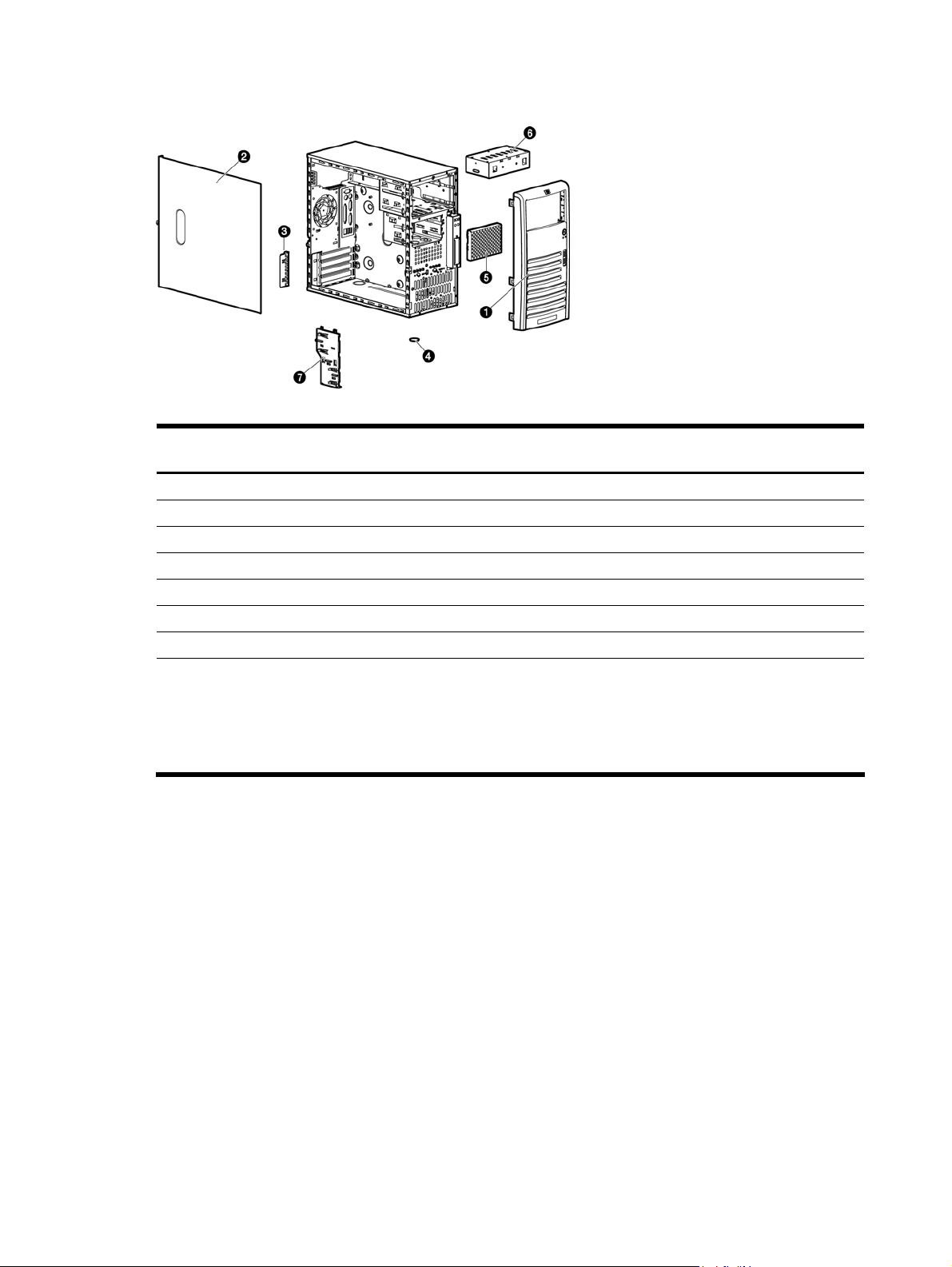
Mechanical parts exploded view
Figure -1 [Mechanical parts exploded view]
Table -1 Mechanical spare parts list
Item Description
1 Front bezel 391980-001 392174-001 Mandatory
2 Access panel 396648-001 397120-001 Mandatory
3 Expansion slot cover lock (included in Misc Hardware Kit) 397084-001 ---- Mandatory
4 Foot (included in Misc Hardware Kit) 166939-007 ---- Mandatory
5 Hard drive EMI shield 395015-001 395624-001 Mandatory
6 Optical drive shield 395019-001 395625-001 Mandatory
7 Drive release latch 395020-001 397122-001 Mandatory
8 Misc Plastics/Hardware Kit *, including:
Assembly
number
---- 397119-001 Mandatory
Spare part
number
Customer
self repair
• Screw, 6-32x.187,TF,HI/TP w/serr (10)
• Screw, M3,TT,HI/TP,S15IPX5mm (10)
• Feet (4)
• Expansion slot cover lock
• Thumbscrew, 6-32 X .25, Cbn
4
Page 7
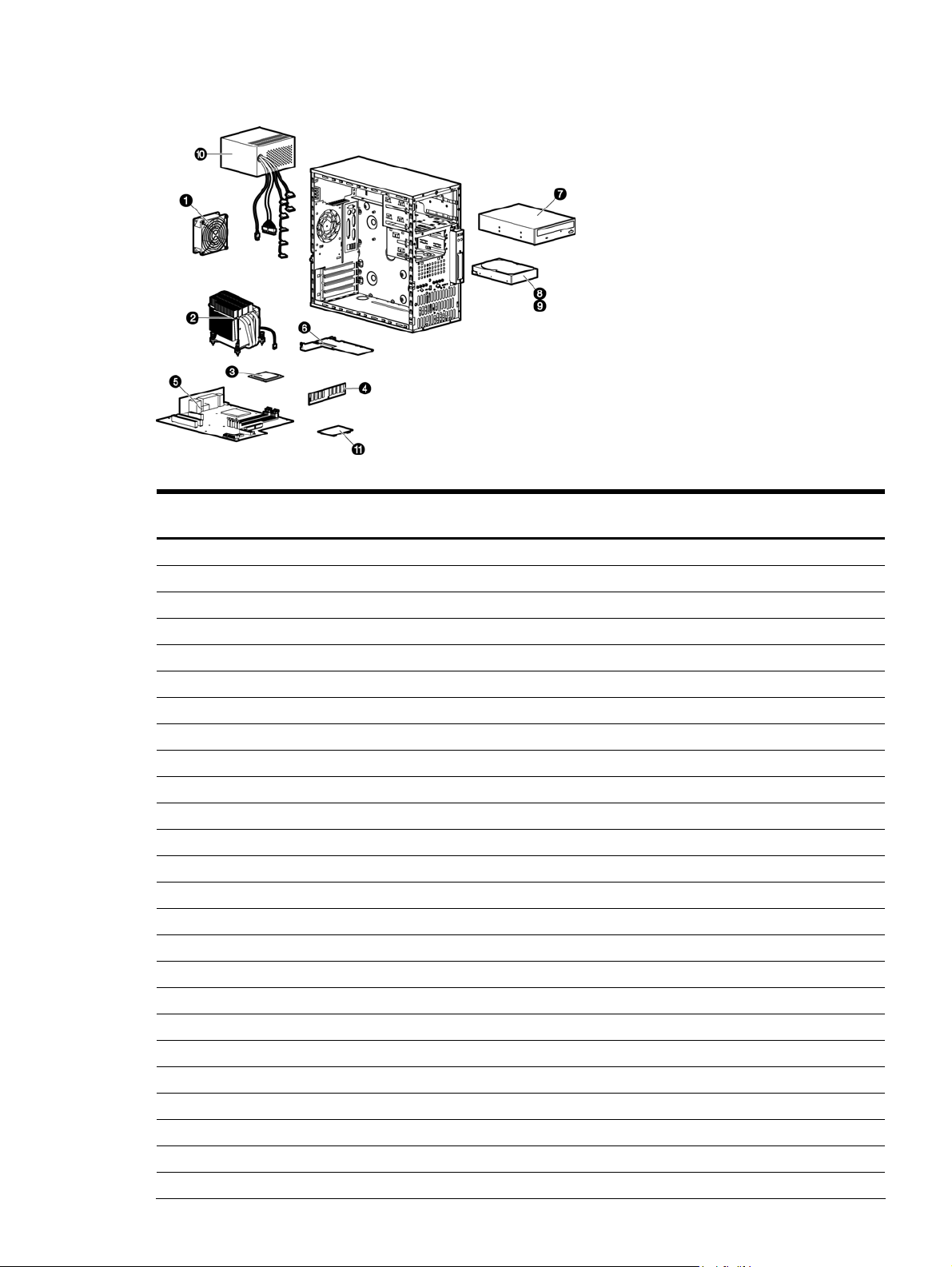
System components exploded view
Figure -2 [System components exploded view]
Table -2 System components spare parts list
Item Description
1 System fan 391976-001 392172-001 Mandatory
2 Processor heatsink-cooling fan (HSF) assembly 391818-001 392171-001 Recommended
3 Processors (include alcohol pad and thermal grease)
a) Intel Celeron D 2.53 GHz/533 MHz FSB with 256 KB L2 cache 367744-005 392167-001 Recommended
b) Intel Pentium 4 3.0 GHz/800 MHz FSB with 2 MB L2 cache 379289-001 392168-001 Recommended
c) Intel Pentium 4 3.2 GHz/800 MHz FSB with 2 MB L2 cache 379289-002 392169-001 Recommended
d) Intel Pentium 4 3.4-GHz/800 MHz FSB, with 2 MB L2 cache 379289-003 398388-001 Recommended
e) Intel Pentium 4 3.6-GHz/800 MHz FSB, with 2 MB L2 cache 379288-001 398389-001 Recommended
f) Intel Pentium 4 3.8-GHz/800 MHz FSB, with 2 MB L2 cache 379288-002 398390-001 Recommended
4 Memory boards (PC2-4200 unbuffered ECC DDR II DIMM )
a) 512 MB 384375-051 392176-001 Mandatory
b) 1 GB 384376-051 398955-001 Mandatory
c) 2 GB 384377-061 398956-001 Mandatory
5 System board 389504-001 392170-001 Recommended
6 SCSI controller card 332541-001 339051-001 Recommended
366651-001 Mandatory
Mass storage devices
7 48X CD-ROM drive 266072-001 288894-001 Mandatory
8 SCSI hard drive
a) 36GB 15K U320 357014-001 372659-001 Mandatory
b) 72GB 10K U320 332934-001 Mandatory
c) 146GB 10K U320 357915-001 Mandatory
9 SATA hard drive 332649-003 373311-001 Mandatory
Misc parts
10 350-W power supply unit with cable assembly 391977-001 392173-001 Mandatory
Assembly
number
Spare part
number
Customer self
repair
5
Page 8

Table -2 System components spare parts list
Item Description
11 HP Lights-Out 100 Remote Management Card * 389503-001 392175-001 Mandatory
12 Hard drive conversion bracket * 351795-001 397117-001 Mandatory
13 Return kit * ---- 394742-001 Mandatory
14 CD-ROM drive cable assembly, ATA100 * 395016-001 395620-001 Mandatory
15 SCSI hard drive cable * 391982-001 392178-001 Mandatory
16 SATA hard drive cable, 5.25-inch, ODD bay * 326965-002 346142-001 Mandatory
17 SATA hard drive cable * 381868-002 392179-001 Mandatory
18 USB/Power LED cable* 398417-001 398770-001 Mandatory
HP contact information
For the name of the nearest HP authorized reseller:
• In the United States, call 1-800-345-1518.
• In Canada, call 1-800-263-5868.
• In other locations, refer to the HP website at http://www.hp.com/.
For HP technical support:
• In North America:
• Call 1-800-HP-INVENT (1-800-474-6836). This service is available 24 hours a day, 7 days a week.
For continuous quality improvement, calls may be recorded or monitored.
• If you have purchased a Care Pack (service upgrade), call 1-800-633-3600. For more information
about Care Packs, refer to the HP website at http://www.hp.com/.
• Outside North America, call the nearest HP Technical Support Phone Center. For telephone numbers for
worldwide Technical Support Centers, refer to the HP website at http://www.hp.com/
Assembly
number
Spare part
number
.
Customer self
repair
Before you contact HP
Be sure to have the following information available before you call HP:
• Technical support registration number (if applicable)
• Product serial number
• Product model name and number
• Applicable error messages
• Add-on boards or hardware
• Third-party hardware or software
• Operating system type and revision level
6
Page 9
2 Removal and replacement procedures
This chapter provides subassembly/module-level removal and replacement procedures for the HP ProLiant ML110
Generation 3 server.
Review the specifications of a new component before installing it to make sure it is compatible with the server.
When you integrate new components into the system, record its model and serial number, and any other
pertinent information for future reference. After completing any removal or replacement procedure, run the
diagnostics program to verify that all components operate properly.
Hardware configuration tools
In performing any hardware configuration procedure you may need the following tools:
• T-15 Torx screwdriver
• Flat-blade screwdriver
NOTE: The figures used in this chapter to illustrate procedural steps are labeled numerically (i.e., 1, 2…).
When these figures are used in substep items, the alphabetically labeled instructions correspond to the
numbered labels on the related figure (i.e., Label 1 corresponds to step a, label 2 corresponds to step b, etc.).
Hardware configuration information
WARNING! Only authorized technicians trained by HP should attempt to repair this equipment. Because of the
complexity of the individual boards and subassemblies, no one should attempt to make repairs at the
component level or to make modifications to any printed wiring board. Improper repairs can create a safety
hazard.
CAUTION: Electrostatic discharge (ESD) can damage electronic components. Be sure that you are properly
grounded (earthed) before beginning any installation procedure. Refer to the “Electrostatic Discharge
Information” section for more information.
Before removing any serviceable parts, determine whether the part is hot-plug or non-hot-plug.
Non-hot-plug device
If the device is non-hot-plug, you must power down the server. Non-hot-plug devices in the server include the
processor, all boards, memory modules, fans, PCI option cards, and all hard drives.
Electrostatic discharge information
ESD can damage static-sensitive devices or microcircuitry. Proper packaging and grounding techniques are
necessary precautions to prevent damage. To prevent electrostatic damage, observe the following precautions:
• Transport products in static-safe containers such as conductive tubes, bags, or boxes.
• Keep electrostatic-sensitive parts in their containers until they arrive at static-free stations.
• Cover workstations with approved static-dissipating material. Use a wrist strap connected to the work
surface and properly grounded (earthed) tools and equipment.
• Keep work area free of nonconductive materials, such as ordinary plastic assembly aids and foam packing.
• Make sure that you are always properly grounded (earthed) when touching a static-sensitive component or
assembly.
• Avoid touching pins, leads, or circuitry.
• Always place drives with the Printed Circuit Board (PCB) assembly-side down.
• Use conductive field service tools.
7
Page 10
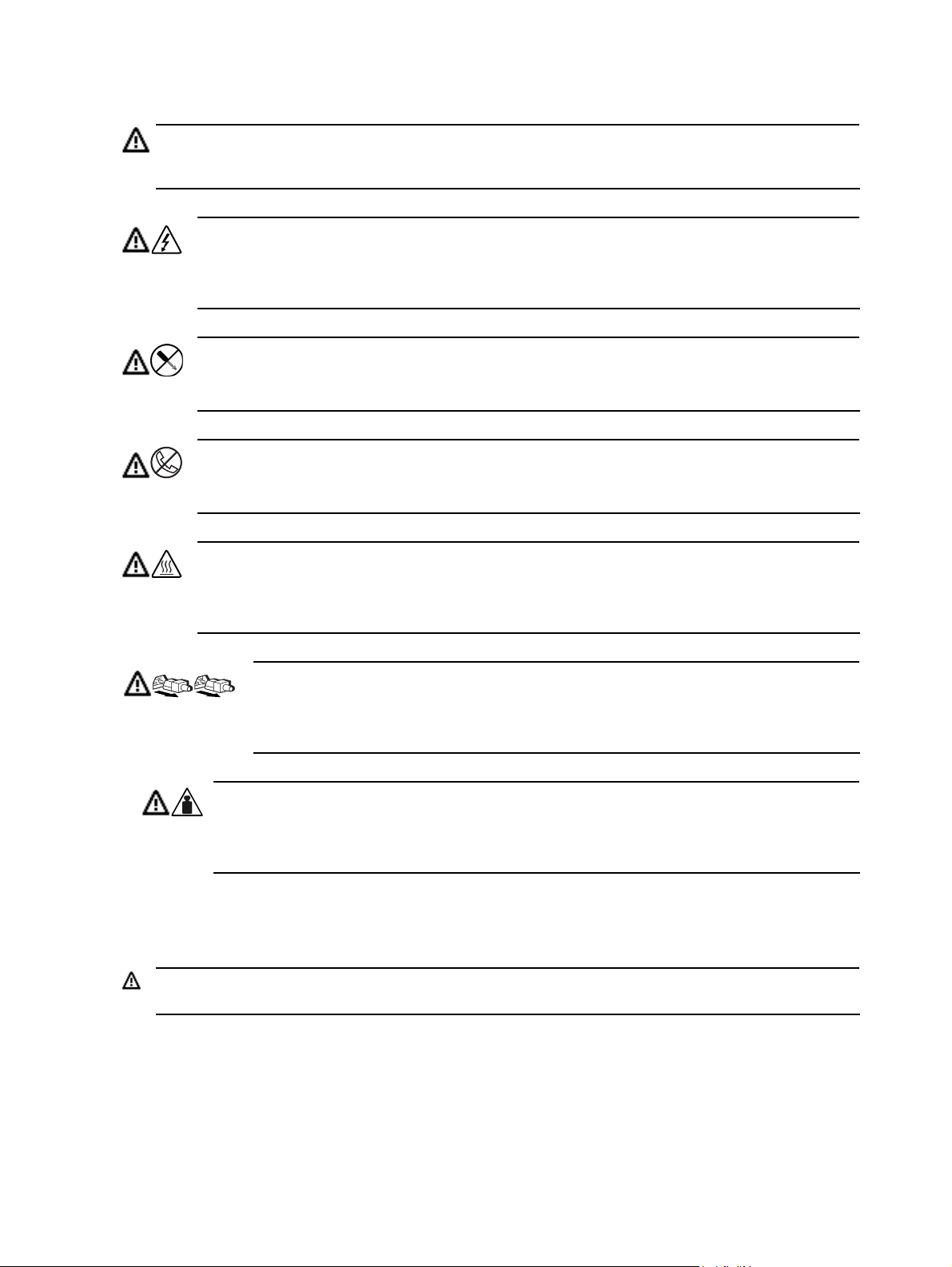
Symbols on equipment
These symbols may be located on equipment in areas where hazardous conditions may exist.
WARNING! This symbol, in conjunction with any of the following symbols, indicates the presence of a
potential hazard. The potential for injury exists if warnings are not observed. Consult your documentation for
specific details.
This symbol indicates the presence of hazardous energy circuits or electric shock hazards. Refer all
servicing to qualified personnel.
WARNING! To reduce the risk of injury from electric shock hazards, do not open this enclosure. Refer
all maintenance, upgrades, and servicing to qualified personnel.
This symbol indicates the presence of electric shock hazards. The area contains no user or field
serviceable parts. Do not open for any reason.
WARNING! To reduce the risk of injury from electric shock hazards, do not open this enclosure.
This symbol on an RJ-45 receptacle indicates a network interface connection.
WARNING! To reduce the risk of electric shock, fire, or damage to the equipment, do not plug
telephone or telecommunications connectors into this receptacle.
This symbol indicates the presence of a hot surface or hot component. If this surface is contacted, the
potential for injury exists.
WARNING! To reduce the risk of injury from a hot component, allow the surface to cool before
touching.
These symbols, on power supplies or systems, indicate that the equipment is supplied by
multiple sources of power.
WARNING! To reduce the risk of injury from electric shock, remove all power cords to
completely disconnect power from the system.
This symbol indicates that the component exceeds the recommended weight for one individual to
Weight in kg
Weight in lbs
handle safely.
WARNING! To reduce the risk of personal injury or damage to the equipment, observe local
occupational health and safety requirements and guidelines for manual material handling.
Pre-installation instructions
Perform the steps below before you open the server or before you remove or replace any component:
WARNING! Failure to properly turn off the server before you open it or before you start installing/removing
components may cause serious damage as well as bodily harm.
1. Turn off the server and all the peripherals connected to it.
Refer to the Powering down the server section in this chapter for detailed instructions on how to completely
power down the server.
2. Unplug all cables from power outlets to avoid exposure to high energy levels that may cause burns if parts
are short-circuited by metal objects such as tools or jewelry. If necessary, label each cable for reassembly.
3. Disconnect telecommunication cables to avoid exposure to shock hazard from ringing voltages.
4. Open the server according to the instructions described in the System covers section in this chapter.
8
Page 11

5. Follow the ESD precautions listed previously in this chapter when handling a server component.
Post-installation instructions
Observe the following items after installing or removing a server component:
1. Make sure that you install all components according to the described step-by-step instructions.
2. Make sure not to leave loose tools or parts inside the server.
3. Reinstall any expansion board(s), peripheral(s), and system cable(s) that have previously been removed.
4. Reinstall the system covers.
5. Connect all external cables and the AC power cord to the system.
6. Press the power button on the front panel to turn on the server.
CAUTION: Do not operate the server for more than 10 minutes with the access panel and drives removed.
Otherwise, improper cooling airflow may damage system components.
Powering down the server
To completely remove all power from the system, disconnect all power cords from the server.
WARNING! Hazardous voltages are present inside the server. Always disconnect AC power from the server
and other associated assemblies while working inside the unit. Serious injury may result if this warning is not
observed.
WARNING! To reduce the risk of injury from electric shock, disconnect all power cords to completely remove
power from the system.
WARNING! To reduce the risk of personal injury from hot surfaces, allow the internal system components to
cool before touching them.
CAUTION: Protect the server from power fluctuations and temporary interruptions with a regulating
uninterruptible power supply (UPS). This device protects the hardware from damage caused by power surges
and voltage spikes, and keeps the system in operation during a power failure.
CAUTION: The server must always be operated with the system covers on. Proper cooling is not achieved
when the system covers are removed.
To power down the server:
1. Shut down server as directed by the operating system documentation.
2. Disconnect the AC power cord from the AC outlet and then from the server.
3. Be sure that the power LED indicator is turned off and that the fan noise has stopped.
4. Disconnect all external peripheral devices from the server.
9
Page 12
System covers
The access panel and the front bezel are both detachable. You must remove these system covers before you can
remove or replace a server component.
Access panel
You must remove the access panel to access internal components and mass storage devices.
To remove the access panel:
1. Perform steps 1 through 3 of the Pre-installation instructions.
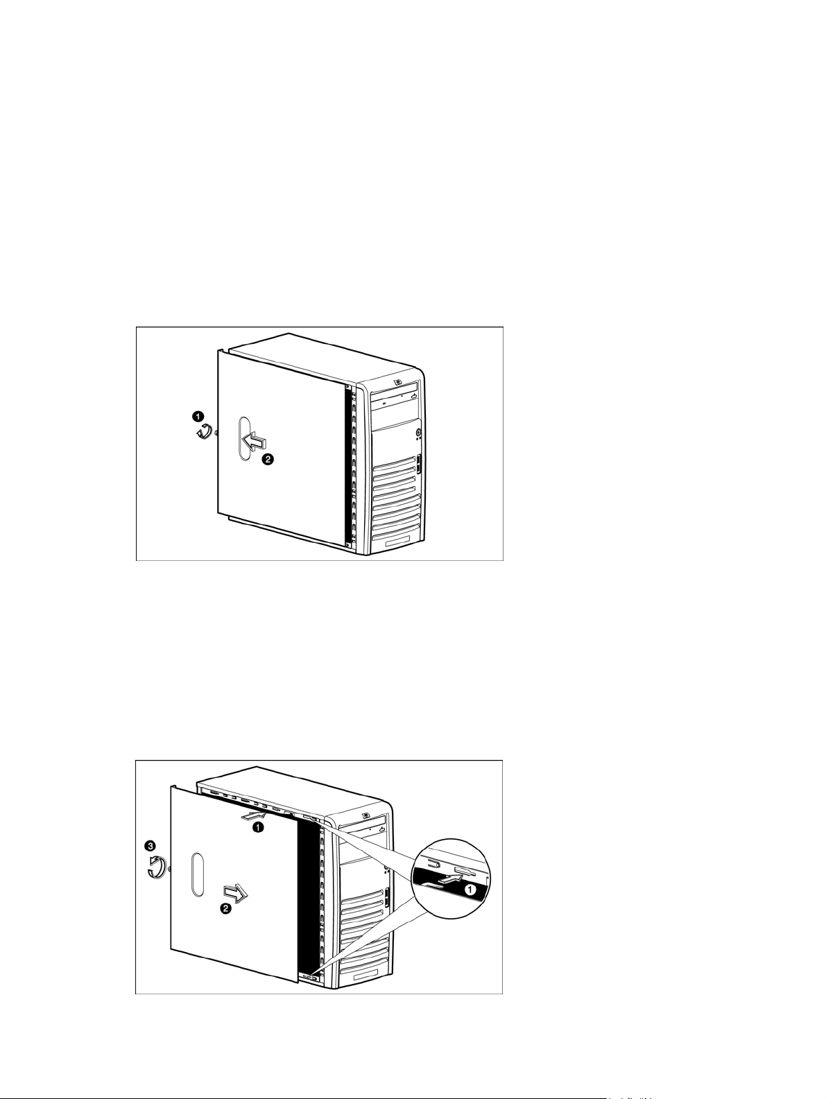
2. Remove the access panel from the chassis:
a. Loosen the captive thumbscrew located on the rear edge of the access panel.
b. Slide the panel back about 2.5 cm (1.0 in).
c. Lift the panel from the chassis.
Figure -1 [Removing the access panel]
3. Place the access panel in a safe place for reinstallation later.
After completing any removal or replacement procedure, replace the access panel by following the steps below:
1. Perform steps 1 through 3 of the Post-installation instructions.
2. Reinstall the access panel:
a. Use two hands to place the access panel flat against the chassis, the back of the access panel
extending about 2.5 cm (1.0 in) behind the back of the server. Make sure the hooks on the access
panel align with the holes on the edges of the chassis.
b. Slide the access panel toward the front of the chassis to position it into place.
c. Tighten the captive thumbscrew to secure the access panel.
Figure -2 [Reinstalling the access panel]
3. Perform steps 5 through 6 of the Post-installation instructions.
10
Page 13
Front bezel
You must remove the front bezel to access the hard drives and optical drives.
To remove the front bezel:
1. Remove the access panel.
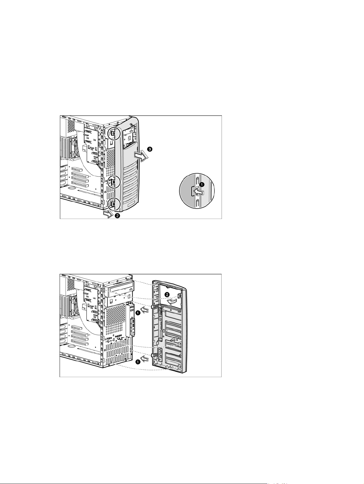
2. Remove the front bezel:
Figure -3 [Removing the front bezel]
a. Press in on the two bottom tabs on the side of the bezel so that they release from the chassis.
b. Press in on the upper tab on the side of the bezel so that it releases from the chassis. The bezel will
rotate out slightly.
c. Pull the bezel away from the front panel.
3. Place the front bezel in a safe place for reinstallation later.
To replace the front bezel, follow the steps below:
1. Position the chassis in the upright position.
2. Insert the two hooks on the right side of the bezel into the rectangular holes on the chassis, and then rotate
the bezel into place so that the three tabs on the left side of the bezel snap into the slots on the chassis.
Figure -4 [Reinstalling the front bezel]
11
Page 14
Drives
You can install up to two optical drives or up to three hard drives in the server. The second optical drive bay can
support a SATA or SCSI hard drive.
Cable management
Always follow good cable management practices when working inside the computer.
• Keep cables away from major heat sources like the heatsink.
• Do not jam cables on top of expansion cards or memory modules. Printed circuit cards are not designed to
withstand excessive pressure.
• Keep cables clear of sliding or moveable parts to prevent cutting or crimping.
• When folding a flat ribbon cable, never fold to a sharp crease. Sharp creases may damage the wires.
• Some flat ribbon cables come prefolded. Never change the folds on these cables.
• Do not sharply bend any cable. A sharp bend can break the internal wires.
• Never bend a SATA data cable tighter than a 30 mm (1.18 in) radius.
• Never crease a SATA data cable.
• Do not rely on components like the drive cage, power supply, or system cover to push cables down into the
chassis.
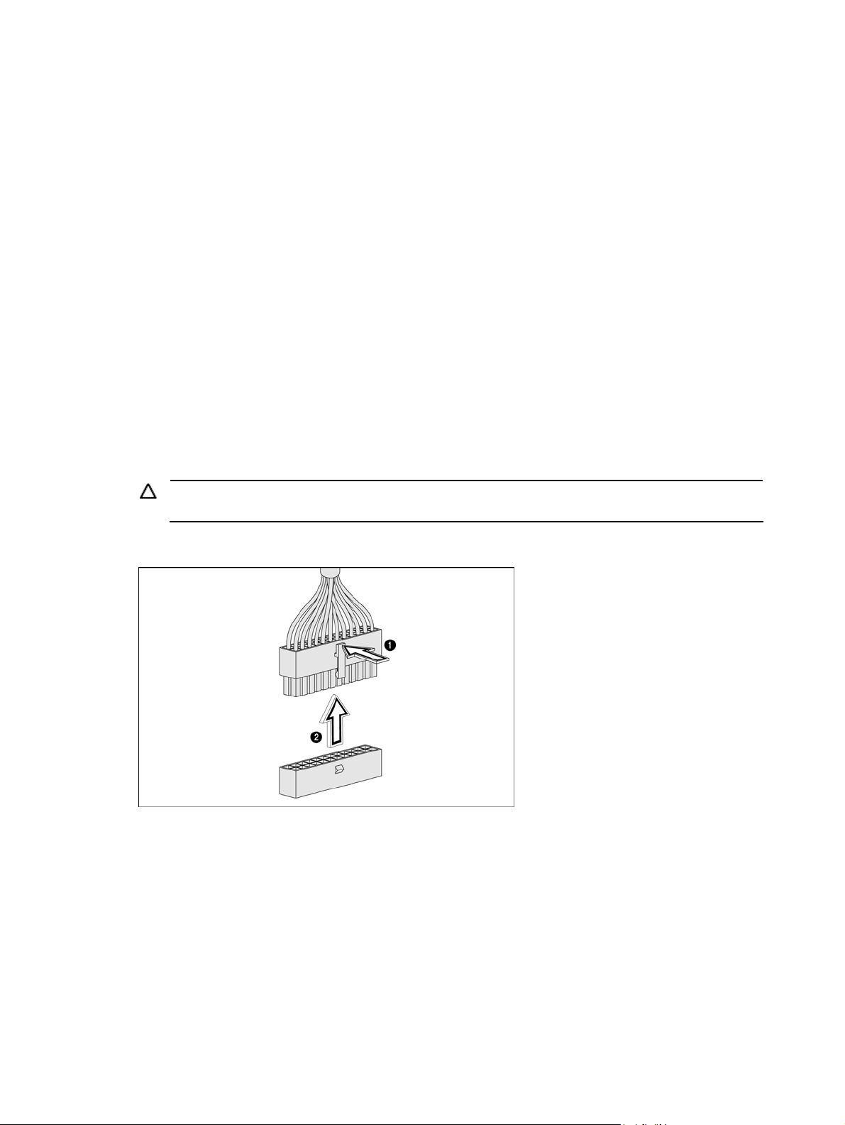
When removing the power supply power cables from the P2 or P3 connectors on the system board, always
follow these steps:
1. Squeeze on the top of the retaining latch attached to the cable end of the connector.
2. Grasp the cable end of the connector and pull it straight up.
CAUTION: Always pull the connector - NEVER pull on the cable. Pulling on the cable could damage the
cable and result in a failed power supply.
Figure -5 [Unplugging power cables]
12
Page 15

Cable connections
The following table provides information about power supply cable connector labels, as well as system board
connector designators. The top half of the table indicates the label on the power supply cable. The bottom half of
the table provides the system board designators that various cables plug into. For more detailed information
about system board components, see System board components in Chapter 4.
Table -1 Cable connections
Cable To Cable Designator
Power supply System board P1
Power supply System board CPU power P2
Power supply 1st SATA hard drive P9
Power supply 2nd SATA hard drive P8
Power supply 3rd SATA hard drive P7
Power supply 1st SCSI hard drive P6
Power supply 2nd SCSI hard drive P5
Power supply 3rd SCSI hard drive P4
Power supply 1st optical drive P3
Power supply 2nd optical drive P4
Cable To System board designator
CPU fan connector System board P70
Rear system fan System board P8
Serial port B System board P52
Front USB connector System board P24
Front I/O connector System board P5
1st SATA connector System board P60
2nd SATA connector System board P61
Internal USB tape drive System board J4
Internal USB port System board J3
13
Page 16
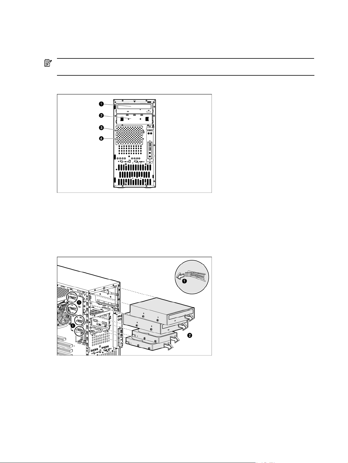
Drive bay configuration
The server supports a maximum of four internal drives. The two upper drive bays are primarily for removable
media devices, while the two lower drive bays are only for hard drives. The two upper bays are half height IDE
optical bays. The two lower drive bays can accommodate non-hot-plug hard drives.
NOTE: You can install a SATA or SCSI hard drive into the second half-height optical bay. This type of
installation requires use of a conversion kit.
Figure -6 [Drive bay configuration]
1 Optical drive 3 2
nd
2 2
optical drive or 3rd SATA or SCSI hard drive 4 1st SATA or SCSI hard drive
Releasing drives
A drive latch with release tabs secures the drives in the drive bay. Lift the release tab on the drive latch for the
drive you want to remove, and then slide the drive from its drive bay.
Figure -7 [Releasing drives]
When replacing drives, remove the four guide screws (two on each side) from the old drive. You will need these
screws to install a new drive.
nd
SATA or SCSI hard drive
14
Page 17
Optical drive
To replace an optical drive:
1. Perform steps 1 through 3 of the Pre-installation instructions.
2. Remove the access panel.
3. Remove the front bezel.
4. Remove the optical drive from the server:
a. Disconnect the power and data cables from the rear of the optical drive.
b. A drive latch with release tabs secures the drives in the drive bay. Lift the release tab on the drive latch.
c. Slide the drive from the drive bay.
Figure -8 [Removing an optical drive]
5. Place the old optical drive on a static-dissipating work surface or inside of an anti-static bag.
6. Remove the new optical drive from its protective packaging.
7. Check that the IDE jumper on the rear section of the optical drive is set to Cable-Select mode.
8. Install the new optical drive:
a. Insert four screws (two on each side) into the new optical drive.
b. Guide the new optical drive into the optical bay, with the cable connectors facing the rear of the
chassis, and then push the drive all the way into the drive bay until the drive clicks into place.
c. Connect the IDE power and data cables to their connectors on the rear of the drive.
Figure -9 [Installing an optical drive]
9. Observe the post-installation procedures.
15
Page 18

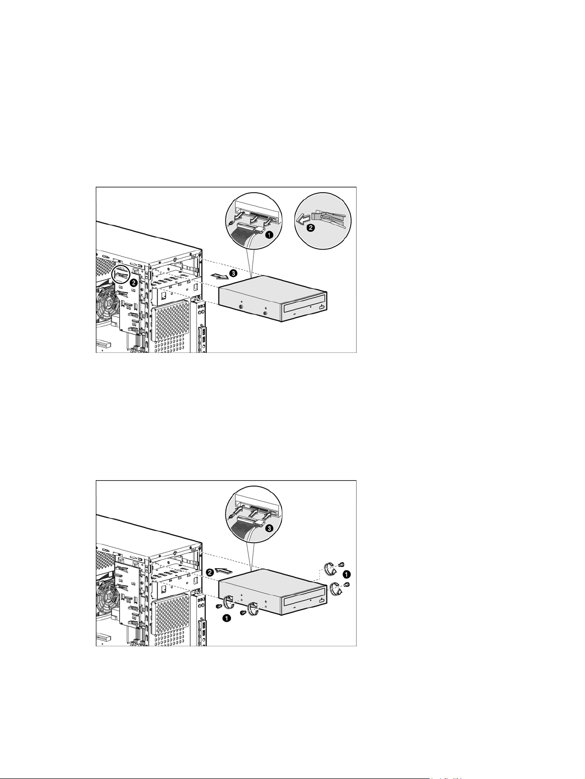
Optional media device
The lower half-height drive bay may be used for an optical drive or a non-hot-plug SATA or SCSI hard drive. For
more information about installing a hard drive in this bay, see Hard drive bracket later in this chapter.
To install an optional optical drive:
1. Perform steps 1 through 3 of the Pre-installation instructions.
2. Remove the access panel.
3. Remove the front bezel.
4. Remove the drive shield to prepare the bay for drive installation:
a. Remove the screw that secures the drive shield.
b. Pull the shield off of the chassis. Store it for later use.
CAUTION: Do not discard the shield. If the drive is removed in the future, you must reinstall the shield
to maintain proper system function.
Figure -10 [Removing the drive shield]
5. Prepare the new drive for installation. Refer to the documentation that came with the drive for related
installation procedures.
6. Install the new drive:
a. Insert four screws (two on each side) into the new optical drive.
b. Guide the new drive into the bay, with the cable connectors of the drive facing the rear of the chassis,
and then push the drive all the way into the chassis until the drive clicks into place.
c. Connect the power and data cables to the connectors on the rear of the drive.
Figure -11 [Installing an optional media drive]
7. Observe the post-installation procedures.
16
Page 19

Hard drives
You can install either SATA hard drives or SCSI hard drives in the server. The bottom two bays (bays 3 and 4)
are the hard drive bays. You can also install a SATA or SCSI hard drive into the second optical drive bay
(bay 2).
SCSI hard drives require that you also install a SCSI PCI expansion card. Connect the hard drive data cable from
the hard drive to the SCSI expansion card. Then connect power cable from the power supply to the back of hard
drive. For more information about installing PCI expansion cards, see Expansion cards.
To replace or install hard drives:
1. Perform steps 1 through 3 of the Pre-installation instructions.
2. Remove the access panel.
3. Remove the front bezel.
4. If you want to install the new hard drive in an occupied drive bay:
a. Disconnect the power and data cables from the back of the installed drive.
b. Remove the installed drive by lifting the drive latch and sliding the drive out of the bay.
c. Remove the four screws from the sides of the drive. You will reuse these screws when you install the
Figure -12 [Removing a hard drive]
new hard drive.
5. If you want to install a new hard drive in an empty drive bay, remove four screws from the front of the
chassis labeled ‘HDD SCREWS’. See Figure -13 for the location of these spare screws.
Figure -13 [Drive screw location]
17
Page 20

6. Install the new hard drive into the bay:
a. Insert the four drive screws (two on each side) into the hard drive.
b. Slide the new hard drive into the selected bay until it clicks into place.
c. If you are installing a SATA hard drive, connect the data and power cables from the system board to
the back of the hard drive and connect the power cable from the power supply to the back of the hard
drive.
d. If you are installing a SCSI hard drive, connect the data cable from the SCSI PCI expansion card to the
back of the hard drive, and then connect the power cable from the power supply to the back of the
hard drive.
Figure -14 [Installing a hard drive]
7. Observe the post-installation procedures.
Hard drive bracket - second optical drive bay
You can install a hard drive in the second optical drive bay. To install a hard drive into this bay, you first must
insert the hard drive to the hard drive conversion kit. After installing the hard drive into the conversion kit, you
can install it into the second optical bay.
To insert a hard drive into the hard drive conversion kit:
1. Insert the hard drive into the conversion kit bracket, making sure the screw holes in the bracket align with
the holes in the hard drive.
2. Insert four screws (two on each side) into the hard drive assembly, making sure the screws secure the hard
drive to the bracket.
Figure -15 [Installing a hard drive into the half-height bay bracket]
18
Page 21

To install the hard drive assembly into the second optical drive bay:
1. Remove the drive shield from the front of the second optical drive bay to prepare the bay for drive
installation:
a. Remove the screw that secures the drive shield.
b. Pull the shield off of the chassis. Store it for later use.
NOTE: Do not discard the shield. If the drive is removed in the future, you must reinstall the shield to
maintain proper system function.
Figure -16 [Removing the optical drive shield]
2. Insert four screws (two on each side) into the hard drive bracket. These screws secure the hard drive
assembly in the server after you install the drive assembly.
3. Slide the hard drive assembly into the bay until it clicks into place.
4. Connect the data and power cables to the back of the hard drive.
NOTE: If you are installing a SCSI hard drive, use the cable that comes with the server.
Figure -17 [Installing the hard drive assembly into the second optical drive bay]
5. Replace the front bezel.
6. Replace the access panel.
7. Observe the post-installation procedures.
19
Page 22

Drive latch
You can remove the latch that secures and allows removal of the drives.
To replace the drive latch:
1. Perform steps 1 through 3 of the Pre-installation instructions.
2. Remove the access panel.
3. Remove the front bezel.
4. Remove the drive latch:
Figure -18 [Removing the drive latch]
a. Pull the latch to loosen the two tabs that secure the latch to the chassis.
b. Slide the latch straight down and remove it from the chassis.
NOTE: To loosen the latch, you may also have to pull the tabs that secure inserted drives. Drive latch
tabs may break during removal.
5. Install a new drive latch:
a. Insert the two tabs on the top of the latch into their holders near the top of the chassis.
b. Slide the latch upward until the two tabs in the middle of the latch click into place.
Figure -19 [Installing a drive latch]
6. Observe the post-installation procedures.
20
Page 23

System board components
Refer to the following sections for instructions about how to remove or replace the processor, the memory
modules, the expansion cards, and the system battery.
Processor
The LGA775 processor socket supports Intel Pentium 4, Pentium D, and Celeron D processors.
Figure -20 [LGA775 processor socket]
WARNING! To reduce the risk of injury from a hot component, allow the surface to cool before touching.
To replace the processor:
1. Perform steps 1 through 3 of the Pre-installation instructions.
2. Remove the access panel.
3. Lay the server on its side with the open side facing up.
4. If necessary, remove any accessory boards or cables that prevent access to the processor socket.
5. Remove the heatsink-cooling fan (HSF) assembly:
a. Disconnect the processor fan cable from the connector on the system board (P70).
b. Twist the mounting pins counterclockwise to loosen them.
c. After you loosen all four mounting pins, lift the HSF away from the system board.
Place the HSF down in an upright position with the thermal patch facing upward. Do not let the thermal
patch touch the work surface.
Figure -21 [Removing the heatsink-cooling fan assembly]
21
Page 24

6. Remove the processor:
a. Disengage the load lever.
b. Lift the retention plate to expose the socket body.
c. Grasp the processor by its edges and lift it out of the socket.
Figure -22 [Removing the processor]
7. Place the processor on a static-dissipating work surface or in an anti-static bag.
To allow the heatsink to draw as much heat as possible from the processor base, there must be good
contact between the heatsink base and the top of the processor. To ensure good contact, you must apply
thermal grease compound.
8. Apply the thermal grease compound:
a. Use a clean cloth dipped in rubbing alcohol to clean the contact surface on the HSF and on the new
processor. Wipe the contact surfaces several times to make sure they are free of particles or dust
contaminants.
CAUTION: Never touch the bottom size of the processor; any contaminant could prevent the
processor contact pads from making contact with the socket.
b. Apply the thermal grease compound to both contact surfaces.
c. Use a proper tool to spread the grease throughout the entire contact surface and lightly scrape off any
excess grease.
CAUTION: Applying too much grease creates a gap between the contact surfaces, significantly
reducing the ability of the heatsink to draw out heat. Installing the heatsink with excessive grease can
also cause the grease to spread over the processor pins or the system board base, which can cause
electrical shorts that damage the system.
9. Install the new processor:
a. With the load lever and the retention plate disengaged, hold the processor by its edges and align it
over the empty processor socket. Make sure that you properly align the processor with the orientation
notch on the socket.
b. Insert the processor into the socket.
c. Engage the retention plate and the load lever.
22
Page 25

Figure -23 [Installing a processor]
After you install the processor, you must reinstall the HSF on top of the processor socket. The thermal grease you
applied on the contact surfaces of the HSF and the processor provides the necessary thermal bonding to allow
the heatsink to draw heat from the processor.
CAUTION: To prevent processor overheating or system instability, use only an HSF assembly specified for the
HP ProLiant ML110 Generation 3 server.
10. Replace the heatsink-cooling fan assembly:
a. Properly align the HSF mounting pins to the system board mounting holes and press down until you
hear a click.
b. Twist the mounting pins clockwise to secure the HSF connection to the system board.
c. Connect the processor fan cable to the connector on the system board (P70).
CAUTION: Failure to connect the processor fan cable to the system board may result in damage to the
processor and could cause the server to shut down without displaying messages.
Figure -24 [Installing the heatsink-cooling fan assembly]
11. Observe the post-installation procedures.
23
Page 26

Memory
The HP ProLiant ML110 Generation 3 server has four DIMM slots that support up to 8 GB maximum system
memory (2 GB in each of the four DIMM slots).
Figure -25 [DIMM slots]
Guidelines for installing memory modules
You must adhere to the following guidelines when adding or replacing memory modules:
• Use PC2-4200 unbuffered ECC DDRII DIMMs.
• DIMM sizes supported are 512 MB, 1 GB, and 2 GB, allowing up to a total of 8 GB maximum system
memory capacity.
• Supported DIMM configurations are single DIMM, one pair (two DIMMs), or two pairs (4 DIMMs).
• For optimal two-DIMM configuration, populate slot 1 and slot 3. Identical DIMMs are recommended.
To remove a memory module:
1. Perform steps 1 through 3 of the Pre-installation instructions.
2. Remove the access panel.
3. Lay the server on its side with the open side facing up.
4. If necessary, remove any accessory boards or cables that prevent access to the memory slots.
5. Locate and remove the memory module:
a. Disengage the latch socket at both ends of the DIMM sockets.
b. Gently pull the memory module upward to remove it from the socket.
Figure -26 [Removing a memory module]
6. Place the memory module on a static-dissipating work surface or inside of an anti-static bag.
To install a memory module:
a. Locate an empty memory socket on the system board.
b. Remove the memory module from its protective packaging, handling only the edges of the module.
24
Page 27

7. Install the memory module:
a. Orient the module so that the notch on the bottom edge of the module aligns with the keyed surface of
the DIMM socket, and then press it fully into the socket.
The memory sockets are structured to ensure proper installation. If you insert a memory module but it
does not fit easily into the socket, you may have inserted it incorrectly. Double-check the orientation of
the module and reinsert.
b. Firmly press the latches inward to secure the memory module in place.
If the latches do not close, the module is not inserted correctly.
Figure -27 [Installing a memory module]
8. Observe the post-installation procedures.
Expansion cards
You must remove the PCI expansion slot cover lock before installing or removing expansion cards.
The server supports the following:
• Two 32-bit/33-MHz 3.3V PCI slots (J20 to J21)
• One PCI-Express x4 link with x4 slot (J33)
• One PCI Express x8 link with x16 slot (J32)
Figure -28 [PCI slot location]
To install an expansion card:
1. Perform steps 1 through 3 of the Pre-installation instructions.
2. Remove the access panel.
3. If necessary, remove any accessory boards or cables that prevent access to the PCI slots.
4. Remove the PCI slot cover lock from the rear of the server to gain access to the expansion slots:
a. Remove the retaining screw that secures the lock to the chassis.
b. Remove the slot cover lock from the chassis.
25
Page 28

Figure -29 [Removing the PCI slot cover lock]
5. Lay the server on its side with the open side facing up.
If replacing a PCI expansion card go to step 6.
If installing a PCI expansion card for the first time, skip to step 8.
6. When removing an expansion card from an expansion slot, hold the card at both ends, and then carefully
rock the card back and forth until the expansion cards pull free from the slot.
7. Remove the card from the chassis. Store the old card in the anti-static packaging.
8. If a PCI expansion slot has a slot cover, remove it prior to installation the card.
CAUTION: Do not discard the slot cover. If the PCI expansion card is removed in the future, the slot
cover must be reinstalled to maintain proper cooling.
9. When installing an expansion card, hold the card just above the expansion slot on the system board, and
then move the card toward the rear of the chassis so that the bracket on the card is aligned with the open
slot on the rear of the chassis.
10. Press the card straight down into the expansion slot on the system board.
Figure -30 [Installing a PCI card]
11. Replace the slot cover lock by sliding it onto the rails toward the server.
12. Replace the slot cover lock retaining screw.
26
Page 29

Figure -31 [Replacing the PCI slot cover]
13. Connect any necessary cables to the card.
14. Observe the post-installation procedures.
System battery
The server uses volatile memory that requires a battery to retain system information when power is removed. This
3-volt lithium coin cell battery is located on the system board.
Figure -32 [System battery location]
If the server no longer automatically displays the correct date and time, you may need to replace the system
battery. Under normal use, battery life is five to ten years.
WARNING! Note the following reminders when replacing the system battery:
•
Replace the battery with the same type as the battery recommended by HP. Use of another battery may present a risk of
fire or explosion.
• A risk of fire and chemical burn exists if the battery is not handled properly. Do not disassemble, crush, puncture, or
short external contacts, or expose the battery to temperatures higher than 60°C (140°F).
• Do not dispose of used battery in water or fire. Dispose of used batteries according to the manufacturer's instructions.
CAUTION: Loss of BIOS settings occurs when the battery is removed. You must reconfigure BIOS settings
whenever you replace the battery.
To replace the system battery:
1. Perform steps 1 through 3 of the Pre-installation instructions.
2. Remove the access panel.
3. Lay the server on its side for better access to the battery holder (XBT2).
4. If necessary, remove any accessory boards or cables that prevent access to the battery holder.
27
Page 30

5. Replace the battery:
a. To release the battery from its holder, squeeze the metal clamp that extends above one edge of the
battery. When the battery pops up, lift it out.
b. To insert the new battery, slide one edge of the replacement battery under the holder’s lip with the
positive side up. Push the other edge down until the clamp snaps over the other edge of the battery.
Figure -33 [Replacing the battery]
6. Replace the access panel.
7. Observe the post-installation procedures.
Power supply unit (PSU)
Located on the rear panel of the server power supply is a single standard autoranging 350-watt PSU with PFC
(power factor correction) function.
WARNING! Note the following reminders are to reduce the risk of personal injury from electric shock hazards
and/or damage to the equipment.
• Installation of power supply units should be referred to individuals who are qualified to service server
systems and are trained to deal with equipment capable of generating hazardous energy levels.
• DO NOT open the power supply unit. There are no serviceable parts inside it.
To replace the power supply:
1. Perform steps 1 through 3 of the Pre-installation instructions.
2. Remove the access panel.
3. Lay the server on its side with the open side facing up.
4. Remove the power supply:
a. Disconnect the processor and system board power cables from the system board connectors
(P1 and P2).
b. Disconnect the power cables of all installed drives from the PSU.
c. Remove the four screws that secure the PSU to the chassis.
d. Lift the power supply out of the chassis.
28
Page 31

Figure -34 [Removing the PSU]
5. Install a new PSU:
a. Align the new PSU to the support edges inside of the chassis.
b. Secure the PSU to the chassis using four screws.
c. Reconnect the processor and system board power cables to the system board connectors (P1 and P2),
and then connect the power cables to all installed drives.
Figure -35 [Installing a PSU]
6. Observe the post-installation procedures.
29
Page 32

System fan
A new system fan can be installed to allow the server to operate properly in case the default system fan becomes
defective.
To replace the system fan:
1. Perform steps 1 through 3 of the Pre-installation instructions.
2. Remove the access panel.
3. Remove the system fan:
WARNING! Be sure to support the system fan with your hand when removing screws from the chassis.
The fan could fall onto the system board or an accessory board causing damage if not supported.
a. Disconnect the system fan cable from its connector (P8) on the system board.
b. Remove the four screws from the rear of the chassis that secure the fan.
c. Remove the fan from the chassis.
Figure -36 [Removing the system fan]
4. Install a new system fan:
a. Align the new fan to the screw holes inside of the chassis
b. While holding the new fan against the chassis, secure the fan to the chassis with four screws.
c. Connect the system fan cable to its connector (P8) on the system board.
Figure -37 [Installing a system fan]
5. Observe the post-installation procedures.
30
Page 33

HP Lights-Out 100 Remote Management Card
Lights-Out 100 Remote Management is a suite of products that enable remote management of ProLiant 100
Series servers. HP Lights-Out 100 allows customers or their service providers to remotely manage ProLiant ML110
G3 servers over a LAN or the Internet. With HP Lights-Out 100, users can access a system's text console, control
system power, and monitor system environmental conditions from a browser or command line.
To install the remote management card:
1. Perform steps 1 through 3 of the Pre-installation instructions.
2. Remove the access panel.
3. Lay the server on its side with the open side facing up.
4. Locate the remote management card connector on the system board.
Figure -38 [Remote management card connector location]
5. Install the remote management card in the connectors located in J110 and J111 on the system board. The
connectors are angled so that you can only install the card in one at the correct position.
Figure -39 [Installing the remote management card]
6. Observe the post-installation procedures.
31
Page 34

3 Diagnostic tools
This chapter describes the system diagnostic tools available for the HP ProLiant ML110 Generation 3 server. It
also provides a comprehensive list of POST-related messages and their meanings.
AMIBIOS software
The G3 server uses AMIBIOS to boot up the system. AMIBIOS software is a ROM BIOS-based firmware that
allows reliability, manageability, and connectivity for server platforms. This software contains a set of programs
permanently stored in an EEPROM chipset located on the system board. These programs assist in managing,
initializing, and testing the hardware devices installed on the computer.
AMIBIOS software allows you to:
• Perform configuration from the AMIBIOS Setup Utility
Using the Setup Utility, you can install, configure, and optimize the hardware devices on the system board.
In addition, you can enable various features such serial console redirection, hyper-threading, PXE boot,
IPMI Virtual Floppy support, and much more.
• Initialize hardware at bootup using POST routines
During power-on or warm reset, the BIOS performs Power-On Self Test (POST) routines to test system
components, to allocate resource for various hardware devices, and to the prepare the system to boot to
various operating systems.
Accessing the Setup Utility
1. Turn on the monitor and server. If the server is already turned on, save your data and exit all open
applications, then restart the server.
2. When the HP logo is displayed during POST, press F10. If you fail to press F10 before POST is completed,
you will need to restart the server.
The first page displayed is the Main menu showing the Setup Utility menu bar. Use the left (←) and right
(→) arrow keys to move between selections on the menu bar. Use the up (↑) and down (↓) arrow keys to
select items within a menu.
Figure -1 [Setup Utility Main menu]
32
Page 35

Navigating through the Setup Utility
Use the keys listed in the legend bar on the right of the Setup screen to navigate through the various menu and
submenu screens of the Setup Utility. Table -1 lists these legend keys and their respective functions.
Table -1 Setup Utility Navigation Keys
Key Function
← and → To move between selections on the menu bar.
↑ and ↓ To move the cursor to the field you want.
The currently selected field is highlighted. The right side of each menu screen displays a field help
panel—Item Specific Help panel. This panel displays the help text for the currently selected field. It
updates as you move the cursor to each field.
+ and - To select a value for the currently selected field (only if it is user-configurable).
Press the (+) or (-) keys repeatedly to display each possible entry, or the Enter key to choose from a
pop-up menu.
A parameter that is enclosed in square brackets [ ] is user-configurable.
Grayed-out parameters are not user-configurable for one of the following reasons:
• The field value is auto-configured or auto-detected.
• The field value is informational only.
• The field is password-protected.
Enter, Tab, ShiftTab
Esc If you press this key:
F1 To bring up the General Help window.
F9 To load default system values.
F10 To save changes and close the Setup Utility.
Figure -2 [Setup Utility General Help screen]
To select a field value or display a submenu screen.
• On one of the primary menu screens, the Exit menu displays.
• On a submenu screen, the previous screen displays.
• When you are making selections from a pop-up menu, the pop-up closes without making a selection.
The General Help window describes other Setup navigation keys that are not displayed on the legend
bar.
33
Page 36

Setup Utility primary menus
The Setup Utility menu bar displays the five primary menu selections. Table -2 lists these menus and their
corresponding functions.
Table -2 Setup Utility Primary Menus
Menu Function
Main Use this menu to:
• Set system time and date
• View BIOS version
• View BIOS build date
• View processor type
• View processor speed
• View system memory size
• View system serial number
• View MAC address for the embedded NIC
Advanced Use this menu to:
• Enable or disable hardware prefetcher.
• Enable or disable Cache Line prefetch.
• Enable or disable the support of hyper-threading technology.
• Disable SATA/IDE configuration or configure IDE/SATA to Compatible or Enhanced mode. When the
system is in Enhanced mode, you can configure the SATA as IDE, RAID, or AHCI. When the system is in
compatible mode, you can configure the IDE channels as SATA only, PATA as primary and SATA
secondary, SATA as primary and PATA as secondary, or PATA only.
NOTE: When the SATA/IDE configuration is set to Compatible mode (4 drive mode), only one SATA
drive, which acts as the Primary master, appears in the system. For example, if you set the legacy IDE
channels to SATA PRI, PATA Sec in the IDE configuration of the Setup Utility, and install two SATA drives,
one IDE hard drive, and one CD ROM drive, you will see the following:
• Primary IDE Master: [Hard Disk]
• Primary IDE Slave: [Not Detected]
• SEC IDE Master: [Hard Disk]
• SEC IDE Slave: [ATAPI CDROM]
The secondary IDE master has the IDE hard drive. There is no Primary IDE slave.
• Configure a superior device such as serial com1, serial com2, or parallel port.
• View CPU and ambient temperature.
• View CPU and chassis fan speed (RPMs).
• Enable or disable temperature display via BMC.
• View IPMI system event logging.
• Clear IPMI system event logging.
• Set IP address and subnet mask for remote access.
• Enable or disable COM1 port muxed to the remote management card.
• Enable or disable the remote management card virtual floppy,
• Enable or disable Serial over LAN (SOL) support.
NOTE: When COM1 is selected, the mux to the remote management card, you cannot use COM1 as the
BIOS serial console redirection. Use COM2 as the serial console redirection if COM1 is enabled for
remote management card muxing.
NOTE: When Serial Over LAN (SOL) is enabled, it uses virtual com3 to send data.
NOTE: All the functions above are applicable if a remote management card is installed in the server.
NOTE: The IPMI configuration menu item is not displayed on the Advanced screen if no remote
management card is inserted in the server. Configure console redirection settings to allow the system to be
displayed on a remote terminal for online server management. You can configure the baud rate from
9600 to 115200.
• Enable/disable USB legacy support. When legacy USB support is enabled, you can select either Hispeed
or Fullspeed under USB 2.0 Controller Mode if the USB 2.0 Controller is enabled.
34
Page 37

Table -2 Setup Utility Primary Menus
Menu Function
Boot Use this menu to:
• Enable or disable the BIOS summary display.
• Enable or disable the HP splash display.
• Turn on or off bootup NumLock.
• Set restore on AC power loss options, such as last state, power off, and power on.
• Set boot device priority. By default, the server searches for boot devices in the following order:
a. Removable device
b. IDE CD-ROM drive
c. Hard disk drive
d. PXE (Preboot Execution Environment, remote boot)
• View hard disk drive information.
• View network drive information.
Security Use this menu to:
• Prevent unauthorized users from accessing the system.
• Configure user access levels.
• Input asset tag ID.
For more information about this menu, please refer to the System Passwords section in this chapter.
Exit Use this menu to select an exit option from the Setup Utility. Options include:
1 Save changes and exit out of the Setup Utility
2 Discard any changes made and exit out of the Setup Utility
3 Discard any changes made and remain in the Setup Utility
4 Load optimal default CMOS configuration for the system
System Summary Screen
Figure -3 [System Summary screen]
To enable display of the System Summary Screen during bootup:
1. From the Main menu screen, select Boot.
2. Select Boot Settings Configuration.
3. Select the BIOS Summary Display field.
4. Press the plus (+) or minus (-) key to set the field to Enabled.
35
Page 38

5. Press F10 to save the changes you made and close the Setup Utility.
6. Reboot the server.
7. Press Pause/Break to freeze the screen until another key is pressed.
8. Press ESC to continue booting the system.
System passwords
The Security menu allows you to set system passwords that provide different levels of protection for the server.
There are two types of passwords:
• Supervisor password
Allows you to access and change all settings in the Setup Utility. The supervisor password allows you to
configure access for system users. The following list provides different user access levels:
• No Access – Prevents access to the Setup Utility.
• View Only – Allows access to the Setup Utility without change capability.
• Limited – Allows limited capability to change field values, such as date and time.
• Full Access – Allows capability to modify any value in the Setup Utility.
In addition, supervisor password access can protect users from booting to the operating system by setting
the Password check field to “Always”. Figure -4 shows the Security Settings screen, and that supervisor
password access allows the ability to clear user passwords and to configure so that users do not have to
enter a password to access the operating system.
• User password
Entering this password will restrict a user’s access to the Setup menus. A user can only access and modify
fields depending on the user access level set using supervisor password access.
Figure -4 [System passwords screen]
To set a system password:
NOTE: You must set a Supervisor password before defining a User password.
1. In the Security screen, select a set password field—Set User Password or Set Supervisor
Password, and then press Enter.
2. Type a new password in the Enter New Password box.
The password may consist of up to eight alphanumeric characters (A-Z, a-z, 0-9).
36
Page 39

Figure -5 [Enter New Password dialog box]
3. Retype the password to verify the first entry, and then press Enter.
4. Press F10 to save the password and close the Setup Utility.
After setting the password, Setup automatically sets the selected password field to Enabled.
To reset a system password:
• If you forget the user password or the supervisor password, the server functions normally, but you cannot
access the Setup Utility.
• If you do not know the user password but do know the supervisor password, you can use the Clear User
Password menu to clear the user password.
• If “Always” is selected in the Password check field and you do not know either the user or the supervisor
password, you cannot boot to the operating system or access the Setup Utility.
1. Perform the Pre-installation instructions listed in Chapter 2.
2. If necessary, remove any accessory boards or cables that prevent access to the CMOS button.
3. Locate the Password jumper (P137) on the system board.
4. Remove the jumper from pins 1 and 2 and power on the server.
5. Power down the server.
6. Place the jumper back on pins 1 and 2.
7. Reinstall the access panel as described in Chapter 2.
Loading system defaults
To load system default settings:
1. Reboot the server.
2. During POST, press F10 to access the Setup Utility.
3. Press F9 to load the default values.
4. Press F10 to save the changes and close the Setup Utility.
37
Page 40

Figure -6 [Load defaults screen]
Clearing CMOS
You may need to clear the Setup configuration values (CMOS) if the configuration has been corrupted, or if
incorrect settings made in the Setup Utility have caused error messages to be unreadable.
To clear CMOS:
1. Perform the pre-installation instructions listed in Chapter 2.
2. If necessary, remove any accessory boards or cables that prevent access to the system configuration switch.
3. Locate the system configuration switch (SW50) on the system board.
4. Press the switch. AC power must not be connected.
5. Perform the post-installation instructions listed in Chapter 2.
6. During POST, press F10 to access the Setup Utility.
7. Set time, date, and other system values.
8. Press F10 to save the changes you made and close the Setup Utility.
NOTE: Clearing CMOS deletes all system configurations and password settings.
Power-On Self Test (POST)
Before you can use a server, all devices must be tested and initialized, and the operating system must be
bootstrapped to the memory. This is referred to as Power–On Self–Test or POST. POST is a series of diagnostic
tests that checks firmware and hardware components on the system to ensure that the server is properly
functioning. This diagnostic function automatically runs each time the server is powered on.
These diagnostics, which reside in the BIOS ROM, isolate server-related logic failures and indicate the board or
component that you need to replace, as indicated by the error messages. Most server hardware failures will be
accurately isolated during POST. The number of tests displayed depends on the configuration of the server.
During POST you can:
• Press ESC to skip the HP logo and go to POST boot progress display system summary screen.
• Press F8 to display the Boot menu.
• Press F10 to access the Setup Utility.
• Press F12 to request a network boot (PXE).
38
Page 41

POST error indicators
When POST detects a system failure, it displays a POST error message.
Recoverable POST errors
Whenever a non-fatal error occurs during POST, an error message describing the problem appears onscreen.
These error messages are displayed in normal video (white text on black background), and show the details of
the error. The following is an example of a POST error message:
018 – CMOS Date/Time not set
Table -3 lists the most common POST error messages with corresponding troubleshooting recommendation. HP
recommends that you correct the error, even if the server appears to boot successfully.
Table -3 POST Error Messages
Error code Error Message Description/Corrective Action
000 Timer Error Indicates an error while programming the count register of
003 CMOS Battery Low CMOS Battery is low. This message usually indicates that the
004 CMOS setting Wrong CMOS settings are invalid. This error can be resolved by using
005 CMOS Checksum Bad CMOS contents failed the Checksum check. Indicates that the
008 Unlock keyboard PS2 keyboard is locked. Users need to unlock the keyboard to
009 PS2 Keyboard not found Keyboard not working. Verify that the keyboard cable is securely
018 CMOS Date/Time not Set The CMOS Date and/or Time are invalid. This error can be
019 Ps2 mouse not found Mouse not working. Verify the mouse cable is securely connected
048 Password check failed Password is incorrect after retried a few times. Users might need
04c Keyboard/Interface Error Keyboard controller failed test. This may indicate a problem with
04D Primary Master Hard Disk Error The IDE/ATAPI device configured as Primary Master could not
04E Primary Slave Hard Disk Error The IDE/ATAPI device configured as Primary Slave could not be
4F Secondary Master Hard Disk Error The IDE/ATAPI device configured as Secondary Master could not
channel 2 of the 8254 timer. This may indicate a problem with
system hardware. Requires repair of the system board.
CMOS battery needs to be replaced. It could also appear when
the users intentionally discharge the CMOS battery.
F9 to load optimal default in the Setup Utility.
CMOS data has been changed by a program other than the
BIOS or that the CMOS is not retaining its data due to
malfunction. This error can be resolved by using F9 to load
optimal default in the Setup Utility.
continue the BIOS POST.
connected to the keyboard port (not the mouse port) on the rear
panel of the server. If the problem persists, replace the keyboard
or contact your HP Customer Support provider.
resolved by readjusting the system time in the Setup Utility.
to the mouse port (not the keyboard port) on the rear panel of the
server. If the problem persists, replace the mouse or contact your
HP Customer Support provider.
to reset the password.
system hardware.
be properly initialized by the BIOS. This message is typically
displayed when the BIOS is trying to detect and configure
IDE/ATAPI devices in POST
properly initialized by the BIOS. This message is typically
displayed when the BIOS is trying to detect and configure
IDE/ATAPI devices in POST.
be properly initialized by the BIOS. This message is typically
displayed when the BIOS is trying to detect and configure
IDE/ATAPI devices in POST.
39
Page 42

Table -3 POST Error Messages
Error code Error Message Description/Corrective Action
50 Secondary Slave Hard Disk Error The IDE/ATAPI device configured as Secondary Slave could not
be properly initialized by the BIOS. This message is typically
displayed when the BIOS is trying to detect and configure
IDE/ATAPI devices in POST.
51 Master Hard Disk Error The IDE/ATAPI device configured as Master in the 3rd IDE
controller could not be properly initialized by the BIOS. This
message is typically displayed when the BIOS is trying to detect
and configure IDE/ATAPI devices in POST.
52 Master Slave Disk Error The IDE/ATAPI device configured as Slave in the 3rd IDE
controller could not be properly initialized by the BIOS. This
message is typically displayed when the BIOS is trying to detect
and configure IDE/ATAPI devices in POST.
0641 BMC card not responding. System does not see the remote management card. Verify the
remote management card is connected to the system board.
Uncorrectable memory error System halts after displaying this message. If the problem
persists, contact HP Customer Support.
Microcode Error BIOS could not find or load the CPU Microcode Update to the
CPU. The message is most likely to appear when a new CPU is
installed in a system board with an outdated BIOS. In this
situation, you must update the BIOS to include the Microcode
Update for the new CPU.
Checking NVRAM..Update Failed BIOS could not write to the NVRAM block. This message
appears when the FLASH part is malfunctioning.
Operating system not found Operating system cannot be located on any of the boot drives.
• Verify that the priority boot drive has power and that the IDE
or SCSI cable is connected properly.
• Verify that the desired boot drive has power and the SCSI
cable is connected.
• Verify that the IDE or SCSI cable is securely plugged into the
respective system board connectors.
• Verify that the boot device is enabled in the Setup Utility.
• Verify that the boot device has an operating system
installed.
If the problem persists, contact your HP Customer Support
provider.
POST-related troubleshooting
Perform the following procedures when POST fails to run, displays error messages, or emits beep codes.
If the POST failure is during a routine bootup, check the following:
• All external cables and power cables should be firmly plugged in.
• The power outlet to which the server is connected and is working.
• The server and monitor are both turned on. The bicolor status LED indicator on the front panel must be lit up
green.
• The monitor's contrast and brightness settings are correct.
• All internal cables are properly connected and all boards firmly seated.
• The processor is fully seated in its socket on the system board.
• The HSF assembly is properly installed on top of the processor.
• All memory modules are properly installed.
• If you have installed a PCI accessory board, verify that the board is firmly seated and any switches or
jumpers on the board are properly set. Refer to the documentation provided with the accessory board.
• All internal cabling and connections are in their proper order.
• If you have changed any switches on the system board, verify that each is properly set.
40
Page 43

4 Connectors, switches, and LEDs
This chapter contains illustrations and tables identifying and describing the connectors, switches, buttons, and
LED indicators located on the front panel, rear panel, system board and hard drives of the HP ProLiant ML110
Generation 3 server.
Connectors and components
This section contains illustrations and tables identifying connectors and components on the front and rear panels
of the server, as well as those located on the system board.
Front panel components
Figure -1 and the following table show and describe the components on the front panel of the server.
Figure -1 [Front panel components]
1 Optical drive 8 Drive activity indicator
2 Optical drive manual eject hole 9 Front USB 2.0 ports
3 Optical drive eject button 10 Hard drive EMI shield
4 Optical drive activity indicator 11 Hard drive EMI shield screw
5 Half-height common bay 12 Optical drive spare screws
6 Power button 13 Hard drive spare screws
7 Power LED indicator
41
Page 44

Rear panel components
Figure -2 and the following table show and describe the components on the rear panel of the server.
Figure -2 [Rear panel components]
1 PSU fan 9 LAN port (RJ - 45)
2 Serial port B 10 PCI slot covers
3 PS/2 mouse port 11 Kensington lock notch
4 PS/2 keyboard port 12 Power supply outlet
5 Serial port A 13 Rear system fan
6 Parallel port 14 Thumbscrew for access panel
7 Monitor port 15 Cable lock provision tab
8 Rear USB 2.0 ports 16 PCI expansion slot cover lock
System board components
Figure -3 and Table -1 show and describe the components on the system board.
Figure -3 [System board components]
Table -1 System board components
Item Component Code Description
1 U19 Super I/O
2 XMM1 - 4 DDRII slots
3 P70 CPU fan connector
4 U3 Intel E7230
5 XU1 Intel LGA775 CPU socket
6 P3 4-pin ATX CPU power connection
42
Page 45

Table -1 System board components
Item Component Code Description
7 P8 4-pin system fan connection (rear)
8 J112 Serial port B
9 J68 Top: PS/2 mouse port
Bottom: PS/2 keyboard port
10 J50
J69
P53
11 J9 Top: LAN port
12 U1033 Broadcom 5721 GbE LAN controller
13 J33 PCI Express x4 bus slot
14 J32 PCI Express x16 bus slot
15 U11 ATI RN50 graphic chip
16 U1040 VGA frame buffer
17 J20, J21 32-bit/33-MHz 3.3V PCI bus slot
18 XBT2 Battery
19 U38 Intel 6702V
20 P137 Password jumper
21 SW50 CMOS reset button
22 P29 SCSI LED
23 P24 9-pin front USB connector
24 P5 20-pin front panel I/O connector
25 J110, J111 Remote management card connector
26 J2 BIOS
27 P136 Boot block jumper
28 P60, P61 7-pin 150-MBps SATA connectors (2)
29 J4 Internal USB tape drive
30 P9 4-pin system fan connection (front)
31 J3 Internal USB port
32 P23 IDE channel UDMA-100
33 CR2 3.3V auxiliary power indicator
34 CR7 System error indicator
35 CR1 5V auxiliary power indicator
36 P2 24-pin ATX system board power connection
37 SP1 Internal buzzer
Parallel port
Monitor port
Serial port A
Bottom: USB 2.0 ports (rear)
43
Page 46

Jumpers – Password and Boot Block
The system board password (P137) and boot block (P136) jumpers. Table -2 describes the jumper settings.
Table -2 System configuration switch settings
Jumper Status Function
On (default) Password enabled. P137
Off Password reset/disabled.
On Boot block unprotected. P136
Off (default) Boot block protected.
Clear CMOS button
The system board has a system configuration (CMOS) button (SW50). To clear system configuration, disconnect
AC power and press the CMOS button.
Status LED indicators
This section contains illustrations and descriptions of internal and external status LED indicators located on the:
• Front panel
• Rear panel
• System board
These LED indicators aid in problem diagnosis by indicating the status of system components and operations of
the server.
Front panel LED indicators
The front panel LED indicators allow constant monitoring of basic system functions while the server is operating.
Optical drive activity LED indicator
The optical drive has an activity indicator that indicates when the drive is reading media.
Figure -4 [Optical drive activity LED indicator]
Activity states for the optical drive are as follows:
• Flashing green – Ongoing drive activity
• Off – No drive activity
44
Page 47

Power/system health LED indicator
The power status and health condition of the server is indicated by the bicolor LED indicator found on the front
panel. Figure -5 and Table -3 show and describe the function of this LED.
Figure -5 [Power/system health LED indicator]
Table -3 Power/system health LED indicator status
Component Status Description
Power/system health LED indicator
Hard drive activity LED indicators
The status of hard drives installed in the server is indicated by the drive activity LED indicator located on the front
panel of the server.
Figure -6 [Drive activity LED indicator]
Steady green The server is operating normally.
Flashing red (2 blinks) Thermal event (THERMTRIP#).
Flashing red (3 blinks) No CPU.
Flashing red (4 blinks) Crowbar.
Off The server is powered off.
Activity states for hard drives are as follows:
• Flashing green – Ongoing drive activity
• Off – No drive activity
45
Page 48

Rear panel LED indicators
The LAN port on the rear panel has two LED indicators that allow monitoring of network activity. Figure -7 and
Table -4 show and describe the function of these LEDs.
Figure -7 [LAN/LED indicators]
Table -4 LAN/LED indicator states
Item Component Status Description
2 LAN network speed LED indicator
System board LED indicators
The system board contains two internal power status LED indicators for use during troubleshooting operations.
Figure -8 and Table -5 show and describe the function of these LEDs.
Figure -8 [System board LED indicators]
Flashing green Ongoing network data activity. 1 LAN activity status LED indicator
Off No network data activity or no connection.
Steady green The LAN connection is using a GbE link.
Steady amber The LAN connection is using a 100 Mbps link.
Off The LAN connection is using a 10 Mbps link or no connection.
Table -5 System board LED indicators
Item Component Status Description
1 5V aux power indicator (CR1) Green Auxiliary power present
2 3.3V aux power indicator (CR2) Off The server is powered off (AC power disconnected).
Red A system error has occurred. 3 System Error Indicator (CR7)
Off System is operating under normal condition.
46
Page 49

5 Physical and operating specifications
This chapter provides physical and operating specifications for the HP ProLiant ML110 Generation 3 server.
Specifications include:
• System unit
• Memory
• Processor
• IDE CD-ROM drive
• SCSI hard drive
• SATA hard drive
• SCSI storage controller
System unit
Table -1 Hardware specifications
Item Component
Processor socket Intel LGA775
Processor support Intel Celeron D
Intel Pentium 4
Intel Pentium D
Core logic chipset Intel E7230
Intel 6702V
Super I/O chipset SMSC SCH5307
Hardware monitoring device SMSC EMC1023
Gigabit Ethernet controller Broadcom BMC5721
Memory controller Integrated in the Intel E7230
SATA and IDE controllers Integrated in the Intel 6702V
VGA controller ATI ES1000/RN50 with 16 MB of video memory
I/O subsystem • One PCI-E x4 slot
• One PCI-E x8 link with x16 slot
• Two 3.3V 32-bit/33-MHz PCI bus slot
Memory Four DDR II DIMM slots
Storage Bay • Two half-height storage bays for CD-ROM drive, tape drive, non-hot-plug hard drive
• Two 3.5-in bay for non-hot-plug SCSI or SATA HDD
I/O ports PS/2 keyboard port, PS/2 mouse port, USB 2.0 ports (two front-mounted ports, two
rear-mounted ports, and two internal connectors on the system board), video port, two serial
ports, parallel port, and LAN port.
Status LED indicators
Front panel
Rear panel
System board
Power supply unit (PSU) Delta SSI DPS (350 watts)
Thermal solution • One system fan
• IDE CD-ROM drive activity
• Power/system health status
• Hard drive activity
• LAN activity
• LAN link status
• Auxiliary power indicators
• Processor IERR indicator
• One processor heatsink fan
• One PSU fan
47
Page 50

Table -2 Software specifications
Item Description
Network operating system (NOS) support • Microsoft Windows Server 2000
• Microsoft
Windows Server 2003, Standard Edition (32-bit)
• Microsoft Windows Server 2003, Standard Edition (64-bit)
• Microsoft Windows Small Business Server 2003
• Red Hat Enterprise Linux 4 AS (32-bit)
• Red Hat Enterprise Linux 4 AS (64-bit)
• SuSE SLES9 (32-bit)
• SuSE SLES9 (64-bit)
• Novell Netware 6.5 SBS
System diagnostics • AMI BIOS Setup Utility
• HP Insight Diagnostics
Table -3 Physical dimensions
Item Description
System board platform ATX (Advanced Technology eXtended)
System board dimensions
Length
Width
Server dimensions
Height
Width
Length
Server weight • Basic configuration (excludes keyboard and mouse) – approximately
244 mm (9.6 in)
289 mm (11.36 in)
367 mm (14.5 in)
175 mm (6.9 in)
With bezel – 426 mm (16.8 in)
Without bezel – 386 mm (15.2 in)
11.7 kg (25.8 lb)
• Fully loaded configuration (includes keyboard, mouse, and kits in the box) –
approximately 15.0 kg (33.1 lb)
Table -4 Environmental specifications
Item Description
Temperature range:
Operating
Shipping
Relative humidity:
Operating
Non-operating
Acoustic noise:
Idle (Fixed disk drives spinning)
L Wad (BELS)
Operating (Random seeks to fixed disks)
L Wad (BELS)
10 to 35 C (50 to 95 F)
-40 to 60 C (-40 to 140 F)
10 to 90%
10 to 90%
5.5
6.0
48
Page 51

Table -5 Power supply specifications
Item Description
Dimensions (HxWxD) (with feet) 15.0 cm x 14.0 cm x 8.6 cm (5.9 in x 5.5 in x 3.4 in)
Weight (approximate) 2.0 kg (4.5 lb)
Input requirements:
Rated input voltage
Normal line voltage
Line frequency 50 to 60 Hz
Rated input current Load 8A at 115 VAC, 4A at 230 VAC
BTU rating 1907 BTU
Power supply output power:
Rated steady state power
Maximum peak power
Temperature range:
Operating
Shipping
Relative humidity:
Operating
Non-operating
100 VAC to 127 VAC/200VAC to 265 VAC
115 VAC to 230 VAC
350W
350W
10 to 35 C (50 to 95 F)
-40 to 60 C (-40 to 140 F)
10 to 90%
10 to 90%
Memory
Table -6 Memory specifications
Item Description
Size 512-MB, 1-GB, 2-GB
Speed PC2-4200
Type • unbuffered ECC DDRII DIMM
Processor
The server Intel LGA775 processor socket supports Intel Celeron D, Pentium 4, and Pentium D processors
employing the 90 nm process technology.
Table -7 Intel Celeron D processor specifications
Operating Frequency FSB Speed On-die L2 Cache Voltage Package
2.53 GHz 533 MHz 256 MB 1.4 775FC-LGA4
2.66 GHz 533 MHz 256 MB 1.4 775FC-LGA4
2.8 GHz 533 MHz 256 MB 1.4 775FC-LGA4
2.93 GHz 533 MHz 256 MB 1.4 775FC-LGA4
3.06 GHz 533 MHz 256 MB 1.4 775FC-LGA4
3.2 GHz 533 MHz 256 MB 1.4 775FC-LGA4
Note: The server supports Intel Celeron D processors with Execute Disable Bit capability.
49
Page 52

Table -8 Intel Pentium 4 processor specifications
Operating Frequency FSB Speed On-die L2 Cache Voltage Package
3.0 GHz 800 MHz 2 MB 1.425 775FC-LGA4
3.2 GHz 800 MHz 2 MB 1.425 775FC-LGA4
3.4 GHz 800 MHz 2 MB 1.425 775FC-LGA4
3.6 GHz 800 MHz 2 MB 1.425 775FC-LGA4
3.8 GHz 800 MHz 2 MB 1.425 775FC-LGA4
Note: The server supports Intel Pentium 4 processors with HT (Hyper-Threading) technology.
Table -9 Intel Pentium D processor specifications
Operating Frequency FSB Speed On-die L2 Cache Voltage Package
2.8 GHz 800 MHz 2x1 MB 1.40 775FC-LGA4
3.0 GHz 800 MHz 2x1 MB 1.40 775FC-LGA4
3.2 GHz 800 MHz 2x1 MB 1.40 775FC-LGA4
3.4 GHz 800 MHz 2x1 MB 1.40 775FC-LGA4
3.6 GHz 800 MHz 2x1 MB 1.40 775FC-LGA4
Note: The server supports Intel Pentium D processors with dual core technology.
IDE CD-ROM drive
Table -10 IDE CD-ROM specifications
Item Description
Form factor 5.25 in, half-height
Dimensions
Height
Width
Depth
Weight .72 kg (1.6 lb)
Supported disc formats • Mixed Mode (audio and data combined)
Rotational speed 20x to 48x
Data capacity
Mode1 and Mode 2, Form 1
Mode 2
Mode 2, Form 2
CD-DA
Data buffer capacity 128-KB
Data transfer rate
Sustained
Burst
41.3 mm (1.6 in)
146 mm (5.8 in)
184.7 mm (7.3 in)
• CD-DA, Mode 1(basic format), Mode 2, Form 1 and Form 2
• Photo-CD (multi-session), CD-XA
• CD-I, CD-Plus/CD-Extra, CD-RW
2,048 bytes/block
2,340/2,336 bytes per block
2,332 bytes/block
2,352 bytes/block
• 20X (inner side) – 3,000 KB/s
• 48X (outer side) – 7,200 KB/s
• PIO Mode 4 – 16.67 MB/s
• Multi-DMA Mode – 216.67 MB/s
• UDMA Mode 2 – 33.3 MB/s
50
Page 53

Table -10 IDE CD-ROM specifications
Item Description
Average access time
Typical
Maximum
Three-way eject support • Using software
Operating conditions
Temperature
Relative humidity
SCSI hard drive
Table -11 SCSI hard drive specifications
Item Description
Capacity 36-GB
Dimensions
Height
Width
Depth
Weight (max. population) .68 kg (1.5 lb)
Interface Universal 80-pin Ultra320
Maximum transfer rate 118 MB/s
Rotational speed 15,000 RPM
Bytes per sector 512
Maximum block count 71,132,000
Operating temperature 5°C to 60°C (41°F to 140°F)
75 ms
100 ms
• Using drive open/close button
• Using emergency eject hole
0°C to 50°C (32°F to 122°F)
5% to 90%
25.4 mm (1.0 in)
101.6 mm (4.0 in)
146.0 mm (5.8 in)
SATA hard drive
Table -12 SATA hard drive specifications
Item Description
Capacity 80-GB
Dimensions (maximum)
Height
Width
Depth
Weight .63 kg (1.4 lb)
Interface Ultra ATA/133
Maximum transfer rate 133 MB/s
Rotational speed 7200 RPM
Bytes per sector 512
Sectors per drive 160,086,528
Operating temperature 5°C to 55°C (41°F to 131°F)
26.1 mm (1.03 in)
101.6 mm (4.0 in)
147 mm (5.8 in)
51
Page 54

SCSI storage controller
Table -13 SCSI storage controller specifications
Item Description
Processor LSI 53C1020
Form factor Low-profile PCI-X
Interface type PCI-X/133 MHz
Controller interface Ultra320 SCSI
Dimensions
Height
Depth
Data transfer rate 320 MB/s
Supported devices Hard drive, disk array (RAID)
Number of channels 1
Maximum number of supported storage devices 15
Standard compliance FCC Class B, CE, VCCI, and C-Tick
Operating conditions
Temperature
Relative humidity
63.5 mm (2.5 in)
170.2 mm (6.7 in)
0°C to 55°C (32°F to 131°F)
5% to 90%
52
Page 55

Index
A
AC power: disconnecting, warning,
9; power-down procedures, 9
access panel: part number, 4;
reinstalling, 10; removing, 10
AMIBIOS Setup Utility: accessing,
32; additional navigation keys,
33; Advanced menu, 34; BIOS
settings loss, 27; Boot menu, 35;
clearing the CMOS RAM, 38;
closing, 35; Exit menu, 35;
General Help window, 33; Item
Specific Help panel, 33; loading
system defaults, 37; Main menu,
34; menu bar, 34; navigating, 33;
primary menus, 34; Security menu,
35; system passwords, 36; System
Summary Screen, 35;
user-configurable field, 33
AMIBIOS software: overview, 32;
POST, 38
ATX: Advanced Technology
eXtended. See system board,
platform
B
battery: location, 27; replacement
warnings, 27; replacing, 27
C
cable connections, 13
cable management, 12
cautions: ESD, 7; improper airflow,
9; power fluctuations, 9; proper
cooling, 9
CD-ROM drive specifications, 50
CMOS RAM: clearing, 38; resetting,
38
component-level repairs, warnings, 7
cooling, caution, 9
D
diagnostics: AMIBIOS software, 32
DIMM: part number, 5; slots, 24
DIMM specifications, size, 49
DIMM specifications, speed, 49
DIMM specifications, type, 49
drive bay configuration: optical
drive, 15; optional media device,
16; overview, 14
drive release latch: part number, 4
drives, 12; cable connections, 13;
cable management, 12; releasing,
14
E
electrostatic discharge. See ESD
environmental specifications, 48
ESD: damage precautions, 7; work
area recommendations, 7
F
front bezel: part number, 4;
reinstalling, 11; removing, 11
front panel, 41
G
General Help window, 33
H
hard drive: adapter, 18; adapter,
part number, 6; replacing, 17;
screw location, 17
hard drive EMI shield: part number,
4
hard drives, 17
hardware configuration: access
panel, 10; battery, 27; ESD
damage prevention, 7; expansion
cards, 25; front bezel, 11;
memory, 24; optical drive, 15;
optional media device, 16; post-
installation procedures, 9; power
supply unit, 28; pre-installation
procedures, 8; processor, 21;
symbols in equipment, 8; system
fan, 30; tools, 7
hardware monitoring: onboard
controller, 47
hardware specifications, 47; core
logic chipset, 47; hardware
monitoring controller, 47; I/O
ports, 47; I/O subsystem, 47; LAN
controller, 47; memory, 47;
optional media storage, 47; power
supply unit, 47; processor, 47;
processor socket, 47; super I/O
chipset, 47; thermal solution, 47;
VGA controller, 47
hazardous conditions. See symbols
on equipment
heatsink-cooling fan. See HSF
height: with foot stands, 48
hot surface: warning, 9
HP: authorized reseller, 6; contact
information, 6; technical support,
6; technical support requirements,
6
HP Lights-Out 100 Remote
Management Card: defined, 31;
installing, 31; part number, 6;
system board location, 31
HSF: part number, 5; removing, 22;
replacing, 23
I
I/O subsystem, 47
IDE CD-ROM drive: cable assembly,
part number, 6; part number, 5
Item Specific Help panel, 33
L
labels. See symbols on equipment
LAN controller, 47
length, 48; with bezel, 48; without
bezel, 48
M
mass storage devices: drive bay
configuration, 14; part number, 5
media storage: optional, 47
memory controller, 47
memory modules: DIMM slots, 24;
guidelines for installation, 24;
installing, 24; module orientation,
25; removing, 24; specifications,
49
menu bar, 34
misc plastics kit/hardware kit: part
number, 4
N
network boot, 38
network operating system. See NOS
support
non-hot-plug device, 7
NOS support, 48
O
onboard controllers: LAN, 47;
memory controller, 47; storage
controller, 47; VGA, 47
optical drive: activity indicator, 44;
replacing, 15
optical drive shield: part number, 4;
removing, 16
optional media device: installing, 16
P
parts: illustrated catalog, 3; storing,
7; transporting, 7
PCI devices: bus channels, 25; PCI
chipset, 47; PCI slots, 25
53
Page 56

PCI expansion cards: installing, 25;
PCI slots, 25
PCI slot cover lock: removing, 26;
replacing, 26
Peripheral Component Interconnect.
See PCI devices
personal injury, warning, 9
physical dimensions, 48; server, 48;
system board, 48
POST: error indicators, 39; errors
messages, 39; network boot, 38;
non-fatal errors, 39;
troubleshooting, 40
power fluctuations, caution, 9
power supply: part number, 5;
specifications, 49
power supply unit. See PSU
power/system health LED indicator,
45
power-down procedures, 9
Power-On Self-Test. See POST
processor: applying thermal grease,
22; installing, 22; overheating
prevention, 23; part number, 5;
removing, 21; socket location, 21;
specifications, 49; thermal patch,
22
processor socket: location, 21;
specification, 47
PSU: replacement warnings, 28;
replacing, 28; type, 47
R
rear panel, 42
releasing drives, 14
removable media device: installing,
16; supported devices, 16
return kit: part number, 6
S
SATA hard drive: cable, 5.25-inch,
ODD bay, part number, 6; cable,
part number, 6; part number, 5;
specifications, 51
SCSI hard drive: cable, part number,
6; controller card, part number, 5;
part number, 5; specifications, 51
SCSI storage controller
specifications, 52
server dimensions: height, 48;
length, 48; width, 48
software specifications, 48; NOS,
48; system diagnostics, 48
specifications: physical and
operating, 47; processor, 49
standby mode: effects, 9
status LEDs: HDD activity, 45; LAN,
46; optical drive activity, 44;
power/system health, 45; system
board LEDs, 46
storage controller, 47
super I/O chipset, 47
supervisor password, 36
symbols on equipment, 8
system board: components, 42;
configuration, 21; dimensions, 48;
layout, 42; LEDs, 46; part number,
5; platform, 48
system configuration: resetting, 38
system covers: access panel, 10;
front bezel, 11
system date: setting, 34
system fan: module, part number, 5;
replacement warning, 30;
replacing, 30
system health: hardware monitoring
chipset, 47
system LEDs. See status LEDs
system passwords: resetting, 37;
setting, 36; supervisor password,
36; user password, 36
system structure: front panel, 41; rear
panel, 42; system board, 42
system time: setting, 34
T
thermal grease: caution, 22
thermal patch, 22
thermal solution, 47
U
uninterruptible power supply. See
UPS
UPS, 9
user password, 36
V
VGA controller, 47
W
warnings: battery replacement, 27;
component-level repairs, 7; hot
surface, 9; improper repairs, 7;
personal injury, 9; PSU
replacement, 28; system fan
replacement, 30; technician notes,
7
weight: basic configuration, 48; full
configuration, 48
width, 48
work area recommendations, 7
54
 Loading...