

HP ProLiant ML100, ProLiant ML100 G2, ProLiant ML100 G3, ProLiant ML100 G4, ProLiant ML100 G5 User Manual
...
HP ProLiant ML100 Series Server
Part Number: 368156-403
User Guide
for HP ProLiant ML110 G2, G3, G4, and G5 Servers, ProLiant ML115 and ML115 G5 Servers, and ProLiant
ML150 G2, G3, and G5 Servers
Abstract
This document is for the person who installs, administers, and troubleshoots servers and storage systems. HP assumes you are qualified in the
servicing of computer equipment and trained in recognizing hazards in products with hazardous energy levels.
October 2012
Edition: 12

© Copyright 2004, 2012 Hewlett-Packard Development Company, L.P.
The information contained herein is subject to change without notice. The only warranties for HP products and services are set forth in the express
warranty statements accompanying such products and services. Nothing herein should be construed as constituting an additional warranty. HP shall
not be liable for technical or editorial errors or omissions contained herein.
Microsoft®, Windows®, and Windows Server® are U.S. registered trademarks of Microsoft Corporation.
Bluetooth is a trademark owned by its proprietor and used by Hewlett-Packard Company under license.
Intel®, Celeron®, Pentium®, and Xeon® are trademarks of Intel Corporation in the United States and other countries.
AMD is a trademark of Advanced Micro Devices, Inc.

Contents
Server operations .......................................................................................................................... 6
Power up the server ................................................................................................................................... 6
Power down the server ............................................................................................................................... 6
Server setup ................................................................................................................................. 7
Optional installation services ...................................................................................................................... 7
Rack planning resources............................................................................................................................. 7
Optimum environment ................................................................................................................................ 7
Space and airflow requirements ........................................................................................................ 7
Temperature requirements ................................................................................................................. 8
Power requirements ......................................................................................................................... 9
Electrical grounding requirements ...................................................................................................... 9
Rack warnings .......................................................................................................................................... 9
Installing hardware options ....................................................................................................................... 10
Powering up and configuring the server ..................................................................................................... 10
Installing the operating system................................................................................................................... 10
Registering the server ............................................................................................................................... 10
Hardware options installation ....................................................................................................... 11
Introduction ............................................................................................................................................ 11
Access panel .......................................................................................................................................... 11
Processor option ...................................................................................................................................... 11
Installing a processor in HP ProLiant ML150 Generation 3 and Generation 5 Servers ............................. 12
Installing a processor in HP ProLiant ML110 (G2, G3, and G4) and
ProLiant ML150 Generation 2 Servers .............................................................................................. 15
Installing a processor in HP ProLiant ML110 Generation 5 Servers ....................................................... 16
Installing a processor in HP ProLiant ML115 and ML115 Generation 5 Servers ..................................... 18
SAS or SATA hard drive options ............................................................................................................... 20
Hard drive LED cable option ..................................................................................................................... 23
Installing the LED cable (ML110 G4) ................................................................................................ 24
Installing the LED cable (ML150 G3) ................................................................................................ 27
Installing the LED cable (ML110 G5, ML115 G5, and ML150 G5) ...................................................... 29
Removable media device options .............................................................................................................. 34
Installing media devices with rails .................................................................................................... 34
Installing media devices with screws ................................................................................................ 35
Installing media devices with a media latch ...................................................................................... 37
Installing media devices with wire retainers ....................................................................................... 38
Memory options ...................................................................................................................................... 41
Interleaving and non-interleaving memory configuration ..................................................................... 41
Installing DIMMs ........................................................................................................................... 41
Expansion board options .......................................................................................................................... 42
Installing an expansion board with a single retainer ........................................................................... 42
Installing an expansion board with individual retainers ....................................................................... 44
Installing an expansion board with an external retainer ...................................................................... 45
Server software and configuration utilities ...................................................................................... 48
ROMPaq utility ........................................................................................................................................ 48
Contents 3

HP Insight Diagnostics .............................................................................................................................. 48
Keeping the system current ....................................................................................................................... 48
Drivers ......................................................................................................................................... 48
Subscriber's choice ........................................................................................................................ 48
Embedded SATA RAID feature .................................................................................................................. 49
Required hardware ........................................................................................................................ 49
Configuring the SATA RAID feature .................................................................................................. 50
USB diskette and CD-ROM drives .................................................................................................... 53
Installing an operating system ......................................................................................................... 54
Troubleshooting .......................................................................................................................... 55
Pre-diagnostic steps ................................................................................................................................. 55
Important safety information ............................................................................................................ 55
Symptom information ..................................................................................................................... 57
Preparing the server for diagnosis .................................................................................................... 57
Common problem resolution ........................................................................................................... 58
Troubleshooting flowcharts ....................................................................................................................... 61
Start diagnosis flowchart ................................................................................................................ 61
General diagnosis flowchart ........................................................................................................... 62
Power-on problems flowchart .......................................................................................................... 64
POST problems flowchart ............................................................................................................... 66
OS boot problems flowchart ........................................................................................................... 68
Server fault indications flowchart ..................................................................................................... 69
Hardware problems ................................................................................................................................. 71
Power problems ............................................................................................................................ 72
General hardware problems ........................................................................................................... 73
Internal system problems ................................................................................................................. 75
System open circuits and short circuits .............................................................................................. 83
External device problems ................................................................................................................ 83
Audio problems ............................................................................................................................. 84
Printer problems ............................................................................................................................ 85
Mouse and keyboard problems ....................................................................................................... 85
Modem problems .......................................................................................................................... 85
Network controller problems ........................................................................................................... 87
Software problems .................................................................................................................................. 89
Operating system problems ............................................................................................................ 89
Operating system updates .............................................................................................................. 90
Restoring to a backed-up version ..................................................................................................... 90
When to reconfigure or reload software ........................................................................................... 90
Linux operating systems .................................................................................................................. 91
Application software problems ........................................................................................................ 91
Firmware maintenance ............................................................................................................................. 91
Types of ROM ............................................................................................................................... 92
ROMPaq utility diskette or USB drive key .......................................................................................... 92
ROMPaq Disaster Recovery ............................................................................................................ 93
Current firmware versions ............................................................................................................... 93
Updating firmware ........................................................................................................................ 94
Drivers ......................................................................................................................................... 94
Battery replacement .................................................................................................................... 95
Regulatory compliance notices ..................................................................................................... 96
Regulatory compliance identification numbers ............................................................................................. 96
Federal Communications Commission notice ............................................................................................... 96
Contents 4

FCC rating label ............................................................................................................................ 96
FCC Notice, Class A Equipment ...................................................................................................... 96
FCC Notice, Class B Equipment ...................................................................................................... 96
Declaration of conformity for products marked with the FCC logo, United States only ....................................... 97
Modifications .......................................................................................................................................... 97
Cables ................................................................................................................................................... 97
Canadian notice (Avis Canadien) .............................................................................................................. 97
European Union regulatory notice ............................................................................................................. 98
Disposal of waste equipment by users in private households in the European Union ......................................... 98
Japanese notice ...................................................................................................................................... 99
BSMI notice ............................................................................................................................................ 99
Korean notice ......................................................................................................................................... 99
Laser compliance .................................................................................................................................. 100
Battery replacement notice ...................................................................................................................... 100
Taiwan battery recycling notice ............................................................................................................... 100
Power cord statement for Japan ............................................................................................................... 101
Acoustics statement for Germany (Geräuschemission) ................................................................................ 101
Electrostatic discharge ............................................................................................................... 102
Preventing electrostatic discharge ............................................................................................................ 102
Grounding methods to prevent electrostatic discharge ................................................................................ 102
Support and other resources ...................................................................................................... 103
Before you contact HP ............................................................................................................................ 103
HP contact information ........................................................................................................................... 103
Customer Self Repair ............................................................................................................................. 103
Acronyms and abbreviations ...................................................................................................... 111
Documentation feedback ........................................................................................................... 113
Index ....................................................................................................................................... 114
Contents 5

Server operations
Power up the server
To power up the server, press the Power On/Standby button.
Power down the server
WARNING: To reduce the risk of personal injury, electric shock, or damage to the equipment,
remove the power cord to remove power from the server. The front panel Power On/Standby
button does not completely shut off system power. Portions of the power supply and some internal
1. Back up the server data.
2. Shut down the operating system as directed by the operating system documentation.
3. Press the Power On/Standby button to place the server in standby mode. When the server activates
4. Disconnect the power cords.
The system is now without power.
circuitry remain active until AC power is removed.
IMPORTANT: If installing a hot-plug device, it is not necessary to power down the server.
standby power mode, the system power LED changes to amber.
Server operations 6

Server setup
Optional installation services
Delivered by experienced, certified engineers, HP Care Pack services help you keep your servers up and
running with support packages tailored specifically for HP ProLiant systems. HP Care Packs let you integrate
both hardware and software support into a single package. A number of service level options are available
to meet your needs.
HP Care Pack Services offer upgraded service levels to expand the standard product warranty with
easy-to-buy, easy-to-use support packages that help you make the most of your server investments. Some of
the Care Pack services are:
• Hardware support
o 6-hour call-to-repair
o 4-hour 24x7 same day
o 4-hour same business day
• Software support
o Microsoft®
o Linux
• Integrated hardware and software support
o Critical Service
o Proactive 24
o Support Plus
o Support Plus 24
• Startup and implementation services for both hardware and software
For more information on Care Packs, see the HP website (http://www.hp.com/hps/carepack).
Rack planning resources
The rack resource kit ships with all HP branded or Compaq branded 9000, 10000, and H9 series racks. For
more information on the content of each resource, see the rack resource kit documentation.
Optimum environment
Space and airflow requirements
When installing the server, select a location that meets the environmental standards described in this section.
Tower server
Server setup 7

In a tower configuration, leave at least a 7.6-cm (3-in) clearance space at the front and back of the server for
ensures proper airflow. Using a rack without blanking panels results in improper cooling that can
party rack is used, observe the following additional requirements to ensure
proper ventilation.
Rack server
To allow for servicing and adequate airflow, observe the following space and airflow requirements when
deciding where to install a rack:
• Leave a minimum clearance of 63.5 cm (25 in) in front of the rack.
• Leave a minimum clearance of 76.2 cm (30 in) behind the rack.
• Leave a minimum clearance of 121.9 cm (48 in) from the back of the rack to the back of another rack
or row of racks.
HP servers draw in cool air through the front door and expel warm air through the rear door. Therefore, the
front and rear rack doors must be adequately ventilated to allow ambient room air to enter the cabinet, and
the rear door must be adequately ventilated to allow the warm air to escape from the cabinet.
CAUTION: To prevent improper cooling and damage to the equipment, do not block the
When vertical space in the rack is not filled by a server or rack component, the gaps between the
components cause changes in airflow through the rack and across the servers. Cover all gaps with blanking
panels to maintain proper airflow.
ventilation openings.
CAUTION: Always use blanking panels to fill empty vertical spaces in the rack. This arrangement
lead to thermal damage.
The 9000 and 10000 Series Racks provide proper server cooling from flow-through perforations in the front
and rear doors that provide 64 percent open area for ventilation.
CAUTION: When using a Compaq branded 7000 series rack, install the high airflow rack door
insert (PN 327281-B21 for 42U rack, PN 157847-B21 for 22U rack) to provide proper
front-to-back airflow and cooling.
CAUTION: If a third-
adequate airflow and to prevent damage to the equipment:
• Front and rear doors—If the 42U rack includes closing front and rear doors, you must allow
5,350 sq cm (830 sq in) of holes evenly distributed from top to bottom to permit adequate
airflow (equivalent to the required 64 percent open area for ventilation).
• Side—The clearance between the installed rack component and the side panels of the rack
must be a minimum of 7 cm (2.75 in).
Temperature requirements
To ensure continued safe and reliable equipment operation, install or position the system in a well-ventilated,
climate-controlled environment.
The maximum recommended ambient operating temperature (TMRA) for most server products is 35°C
(95°F). The temperature in the room where the rack is located must not exceed 35°C (95°F).
Server setup 8
CAUTION: To reduce the risk of damage to the equipment when installing third-party options:
• Do not permit optional equipment to impede airflow around the server or to increase the
internal rack temperature beyond the maximum allowable limits.
• Do not exceed the manufacturer’s TMRA.
Power requirements
Installation of this equipment must comply with local and regional electrical regulations governing the
installation of information technology equipment by licensed electricians. This equipment is designed to
operate in installations covered by NFPA 70, 1999 Edition (National Electric Code) and NFPA-75, 1992
(code for Protection of Electronic Computer/Data Processing Equipment). For electrical power ratings on
options, refer to the product rating label or the user documentation supplied with that option.
WARNING: To reduce the risk of personal injury, fire, or damage to the equipment, do not
overload the AC supply branch circuit that provides power to the rack. Consult the electrical
When installing more than one server, you may need to use additional power distribution devices to safely
provide power to all devices. Observe the following guidelines:
authority having jurisdiction over wiring and installation requirements of your facility.
CAUTION: Protect the server from power fluctuations and temporary interruptions with a
regulating uninterruptible power supply. This device protects the hardware from damage caused
by power surges and voltage spikes and keeps the system in operation during a power failure.
• Balance the server power load between available AC supply branch circuits.
• Do not allow the overall system AC current load to exceed 80 percent of the branch circuit AC current
rating.
• Do not use common power outlet strips for this equipment.
• Provide a separate electrical circuit for the server.
Electrical grounding requirements
The server must be grounded properly for proper operation and safety. In the United States, you must install
the equipment in accordance with NFPA 70, 1999 Edition (National Electric Code), Article 250, as well as
any local and regional building codes. In Canada, you must install the equipment in accordance with
Canadian Standards Association, CSA C22.1, Canadian Electrical Code. In all other countries, you must
install the equipment in accordance with any regional or national electrical wiring codes, such as the
International Electrotechnical Commission (IEC) Code 364, parts 1 through 7. Furthermore, you must be sure
that all power distribution devices used in the installation, such as branch wiring and receptacles, are listed
or certified grounding-type devices.
Because of the high ground-leakage currents associated with multiple servers connected to the same power
source, HP recommends the use of a PDU that is either permanently wired to the building’s branch circuit or
includes a nondetachable cord that is wired to an industrial-style plug. NEMA locking-style plugs or those
complying with IEC 60309 are considered suitable for this purpose. Using common power outlet strips for
the server is not recommended.
Rack warnings
Server setup 9

WARNING: To reduce the risk of personal injury or damage to the equipment, be sure that:
• The leveling jacks are extended to the floor.
• The full weight of the rack rests on the leveling jacks.
• The stabilizing feet are attached to the rack if it is a single-rack installation.
• The racks are coupled together in multiple-rack installations.
• Only one component is extended at a time. A rack may become unstable if more than one
component is extended for any reason.
WARNING: To reduce the risk of personal injury or equipment damage when unloading a rack:
• At least two people are needed to safely unload the rack from the pallet. An empty 42U rack
can weigh as much as 115 kg (253 lb), can stand more than 2.1 m (7 ft) tall, and might
become unstable when being moved on its casters.
• Never stand in front of the rack when it is rolling down the ramp from the pallet. Always handle
the rack from both sides.
Installing hardware options
Install any hardware options before initializing the server. For options installation information, refer to the
option documentation. For server-specific information, refer to "Hardware options installation (on page 11)."
Powering up and configuring the server
To power up the server, press the Power On/Standby button.
For detailed information on configuring the server, see the server installation sheet.
Installing the operating system
To operate properly, the server must have a supported operating system. For the latest information on
supported operating systems, refer to the HP website (http://www.hp.com/go/supportos).
To install an operating system on the server, insert the operating system CD into the CD-ROM drive and
reboot the server. This process may require you to obtain additional drivers from the Easy Set-up CD or the
support CD shipped with the server, or the CD that shipped with the option. The drivers may have updates
that are available on the HP website (http://www.hp.com/support).
Follow the on-screen instructions to begin the installation process.
Registering the server
To register the server, refer to the HP Registration website (http://register.hp.com).
Server setup 10
Hardware options installation
Introduction
If more than one option is being installed, read the installation instructions for all the hardware options and
identify similar steps to streamline the installation process.
WARNING: To reduce the risk of personal injury from hot surfaces, allow the drives and the
internal system components to cool before touching them.
CAUTION: To prevent damage to electrical components, properly ground the server before
beginning any installation procedure. Improper grounding can cause electrostatic discharge.
Access panel
WARNING: To reduce the risk of personal injury from hot surfaces, allow the drives and the
internal system components to cool before touching them.
CAUTION: Do not operate the server for long periods with the access panel open or removed.
Operating the server in this manner results in improper airflow and improper cooling that can
1. Power down the server (on page 6).
2. Extend the server from the rack, if applicable.
3. Loosen the two thumbscrews located on the server rear panel, if applicable.
4. Slide the access panel back about 1.5 cm (0.5 in).
5. Lift and remove the access panel.
To install the component, reverse the removal procedure.
lead to thermal damage.
Processor option
This section provides the following procedures:
• Installing a processor in HP ProLiant ML150 Generation 3 and Generation 5 Servers (on page 12)
• Installing a processor in HP ProLiant ML110 (G2, G3, and G4) and ProLiant ML150 Generation 2
Servers (on page 15)
• Installing a processor in HP ProLiant ML110 Generation 5 Servers (on page 16)
• Installing a processor in HP ProLiant ML115 and ML115 Generation 5 Servers (on page 18)
For more information on installing a processor in a specific server, see the documentation that ships with the
processor option kit.
Hardware options installation 11
Installing a processor in HP ProLiant ML150 Generation 3 and
To prevent possible server malfunction, do not mix processors of different speeds or
Generation 5 Servers
HP ProLiant ML150 Generation 3 and Generation 5 Servers support single- and dual-processor operation.
With two processors installed, the server supports boot functions through the processor installed in processor
socket 1. However, if processor 1 fails, the system automatically boots from processor 2 and provides a
processor failure message.
The server uses embedded PPMs as DC-to-DC converters to provide the proper power to each processor.
CAUTION:
To install a processor:
1. Power down the server (on page 6).
2. Extend the server from the rack.
3. Remove the access panel ("Access panel" on page 11).
cache sizes. Refer to the label on the processor heatsink for a description of the processor.
IMPORTANT: Processor socket 1 must be populated at all times or the server does not function.
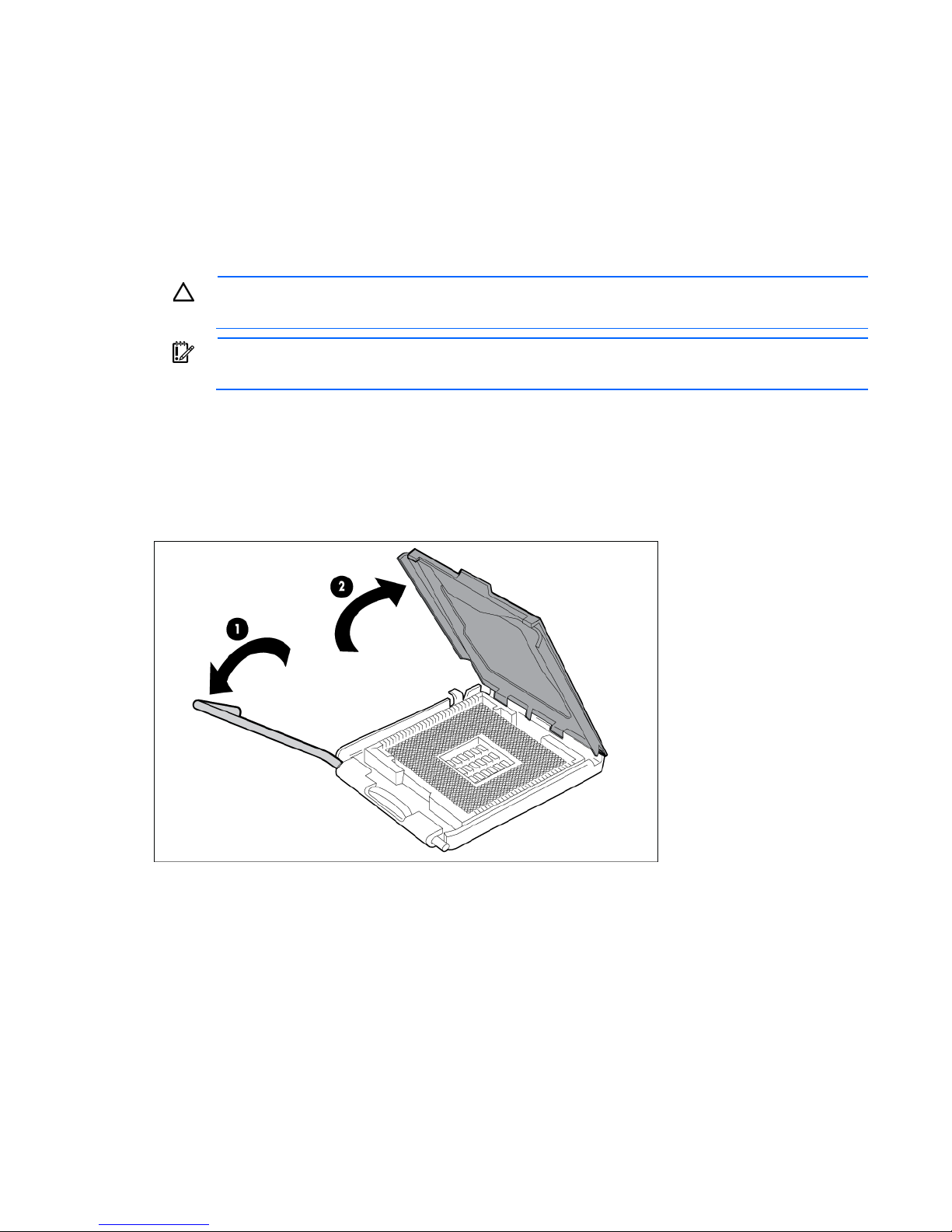
4. Open the processor retaining latch and the processor socket retaining bracket.
Hardware options installation 12
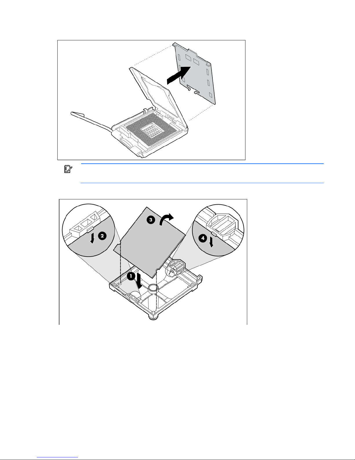
5.
Remove the processor socket protective cover.
IMPORTANT: Be sure the processor remains inside the processor installation tool.
6. If the processor has separated from the installation tool, carefully re-insert the processor in the tool.
Hardware options installation 13
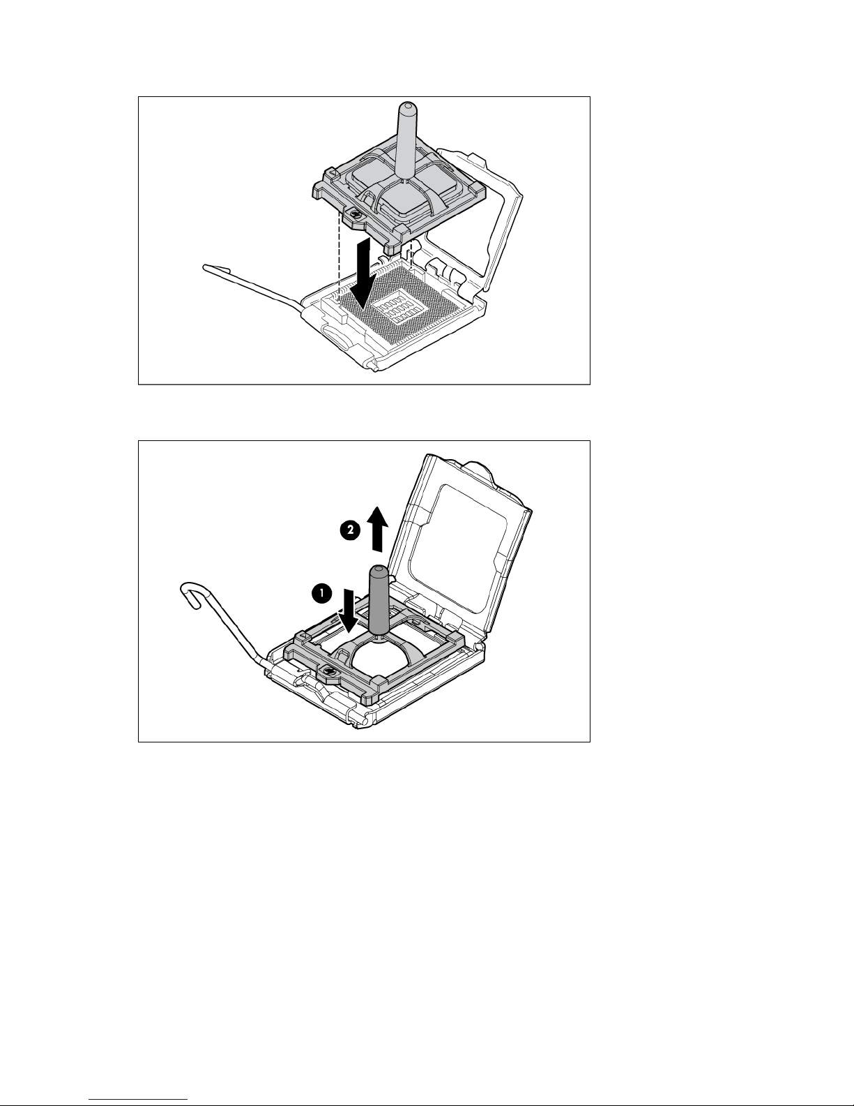
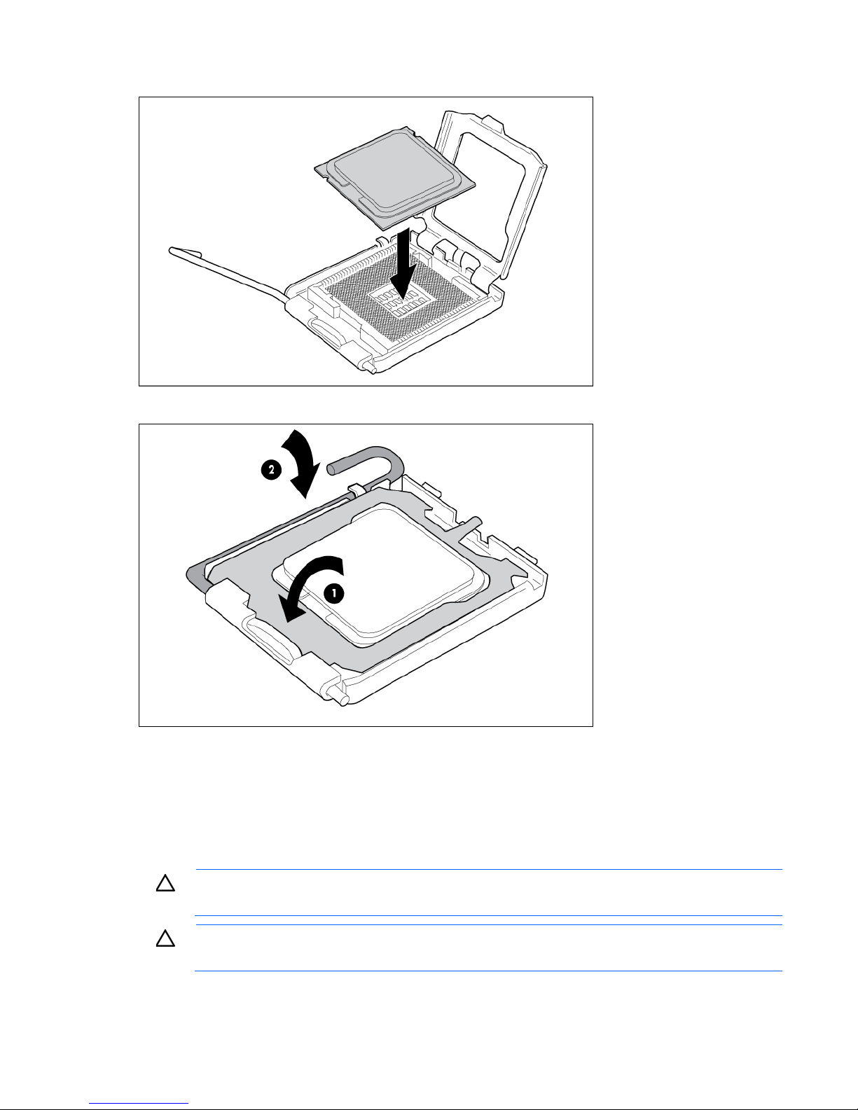
7.
Align the processor installation tool with the socket and install the processor.
8. Press down firmly until the processor installation tool clicks and separates from the processor, and then
remove the processor installation tool.
Hardware options installation 14
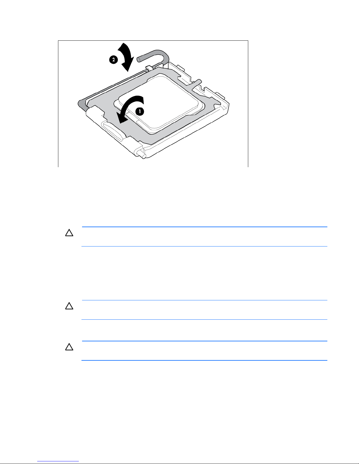
9.
Close the processor socket retaining bracket and the processor retaining latch.
10. Install the heatsink. See the server installation sheet.
11. Install the access panel.
Installing a processor in HP ProLiant ML110 (G2, G3, and G4)
and ProLiant ML150 Generation 2 Servers
CAUTION: To prevent possible server malfunction and damage to the equipment, do not mix
1. Power down the server (on page 6).
2. Extend the server from the rack, if applicable.
3. Remove the access panel ("Access panel" on page 11).
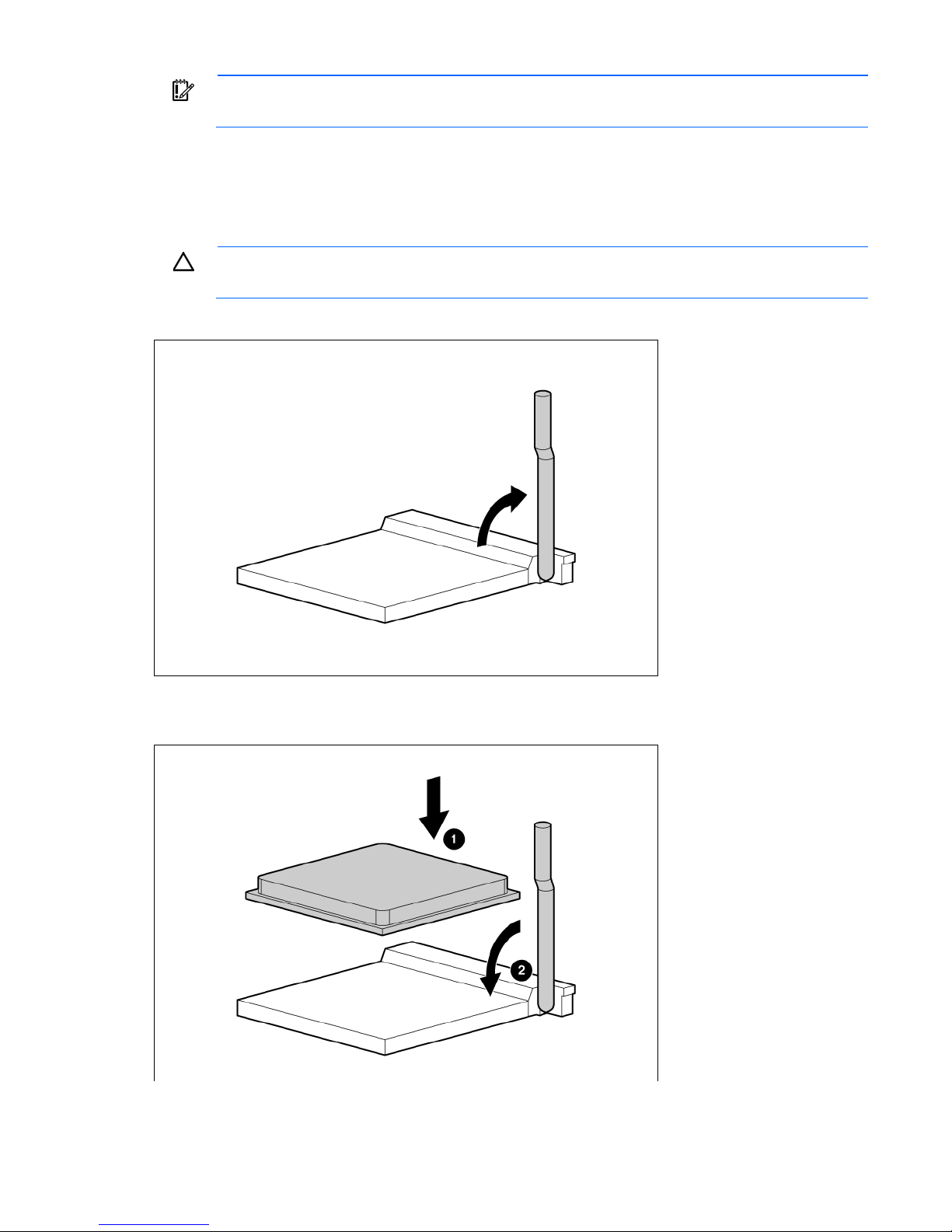
4. Open the processor retaining bracket.
5. Release the processor locking lever.
6. Install the processor and close the processor retaining bracket. Refer to the installation sheet for
single- and dual-core processors or processors with different speeds or cache sizes.
CAUTION: Failure to completely open the processor locking lever prevents the processor from
seating during installation, leading to hardware damage.
server-specific installation instructions.
CAUTION: To prevent possible server malfunction or damage to the equipment, be sure to
completely close the processor locking lever.
Hardware options installation 15
7. Install the heatsink. Refer to the installation sheet for server-specific installation instructions.
8. Install the PPM (if applicable). Refer to the server hood labels or user documentation for specific
information on how to install a PPM.
9. Install the access panel.
Installing a processor in HP ProLiant ML110 Generation 5 Servers
The server uses an embedded PPM as a DC-to-DC converter to provide the proper power to the processor.
To install the component:
1. Power down the server (on page 6).
2. Extend the server from the rack.
3. Remove the access panel ("Access panel" on page 11).
Hardware options installation 16
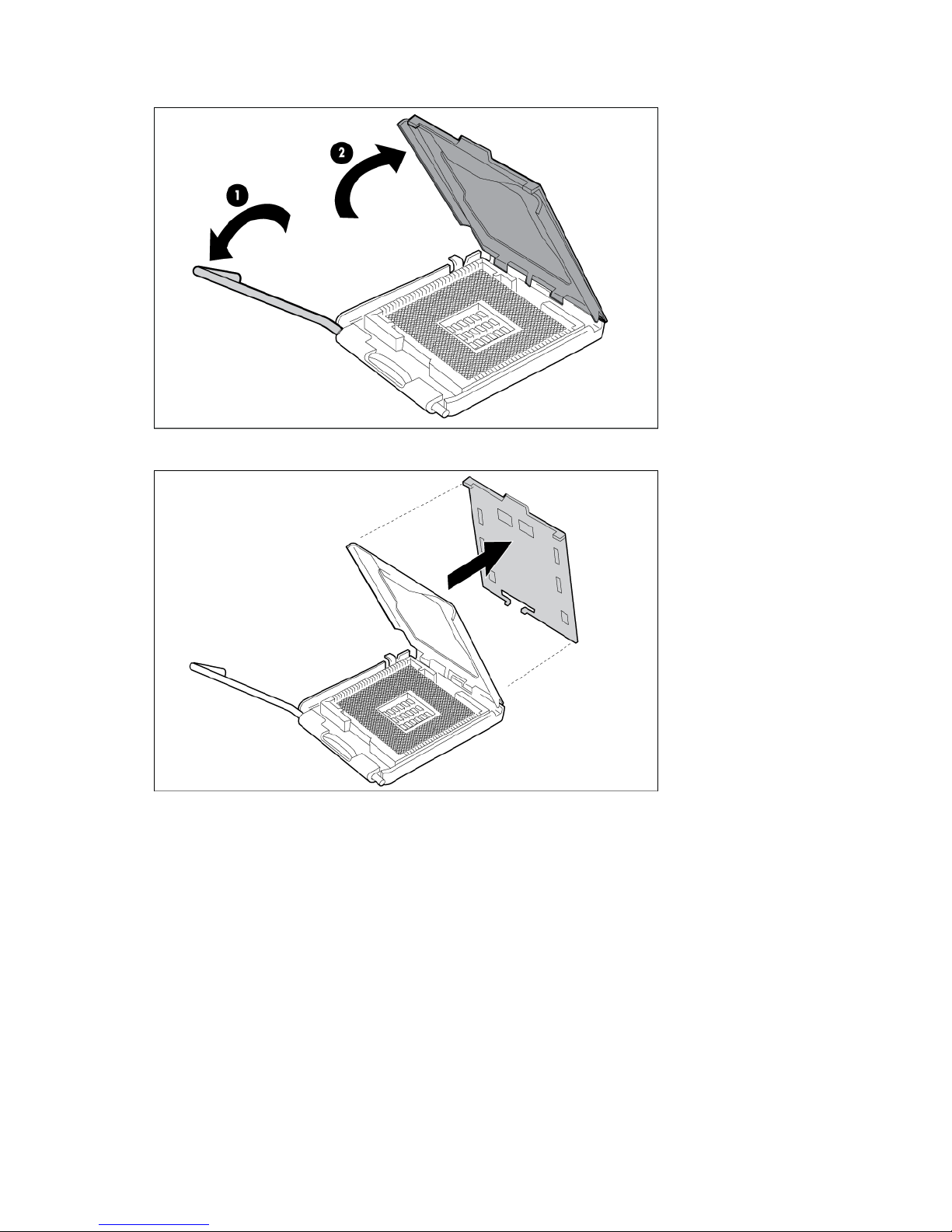
4.
Open the processor retaining latch and the processor socket retaining bracket.
5. Remove the processor socket protective cover.
Hardware options installation 17
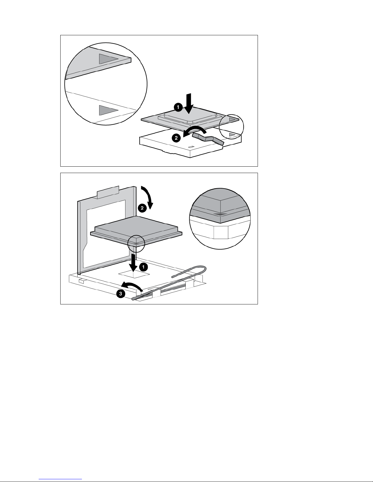
6.
Install the processor.
7. Close the processor socket retaining bracket and the processor retaining latch.
8. Install the heatsink. See the server installation sheet.
9. Install the access panel.
Installing a processor in HP ProLiant ML115 and ML115
Generation 5 Servers
CAUTION: To avoid damage to the processor and system board, only authorized personnel
should attempt to replace or install the processor in this server.
CAUTION: To help avoid damage to the processor and system board, do not install the
processor without using the processor installation tool.
Hardware options installation 18
IMPORTANT: If installing a processor with a faster speed, update the system ROM before
installing the processor.
To install the component:
1. Power down the server (on page 6).
2. Remove the access panel ("Access panel" on page 11).
3. Remove the heatsink fan and the heatsink. For more information, see the server installation sheet.
CAUTION: Failure to completely open the processor locking lever prevents the processor from
seating during installation, leading to hardware damage.
4. Open the processor locking lever.
5. Install the processor.
6. Close the processor locking lever.
Hardware options installation 19
CAUTION: To prevent possible server malfunction or damage to the equipment, be sure to
Embedded
Optional HBA
4
completely close the processor locking lever.
7. Install the heatsink and the heatsink fan. For more information, see the server installation sheet.
8. Install the access panel.
SAS or SATA hard drive options
Some HP ProLiant 100 Series servers support SAS and SATA drives depending on the controller
configuration.
ProLiant server SATA support SAS support Maximum drives
ProLiant ML110 G4 and G5 Servers
ProLiant ML115 and ML115 G5
Servers
ProLiant ML150 G3 Server
ProLiant ML150 G5 Server
For optimal performance, avoid mixing SAS and SATA hard drives.
CAUTION: To prevent improper cooling and thermal damage, do not operate the server unless
all bays are populated with either a component or a blank.
IMPORTANT: If only one hard drive is installed, install it in the bay with the lowest device
number. For device numbering and drive installation guidelines, refer to "SAS and SATA hard
drive guidelines (on page 59)."
IMPORTANT: Some ProLiant 100 Series servers support hot-plug functionality when an optional
SAS or SATA Smart Array controller is installed. For more information, see the installation sheet
that ships with the server.
To install the component:
Embedded Optional HBA 4
Embedded Optional HBA 6
Embedded Optional HBA 8
1. Power down the server (on page 6).
2. Open the bezel, if applicable.
Hardware options installation 20
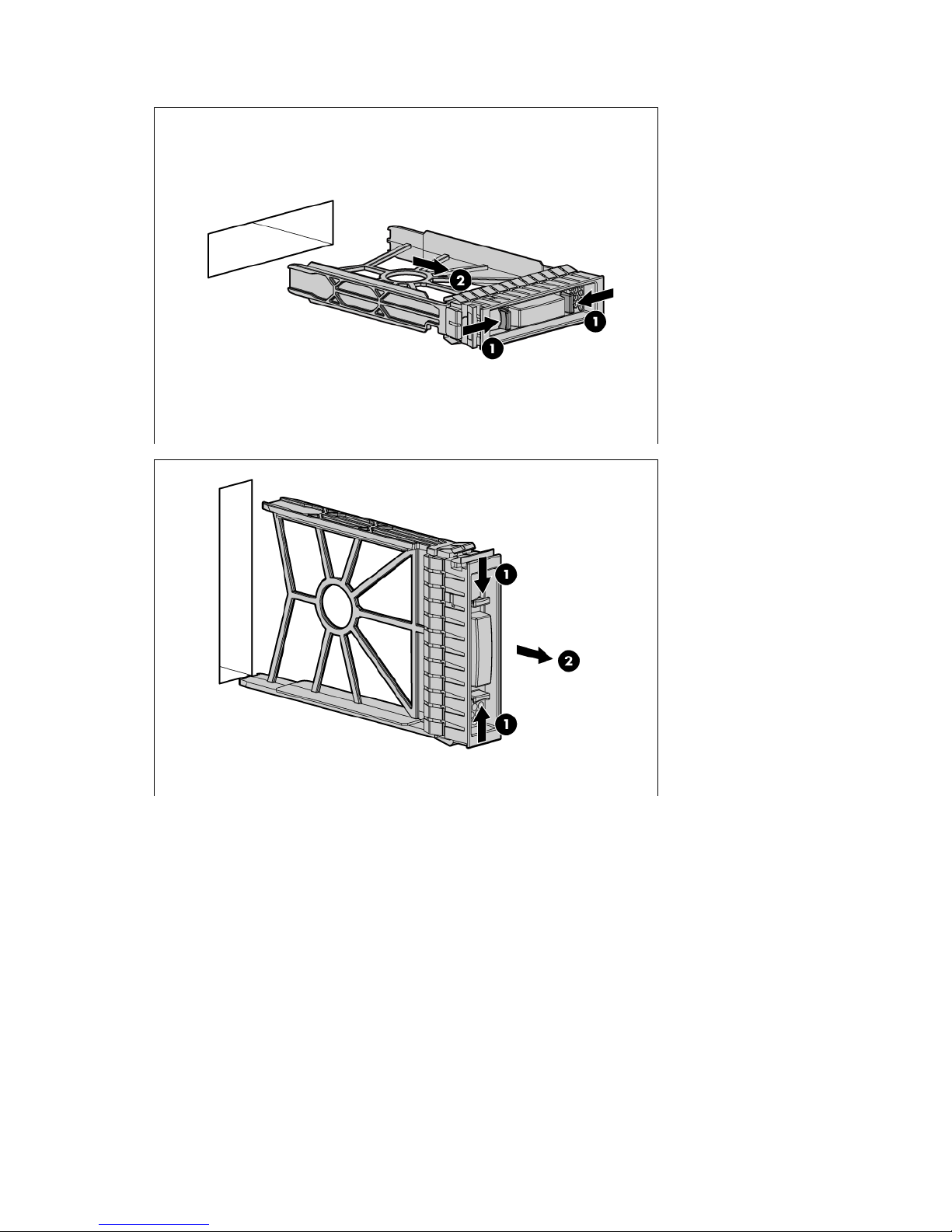
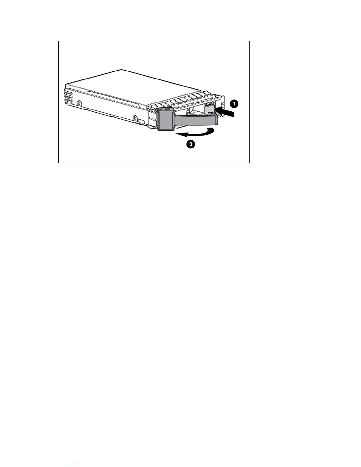
3.
Remove the hard drive blank.
Hardware options installation 21
4.
Prepare the hard drive.
Hardware options installation 22
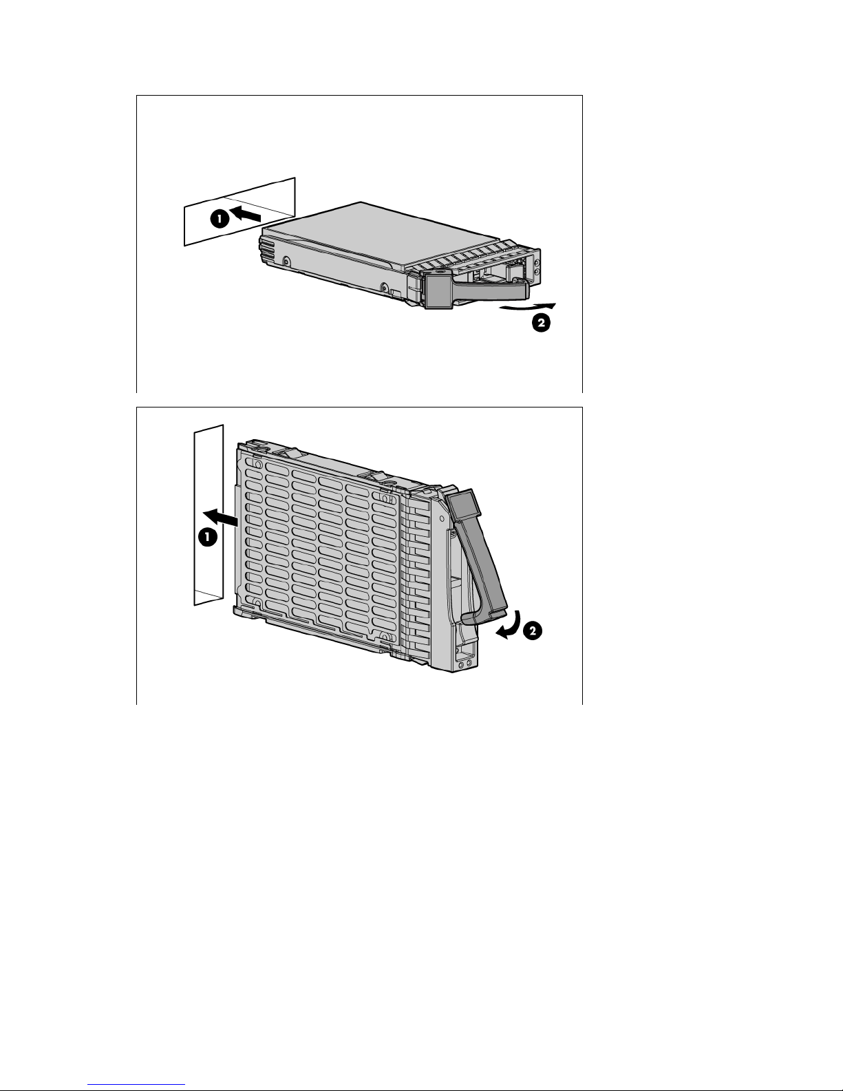
5.
Install the hard drive.
6. Close the bezel.
7. Resume normal server operations.
8. Determine the status of the drive from the hot-plug SAS hard drive LED combinations ("SAS and SATA
hard drive LED combinations" on page 60).
Hard drive LED cable option
This section provides the following procedures:
• Installing the LED cable (ML110 G4) (on page 24)
• Installing the LED cable (ML150 G3) (on page 27)
• Installing the LED cable (ML110 G5, ML115 G5, and ML150 G5) (on page 29)
Hardware options installation 23
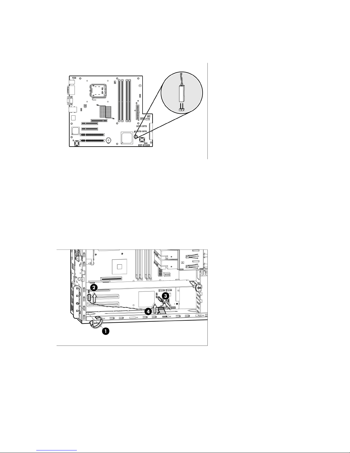
Installing the LED cable (ML110 G4)
Connector location (ML110 G4)
Cabling an HP Smart Array E200 controller card (ML110 G4)
1. Power down the server (on page 6).
2. Remove the access panel ("Access panel" on page 11).
3. Install an HP Smart Array E200 controller card.
For more information, see the documentation that ships with the option and see "Expansion board
options (on page 42)."
4. Connect the LED cable to the controller card and to the system board.
5. Open the cable clamp.
Hardware options installation 24
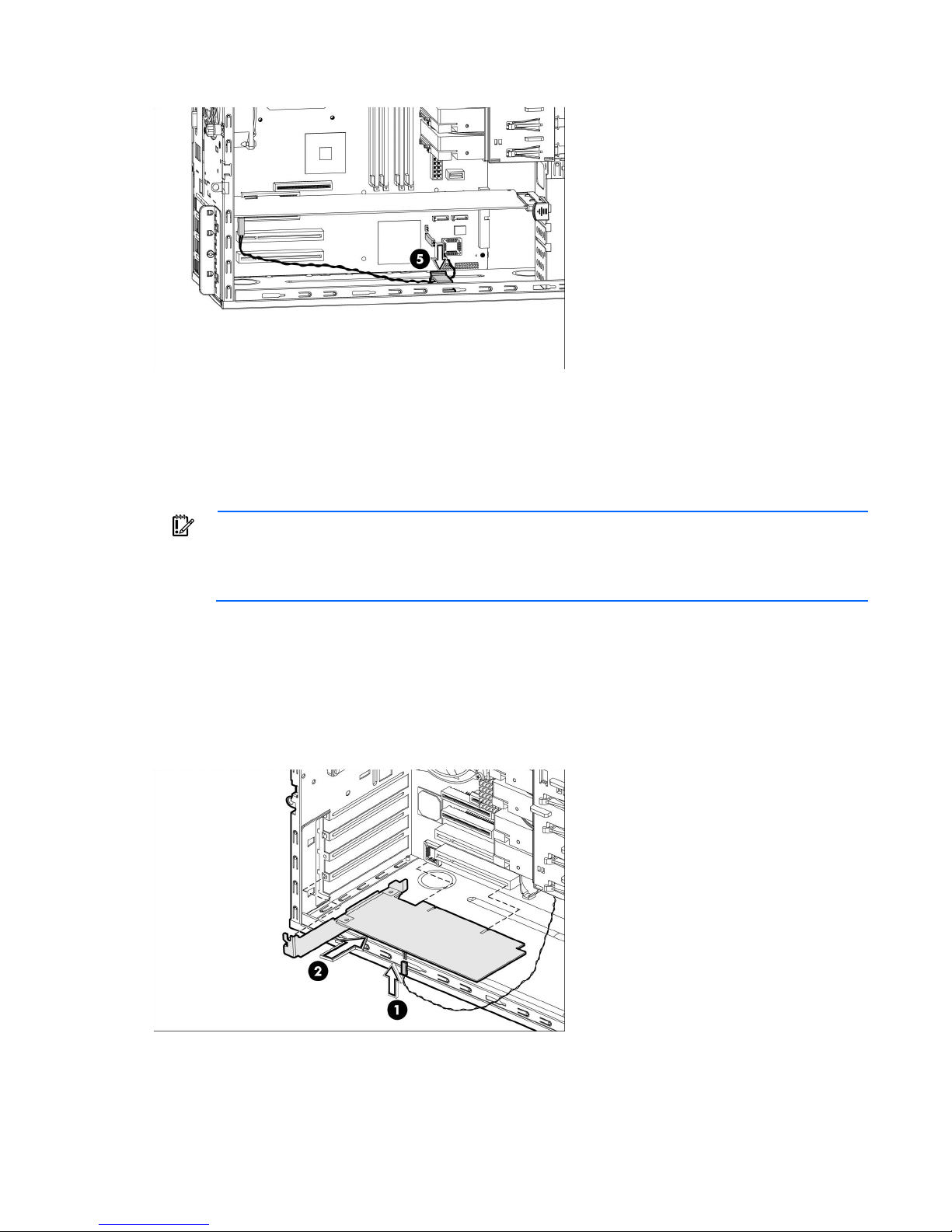
6.
Secure the cable with the cable clamp.
7. Install the access panel.
8. Power up the server (on page 6).
Cabling an HP 8 Internal Port SAS/SATA Host Bus Adapter with RAID card (ML110
G4)
IMPORTANT: The LED cable must be connected to the HP 8 Internal Port SAS/SATA Host Bus
Adapter card before the card is installed in the server. If the card is already installed, remove it
before connecting the cable. For more information, see the HP ProLiant ML110 Generation 4
1. Power down the server (on page 6).
2. Remove the access panel ("Access panel" on page 11).
3. Connect the LED cable to the card.
4. Install the card.
Server Maintenance and Service Guide.
For more information, see the documentation that ships with the option and see "Expansion board
options (on page 42)."
5. Connect the LED cable to the system board.
Hardware options installation 25
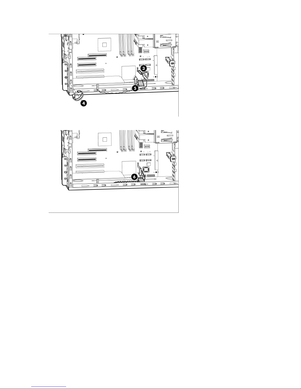
6.
Open the cable clamp.
7. Secure the cable with the cable clamp.
8. Install the access panel.
9. Power up the server (on page 6).
Hardware options installation 26
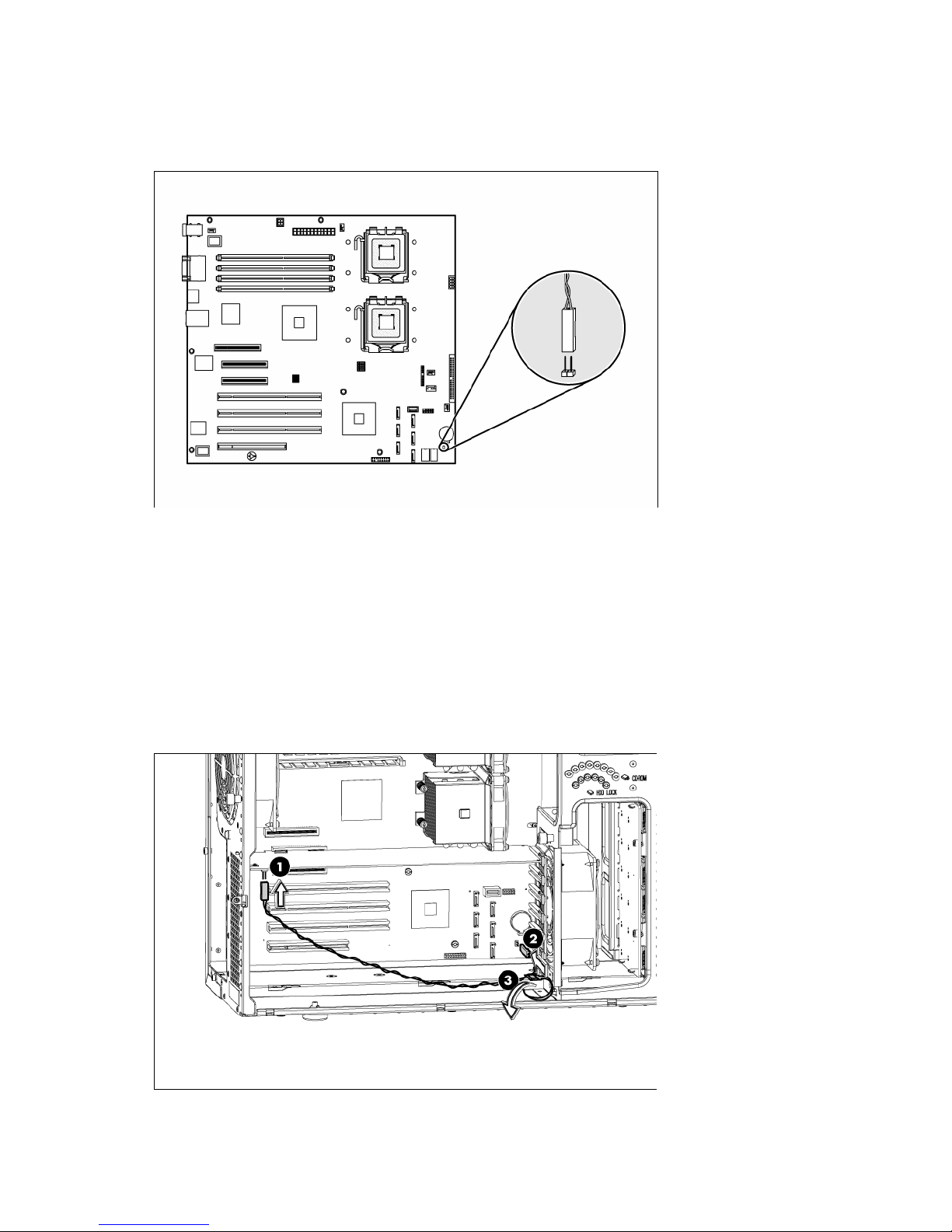
Installing the LED cable (ML150 G3)
Connector location (ML150 G3)
Cabling an HP Smart Array E200 controller card (ML150 G3)
1. Power down the server (on page 6).
2. Remove the access panel ("Access panel" on page 11).
3. Install the card.
For more information, see the documentation that ships with the option and see "Expansion board
options (on page 42)."
4. Connect the LED cable to the card and to the system board.
5. Unfasten the cable tie.
Hardware options installation 27
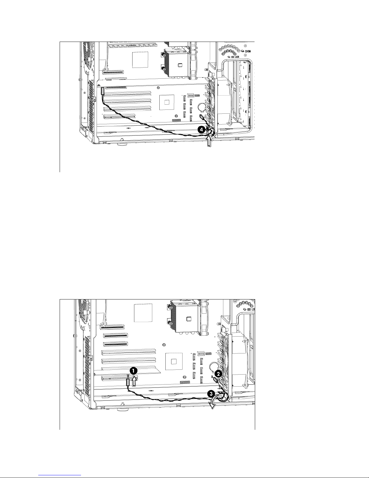
6.
Secure the cable with the cable tie.
7. Install the access panel.
8. Power up the server (on page 6).
Cabling an HP 8 Internal Port SAS/SATA Host Bus Adapter with RAID card (ML150
G3)
1. Power down the server (on page 6).
2. Remove the access panel ("Access panel" on page 11).
3. Install the card.
For more information, see the documentation that ships with the option and see "Expansion board
options (on page 42)."
4. Connect the LED cable to the card and to the system board.
5. Unfasten the cable tie.
Hardware options installation 28

6.
Secure the cable with the cable tie.
7. Install the access panel.
8. Power up the server (on page 6).
Installing the LED cable (ML110 G5, ML115 G5, and ML150 G5)
Connector locations (ML110 G5, ML115 G5, and ML150 G5)
• HP ProLiant ML110 Generation 5 Server
Hardware options installation 29
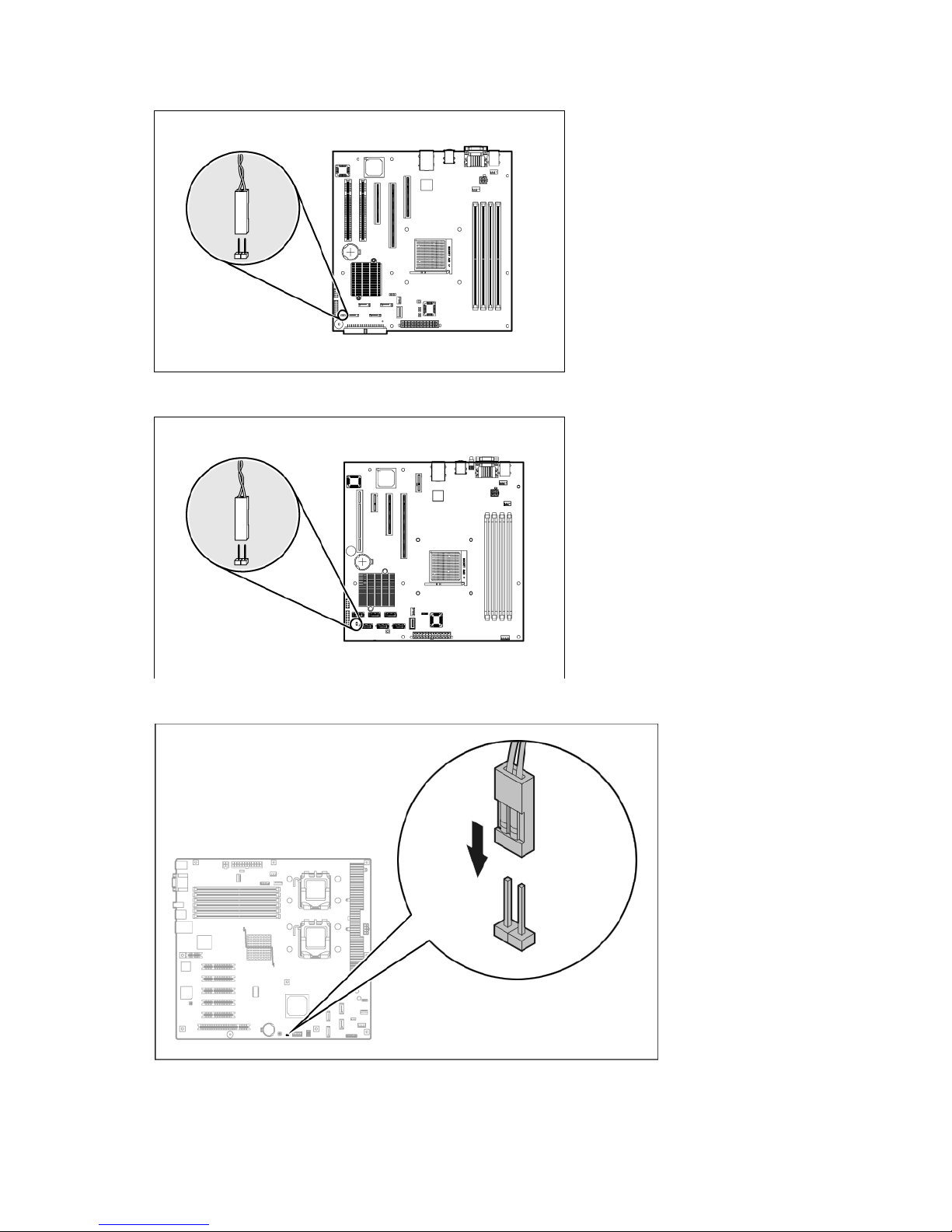
• HP ProLiant ML115 Server
• HP ProLiant ML115 Generation 5 Server
• HP ProLiant ML150 Generation 5 Server
Hardware options installation 30
 Loading...