

HP ProLiant m710x User And Maintenance Manual

HPE ProLiant m710x Server Cartridge User and Maintenance Guide
Abstract
This document is for the person who installs, administers, services, and troubleshoots
cartridges. This guide describes identification and maintenance procedures, and
specifications and requirements for hardware components and software. Hewlett Packard
Enterprise assumes you are qualified in the servicing of computer equipment, trained in
recognizing hazards in products, and are familiar with weight and stability precautions.
Part Number: 864397-002a
Published: August 2017
Edition: 3

©
Copyright 2016, 2017 Hewlett Packard Enterprise Development LP
Notices
The information contained herein is subject to change without notice. The only warranties for Hewlett
Packard Enterprise products and services are set forth in the express warranty statements accompanying
such products and services. Nothing herein should be construed as constituting an additional warranty.
Hewlett Packard Enterprise shall not be liable for technical or editorial errors or omissions contained
herein.
Confidential computer software. Valid license from Hewlett Packard Enterprise required for possession,
use, or copying. Consistent with FAR 12.211 and 12.212, Commercial Computer Software, Computer
Software Documentation, and Technical Data for Commercial Items are licensed to the U.S. Government
under vendor's standard commercial license.
Links to third-party websites take you outside the Hewlett Packard Enterprise website. Hewlett Packard
Enterprise has no control over and is not responsible for information outside the Hewlett Packard
Enterprise website.
Acknowledgments
Linux® is the registered trademark of Linus Torvalds in the U.S. and other countries.
Intel®, Itanium®, Pentium®, Intel Inside®, and the Intel Inside logo are trademarks of Intel Corporation in
the United States and other countries.

Contents
Component identification.......................................................................6
Operations............................................................................................. 10
Cartridge LEDs and buttons..........................................................................................................6
Cartridge components...................................................................................................................7
DIMM slot numbering......................................................................................................... 7
M.2 SSD slot numbering.................................................................................................... 8
Cartridge slot and switch module bay identification...................................................................... 8
Power down the cartridge........................................................................................................... 10
Power down a cartridge remotely.....................................................................................10
Power down a cartridge locally........................................................................................ 10
Extend the chassis from the rack................................................................................................ 11
Remove the access panel...........................................................................................................12
Remove the cartridge blank........................................................................................................ 13
Remove the cartridge..................................................................................................................14
Install the cartridge......................................................................................................................14
Install the cartridge blank............................................................................................................ 15
Install the access panel...............................................................................................................16
Power up the cartridge................................................................................................................16
Power up a cartridge remotely......................................................................................... 16
Power up a cartridge locally............................................................................................. 17
Log in to the iLO CM firmware.................................................................................................... 17
Setup...................................................................................................... 18
Overview..................................................................................................................................... 18
Installing and configuring the HPE Moonshot 1500 Chassis...................................................... 18
Installing and configuring the switch and uplink modules........................................................... 18
Installing the cartridge.................................................................................................................18
Powering up the chassis............................................................................................................. 19
Powering up the node................................................................................................................. 19
Updating cartridge firmware........................................................................................................19
Installing the operating system................................................................................................... 20
Registering the product...............................................................................................................20
HPE Trusted Platform Module.................................................................................................... 20
Retaining the recovery key/password.............................................................................. 20
Enabling the Trusted Platform Module.............................................................................21
Configuration.........................................................................................22
Enabling video on monitor.......................................................................................................... 22
Enabling video on monitor for Windows 2012, Windows 8, Windows 8.1, Windows
10, RHEL 7.3, and CentOS 7.3........................................................................................22
Enabling video on monitor for Windows 7 .......................................................................23
Enabling video on monitor for Linux (except RHEL 7.3 and CentOS 7.3)....................... 24
Hardware options installation..............................................................26
Contents 3

Hewlett Packard Enterprise product QuickSpecs....................................................................... 26
Installing a DIMM........................................................................................................................ 26
Installing an M.2 solid state device............................................................................................. 26
Install a 42 mm M.2 solid state device............................................................................. 27
Install an 80 mm M.2 solid state device........................................................................... 27
Install a 110 mm M.2 solid state device............................................................................28
Software and configuration utilities....................................................30
Product QuickSpecs................................................................................................................... 30
Supported operating systems and drivers matrix .......................................................................30
HPE Moonshot iLO Chassis Management Firmware................................................................. 30
HPE Moonshot iLO CM Integrated Management Log......................................................30
HPE Moonshot iLO CM Event Log...................................................................................30
HPE Insight Cluster Management Utility.....................................................................................31
HPE Moonshot Component Pack............................................................................................... 31
Smart Update Manager....................................................................................................31
UEFI System Utilities.................................................................................................................. 31
Using UEFI System Utilities............................................................................................. 31
Restore default system settings....................................................................................... 32
Embedded UEFI shell...................................................................................................... 32
Powering on and selecting boot options.......................................................................... 32
Troubleshooting....................................................................................33
Troubleshooting resources..........................................................................................................33
Illustrated parts catalog........................................................................34
Customer self repair....................................................................................................................34
Cartridge replaceable components............................................................................................. 42
Server cartridge spare parts.............................................................................................43
DIMM spare parts.............................................................................................................43
Solid state device spare parts.......................................................................................... 43
HPE ProLiant m710x to EL1000 cable Kit spare parts.................................................... 43
Removal and replacement procedures...............................................44
Preparation procedures.............................................................................................................. 44
Safety considerations..................................................................................................................44
Preventing electrostatic discharge................................................................................... 44
Symbols on equipment.....................................................................................................44
Warnings and cautions.....................................................................................................45
Removing and replacing a cartridge........................................................................................... 45
Removing and replacing a cartridge blank..................................................................................47
Removing and replacing a DIMM................................................................................................48
Removing and replacing a solid state device..............................................................................48
Warranty and regulatory information..................................................50
Warranty information...................................................................................................................50
Regulatory information................................................................................................................50
Turkey RoHS material content declaration.......................................................................50
Ukraine RoHS material content declaration..................................................................... 51
4 Contents

Electrostatic discharge.........................................................................52
Preventing electrostatic discharge.............................................................................................. 52
Grounding methods to prevent electrostatic discharge...............................................................52
Specifications........................................................................................53
Chassis environmental specifications......................................................................................... 53
Chassis specifications ................................................................................................................53
Cartridge specifications...............................................................................................................53
Websites................................................................................................ 54
Support and other resources...............................................................55
Accessing Hewlett Packard Enterprise Support......................................................................... 55
Accessing updates......................................................................................................................55
Customer self repair....................................................................................................................56
Remote support.......................................................................................................................... 56
Acronyms and abbreviations...............................................................57
Documentation feedback..................................................................... 58
Contents 5
Component identification
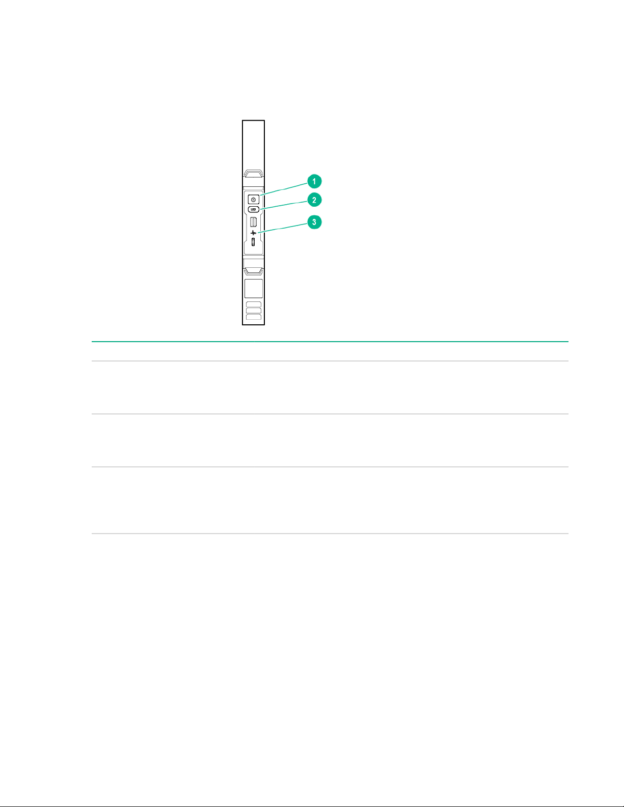
Cartridge LEDs and buttons
Item Description Status
1 Cartridge power LED/
button
2 Cartridge UID LED/button
3 Cartridge health LED
• Green = Normal operation
• Amber = Standby operation
• Off = No power
• Blue = Cartridge ID is selected.
• Flashing blue = Cartridge firmware update is in progress.
• Off = Cartridge ID is not selected.
• Green = Normal operation
• Flashing amber = Degraded condition
• Flashing red = Critical condition
• Off = No power
6 Component identification
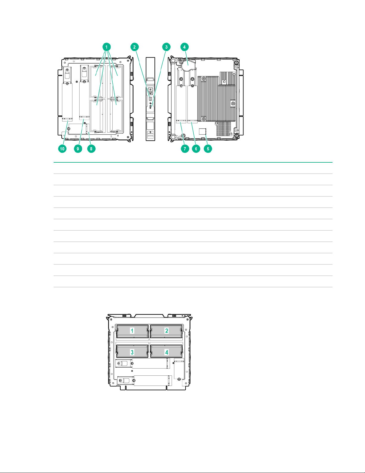
Cartridge components
Item Description
1 DIMM slots (4)
2 Mini display port
3 Micro USB port
4 Battery
5 USB port
6 Solid state device connector 5 for 80/110 mm M.2 SSDs
7 Solid state device connector 4 for 80/110 mm M.2 SSDs
8 Solid state device connector 3 for 42 mm M.2 SSDs
9 Solid state device connector 2 for 80 mm M.2 SSDs
10 Solid state device connector 1 for 80 mm M.2 SSDs
DIMM slot numbering
Cartridge components 7
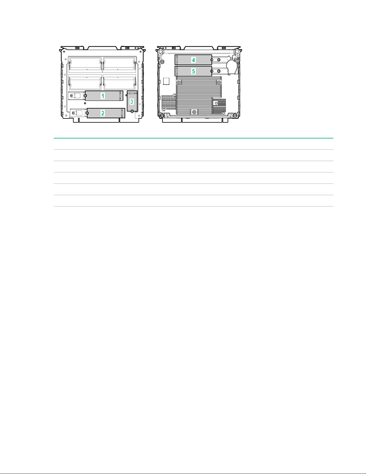
M.2 SSD slot numbering
Item Description BIOS numbering
1 Solid state device slot 1 PCIe Slot 3
2 Solid state device slot 2 PCIe Slot 2
3 Solid state device slot 3 PCIe/SATA Slot 1
4 Solid state device slot 4 PCIe Slot 4
5 Solid state device slot 5 PCIe Slot 5
To identify the m.2 slots, view System Information -> PCIe information.
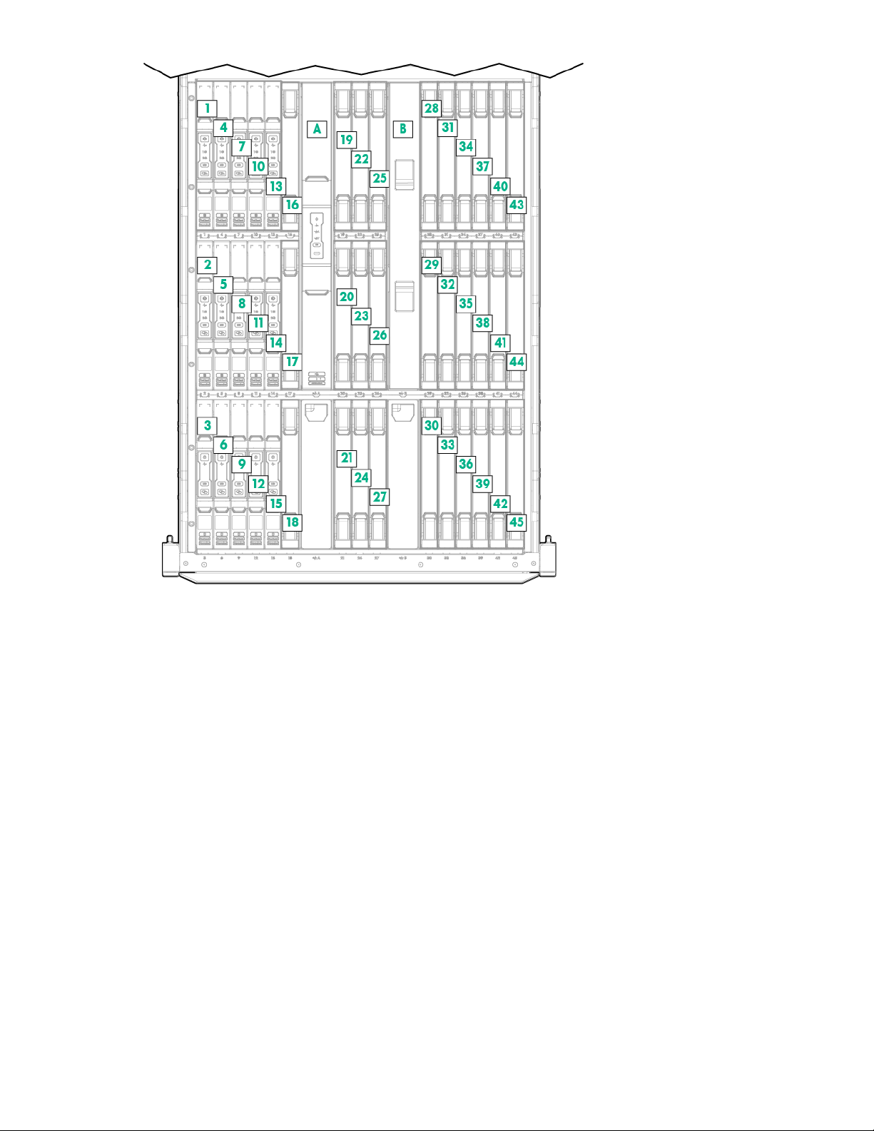
Cartridge slot and switch module bay identification
The chassis provides 45 cartridge slots (1-45) and two switch module bays (A-B).
8 M.2 SSD slot numbering
Component identification 9

Operations
Power down the cartridge
Review the following information before powering down the cartridge:
• Before powering down a cartridge for any upgrade or maintenance procedures, always perform a
backup of critical cartridge data and programs.
• Depending on the cartridge model, the cartridge may be a single-node or a multi-node cartridge.
Always power down all nodes on the cartridge before removing it from the chassis.
• If you are powering down one node but leaving other nodes in a powered up state on the cartridge, the
cartridge power LED will remain illuminated, indicating at least one node is powered up.
Cartridges can be powered down individually and as a group of all cartridges in the chassis. Choose the
procedure in this section that fits your need.
When entering cartridge commands provided in this section, you can use one command to address
multiple cartridges. Use commas to separate non-contiguous numbers (omit spaces), or a dash to denote
a range (for example, C1,3-9N1-4). For more information about using commands, see the HPE Moonshot
iLO Chassis Management CLI User Guide in the Hewlett Packard Enterprise Information Library (
www.hpe.com/info/moonshot/docs).
Power down a cartridge remotely
http://
Procedure
1. Log in to the iLO CM firmware on page 17.
2. Power down the cartridge by issuing the appropriate command:
• For a cartridge running a functioning OS:
◦ Single node:
set node power off shutdown C<x>N<y>
◦ Multiple nodes (4):
set node power off shutdown C<x>N1-4
• For a nonresponsive system or when an OS has not been installed:
◦ Multiple nodes (4):
set node power off force C<x>N1-4
• For all cartridges:
set node power off force all
3. Verify that the power is off by issuing the following command:
show node power {CxNy}
Power down a cartridge locally
Procedure
1. Log in to the iLO CM firmware on page 17.
2. Power down the cartridge according to the current cartridge state:
• If the cartridge power LED is green, press and release the cartridge power button.
10 Operations
This method initiates a controlled shutdown of applications and the OS on any active nodes before
the cartridge enters standby mode.
• If the cartridge is unresponsive, press and hold the cartridge power button for 4 seconds to initiate
a forced shutdown of any active nodes.
• If the cartridge power LED is amber, the cartridge is in standby mode and no nodes are active. No
further action is required.
set node power off force all
3. Verify that the power is off by reviewing the status of the cartridge power LED.
For more information, see Cartridge LEDs and buttons on page 6."
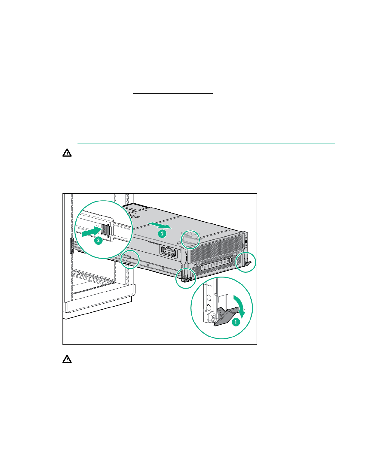
Extend the chassis from the rack
Procedure
1. Pull down the quick release levers on each side of the chassis.
WARNING:
To reduce the risk of personal injury or equipment damage, be sure that the rack is adequately
stabilized before extending a component from the rack.
2. Extend the chassis from the rack until it locks once.
3. Press the push tab on the rail, and then fully extend the chassis.
WARNING:
To reduce the risk of personal injury, be careful when pressing the server rail-release latches and
sliding the server into the rack. The sliding rails could pinch your fingers.
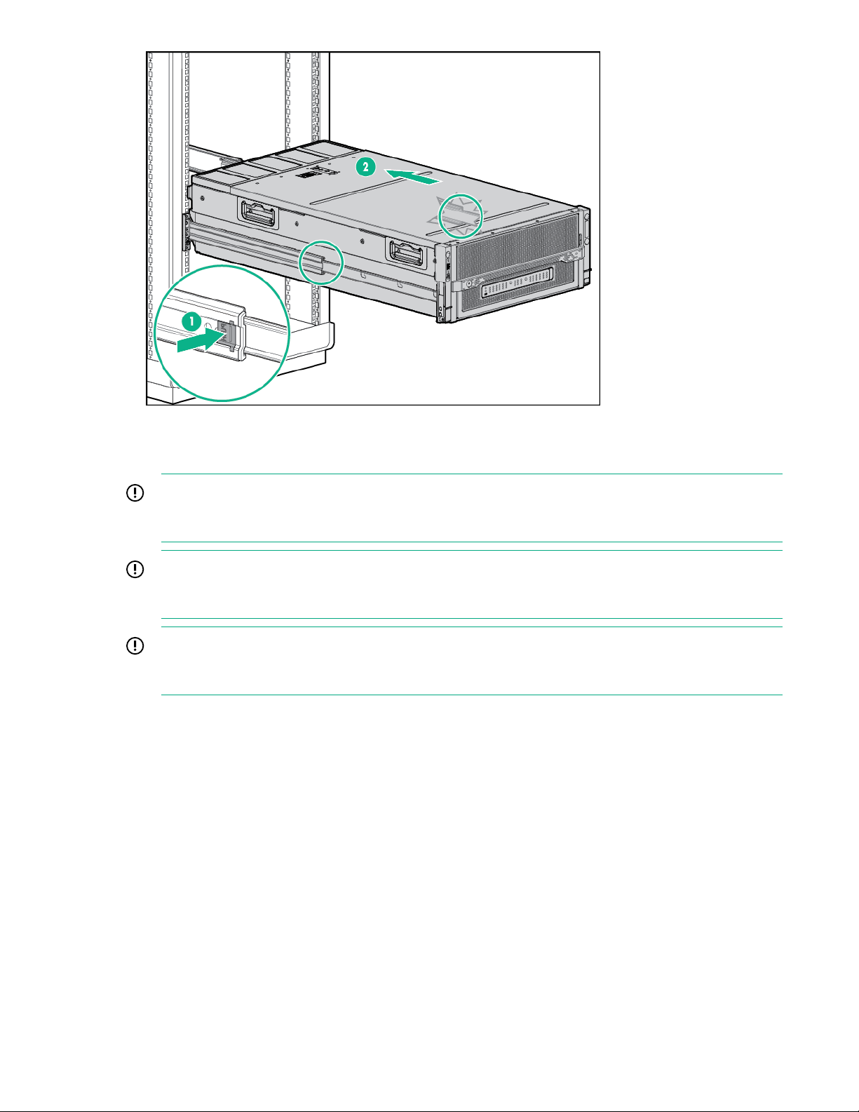
4. After installing or maintaining the system, slide the chassis back into the rack, and then press the
chassis firmly into the rack to secure it in place.
Extend the chassis from the rack 11
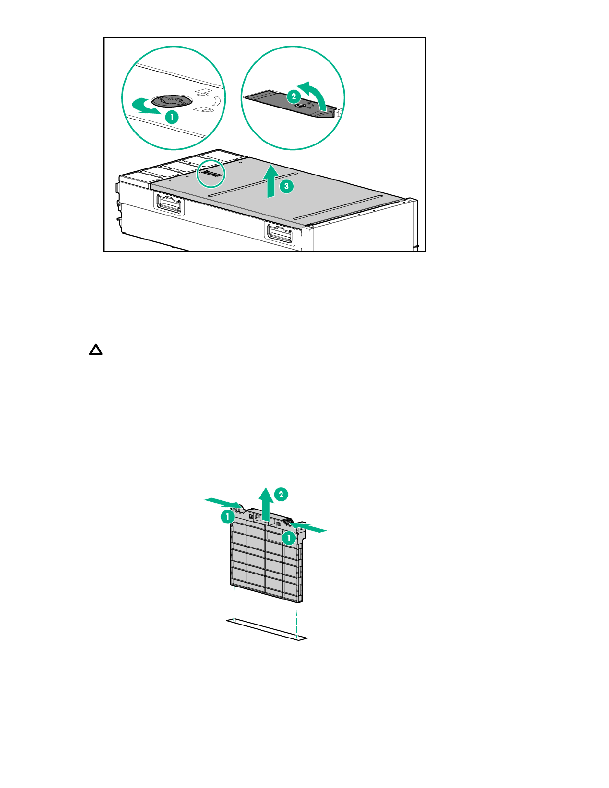
Remove the access panel
IMPORTANT:
After performing a procedure inside the chassis, always install the access panel on the chassis
when complete. Do not operate the chassis for long periods of time with the access panel removed.
IMPORTANT:
To maintain appropriate cooling, fans will operate at a high speed when the access panel is
removed.
IMPORTANT:
When the access panel is removed, the cartridge might be placed into a low power operating state
to reduce thermal stress.
Procedure
1. If the locking latch is locked, use a T-15 Torx screwdriver to unlock the latch.
2. Open the locking latch.
The access panel slides back, releasing it from the chassis.
3. Lift and remove the access panel.
12 Remove the access panel
Turn the access panel over to locate the HPE Moonshot 1500 Chassis label. This label provides
information on LED status indicators, component identification, and cartridge and switch installation
procedures.
Remove the cartridge blank
CAUTION:
For proper cooling, be sure that a cartridge or a cartridge blank is always installed in each cartridge
slot in the chassis. When replacing a cartridge, leave the cartridge slot empty for no more than 30
seconds. Failure to do so can disrupt airflow in the chassis.
Procedure
1. Extend the chassis from the rack on page 11.
2. Remove the access panel on page 12.
3. Remove the cartridge blank from the chassis.
Remove the cartridge blank 13
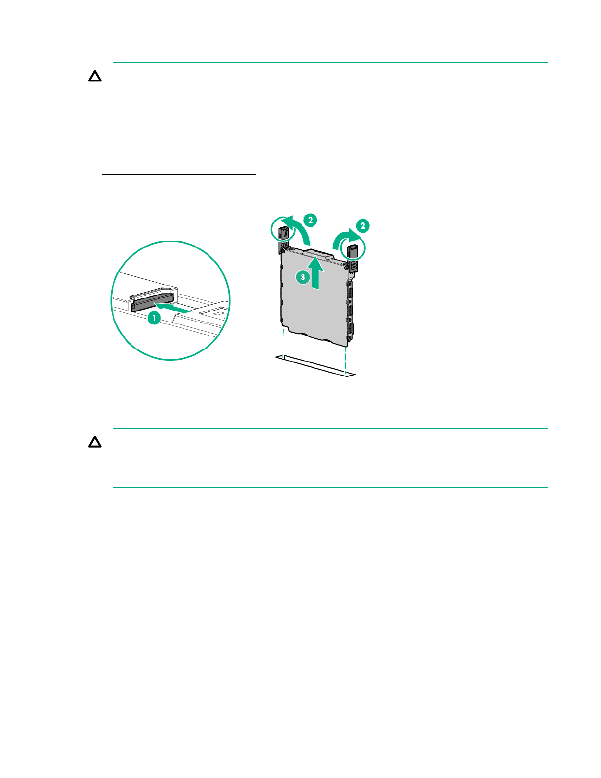
Remove the cartridge
CAUTION:
For proper cooling, be sure that a cartridge or a cartridge blank is always installed in each cartridge
slot in the chassis. When replacing a cartridge, leave the cartridge slot empty for no more than 30
seconds. Failure to do so can disrupt airflow in the chassis.
Procedure
1. Power down the node or cartridge (Power down the cartridge on page 10).
2. Extend the chassis from the rack on page 11.
3. Remove the access panel on page 12.
4. Remove the cartridge.
Install the cartridge
CAUTION:
For proper cooling, be sure that a cartridge or a cartridge blank is always installed in each cartridge
slot in the chassis. When replacing a cartridge, leave the cartridge slot empty for no more than 30
seconds. Failure to do so can disrupt airflow in the chassis.
Procedure
1. Extend the chassis from the rack on page 11.
2. Remove the access panel on page 12.
3. Prepare the cartridge.
14 Remove the cartridge

4. Do one of the following:
• Remove the cartridge on page 14.
• Remove the cartridge blank on page 13.
5. Align and install the cartridge into the chassis.
6. Install the access panel on page 16.
7. Slide the chassis back into the rack (Extend the chassis from the rack on page 11).
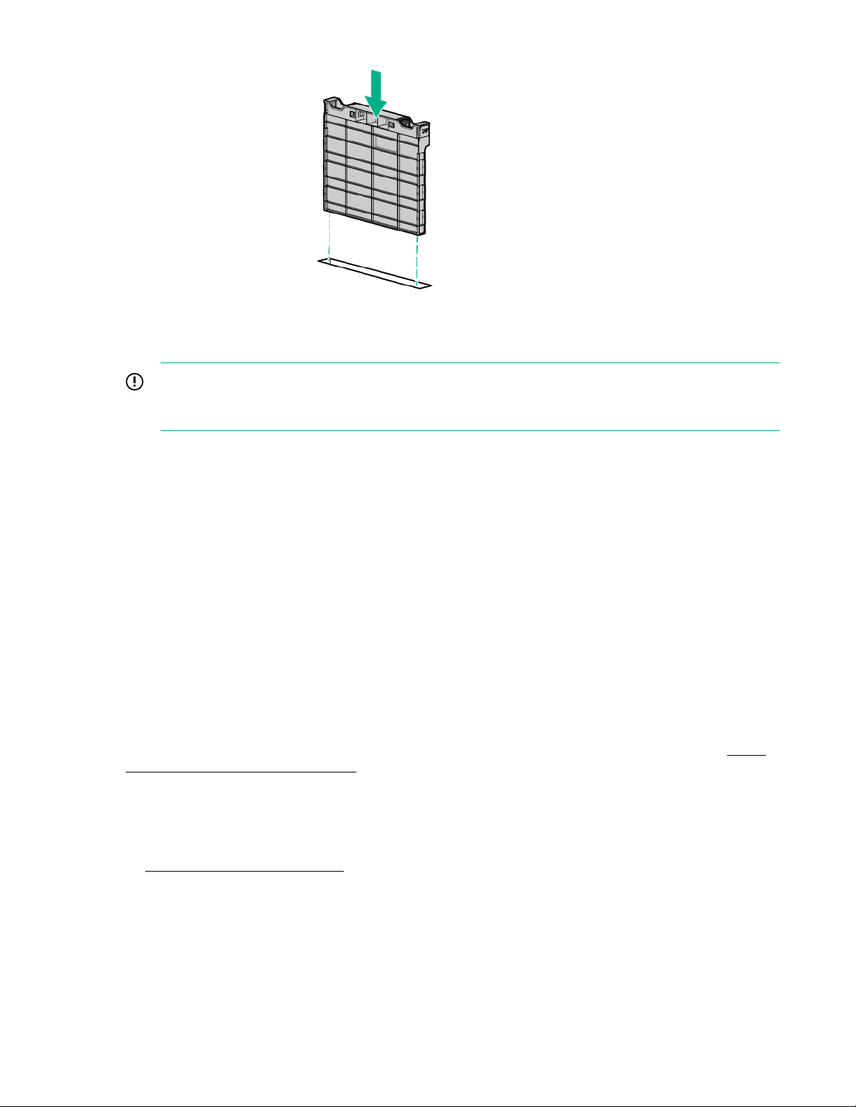
Install the cartridge blank
CAUTION:
For proper cooling, be sure that a cartridge or a cartridge blank is always installed in each cartridge
slot in the chassis. When replacing a cartridge, leave the cartridge slot empty for no more than 30
seconds. Failure to do so can disrupt airflow in the chassis.
Procedure
1. Extend the chassis from the rack on page 11.
2. Remove the access panel on page 12
3. Align and install the cartridge into the chassis.
Install the cartridge blank 15
Install the access panel
IMPORTANT:
After performing a procedure inside the chassis, always install the access panel on the chassis
when complete. Do not operate the chassis for long periods of time with the access panel removed.
Procedure
1. Place the access panel on top of the chassis.
2. Slide the access panel toward the front of the chassis. The access panel locks into position.
Power up the cartridge
Review the following information before powering up the cartridge:
• Depending on the cartridge model, the cartridge may be a single-node or a multi-node cartridge.
• Upon installation into the chassis, auxiliary power is automatically provided to the cartridge. Depending
on the chassis autopower setting, nodes may power up automatically upon cartridge installation.
Cartridges can be powered up individually and as a group of all cartridges in the chassis. Choose the
procedure in this section that fits your need.
When entering cartridge commands provided in this section, you can use one command to address
multiple cartridges. Use commas to separate non-contiguous numbers (omit spaces), or a dash to denote
a range (for example, C1,3-9N1-4). For more information about using commands, see the HPE Moonshot
iLO Chassis Management CLI User Guide in the Hewlett Packard Enterprise Information Library (http://
www.hpe.com/info/moonshot/docs).
Power up a cartridge remotely
Procedure
1. Log in to the iLO CM firmware on page 17.
2. Show the installed cartridges to determine node status:show node power {C<x>N<y>|all}
3. Power up the cartridge by issuing the appropriate command:
16 Install the access panel

• Single node:set node power on C<x>N<y>
• Multiple nodes (4):set node power on C<x>N1-4
• For all cartridges:set node power on all
4. Verify that the power is on by issuing the following command:show node power {CxNy}
Power up a cartridge locally
Procedure
1. Press and release the cartridge power button.
This method powers on all nodes.
2. Verify that the power is on by reviewing the status of the cartridge power LED.
For more information, see Cartridge LEDs and buttons on page 6.
Log in to the iLO CM firmware
Procedure
1. Connect to the iLO CM firmware locally or remotely:
To access the iLO CM firmware through the GUI, you must know the serial number or IP address of
the iLO CM. The serial number can be found on the chassis hood label.
• To connect remotely, use a browser or SSH session over the network.
• To connect locally, use a serial cable to connect a PC or terminal to the iLO CM management serial
port on the Moonshot 1500 CM module.
2. If no changes were made, enter the user name and password assigned for the chassis or the default
user name and password:
Default username:
Administrator
Default password:
password
For more information about the iLO CM firmware, see the HPE Moonshot iLO Chassis Management CLI
User Guide in the Hewlett Packard Enterprise Information Library (
docs).
http://www.hpe.com/info/moonshot/
Power up a cartridge locally 17

Setup
IMPORTANT:
The HPE Synergy Gen10 compute module installation involves a minimum upgrade requirement for
component compatibility purposes. To ensure proper system functionality, you must update your
system to Release Set Version 3.00.20170707 (or later) before installing and operating your
compute module. Go to http://www.hpe.com/downloads/synergy and see the HPE Synergy
Firmware Update Overview guide at http://www.hpe.com/info/synergy-firmware-update-
overview-en for specific details on updating compute module components.
Overview
Installation of a cartridge requires the following steps:
Procedure
1. Install and configure the HPE Moonshot 1500 Chassis (Installing and configuring the HPE
Moonshot 1500 Chassis on page 18).
2. Install and configure the switch and uplink modules (Installing and configuring the switch and
uplink modules on page 18).
3. Install the solid state device (Installing an M.2 solid state device on page 26).
4. Install the cartridge on page 14.
5. Power up the chassis (Powering up the chassis on page 19).
6. Power up the node (Powering up the node on page 19).
7. Update the cartridge firmware (Updating cartridge firmware on page 19).
8. Install the operating system (Installing the operating system on page 20).
9. Register the product (Registering the product on page 20).
Installing and configuring the HPE Moonshot 1500 Chassis
Before performing any cartridge-specific procedures, install the HPE ProLiant Moonshot 1500 Chassis.
For more information on installing a chassis, see the HPE Moonshot 1500 Chassis Setup and Installation
Guide in the Hewlett Packard Enterprise Information Library (
docs).
http://www.hpe.com/info/moonshot/
Installing and configuring the switch and uplink modules
For specific steps to install the switch modules and uplink modules, see the switch documentation in the
Hewlett Packard Enterprise Information Library (http://www.hpe.com/info/moonshot/docs).
Installing the cartridge
Procedure
1. Do one of the following:
• Remove the cartridge blank on page 13.
• Remove the cartridge on page 14.
2. Install the cartridge on page 14.
18 Setup
 Loading...