

HP ProLiant EC200a User Manual

HPE ProLiant EC200a Managed
Abstract
This document is for the person who installs, administers, and troubleshoots servers and storage systems. Hewlett Packard Enterprise
Part Number: 856709-002
September 2016
Edition: 2
Hybrid Server
User Guide
assumes that you are qualified in the servicing of computer equipment and trained in recognizing hazards in products with hazardous
energy levels.

© Copyright 2016 Hewlett Packard Enterprise Development LP
The information contained herein is subject to change without notice. The only warranties for Hewlett Packard Enterprise products and services
are set forth in the express warranty statements accompanying such products and services. Nothing herein should be construed as constituting
an additional warranty. Hewlett Packard Enterprise shall not be liable for technical or editorial errors or omissions contained herein.

Contents
Component identification .......................................................................................................................... 5
Front panel components ........................................................................................................................................... 5
Front panel LEDs and button ................................................................................................................................... 5
Front panel LED power fault codes ............................................................................................................... 6
Rear panel components ........................................................................................................................................... 6
QR code label ................................................................................................................................................ 7
Rear panel LEDs and button .................................................................................................................................... 7
Recovery mode ............................................................................................................................................. 8
Bottom components ................................................................................................................................................. 8
System board components ....................................................................................................................................... 9
System maintenance switch .......................................................................................................................... 9
Drive numbering ..................................................................................................................................................... 10
Kensington security slot locations .......................................................................................................................... 11
Fan location ............................................................................................................................................................ 12
Operations .............................................................................................................................................. 14
Server warnings and cautions ................................................................................................................................ 14
Hardware operations reminder ............................................................................................................................... 14
Power up procedure ............................................................................................................................................... 14
Power up a single-server system ................................................................................................................ 14
Power up a clustered system ...................................................................................................................... 14
Power down procedure .......................................................................................................................................... 15
Prerequisites................................................................................................................................................ 15
Power down a single-server system ............................................................................................................ 15
Power down a clustered system .................................................................................................................. 15
Prepare the server for hardware installation or removal ........................................................................................ 16
Prepare the server for operation ............................................................................................................................ 16
Remove the server from the mounting/docking hardware ...................................................................................... 16
Remove the server from the cradle ............................................................................................................. 16
Remove the server from the wall mount ...................................................................................................... 17
Remove the server from the storage expansion unit ................................................................................... 17
Remove the access panel ...................................................................................................................................... 18
Install the access panel .......................................................................................................................................... 19
Setup ...................................................................................................................................................... 20
Optimum environment ............................................................................................................................................ 20
Operating environmental requirements ....................................................................................................... 20
Power requirements .................................................................................................................................... 20
Electrical grounding requirements ............................................................................................................... 21
Managed Hybrid Service reminders ............................................................................................................ 21
Prerequisites for preparing the server for installation ............................................................................................. 21
Identify the contents of the server shipping carton ................................................................................................. 22
Place the server in the intended location ............................................................................................................... 22
Install the server on the mounting/docking hardware ............................................................................................. 22
Perform the initial server installation ...................................................................................................................... 22
Register the product ............................................................................................................................................... 22
Hardware options installation .................................................................................................................. 23
Introduction ............................................................................................................................................................. 23
Installing the server in the cradle ............................................................................................................................ 23
Install the server in the cradle...................................................................................................................... 23
Installing the server in the wall mount .................................................................................................................... 24
Wall mount orientation ................................................................................................................................. 25
Determine the location for the wall mount ................................................................................................... 25
Install the wall mount ................................................................................................................................... 25
Contents 3

Install the server in the wall mount .............................................................................................................. 32
Installing the server on the storage expansion unit ................................................................................................ 34
Install the server on the storage expansion unit .......................................................................................... 35
Prepare the server for operation after storage expansion unit installation .................................................. 36
Installing the communication board ........................................................................................................................ 37
Prerequisites................................................................................................................................................ 37
Install the communication board .................................................................................................................. 37
Prepare the server for setup ........................................................................................................................ 40
Cabling .................................................................................................................................................... 42
Cabling overview .................................................................................................................................................... 42
Drive cabling ........................................................................................................................................................... 42
Fan cabling ............................................................................................................................................................. 43
Ambient temperature sensor cabling ...................................................................................................................... 43
Software and configuration utilities ......................................................................................................... 44
Product QuickSpecs ............................................................................................................................................... 44
Hewlett Packard Enterprise cloud management platform ...................................................................................... 44
Installation and Commissioning Consoles ................................................................................................... 44
User Control Console .................................................................................................................................. 44
Monitoring Console ..................................................................................................................................... 45
Gateway Control Console............................................................................................................................ 45
Utilities and features ............................................................................................................................................... 45
UEFI System Utilities ................................................................................................................................... 45
USB support ................................................................................................................................................ 46
Redundant ROM support............................................................................................................................. 46
Change control and proactive notification .............................................................................................................. 46
Troubleshooting ...................................................................................................................................... 48
Troubleshooting resources ..................................................................................................................................... 48
System battery replacement ................................................................................................................... 49
System battery information ..................................................................................................................................... 49
Replacing the system battery ................................................................................................................................. 49
Replace the system battery ......................................................................................................................... 53
Warranty and regulatory information ....................................................................................................... 55
Warranty information .............................................................................................................................................. 55
Regulatory information ........................................................................................................................................... 55
Safety and regulatory compliance ............................................................................................................... 55
Belarus Kazakhstan Russia marking ........................................................................................................... 55
GS Gloss declaration................................................................................................................................... 56
Electrostatic discharge ............................................................................................................................ 57
Preventing electrostatic discharge ......................................................................................................................... 57
Grounding methods to prevent electrostatic discharge .......................................................................................... 57
Specifications .......................................................................................................................................... 58
Environmental specifications .................................................................................................................................. 58
Mechanical specifications ....................................................................................................................................... 58
Support and other resources .................................................................................................................. 59
Accessing ProLiant Easy Connect Support ............................................................................................................ 59
Accessing Hewlett Packard Enterprise Support ..................................................................................................... 59
Information to collect ................................................................................................................................... 59
Websites ................................................................................................................................................................. 59
Customer Self Repair ............................................................................................................................................. 59
Acronyms and abbreviations................................................................................................................... 68
Documentation feedback ........................................................................................................................ 70
Index ....................................................................................................................................................... 71
Contents 4
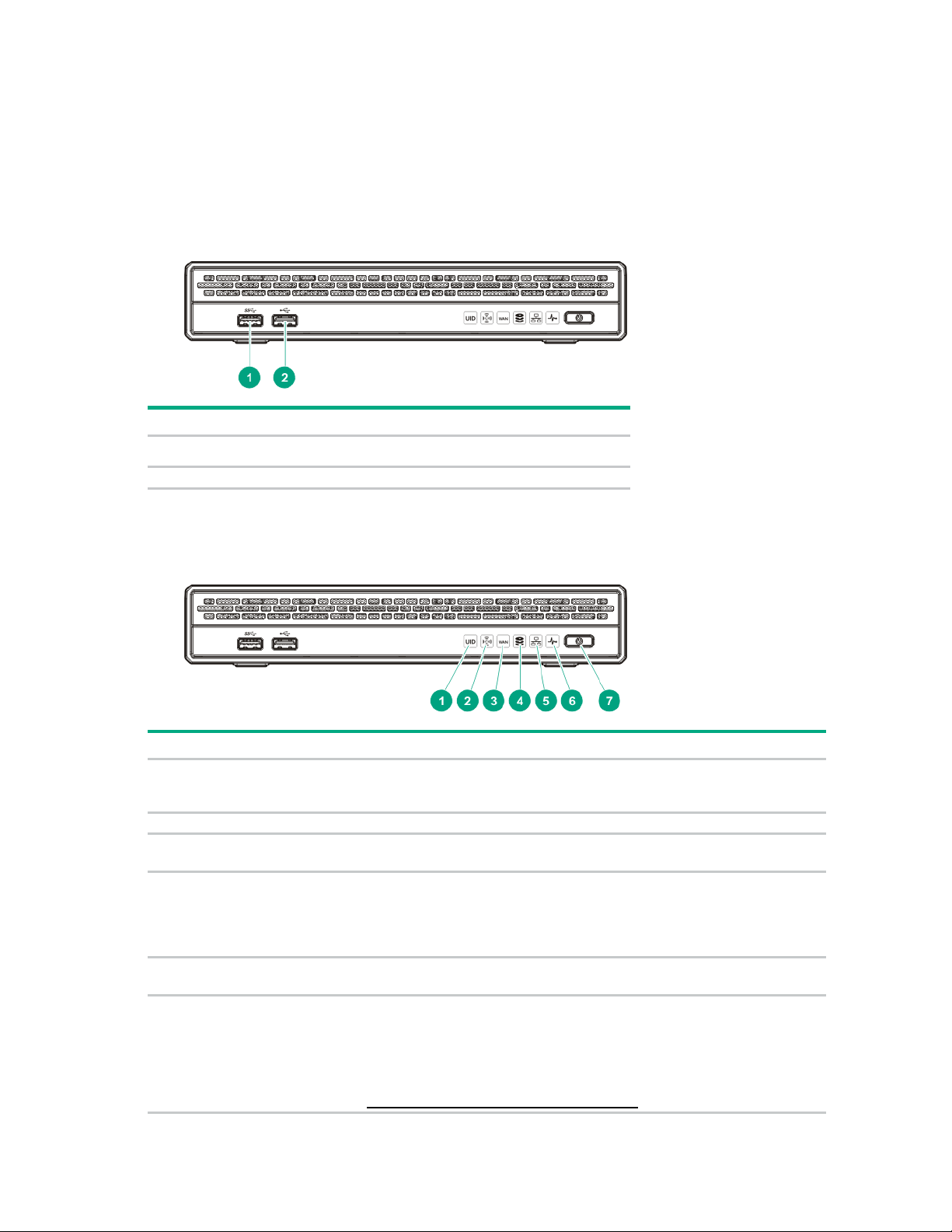
Component identification
USB 3.0 connector
2
USB 2.0 connector
UID LED
Solid blue = Activated
2
Wi-Fi LED
Reserved
WAN LED
Solid white = The server is able to make a valid WAN connection.
Drive LED
Flashing white = Ongoing drive activity
LAN LED
Solid white = The server is able to make a valid LAN connection.
Health LED
Solid white = Normal
Front panel components
Item Description
1
Front panel LEDs and button
Item Description Status
1
Flashing blue = Remote management or firmware upgrade in progress
Off = Deactivated
3
4
5
6
Off = The server is unable to make a valid WAN connection.
Off = No drive activity
This LED reflects the status of the drives installed in the server and in the
storage expansion unit.
Off = The server is unable to make a valid LAN connection.
Flashing amber = System degraded
Flashing red (1 flash per second) = System critical
If the health LED indicates a degraded or critical state, contact HPE
ProLiant Easy Connect Support
(https://support.prolianteasyconnect.com).
Component identification 5
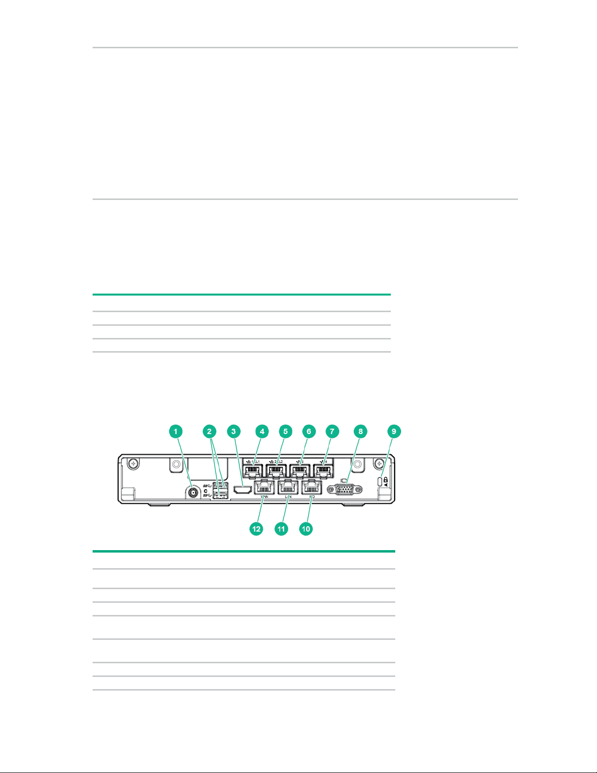
Power On/Standby
Solid white = System on
•
•
•
Subsystem
Front panel LED behavior
System board
1 flash
Processor
2 flashes
Memory
3 flashes
Power adapter connector
2
USB 3.0 connectors (2)
3
Reserved
LAN 1 connector for a single-server system/Cluster 1 connector
LAN 2 connector for a single-server system/Cluster 2 connector
6
LAN 3 connector*
7
LAN 4 connector or iLO crossover connector*
7
button and system
power LED
Flashing white = Performing power on sequence
Solid red = System in standby
Flashing red = Unsuccessful power on sequence.
When the 120 W power adapter is connected to a server that is attached to
a storage expansion unit, the system power LED flashes red. Replace the
120 W power adapter with the 180 W power adapter that shipped with the
storage expansion unit option kit.
Off = No power present
If the system power LED is off, verify the following conditions:
Facility power is present.
The power adapter is connected to the server.
The power cord is attached to the adapter and is plugged into a power
source.
When all LEDs described in this table flash simultaneously, a power fault has occurred. For more
information, see "Front panel LED power fault codes (on page 6)."
Front panel LED power fault codes
The following table provides a list of power fault codes, and the subsystems that are affected. Not all
power faults are used by all servers.
Rear panel components
For more information, see "Front panel LEDs and button (on page 5)."
Item Description
1
4
for a clustered system*
5
for a clustered system*
Component identification 6
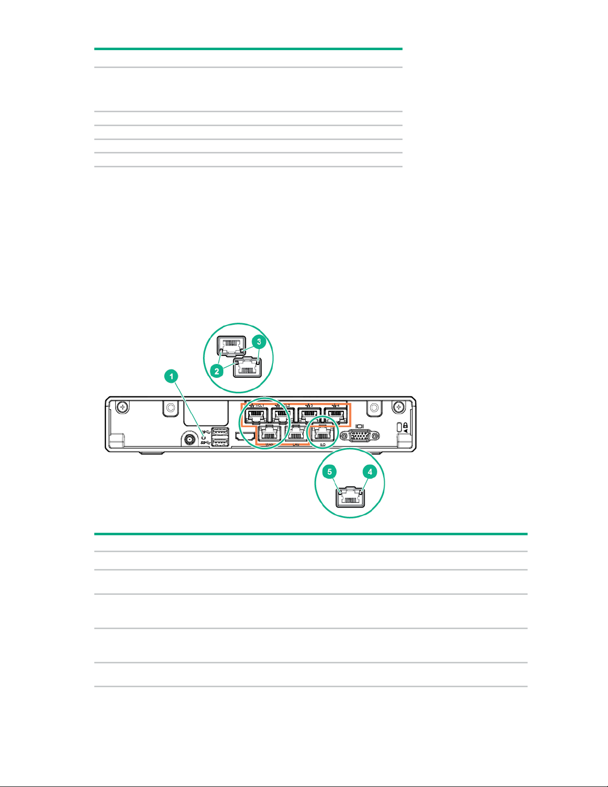
Item Description
Video connector
9
Kensington security slot
10
Dedicated iLO management connector
11
LAN connector
12
WAN connector
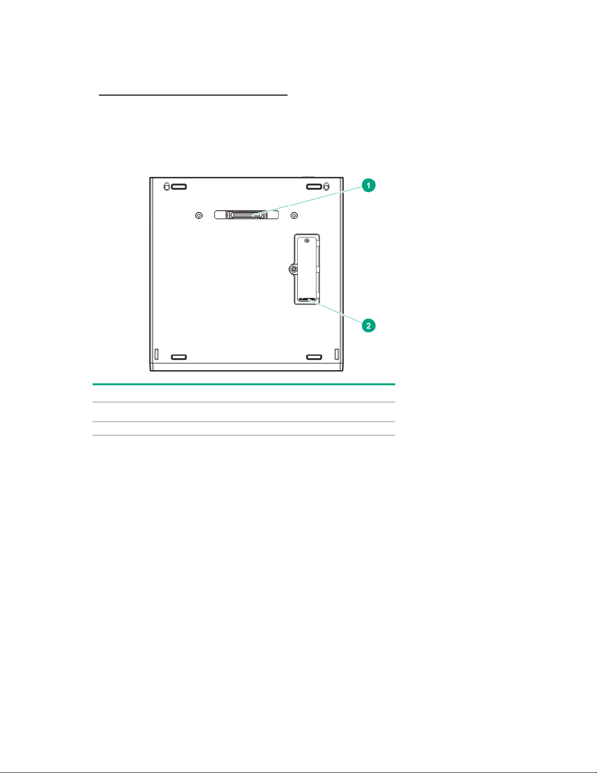
Reset button
Enter server recovery mode (on page 8).
NIC link LED
Green = Network link
NIC activity LED
Solid green = Link to network
Dedicated iLO activity
Solid green = Link to network
Dedicated iLO link LED
Green = Network link
8
* These connectors are present in the communication board option ("Installing the communication board" on page
37).
To reduce the risk of electric shock, fire, or damage to the
equipment, only devices that are made of fire-retardant material
can be connected to this video connector (VGA).
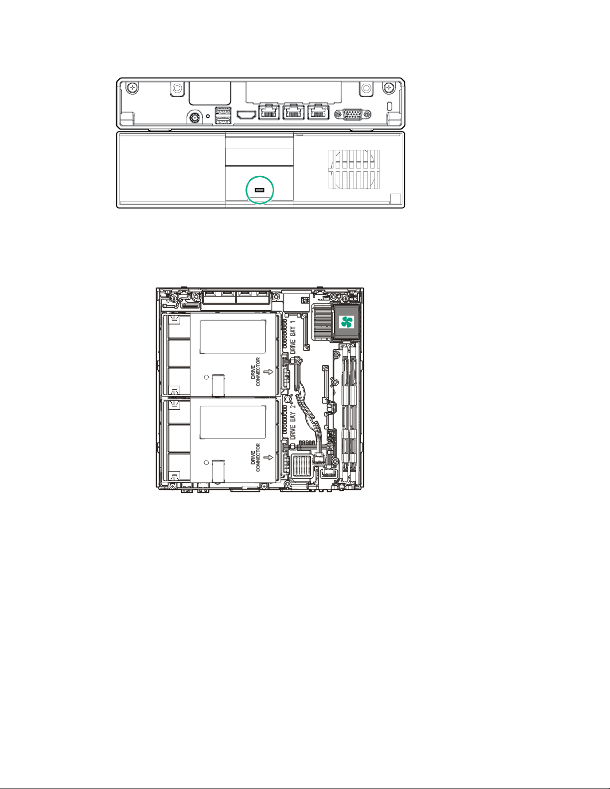
QR code label
A QR code label is located in the server rear panel. Use your mobile device to scan the QR code label to
display the server mobile product page. This page contains links to server setup information, spare part
numbers, QuickSpecs, troubleshooting resources, and other useful product links.
Rear panel LEDs and button
Item Description Status
1
2
3
4
5
LED
Off = No network link
Flashing green = Network active
Off = No network activity
Flashing green = Network active
Off = No network activity
Off = No network link
Component identification 7
Recovery mode
Dock connector (for storage expansion unit installation)
2
M.2 SSD compartment
Do not initiate recovery mode unless directed by HPE ProLiant Easy Connect Support
(https://support.prolianteasyconnect.com).
During recovery mode, the system will first attempt to perform a graceful shutdown of the operating
system (soft reset). If the soft reset attempt fails, the system will proceed to a hard reset.
Bottom components
Item Description
1
Component identification 8

System board components
1
System battery
2
Reserved
3
Fan connector
4
Channel 1 DIMM slot
5
Channel 2 DIMM slot
6
Drive 2 SATA connector
7
Drive 1 SATA connector
8
Communication board connector
9
Drive 2 power connector
10
System maintenance switch
11
Ambient temperature sensor connector
12
Drive 1 power connector
Position
Default
Function
Off
Off = iLO 4 security is enabled.
Off
Off = System configuration can be changed.
S3
Off
Reserved
Item Description
System maintenance switch
Do not change any of the system maintenance switch settings unless directed by HPE ProLiant Easy
Connect Support (https://support.prolianteasyconnect.com).
S1
S2
On = iLO 4 security is disabled.
On = System configuration is locked.
Component identification 9
Position
Default
Function
S4
Off
Reserved
Off
Off = Power-on password is enabled.
Off
Off = No function
S11, and S12
—
Reserved
S5
S6
S7, S8, S9, S10,
You can access the redundant ROM by setting S1, S5, and S6 to On.
When the system maintenance S6 switch is set to the On position, the system will erase all system
configuration settings from both CMOS and NVRAM on the next reboot. Clearing CMOS, NVRAM, or both
delete configuration information. Be sure to configure the server properly to prevent data loss.
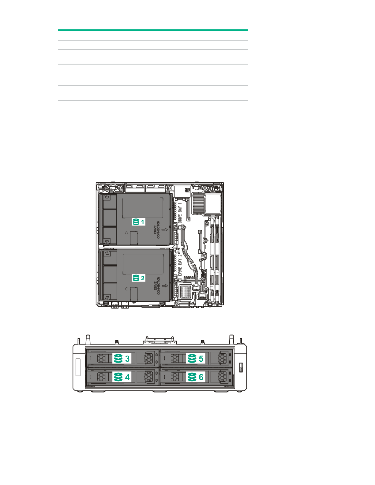
Drive numbering
• Drive numbering for the server
On = Power-on password is disabled.
On = ROM reads system configuration as
invalid.
• Drive numbering for the storage expansion unit
Component identification 10

Kensington security slot locations
• Kensington security slot for a server in the desktop position—Use a Kensington cable lock.
• Kensington security slot for a server installed in the cradle—Use a Kensington cable lock.
• Kensington security slot in the wall mount—Use a Kensington noncable lock or a cable lock that
includes a wall mount anchor.
Component identification 11
• Kensington security slot in the storage expansion unit—Use a Kensington cable lock.
Fan location
• Fan location in the server
Component identification 12
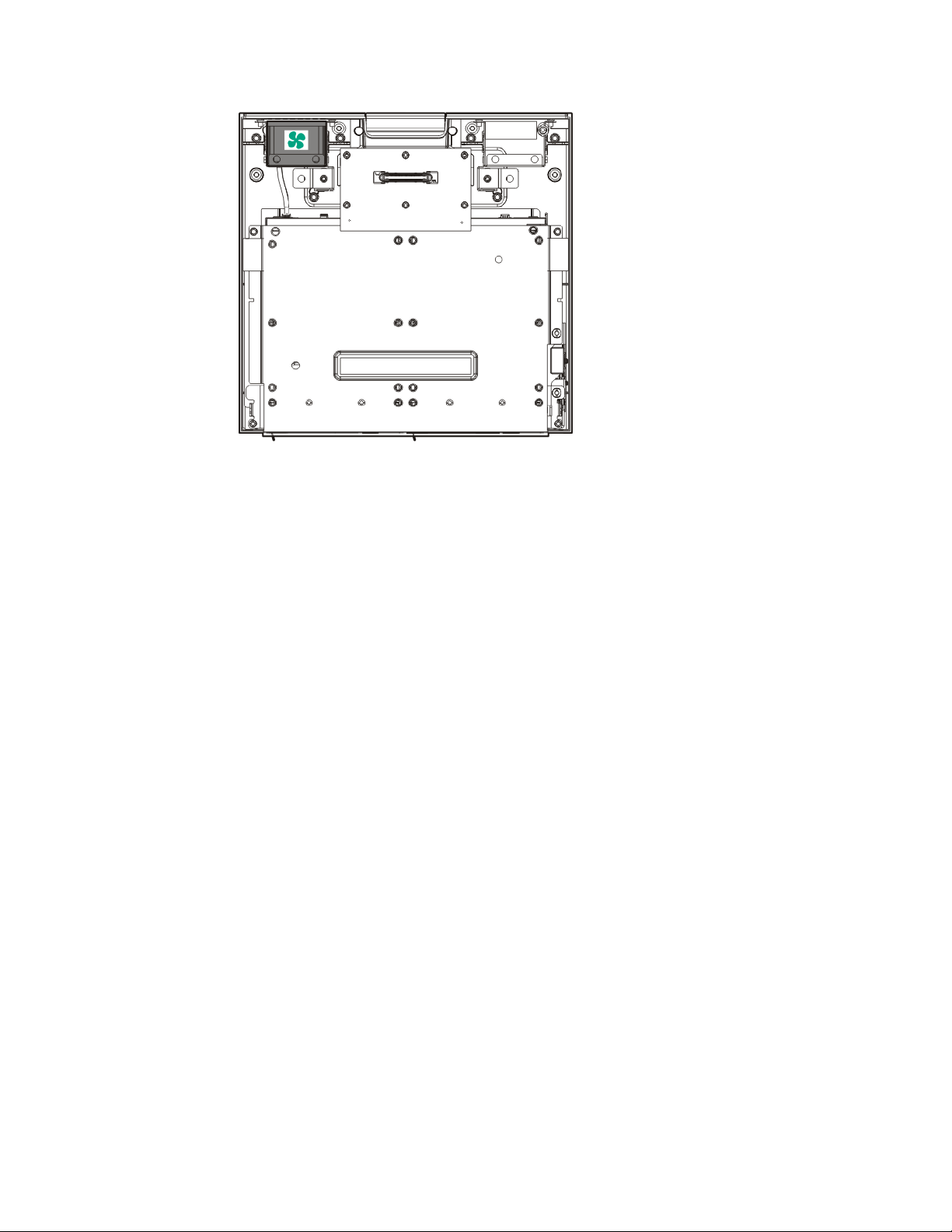
• Fan location in the storage expansion unit
Component identification 13

Operations
To reduce the risk of personal injury, electric shock, or damage to the equipment,
To prevent improper cooling and thermal damage, do not operate the server with
Server warnings and cautions
WARNING:
remove the power cord to remove power from the server. Pressing the Power On/Standby
button does not shut off system power completely. Portions of the power supply and some
internal circuitry remain active until AC power is removed.
WARNING: To reduce the risk of electric shock, fire, or damage to the equipment, only
display devices that are qualified to be made of fire-retardant material must be connected to
the video connector (VGA) on the rear panel.
WARNING: To reduce the risk of personal injury from hot surfaces, allow the drives and the
internal system components to cool before touching them.
CAUTION:
the access panel and the M.2 SSD compartment cover open or removed.
CAUTION: To prevent improper cooling and thermal damage, do not operate the server or
the storage expansion unit unless all device bays are populated with either a component or a
blank.
CAUTION: To prevent damage to electrical components, take the appropriate anti-static
precautions before beginning any installation, removal, or replacement procedure. Improper
grounding can cause electrostatic discharge.
Hardware operations reminder
The following hardware operations must be carried out according to service installation, upgrade, and
maintenance instructions available in the server user documents (http://www.hpe.com/info/EC-docs) or
from HPE ProLiant Easy Connect Support (https://support.prolianteasyconnect.com).
Power up procedure
Power up a single-server system
1. Press the Power On/Standby button.
The server exits standby mode and full power is applied to the system.
Power up a clustered system
2. Verify that the system power LED on the server is white ("Front panel LEDs and button" on page 5).
1. Press the Power On/Standby button on both servers within 5 minutes of each other.
The servers exit standby mode and full power is applied to the systems.
Operations 14

2.
Verify that the system power LEDs on both servers are white ("Front panel LEDs and button" on
page 5).
Power down procedure
Prerequisites
1. Notify Hewlett Packard Enterprise of any planned power down to ensure the orderly shutdown of
server services.
To contact Hewlett Packard Enterprise, see the HPE ProLiant Easy Connect Support
(https://support.prolianteasyconnect.com).
2. Verify that the server data has been recently backed up.
You can view the current backup status from the User Control Console Dashboard ("User Control
Console" on page 44). For more information on this console, see the HPE ProLiant Easy Connect
User Control Console Guide on the Hewlett Packard Enterprise website
Power down a single-server system
(http://www.hpe.com/support/EC-UCCG).
1. Do one of the following:
o To initiate a controlled shutdown of applications and the OS, press and release the Power
On/Standby button.
o To force a system shutdown if an application or the OS stops responding, press and hold the
Power On/Standby button for more than four seconds.
The LAN, WAN, and WiFi LEDs on the server flash to indicate that the server shutdown is in
progress. If the server does not power down after the LAN, WAN, and WiFi LEDs stop flashing,
contact the HPE ProLiant Easy Support (https://support.prolianteasyconnect.com).
2. Verify that the system power LED on the server is red ("Front panel LEDs and button" on page 5).
A red system power LED means that the server is in standby mode. Auxiliary power is still present in
the system in this mode.
Power down a clustered system
1. Do one of the following:
o Before performing hardware maintenance on one of the servers in a clustered pair, press and
release the Power On/Standby button on the server that requires maintenance. This action will
initiate a controlled shutdown of applications and the OS.
In this scenario, the Managed Hybrid Services switches over to the remaining powered on server
to ensure that there is no interruption to normal user operations.
o Before moving a clustered pair of servers or when preparing for a planned power outage on the
site, press and release the Power On/Standby button on both servers within 30 seconds of each
other. This action will initiate a controlled shutdown of applications and the OS.
The LAN, WAN, and WiFi LEDs on both servers flash to indicate that the server shutdown is in
progress. If the system does not power down after the LAN, WAN, and WiFi LEDs stop flashing,
contact the HPE ProLiant Easy Connect Support (https://support.prolianteasyconnect.com).
2. Verify that the system power LED on the server or servers where the power button was pressed is
red ("Front panel LEDs and button" on page 5).
A red system power LED means that the server is in standby mode. Auxiliary power is still present in
the system in this mode.
Operations 15

Prepare the server for hardware installation or removal
1. Verify that the server data has been recently backed up.
2. Do one of the following:
o Power down a single-server system (on page 15).
o Power down a clustered system (on page 15).
3. Disconnect the power cord from the AC source, and then disconnect the power adapter from the
server.
4. Disconnect all peripheral cables from the server.
5. If installed, unlock and remove the Kensington security lock.
For more information, see the Kensington security lock documentation.
Prepare the server for operation
1. If removed, install the Kensington security lock.
For more information, see the Kensington security lock documentation.
2. Connect all peripheral cables to the server.
3. Connect the power adapter to the server, and then connect the power cord to the AC source.
4. Secure the power cord and rear panel cables based on the standard cable management practices.
5. Do one of the following:
o Power up a single-server system (on page 14).
o Power up a clustered system (on page 14).
Remove the server from the mounting/docking hardware
If the server is installed in a cradle, wall mount, or storage expansion unit:
• Remove the server from the cradle (on page 16).
• Remove the server from the wall mount (on page 17).
Remove the server from the cradle
• Remove the server from the storage expansion unit (on page 17).
1. Open the latches on the cradle.
Operations 16
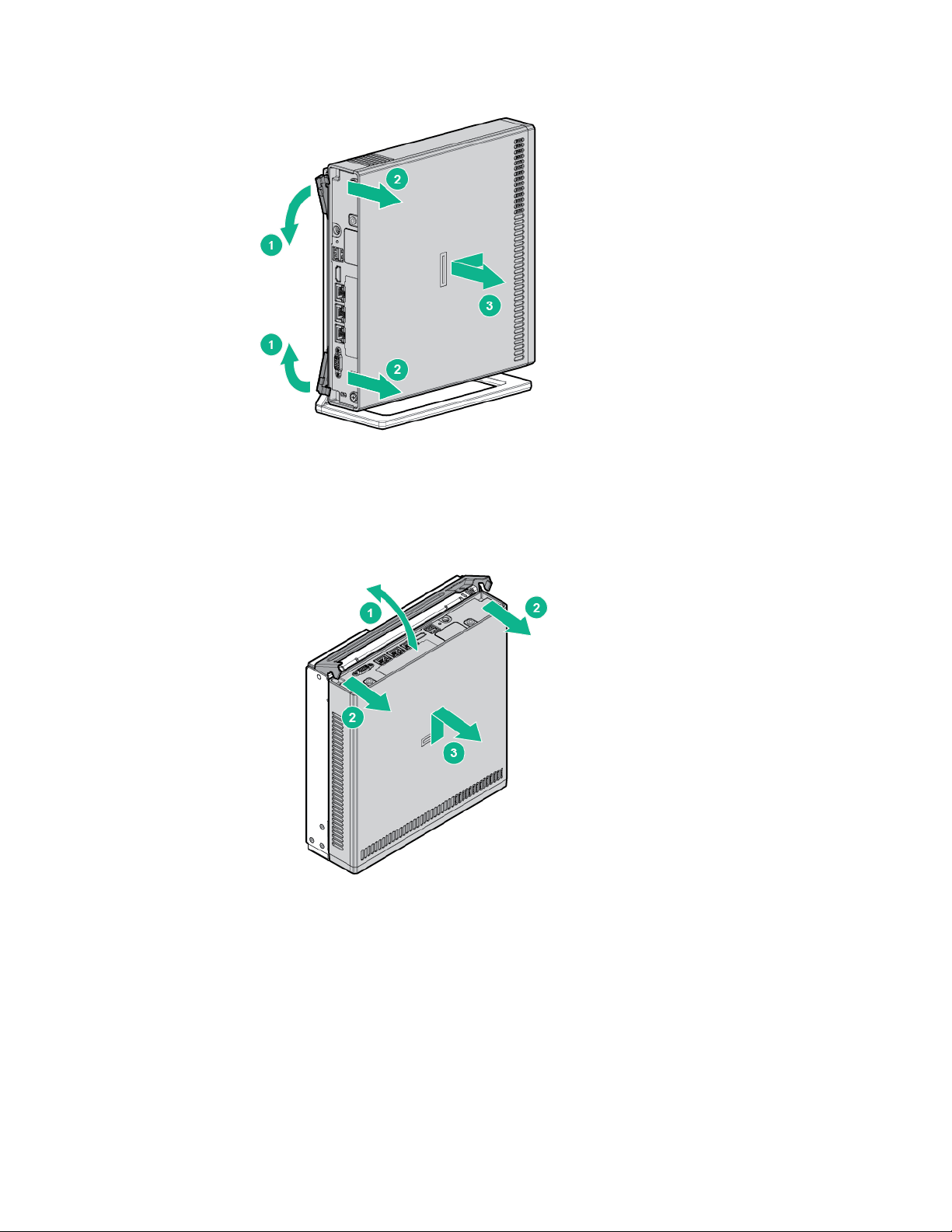
2.
Remove the server from the cradle.
Remove the server from the wall mount
1. Open the wall mount latch.
2. Remove the server from the wall mount.
Remove the server from the storage expansion unit
Before you perform this procedure, make sure that you have a No. 2 Phillips screwdriver available.
1. Hold the top side of the server and the bottom side of the storage expansion unit, and then carefully
turn the assembly over to access the bottom side of the storage expansion unit.
2. Remove the server from the storage expansion unit:
a. Pull the latch on the rear of the storage expansion unit.
b. Loosen the captive screws.
Operations 17
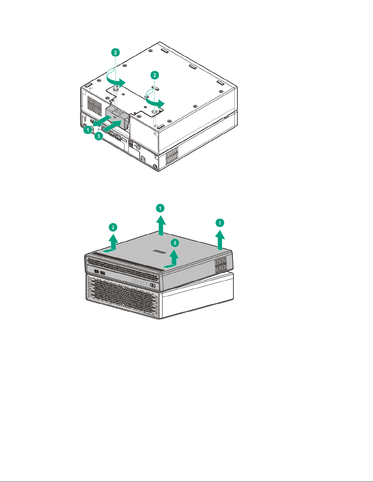
c.
Push the latch back in place.
d. Return the assembly to an upright position.
e. Remove the server from the storage expansion unit.
Remove the access panel
Before you perform this procedure, make sure that you have a No. 2 Phillips screwdriver available.
1. Loosen the captive screws.
Operations 18
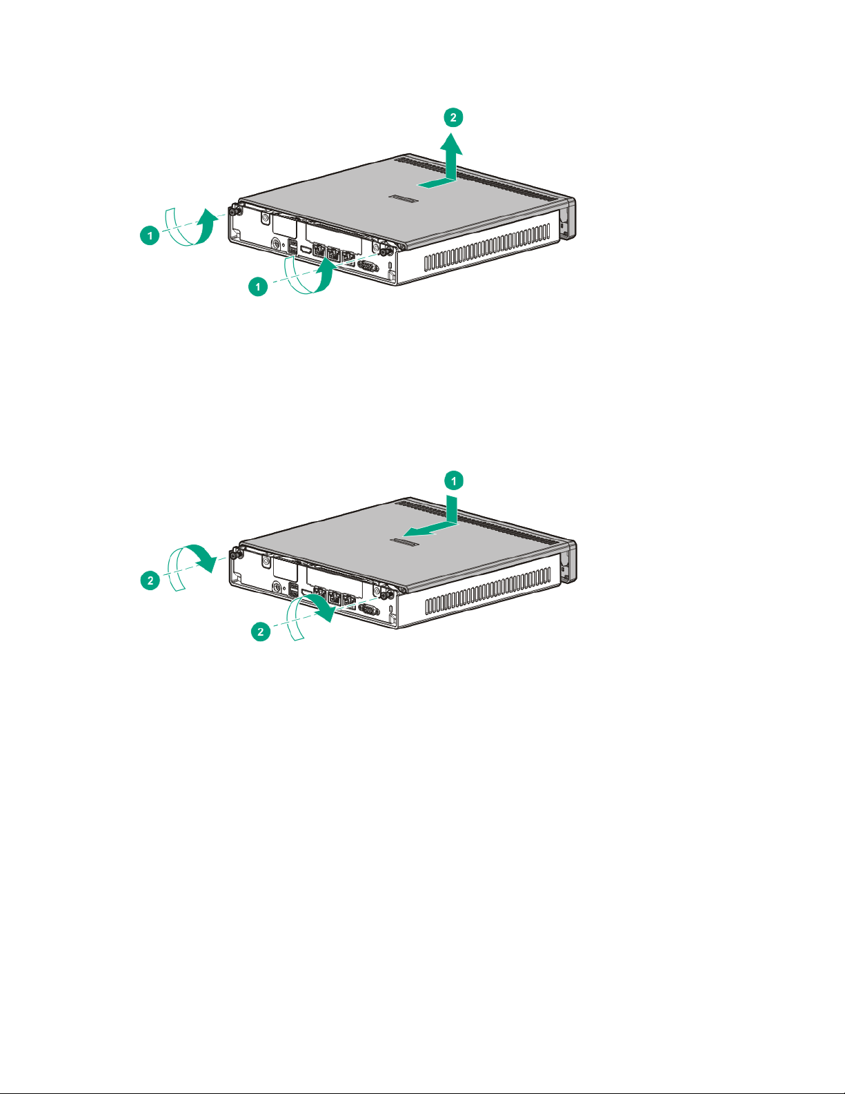
2.
Slide the access panel toward the front of the server, and then lift it from the server.
Install the access panel
Before you perform this procedure, make sure that you have a No. 2 Phillips screwdriver available.
1. Slide the access panel toward the rear of the server.
2. Tighten the captive screws.
Operations 19

Setup
overload the AC supply branch circuit that provides power to the server. Consult the electrical
Optimum environment
When installing the server, select a location that meets the environmental standards described in this
Operating environmental requirements
section.
The server may be located in an office space or a purpose-made equipment room. The location must:
• Comply with local health and safety regulations.
• Be clean, tidy, and free of excessive dust and vibration and have an ambient temperature of between
0°C to 40°C (32°F to 104°F).
• Make sure that there is a minimum clearance of 30 cm (11.81 in) around the ventilation openings.
The server draws in cool air through the ventilation openings on the left side, and expels warm air
through the ventilation openings on right side. Do not block these openings. Failure to observe this
caution will result in improper airflow and insufficient cooling that can lead to thermal damage.
• Offer space, ideally 1.00 m (3.28 ft) at the front and rear, for an authorized technician to access the
server and cable it.
• Possess a reliable power source no more than 1.50 m (4.92 ft) from the server location or, ideally be
protected by a UPS.
• Be in an area in which the server cannot easily be disconnected from their power source or by staff
such as housekeeping.
• Not be adjacent to or underneath any area or piece of equipment where liquid is stored.
• Not be in a place where the server might be bumped, scratched, or disturbed.
• Be within an area that is ideally locked or at minimum not accessible by unauthorized personnel.
• Be within patching distance, directly or via cable management cross-patches, of the location of the
WAN connection and the switch that supplies the office/room floor ports.
Power requirements
Installation of this equipment must comply with local and regional electrical regulations governing the
installation of information technology equipment by licensed electricians. This equipment is designed to
operate in installations covered by NFPA 70, 1999 Edition (National Electric Code) and NFPA-75, 1992
(code for Protection of Electronic Computer/Data Processing Equipment). For electrical power ratings on
options, refer to the product rating label or the user documentation supplied with that option.
WARNING: To reduce the risk of personal injury, fire, or damage to the equipment, do not
authority having jurisdiction over wiring and installation requirements of your facility.
CAUTION: Protect the server from power fluctuations and temporary interruptions with a
regulating uninterruptible power supply. This device protects the hardware from damage
caused by power surges and voltage spikes and keeps the system in operation during a power
failure.
Setup 20

When installing more than one server, you might need to use additional power distribution devices to
provide power to all devices safely. Observe the following guidelines:
• Balance the server power load between available AC supply branch circuits.
• Do not allow the overall system AC current load to exceed 80% of the branch circuit AC current
rating.
• Do not use common power outlet strips for this equipment.
• Provide a separate electrical circuit for the server.
Electrical grounding requirements
The server must be grounded properly for proper operation and safety. In the United States, you must
install the equipment in accordance with NFPA 70, 1999 Edition (National Electric Code), Article 250, as
well as any local and regional building codes. In Canada, you must install the equipment in accordance
with Canadian Standards Association, CSA C22.1, Canadian Electrical Code. In all other countries, you
must install the equipment in accordance with any regional or national electrical wiring codes, such as the
International Electrotechnical Commission (IEC) Code 364, parts 1 through 7. Furthermore, you must be
sure that all power distribution devices used in the installation, such as branch wiring and receptacles, are
listed or certified grounding-type devices.
Because of the high ground-leakage currents associated with multiple servers connected to the same
power source, Hewlett Packard Enterprise recommends the use of a PDU that is either permanently wired
to the building’s branch circuit or includes a nondetachable cord that is wired to an industrial-style plug.
NEMA locking-style plugs or those complying with IEC 60309 are considered suitable for this purpose.
Using common power outlet strips for the server is not recommended.
Managed Hybrid Service reminders
• The Managed Hybrid Service contract includes all of the required onsite server maintenance,
provided that the server has been supplied as a part of the HPE Easy Connect solution. Do not
attempt to open the chassis or tamper with it in any way. Any such action is a breach of the Managed
Hybrid Service contract. Only qualified personnel authorized by the MSP supplying the server must
power on the server and connect it to the WAN and LAN on the user site.
• Repeatedly cycling the power or shutting down the server at regular or irregular intervals is
discouraged for the following reasons:
o These actions put the server under thermal stress as it warms up and cools down. This thermal
stress can reduce the server lifecycle.
o These actions prevent the server from being monitored remotely, which in turn jeopardizes the
achievement of service level commitments.
o These actions can lead to data corruption, particularly on a server cluster. If data corruption
occurs, data from the backup will be used to restore the data. This backup data might not match
the most recently changed data before the data corruption.
• Notify the MSP at least seven (7) days in advance of any planned electrical work that might result in
a power interruption. This notification will allow Hewlett Packard Enterprise to arrange for an orderly
shutdown of the server during the duration of the electrical work.
Prerequisites for preparing the server for installation
Before installation, the user must:
• Verify that the optimum environmental requirements are satisfied ("Operating environmental
requirements" on page 20).
Setup 21

• Confirm that the installation engineer understands how to integrate the server into the user network,
in particular from an IP addressing perspective and from a domain perspective.
• Prepare Ethernet cables of an appropriate length for each of the LAN, WAN, and remote
management (iLO) connections.
• Verify that there are sufficient ports available on the devices to which the server will be connected
(for example, router, LAN switch).
Identify the contents of the server shipping carton
Unpack the server shipping carton and locate the materials and documentation necessary for installing
the server.
The contents of the server shipping carton include:
• Server
• Power adapter (120 W)
• Power cord
• Printed setup documentation
Place the server in the intended location
Place the server in the intended location provided that this location fully satisfies the requirements for
optimum environment ("Operating environmental requirements" on page 20).
Do not connect the power cord to the power source yet.
Install the server on the mounting/docking hardware
If you intend to set up the server in a cradle, wall mount, or storage expansion unit, do one of the following:
• Install the server in the cradle ("Installing the server in the cradle" on page 23).
• Install the server in the wall mount ("Installing the server in the wall mount" on page 24).
• Install the server on the storage expansion unit ("Installing the server on the storage expansion unit"
on page 34).
Do not connect the power cord to the power source yet.
Perform the initial server installation
For detailed server installation procedures, go to the HPE ProLiant Easy Connect Support Portal
(https://support.prolianteasyconnect.com).
For network cabling procedures, see "Rear panel components (on page 6)" for the location of the server
Ethernet connectors.
Register the product
To experience quicker service and more efficient support, register the product at the Hewlett Packard
Enterprise Product Registration website (http://www.hpe.com/info/register).
Setup 22
 Loading...