

Page 1

ProLiant DL760 Servers
User Guide
First Edition (March 2001)
Part Number 173774-001
Compaq Computer Corporation
Page 2

Notice
© 2001 Compaq Computer Corporation
COMPAQ, the Compaq logo, Compaq Insight Manager, ProLiant, ROMPaq, and SmartStart Registered
in U. S. Patent and Trademark Office. ActiveAnswers is a trademark of Compaq Information
Technologies Group, L.P. in the United States and other countries.
Microsoft, MS-DOS, Windows, Windows NT are trademarks of Microsoft Corporation.
Intel, Pentium, Celeron, and Xeon are trademarks of Intel Corporation.
UNIX is a trademark of The Open Group.
All other product names mentioned herein may be trademarks of their respective companies.
Compaq shall not be liable for technical or editorial errors or omissions contained herein. The
information in this document is provided “as is” without warranty of any kind and is subject to change
without notice. The warranties for Compaq products are set forth in the express limited warranty
statements accompanying such products. Nothing herein should be construed as constituting an
additional warranty.
Compaq ProLiant DL760 Servers User Guide
First Edition (March 2001)
Part Number 173774-001
Page 3

Contents
About This Guide
Purpose and Scope......................................................................................................ix
Important Safety Information .....................................................................................ix
Text Conventions.........................................................................................................x
Symbols in Text..........................................................................................................xi
Symbols on Equipment..............................................................................................xii
Rack Stability .......................................................................................................... xiii
Access Panel Label and Indicators ...........................................................................xiv
Getting Help ..............................................................................................................xv
Compaq Technical Support ................................................................................xv
Compaq Website.................................................................................................xv
Compaq Authorized Reseller.............................................................................xvi
Related References ............................................................................................xvi
Chapter 1
Server Features
Compaq ProLiant DL760 Servers............................................................................ 1-1
Server Components.................................................................................................. 1-2
New Technology...................................................................................................... 1-4
PCI-X Support.................................................................................................. 1-4
Compaq ROM-Based Setup Utility Support .................................................... 1-4
Faster Processor Support .................................................................................. 1-4
Page 4

iv Compaq ProLiant DL760 Servers User Guide
Server Features
continued
Standard Features..................................................................................................... 1-5
Processor and Redundant Processor Power Modules ....................................... 1-5
System Memory................................................................................................ 1-5
Cache Accelerator............................................................................................. 1-5
Expansion Slots................................................................................................. 1-6
Network Controller........................................................................................... 1-6
PCI Hot Plug..................................................................................................... 1-7
Disk Controller .................................................................................................1-7
Internal Hot-Plug Drive Bays ...........................................................................1-7
Fixed Internal Media Drive Bays...................................................................... 1-7
Video................................................................................................................. 1-8
Redundant Hot-Plug Power Supplies................................................................ 1-8
Redundant Hot-Plug Fan................................................................................... 1-8
Supported Interfaces ......................................................................................... 1-9
Optional Features ..................................................................................................... 1-9
Server Configuration and Management Features................................................... 1-10
Compaq SmartStart......................................................................................... 1-10
Compaq ROM-Based Setup Utility ................................................................ 1-11
Compaq Remote-Flash Redundant ROM ....................................................... 1-12
Microsoft Windows 2000 Utilities.................................................................. 1-12
Microsoft Windows NT Utilities ....................................................................1-13
Novell NetWare Utilities ................................................................................ 1-13
SCO UnixWare Utilities ................................................................................. 1-14
Compaq Insight Manager/Insight Manager XE.............................................. 1-14
Compaq Web-Enabled Server Management .......................................................... 1-15
Compaq Integrated Management Log............................................................. 1-15
Compaq Integrated Management Display....................................................... 1-15
Diagnostic Tools .................................................................................................... 1-16
Security Features.................................................................................................... 1-17
Software Security............................................................................................ 1-17
Hardware Security .......................................................................................... 1-17
Routine Maintenance ............................................................................................. 1-18
Warranty ................................................................................................................ 1-18
Chapter 2
Installing the Server in a Rack
Rack Installation Overview...................................................................................... 2-2
Selecting a Site......................................................................................................... 2-3
Space Requirements.......................................................................................... 2-3
Power Requirements......................................................................................... 2-4
Grounding Requirements.................................................................................. 2-8
Temperature Requirements............................................................................... 2-9
Airflow Requirements..................................................................................... 2-10
Page 5

Installing the Server in a Rack
continued
Shipping Box Contents.......................................................................................... 2-11
Removing the Shipping Safeguards....................................................................... 2-12
Install any Expansion Boards or Optional Features............................................... 2-14
Rack Warnings and Precautions ............................................................................ 2-15
Server Warnings and Precautions.......................................................................... 2-16
Installing the Server in a Rack............................................................................... 2-17
Lightening the Chassis.................................................................................... 2-17
Attaching the Inner Slide Rails to the Server.................................................. 2-18
Attaching the Outer Slide Rail Assembly to the Rack.................................... 2-19
Sliding the Server into the Rack ..................................................................... 2-24
Attaching the Cable Management Assembly.................................................. 2-27
Chapter 3
Server Access
Server Access Panel and Modules ........................................................................... 3-2
Accessing the I/O Module ................................................................................ 3-3
Removing the I/O Module................................................................................ 3-4
Removing the Processor and Memory Module ................................................ 3-7
Processor Serial Number .................................................................................. 3-8
Removing the Media Module........................................................................... 3-9
Media Module Components ........................................................................... 3-11
Contents v
Chapter 4
Installing Hardware Options - Server Power Off
Installing a Pentium III Xeon Processor and Processor Power Module................... 4-2
Installing the Cache Accelerator.............................................................................. 4-9
Dual Inline Memory Modules (DIMMs) ............................................................... 4-12
Adding or Replacing Memory........................................................................ 4-12
External Storage Devices....................................................................................... 4-15
Non-Hot-plug I/O Expansion Boards .................................................................... 4-17
Locating the I/O Expansion Slots................................................................... 4-18
PCI-X and PCI Bus Distribution Guidelines .................................................. 4-19
Adding Non-Hot Plug Expansion Boards....................................................... 4-20
Installing the Remote Insight Lights-Out Edition.................................................. 4-22
Installing the Integrated Array Bypass .................................................................. 4-26
Chapter 5
Installing Hardware Options - Hot Pluggable
Mass Storage............................................................................................................ 5-2
SCSI Hard Drive Installation Guidelines.......................................................... 5-3
Installing a Hot-Plug SCSI Hard Disk Drive.................................................... 5-4
Removing a Hot Plug SCSI Hard Disk Drive................................................... 5-5
Page 6

vi Compaq ProLiant DL760 Servers User Guide
Installing Hardware Options - Hot Pluggable
continued
Installing a Hot-Plug Power Supply....................................................................... 5-10
PCI Hot-Plug I/O Expansion Boards ..................................................................... 5-14
Locating the I/O Expansion Slots ................................................................... 5-15
PCI Hot Plug LED Indicators ......................................................................... 5-16
PCI Hot Plug Operating System Support........................................................ 5-18
PCI-X and PCI Bus Distribution Guidelines ..................................................5-25
Adding PCI Hot Plug Expansion Boards........................................................ 5-26
Removing or Replacing a PCI Hot Plug Expansion Board............................. 5-30
Replacing Hot-Plug Fans ....................................................................................... 5-31
Chapter 6
Cabling the Server
Cabling the Server.................................................................................................... 6-2
Chapter 7
Server Power
System Power........................................................................................................... 7-2
Power Supply LED Indicators .......................................................................... 7-3
Power Supplies ................................................................................................. 7-4
System Interconnect Status LED Indicators............................................................. 7-5
Powering Up the Server ........................................................................................... 7-7
Integrated Management Display ....................................................................... 7-7
Powering Down the Server ...................................................................................... 7-9
Chapter 8
Configuring the Server
Setting Up the SCSI Array....................................................................................... 8-2
Features............................................................................................................. 8-2
Option ROM-Based Array Configuration Utility ............................................. 8-4
Array Configuration Utility ..............................................................................8-5
Starting the Compaq Array Configuration Utility............................................. 8-6
Errors and Warnings ......................................................................................... 8-8
Alternate Sources of the Array Configuration Utility....................................... 8-9
Installing the Operating System............................................................................. 8-10
Compaq ROM-Based Setup Utility ................................................................ 8-10
Operating System—Purchased Separately...................................................... 8-11
Operating System—Factory Installed............................................................. 8-12
Page 7

Chapter 9
Integrated Management Log
Multiple Ways of Viewing the Log ......................................................................... 9-2
Integrated Management Display.............................................................................. 9-2
Configuring the Integrated Management Display............................................. 9-2
Customizing Management Display Fields........................................................ 9-5
Standard Integrated Management Display Fields............................................. 9-9
Navigating the Menus............................................................................................ 9-10
Normal Run-time Behavior ............................................................................ 9-10
Display Symbols............................................................................................. 9-11
Navigation ...................................................................................................... 9-12
System Behavior with Error Events................................................................ 9-13
Menu Structure ............................................................................................... 9-13
Compaq Insight Manager....................................................................................... 9-15
Viewing the Event List................................................................................... 9-15
Printing the Event List.................................................................................... 9-16
Compaq Survey Utility.......................................................................................... 9-16
Appendix A
Regulatory Compliance Notices
Regulatory Compliance Identification Numbers .....................................................A-1
Federal Communications Commission Notice ........................................................A-1
Class A Equipment...........................................................................................A-2
Modifications....................................................................................................A-3
Cables ...............................................................................................................A-3
Canadian Notice (Avis Canadien) ...........................................................................A-3
Class A Equipment...........................................................................................A-3
Mouse Compliance Statement .................................................................................A-3
European Union Notice ...........................................................................................A-4
Japanese Notice .......................................................................................................A-4
Taiwanese Notice.....................................................................................................A-4
Laser Devices...........................................................................................................A-5
Laser Safety Warnings......................................................................................A-5
Compliance with CDRH Regulations...............................................................A-5
Compliance with International Regulations......................................................A-5
Laser Product Label..........................................................................................A-6
Laser Information .............................................................................................A-6
Power Cords ............................................................................................................A-6
Battery Replacement Notice....................................................................................A-7
Contents vii
Appendix B
Electrostatic Discharge
Grounding Methods.................................................................................................B-2
Page 8

viii Compaq ProLiant DL760 Servers User Guide
Appendix C
Server Error Messages
POST Error Messages..............................................................................................C-1
ADU Error Messages...............................................................................................C-1
Appendix D
LED Indicators and Switches
LED Indicators........................................................................................................ D-1
System LED Indicator...................................................................................... D-2
Auxiliary Power LED Indicator....................................................................... D-2
System Interconnect Status LED Indicators .................................................... D-3
Hot-Plug SCSI Hard Drive LED Indicators..................................................... D-5
Power Supply LED Indicators ......................................................................... D-7
Hot-Plug Fan LED Indicators .......................................................................... D-8
PCI Hot Plug LED Indicators .......................................................................... D-9
Switches ................................................................................................................ D-11
Processor Board Switches.............................................................................. D-11
Processor Board Bus/Core Frequency Ratio.................................................. D-12
I/O Board Switches........................................................................................ D-13
Appendix E
Troubleshooting Information
When the Server Does Not Start ..............................................................................E-2
Diagnosis Steps........................................................................................................E-4
Problems After Initial Boot.................................................................................... E-13
Compaq Remote-Flash Redundant ROM .......................................................E-15
Appendix F
Server Specifications
Appendix G
System Battery
Internal Battery ....................................................................................................... G-2
Index
Page 9
Purpose and Scope
This guide is designed to be used as step-by-step instructions for installation,
and as a reference for operation, troubleshooting, and future upgrades for
Compaq ProLiant™ DL760 servers.
WARNING: To reduce the risk of personal injury from electrical shock and
hazardous energy levels, only authorized service technicians should attempt to
repair this equipment. Improper repairs could create conditions that are
hazardous.
IMPORTANT: The installation of options and servicing of this product shall be performed
by individuals who are knowledgeable of the procedures, precautions, and hazards
associated with equipment containing hazardous energy circuits.
About This Guide
Important Safety Information
Before installing this product, read the Important Safety Information document
provided.
Page 10

x Compaq ProLiant DL760 Servers User Guide
Text Conventions
This document uses the following conventions to distinguish elements of text:
Keys Keys appear in boldface. A plus sign (+) between
USER INPUT User input appears in a different typeface and in
FILENAMES File names appear in uppercase italics.
two keys indicates that they should be pressed
simultaneously.
uppercase.
Menu Options,
Command Names,
Dialog Box Names
COMMANDS,
DIRECTORY NAMES,
and DRIVE NAMES
Type When you are instructed to type information, type
Enter When you are instructed to enter information, type
These elements appear in initial capital letters.
These elements appear in uppercase.
the information without pressing the Enter key.
the information and then press the Enter key.
Page 11
Symbols in Text
The following symbols are found in the text of this guide to indicate different
types of information.
IMPORTANT: Text set off in this manner presents clarifying information or specific
instructions.
NOTE: Text set off in this manner presents commentary, sidelights, or interesting points
of information.
About This Guide xi
WARNING: Text set off in this manner indicates that failure to follow directions
in the warning could result in bodily harm or loss of life.
CAUTION: Text set off in this manner indicates that failure to follow directions
could result in damage to equipment or loss of information.
Page 12
xii Compaq ProLiant DL760 Servers User Guide
Symbols on Equipment
The following symbols are placed on equipment to indicate the presence of
potentially hazardous conditions:
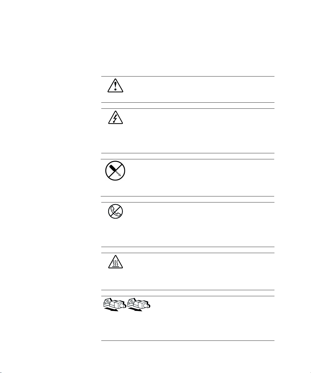
This symbol in conjunction with any of the following symbols indicates the
presence of a potential hazard. The potential for injury exists if warnings
are not observed. Consult your documentation for specific details.
This symbol indicates the presence of hazardous energy circuits or electric
shock hazards. Refer all servicing to qualified personnel.
WARNING: To reduce the risk of injury from electric shock hazards, do not
open this enclosure. Refer all maintenance, upgrades, and servicing to
qualified personnel.
This symbol indicates the presence of electric shock hazards. The area
contains no user or field serviceable parts. Do not open for any reason.
WARNING: To reduce the risk of injury from electric shock hazards, do
not open this enclosure.
This symbol on an RJ-45 receptacle indicates a Network Interface
Connection.
WARNING: To reduce the risk of electric shock, fire, or damage to the
equipment, do not plug telephone or telecommunications connectors into
this receptacle.
This symbol indicates the presence of a hot surface or hot component. If
this surface is contacted, the potential for injury exists.
WARNING: To reduce the risk of injury from a hot component, allow the
surface to cool before touching.
These symbols on power supplies or systems indicate the
equipment is supplied by multiple sources of power.
WARNING: To reduce the risk of injury from electric shock,
remove all power cords to completely disconnect power from
the system.
Page 13
Weight in kg
Weight in lb
Rack Stability
About This Guide xiii
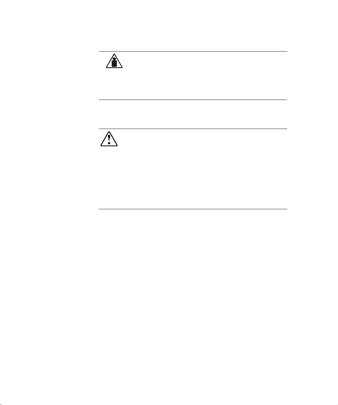
This symbol indicates that the component exceeds the recommended
weight for one individual to handle safely.
WARNING: To reduce the risk of personal injury or damage to the
equipment, observe local occupational health and safety requirements and
guidelines for manual material handling.
WARNING: To reduce the risk of personal injury or damage to the equipment,
be sure that:
■ The leveling jacks are extended to the floor.
■ The full weight of the rack rests on the leveling jacks.
■ The stabilizing feet are attached to the rack if it is a single rack installation.
■ The racks are coupled together in multiple rack installations.
■ Only one component is extended at a time. A rack may become unstable if
more than one component is extended for any reason.
Page 14
xiv Compaq ProLiant DL760 Servers User Guide
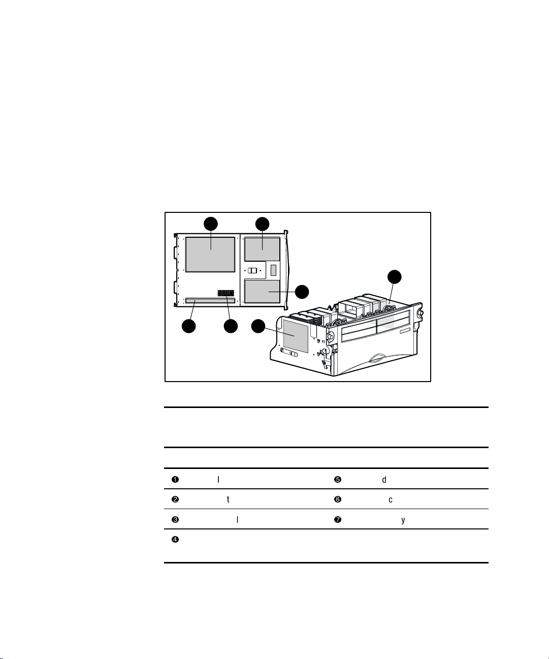
Access Panel Label and Indicators
A significant amount of server configuration and options installation
information is provided on the panel labels. As shown in Figure 1, these labels
are located on the top of the unit and on the sides of the Processor and
Memory Module. To access the appropriate label, see Chapter 3, “Server
Access.”
NOTE: These labels do not contain warning and caution information. Refer to this guide
or to the option documentation for the applicable warnings and cautions.
1
5 4
Figure 1. Location of labels and indicators
2
7
3
6
Table 1
Location of Labels and Indicators
Item Component Item Component
I/O board information
Options installation
Additional I/O information
Processor board configuration
Module access
System Interlock Status
Indicators
Memory installation
Page 15

Getting Help
If you have a problem and have exhausted the information in this guide, you
can get further information and other help in the following locations.
Compaq Technical Support
In North America, call the Compaq Technical Phone Support Center at
1-800-OK-COMPAQ. This service is available 24 hours a day, 7 days a week.
For continuous quality improvement, calls may be recorded or monitored.
Outside North America, call the nearest Compaq Technical Support Phone
Center. Telephone numbers for worldwide Technical Support Centers are
listed in the Worldwide Telephone Numbers booklet included with your
product or on the Compaq website. Access the Compaq website:
http://www.compaq.com
Be sure to have the following information available before you call Compaq:
■ Technical support registration number (if applicable)
■ Product serial number
About This Guide xv
■ Product model name and number
■ Applicable error messages
■ Add-on boards or hardware
■ Third-party hardware or software
■ Operating system type and revision level
■ Compaq Survey Utility Information
Compaq Website
The Compaq website has information on this product as well as the latest
drivers and Flash ROM images. You can access the Compaq website by
logging on to the Internet at
http://www.compaq.com
Page 16

xvi Compaq ProLiant DL760 Servers User Guide
Compaq Authorized Reseller
For the name of your nearest Compaq authorized reseller:
■ In the United States, call 1-800-345-1518.
■ In Canada, call 1-800-263-5868.
■ Elsewhere, see the Compaq website for locations and telephone
numbers.
Related References
The following Compaq documentation can be referenced:
■ Server Rack documentation
G 9000 Rack Series Products Audio-Visual (AV) CD Kit (shipped with
Compaq racks)
NOTE: The Rack 7000/4000 Series Rack Resource CD Kit ships with all Compaq 7000
and 4000 Series Racks.
G Rack Builder Pro Configuration Tool CD (available on the Compaq
website or can be ordered with the Rack Resource CD Kit)
G Rack Products Documentation CD (available on the Compaq website
or can be ordered with the Rack Resource CD Kit)
■ ROM-Based Setup Utility Documentation
G Compaq ROM Based Setup Utility User Guide
(available on the Documentation CD)
■ Factory Installed Server Documentation
G Compaq Factory-Installed Operating System Software User Guide
(available as a booklet included with the operating system)
Page 17

Compaq ProLiant DL760 Servers
The Compaq ProLiant™ DL760 server, the ultimate high-density data center
server, delivers breakthrough 8-Way scalable performance for 24x7
multiserver rack environments. The ProLiant DL760 server, which is based on
the ProFusion 8-Way architecture, delivers this performance through state-of-
the-art Intel Pentium III Xeon processor technology, breakthrough scalable
performance of I/O and memory, and the highest levels of fault tolerance and
manageability for the data center.
Chapter 1
Server Features
Performance is maximized with up to 8 Pentium III Xeon processors and
16 Gigabytes (GB) of ECC SDRAM memory. Input/output (I/O) performance
is further enhanced by eight 64-bit PCI-X slots–two of those slots operating at
100 MHz, three 64-bit PCI slots, an Integrated Smart Array Controller (Ultra2
support), and Ultra3 hard drives.
High-availability features include: PCI Hot Plug slots, redundant hot pluggable
power supplies, redundant hot-pluggable fans, redundant processor power
modules, redundant network interface controllers (NIC), Smart Array 4200
controllers, Error Checking and Correcting (ECC) memory, Disk System
Tracking, Disk Drive Fault Tolerance, and Automatic Server Recovery
(ASR2).
Server management and configuration tools important to availability include
SmartStart™, Remote-Flash Redundant ROM, System Interconnect Status
Indicators, Compaq Insight Manager™, Compaq Remote Insight, and Compaq
Server Utility.
Page 18
1-2 Compaq ProLiant DL760 Servers User Guide
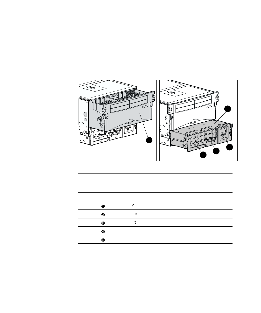
Server Components
In Compaq ProLiant DL760 servers, you can access options and accessories
easily through a sliding top access panel and three removable modules–the
Processor and Memory Module, the media module, and the I/O module. See
Figure 1-1 and Figure 1-2 for identification of these modules and other
components.
2
1
3
5
4
Figure 1-1. Compaq ProLiant DL760 server - front view
Table 1-1
Compaq ProLiant DL760 Server - Front View
Item Component
Processor and Memory Module
Media module
Integrated Management Display (IMD)
IDE CD-ROM drive
1.44 MB diskette drive
Page 19
Server Features 1-3
1
2
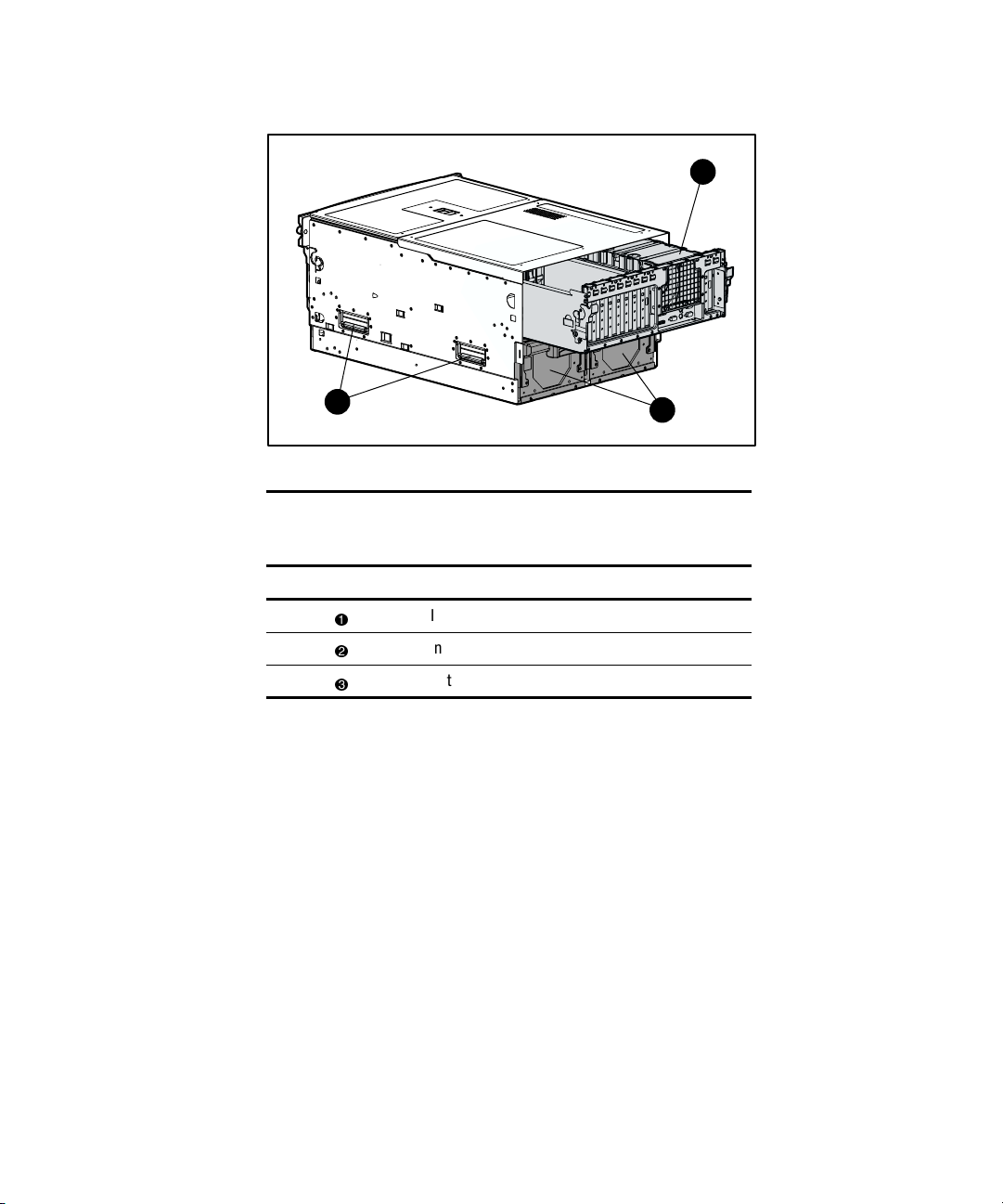
Figure 1-2. Compaq ProLiant DL760 server - rear view
Table 1-2
Compaq ProLiant DL760 Server - Rear View
Item Component
I/O module with system fans
Integrated server lift handles
Hot-plug power supplies
3
Page 20

1-4 Compaq ProLiant DL760 Servers User Guide
New Technology
The Compaq ProLiant DL760 server has several new technology features.
PCI-X Support
PCI-X technology leverages the wide acceptance of the PCI bus and provides
an evolutionary I/O upgrade to conventional PCI. PCI-X technology increases
bus capacity to more than eight times the conventional PCI bus bandwidth —
from 133 MB/s with the 32-bit, 33-MHz PCI bus to 1066 MB/s with the 64bit, 133-MHz PCI-X bus. It enhances the PCI protocol to develop an industrystandard interconnect that exceeds a raw bandwidth of 1 gigabyte per second
(GB/s) and will meet upcoming bandwidth needs of enterprise computing
systems. PCI-X provides backward compatibility with the PCI bus at both the
expansion board and system level.
Compaq ROM-Based Setup Utility Support
The Compaq ROM–Based Setup Utility (RBSU) will automatically configure
the system based on the operating system selected. RBSU supports a wide
range of customizable configuration features. RBSU replaces the System
Configuration Utility feature.
Faster Processor Support
The ProLiant DL760 server offers support for faster Intel Pentium III Xeon
processors. The server is capable of supporting up to eight processors and
eight Processor Power Modules. Each processor requires an associated
Processor Power Module. A ninth Processor Power Module is always present
to provide processor bus termination power.
NOTE: The server will NOT boot if the Intel Pentium III Xeon processors are NOT the same
speed.
Page 21

Standard Features
The following features are available on Compaq ProLiant DL760 server
models.
Processor and Redundant Processor Power Modules
■ Supports up to eight Intel Pentium III Xeon processors
■ Optimal thermal dissipation
G Evaporator plate and water-cooled heat pipes are attached to each
processor
■ Processor Power Modules
G One redundant Processor Power Module per processor
G One Processor board Processor Power Module to power the board
for higher availability
Server Features 1-5
System Memory
■ ECC with single-bit error correction and detection to a single DIMM,
and multibit error detection to the memory bank
■ Supports 100 MHz Registered SDRAM
■ Expandable to 16 GB
■ Supports up to eight memory banks with each bank consisting of two
DIMMs. One bank is installed or removed at a time. Each DIMM of a
given bank must be of the same size, type, and speed.
Cache Accelerator
■ Increases system performance
■ Required for more than four processors or if processors are installed on
both processor buses
Page 22

1-6 Compaq ProLiant DL760 Servers User Guide
Expansion Slots
The server has eleven 64-bit I/O expansion slots that are spread over three
separate buses.
■ The Primary Bus (slots 7-9) will support PCI expansion boards at
33 MHz.
■ The Secondary Bus (slots 1-6) will support PCI expansion boards at
33 MHz or PCI-X expansion boards up to 50 MHz.
■ The Tertiary Bus (slots 10-11) will support PCI expansion boards up to
66 MHz or PCI-X expansion boards up to 100 MHz.
NOTE: Most expansion boards will work in any slot selected, but optimum performance is
obtained when expansion boards are grouped by capability and placed in buses together.
NOTE: Compaq recommends installing 100-MHz PCI-X expansion boards in the Tertiary
Bus, and 66-MHz PCI-X expansion boards in the Secondary Bus.
Network Controller
Supports a dual-port 10/100 TX UTP controller on the PCI local bus. Features
of the controller include two RJ-45 connectors for 10BaseT or 100TX
Ethernet. For information about the network controller, refer to the Compaq
website at
http://www.compaq.com
Redundant Network Controller (NIC) software, located on the Compaq
Support Software CD, supports a redundant NIC configuration. This feature
may be used with one dual-port, two dual-port, or two single-port NICs.
NOTE: When not using the dual-port capabilities, install the terminator plug from the
second RJ-45 connector.
Page 23

PCI Hot Plug
PCI Hot Plug provides the ability to remove, replace, upgrade, and add
PCI/PCI-X expansion boards without powering down the server. Any
PCI/PCI-X board can be placed in a PCI Hot Plug slot. PCI Hot Plug device
drivers and operating system support, however, are required to enable PCI
Hot Plug.
The PCI Hot Plug button allows for PCI Hot Plug access directly at each
PCI/PCI-X slot. A PCI Hot Plug button is located above each PCI/PCI-X slot,
providing PCI Hot Plug control directly at the server without the use of the
PCI Hot Plug utility software.
For more information about PCI Hot Plug, refer to the Server
Documentation CD.
Disk Controller
The Compaq ProLiant DL760 server is provided with a Dual Channel
Integrated Smart Array Controller. One channel is dedicated to the internal
drive bay and the other channel is connected to the external SCSI connector.
See Chapter 8, “Configuring the Server,” for descriptions of the features and
array setup procedures for these controllers
Server Features 1-7
.
Internal Hot-Plug Drive Bays
The internal hot-plug drive bays support four 1-inch, Ultra3 hard drives.
Drives may be of any storage capacity, but must be mounted on Compaq
universal drive carriers (hot-plug drive trays).
Internal drives are controlled by a Dual Channel Integrated Smart Array
Controller. See Chapter 8, “Configuring the Server,” for a description of the
integrated controller.
Fixed Internal Media Drive Bays
The fixed internal media drive bays support two non-hot-plug media drives:
■ 1.44-MB diskette drive
■ IDE CD-ROM drive
Page 24
1-8 Compaq ProLiant DL760 Servers User Guide
Video
The Compaq Integrated PCI Video Controller with 2 MB of RAM provides
maximum resolution of 1024 x 768 non-interlaced resolution. It supports:
■ 16 to more than 256 colors, depending on graphics mode
■ SVGA, VGA, and EGA graphics resolution
Redundant Hot-Plug Power Supplies
■ The Compaq ProLiant DL760 server supports 1150/500W hot-plug
redundant power supplies.
WARNING: Hot-plug power supplies are not designed to be installed with AC
current connected to the power supply. To prevent personal injury or damage to
the equipment, be sure to disconnect the power supply from AC current prior to
its removal or installation.
■ Power supplies are load-balancing and have microcontroller monitoring
for advanced health and configuration management.
■ Supports up to two power supplies. See the Power Requirements section
of Chapter 2, “Installing the Server in a Rack,” to determine power
supply requirements.
Redundant Hot-Plug Fan
ProLiant DL760 servers include a 1+1 redundant hot-plug fan. If the primary
fan fails, the server generates a system alert and triggers the secondary fan to
take over automatically. This redundant hot-plug system fan protects the
various server components from overheating and possible system interruption.
Page 25

Supported Interfaces
Supported interfaces include:
■ Ultra2 SCSI VHDCI connector
■ Serial (two connectors)
■ Video port
■ Parallel port
■ Keyboard connector
■ Mouse connector
Optional Features
The ProLiant DL760 server supports a wide range of server hardware options.
Compaq server options are available from a Compaq authorized reseller or
Compaq authorized service provider. Additional information on Compaq
servers and options can be found at the Compaq website.
This guide also provides basic installation instructions for the following server
options. Hardware options installation instructions can be found inside each
hardware option kit.
■ Redundant hot-plug power supplies
Server Features 1-9
■ Intel Pentium III Xeon processors
■ Redundant Processor Power Modules
■ Cache Accelerator
■ Dual Inline Memory Module (DIMM)
■ Ultra3 Hot-plug hard drives
■ I/O expansion boards (including PCI-X and PCI expansion boards with
PCI Hot Plug driver support)
■ Remote Insight Lights-Out Edition
■ Integrated Array Bypass kit
Page 26

1-10 Compaq ProLiant DL760 Servers User Guide
Server Configuration and Management Features
Compaq offers an extensive set of features and tools to support effective server
configuration and management. Some features are listed below:
■ Compaq SmartStart
■ Compaq ROM-Based Setup Utility
■ Compaq Remote-Flash Redundant ROM
■ Microsoft Windows 2000 Utilities
■ Microsoft Windows NT Utilities
■ Novell NetWare Utilities
■ SCO UnixWare Utilities
■ Compaq Insight Manager/Compaq Insight Manager XE
■ Compaq Integrated Management Log (IML)
■ Compaq Integrated Management Display (IMD)
Compaq SmartStart
SmartStart, which is located on the SmartStart and Support Software CD, is
the intelligent way to configure your Compaq server with Microsoft, Novell,
and SCO system software. SmartStart uses a step-by-step process to configure
the server and to load the system software, thereby achieving a well-integrated
server to ensure maximum dependability and supportability.
For information about SmartStart, refer to the Server Setup and Management
pack included in the shipping box.
Page 27

Compaq ROM-Based Setup Utility
d
The Compaq ROM-Based Setup Utility (RBSU) automatically configures the
system based on the selected operating system. It supports a wide range of
configuration customization features, including the following:
■ Selection of a primary operating system from a list of supported
operating systems
■ Selection of a Primary Boot Controller from a list of installed mass
storage devices
■ Configuration of embedded system devices such as serial and mouse
ports
■ Configuration of standard interrupts (IRQs) for PCI devices
■ Setting of date and time
■ Configuration of Integrated Management Display (IMD) and system
asset text
■ Automatic resolution of resource conflicts in areas such as port
addresses and interrupts (IRQs)
■ Storage of configuration in nonvolatile memory
Server Features 1-11
The RBSU is preinstalled in the embedded system ROM on the server. The
RBSU has embedded support for English, French, German, Italian, Spanish,
and Japanese languages.
NOTE: Systems that use RBSU do not support the System Configuration Utility. For
additional information on using ROM-Based Setup Utility, refer to the Compaq ROM-Base
Setup Utility User Guide located on the Documentation CD.
Page 28

1-12 Compaq ProLiant DL760 Servers User Guide
Compaq Remote-Flash Redundant ROM
This server is equipped with a Remote-Flash Redundant ROM that gives the
system the ability to recover the last known good system ROM in the event
that the current system ROM has been corrupted. When the server leaves the
factory, both system ROMs contain the same image.
Microsoft Windows 2000 Utilities
Compaq servers running Windows 2000 take advantage of several utilities that
provide detailed system information and offer the following special
capabilities:
■ Compaq Array Configuration Utility
■ Compaq Power Down Manager
■ Compaq Power Supply Viewer
■ Compaq Integrated Management Log Viewer
■ Compaq Integrated Management Display Utility
These utilities are provided on the Compaq Support Paq for Microsoft
Windows 2000.
Page 29

Microsoft Windows NT Utilities
Compaq servers running Windows NT 4.0 take advantage of several utilities
that provide detailed system information and offer the following special
capabilities:
■ Compaq Array Configuration Utility
■ Compaq Advanced Network Control Utility
■ Compaq Fibre Fault Isolation Utility
■ Compaq Cluster Verification Utility
■ Compaq PCI Hot Plug Utility
■ Compaq Power Down Manager
■ Compaq Power Supply Viewer
■ Compaq Integrated Management Log Viewer
■ Compaq Integrated Management Display Utility
These utilities are provided as a part of the Compaq Support Paq (CSP) for
Microsoft Windows NT 4.0. For information, refer to the NTREADME.HLP
file included in the CSP.
Server Features 1-13
Novell NetWare Utilities
Compaq servers running Novell NetWare can take advantage of the following
utilities:
■ Compaq Power Supply Viewer (with Power Down Manager)
■ Compaq Integrated Management Log Viewer (with IMD Online
Configuration)
This utility is provided as part of the Compaq Support Paq for Novell
NetWare.
Page 30

1-14 Compaq ProLiant DL760 Servers User Guide
SCO UnixWare Utilities
Compaq servers running SCO UnixWare take advantage of the C22SSD
Utility.
This utility is provided as part of the Compaq Extended Feature Supplement
(EFS) for SCO UnixWare. The EFS is available on the SmartStart and Support
Software CD.
Compaq Insight Manager/Insight Manager XE
Compaq Insight Manager is a systems management tool delivering
performance, configuration, and fault management for Compaq servers and
clients. Compaq Insight Manager has two components:
■ Compaq Insight Manager software, which runs on the management
console
■ Compaq Management Agents (operating system-specific), which run on
the server or managed desktop client
Compaq Insight Manager features an easy-to-use graphical interface and
includes online documentation and context-sensitive help. Key features
include:
■ Server fault condition alerts
■ Server performance and fault condition monitoring
■ Server security and configuration control
■ Remote control of the server
■ Rapid recovery services
For information concerning Compaq Insight Manager, refer to the Server
Setup and Management pack shipped with your server.
Page 31

Compaq Web-Enabled Server Management
Compaq Web-Enabled Server Management allows you to access your
managed Device List and the Compaq Insight Manager Alarm Log with a Web
browser, either locally at the management console or from another machine. If
you have devices that are running Compaq Insight Management Agents v5.x,
you can also view the device data using a Web browser.
Starting with the web release, two buttons have been added to the button bar in
Compaq Insight Manager. One button launches your browser with the Device
List displayed, the other button launches your browser with the Alarm Log
displayed.
For web-enabled devices (devices that are running Compaq Insight
Management Agents v5.x), a task will also appear in the Task List for viewing
web data.
Compaq Integrated Management Log
The Compaq Integrated Management Log (IML) records all system events and
stores them in an easily viewable form. These events are recorded and marked
with a time stamp. For more information about the IML, see Chapter 9,
“Integrated Management Log.”
Server Features 1-15
Compaq Integrated Management Display
The Integrated Management Display (IMD) is a server management tool
delivering fault information, service, and configuration capabilities in an easy-
to-use, integrated hardware display. IMD features include:
■ POST messages
■ User-defined administrative information
■ Configuration information
■ System alerts and event descriptions
For information about the IMD, see Chapter 9, “Integrated Management Log.”
Page 32

1-16 Compaq ProLiant DL760 Servers User Guide
Diagnostic Tools
Some of the software, firmware, and hardware diagnostic features of the
Compaq ProLiant DL760 server include:
■ All diagnostic LEDs viewable from the exterior
■ Power-On Self-Test (POST)
■ Diagnostics (DIAGS)
■ ROMPaq™ utilities to upgrade flash ROMs
■ Array Configuration Utility (ACU)
■ Integrated Management Display (IMD)
■ Integrated Management Log (IML)
For information about Compaq diagnostic tools, refer to either the
Compaq Servers Troubleshooting Guide on the Server Documentation CD or
Appendix E, “Troubleshooting Information.”
Page 33

Security Features
For detailed information about security features, refer to the Server
Documentation CD.
Software Security
The following software security features are established through the Compaq
ROM-Based System Utility:
■ Administrator password—prevents changes to the configuration unless
you enter the password.
■ Diskette drive control—enables and disables the diskette drive. When
disabled, the diskette drive will not read, write, or boot.
■ Diskette write control—enables and disables diskette write functions.
When disabled, will not write, but boot and read functions are still
available.
■ Power-on password—locks out the keyboard preventing unauthorized
access to Compaq servers. The keyboard lock out prevents logins or
commands until the proper password is entered.
Server Features 1-17
■ Network server mode—permits system startups from a hard disk or
network server while the keyboard and mouse are disabled.
■ QuickLock—disables the keyboard and mouse without exiting the
application. The application remains in view on the monitor screen, but
cannot be accessed.
■ Serial interface control—disables the serial port. When disabled, all data
transfer through the integrated serial port is blocked.
Hardware Security
The following hardware security features are established by a switch on the
I/O board:
■ Configuration (NVRAM) lock—disallows configuration changes when
in use by not allowing nonvolatile memory to be modified.
■ Diskette Boot Control—enables and disables the diskette boot functions.
When disabled, the system will not boot from a diskette, but runtime
diskette read and write functions are still available
Page 34

1-18 Compaq ProLiant DL760 Servers User Guide
Routine Maintenance
For information about routine maintenance and safety precautions, refer to the
Server Documentation CD included in the Reference Information pack of the
shipping box.
Warranty
■ Three-Year Parts, Labor, and On-Site Limited Warranty with next
business day response
■ Pre-Failure Warranty on processors, memory, and hard drives (requires
installation of Compaq Insight Manager
■ For additional service and support offerings, visit the Compaq website at
http://www.compaq.com
)
Page 35

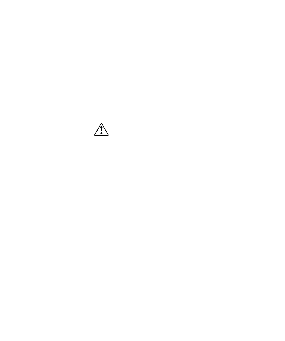
Chapter 2
Installing the Server in a Rack
This chapter specifies the procedures required to install a ProLiant DL760
server in a Compaq or industry-standard 19-inch rack.
Figure 2-1. Compaq ProLiant DL760 Server
Page 36

2-2 Compaq ProLiant DL760 Servers User Guide
Rack Installation Overview
Installing the ProLiant DL760 server in the rack requires the following steps
(detailed later in this chapter):
1. Select a site and unpack the server. See the next sections, “Selecting a
Site” and “Shipping Box Contents” in this chapter.
2. Remove the power supply, I/O Module, and Processor and Memory
Module shipping brackets. Refer to “Removing the Shipping
Safeguards” later in this chapter.
3. Release the top access panel latch. Slide the top access panel open and
loosen the shipping screw on top of the unit.
4. Loosen the shipping screw between the I/O Module and the
Processor and Memory module. See “Removing the Shipping
Safeguards” later in this chapter.
5. Install any expansion boards or other options, such as additional
memory. Refer to Chapter 4, “Installing Hardware Options – Server
Power Off,” and Chapter 5, “Installing Hardware Options – Hot
Pluggable,” for more information on hardware options and expansion
boards.
Run the ROM-Based Setup Utility after you install certain hardware
options, with the exception of additional memory and most PCI/PCI-X
boards.
NOTE: Refer to the Server Setup and Management pack shipped with your server to run
the ROM-Based Setup Utility. See Chapter 4, “Installing Hardware Options–Server Power
Off,” and Chapter 5, “Installing Hardware Options–Hot Pluggable,” to install many of the
major options.
NOTE: If the operating system is pre-installed on the server, refer to the Compaq Factory
Installed Operating System Software User Guide that is included with the server.
6. Remove the Processor and Memory module, Media Module, and
power supplies to lighten the chassis.
7. Install the chassis in the rack and replace the modules and power
supplies.
8. Connect the cables: keyboard, mouse, monitor, network, storage,
and power. See Chapter 6, “Cabling the Server.”
Page 37

Selecting a Site
When installing your ProLiant DL760 server in a rack, the following standards
must be met:
■ Space requirements
■ Power requirements
■ Grounding requirements
■ Temperature requirements
■ Airflow requirements
Space Requirements
Consider the following items when deciding where to install your Compaq
rack:
■ Clearance in the front of the rack should be a minimum of 25 inches for
servicing.
■ Clearance in the back of the rack should be a minimum of 30 inches to
allow for servicing and for adequate airflow.
Installing the Server in a Rack 2-3
Page 38

2-4 Compaq ProLiant DL760 Servers User Guide
Power Requirements
WARNING: To reduce the risk of personal injury, fire, or damage to the
equipment, do not overload the AC supply branch circuit that provides power to
the rack. Consult the electrical authority having jurisdiction over your facility
wiring and installation requirements
IMPORTANT: Because of the 100 to 240 VAC electrical rating of each power supply,
some local electrical authorities may require either one 15-Ampere circuit for each power
supply or one 20-Ampere circuit for both power supplies.
■ The power load needs to be balanced between available AC supply
branch circuits.
■ The overall system AC current load must not exceed 80 percent of the
branch circuit AC current rating.
■ If a power strip is used, the load should not exceed 80 percent of the
power strip’s marked electrical current rating.
NOTE: For server specifications, refer to Appendix F, “Server Specifications.”
The installation of this equipment shall be in accordance with local or regional
electrical regulations governing the installation of Information Technology
Equipment by licensed electricians. This equipment is designed to operate in
installations covered by the National Electric Code (ANSI/NFPA 70, 1999)
and the code for Protection of Electronic Computer/Data Processing
Equipment (ANSI/NFPA 75, 1992).
For electrical power ratings on options, refer to the product’s rating label or
user documentation supplied with that option.
IMPORTANT: There is a limited maximum configuration if using 110V input line voltage
on the ProLiant DL760 server. See Table 2-1 for more information on power supply
parameters.
Page 39

Installing the Server in a Rack 2-5
Power Supplies
■ The ProLiant DL760 server has two hot-plug, redundant power supplies.
Depending upon the system load configuration, more than one power
supply may be required to power the system. See Table 2-1 to determine
power supply requirements.
■ Power supplies are load-balancing and have microcontroller monitoring
for advanced health and configuration management.
Refer to Table 2-1 to determine the number of power supplies needed for the
server.
Table 2-1
Redundant Power Supply Operation
Input Power
Line Type
110 VAC 4 1 to 4 2 GB to 16 GB 1 to 5
240 VAC 8 1 to 4 2 GB to 32 GB 1 to 11
Note: This table assumes worst-case power loading from all components simultaneously
for worst-case temperature and input power conditions. Actual performance may vary
depending on server application.
■ To estimate the power requirements for a specific server configuration,
Processors Hard Drives Memory PCI Expansion
Boards
use the Power Calculation Utility located on the Compaq
ActiveAnswers™ Online Solutions website:
http://activeanswers.compaq.com
1. Select System Configurator under Tools.
2. Click on Select Product Family and then choose ProLiant Servers.
3. Select the ProLiant DL760 server.
The next web pages contain information and a link to the Power
Calculator.
Page 40

2-6 Compaq ProLiant DL760 Servers User Guide
Power supply advanced features include:
■ Auto Line Sensing capability. No switch is needed to select the
appropriate line voltage.
■ Power Supply Viewer Utility under Microsoft Windows NT and
Windows 2000
■ Power Down Manager Utility under Microsoft Windows NT and
Windows 2000
■ Power Supply Utility under NetWare
The utilities developed for Windows NT are provided as part of the Compaq
Support Paq (CSP) for Microsoft Windows NT 4.0. For more information,
refer to the NTREADME.HLP file included in the CSP. The utility developed
for NetWare is provided as part of the Compaq Support Paq for Novell
NetWare.
NOTE: Power supplies provide 1150 Watts of power to the system from 240 VAC input
line voltage, and 500 Watts of power from 110 VAC input line voltage.
Page 41

Installing the Server in a Rack 2-7
System Power Management Guidelines
The following guidelines are provided to assist you in calculating power
usage.
NOTE: The following guidelines are general. Use the Compaq Power Subsystem Utility
and option documentation to obtain the most accurate power capacity and of power
margin assessment.
To estimate the power requirements for a specific server configuration, use the
Power Calculation Utility located on the Compaq ActiveAnswers Online
Solutions website:
http://activeanswers.compaq.com
1. Select System Configurator under Tools.
2. Click on Select Product Family and then choose ProLiant Servers.
3. Select the ProLiant DL760 server.
The next web pages contain information and a link to the Power
Calculator.
Unless you are operating with two 1150W power supplies at 220V, it may be
necessary to make tradeoffs with respect to which options can be added and
powered with the installed power supplies. Use the following guidelines when
evaluating these tradeoffs:
■ Comparing processor and hard drive power–two processors draw as
much current as the four hard drives.
■ Comparing memory and 3.3V-powered PCI/PCI-X Expansion Board
power–each additional 512 MB draws approximately as much current as
one to two PCI/PCI-X boards.
A single 3.3V PCI/PCI-X expansion board draws 25W.
■ Comparing hard drive and 5V-powered PCI Expansion Board Power–
one PCI expansion board draws as much current as two to five hard
drives.
Page 42

2-8 Compaq ProLiant DL760 Servers User Guide
Grounding Requirements
WARNING: To reduce the risk of electrical shock due to high leakage currents,
a reliable grounded connection (earthed) is essential before connecting the unit
to an AC supply.
For proper operation and safety, this equipment is required to be properly
grounded. In the United States, install the equipment in accordance with
ANSI/NFPA 70, 1999, Article 250, as well as any local and regional building
codes. In Canada, the equipment should be installed in accordance with
Canadian Standards Association, CSA C22.1, Canadian Electrical Code. In all
other countries the installation should follow any regional or national electrical
wiring codes, such as the International Electrotechnical Commission (IEC)
364, parts one through seven. All power distribution devices used in the
installation, including branch wiring, receptacles, and so on, should be Listed
or Certified ground-type devices.
Due to the higher ground leakage currents associated with the equipment,
Compaq recommends the use of a Power Distribution Unit (PDU) that
provides a supplementary ground conductor. This supplementary ground
conductor should be permanently connected to a suitable building ground
terminal. The use of common power outlet strips for this equipment is not
recommended.
NOTE: For further information on grounding methods in the workplace, see Appendix B,
“Electrostatic Discharge.”
Page 43

Temperature Requirements
To ensure continued safe and reliable operation of the equipment, install the
system in a well-ventilated, climate-controlled environment.
The Compaq Maximum Recommended Ambient Operating Temperature
(TMRA) for most server products is 95°F (35°C). The temperature in the room
where the rack is located should not exceed 95°F (35°C).
The operating temperature inside the rack will always be higher than the room
temperature, and is dependent on the configuration of equipment in your rack.
The TMRA for each piece of equipment should be checked before installation.
The maximum internal rack temperature for your configuration should not
exceed the values shown in Table 2-2.
Rack Internal Temperature Maximums
Equipment Included Maximum Internal Rack Temperature
Rack-Mountable
ProLiant DL760 Servers
Compaq Rack-Mountable options 104°F/40°C
Other manufacturers’ options See other manufacturers’ specifications
Installing the Server in a Rack 2-9
Table 2-2
122°F/43°C
CAUTION: To reduce the risk of damage to the equipment when installing thirdparty options:
■ Ensure that the optional equipment does not impede airflow to the Rack-
Mountable ProLiant DL760 servers or increase the internal rack
temperature beyond the Compaq specified maximum rating.
■ Ensure that the Manufacturer’s Maximum Recommended Ambient
Operating Temperature of the optional equipment is not exceeded when
installed in the rack.
Page 44

2-10 Compaq ProLiant DL760 Servers User Guide
Airflow Requirements
The Compaq ProLiant DL760 server draws cool air in through the front door
and exhausts warm air out through the rear door. Therefore, the front door of
the rack must be adequately ventilated to allow ambient room air to enter the
cabinet, and the rear door must be ventilated adequately to allow the warm air
to escape from the cabinet. Do not block the ventilation apertures.
CAUTION: If a third-party rack is used, the following minimum requirements
should be observed to ensure adequate airflow and to prevent damage to the
equipment:
■ Front: The rack door should have 120 square inches of holes evenly
distributed from top to bottom to permit adequate air flow.
■ Side: The clearance between the installed module and the side panels of
the rack should be a minimum of 2.75 inches.
■ Rear: The clearance between the back of the rack and the wall should be a
minimum of 30 inches, and the equipment should be operating without a
rear door.
CAUTION: If all of the vertical space in the rack is not filled by components, the
gaps left will cause a change in airflow through the rack and across the
components. These gaps need to be covered with blanking rack panels.
High Airflow Rack Door Insert
The increased power of new processor technology requires increased cooling
efficiency for rack-mounted servers. The new Compaq Rack 9000 series
provides enhanced airflow for maximum cooling, allowing these racks to be
fully loaded with servers using the latest processors.
When installing this server in Compaq Rack 7000 and 4000 series, the new
processor technology requires the installation of a new Compaq High Airflow
Rack Door Insert, if the rack has a LEXAN front door.
Page 45

Shipping Box Contents
Unpack the shipping boxes by following the instructions and illustrations
printed on the outside of the boxes. Locate the following materials:
■ ProLiant DL760 server
■ Power cords (located inside country kit box with documentation pack)
■ Documentation inside the server (Most of the option installation and
setup instructions are located on hood labels on top of the unit and on
the sides of the Processor and Memory module.)
■ Hardware documentation and software packs (inside the country kit
box), including Server Setup and Management, Reference Information,
and Software Products
In addition to these supplied items, you may need the following unsupplied
items to complete the installation:
■ T-15 Torx screwdriver
■ Options to be installed such as expansion boards, monitors,
uninterruptible power supply (UPS), power supplies, hard drives,
hard-drive cages, tape drives, processors and their power modules, or
additional memory
Installing the Server in a Rack 2-11
■ Application software
■ Cage nut fitting tool
■ Phillips-head and flat-head screwdrivers
■ Pencil
Page 46

2-12 Compaq ProLiant DL760 Servers User Guide
Removing the Shipping Safeguards
To protect the power supply, Processor and Memory Module, and I/O module
from any damage during shipment, each is installed with a protective covering
bracket.
1. Loosen the screws and remove the power supply bracket as shown in
Figure 2-2 and Figure 2-3.
IMPORTANT: Save the bracket in a safe location. You will need to replace it if you have
to ship the server in the future.
2. After loosening the retaining screw
, rotate the bracket away from the
server by pulling on the right end of the bracket
3. When the left end disengages, remove the bracket
1
3
Figure 2-2. Removing the power supply shipping bracket
2
.
.
Page 47

Installing the Server in a Rack 2-13
4. Remove the I/O shipping bracket by loosening the retaining screws
and lifting the bracket up and out .
2
1
Figure 2-3. Removing the I/O shipping bracket
The ProLiant DL760 server has a top latch security screw, as shown in Figure
2-4. The screw prevents access to the Processor and Memory Module and the
I/O module.
5. Unlock the top latch security screw
Slide the top access panel toward the front of the server
and then pull the latch forward .
.
2
Figure 2-4. Opening the top access panel
1
3
3
Page 48

2-14 Compaq ProLiant DL760 Servers User Guide
6. Open the air baffle
.
7. Loosen the shipping screw between the Processor and Memory Module
and the I/O module as shown in Figure 2-5
1
Figure 2-5. Loosening the shipping screw
Install any Expansion Boards or Optional Features
.
2
The installation of any I/O expansion boards or other hardware options, such
as additional memory, can be done before mounting the server in the rack.
Refer to Chapter 4, “Installing Hardware Options – Server Power Off,” and
Chapter 5, “Installing Hardware Options – Hot Pluggable,” for more
information on installing hardware options and expansion boards.
Run the ROM-Based Setup Utility after you install certain hardware options,
with the exception of additional memory and most PCI/PCI-X boards.
NOTE: Refer to the Server Setup and Management pack shipped with your server to run
the ROM-Based Setup Utility. See Chapter 4, “Installing Hardware Options–Server Power
Off,” and Chapter 5, “Installing Hardware Options–Hot Pluggable,” to install many of the
major options.
NOTE: If the operating system is pre-installed on the server, refer to the Compaq Factory
Installed Operating System Software User Guide that is included with the server.
Page 49

Rack Warnings and Precautions
Before beginning these procedures, make sure you understand the following
warnings:
WARNING: To reduce the risk of personal injury or damage to the
equipment:
42 - 62 kg
93 - 137 lb
WARNING: To reduce the risk of personal injury or damage to the equipment,
be sure that:
■ The leveling jacks are extended to the floor.
■ The full weight of the rack rests on the leveling jacks.
■ The stabilizing feet are attached to the rack if it is a single rack installation.
■ Observe local occupational health and safety requirements and
guidelines for manual material handling.
■ Obtain adequate assistance to lift and stabilize the chassis
during installation or removal. The product will be unstable
when not fastened to the rails.
■ Remove all hot-plug power supplies and drives to reduce the
overall weight of the product.
Installing the Server in a Rack 2-15
■ The racks are coupled together in multiple rack installations.
■ Only one component is extended at a time. A rack may become unstable if
more than one component is extended for any reason.
IMPORTANT: To reduce the overall weight of the system, Compaq recommends that all
power supplies, hot-plug hard drives, and top access panel be removed from the server
before loading it onto the rails.
IMPORTANT: Refer to the following rack documentation for further cautions:
■ 9000 Rack Series Products Audio-Visual (AV) CD Kit (shipped with Compaq racks)*
■ Rack Builder Pro Configuration Tool CD (available on the Compaq website or can be
ordered with the Rack Resource CD Kit)
■ Rack Products Documentation CD (available on the Compaq website or can be
ordered with the Rack Resource CD Kit)
* The Rack 7000/4000 Series Rack Resource CD Kit ships with all Compaq 7000 and
4000 Series Racks.
Page 50

2-16 Compaq ProLiant DL760 Servers User Guide
Server Warnings and Precautions
WARNING: To reduce the risk of electric shock or damage to the equipment:
■ Do not disable the power cord grounding plug. The grounding plug is an
important safety feature.
■ Plug the power cord into a grounded electrical outlet that is easily
accessible at all times.
■ Install the power supply before connecting the power cord to the power
supply.
■ Unplug the power cord before removing the power supply from the server.
■ If the system has multiple power supplies, disconnect power from the
system by unplugging all power cords from the power supplies.
CAUTION: Because the ProLiant DL760 server does not have safety interlocks,
it is possible for a unit to be operated without the cover and air baffles properly
installed. This could cause thermal damage in the system and may void your
warranty. The Rack-Mountable Compaq ProLiant Server should always be
operated with the system unit cover on. Proper cooling will not be achieved if
the system unit cover is left open for a long period of time.
Page 51

Installing the Server in a Rack
Lightening the Chassis
Using the following steps, remove the modules from the chassis to lighten the
server:
1. Remove the Processor and Memory Module and Media module from the
server.
Installing the Server in a Rack 2-17
Figure 2-6. Removing the front modules from the server
2. Remove the power supplies.
3
2
Figure 2-7. Removing the power supplies
1
1
2
Page 52

2-18 Compaq ProLiant DL760 Servers User Guide
Attaching the Inner Slide Rails to the Server
Carefully align the three screw holes on each side of the server and the slide
rail assembly. Attach the server to the inner slide with six 8-32 x 1/4-inch
slotted head screws.
Figure 2-8. Attaching the inner slide rails to the server
Page 53

Attaching the Outer Slide Rail Assembly to the Rack
Attaching the slide rail assembly to the rack consists of the following steps:
■ Marking the server’s rack position with the template
■ Inserting the cage nuts into the rack frame
■ Installing the outer slide rail assembly into the rack
Marking the Rack with the Template
Use the template provided with the kit to mark the rack for cage nut and
mounting bracket positions. Starting at the bottom of the rack or at the top of a
previously mounted component.
1. Place the template in the desired location on the front of the rack and
secure it in place with the rail covers. Make sure that you match the hole
pattern printed on the template with the actual holes on the rack’s
vertical rails. Tap the rail covers sharply to snap the template into place.
Installing the Server in a Rack 2-19
Figure 2-9. Applying the template to the rack
Page 54

2-20 Compaq ProLiant DL760 Servers User Guide
2. Use a pencil to mark the top two locations indicated on the template for
the cage nuts that will hold the captive thumbscrews on the rack mount
front panel.
3. Remove the template from the rack by grasping the middle of the top
and bottom edges and gently pulling the template as shown in
Figure 2-10. This should allow the template to pull away from the
plastic rail covers leaving the rail covers in place.
Figure 2-10. Removing the template from the rack
Page 55

Installing the Server in a Rack 2-21
Inserting Cage Nuts into the Rack Frame
The cage nuts fit inside the rails at the marked locations.
1. Use the cage nut fitting tool to insert a cage nut into the rails. Squeeze
the prongs together
the rack
.
and insert the cage nut into the appropriate hole in
1
2
1
Figure 2-11. Inserting cage nuts
2. Repeat step 1 for all of the cage nuts on the front and the back rails of
the rack. Also mark where the top of the template is on the rack. This
helps align the components to be installed next.
Page 56

2-22 Compaq ProLiant DL760 Servers User Guide
Installing the Outer Slide Rail Assembly into the Rack
To install the outer slide rail assembly:
1. Place a mounting bracket in position according to the pencil marks made
earlier.
2. Attach the front of the bracket on the inside of the front of the rack
with one M6 x 1.0-12L Phillips screw in the bottom hole as shown
in Figure 2-12. Do not use washers.
IMPORTANT: Use one screw only in the bottom hole of the bracket; otherwise, proper
alignment is impossible.
Figure 2-12. Attaching slide rail assembly to the front of the rack
Page 57

Installing the Server in a Rack 2-23
3. Secure the back of each mounting bracket on the outside of the back of
the rack with one cage nut and one M6 x 1.0-12L Phillips screw in the
bottom hole of the bracket as shown in Figure 2-13.
IMPORTANT: Make sure that the mounting bracket is level from front to back. Use one
screw only in the bottom hole of the bracket; otherwise, proper alignment is impossible.
Figure 2-13. Attaching the slide rail assembly to the back of the rack
Page 58

2-24 Compaq ProLiant DL760 Servers User Guide
Sliding the Server into the Rack
WARNING: To reduce the risk of personal injury or damage to the equipment:
■ Observe local Occupational Safety requirements and guidelines for heavy
equipment handling.
■ Obtain adequate assistance to lift and stabilize the chassis during
installation or removal.
■ Remove all pluggable power supplies and modules to reduce the weight of
the chassis.
■ Use caution—the unit will be unstable when not mated with the rails.
IMPORTANT: To reduce the weight of the system, Compaq recommends that all power
supplies, the Processor and Memory Module, and the Media module be removed from the
system before loading it onto the rails.
1. Fully extend the outer slide rails forward until snapped in the locked
position
.
1
2
Figure 2-14. Extending the slides
2. Lift the server with the recessed Integrated Server Lift Handles
3. Insert the inner slide rails on the server into the extended outer slide rails
mounted on the rack.
.
Page 59

Installing the Server in a Rack 2-25
4. Depress the slide safety tabs to push the server into the rack
.
5. Slide the server between the extended slides into the rack as far as the
server will go
.
2
1
Figure 2-15. Setting the server on the slide rails
WARNING: To reduce the risk of personal injury, be careful when pressing the
component rail release latches and sliding the component into the rack. The
slide rails could pinch your fingertips.
CAUTION: Be sure to keep the server parallel to the floor when sliding the
component rails into the slide rails. Tilting the component up or down could
result in damage to the rails.
IMPORTANT: The first time you slide the component into the rack, you may have to apply
some pressure. After the first time, the ball bearings in the slide will move easily.
Page 60

2-26 Compaq ProLiant DL760 Servers User Guide
6. Replace any hardware that was removed for installation (power supplies,
Processor and Memory Module, and Media module).
7. Secure the server to the rack with thumbscrews.
Figure 2-16. Securing the server in the rack with thumbscrews
Page 61

Attaching the Cable Management Assembly
The cable management bracket and arm assembly organizes and secures the
cables in the back of the server. The cable management arm attaches to the
cable management arm bracket on the server and to the rack. All cables to and
from the server are tied to this arm and swing out of the way when you access
the server.
Installing the Cable Management Arm Bracket
The cable management arm bracket holds the cable management arm on the
server.
To install the cable management arm bracket:
1. Slide the server out or access it from the rear of the rack.
2. Attach the cable management arm bracket to the left side of the back of
the server
using the integrated thumbscrew .
Installing the Server in a Rack 2-27
1
2
Figure 2-17. Attaching a cable management arm bracket
Page 62

2-28 Compaq ProLiant DL760 Servers User Guide
Installing the Cable Management Arm
To install the cable management arm into the rack:
NOTE: The following procedure describes installing the cable management arm supplied
with the ProLiant DL760 server. For complex rack installations including a large number
of cables, you can obtain a high capacity cable management arm as an option kit, part
number 124711-B21.
1. Slide the server into the rack.
2. Attach the cable management arm to the cable management arm bracket
using two M6 x 1.0-12L Phillips screws.
Figure 2-18. Attaching the cable management arm to its bracket
Page 63

Installing the Server in a Rack 2-29
3. Align the other end of the cable management arm on the outside of the
rear rack frame. Attach the end with the M6 x 1.0-12L washer face
Phillips-head screws.
Figure 2-19. Attaching the cable management arm to the rack
Page 64

Chapter 3
Server Access
The ProLiant DL760 server provides easy access to all internal components
for installation and maintenance. The information in this chapter provides
details concerning system power and power supply indicators and removal of
the server modules.
Page 65

3-2 Compaq ProLiant DL760 Servers User Guide
Server Access Panel and Modules
The Compaq ProLiant DL760 server chassis facilitates the installation of
hardware upgrades through the use of three removable modules and a sliding
top access panel. Table 3-1 describes the contents of the modules and how to
access the components.
1
Figure 3-1. ProLiant DL760 server modules
2
3
Table 3-1
Module Components and Access
Module Contents To Access
I/O
module
Processor
and
Memory
Module
Media
module
PCI Hot Plug expansion
slots
Configuration switches Slide top access panel toward the front of the server.
Fans 1 and 2 Slide top access panel toward the front of the server.
Processor sockets Remove Processor and Memory Module.
Processor bus/core
ratio switches
Cache Accelerator Remove Processor and Memory Module.
Memory (DIMMs) Open Processor and Memory Module. Remove memory board.
CD-ROM/Diskette/IMD
Hot-plug hard drives Access directly at front of server.
Slide top access panel toward the front of the server. Lift up the
air baffle.
Remove Processor and Memory Module.
Remove Media module.
Page 66

The following sections provide instructions for removing the I/O module,
Processor and Memory Module, and Media module. For information
pertaining to PCI Hot Plug and hot-plug fan access, see Chapter 5, “Installing
Hardware Options - Hot Pluggable.”
CAUTION: Do not attempt to open any of the three modules while power is
applied to the system. They are not hot-pluggable. Immediate system shutdown
and loss of data will occur.
Accessing the I/O Module
To open the I/O module to install or replace hot-plug fans or hot-plug PCI
boards:
1. Slide the chassis out of the rack.
2. Lift the forward-most edges of the top access panel, as indicated by the
arrows in Figure 3-2, and slide it toward the front of the server.
Server Access 3-3
Figure 3-2. Opening the top access panel
3. At this point, you can remove and replace the hot-plug fans and hot-plug
PCI boards as described in Chapter 5, “Installing Hardware Options Hot Pluggable.”
Page 67

3-4 Compaq ProLiant DL760 Servers User Guide
Removing the I/O Module
CAUTION: Do not attempt to open any of the three modules while power is
applied to the system. They are not hot-pluggable. Immediate system shutdown
and loss of data will occur.
NOTE: Use the procedure in the preceding section, “Accessing the I/O Module,” to install
or replace hot-plug fans or hot-plug PCI boards.
To replace or service non-hot-plug components or problems in the I/O module,
remove the module from the chassis:
1. If the computer is on, place the computer in Standby mode and
disconnect the power cord or cords. See Chapter 7, “Server Power.”
2. If replacing an item, it may be necessary to remove all of the cables
connected to the I/O expansion boards.
3. Loosen the cable management arm with the thumbscrew attached to the
cable management arm bracket (as shown in Figure 3-3)
cable management arm to disconnect it
way. The cable management arm is not shown in the figure for clarity.
, and lift the
. Rotate the arm out of the
2
1
Figure 3-3. Disconnecting the cable management arm
4. Push in on the sides of the cam levers on the I/O module
the top of the levers downward
, as shown in Figure 3-4.
and rotate
5. Pull the I/O Module out of the chassis until it reaches the module stop
.
latch
Page 68

Figure 3-4. Releasing the I/O module
Server Access 3-5
3
1
2
6. Press in the module stop latches
chassis
Figure 3-5. Removing the I/O module from the chassis
, as shown in Figure 3-5.
4
and pull the module out of the
5
7. Set the module aside for servicing non-hot-plug components.
WARNING: To reduce the risk of personal injury from hot surfaces, allow the
internal system components to cool before touching them.
8. To view the top panel labels, pull the chassis out of the rack until it
makes contact with the rail stop.
Page 69

3-6 Compaq ProLiant DL760 Servers User Guide
NOTE: These top panel labels provide instructions on installing expansion boards, setting
switches, and installing hot-plug fans, as well as information on PCI Hot Plug. See
Chapter 5, “Installing Hardware Options - Hot Pluggable,” for hot-plug procedures.
9. To reassemble the server, slide the module in until the ejectors begin to
rotate. Then push the ejectors shut until they snap into place.
Page 70

Removing the Processor and Memory Module
WARNING: To reduce the risk of personal injury or damage to the
equipment:
42 - 62 kg
93 - 137 lb
CAUTION: Do not attempt to open any of the three modules while power is
applied to the system. They are not hot-pluggable. Immediate system shutdown
and data loss will occur.
To open the Processor and Memory Module:
1. If the computer is on, place the computer in Standby mode and
disconnect the power cord or cords. See Chapter 7, “Server Power.”
■ Observe local occupational health and safety requirements and
guidelines for manual material handling.
■ Obtain adequate assistance to lift and stabilize the chassis
during installation or removal.
■ Use caution—the product will be unstable when not fastened
to the rails.
■ Remove all hot-plug power supplies and drives to reduce the
overall weight of the product.
Server Access 3-7
2. Push in the sides of the latches on the Processor and Memory Module
and rotate the top of the levers downward , as shown in Figure 3-6.
3. Pull the Processor and Memory Module out of the chassis until it
encounters the module stop latch
Figure 3-6. Opening the Processor and Memory Module
.
3
1
2
Page 71

3-8 Compaq ProLiant DL760 Servers User Guide
4. At this point you can remove the memory board to add or replace
memory modules as described in Chapter 4, “Installing Hardware
Options – Server Power Off.”
5. Press the module stop latches in
chassis
Figure 3-7. Removing the Processor and Memory Module
, as shown in Figure 3-7.
4
WARNING: To reduce the risk of personal injury from hot surfaces, allow the
internal system components to cool before touching them.
and pull the module out of the
5
6. To reassemble the server, slide the module in until the ejectors begin to
rotate. Then push the ejectors shut until they snap into place.
7. Reconnect the cable management arm and any I/O cables if removed.
Processor Serial Number
The Processor Serial Number feature is a Pentium III Xeon processor
manageability feature. It can be used for network inventory and tracking
purposes. Compaq ProLiant DL760 servers are shipped with this feature
disabled. You can enable the feature using the ROM-Based Setup Utility.
Page 72

Removing the Media Module
CAUTION: Do not attempt to open any of the three modules while power is
applied to the system. They are not hot-pluggable. Immediate system shutdown
and data loss will occur.
To remove the media module:
1. If the server is on, place it in Standby mode and disconnect the power
cord or cords. See Chapter 7, “Server Power.”
Server Access 3-9
2. Push in the sides of the cam levers on the media module
the top of the levers downward
, as shown in Figure 3-8.
and rotate
3. Pull the media module out of the chassis until it makes contact with the
module stop latch
1
Figure 3-8. Opening the media module
.
2
3
Page 73

3-10 Compaq ProLiant DL760 Servers User Guide
4. Press the module stop latches in
chassis
Figure 3-9. Removing the media module
.
4
WARNING: To reduce the risk of personal injury from hot surfaces, allow the
internal system components to cool before touching them.
and pull the module out of the
5
5. To reassemble the server, slide the module in until the ejectors begin to
rotate
. Then push ejectors shut until they snap into place .
2
Figure 3-10. Inserting the media module
1
Page 74

Media Module Components
Refer to Figure 3-11 to identify components in the media module.
Figure 3-11. Media module components
Server Access 3-11
1 2 3 4 5
678
Table 3-2
Media Module Components
Item Component Item Component
CD-ROM drive signal/power
cable
Diskette drive signal cable
Diskette drive power cable
IMD signal/power cable
Power switch/LED and
thermistor cable
Media backplane assembly
SCSI backplane assembly 1
SCSI backplane assembly 2
Page 75

Chapter 4
Installing Hardware Options - Server
Power Off
The following instructions are provided as an overview for installing hardware
option upgrades. Compaq recommends that you use the documentation
provided with the hardware option for complete installation instructions. You
can also refer to the Compaq ProLiant DL760 Quick Installation and
Hardware Configuration poster included in the shipping box or the labels
attached to the top panel of the server.
WARNING: To reduce the risk of personal injury or damage to the equipment,
heed all warnings and cautions throughout the installation instructions.
WARNING: To reduce the risk of personal injury or damage to the equipment,
the installation of options other than hot-plug power supplies and hot-plug hard
drives should be performed only by individuals who are qualified in servicing
computer equipment and trained to deal with products capable of producing
hazardous energy levels.
CAUTION: Electrostatic discharge can damage electronic components. Be sure
you are properly grounded before beginning any installation procedure. See
Appendix B, “Electrostatic Discharge,” for more information.
Page 76

4-2 Compaq ProLiant DL760 Servers User Guide
Installing a Pentium III Xeon Processor and Processor Power Module
The ProLiant DL760 server ships with one to eight Pentium III Xeon
processors installed, and it is capable of supporting up to eight processors and
eight Processor Power Modules. Each processor requires an associated
Processor Power Module. A ninth Processor Power Module is always present
to provide processor bus termination power.
CAUTION: Handle the Pentium III Xeon processor only by the ejectors and, only
if necessary, lay the processor on its back (the plastic side with the hologram) to
prevent damage to the heat pipes and fins.
NOTE: Be sure to keep processor terminator boards as processors are added. The
processor terminator boards can be used in the event a processor fails, so that the server
will run with the remaining processors. Processor terminator boards must be installed in
all processor sockets not occupied by processors.
Figure 4-1. Pentium III Xeon processor and Processor Power Module
Page 77

1
13 14
Figure 4-2. Processor board layout
Processor/Processor Power Module Socket
and Associated Bus/Core Ratio Switch Locations
11
Installing Hardware Options - Server Power Off 4-3
12
10
9
8765432
Table 4-1
Item Component Item Component
Processor Socket 1 and associated
Power Module Socket
Processor Socket 2 and associated
Power Module Socket
Processor Socket 3 and associated
Power Module Socket
Processor Socket 4 and associated
Power Module Socket
Processor Socket 5 and associated
Power Module Socket
Processor Socket 6 and associated
Power Module Socket
Processor Socket 7 and associated
Power Module Socket
Processor Socket 8 and associated
Power Module Socket
Processor Bus Termination Power
Module Socket
Memory Board Socket
Bus 1 Cache Accelerator Socket
Bus 2 Cache Accelerator Socket
Bus 1 Processor/Core Ratio Switch
Bus 2 Processor/Core Ratio Switch
Page 78

4-4 Compaq ProLiant DL760 Servers User Guide
When adding processors of these speeds, be aware of the following guidelines:
CAUTION: The server will NOT boot if the Intel Pentium III Xeon processors are
NOT the same speed.
■ You must install the processors starting from slot 1.
■ Each pair of processor slots must contain processors of the same cache
size. Processor slot pairs are slots 1, 2; slots 3, 4; slots 5, 6; and
slots 7, 8.
■ You must install processor terminator boards in all unpopulated
processor slots.
■ Install the processor pair with the lowest cache size into slots 1 and 2. If
a second pair of processors has a larger cache size, install them in the
next pair of slots.
For more details about your server’s processor requirements, refer to the server
access label and the Compaq website:
http://www.compaq.com/products/servers/platforms
Page 79

Installing Hardware Options - Server Power Off 4-5
To install a Processor Power Module and a Pentium III Xeon processor in the
Processor and Memory Module, refer to one of the following installation
sources:
■ For a text and illustrated procedure, refer to the documentation provided
with the option kit.
■ For an illustrated overview of the procedure, refer to the quick
installation poster included in the shipping box or to the Processor
Board Configuration label located on the left side of the Processor and
Memory Module.
■ For an overview of processor installation, see the procedure below.
1. If the server is on, place it in Standby mode.
2. Remove the Processor and Memory Module. See Chapter 3, “Server
Access,” for instructions.
WARNING: To reduce the risk of personal injury from hot surfaces, allow the
internal system components to cool before touching them.
3. Locate the first available processor socket adjacent to an installed
processor. Available sockets will have a processor terminator board
installed.
2
1
Figure 4-3. Two processors installed in sockets and
Page 80

4-6 Compaq ProLiant DL760 Servers User Guide
4. Rotate the ejector levers fully to unseat the processor terminator board
from the socket
out by the handle
NOTE: If you remove a Pentium III Xeon processor, the processor terminator board must
be reinstalled before powering up the server.
1
. Remove the processor terminator board by pulling it
. Retain the board for future use.
2
1
Figure 4-4. Removing the processor terminator board
5. Remove the memory board for easier access to the processor bus/core
ratio switch.
6. Locate the processor bus/core ratio switches for the processor buses. See
the beginning of this section or the access panel label for details.
7. Check the processor bus/core ratio switches of both processor buses to
ensure that the switches are in the default position (all switches OFF).
CAUTION: The server may not boot if the bus/core ratio switches are set to a
speed higher than the slowest processor. Failure to properly set the bus/core
ratio switches could cause damage to the server and could void your warranty.
Compaq recommends that the bus/core ratio switches remain in the default
position (all switches OFF).
NOTE: The Pentium III Xeon processor and Processor Power Modules are keyed to ensure
correct alignment.
Page 81

Installing Hardware Options - Server Power Off 4-7
8. Align the new Processor Power Module with the Processor Power
Module socket. Install
rotating the ejector levers inward
and secure the Processor Power Module by
. You should hear the ejectors click
into a locked position.
CAUTION: The Processor Power Module must be installed before the
accompanying Pentium III Xeon processor. Attempting to install the Processor
Power Module after the Pentium III Xeon processor has been installed could
damage the electronic components on the Processor Power Module.
2
1
Figure 4-5. Installing the Processor Power Module
Page 82

4-8 Compaq ProLiant DL760 Servers User Guide
9. Align the new Pentium III Xeon processor with the processor socket.
Install the processor
seat and lock the processor.
NOTE: Place thumbs on either side of the heat pipe to prevent touching it.
2
1
Figure 4-6. Installing the Pentium III Xeon processor
, and rotate the ejector levers inward to fully
2
IMPORTANT: Do not push on the heat pipe when installing the Pentium II Xeon or
Pentium III Xeon processor.
IMPORTANT: Fully seat the processor by closing the latches simultaneously.
NOTE: If you have installed processors to a total of five or more, you must install Cache
Accelerator modules. See the next section, “Installing the Cache Accelerator.”
10. Replace the Processor and Memory Module into the chassis.
11. Turn on the server. If the system does not power up, open the top access
panel and verify that the system interlock LED indicators are normal.
See the section, “System Interconnect Status LED Indicators,” in
Chapter 7, “Server Power.”
12. Verify that the processor was installed correctly. Check the processor
frequency, cache size, and socket location by reviewing the POST
messages on the system console or processor information under the
System Information Menu of the IMD. See Chapter 9, “Integrated
Management Log.”
Page 83

Installing the Cache Accelerator
The Cache Accelerator is required for a server employing five or more
processors. Do not use the Cache Accelerator option for less than five
processors. The following paragraphs provide guidelines on determining
which configuration is best for your system.
ProLiant DL760 servers have two processor buses.
12
1
13 14
11
Installing Hardware Options - Server Power Off 4-9
8765432
10
9
Figure 4-7. Processor board layout
Table 4-2
Processor Board Layout
Item Component Item Component
-
-
Processor Bus 1
Processor Bus 2
Processor Bus
Termination Power
Module Socket
Memory Board Socket
Processors should be added to fill bus 1 before adding processors to bus 2. If
processors occupy slots of both processor buses, then the Cache Accelerators
for both buses must be installed for proper operation.
Cache Accelerator 1
Cache Accelerator 2
Bus 1 Processor/Core
Ratio Switch
Bus 2 Processor/Core
Ratio Switch
Page 84

4-10 Compaq ProLiant DL760 Servers User Guide
To install the Cache Accelerator in the Processor and Memory Module, refer
to one of the following installation sources:
■ For a text and illustrated procedure, refer to the documentation provided
with the option kit.
■ For an overview of the installation, see the following procedure.
1. If the server is on, place it in Standby and disconnect the power cord or
cords.
2. Remove the Processor and Memory Module. See Chapter 3, “Server
Access.”
WARNING: To reduce the risk of personal injury from hot surfaces, allow the
internal system components to cool before touching them.
3. Loosen the thumbscrew of the middle air baffle and lift the baffle
upward to allow access to the Cache Accelerator slots.
1
2
Figure 4-8. Removing middle air baffle
3
4. Locate the Cache Accelerator slot.
NOTE: The Cache Accelerator modules are keyed to ensure correct alignment.
Page 85

Installing Hardware Options - Server Power Off 4-11
5. Align the Cache Accelerator module with the socket closest to installed
processors. Install the Cache Accelerator by pushing it into the socket
and secure it with the lever .
2
1
Figure 4-9. Installing the Cache Accelerator
6. If there are more than four processors installed, install a second Cache
Accelerator module following the instructions in step 5.
7. Replace the air baffle and fasten the thumbscrew.
8. Replace the Processor and Memory Module and reconnect the power
cord or cords.
9. Turn on the server.
Page 86

4-12 Compaq ProLiant DL760 Servers User Guide
Dual Inline Memory Modules (DIMMs)
You can expand computer memory by installing industry-standard Dual Inline
Memory Modules (DIMMs) into the memory expansion boards. Be aware of
the following when installing additional memory:
■ The ProLiant DL760 server supports 100-MHz Registered SDRAM
128-MB, 256-MB, 512-MB, and 1-GB DIMMs.
■ The memory is expandable to 16 GB using 1-GB DIMMs.
Groups of two DIMMs of the same size, type, and speed must be installed or
removed at a time (the eight groups on the memory board are referred to as
banks 1 through 8).
CAUTION: Use only Compaq DIMMs. DIMMs from other sources may adversely
affect data integrity adversely.
IMPORTANT: In systems that require more than one DIMM in a bank, ensure that all the
DIMMs in the bank have the same Compaq part number.
To install more memory, refer to one of the following installation sources:
■ For a detailed text and illustrated procedure, refer to the documentation
provided with the DIMM option kit.
■ For an illustrated overview of the installation procedure, refer to the
Compaq ProLiant DL760 Quick Installation and Hardware
Configuration poster included in the shipping box and on the label
located on the inside of the Processor and Memory Module.
■ For an overview of memory installation, see the following procedure.
Adding or Replacing Memory
The memory board connects to the processor board, which is located inside the
Processor and Memory Module. To remove a memory board:
1. If the server is on, place it in Standby and disconnect the power cords or
cords. See Chapter 7, “Server Power.”
2. Slide the Processor and Memory Module out of the server until it
reaches the stops. See Chapter 3, “Server Access” for instructions.
WARNING: To reduce the risk of personal injury from hot surfaces, allow the
internal system components to cool before touching them.
Page 87

Installing Hardware Options - Server Power Off 4-13
3. Remove the memory board by rotating the ejectors outward
pulling the board out
.
and
4. Place the memory expansion board, components facing up, on a flat
surface.
1
1
Figure 4-10. Removing the memory board
NOTE: The memory board is part of the system interconnect scheme and must be seated
properly for server startup. For more information see the “System Interconnect Status
Indicators” section in Chapter 7, “Server Power.”
2
CAUTION: The ejectors prevent the memory expansion board from lying
completely flat. Inserting a DIMM without counter pressure applied behind the
socket to the back of the expansion board can cause the memory expansion
board to flex and could result in damage. Always support the memory expansion
board or apply counter pressure while inserting a DIMM.
Page 88

4-14 Compaq ProLiant DL760 Servers User Guide
5. Open the DIMM socket latches
, as shown in Figure 4-11.
6. Align the key slot on the bottom edge of each DIMM with the tab in the
DIMM socket.
7. Insert each DIMM directly into the socket until the module is properly
seated
8. Secure the DIMM by closing the socket latches
Figure 4-11. Installing a DIMM memory module in memory board
.
.
2
1
3
9. Verify that the two DIMMs inserted are both within the same bank by
observing the bank boundaries outlined on the surface of the memory
expansion board.
1
2
3
4
5
6
7
8
Figure 4-12. Location of DIMM sockets for banks 1-8
Page 89

10. Replace the memory expansion board and Processor and Memory
Module by reversing steps 1 through 3.
11. Turn on the server.
12. If the server does not power up, verify that system interconnect status
indicators are normal. See Table 7-3 in Chapter 7, “Server Power.”
13. Verify that the memory was installed correctly by reviewing the POST
messages on the system console or memory information under the
System Information Menu of the IMD. See Chapter 9, “Integrated
Management Log” for more information.
External Storage Devices
Optional mass storage devices can be connected to the ProLiant DL760 server
by installing a PCI expansion board with an external connector.
For information on attaching to PCI/PCI-X expansion boards, refer to the
ProLiant 8500 Cable Guide located on the following Compaq website:
www.compaq.com/products/servers/ProLiant8500/cableguide.html
For information on adding or removing PCI expansion boards, see the
“Adding Non-Hot-Plug Expansion Boards” section later in this chapter.
Installing Hardware Options - Server Power Off 4-15
To install an external storage device, refer to the installation documentation
that came with the external storage device. The following illustration provides
only an overview of this installation.
1. If the server is on, place it in Standby mode and disconnect the power
cord or cords. See Chapter 7, “Server Power.”
2. If the external storage device is on, disconnect the power to the device.
3. Connect one end of the SCSI cable to the external VHDCI SCSI
connector on the rear panel of the server.
Page 90

4-16 Compaq ProLiant DL760 Servers User Guide
4. Connect the other end of the SCSI cable to the appropriate external
SCSI connector on the rear panel of the external storage device.
I
0
Figure 4-13. Connecting the external mass storage device
5. Reconnect the power cords and take the computer out of Standby. See
Chapter 2, “Installing the Server in a Rack,” for more information.
6. Restore power to the external storage device.
00
7. To configure the device, run the ROM-Based Setup Utility (RBSU).
Refer to the Server Setup and Management pack shipped with your
server to run the RBSU.
NOTE: Systems that use RBSU do not support the System Configuration Utility. For
additional information on using ROM-Based Setup Utility, refer to the Compaq ROM-Based
Setup Utility User Guide located on the Documentation CD.
Page 91

Installing Hardware Options - Server Power Off 4-17
Non-Hot-Plug I/O Expansion Boards
The PCI/PCI-X slots of the ProLiant I/O board support a variety of
industry-standard expansion boards.
WARNING: To reduce the risk of personal injury from hazardous energy or
damage to the equipment when working on energized servers:
■ Remove all watches, rings, and any other loose fitting jewelry.
■ Avoid the use of conductive tools that could bridge live parts.
IMPORTANT: If any of the three required components are not hot-plug aware, the system
is fully functional, but not PCI Hot Plug capable.
Page 92

4-18 Compaq ProLiant DL760 Servers User Guide
Locating the I/O Expansion Slots
The I/O expansion slots are located in the I/O module, and are accessed by
sliding the server out of the rack and opening the top access panel as described
in Chapter 3, “Server Access.”
WARNING: To reduce the risk of personal injury from hot surfaces, allow the
internal system components to cool before touching them.
Figure 4-14. Top view of I/O slots
Slot Description
Slots -
Slots -
Slots -
4
67891011
5
123
Table 4-3
I/O Expansion Slots
64-bit PCI Hot Plug Slots (Primary bus)
64-bit PCI Hot Plug Slots (Secondary bus)
64-bit PCI Hot Plug Slots (Tertiary bus)
The I/O expansion slots are distributed among three I/O buses. For more
information about these buses, refer to the section titled “PCI and PCI-X Bus
Distribution Guidelines” later in this chapter.
Page 93

Installing Hardware Options - Server Power Off 4-19
PCI-X and PCI Bus Distribution Guidelines
The I/O board in the ProLiant DL760 server has 11 PCI Hot Plug I/O
expansion slots. The ProLiant DL760 server is shipped with a Network
Interface Card (NIC) in a slot on Bus 1.
Figure 4-15 and Table 4-4 identify the PCI/PCI-X expansion slots associated
with each of the three buses. Bus balancing is not required.
Figure 4-15. PCI/PCI-X bus slot numbers
4
67891011
5
123
Table 4-4
Bus Distribution of PCI Hot Plug Slots
Bus Number PCI Hot Plug Slot No. Associated PCI Bus and Bus Speed
1
2
Slots through
Slots through
Slots through
PCI Bus 1 (64 Bit), 33 MHz
PCI-X Bus 2 (64 Bit), 50 MHz
PCI Bus 2 (64-Bit), 33 MHz
3
Note 1: All PCI-X Buses support PCI expansion boards at 33 MHz
Note 2: The Bus speed will only run as fast as the slowest board installed
Slots and
Slots and
PCI-X Bus 3 (64 Bit), 100 MHz
PCI Bus 3 (64-Bit), 33 MHz,
66 MHz
Page 94

4-20 Compaq ProLiant DL760 Servers User Guide
Adding Non-Hot-Plug Expansion Boards
You can use non-hot-plug expansion boards in the ProLiant DL760 server, but
you must install them according to the following procedure. Prepare the server
by performing the following:
1. Back up your server data.
2. Shut down the operating system as directed in your operating system
instructions.
3. Power down the server.
4. Slide the I/O module out and open the top access panel.
To add an expansion board:
1. Open the top access panel.
2. Press on the top of the appropriate expansion slot release lever
open the lever toward the rear of the expansion slot
3. Remove the expansion slot cover
4. Open the air baffle
1
2
Figure 4-16. Preparing the hot-plug expansion slot for installation
.
.
3
4
.
and
Page 95

Installing Hardware Options - Server Power Off 4-21
5. Insert the expansion board into the appropriate expansion slot
,
pushing firmly until the board is securely seated.
6. Close the air baffle
.
7. Close the expansion slot release lever from the rear of the unit to secure
the board
Figure 4-17. Inserting an expansion board
. Make sure that the lever latches into the closed position.
3
1
2
8. Connect the expansion board I/O cable as appropriate.
9. To keep the full-length expansion boards fully seated, be sure the
L-shaped slot keeper tabs on the plastic expansion board guide are
positioned over the forward end of the expansion board. Using the slot
keepers is especially important when expansion boards are added or the
server is moved.
10. Close the top access panel and slide the I/O module into the server.
11. Power up the server.
12. Run the ROM-Based Setup Utility, as described in Chapter 8,
“Configuring the Server.”
NOTE: See the Compaq QuickSpecs for the Compaq ProLiant DL760 servers at
www.compaq.com for a list of supported I/O expansion boards.
Page 96

4-22 Compaq ProLiant DL760 Servers User Guide
Installing the Remote Insight Lights-Out Edition
The Remote Insight Lights-Out Edition should be installed into slot 9 of the
server with the adapter cable connected to it.
1. If you have not powered up the server for the first time, skip to step 4. If
you have powered up the server, back up your server data.
2. Shut down the operating system as directed in your operating system
instructions.
3. Power down the server and disconnect the power cables.
4. Open the top access panel as shown in Chapter 3, “Server Access.”
5. Press on the top of the slot 9 release lever
the rear of the expansion slot
6. Remove the expansion slot cover
7. Open the air baffle
3
Figure 4-18. Preparing the expansion slot for installation
.
.
.
1
4
2
and open the lever toward
Page 97

Installing Hardware Options - Server Power Off 4-23
8. Locate the ProLiant DL760 server Remote Insight Lights-Out Edition
adapter cable next to slot 9.
Figure 4-19. Location of the ProLiant DL760 server Remote Insight Lights-Out
Edition adapter cable
9. Insert the Remote Insight Lights-Out Edition into slot 9
, pushing
firmly until the board is securely seated.
10. Close the expansion slot release lever from the rear of the unit to secure
the board
Figure 4-20. Inserting the Remote Insight Lights-Out Edition expansion board
.
2
1
Page 98

4-24 Compaq ProLiant DL760 Servers User Guide
11. Connect the adapter cable to the cable connector on the Remote Insight
Lights-Out Edition
.
12. Close the air baffle
Figure 4-21. Connecting the ProLiant DL760 server Remote-Insight LightsOut Edition adapter cable to the board
.
2
1
13. Slide the I/O module into the server until the cam levers engage with the
server chassis. Secure it by rotating the cam levers upward.
14. Close the top access panel.
Page 99

Installing Hardware Options - Server Power Off 4-25
15. Connect the auxiliary power cable as shown in the in Figure 4-22 to
provide a redundant power supply to the board.
Figure 4-22. Connecting the auxiliary power cable
IMPORTANT: If a Remote Insight Lights-Out Edition is installed, do not connect the
mouse and keyboard cables to the board.
16. Reconnect the server power cables.
17. Power up the server.
Page 100

4-26 Compaq ProLiant DL760 Servers User Guide
Installing the Integrated Array Bypass
Use the Compaq ProLiant DL760 server Integrated Array Bypass kit to bypass
the Integrated Smart Array Controller (Ultra2 support) and use an optional
controller such as the Compaq 4200 Array Controller.
The Integrated Smart Array Controller is routed to the internal drives through
a daughter board, the Array Enabler Board, in the I/O module.
The Integrated Array Bypass kit allows you to replace the Array Enabler
Board with a connector and cable that you can connect to an optional
controller board such as the Compaq 4200 Array Controller.
WARNING: To reduce the risk of personal injury from hot surfaces, allow the
internal system components to cool before touching them.
CAUTION: Back up your data any time you move drive arrays or change your
configuration.
To install the Integrated Array Bypass:
1. Shut down the operating system in an orderly manner as directed in your
operating system instructions.
2. Power down the server and disconnect the power cables.
3. Open the top access panel as shown in Chapter 3, “Server Access.”
 Loading...