

Page 1

HP ProLiant DL740 Server
User Guide
June 2003 (Second Edition)
Part Number 270854-002
Page 2

© 2002, 2003 Hewlett-Packard Development Group, L.P.
Microsoft®, Windows®, and Windows NT® are US registered trademarks of Microsoft
Corporation.
Intel® is a registered trademark of Intel Corporation in the US and other countries.
Hewlett-Packard Company shall not be liable for technical or editorial errors or omissions
contained herein. The information in this document is provided “as is” without warranty of
any kind and is subject to change without notice. The warranties for HP products are set forth
in the express limited warranty statements accompanying such products. Nothing herein
should be construed as constituting an additional warranty.
HP ProLiant DL740 Server User Guide
June 2003 (Second Edition)
Part Number 270854-002
Page 3

Contents
About This Guide
Audience Assumptions...................................................................................................... xi
Important Safety Information ............................................................................................ xi
Symbols on Equipment ..................................................................................................... xi
Rack Stability .................................................................................................................. xiii
Symbols in Text............................................................................................................... xiii
Server Labels...................................................................................................................xiv
Related Documents............................................................................................................xv
Getting Help .................................................................................................................... xvi
Technical Support ..................................................................................................... xvi
HP Website ............................................................................................................... xvi
Authorized Reseller ................................................................................................. xvii
Optional Installation Service.................................................................................... xvii
Reader’s Comments ...................................................................................................... xviii
Chapter 1
Server Features
ProLiant DL740 Servers.................................................................................................. 1-1
Standard Features ............................................................................................................ 1-6
Processors ................................................................................................................. 1-6
Hot Plug RAID Memory........................................................................................... 1-7
PCI-X Technology.................................................................................................. 1-10
PCI Hot Plug........................................................................................................... 1-10
Network Interface Controllers ................................................................................ 1-11
Disk Controller ....................................................................................................... 1-11
Internal Hot-Plug Drive Bays ................................................................................. 1-12
Universal Media Bay .............................................................................................. 1-12
HP ProLiant DL740 Server User Guide iii
Page 4

Contents
Video .......................................................................................................................1-12
Redundant Hot-Plug Power Supplies ...................................................................... 1-12
Redundant Hot-Plug Fans .......................................................................................1-13
Supported Interfaces................................................................................................ 1-13
Optional Features...........................................................................................................1-14
Supported Operating Systems........................................................................................1-14
Server Configuration and Management Features...........................................................1-15
SmartStart................................................................................................................1-15
ROM-Based Setup Utility .......................................................................................1-16
Integrated Lights-Out Standard Management ......................................................... 1-17
Redundant ROM Images......................................................................................... 1-18
Smart Components for Online ROM Flash ............................................................. 1-19
Advanced Data Guarding ........................................................................................1-19
HP Utilities for Microsoft Windows ....................................................................... 1-20
HP Utilities for Linux.............................................................................................. 1-20
Insight Manager 7....................................................................................................1-21
Integrated Management Log ...................................................................................1-22
Diagnostic Tools ............................................................................................................ 1-22
Security Features............................................................................................................1-23
Software Security ....................................................................................................1-23
Hardware Security...................................................................................................1-24
Server Registration ........................................................................................................1-24
Routine Maintenance .....................................................................................................1-25
Warranty ........................................................................................................................1-26
Chapter 2
Installing the Server in a Rack
Rack Installation Overview..............................................................................................2-2
Selecting a Site.................................................................................................................2-3
Space and Airflow Requirements..............................................................................2-3
Power Requirements..................................................................................................2-5
Grounding Requirements ..........................................................................................2-7
Temperature Requirements .......................................................................................2-8
Shipping Box Contents ....................................................................................................2-9
Rack Considerations ...................................................................................................... 2-10
Rack Stability ..........................................................................................................2-10
Warnings and Precautions ....................................................................................... 2-11
Preparing the Rack for Server Installation.....................................................................2-13
iv HP ProLiant DL740 Server User Guide
Page 5

Measuring with the Rack Template ........................................................................ 2-13
Installing the Rack Rail Assemblies ....................................................................... 2-16
Preparing the Server for Rack Installation .................................................................... 2-18
Attaching the Server Rails ...................................................................................... 2-19
Lightening the Chassis............................................................................................ 2-20
Installing the Server in the Rack ................................................................................... 2-21
Loading the Server onto the Rack Rails.................................................................. 2-21
Rack Template ........................................................................................................ 2-24
Chapter 3
Server Access
Server Access Overview.................................................................................................. 3-2
Unit Identification Switches (Front and Rear) ................................................................ 3-3
Accessing the Host Module............................................................................................. 3-4
Removing the Host Module............................................................................................. 3-5
Host Module Components............................................................................................... 3-8
Removing the Power and Media Module...................................................................... 3-11
Power and Media Module Components ........................................................................ 3-15
Chapter 4
Installing Hardware Options, Non-Hot-Plug
Intel Xeon Processor MP................................................................................................. 4-2
Installing a Processor Board............................................................................................ 4-4
Non-Hot-Plug I/O Expansion.......................................................................................... 4-7
Locating the I/O Expansion Slots ............................................................................. 4-7
Adding Non-Hot-Plug Expansion Boards................................................................. 4-8
Installing the Integrated Array Bypass .......................................................................... 4-12
Contents
Chapter 5
Installing Hardware Options, Hot-Plug
Hot Plug RAID Memory ................................................................................................. 5-2
Memory Cartridge Overview.................................................................................... 5-2
Memory Cartridge Guidelines .................................................................................. 5-3
Memory Cartridge LED Indicators........................................................................... 5-5
Accessing the DIMMs .............................................................................................. 5-8
DIMM Overview ...................................................................................................... 5-9
Installing DIMMs in the Memory Cartridge........................................................... 5-11
Hot Plug RAID Memory Operating System Support ............................................. 5-12
HP ProLiant DL740 Server User Guide v
Page 6

Contents
Hot-Replacing Memory........................................................................................... 5-13
Hot-Adding Memory...............................................................................................5-15
Hot-Upgrading Memory.......................................................................................... 5-18
Non-RAID Memory Support...................................................................................5-21
Mass Storage ........................................................................................................... 5-22
Hot-Plug SCSI Hard Drive LED Indicators ............................................................ 5-23
Guidelines for Installing Hot-Plug SCSI Hard Drives ............................................ 5-25
Installing a Hot-Plug SCSI Hard Disk Drive ..........................................................5-26
Guidelines for Replacing Hot-Plug SCSI Hard Drives ...........................................5-27
Removing a Hot-Plug SCSI Hard Disk Drive.........................................................5-29
Removing the DVD/CD-ROM Drive ............................................................................5-30
Installing a StorageWorks Hot-Plug Tape Drive ...........................................................5-31
Installing a Hot-Plug Power Supply ..............................................................................5-32
Replacing a Hot-Plug Power Supply.......................................................................5-32
Power Supply LED Indicators.................................................................................5-35
PCI-X Hot Plug I/O Expansion Boards ......................................................................... 5-37
PCI Hot Plug Utility................................................................................................5-38
Locating the I/O Expansion Slots............................................................................5-38
PCI Hot Plug Button ...............................................................................................5-40
PCI Hot Plug LED Indicators.................................................................................. 5-40
PCI-X Hot Plug Operating System Support............................................................5-43
Adding a PCI Hot Plug Expansion Board ............................................................... 5-46
Removing or Replacing a PCI Hot Plug Expansion Board.....................................5-51
Replacing Hot-Plug Fans ............................................................................................... 5-53
Chapter 6
Cabling the Server
Peripheral Devices ...........................................................................................................6-1
Power Cables ...................................................................................................................6-3
Cable Management System .............................................................................................6-5
Chapter 7
Server Power
System Power Overview.................................................................................................. 7-2
Power Supplies..........................................................................................................7-3
Power Supply LED Indicators...................................................................................7-4
System Interconnect Status Indicators ......................................................................7-5
Powering Up the Server...................................................................................................7-7
vi HP ProLiant DL740 Server User Guide
Page 7

Server Power............................................................................................................. 7-7
Power-On Self-Test (POST) ................................................................................... 7-10
Powering Down the Server............................................................................................ 7-13
Chapter 8
Configuring the Server
Setting Up the Base Environment ................................................................................... 8-2
Enhanced Auto-Configuration Process..................................................................... 8-2
Manual Configuration............................................................................................... 8-5
Accessing the System Maintenance Menu................................................................ 8-7
System Maintenance Menu....................................................................................... 8-9
ROM-Based Setup Utility....................................................................................... 8-10
ROM-Based Inspect Utility .................................................................................... 8-11
ROM-Based Diagnostic Utility............................................................................... 8-12
Configuring the Drive Array Controller........................................................................ 8-16
Option ROM Configuration for Arrays .................................................................. 8-17
Array Configuration Utility .................................................................................... 8-20
Array Configuration Replicator Utility................................................................... 8-23
Installing the Operating System .................................................................................... 8-24
Assisted SmartStart Operating System Installation ................................................ 8-24
Installing HP Drivers and Utilities ................................................................................ 8-25
Contents
Chapter 9
Software Management
Integrated Lights-Out ...................................................................................................... 9-2
Features..................................................................................................................... 9-2
Integrated Lights-Out Security Override .................................................................. 9-5
Integration with Insight Manager 7........................................................................... 9-8
Browser Support ....................................................................................................... 9-8
Configuration and Operation .................................................................................... 9-8
Integrated Management Log............................................................................................ 9-9
Viewing the IML with the Survey Utility............................................................... 9-10
Viewing the IML with Insight Manager 7 .............................................................. 9-11
Insight Manager 7.......................................................................................................... 9-13
Survey Utility ................................................................................................................ 9-14
Array Configuration Utility........................................................................................... 9-15
Step 1—Running ACU as a Local-Only Application............................................. 9-15
Step 2—Running ACU as a Service With Remote Accessibility ........................... 9-15
HP ProLiant DL740 Server User Guide vii
Page 8

Contents
Appendix A
Regulatory Compliance Notices
Regulatory Compliance Identification Numbers ............................................................A-1
Federal Communications Commission Notice ...............................................................A-2
Modifications ...........................................................................................................A-2
Mouse Compliance Statement..................................................................................A-2
Cables ....................................................................................................................... A-2
Canadian Notice (Avis Canadien) ..................................................................................A-3
European Union Notice ..................................................................................................A-3
Japanese Notice............................................................................................................... A-4
BSMI Notice ................................................................................................................... A-4
Laser Devices.................................................................................................................. A-5
Laser Safety Warnings .............................................................................................A-5
Compliance with CDRH Regulations ......................................................................A-5
Compliance with International Regulations ............................................................. A-5
Power Cords.................................................................................................................... A-6
Battery Replacement Notice ........................................................................................... A-7
Appendix B
Electrostatic Discharge
Grounding Methods ........................................................................................................ B-2
Appendix C
Server Error Messages
POST Error Messages..................................................................................................... C-1
ADU Error Messages...................................................................................................... C-1
Appendix D
LED Indicators and Switches
LED Indicators................................................................................................................ D-1
System Power LED Switch ...................................................................................... D-2
Unit Identification LED Switches (Front and Rear)................................................. D-2
System Interconnect LED Indicators .......................................................................D-3
System Attention LED Indicators ............................................................................D-5
System Activity LED Indicators ..............................................................................D-6
Hot-Plug SCSI Hard Drive LED Indicators ............................................................. D-7
Power Supply LED Indicators.................................................................................. D-9
Hot-Plug Fan LED Indicators................................................................................. D-11
viii HP ProLiant DL740 Server User Guide
Page 9

PCI Hot Plug LED Indicators ................................................................................ D-12
Memory Cartridge LED Indicators........................................................................ D-15
DIMM Status LED Indicators................................................................................ D-16
Switches........................................................................................................................D-18
I/O Board Configuration Switches......................................................................... D-18
Appendix E
Troubleshooting Information
Server Startup Problems.................................................................................................. E-2
Diagnosis Steps ...............................................................................................................E-4
Problems After Initial Boot ...........................................................................................E-12
Redundant ROM Images ............................................................................................... E-15
Appendix F
Server Specifications
Server Specifications....................................................................................................... F-1
Appendix G
System Battery
Internal Battery............................................................................................................... G-1
Contents
Index
HP ProLiant DL740 Server User Guide ix
Page 10
This guide provides step-by-step instructions for installation, and reference
information for operation, troubleshooting, and future upgrades for the ProLiant
DL740 server.
Audience Assumptions
This guide is for the person who installs, administers, and troubleshoots servers. HP
assumes you are qualified in the servicing of computer equipment and trained in
recognizing hazards in products with hazardous energy levels.
About This Guide
Important Safety Information
Before installing this product, read the Important Safety Information document
included with the server.
Symbols on Equipment
The following symbols may be placed on equipment to indicate the presence of
potentially hazardous conditions:
WARNING: This symbol, in conjunction with any of the following symbols,
indicates the presence of a potential hazard. The potential for injury exists if
warnings are not observed. Consult your documentation for specific details.
HP ProLiant DL740 Server User Guide xi
Page 11
About This Guide
Weight in kg
Weight in lb
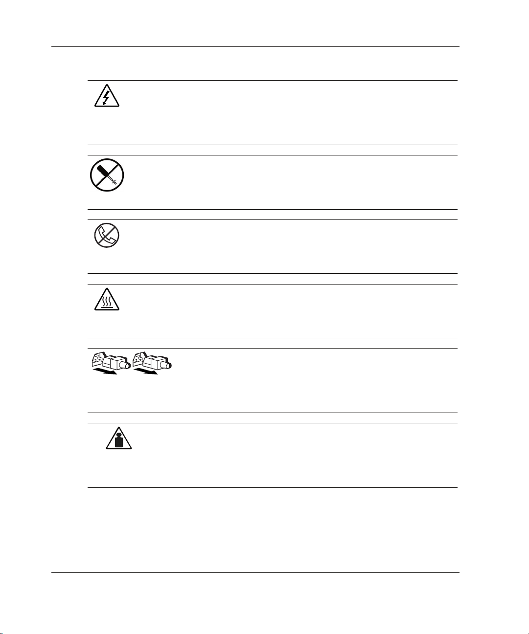
This symbol indicates the presence of hazardous energy circuits or electric
shock hazards. Refer all servicing to qualified personnel.
WARNING: To reduce the risk of injury from electric shock hazards, do not
open this enclosure. Refer all maintenance, upgrades, and servicing to
qualified personnel.
This symbol indicates the presence of electric shock hazards. The area
contains no user or field serviceable parts. Do not open for any reason.
WARNING: To reduce the risk of injury from electric shock hazards, do not
open this enclosure
This symbol on an RJ-45 receptacle indicates a network interface connection.
WARNING: To reduce the risk of electric shock, fire, or damage to the
equipment, do not plug telephone or telecommunications connectors into this
receptacle.
This symbol indicates the presence of a hot surface or hot component. If this
surface is contacted, the potential for injury exists.
WARNING: To reduce the risk of injury from a hot component, allow the
surface to cool before touching.
These symbols, on power supplies or systems, indicate that the
equipment is supplied by multiple sources of power.
WARNING: To reduce the risk of injury from electric shock,
remove all power cords to completely disconnect power from the
system.
This symbol indicates that the component exceeds the recommended
weight for one individual to handle safely.
WARNING: To reduce the risk of personal injury or damage to the
equipment, observe local occupational health and safety requirements
and guidelines for manual material handling.
xii HP ProLiant DL740 Server User Guide
Page 12
Rack Stability
WARNING: To reduce the risk of personal injury or damage to the equipment,
be sure that:
• The leveling jacks are extended to the floor.
• The full weight of the rack rests on the leveling jacks.
• The stabilizing feet are attached to the rack if it is a single-rack installation.
• The racks are coupled together in multiple-rack installations.
• Only one component is extended at a time. A rack may become unstable if
more than one component is extended for any reason.
Symbols in Text
These symbols may be found in the text of this guide. They have the following
meanings.
WARNING: Text set off in this manner indicates that failure to follow directions
in the warning could result in bodily harm or loss of life.
About This Guide
CAUTION: Text set off in this manner indicates that failure to follow directions could
result in damage to equipment or loss of information.
IMPORTANT: Text set off in this manner presents essential information to explain a concept
or complete a task.
NOTE: Text set off in this manner presents additional information to emphasize or supplement
important points of the main text.
HP ProLiant DL740 Server User Guide xiii
Page 13
About This Guide
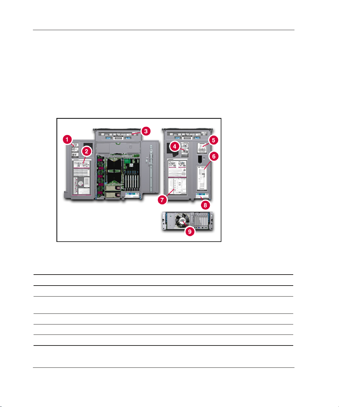
Server Labels
A significant amount of server configuration and options installation information is
provided on the server labels. As shown in Figure 1, these labels are located on the
top of the unit and inside the unit.
NOTE: These labels do not contain warning and caution information. Refer to this guide or to
the option documentation for the applicable warnings and cautions.
Figure 1: Location of server labels
Table 1: Location of Server Labels
Item Component Item Component
1 I/O board removal label 6 I/O board configuration label
2 Hot Plug RAID Memory cartridge operation
label
3 System status LED indicators label 8 Rear connectors label
4 Removing power and media module label 9 Removing host module label
5 Front components label
xiv HP ProLiant DL740 Server User Guide
7 System board components label
Page 14

Related Documents
For additional information on the topics covered in this guide, refer to the following
documentation:
• Rack Resource Kits are included with the racks and include the following
(depending on rack model):
— Rack Products Documentation CD—Available on the HP website or included
with the Rack Resource Kit.
— 10000 Series Rack Resource Kit—Included with all HP 10000 Series racks.
— 9000 Series Products Audio-Visual (AV) CD Kit—Included with the
Compaq branded 9000 Series Rack Resource Kit.
— The Rack 7000/4000 Series Rack Resource Kit—Included with all Compaq
branded 7000 and 4000 Series racks.
— Rack Builder Online—Available on the HP website. Instructions on how to
access and use this online tool are included in the Rack Resource Kit
• Documentation included on the Documentation CD:
About This Guide
— Smart Array 5i Controller User Guide
— ROM-Based Setup Utility User Guide
— Servers Troubleshooting Guide
— PCI Hot Plug Administration Guide
— Integrated Lights-Out User Guide
— Server Online Reference Guide
— Hot Plug RAID Multimedia Virtual Tour for ProLiant DL740 Servers
multimedia demo
• ProLiant DL740 Power Calculator—Available on the ActiveAnswers website at
activeanswers.compaq.com
HP ProLiant DL740 Server User Guide xv
Page 15

About This Guide
Getting Help
If you have a problem and have exhausted the information in this guide, you can get
further information and other help in the following locations.
Technical Support
In North America, call the HP Technical Support Phone Center at 1-800-652-6672.
This service is available 24 hours a day, 7 days a week. For continuous quality
improvement, calls may be recorded or monitored. Outside North America, call the
nearest HP Technical Support Phone Center. Telephone numbers for worldwide
Technical Support Centers are listed on the HP website, www.hp.com.
Be sure to have the following information available before you call HP:
• Technical support registration number (if applicable)
• Product serial number
• Product model name and number
• Applicable error messages
• Add-on boards or hardware
• Third-party hardware or software
• Operating system type and revision level
HP Website
The HP website has information on this product as well as the latest drivers and flash
ROM images. You can access the HP website at www.hp.com.
xvi HP ProLiant DL740 Server User Guide
Page 16

Authorized Reseller
For the name of your nearest authorized reseller:
• In the United States, call 1-800-345-1518.
• In Canada, call 1-800-263-5868.
• Elsewhere, see the HP website for locations and telephone numbers.
Optional Installation Service
You may choose to have HP install your system. The installation service can be
purchased as a Care Pack packaged service or as a customized service agreement to
meet your specific requirements. Care Pack services include:
• Care Pack Installation Services for Hardware
• Care Pack Installation and Start-up Services for Microsoft Windows 2000 and
Windows NT
• Care Pack Installation and Start-up Services for Insight Manager 7
About This Guide
Visit the HP website for detailed descriptions of these Care Pack services. This
method helps ensure top performance from the start and is especially valuable for
business-critical environments.
This optional hardware installation service is available in all countries where HP has
a direct or indirect service presence. Service may be ordered from and directly
provided by an HP authorized service reseller or, in the United States only, service
may be ordered by calling 1-800-652-6672. In the United States, HP makes all of the
arrangements to have the system installed by qualified guaranteed service providers.
For U.S. ordering information, refer to the services website:
h18005.www1.hp.com/services/carepaq/us/install/
For worldwide ordering information, refer to the services website:
h18005.www1.hp.com/services/carepaq/global/
HP ProLiant DL740 Server User Guide xvii
Page 17

About This Guide
Reader’s Comments
HP welcomes your comments on this guide. Please send your comments and
suggestions by e-mail to ServerDocumentation@hp.com.
xviii HP ProLiant DL740 Server User Guide
Page 18

ProLiant DL740 Servers
The ProLiant DL740 server, a high-density enterprise-class and datacenter server,
delivers 8-way scalable performance for 24 x 7 multiserver rack environments. The
ProLiant DL740 server, which is based on F8 architecture, delivers this performance
through Intel® Xeon processor MP technology, scalable performance of I/O and
memory, and high levels of fault tolerance and manageability for the data center.
• Performance is maximized with up to eight Intel Xeon processors MP with
Hyper-Threading technology.
1
Server Features
• The ProLiant DL740 server is equipped with up to 40 GB of Hot Plug RAID
Memory using industry-standard PC133 SDRAM DIMMs (32 GB of addressable
memory). This new technology allows industry-standard DIMMs to be replaced,
added, or upgraded while the server is running.
• Six 64-bit PCI-X slots operating at 100 MHz, all with PCI Hot Plug capability.
• Drive performance enhanced with an embedded Smart Array 5i Controller and
Ultra3 hard drives.
• Integrated Lights-Out (iLO) Standard.
• Two embedded Gigabit Ethernet network interface controllers (NICs) with PXE
support.
HP ProLiant DL740 Server User Guide 1-1
Page 19

Server Features
In addition to Hot Plug RAID Memory, other high-availability features include:
• Redundant array of memory with error checking and correcting (ECC) and
multibit error (MBE) correction
• Fault-tolerant integrated Processor Power Modules (PPM)
• PCI Hot Plug slots
• Redundant hot-pluggable power supplies
• Redundant hot-pluggable fans
• Redundant NIC support
• Smart Array 5i Controller
• Disk drive fault tolerance
• Automatic Server Recovery (ASR-2)
• Dual power cords
Server management and configuration tools important to availability include:
• Hot Plug RAID Memory interface—Diagnostic LEDs and caution alarm
• ROM-Based Setup Utility (RBSU)
• SmartStart
• Redundant ROM images
• System interconnect status indicators
• Insight Manager 7
• Survey Utility
• Online ROM Flash
1-2 HP ProLiant DL740 Server User Guide
Page 20
Server Features
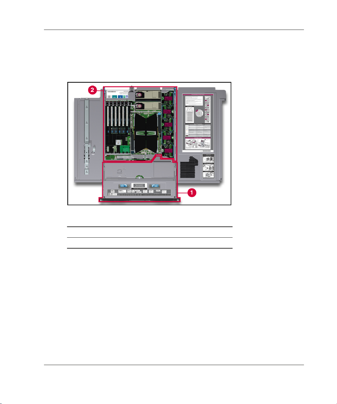
In ProLiant DL740 servers, you can access options and accessories easily through a
top access panel and two removable modules: The host module and the power and
media module. Refer to Figure 1-1, Figure 1-2, and Figure 1-3 for identification of
these modules and other components.
Figure 1-1: Server front view—module location
Item Description
1 Power and media module
2 Host module
HP ProLiant DL740 Server User Guide 1-3
Page 21
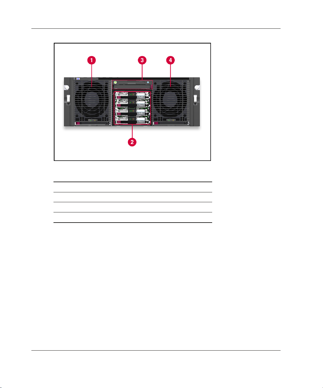
Server Features
Figure 1-2: Server front view—module components
Item Description
1 Power supply 1
2 Hot-plug hard drives
3 Universal media bay
4 Power supply 2
1-4 HP ProLiant DL740 Server User Guide
Page 22
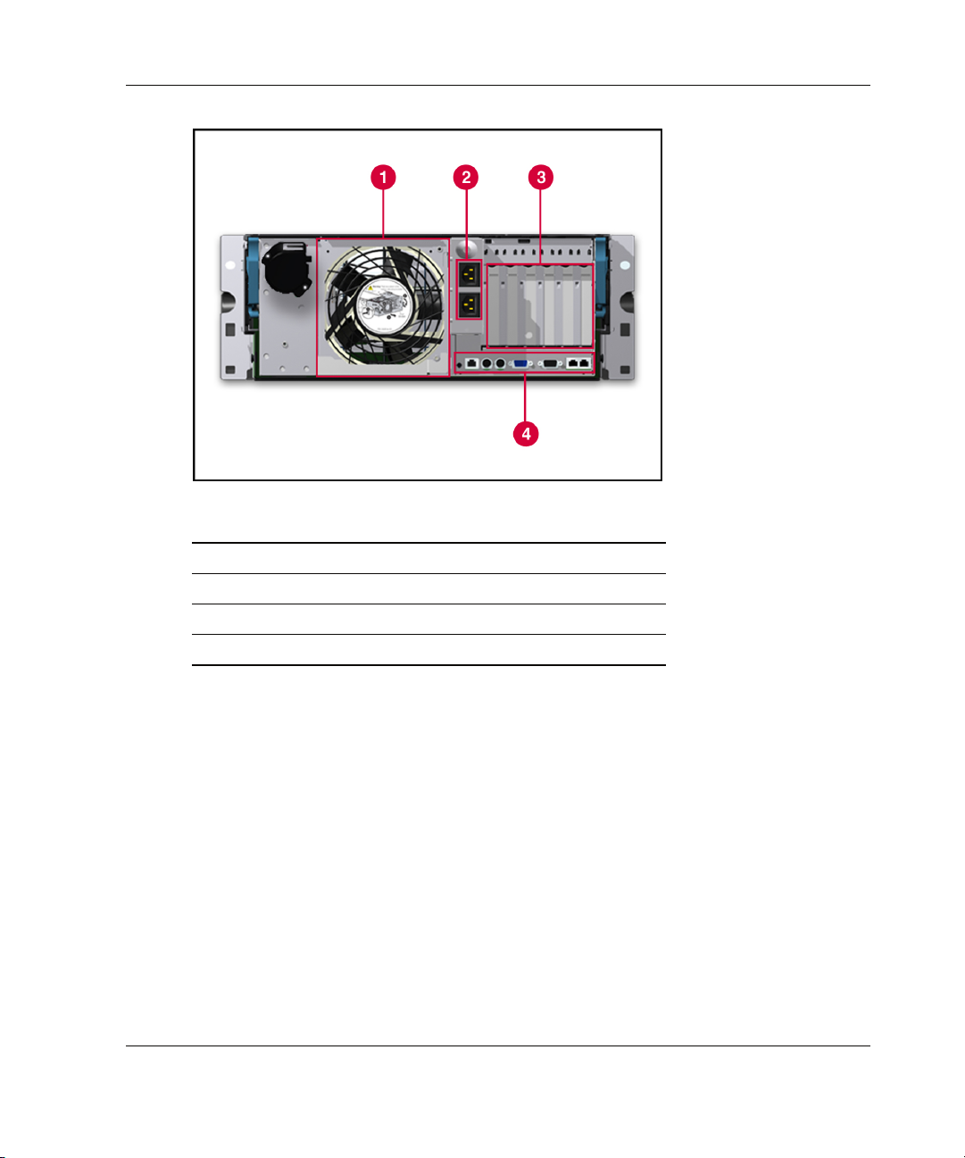
Figure 1-3: Server rear view—module components
Item Description
1 System fans
2 AC power ports
3 I/O expansion slots
4 External connectors
Server Features
HP ProLiant DL740 Server User Guide 1-5
Page 23

Server Features
Standard Features
The following additional features are available on ProLiant DL740 models.
Processors
The server supports four or eight Intel Xeon processors MP with the following
features:
• Easy upgrade capability from a 4P server to an 8P server
• HP designed ZIF sockets with tool-less actuation and tool-less quick release heat
sink clamps
• Keyed, self-aligning heat sink design to protect processor pins and allow for
blind mate assembly
• Pre-attached processor heat sink assembly for easy service and optimum thermals
without having to worry about messy greases
• Fault-tolerant integrated processor power regulation
Each of the processor boards has embedded power, front and back covers for
enhanced thermals and handling, and a single hand rack-and-pinion lever for blind
mate installation in seconds.
Hyper-Threading technology, developed by Intel, improves the performance of IA-32
processors when executing multiple-processor (MP) capable operating systems and
multithreaded applications. With this technology, one physical processor looks like
two logical processors to the operating system and applications. The two logical
processors can execute two separate tasks (or code streams called threads)
concurrently by using shared hardware resources.
Hyper-Threading technology is designed to improve the performance of IA-32
processors by using the multithreaded nature of contemporary operating systems and
server applications in such a way as to increase the use of the on-chip execution
resources available in the Intel NetBurst microarchitecture. The integrated cache
subsystem results in reduced memory access times and increased throughput and
performance of the memory subsystem. Specifically, integrated Level 3 cache, which
is only available on the Xeon processor MP, provides a high-bandwidth path to
memory, increasing throughput for large server workloads.
1-6 HP ProLiant DL740 Server User Guide
Page 24

Hot Plug RAID Memory
The HP memory RAID technology stands for Redundant Array of Industry-Standard
DIMMs. The ProLiant DL740 server supports up to 40 GB of Hot Plug RAID
Memory using industry-standard PC133 SDRAM DIMMs (32 GB of addressable
memory). The DIMMs are installed in five Hot Plug RAID Memory cartridges. Hot
Plug RAID Memory allows for the following server service and management
capabilities while the server is running:
• Memory hot-replace—Allows the replacement of failed DIMMs. This feature is
built into the hardware, is operating system-independent, and requires no drivers.
• Memory hot-add—Allows the addition of extra banks of memory without
powering down the server. This feature requires operating system support and
drivers.
• Memory hot-upgrade—Allows the upgrade of existing DIMMs with
larger-capacity DIMMs without powering down the server. This feature requires
operating system support and HP drivers.
Server Features
HP ProLiant DL740 Server User Guide 1-7
Page 25
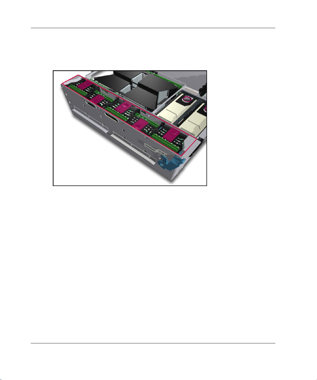
Server Features
The Hot Plug RAID Memory cartridges are located on the inner right side of the host
module. Each memory cartridge contains up to eight DIMMs. Each cartridge has a
protective cover, and a latch and lock.
Figure 1-4: Memory cartridge location
1-8 HP ProLiant DL740 Server User Guide
Page 26

Server Features
The ProLiant DL740 server has five memory cartridges, each consisting of eight
DIMMs. In each memory cartridge, similar DIMMs are installed in bank pairs (1+2,
3+4, 5+6, 7+8) for memory interleaving to increase performance.
Basic memory features include:
• ECC memory with single-bit and MBE correction and detection down to the
failed DIMM level
• Support for standard ECC 133-MHz registered SDRAM
• Driverless hot-replace functionality
• Expandability to 40 GB of Hot Plug RAID Memory using industry-standard
PC133 SDRAM DIMMs (32 GB of addressable memory)
• Support for up to eight memory banks, with each bank consisting of five DIMMs
(one DIMM is for redundancy):
— Each DIMM of a given bank must be of the same size, type, and speed.
— DIMMs are populated in bank pairs for interleaved operation to increase
performance.
NOTE: The DIMM size, type, and speed are defined by the DIMM part number. All
DIMMs in a bank must have the same part number, as indicated by the following example:
123456-12x
All numbers except the last (designated by x) must match for DIMMs to be considered
the same.
• Cartridge and DIMM diagnostic information
HP ProLiant DL740 Server User Guide 1-9
Page 27

Server Features
PCI-X Technology
PCI-X technology leverages the wide acceptance of the PCI bus and provides an
evolutionary I/O upgrade to conventional PCI. PCI-X technology enhances the PCI
protocol and frequency to meet bandwidth needs of enterprise computing systems.
PCI-X provides backward compatibility with the PCI bus at both the expansion board
and system level.
Expansion Slots
The server has six 64-bit PCI-X expansion slots operating at 100 MHz:
• Slots 1 and 2 (PCI bus 7) support PCI-X expansion boards at 100 MHz; it is
keyed for 3.3v signaling.
• Slots 3 and 4 (PCI bus 11) support PCI-X expansion boards at 100 MHz; it is
keyed for 3.3v signaling.
• Bus 5 and 6 (PCI bus 3) support PCI-X expansion boards at 100 MHz; it is keyed
for 3.3v signaling.
NOTE: The operating system detects PCI devices in the following slot order: 5-6-1-2-3-4.
PCI Hot Plug
PCI Hot Plug provides the ability to remove, replace, upgrade, and add PCI/PCI-X
expansion boards without powering down the server. PCI and PCI-X boards can be
placed in a PCI Hot Plug slot. PCI Hot Plug device drivers and operating system
support are required to enable PCI Hot Plug.
A PCI Hot Plug button is located above each PCI/PCI-X slot, providing PCI Hot Plug
control directly at the server without the use of the PCI Hot Plug utility software.
For more information about PCI Hot Plug, refer to the server documentation CD.
1-10 HP ProLiant DL740 Server User Guide
Page 28

Network Interface Controllers
The ProLiant DL740 server is equipped with two embedded Gigabit Ethernet
network interface controllers. Each of these 10/100/1000 Base TX UTP 100-MHz
64-bit PCI-X NICs have the following features:
• Two RJ-45 connectors for 10BaseT, 100BaseTX, or 1000BaseTX Ethernet
• Preboot eXecution Environment (PXE) support
Redundant NIC software, located on the SmartStart CD, supports a redundant NIC
configuration. This feature may be used with one dual-port, two single-port, or two
dual-port NICs.
Disk Controller
The ProLiant DL740 server provides an embedded Smart Array 5i Controller. Refer
to Chapter 8 for more information about the features and array setup procedures for
the controller. The disk controller has 32 MB of read data cache.
The Smart Array 5i Controller supports Ultra3 SCSI hard drives. Ultra3 is the next
generation of high performance SCSI technology that offers data transfer speeds of
up to 160 MB/sec. It is a term that is synonymous with Ultra160 SCSI and describes
any device that combines Ultra2 SCSI with Cyclic Redundancy Check (CRC),
domain validation, and double transition clocking. HP Ultra3 universal hot-pluggable
hard drives provide this level of performance in addition to compatibility with HP
ProLiant servers, AlphaServer, and StorageWorks Enclosure 4200 solutions.
Server Features
Ultra320 SCSI hard drives will run at Ultra3 speeds unless you install an optional
Ultra320 Array Controller and the Twisted Pair Cable Array Bypass kit included with
the system.
HP ProLiant DL740 Server User Guide 1-11
Page 29

Server Features
Internal Hot-Plug Drive Bays
The internal hot-plug drive bays support four one-inch Ultra3 SCSI hard drives.
Drives may be of any storage capacity but must be mounted on HP universal drive
carriers (hot-plug drive trays).
Universal Media Bay
The universal media bay supports hot-pluggable IDE devices and ships standard with
a DVD-ROM drive. The bay also supports other removable media devices, such as a
CD-ROM drive.
Video
The Integrated PCI Video Controller with 8 MB of video RAM can obtain a
maximum resolution of 1280 x 1024 in 32-bit true color. The PCI video controller
supports:
• 16 to more than 256 colors, depending on graphics mode.
• SVGA, VGA, and EGA graphics resolution.
Redundant Hot-Plug Power Supplies
The ProLiant DL740 server supports 1100/800-W redundant hot-plug power
supplies.
• Power supplies are load balancing.
• The ProLiant DL740 server supports up to two power supplies. Refer to the
“Power Requirements” section of Chapter 2 to determine power supply
requirements.
• Power supplies must be run at highline (200-240 VAC) for redundancy.
1-12 HP ProLiant DL740 Server User Guide
Page 30

Redundant Hot-Plug Fans
ProLiant DL740 servers include 1 + 1 redundant hot-plug fans. If a fan fails, the
server generates a system alert and triggers the redundant fan to take over
automatically. The redundant hot-plug system fans protect the various server
components from overheating and possibly causing a system interruption.
Diagnostic LEDs exist near each fan and on the front of the server. For more
information on the hot-plug fan LEDs, refer to Appendix D.
Supported Interfaces
Supported interfaces that ship standard in the server include:
• Serial connector
• Video port
• Keyboard connector
• Mouse connector
Server Features
• Two RJ-45 server local area network (LAN) connectors (10/100/1000 Ethernet)
• iLO LAN connector (10/100 management)
• Universal serial bus (USB) port
HP ProLiant DL740 Server User Guide 1-13
Page 31

Server Features
Optional Features
The ProLiant DL740 server supports a wide range of server hardware options. HP
server options are available from an HP authorized reseller or HP authorized service
provider. Additional information about HP servers and options can be found in the
QuickSpecs on the HP website.
This guide also provides basic installation instructions for the following server
options:
• Dual Inline Memory Modules (DIMMs)
• Processor board with Intel Xeon processors MP
• Hot-plug Ultra3 or Ultra320 SCSI hard drives
• I/O expansion boards (including PCI-X expansion boards with PCI Hot Plug
driver support)
• Intelligent Fibre Channel host bus adapters (HBAs)
• Integrated Smart Array Bypass Kit (included with the server)
• Smart Array Controllers
NOTE: Hardware option installation instructions can be found inside each hardware option kit.
Supported Operating Systems
For a list of operating systems that are supported on the ProLiant DL740 server, refer
to the ProLiant OS Support Matrix located on the Web:
ftp://ftp.compaq.com/pub/products/servers/os-support-matrix-310.pdf
1-14 HP ProLiant DL740 Server User Guide
Page 32

Server Features
Server Configuration and Management Features
HP offers an extensive set of features and tools to support effective server
configuration and management, including:
• SmartStart
• RBSU
• iLO Standard Management
• Redundant ROM images
• Advanced data guarding (RAID ADG)
• HP utilities for Microsoft Windows
• HP utilities for Linux
• Insight Manager 7
• Integrated Management Log (IML)
SmartStart
SmartStart, which is located on the SmartStart CD, allows you to configure your HP
server and load operating system software. SmartStart uses a step-by-step process to
configure the server and load the system software, thereby achieving a wellintegrated server to ensure maximum dependability and supportability.
For information about SmartStart, refer to the ProLiant Essentials Foundation Pack
included in the shipping box.
HP ProLiant DL740 Server User Guide 1-15
Page 33

Server Features
ROM-Based Setup Utility
RBSU automatically configures the system based on the selected operating system.
RBSU supports a wide range of configuration customization features, including:
• Selection of a primary operating system from a list of supported
operating systems
• Selection of a Primary Boot Controller from a list of installed mass
storage devices
• Configuration of embedded system devices, such as serial and mouse ports
• Configuration of standard interrupts (IRQs) for PCI devices
• Setting of date and time
• Automatic resolution of resource conflicts in areas such as port addresses
and IRQs
• Storage of configuration in nonvolatile memory
The RBSU is pre-installed in the embedded system ROM on the server. The RBSU
has embedded support for English, French, German, Italian, Spanish, and
Japanese languages.
NOTE: Systems that use RBSU do not support the System Configuration Utility. For more
information on using RBSU, refer to the ROM-Based Setup Utility User Guide located on the
documentation CD.
1-16 HP ProLiant DL740 Server User Guide
Page 34

Integrated Lights-Out Standard Management
Integrated Lights-Out (iLO) is an HP engineered application-specific integrated
circuit (ASIC) that embodies industry-leading Lights, -Out management functionality
on the ProLiant DL740 server.
Features
iLO Standard includes basic system board management functions, diagnostics, and
essential Lights-Out functionality. iLO Standard is provided as standard on all
ProLiant DL740 servers.
iLO features include:
• iLO is built into every ProLiant DL740 server; no slot is needed.
• iLO is easy to setup and easy to use.
• iLO is always on via server auxiliary power, and it is always running regardless
of the state of the server.
• iLO offers sophisticated security features, including industry-standard SSL.
Server Features
iLO Advanced can be licensed with the optional iLO Advanced Pack. iLO Advanced
offers sophisticated virtual administration features.
iLO Standard Features
iLO Standard is an integrated component in the ProLiant DL740 server and provides:
• Text-based console
• Virtual power button and reset
• Virtual indicators
• Event logs (IML and iLO log)
• Remote Diagnostics (iLO and server)
• Automatic Server Recovery
• Agent integration
HP ProLiant DL740 Server User Guide 1-17
Page 35

Server Features
• Alert forwarding and administration
• Remote firmware update
• SSL security
iLO Advanced Features (Optional)
The iLO Advanced option provides:
• Virtual floppy drive
• Virtual graphical console
• Virtual CD
• Directory services (future support)
• PKI support (future support)
IMPORTANT: To use the iLO Advanced Features, you must purchase a license key for the
Integrated Lights-Out Advanced Pack. For more information on the Integrated Lights-Out
Advanced Pack, refer to www.hp.com/servers/lights-out.
Redundant ROM Images
This server is equipped with a redundant ROM that enables the system to recover the
last known good system ROM if the current system ROM has been corrupted. When
the server leaves the factory, both system ROMs contain the same image.
The ProLiant DL740 server also has redundant boot block ROM that allows you to
upgrade the boot block image without the risk of compromising the server. This
redundancy enables you to recover the permanent factory boot block ROM image if
the current boot block ROM has been corrupted.
1-18 HP ProLiant DL740 Server User Guide
Page 36

Smart Components for Online ROM Flash
Online ROM flash technology consists of a combination of components that allow
system administrators to upgrade system or option ROM images across a wide range
of HP servers and server options while the server is running. The ROM upgrades are
performed locally or across a network from a single point of execution and are
flashed individually or grouped together to perform multiple ROM upgrades in a
single step.
HP Smart Components for ROM Flash include installation logic that automatically
checks for hardware, firmware, and operating system dependencies, installing only
the correct ROM upgrades required by each target server.
Advanced Data Guarding
As storage capacities continue to rapidly expand, disk drive fault protection becomes
more important. This fault protection needs to be implemented without doubling the
investment in disk drives or a new storage infrastructure. Currently, RAID 5 is only
recommended for protecting up to 14 disk drives in an array. RAID 1 provides
greater fault protection, but requires every drive to be mirrored, so it is often too
costly to implement on large RAID volumes. Customers want the protection of
RAID 1 or better with an implementation cost similar to RAID 5.
Server Features
With Advanced Data Guarding (RAID ADG), you can safely and economically
protect a RAID volume of up to 2 TB and a total of 56 disk drives. RAID ADG offers
fault protection greater than RAID 1 or RAID 5 and only consumes the capacity of
one additional disk drive for each distributed parity data drive.
RAID ADG is essentially an extension of RAID 5, which allows for additional fault
tolerance by using a second independent distributed parity scheme. Data is striped
across a set of drives, just as in RAID 5, and a second set of parity is calculated and
written across all the drives. RAID ADG provides high data fault tolerance and can
sustain multiple simultaneous drive failures. This solution is important for protecting
mission-critical data.
RAID ADG provides a much higher level of fault tolerance than RAID 5. RAID
ADG allows two simultaneous drive failures without downtime or data loss, while
RAID 5 only allows one drive failure.
HP ProLiant DL740 Server User Guide 1-19
Page 37

Server Features
Only the Smart Array 5300 Controllers support RAID ADG. The Smart Array
5304/128 is shipped with RAID ADG and is available as an upgrade option for the
Smart Array 5302/32 and 5302/64.
For more information about RAID ADG, refer to the storage controller
documentation at:
www.compaq.com/products/servers/proliantstorage/arraycontrollers/
docs/index.html#tech
HP Utilities for Microsoft Windows
HP servers running Windows can take advantage of several utilities that provide
detailed system information, including:
• Array Configuration Utility (ACU)
• Integrated Management Log Viewer
These utilities are provided on the ProLiant Support Pack for Microsoft
Windows 2000 and the ProLiant Support Pack for Microsoft Windows Server 2003.
HP Utilities for Linux
HP servers running Linux can take advantage of several utilities that provide detailed
system information, including:
• Array Configuration Utility for Linux
• Compaq Storage Agents for Linux
• Insight Diagnostics
• Lights-Out Drivers and Agents for Linux
• NIC Agents for Linux
• Red Hat GL Utility Toolkit (GLUT)
• Server Management Drivers and Agents
These utilities are provided on the ProLiant Support Pack for Linux operating system.
1-20 HP ProLiant DL740 Server User Guide
Page 38

HP has an array of Opensource projects for Linux. For more information on HP
Opensource projects refer to:
opensource.hp.com/
HP only supports servers configured with certified Linux operating system versions
found on the Linux server certification matrix website:
h18000.www1.hp.com/products/servers/linux/hplinuxcert.html
Insight Manager 7
Insight Manager 7 is a systems management tool that provides performance,
configuration, and fault management for HP servers and clients. Insight Manager 7
has two components:
• Insight Manager 7 software, which runs on the management console
• Management Agents (operating system specific), which run on the server or
managed desktop client
Server Features
Insight Manager 7 features an easy-to-use graphical interface and includes online
documentation and context-sensitive help. Key features include:
• Server fault condition alerts
• Server performance and fault condition monitoring
• Server security and configuration control
• Remote control of the server
• Rapid recovery services
For more information on Insight Manager 7, refer to the Management CD that
shipped with your server.
HP ProLiant DL740 Server User Guide 1-21
Page 39

Server Features
Integrated Management Log
The Integrated Management Log (IML) records all system events and stores them in
an easily viewable form. These events are recorded and marked with a time stamp.
For more information about the IML, refer to the “Integrated Management Log”
section in Chapter 9.
Diagnostic Tools
Software, firmware, and hardware diagnostic features of the
ProLiant DL740 server include:
• Diagnostic LED indicators that are all viewable from the exterior of the server
• Diagnostic alarms that are audible from the exterior
• POST messages
• Memory Configuration Error Diagnostics
• Server diagnostics (DIAGS)
• ROMPaq utilities to upgrade flash ROMs
• ACU
• IML
For information about diagnostic tools, refer to either the HP
Servers Troubleshooting Guide on the server documentation CD or to Appendix E.
1-22 HP ProLiant DL740 Server User Guide
Page 40

Security Features
The following sections outline the security features available for the
ProLiant DL740 server.
Software Security
The following software security features are established through RBSU:
• Administrator password—Prevents changes to the configuration unless you enter
the password.
• Diskette drive control—Enables and disables the diskette drive. When disabled,
the diskette drive will not read, write, or boot.
• Diskette write control—Enables and disables diskette write functions. When
disabled, the drive will not write, but boot and read functions are still available.
• Power-on password—Locks out the keyboard to prevent unauthorized access to
servers. The keyboard lockout prevents logins or commands until the proper
password is entered.
Server Features
• Network server mode—Permits system startups from a hard disk or network
server while the keyboard and mouse are disabled.
• QuickLock—Disables the keyboard and mouse without exiting the application.
The application remains in view on the monitor screen, but cannot be accessed.
• Serial interface control—Disables the serial port. When disabled, all data transfer
through the integrated serial port is blocked.
HP ProLiant DL740 Server User Guide 1-23
Page 41

Server Features
Hardware Security
The ProLiant DL740 server has a switch on the I/O board that establishes the
following hardware security features:
• Configuration (NVRAM) lock—Disallows configuration changes when enabled
by preventing nonvolatile memory from being modified.
• Diskette boot control—Enables and disables the diskette boot functions. When
disabled, the system will not boot from a diskette, but runtime diskette read and
write functions are still available.
Server Registration
Registering the server provides HP with valuable information about server
installation. This information helps HP serve your needs better now and in the future.
To register, visit the HP website:
register.hp.com
To register to receive Product Change Notifications (PCNs), visit:
www.hp.com/united-states/subscribe/
To register with our ActiveUpdate page and receive software component delivery:
h18000.www1.hp.com/products/servers/management/activeupdate/
1-24 HP ProLiant DL740 Server User Guide
Page 42

Routine Maintenance
For information about routine maintenance and safety precautions, refer to the server
documentation CD included with your server.
Server Features
HP ProLiant DL740 Server User Guide 1-25
Page 43

Server Features
Warranty
Warranty features include:
• Three-Year Parts, Labor, and On-Site Limited Warranty with next business day
response
• Pre-Failure Warranty on processors, memory, and hard drives (requires
installation of Insight Manager 7
For additional service and support offerings, visit the HP website:
)
www.hp.com
1-26 HP ProLiant DL740 Server User Guide
Page 44

2
Installing the Server in a Rack
This chapter specifies the procedures required to install a ProLiant DL740 server in
an HP or industry-standard 19-inch rack.
Figure 2-1: ProLiant DL740 server
HP ProLiant DL740 Server User Guide 2-1
Page 45

Installing the Server in a Rack
Rack Installation Overview
Installing the ProLiant DL740 server in a rack requires the following steps (detailed
later in this chapter):
1. Select a site and unpack the server. Refer to the “Selecting a Site” and “Shipping
Box Contents” sections in this chapter.
2. Remove the host module and power and media module to lighten the chassis.
Refer to the hood labels and to Chapter 3 for host module and media and power
module removal instructions.
3. Install any expansion boards or other options such as additional memory.
NOTE: Refer to Chapter 4 and Chapter 5 to install other options.
4. Install the chassis in the rack and replace the modules.
NOTE: Refer to the rack template included with the server for more details on installing
the server into a rack.
5. Connect the keyboard, mouse, monitor, network, storage, and power cords. Refer
to Chapter 6.
2-2 HP ProLiant DL740 Server User Guide
Page 46

Selecting a Site
When installing the ProLiant DL740 server in a rack, the following standards
must be met:
• Space and airflow requirements
• Power requirements
• Grounding requirements
• Temperature requirements
Space and Airflow Requirements
To allow for servicing and adequate airflow, observe the following spatial
requirements when deciding where to install a rack:
• Leave a minimum clearance of 63.5 cm (25 inches) in front of the rack.
• Leave a minimum clearance of 76.2 cm (30 inches) behind the rack.
• Leave a minimum clearance of 121.9 cm (48 inches) from the back of the rack to
the back of another rack or row of racks.
Installing the Server in a Rack
HP servers draw in cool air through the front door and expel warm air through the
rear door. Therefore, the front and rear rack doors must be adequately ventilated to
allow ambient room air to enter the cabinet, and the rear door must be adequately
ventilated to allow the warm air to escape from the cabinet.
CAUTION: To prevent improper cooling and damage to the equipment, do not block
the ventilation openings.
When vertical space in the rack is not filled by a server or rack component, the gaps
between the components cause changes in airflow through the rack and across the
servers. Cover all gaps with blanking panels to maintain proper airflow.
HP ProLiant DL740 Server User Guide 2-3
Page 47

Installing the Server in a Rack
CAUTION: Always use blanking panels to fill empty vertical spaces in the rack. This
arrangement ensures proper airflow. Using a rack without blanking panels results in
improper cooling that can lead to thermal damage.
Compaq branded 9000 and 10000 Series racks provide proper server cooling from
flow-through perforations in the front and rear doors that provide 64 percent open
area for ventilation.
CAUTION: If a third-party rack is used, observe the following additional
requirements to ensure adequate airflow and to prevent damage to the equipment:
• Front and rear doors—If the 42U server rack includes closing front and rear
doors, you must allow 5,350 sq cm (830 square inches) of holes evenly
distributed from top to bottom to permit adequate airflow (equivalent to the
required 64 percent open area for ventilation).
• Side—The clearance between the installed rack component and the side panels
of the rack must be a minimum of 7 cm (2.75 inches).
CAUTION: When using a Compaq branded 7000 Series rack, you must install the
high airflow rack door insert [P/N 327281-B21 (42U) or P/N 157847-B21 (22U)] to
provide proper front-to-back airflow and cooling.
2-4 HP ProLiant DL740 Server User Guide
Page 48
Power Requirements
WARNING: To reduce the risk of personal injury, fire, or damage to the
equipment, do not overload the AC supply branch circuit that provides power
to the rack. Consult the electrical authority having jurisdiction over your
facility wiring and installation requirements.
IMPORTANT: Because of the 100 to 240 VAC electrical rating of each power supply, some
local electrical authorities may require either one 15-Ampere circuit for each power supply or
one 20-Ampere circuit for both power supplies.
• The power load needs to be balanced between available AC supply
branch circuits.
• The overall system AC current load must not exceed 80 percent of the branch
circuit AC current rating.
• If a power strip is used, the load should not exceed 80 percent of the power strip
marked electrical current rating.
NOTE: For server specifications, refer to Appendix F.
Installing the Server in a Rack
The installation of this equipment must be in accordance with local or regional
electrical regulations governing the installation of Information Technology
Equipment by licensed electricians. This equipment is designed to operate in
installations covered by the National Electric Code (ANSI/NFPA 70, 1999) and the
code for Protection of Electronic Computer/Data Processing Equipment
(ANSI/NFPA 75, 1992).
For electrical power ratings of options, refer to the product rating label or user
documentation supplied with those options.
IMPORTANT: There is a limited maximum configuration if using 110V input line voltage on
the ProLiant DL740 server. To estimate the power requirements for a specific server
configuration, use the ProLiant DL740 Server Power Calculator located on the ActiveAnswers
Online Solutions website: activeanswers.compaq.com
HP ProLiant DL740 Server User Guide 2-5
Page 49

Installing the Server in a Rack
Power Supplies
The following requirements apply to power supplies:
• The ProLiant DL740 server has two hot-plug, redundant power supplies.
Depending on the system load configuration and input voltage (110 or 220),
more than one power supply may be required to power the system.
• Power supplies are load balancing.
• Power supplies must be run at highline (200−240 VAC) for redundancy.
To estimate the power requirements for a specific server configuration, use the
ProLiant DL740 Server Power Calculator located on the ActiveAnswers Online
Solutions website:
activeanswers.compaq.com
1. Select System Configurator under Tools.
2. Click Select Product Family and select ProLiant Servers.
3. Select ProLiant DL740 Server from the list.
The subsequent Web pages contain information and a link to the ProLiant DL740
Power Calculator.
Power supply advanced features include auto line sensing, which means that no
switch is needed to select the appropriate line voltage.
NOTE: Power supplies provide 1100 watts of power to the system from highline
(200−240 VAC) input line voltage and 800 watts of power from lowline (100−120 VAC) input
line voltage.
2-6 HP ProLiant DL740 Server User Guide
Page 50

Grounding Requirements
WARNING: To reduce the risk of electrical shock from high leakage currents, a
reliable, grounded (earthed) connection is essential before connecting the unit
to an AC supply.
For proper operation and safety, this equipment is required to be correctly grounded.
In the United States, install the equipment in accordance with ANSI/NFPA 70, 1999,
Article 250, and with any local and regional building codes. In Canada, the
equipment should be installed in accordance with Canadian Standards Association,
CSA C22.1, Canadian Electrical Code. In all other countries, the installation should
follow any regional or national electrical wiring codes, such as the International
Electrotechnical Commission (IEC) 364, parts one through seven. All power
distribution devices used in the installation, including branch wiring, receptacles, and
so on, should be Listed or Certified ground-type devices.
Due to the higher ground leakage currents associated with the equipment, HP
recommends the use of a Power Distribution Unit (PDU) that provides a
supplementary ground conductor. This supplementary ground conductor should be
permanently connected to a suitable building ground terminal. The use of common
power outlet strips for this equipment is not recommended.
Installing the Server in a Rack
HP ProLiant DL740 Server User Guide 2-7
Page 51

Installing the Server in a Rack
Temperature Requirements
To be sure of continued safe and reliable operation of the equipment, install the
system in a well-ventilated, climate-controlled environment.
The HP Maximum Recommended Ambient Operating Temperature (TMRA) for
most server products is 35° C (95° F). The temperature in the room where the rack is
located should not exceed 35° C (95° F).
The operating temperature inside the rack will always be higher than the room
temperature and is dependent on the configuration of equipment in the rack. The
TMRA for each piece of equipment should be checked before installation. The
maximum internal rack temperature for the configuration should not exceed the
values shown in Table 2-1.
Table 2-1: Rack Internal Temperature Maximums
Equipment Included
Rack-mountable ProLiant
DL740 servers
HP rack-mountable options 35° C (95° F)
Other manufacturers’ options
Maximum Internal Rack
Temperature
35° C (95° F)
Refer to other manufacturers’
specifications
CAUTION: To reduce the risk of damage to the equipment when installing
third-party options:
• Be sure that the optional equipment does not impede airflow to the
rack-mountable ProLiant DL740 servers or increase the internal rack
temperature beyond the HP specified maximum rating.
• Be sure that the Manufacturer’s TMRA for the optional equipment is not
exceeded when the equipment is installed in the rack.
2-8 HP ProLiant DL740 Server User Guide
Page 52

Shipping Box Contents
Unpack the shipping boxes by following the instructions and illustrations printed on
the outsides of the boxes. The shipping boxes contain the following materials:
• ProLiant DL740 server
— Hood labels contain most of the option installation and setup
— Torx tool is located inside the host module of the server
• Country kit
— AC power cords
— Hardware documentation and software packs, including ProLiant Essentials
Foundation Pack, reference information, and software products
• Hardware kit
— Rack template contains rack installation instructions
— Server rack rails
— Cable management system
Installing the Server in a Rack
— Integrated Array Bypass kit
In addition to the supplied items, you may need the following unsupplied items to
complete the installation:
• Options to be installed, such as expansion boards, monitors, uninterruptible
power supplies (UPSs), hard drives, hard-drive cages, tape drives, processor
boards, or additional memory
• Application software
HP ProLiant DL740 Server User Guide 2-9
Page 53

Installing the Server in a Rack
Rack Considerations
Consider the following issues when working with server rack systems.
Rack Stability
Rack stability is of special concern when equipment is routinely installed, removed,
or accessed within the rack. Stability is achieved through the use of leveling feet
(jacks), stabilizers, and ballast kits.
Leveling Feet (Jacks)
Leveling feet are adjustable stabilizers that level the cabinet at the installation site
and take the balance off of the wheels.
Stabilizers
The anti-tip stabilizer provides stability and support when equipment is installed,
removed, or accessed within the rack. HP recommends that you use a stabilizer
option kit with a stand-alone rack.
Ballast Kits
Ballast kits can be added to a cabinet to increase side-to-side and front-to-back
mechanical stability. Lightly loaded cabinets may require ballast to keep them from
tipping over when a force is applied to the side of the cabinet. Heavily loaded
systems, depending on the particular configuration involved, usually do not require
ballast.
To be sure of rack stability, the minimum weight of the installed equipment should
be 114 kg (210 lb). Ballast kits should be added if a system has less than 114 kg
(210 lb) minimum weight. In addition, ballast kits should be installed if any single
system component weighs over 45 kg (100 lb) such that a minimum of 91 kg (200 lb)
of ballast and equipment remains in place when the component is extended from the
rack.
2-10 HP ProLiant DL740 Server User Guide
Page 54

A single ProLiant DL740 server typically weighs between 48 and 61 kg (105 and
135 lbs), depending on configuration. If a single ProLiant DL740 server is the only
component installed in a rack, you must add two ballast kits. Each kit contains two
18 kg (40 lb) ballasts. Two ballast kits (a total of four ballasts) equal 73 kg (160 lb),
bringing the total up to a minimum of 136 kg (300 lb).
If two ProLiant DL740 servers are the only components installed in a rack, you must
add a single ballast kit, which maintains a minimum weight of 91 kg (200 lbs)
remaining in the rack when one of the servers is extended.
For more information, refer to any additional installation documentation provided
with the rack.
Warnings and Precautions
Before beginning the following procedures, be sure that you understand these
warnings:
WARNING: To reduce the risk of personal injury or damage to the
equipment:
48-61 kg
105-135 lbs
• Observe local occupational health and safety requirements and
guidelines for manual material handling.
• Obtain adequate assistance to lift and stabilize the chassis during
installation or removal.
• Understand that the product will be unstable when not fastened to
the rails.
Installing the Server in a Rack
• Remove all hot-plug power supplies and drives to reduce the
overall weight of the product.
HP ProLiant DL740 Server User Guide 2-11
Page 55
Installing the Server in a Rack
WARNING: To reduce the risk of personal injury or damage to the equipment,
be sure that:
• The leveling jacks are extended to the floor.
• The full rack weight rests on the leveling jacks.
• The stabilizing feet are attached to the rack if it is a single rack installation.
• The racks are coupled together in multiple rack installations.
• A rack may become unstable if more than one component is extended for
any reason. Extend only one component at a time.
CAUTION: To maintain optimum cooling, a perforated rack door must be used with
this server. Failure to use a properly ventilated door results in thermal damage to the
server. Compaq 7000 series racks require an upgraded door. To order a high-airflow
perforated door from HP, request P/N 327881-B21 for a 42U rack, or P/N
157847-B21 for a 22U rack.
IMPORTANT: To reduce the overall weight of the system, HP recommends that the host
module and the power and media module be removed from the server before loading it onto
the rails.
IMPORTANT: Refer to the following rack documentation for further cautions:
• 9000 Rack Series Products Audio-Visual (AV) CD Kit (shipped with HP racks)
• Rack Builder Pro Configuration Tool CD (available on the HP website or ordered with the
Rack Resource CD Kit)
• Rack Products Documentation CD (available on the HP website or ordered with the Rack
Resource CD Kit)
• The Rack 7000/4000 Series Rack Resource CD Kit ships with all Compaq 7000 and 4000
Series Racks.
2-12 HP ProLiant DL740 Server User Guide
Page 56

Installing the Server in a Rack
Preparing the Rack for Server Installation
To prepare the rack for a server installation:
• Measure with the rack template
• Install the rack rail assemblies
Measuring with the Rack Template
The rack template provides an easy and reliable way to properly position the rack rail
assemblies in the rack.
• The template is two-sided and is printed with arrows that show you where to
insert rack rail assemblies on the front and back of the rack.
• Use a pencil to mark the top and bottom edges of the template against the rack
supports, identifying where the server fits and providing a starting point for
installing the next unit.
WARNING: Always mount the heaviest item on the bottom of the rack and
work from the bottom to the top.
WARNING: Reduce the risk of personal injury or damage to the equipment by
ensuring that the rack leveling feet extend to the floor and support the full
weight of the rack. Each rack must be level and stable. Racks that are not
coupled require stabilizers. This must be done before you perform any work on
the rack.
Refer to the Rack Planning and Installation Guide on the Documentation CD
that accompanies the Compaq branded rack for more information on leveling
feet and stabilizers.
IMPORTANT: Determine where in the rack to place the server before you start installing the
rack rail assemblies. To remind you of the proper placement of the server in the rack, refer to
the Rack Builder report you printed when you planned your rack configuration with the Rack
Builder tools provided with your Compaq branded rack.
HP ProLiant DL740 Server User Guide 2-13
Page 57

Installing the Server in a Rack
To identify the required space and location for the server with the template:
1. Identify the front side of the template.
2. Starting at the bottom of the rack, or at the top of a previously mounted
component, secure the template against the front of the rack by pressing the two
push tabs. Match the hole pattern on the template with the holes on the vertical
rails of the rack.
Figure 2-2: Measuring with the template
3. Align the template so that the sides of the template are even with the sides of the
rack. Tick marks on the vertical rails of the rack designate U-spaces in the rack
configuration and help you maintain the proper alignment.
2-14 HP ProLiant DL740 Server User Guide
Page 58

Installing the Server in a Rack
4. Using a pencil, mark the locations on the rack where you insert the rack rail tabs.
5. On the rack, mark the top and bottom edges of the template . This step helps you
align a template for the next component.
6. Move to the rear of the rack and turn the template over so you can use the
backside of the template.
7. Repeat steps 2 through 5 with the back of the template on the rear of the rack.
IMPORTANT: On the rear of the rack, make pencil marks on the inside of the vertical
rails. These markings guide you in installing rack rails in the interior of the rack frame.
8. Remove the template from the rack.
HP ProLiant DL740 Server User Guide 2-15
Page 59
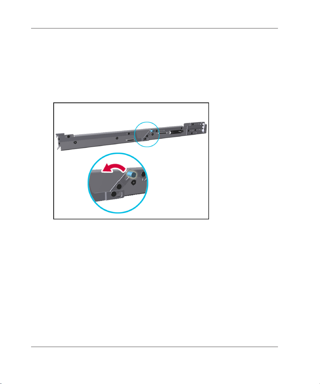
Installing the Server in a Rack
Installing the Rack Rail Assemblies
To install the rack rail assemblies in the rack:
1. From the front of the rack, identify the rear rack holes on the inside of the
vertical rack that you marked with the template.
2. Pull the rail compression lever toward you.
Figure 2-3: Pulling the rail compression lever
2-16 HP ProLiant DL740 Server User Guide
Page 60

Installing the Server in a Rack
3. Insert the two rail tabs from the end of the rack rail assembly into the marked
holes on the inside of the rear of the rack.
Figure 2-4: Inserting the rail tabs on the rear of the rack
4. Adjust the rack rail depth by sliding it forward.
HP ProLiant DL740 Server User Guide 2-17
Page 61

Installing the Server in a Rack
5. Insert the two rail tabs from the rack rail assembly into the marked holes on the
inside of the front of the rack.
Figure 2-5: Inserting the rail tabs on the front of the rack
6. Release the rail compression lever to seat the tabs in the rack post.
7. Repeat steps 1 through 6 for the other rail.
Preparing the Server for Rack Installation
To prepare the server for rack installation:
• Attach the server rails
• Lighten the chassis
2-18 HP ProLiant DL740 Server User Guide
Page 62

Attaching the Server Rails
To attach the server rails to the ProLiant DL740 server chassis:
IMPORTANT: Install the server rails with the smooth side of the rail against the server
chassis.
1. Align the four keyholes on one of the server rails above the four spools on the
side of the chassis.
2. Press the rail against the side of the chassis and slide the rail toward the front of
the server to snap and lock the rail into place.
Installing the Server in a Rack
Figure 2-6: Attaching a server rail to the chassis
IMPORTANT: Be sure that the first rail is firmly anchored to the chassis before attaching the
second rail.
3. Repeat steps 1 and 2 to secure the second rail to the server.
HP ProLiant DL740 Server User Guide 2-19
Page 63

Installing the Server in a Rack
Lightening the Chassis
To make moving and lifting the server more manageable, HP recommends removing
the server modules to lighten the chassis.
WARNING: Each server module weighs more than 16 kg (35 lb). Before
removing the server modules, remove the processor boards and power
supplies to lighten the modules before handling, or have at least two people
handle the modules together.
1. Remove the host module as shown in the “Removing the Host Module” section
of Chapter 3.
2. Remove the power and media module as shown in the “Removing the Power and
Media Module” section of Chapter 3.
2-20 HP ProLiant DL740 Server User Guide
Page 64

Installing the Server in the Rack
To complete the server rack installation, load the server onto the rack rails and
reinstall the server modules.
Loading the Server onto the Rack Rails
WARNING: To avoid destabilizing the rack, install servers starting from the
bottom of the rack.
To install the server in the rack:
1. Pull the inner slide rail forward from each rack rail assembly until it locks into
place (1).
2. Slide the inner bearing brace forward until it stops (2).
Installing the Server in a Rack
Figure 2-7: Locking the inner slide rails into place
HP ProLiant DL740 Server User Guide 2-21
Page 65

Installing the Server in a Rack
3. Use two people to lift the server by its four lift handles (1) and carefully align the
open ends of the server rails on the rear of the server with the extended bearing
brace and inner slide rail of the rack rail assemblies (2).
4. Insert the server rails into the extended inner slide rails on both sides, and then
slowly slide the server into the rack. Continue sliding the server backward until
the rail-release levers engage the rack rail assemblies (3).
Figure 2-8: Loading the server onto the rack rails
CAUTION: Keep the server parallel to the floor when sliding the server rails into the
standard rack rails. Tilting the server up or down can damage the rails.
2-22 HP ProLiant DL740 Server User Guide
Page 66
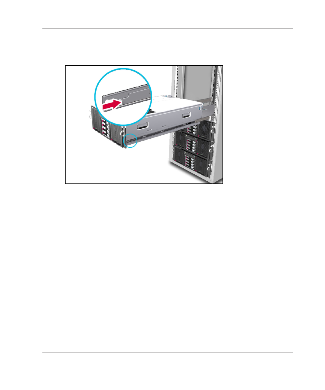
Installing the Server in a Rack
5. Reach around the front of the server to press the rail-release levers at the front of
both server rails, and continue to slide the server into the rack.
Figure 2-9: Sliding the server to the rear of the rack
6. After the server reaches the rear of the rack, slide it back out of the rack until the
rack assembly is fully extended and the rails lock. This action initializes the rail
lock for future use.
7. Press the rack levers at the front of the server rails to release the lock, and slide
the server all the way back into the rack.
HP ProLiant DL740 Server User Guide 2-23
Page 67
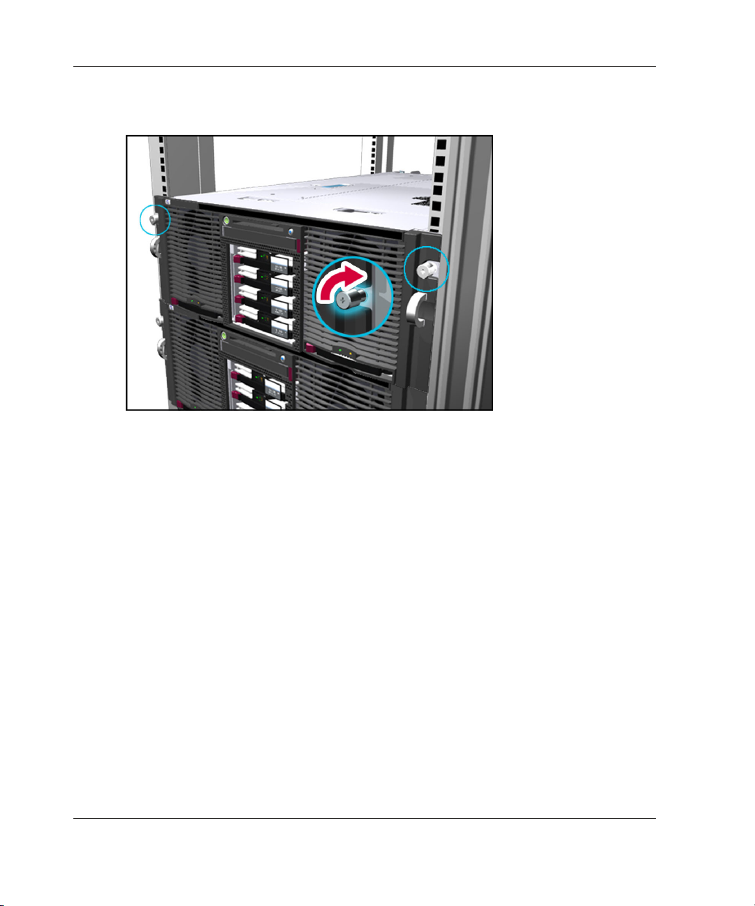
Installing the Server in a Rack
8. Tighten the thumbscrews to secure the server to the rack.
Figure 2-10: Tightening the thumbscrews
Rack Template
The HP ProLiant DL740 server rack template has procedures detailing the rack
installation of the ProLiant DL740 server and how to install the cable management
hardware.
2-24 HP ProLiant DL740 Server User Guide
Page 68

3
Server Access
The ProLiant DL740 server provides easy access to all internal components for
installation and maintenance. This chapter provides details concerning system power
and power supply indicators and removal of the server modules.
HP ProLiant DL740 Server User Guide 3-1
Page 69

Server Access
Server Access Overview
The ProLiant DL740 server chassis facilitates the installation of hardware upgrades
through the use of two removable modules and top access panels. The following table
describes the contents of the modules and how to access the components.
Table 3-1: Module and Bay Components and Access
Module Contents Access Method
PCI Hot Plug expansion slots Open the top access panels.
Configuration switches Open the top access panels.
Host module
Power and media module
Fans 1 and 2 Open the top access panels.
Processor sockets
Memory (DIMMs)
Power supply 1 and 2
Universal media bay
Hot-plug hard drives
Open the top access panels and
remove the processor boards.
Open the top access panels and
remove the memory cartridge.
Access directly at the front
of the server.
Access directly at the front
of the server.
Access directly at the front
of the server.
The following sections provide instructions for removing the power and media
module and host module. For information pertaining to PCI Hot Plug and hot-plug
fan access, refer to Chapter 5.
CAUTION: Do not attempt to remove either of the modules while power is applied to
the system. They are not hot-pluggable. Immediate system shutdown and data loss
will occur.
3-2 HP ProLiant DL740 Server User Guide
Page 70

Unit Identification Switches (Front and Rear)
The ProLiant DL740 server offers Unit Identification (UID) LED switches to aid in
identifying specific servers in a rack environment. Each ProLiant DL740 server has
two unit identification switches, one on the front of the server and one on the back of
the server. When activated from either the front or rear of the server, both Unit
Identification switches illuminate. An LED on the front and rear of the server
provides a visual reference for service personnel. When moving between the front
and rear of a rack filled with ProLiant DL740 servers, you can use the unit
identification switches to quickly identify one or more servers that require service or
maintenance.
Figure 3-1 displays the locations of the Unit Identification LED switches on the front
and rear of the server.
Server Access
Figure 3-1: Locating the UID switch LED
HP ProLiant DL740 Server User Guide 3-3
Page 71

Server Access
Accessing the Host Module
To access the host module to install or replace hot-plug fans or PCI Hot Plug boards:
1. Slide the chassis out of the rack.
2. Unlock the top latch security screw and raise the latch (1), as shown in
Figure 3-2. Hold down the top right access panel and lift the top left access panel
(2). Then lift the top right access panel (3).
Figure 3-2: Opening the top access panels
You can now remove and replace the hot-plug fans and PCI/PCI-X Hot Plug
expansion boards as described in Chapter 5.
3-4 HP ProLiant DL740 Server User Guide
Page 72

Removing the Host Module
Use the procedure in the preceding section, “Accessing the Host Module,” to install
or replace hot-plug fans or PCI/PCI-X Hot Plug expansion boards. To replace or
service non-hot-plug components or address problems in the host module, remove the
module from the chassis.
WARNING: The host module weighs more than 16 kg (35 lb). Remove both
processor boards or all of the memory cartridges before handling the module,
or have at least two people handle the module together.
CAUTION: Do not attempt to remove the host module while power is applied to the
system. The host module is not hot-pluggable. Immediate system shutdown and data
loss will occur.
1. If the computer is on, place the computer in standby mode and disconnect the
power cords. Refer to Chapter 7 for more information.
2. Disconnect all of the cables connected to the I/O expansion boards.
3. Disconnect the cable management harness from the back of the server. Clips at
three points connect it, one at the server (harness clip 1) and both the left and
right cable reels (harness clips 3 and 4). Refer to Chapter 6 for more information.
Server Access
4. Open the top access panels to gain access to the host module and the processor
boards. HP recommends removing the processor boards to lighten the module.
WARNING: To reduce the risk of personal injury from hot surfaces, allow
the internal system components to cool before touching them.
HP ProLiant DL740 Server User Guide 3-5
Page 73
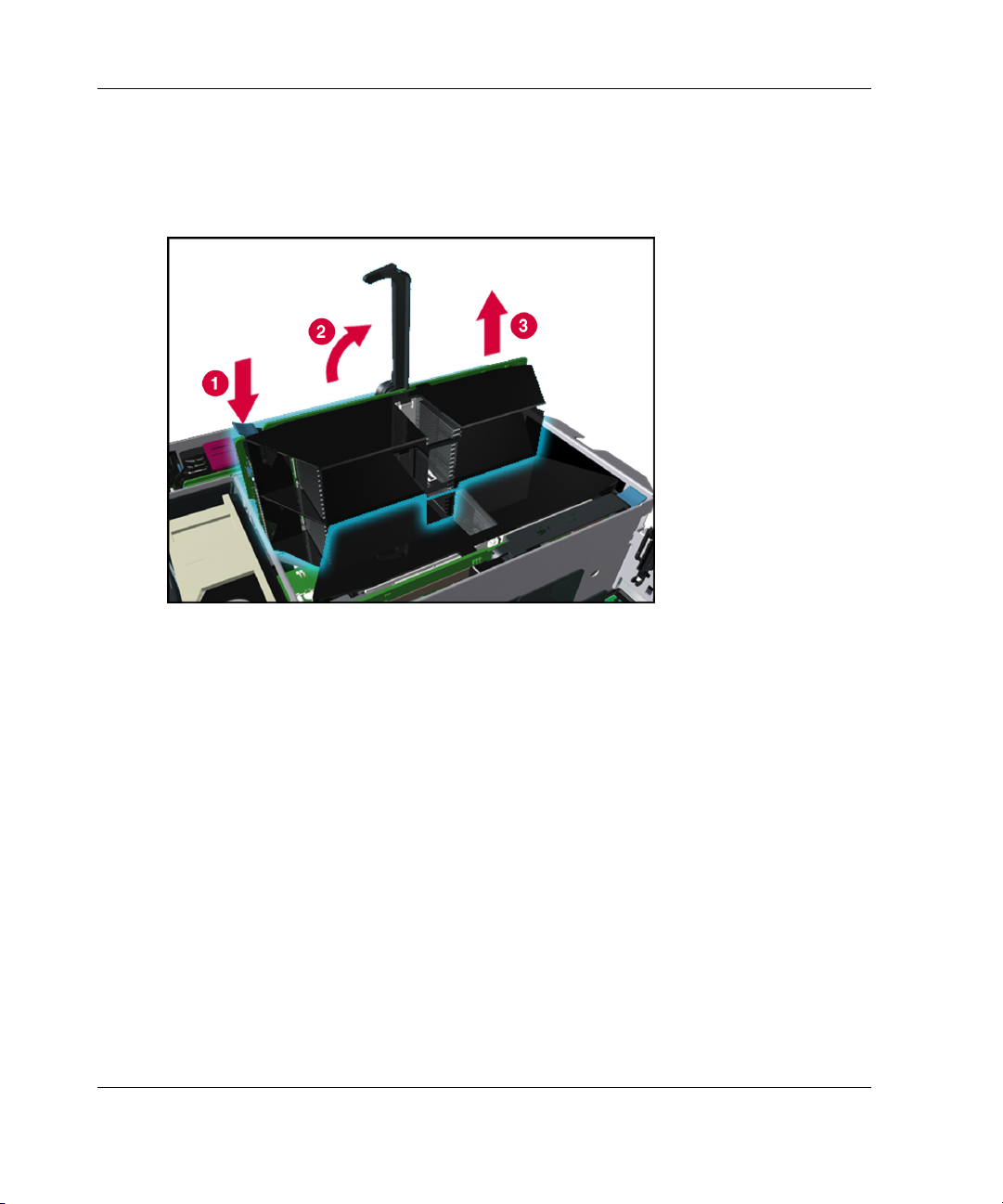
Server Access
5. Push the processor board lever latch down to release the lever (1).
6. Lift the processor board lever up (2) to release the board, and lift the processor
Figure 3-3: Removing the processor board
board out of the module (3).
3-6 HP ProLiant DL740 Server User Guide
Page 74
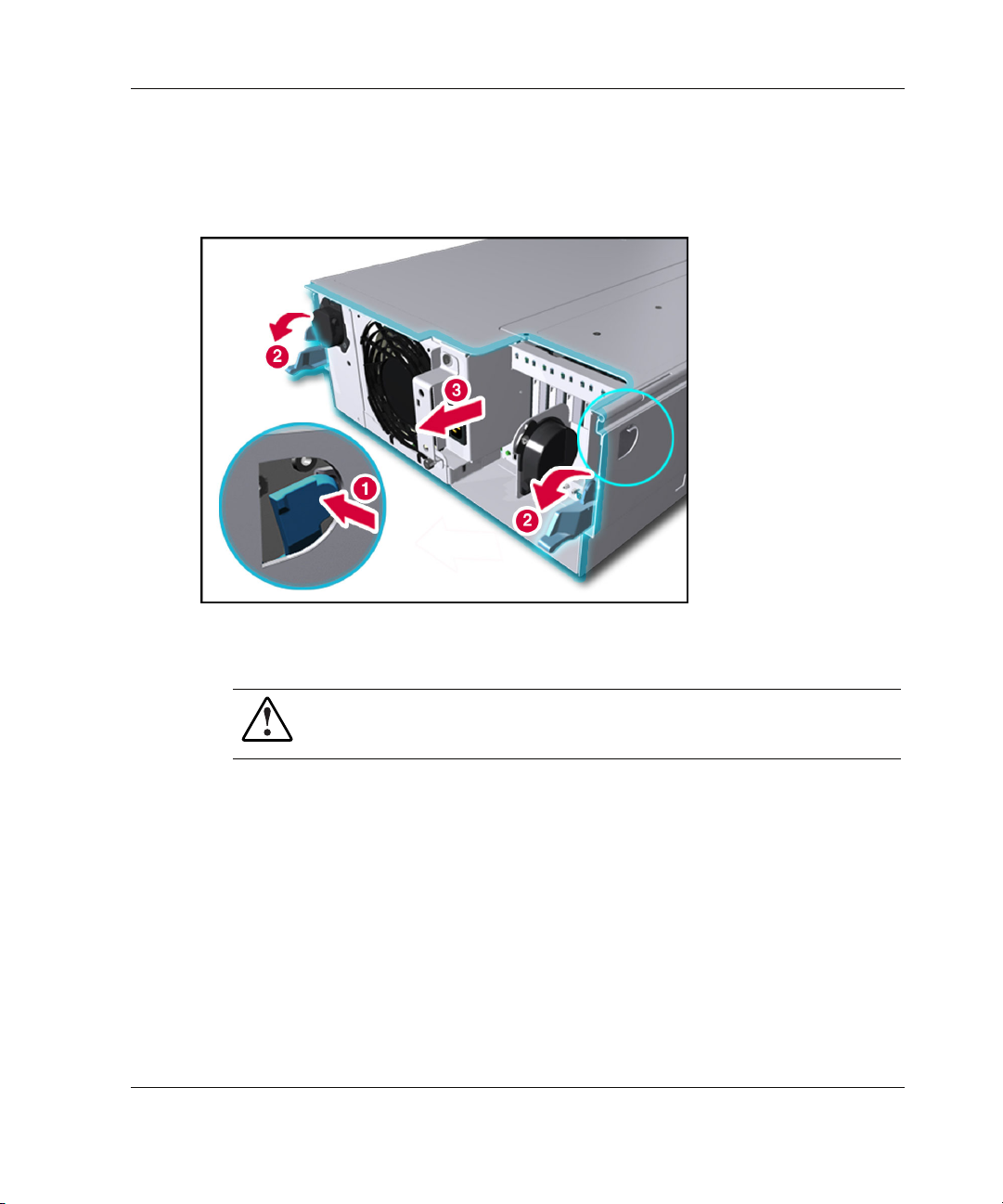
Server Access
7. Push in on the sides of the module release levers (1) on the host module and
rotate the top of the levers downward (2), as shown in Figure 3-4.
8. Pull the host module out of the chassis (3).
Figure 3-4: Releasing the host module
9. Set the host module aside for servicing non-hot-plug components.
WARNING: To reduce the risk of personal injury from hot surfaces, allow
the internal system components to cool before touching them.
10. To view the top panel labels, pull the chassis out of the rack until the chassis
makes contact with the rail stop.
NOTE: The top panel labels provide instructions about installing expansion boards,
setting switches, and installing hot-plug fans, along with information about PCI Hot Plug.
Refer to Chapter 5 for hot-plug procedures.
HP ProLiant DL740 Server User Guide 3-7
Page 75
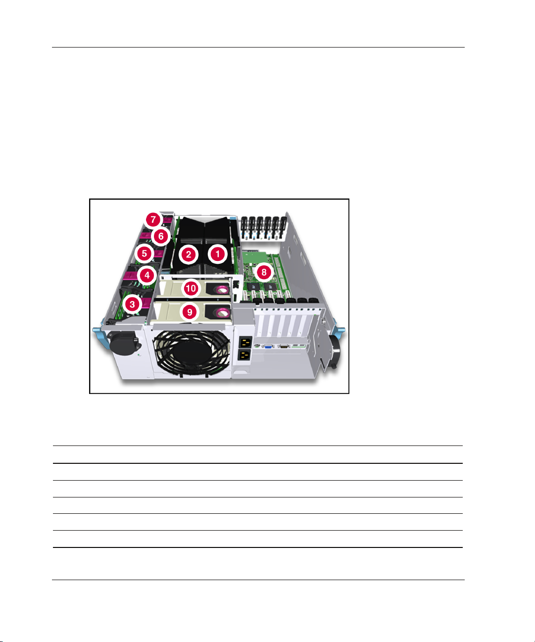
Server Access
11. To reassemble the server, slide the module into the chassis until the module
release levers begin to rotate. Then push the levers shut until they snap into place.
12. Reinstall the cable management harness and I/O cables in the reverse order from
the steps used to remove them.
Host Module Components
Refer to Table 3-2 to identify components in the host module.
Figure 3-5: Host module components
Table 3-2: Host Module Components
Item Component Item Component
1 Processor board 1 6 Memory cartridge 4
2 Processor board 2 7 Memory cartridge 5
3 Memory cartridge 1 8 I/O board
4 Memory cartridge 2 9 System fan 2
5 Memory cartridge 3 10 System fan 1
3-8 HP ProLiant DL740 Server User Guide
Page 76

Server Access
The system board is located in the bottom of the host module. Refer to Table 3-3 to
identify components on the system board.
Figure 3-6: System board components
HP ProLiant DL740 Server User Guide 3-9
Page 77

Server Access
Table 3-3: System Board Components
Item Component
1 Fan 2 connector
2 Fan 1 connector
3 Memory cartridge 1 connector
4 Memory cartridge 2 connector
5 Memory cartridge 3 connector
6 Memory cartridge 4 connector
7 Memory cartridge 5 connector
8 Processor board 2 connector
9 Processor board 1 connector
10 Remote Insight board connector
11 System/midplane board connector
12 I/O board connector
13 System battery
14 iLO diagnostic LEDs
3-10 HP ProLiant DL740 Server User Guide
Page 78

Removing the Power and Media Module
WARNING: The power and media module weighs more than 16 kg (35 lbs) HP
recommends removing both power supplies before handling the module, or
having two people handle the module together.
CAUTION: Do not attempt to remove the power and media module while power is
applied to the system. The module is not hot-pluggable. Immediate system shutdown
and data loss will occur.
To remove the power and media module:
1. If the server is on, place the computer in standby mode and disconnect the power
cords. Refer to Chapter 7.
2. Unseat or remove the host module from the server chassis.
3. Remove the power supplies from the front of the module.
Server Access
HP ProLiant DL740 Server User Guide 3-11
Page 79

Server Access
4. Press the power supply latch to release the power supply handle (1).
5. Rotate the power supply handle outward (2) and slide the power supply out of the
chassis (3), as shown in Figure 3-7. Use both hands when removing the power
supply to support its weight. The power supplies weigh 4 kg (9 lbs) each.
NOTE: When you remove the power supply, a spring-loaded trap door closes to block the
opening. This door preserves the air path required to cool the internal components
of the server.
Figure 3-7: Removing a power supply
3-12 HP ProLiant DL740 Server User Guide
Page 80

Server Access
6. Open the top access panels as shown in Figure 3-2
7. Slide the module release levers (1) on the power and media module, as shown in
Figure 3-8.
8. Pull the power and media module (2) out of the chassis until it encounters the
module stop latches.
Figure 3-8: Releasing the power and media module
HP ProLiant DL740 Server User Guide 3-13
Page 81
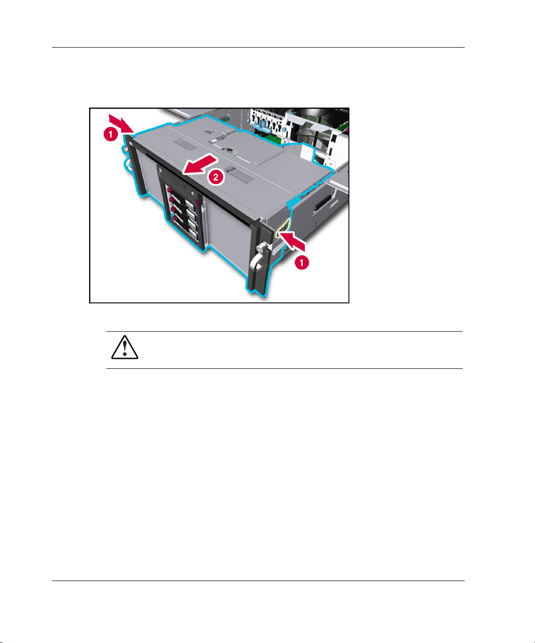
Server Access
9. Press in on the module stop latches (1) and pull the module out of the chassis (2),
Figure 3-9: Removing the power and media module
as shown in Figure 3-9.
WARNING: To reduce the risk of personal injury from hot surfaces, allow
the internal system components to cool before touching them.
10. To reassemble the server, slide the module into the chassis until the levers snap
into place.
3-14 HP ProLiant DL740 Server User Guide
Page 82

Power and Media Module Components
Refer to Table 3-4 to identify components in the power and media module.
Figure 3-10: Power and media module components
Server Access
Table 3-4: Power and Media Module Components
Item Component Item Component
1 Ultra3 hard drive SCSI ID 0 7 Universal media bay, with
DVD/CD-ROM drive
2 Ultra3 hard drive SCSI ID 1 8 1.44 MB diskette drive
3 Ultra3 hard drive SCSI ID 2 9 Unit identification switch LED
4 Ultra3 hard drive SCSI ID 3 10 Universal media bay eject button
5 Power supply 1 11 Power supply 2
6 Power On/Standby switch
HP ProLiant DL740 Server User Guide 3-15
Page 83

4
Installing Hardware Options, Non-Hot-Plug
The following instructions are provided as an overview for installing hardware option
upgrades that require the system power to be off. HP recommends that you use the
documentation provided with the hardware option for complete installation
instructions. You can also refer to the HP ProLiant DL740 Server Supplemental
Setup Guide included in the shipping box or to the labels attached to the top panel of
the server.
WARNING: To reduce the risk of personal injury or damage to the equipment,
heed all warnings and cautions throughout the installation instructions.
WARNING: To reduce the risk of personal injury or damage to the equipment,
the installation of options other than hot-plug power supplies and hot-plug
hard drives should be performed only by individuals who are qualified in
servicing computer equipment and are trained to deal with products capable of
producing hazardous energy levels.
WARNING: To reduce the risk of personal injury from hazardous energy or
damage to the equipment when working on energized servers:
• Remove all watches, rings, and any other loose-fitting jewelry.
• Avoid the use of conductive tools that could bridge live parts.
CAUTION: Electrostatic discharge can damage electronic components. Be sure that
you are properly grounded before beginning any installation procedure. Refer to
Appendix B for more information.
HP ProLiant DL740 Server User Guide 4-1
Page 84

Installing Hardware Options, Non-Hot-Plug
Intel Xeon Processor MP
The ProLiant DL740 server supports either four or eight processors.
• All processors installed on a processor board must be the same speed, cache size,
and stepping. Stepping refers to the processor revision.
• If two processor boards are installed, all processors in both processor boards
must be the same speed, cache size, and stepping.
• Processor 1 must always be installed to properly terminate the processor bus.
4-2 HP ProLiant DL740 Server User Guide
Page 85

Figure 4-1: Processor board layout
Item Description
1 Intel Xeon processor MP in socket 1
2 Intel Xeon processor MP in socket 2
3 Intel Xeon processor MP in socket 3
4 Intel Xeon processor MP in socket 4
Installing Hardware Options, Non-Hot-Plug
HP ProLiant DL740 Server User Guide 4-3
Page 86

Installing Hardware Options, Non-Hot-Plug
Installing a Processor Board
The ProLiant DL740 server is capable of supporting up to eight Intel Xeon
processors MP and is shipped with four processors installed.
The ProLiant DL740 server has space for two processor boards in the host module.
Figure 4-2: Processor board locations
Item Description
1 Processor board in processor board slot 1
2 Processor board in processor board slot 2
4-4 HP ProLiant DL740 Server User Guide
Page 87

Installing Hardware Options, Non-Hot-Plug
To install a processor board option kit (with four processors) into the host module:
1. Back up all data on the server.
2. Shut down the operating system as directed by your operating system
instructions.
3. If the server was not powered down in the previous step, power down the server
(refer to Chapter 7).
4. Disconnect the power cords from the server.
5. Open the top access panels to access the host module (refer to Chapter 3).
WARNING: To reduce the risk of personal injury from hot surfaces, allow
the internal system components to cool before touching them.
6. Remove the processor board air baffle by pressing in the release tab (1) while
pulling the air baffle up (2).
Figure 4-3: Removing the processor board air baffle
HP ProLiant DL740 Server User Guide 4-5
Page 88

Installing Hardware Options, Non-Hot-Plug
7. Insert the processor board into processor board slot 2 of the module (1).
8. Push down the processor board lever until it is secured by the lever latch (2).
Figure 4-4: Installing the processor board
9. Close the top access panels.
NOTE: Processor board 2 need not be installed for the server to run. If only one
processor board is installed, be sure the processor board air baffle is in place to provide
optimal airflow.
10. Connect all power cords and power up the server. If the system does not power
up, verify that the system interconnect LEDs are normal. Refer to the section,
“System Interconnect Status Indicators” in Chapter 7.
11. Be sure that the processor has been installed correctly. Check the processor
speed, cache size, and socket location by reviewing the POST messages on the
system console.
4-6 HP ProLiant DL740 Server User Guide
Page 89
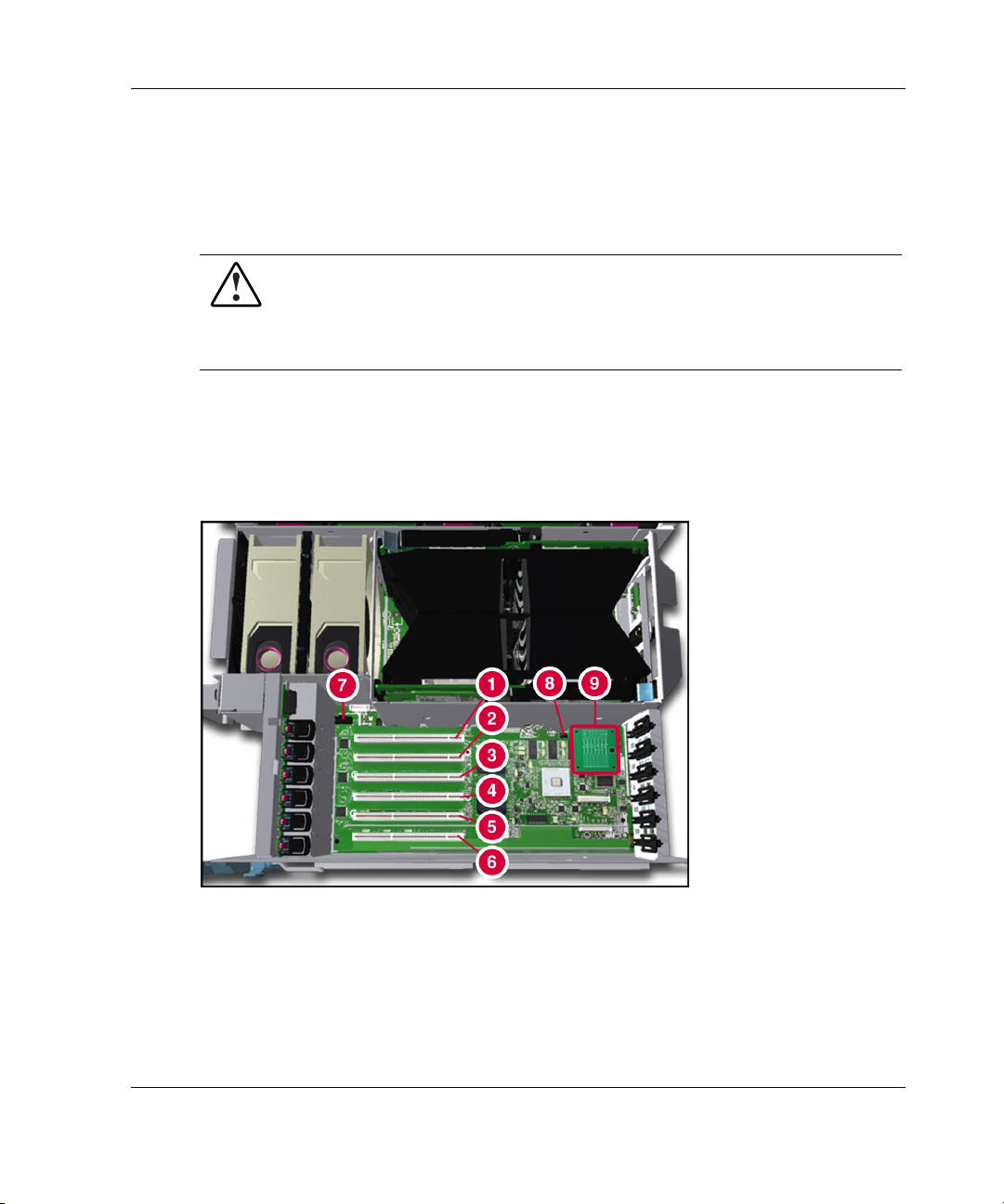
Non-Hot-Plug I/O Expansion
The PCI-X slots of the ProLiant DL740 server I/O board support a variety of
industry-standard expansion boards.
WARNING: To reduce the risk of personal injury from hazardous energy or
damage to the equipment when working on energized servers:
• Remove all watches, rings, and any other loose-fitting jewelry.
• Avoid the use of conductive tools that could bridge live parts.
Locating the I/O Expansion Slots
The I/O expansion slots are located in the host module and are accessed by sliding
the server out of the rack and opening the top access panel, as described in Chapter 3.
Installing Hardware Options, Non-Hot-Plug
Figure 4-5: Locating the I/O expansion slots
HP ProLiant DL740 Server User Guide 4-7
Page 90

Installing Hardware Options, Non-Hot-Plug
Table 4-1: I/O Expansion Slots
Item Description
Slots 1–2 PCI bus 7—Supports 64-bit PCI-X expansion boards at 100 MHz;
it is keyed for 3.3v signaling.
Slots 3–4 PCI bus 11—Supports 64-bit PCI-X expansion boards at 100 MHz;
it is keyed for 3.3v signaling.
Slots 5–6 PCI bus 3—Supports 64-bit PCI-X expansion boards at 100 MHz;
it is keyed for 3.3v signaling.
7 PCI-X hot-plug switchboard cable connector
8 I/O board switch bank (SW7)
9 Array enabler board
Note: The operating system detects PCI devices in the following slot order: 5-6-1-2-3-4.
The I/O expansion slots are distributed among three separate PCI-X buses.
Adding Non-Hot-Plug Expansion Boards
You can use non-hot-plug expansion boards in the ProLiant DL740 server, but you
must install them according to the following procedure. To prepare the server:
1. If this is the first time you have powered up the server, skip to step 4. If you have
previously powered up the server, back up the server data.
2. Shut down the operating system as directed in your operating system instructions.
3. Power down the server (refer to Chapter 7).
4. Disconnect the power cords from the server.
5. Slide the server out of the rack.
6. Open the top access panel, as shown in Chapter 3.
4-8 HP ProLiant DL740 Server User Guide
Page 91

Installing Hardware Options, Non-Hot-Plug
To add an expansion board:
1. Press on the top (1) of the appropriate expansion slot release lever and open the
lever toward the rear (2) of the expansion slot.
2. Remove the expansion slot cover (3).
Figure 4-6: Preparing the expansion slot for installation
HP ProLiant DL740 Server User Guide 4-9
Page 92

Installing Hardware Options, Non-Hot-Plug
3. Insert the PCI/PCI-X expansion board into the appropriate expansion slot (1),
pushing firmly until the board is securely seated.
4. Close the expansion slot release lever from the rear of the unit to secure the board
(2). Be sure that the lever latches into the closed position.
Figure 4-7: Inserting the PCI/PCI-X expansion board
5. Connect the expansion board I/O cable as appropriate.
4-10 HP ProLiant DL740 Server User Guide
Page 93

Installing Hardware Options, Non-Hot-Plug
HP has designed a self-latching slot-keeper feature to accommodate
full-length expansion boards.
Be sure that the V-shaped slot-keeper tabs on the plastic expansion board guide
are positioned over the forward end of the expansion board. Using the slot
keepers is especially important when expansion boards are added or when the
server is moved.
Figure 4-8: Full-length self-latching slot-keeper feature
6. Close the top access panel, and slide the server into the rack.
7. Connect all power cords and power up the server (refer to Chapter 7).
8. If necessary, run the ROM-Based Setup Utility, as described in Chapter 8.
NOTE: For a list of supported I/O expansion boards, refer to the HP QuickSpecs for the
ProLiant DL740 servers at www.hp.com/products/servers/platforms.
NOTE: Each PCI-X bus is automatically configured to run in the most advanced mode
(PCI-X or PCI) and the highest frequency supported by all expansion boards installed in the
slots on the bus.
HP ProLiant DL740 Server User Guide 4-11
Page 94
Installing Hardware Options, Non-Hot-Plug
Installing the Integrated Array Bypass
Use the Integrated Array Bypass kit to bypass the Smart Array 5i Controller and use
an optional controller.
The Smart Array 5i Controller is routed to the internal drives through the Array
Enabler board in the host module.
The Integrated Array Bypass kit allows you to replace the Array Enabler board with a
connector and cable that you can connect to an optional controller board.
WARNING: To reduce the risk of personal injury from hot surfaces, allow the
internal system components to cool before touching them.
CAUTION: Back up the data each time that you move drive arrays or change the
configuration.
To install the Integrated Array Bypass:
1. If you have not powered up your server for the first time, skip to step 4. If you
have powered up your server, back up your server data.
2. Shut down the operating system as directed in your operating system instructions.
3. Power down the server (refer to Chapter 7).
4. Disconnect the power cords from the server.
5. Slide the server out of the rack.
4-12 HP ProLiant DL740 Server User Guide
Page 95

Installing Hardware Options, Non-Hot-Plug
6. Open the top left access panel, as shown in Chapter 3.
7. Slide the retaining clip (1) and remove the Array Enabler board (2) from the
server, as shown in Figure 4-9.
NOTE: Retain the Array Enabler board for future use.
Figure 4-9: Removing the Array Enabler board
HP ProLiant DL740 Server User Guide 4-13
Page 96

Installing Hardware Options, Non-Hot-Plug
8. Install the Integrated Array Bypass assembly, as shown in Figure 4-10.
IMPORTANT: The Integrated Array Bypass assembly cable comes as a standard
accessory in the hardware option kit.
Figure 4-10: Installing the Integrated Array
Bypass assembly
4-14 HP ProLiant DL740 Server User Guide
Page 97

Installing Hardware Options, Non-Hot-Plug
9. Press on the top (1) of the appropriate expansion slot release lever and open the
lever toward the rear (2) of the expansion slot.
10. Remove the expansion slot cover (3).
Figure 4-11: Preparing the expansion slot for
installation
HP ProLiant DL740 Server User Guide 4-15
Page 98

Installing Hardware Options, Non-Hot-Plug
11. Install the optional array controller board (1) as shown in Figure 4-12 and close
the expansion slot release lever (2). Close the full-length self-latching slot-keeper
feature.
IMPORTANT: HP recommends installing the optional array controller board
into PCI-X slot 6.
Figure 4-12: Installing the array controller board
4-16 HP ProLiant DL740 Server User Guide
Page 99

Installing Hardware Options, Non-Hot-Plug
12. Connect the Integrated Array Bypass assembly cable to the optional array
controller board, as shown in Figure 4-13.
Figure 4-13: Connecting the Integrated Array Bypass
assembly cable
NOTE: The actual appearance and routing of the cable in the preceding figures depend
on which slot the optional array controller board occupies.
13. Close the top left access panel and slide the server into the rack.
14. Connect all power cords and power up the server (refer to Chapter 7).
15. Run the ROM-Based Setup Utility, as described in Chapter 8.
16. Configure the new controller with the Option ROM for Configuration Arrays or
the Array Configuration Utility, as described in Chapter 8.
NOTE: Refer to the documentation included with the optional controller for more
information about SCSI setup and configuration.
HP ProLiant DL740 Server User Guide 4-17
Page 100
5
Installing Hardware Options, Hot-Plug
The following instructions are provided as an overview for installing hardware option
upgrades that are hot-pluggable. HP recommends that you use the documentation
provided with the hardware option for complete installation instructions. You can
also refer to the HP ProLiant DL740 Server Supplemental Setup Guide included in
the shipping box or to the labels attached to the top panel of the server.
WARNING: To reduce the risk of personal injury or damage to the equipment,
heed all warnings and cautions throughout the installation instructions.
WARNING: To reduce the risk of personal injury or damage to the equipment,
the installation of options other than hot-plug power supplies and hot-plug
hard drives should be performed only by individuals who are qualified in
servicing computer equipment and are trained to deal with products capable of
producing hazardous energy levels.
WARNING: To reduce the risk of personal injury from hazardous energy or
damage to the equipment when working on energized servers:
• Remove all watches, rings, and any other loose-fitting jewelry.
• Avoid the use of conductive tools that could bridge live parts.
CAUTION: Electrostatic discharge can damage electronic components. Be sure that
you are properly grounded before beginning any installation procedure. Refer to
Appendix B for more information.
HP ProLiant DL740 Server User Guide 5-1
 Loading...