

HP ProLiant DL585 G7 User Manual

HP ProLiant DL585 G7 Server
Part Number: 617692-004
User Guide
Abstract
This document is for the person who installs, administers, and troubleshoots servers and storage systems. HP assumes you are qualified in the
servicing of computer equipment and trained in recognizing hazards in products with hazardous energy levels.
October 2012
Edition: 4

© Copyright 2010, 2012 Hewlett-Packard Development Company, L.P.
The information contained herein is subject to change without notice. The only warranties for HP products and services are set forth in the express
warranty statements accompanying such products and services. Nothing herein should be construed as constituting an additional warranty. HP shall
not be liable for technical or editorial errors or omissions contained herein.
Microsoft® and Windows® are U.S. registered trademarks of Microsoft Corporation.
AMD is a trademark of Advanced Micro Devices, Inc.
Bluetooth® is a trademark owned by its proprietor and used by Hewlett-Packard Company under license.

Contents
Component identification ............................................................................................................... 7
Front panel components ............................................................................................................................. 7
Front panel LEDs and buttons ...................................................................................................................... 8
Systems Insight Display .............................................................................................................................. 9
Rear panel components ............................................................................................................................ 10
Rear panel LEDs and buttons ..................................................................................................................... 11
Power supply LED .................................................................................................................................... 12
System board components ........................................................................................................................ 13
System maintenance switch ............................................................................................................. 14
SPI board components ............................................................................................................................. 15
I/O expansion board components ............................................................................................................. 16
DIMM slot locations ................................................................................................................................. 17
Device numbers ...................................................................................................................................... 18
SAS hard drive LEDs ...................................................................................................................... 19
SAS hard drive LED combinations .................................................................................................... 19
Battery pack LEDs .................................................................................................................................... 20
FBWC module LEDs ................................................................................................................................. 22
Fan locations .......................................................................................................................................... 23
Power supply backplane components ......................................................................................................... 23
Operations ................................................................................................................................. 25
Power up the server ................................................................................................................................. 25
Power down the server ............................................................................................................................. 25
Extend the server from the rack ................................................................................................................. 25
Remove the access panel.......................................................................................................................... 26
Install the access panel............................................................................................................................. 27
Remove the processor memory drawer ....................................................................................................... 27
Access the Systems Insight Display ............................................................................................................. 28
Remove the SPI board .............................................................................................................................. 28
Setup ......................................................................................................................................... 30
Optional installation services .................................................................................................................... 30
Rack planning resources........................................................................................................................... 30
Optimum environment .............................................................................................................................. 30
Space and airflow requirements ...................................................................................................... 31
Temperature requirements ............................................................................................................... 31
Power requirements ....................................................................................................................... 32
Electrical grounding requirements .................................................................................................... 32
Rack warnings ........................................................................................................................................ 32
Identifying the contents of the server shipping carton .................................................................................... 33
Installing hardware options ....................................................................................................................... 33
Installing the server into the rack ................................................................................................................ 33
Powering up and configuring the server ..................................................................................................... 33
Installing the operating system................................................................................................................... 34
Registering the server ............................................................................................................................... 34
Hardware options installation ....................................................................................................... 35
Contents 3

Introduction ............................................................................................................................................ 35
Secondary processor memory board option ................................................................................................ 35
Processor options .................................................................................................................................... 37
Installing a processor option ........................................................................................................... 37
Memory configurations ............................................................................................................................ 43
Population order ............................................................................................................................ 43
Population rules ............................................................................................................................. 44
Population guidelines ..................................................................................................................... 44
Online Spare memory population guidelines ..................................................................................... 44
Memory bus speed ........................................................................................................................ 45
Single-, dual-, and quad-rank DIMMs ............................................................................................... 46
DIMM identification ....................................................................................................................... 46
Advanced ECC memory ................................................................................................................. 47
Installing DIMMs on the primary processor memory board .................................................................. 47
Installing DIMMs on the secondary processor memory board .............................................................. 49
Hot-plug hard drive option ........................................................................................................................ 50
Redundant hot-plug power supply option .................................................................................................... 52
Internal solid state drive expansion bay option ............................................................................................ 53
Expansion board options .......................................................................................................................... 54
Installing an expansion board ......................................................................................................... 54
Securing an expansion board for shipping ....................................................................................... 55
Installing the PCI Express I/O expansion board ................................................................................. 57
Installing the PCI-X/PCI Express I/O expansion board ........................................................................ 59
HP NC524SFP Dual Port 10GbE Module option ......................................................................................... 61
Battery-backed write cache module ............................................................................................................ 63
FBWC module and capacitor pack option .................................................................................................. 65
HP Trusted Platform Module option ............................................................................................................ 67
Retaining the recovery key/password .............................................................................................. 68
Installing the Trusted Platform Module board ..................................................................................... 68
Enabling the Trusted Platform Module ............................................................................................... 70
Cabling ..................................................................................................................................... 71
DVD-ROM drive cabling ........................................................................................................................... 71
Server software and configuration utilities ...................................................................................... 72
Configuration tools .................................................................................................................................. 72
SmartStart software ........................................................................................................................ 72
HP ROM-Based Setup Utility ............................................................................................................ 72
Array Configuration Utility .............................................................................................................. 75
Option ROM Configuration for Arrays ............................................................................................. 75
Re-entering the server serial number and product ID ........................................................................... 76
Management tools ................................................................................................................................... 76
Automatic Server Recovery ............................................................................................................. 76
ROMPaq utility .............................................................................................................................. 77
Integrated Lights-Out 3 technology ................................................................................................... 77
Erase Utility .................................................................................................................................. 77
Redundant ROM support ................................................................................................................ 78
USB support .................................................................................................................................. 78
Diagnostic tools ...................................................................................................................................... 79
HP Insight Diagnostics .................................................................................................................... 79
HP Insight Diagnostics survey functionality ........................................................................................ 79
Integrated Management Log ........................................................................................................... 79
Remote support and analysis tools ............................................................................................................. 80
HP Insight Remote Support software ................................................................................................. 80
Contents 4

Keeping the system current ....................................................................................................................... 80
Drivers ......................................................................................................................................... 80
Version control .............................................................................................................................. 81
ProLiant Support Packs ................................................................................................................... 81
Operating System Version Support .................................................................................................. 81
Firmware ...................................................................................................................................... 81
HP Smart Update Manager ............................................................................................................. 81
Change control and proactive notification ........................................................................................ 82
Care Pack .................................................................................................................................... 82
Troubleshooting .......................................................................................................................... 83
Troubleshooting resources ........................................................................................................................ 83
Pre-diagnostic steps ................................................................................................................................. 83
Important safety information ............................................................................................................ 83
Symptom information ..................................................................................................................... 85
Prepare the server for diagnosis ...................................................................................................... 85
Loose connections ................................................................................................................................... 86
Service notifications ................................................................................................................................. 87
Troubleshooting flowcharts ....................................................................................................................... 87
Start diagnosis flowchart ................................................................................................................ 87
General diagnosis flowchart ........................................................................................................... 88
Server power-on problems flowchart ................................................................................................ 90
POST problems flowchart ............................................................................................................... 93
OS boot problems flowchart ........................................................................................................... 95
Server fault indications flowchart ..................................................................................................... 96
POST error messages and beep codes ....................................................................................................... 98
Battery replacement .................................................................................................................. 100
Regulatory compliance notices ................................................................................................... 101
Regulatory compliance identification numbers ........................................................................................... 101
Federal Communications Commission notice ............................................................................................. 101
FCC rating label .......................................................................................................................... 101
FCC Notice, Class A Equipment .................................................................................................... 101
FCC Notice, Class B Equipment .................................................................................................... 101
Declaration of conformity for products marked with the FCC logo, United States only ..................................... 102
Modifications ........................................................................................................................................ 102
Cables ................................................................................................................................................. 102
Canadian notice (Avis Canadien) ............................................................................................................ 102
European Union regulatory notice ........................................................................................................... 103
Disposal of waste equipment by users in private households in the European Union ....................................... 103
Japanese notice .................................................................................................................................... 104
BSMI notice .......................................................................................................................................... 104
Korean notice ....................................................................................................................................... 104
Chinese notice ...................................................................................................................................... 105
Laser compliance .................................................................................................................................. 105
Battery replacement notice ...................................................................................................................... 105
Taiwan battery recycling notice ............................................................................................................... 106
Power cord statement for Japan ............................................................................................................... 106
Acoustics statement for Germany (Geräuschemission) ................................................................................ 106
Wireless devices ................................................................................................................................... 106
Brazilian notices .......................................................................................................................... 107
Canadian notices ........................................................................................................................ 107
Japanese notices ......................................................................................................................... 107
Contents 5

Taiwan notices ............................................................................................................................ 108
Electrostatic discharge ............................................................................................................... 109
Preventing electrostatic discharge ............................................................................................................ 109
Grounding methods to prevent electrostatic discharge ................................................................................ 109
Specifications ........................................................................................................................... 110
Environmental specifications ................................................................................................................... 110
Server specifications .............................................................................................................................. 110
Support and other resources ...................................................................................................... 111
Before you contact HP ............................................................................................................................ 111
HP contact information ........................................................................................................................... 111
Customer Self Repair ............................................................................................................................. 111
Acronyms and abbreviations ...................................................................................................... 119
Documentation feedback ........................................................................................................... 122
Index ....................................................................................................................................... 123
Contents 6
Component identification
Optical drive
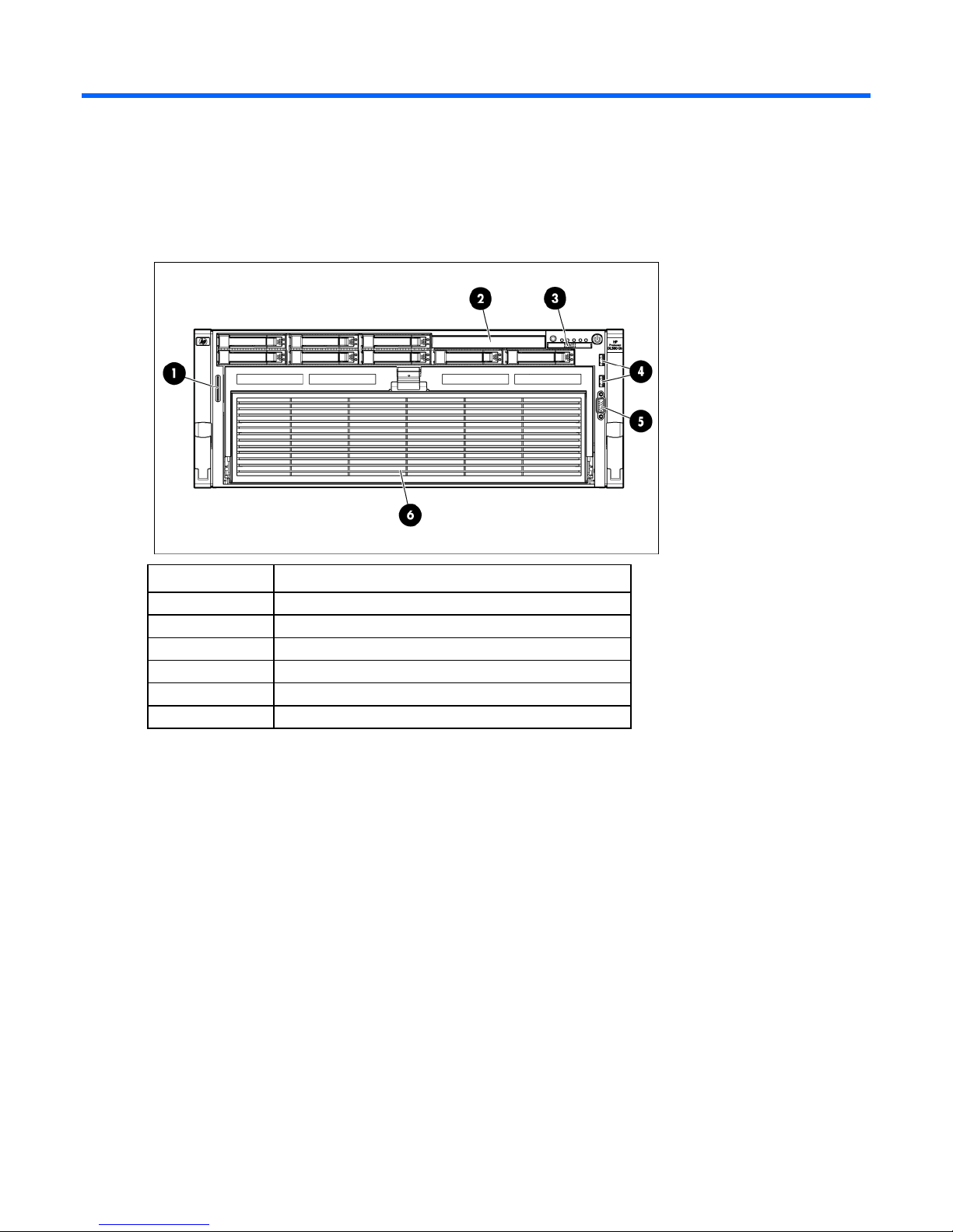
Front panel components
Item Description
1
2
3
4
5
6
Serial and PID tag
Systems Insight Display
USB connectors (2)
Video connector
Processor memory drawer
Component identification 7

Front panel LEDs and buttons
Item Description Status
1
2
3
4
5
6
7
UID button and LED Blue—Activated
Blue (flashing)—Server being managed remotely
Off—Deactivated
Health LED Green—Normal (system on)
Amber (flashing)—Internal system health degraded
Red (flashing)—Internal system health critical
Off—Normal (system off)
NIC 1 LED Green—Linked to network
Green (flashing)—Linked with activity on the network
Off—No network connection
NIC 2 LED Green—Linked to network
Green (flashing)—Linked with activity on the network
Off—No network connection
NIC 3 LED Green—Linked to network
Green (flashing)—Linked with activity on the network
Off—No network connection
NIC 4 LED Green—Linked to network
Green (flashing)—Linked with activity on the network
Off—No network connection
Power on/Standby button and
LED
Amber—System has AC power and is in standby mode.
Green—System has AC power and is powered on.
Off—System has no AC power.
Component identification 8
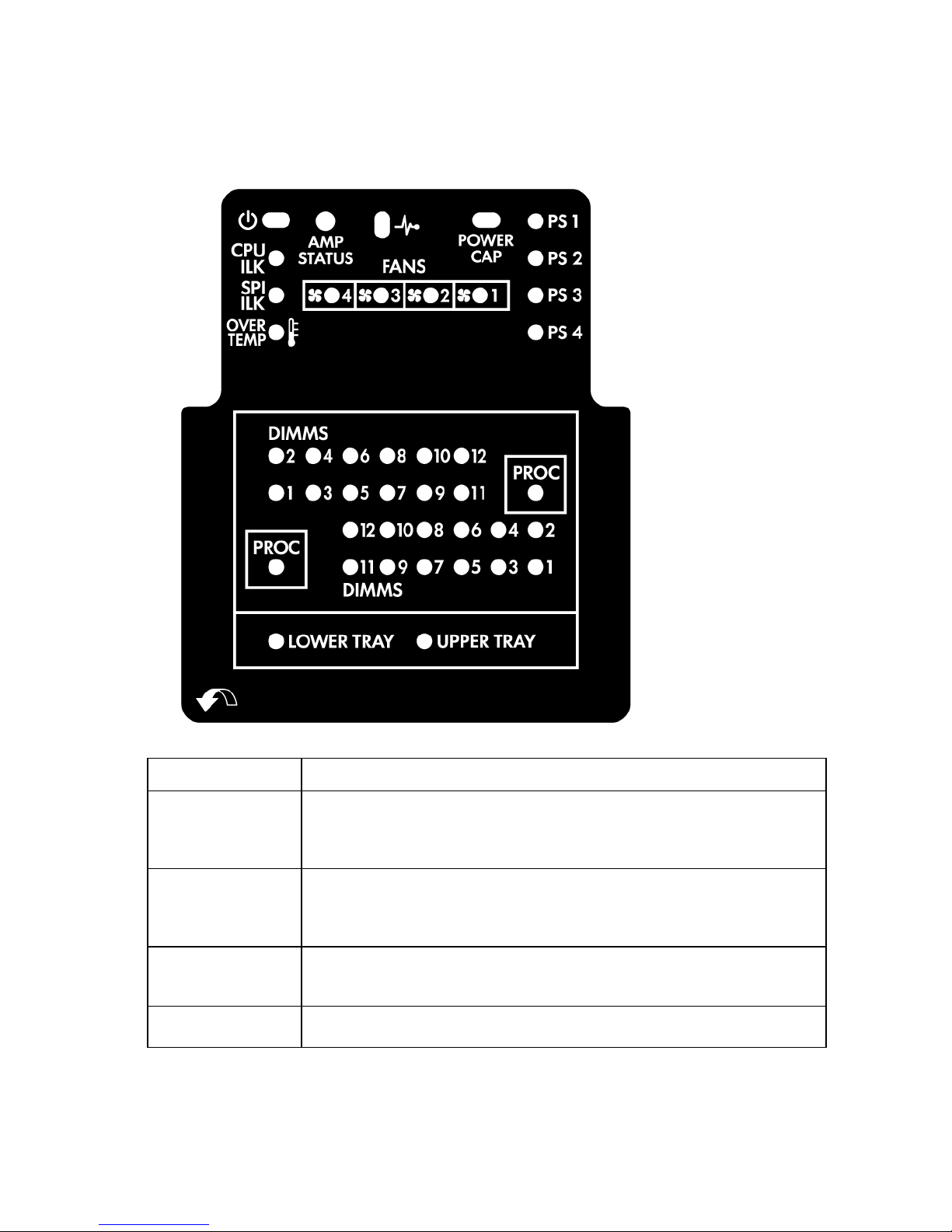
Systems Insight Display
The Systems Insight Display LEDs represent the server and component layout.
LED Description
AMP status
Health
Power cap
All other LEDs
Off—No protection
Green—Protection enabled
Amber—Memory failure occurred
Amber (flashing)—Memory configuration error
Green—Normal (system on)
Amber (flashing)—Internal system health degraded
Red (flashing)—Internal system health critical
Off—Normal (system off)
Green—System on or requesting poweron
Amber (flashing)—Poweron denied
Off—Standby
Off—Normal
Amber—Failed or missing component
Component identification 9
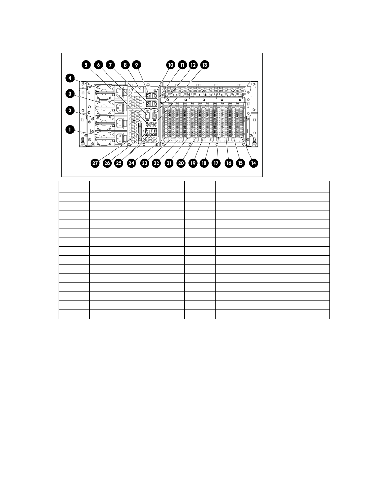
Rear panel components
Power supply bay 2
17
Expansion slot 4 (optional)
Item Description Item Description
1
2
3
4
5
6
7
8
9
10
11
12
13
14
*Applicable only on the NC375i SPI board
For optional configuration of slots 1–6, see "I/O expansion board components (on page 16)."
Power supply bay 4 (optional) 15 Expansion slot 2 (optional)
Power supply bay 3 (optional) 16 Expansion slot 3 (optional)
Power supply bay 1 18 Expansion slot 5 (optional)
Mouse connector 19 Expansion slot 6 (optional)
Serial connector 20 PCIe2 x8 expansion slot 7
NIC 2 connector 21 PCIe2 x8 expansion slot 8
10Gb NIC adapter blank* 22 PCIe2 x16 expansion slot 9
NIC 4 connector 23 PCIe2 x8 expansion slot 10
NIC 3 connector 24 PCIe2 x16 expansion slot 11
NIC 1 connector 25 USB connectors (2)
Video connector 26 iLO 3 connector
Keyboard connector 27 T-10/T-15 Torx screwdriver
Expansion slot 1 (optional) — —
Component identification 10
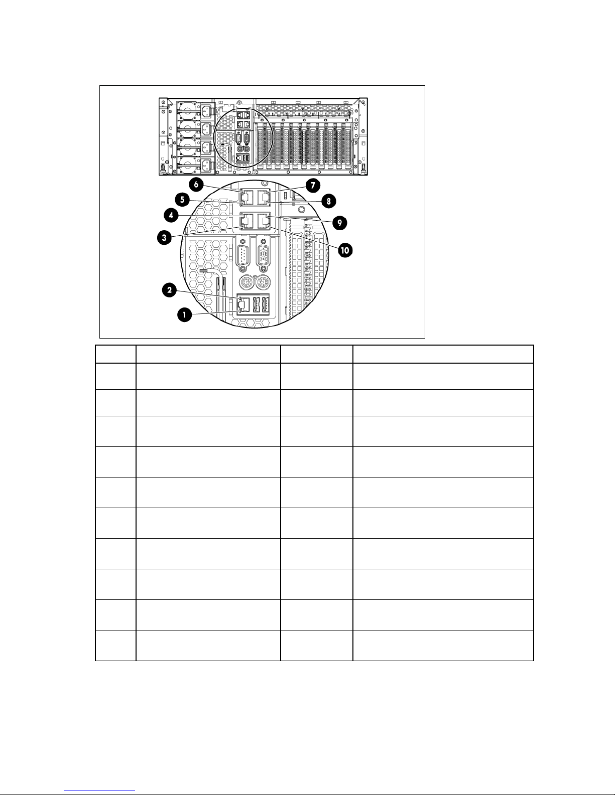
Rear panel LEDs and buttons
Item Description LED color Status
1
2
3
4
5
6
7
8
9
iLO 3 NIC Activity LED Green On or flashing—Network activity
Off—No network activity
iLO 3 NIC Link LED Green On—Linked to network
Off—Not linked to network
NIC 2 Activity LED Green On or flashing—Network activity
Off—No network activity
NIC 2 Link LED Green On—Linked to network
Off—Not linked to network
NIC 4 Activity LED Green On or flashing—Network activity
Off—No network activity
NIC 4 Link LED Green On—Linked to network
Off—Not linked to network
NIC 3 Link LED Green On—Linked to network
Off—Not linked to network
NIC 3 Activity LED Green On or flashing—Network activity
Off—No network activity
NIC 1 Link LED Green On—Linked to network
Off—Not linked to network
10
NIC 1 Activity LED Green On or flashing—Network activity
Off—No network activity
Component identification 11
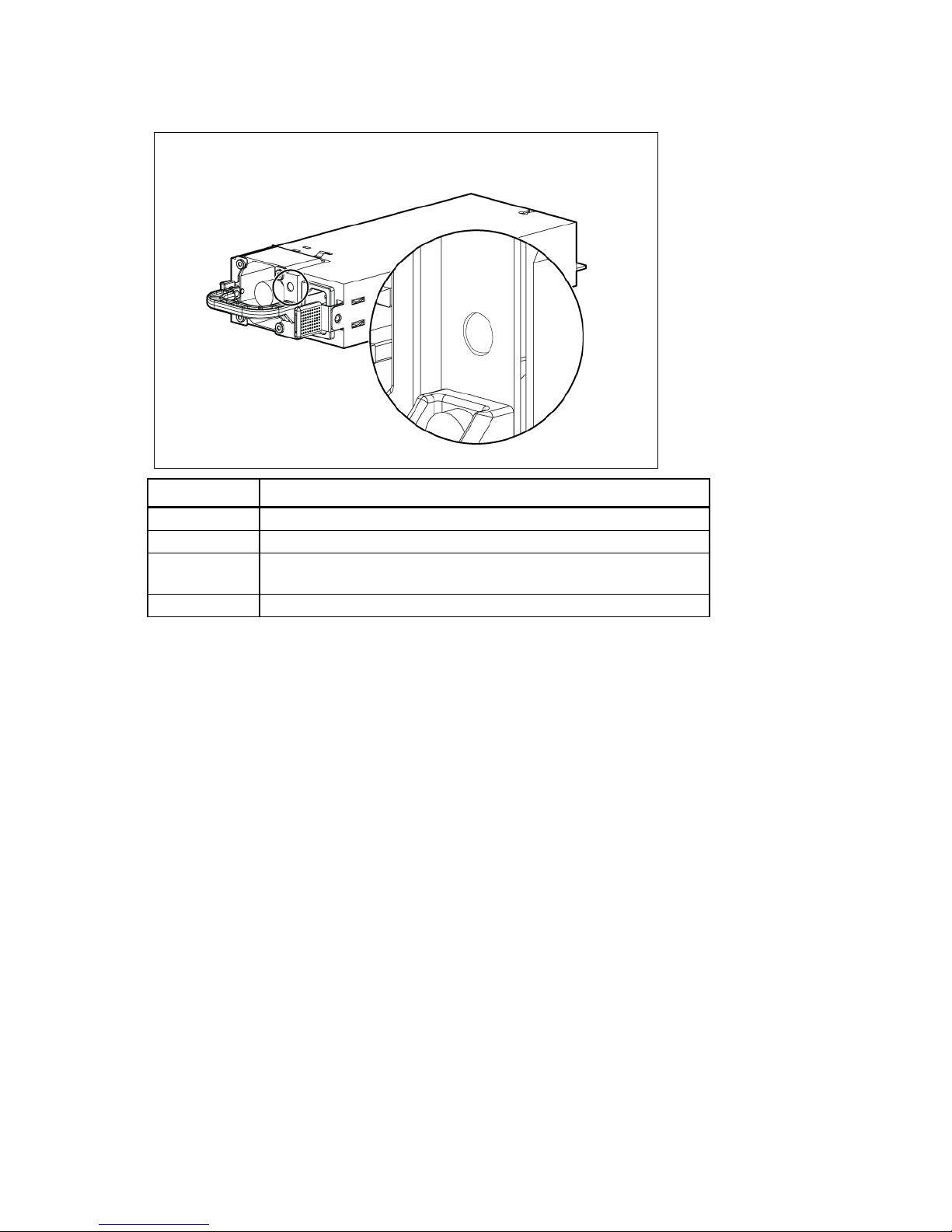
Power supply LED
Power LED Status
Off
Green
Green
Off
No AC power to power supply units
AC is present. Standby output is on, output is disabled.
AC is present. Standby output is on, power supply DC output is on and
OK.
Power supply failure (includes overvoltage and overtemperature)
Component identification 12
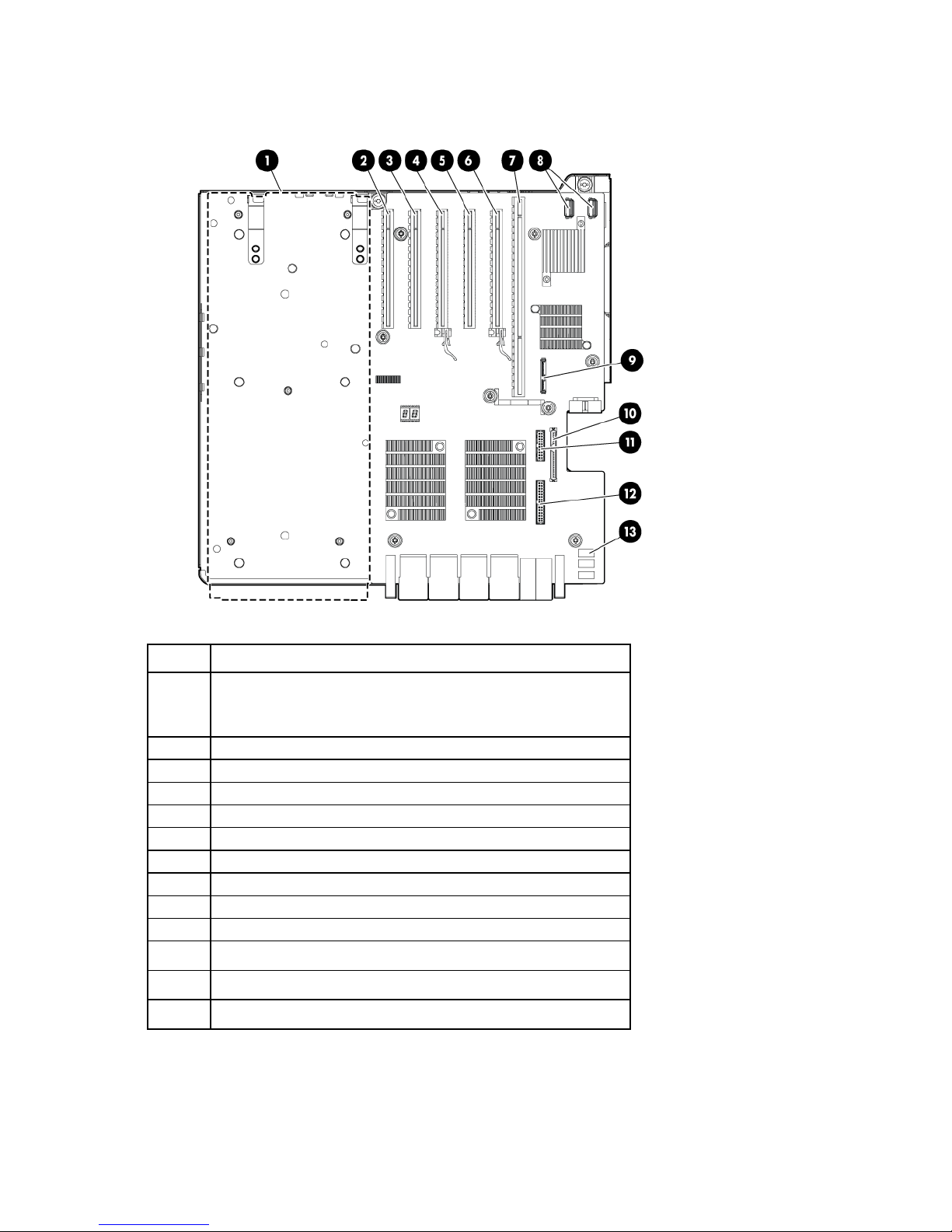
System board components
•
•
Item Description
1
Optional I/O expansion board connectors:
PCI-X/PCI Express I/O expansion board
PCI Express I/O expansion board
2
3
4
5
6
7
8
9
10
11
12
13
Slot 7 PCIe2 x8 (8, 4, 2, 1)
Slot 8 PCIe2 x8 (8, 4, 2, 1)
Slot 9 PCIe2 x16 (16, 8, 4, 2, 1)
Slot 10 PCIe2 x8 (8, 4, 2, 1)
Slot 11 PCIe2 x16 (16, 8, 4, 2, 1)
SPI board connector
Internal USB connectors (2)
Optical drive connector
Solid state drive connector
Video/USB connector
Power button/UID connector
System maintenance switch
Component identification 13
System maintenance switch
The system maintenance switch (SW5) is an ten-position switch that is used for system configuration. The
default position for all ten positions is Off.
Position Description Function
S1
S2
S3
S4
S5
S6
S7
iLO 3 Security Off = iLO 3 security is enabled.
On = iLO 3 security is disabled.
Configuration
lock
Off = System configuration can be
changed.
On = System configuration is
locked.
Reserved Reserved
Reserved Reserved
Password
protection
override
Invalidate
configuration
Off = No function
On = Clears power-on password
and administrator password
Off = Normal
On = Clears NVRAM
Reserved Reserved
S8
S9
S10
Reserved Reserved
Reserved Reserved
Reserved Reserved
Component identification 14
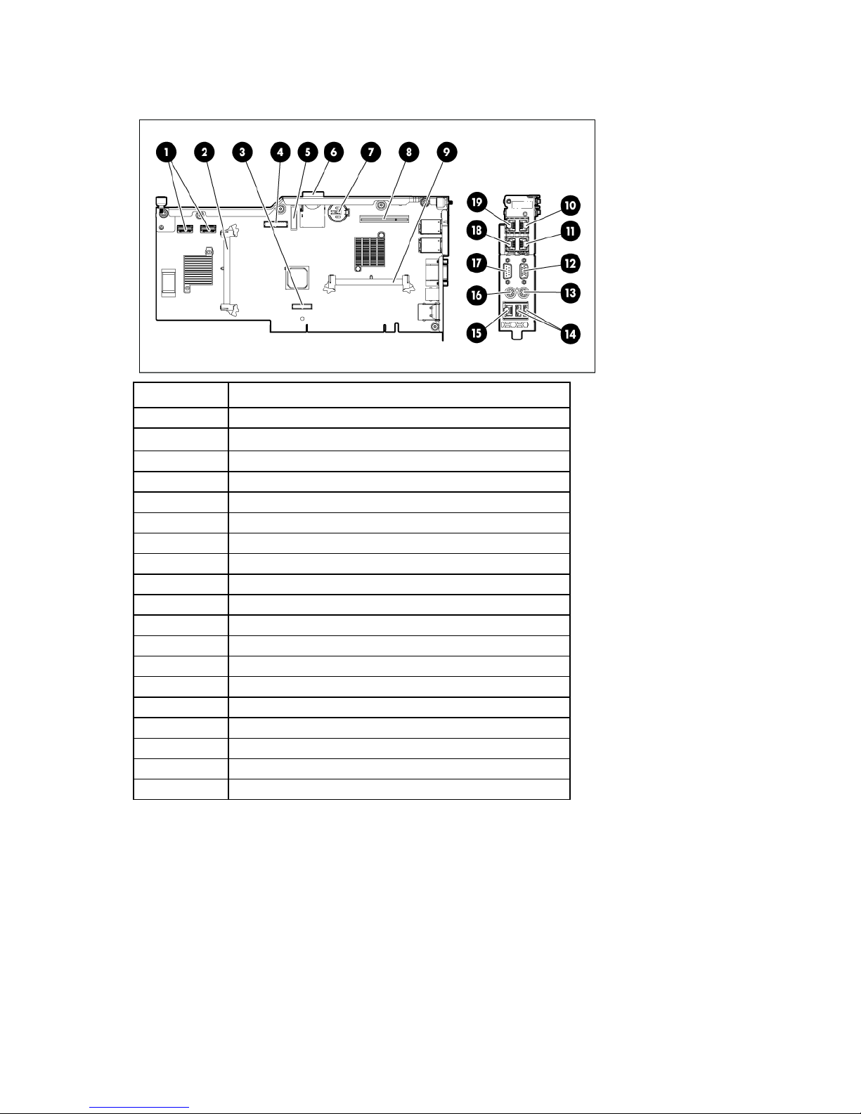
SPI board components
SD card slot
NIC 1 connector
Item Description
1
2
3
4
5
6
7
8
9
10
11
12
13
14
15
16
17
18
19
*Applicable only on the NC375i SPI board
Mini-SAS connectors (2)
SAS cache connector
TPM connector
Fan data connector
RMII connector
Battery
10Gb NIC connector*
NIC cache connector*
NIC 3 connector
Video connector
Keyboard connector
USB connectors (2)
iLO 3 connector
Mouse connector
Serial connector
NIC 2 connector
NIC 4 connector
Component identification 15
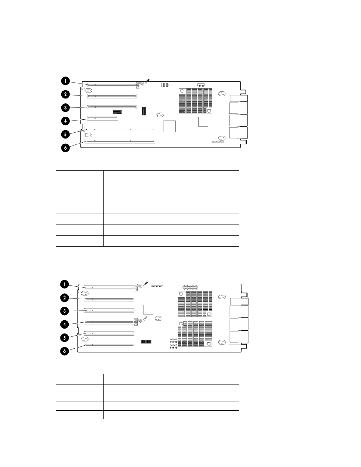
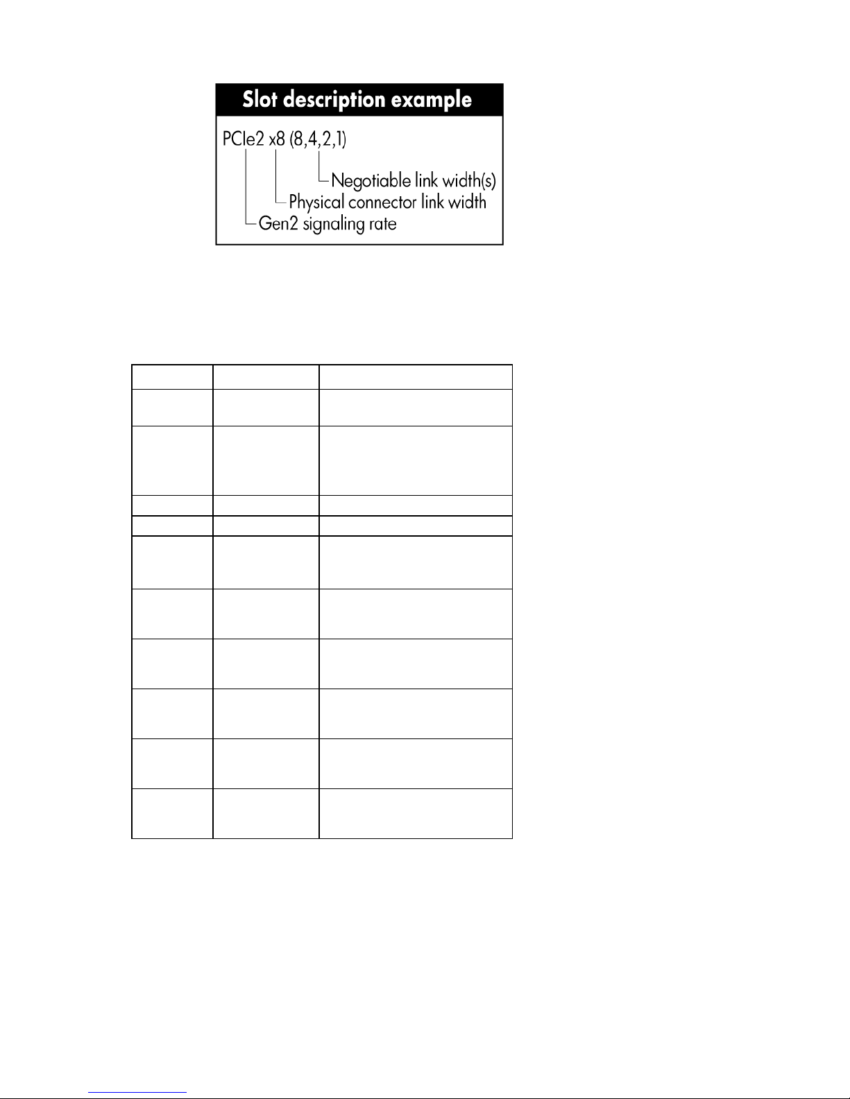
I/O expansion board components
Slot 6 PCIe2 x16 (16, 8, 4, 2, 1)
• PCI-X/PCI Express I/O expansion board
Item Description
1
2
3
4
5
6
Slot 6 PCIe2 x16 (16, 8, 4, 2, 1)
Slot 5 PCIe2 x8 (8, 4, 2, 1)
Slot 4 PCIe2 x8 (8, 4, 2, 1)
Slot 3 PCIe2 x4 (4, 2, 1)
Slot 2 PCI-X
Slot 1 PCI-X
• PCI Express I/O expansion board
Item Description
1
2
3
4
Slot 5 PCIe2 x8 (8, 4, 2, 1)
Slot 4 PCIe2 x8 (8, 4, 2, 1)
Slot 3 PCIe2 x16 (16, 8, 4, 2, 1)
Component identification 16
Item Description
5
6
Slot 2 PCIe2 x8 (8, 4, 2, 1)
Slot 1 PCIe1 x8 (8, 4, 2, 1)
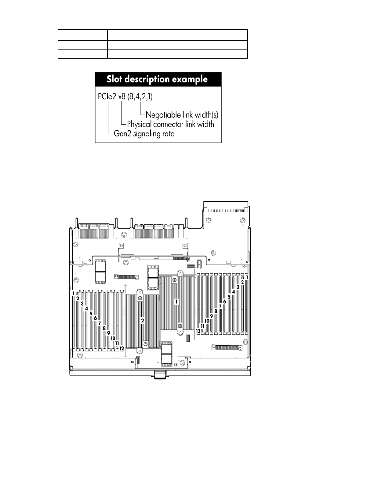
DIMM slot locations
• Primary processor memory board
Component identification 17
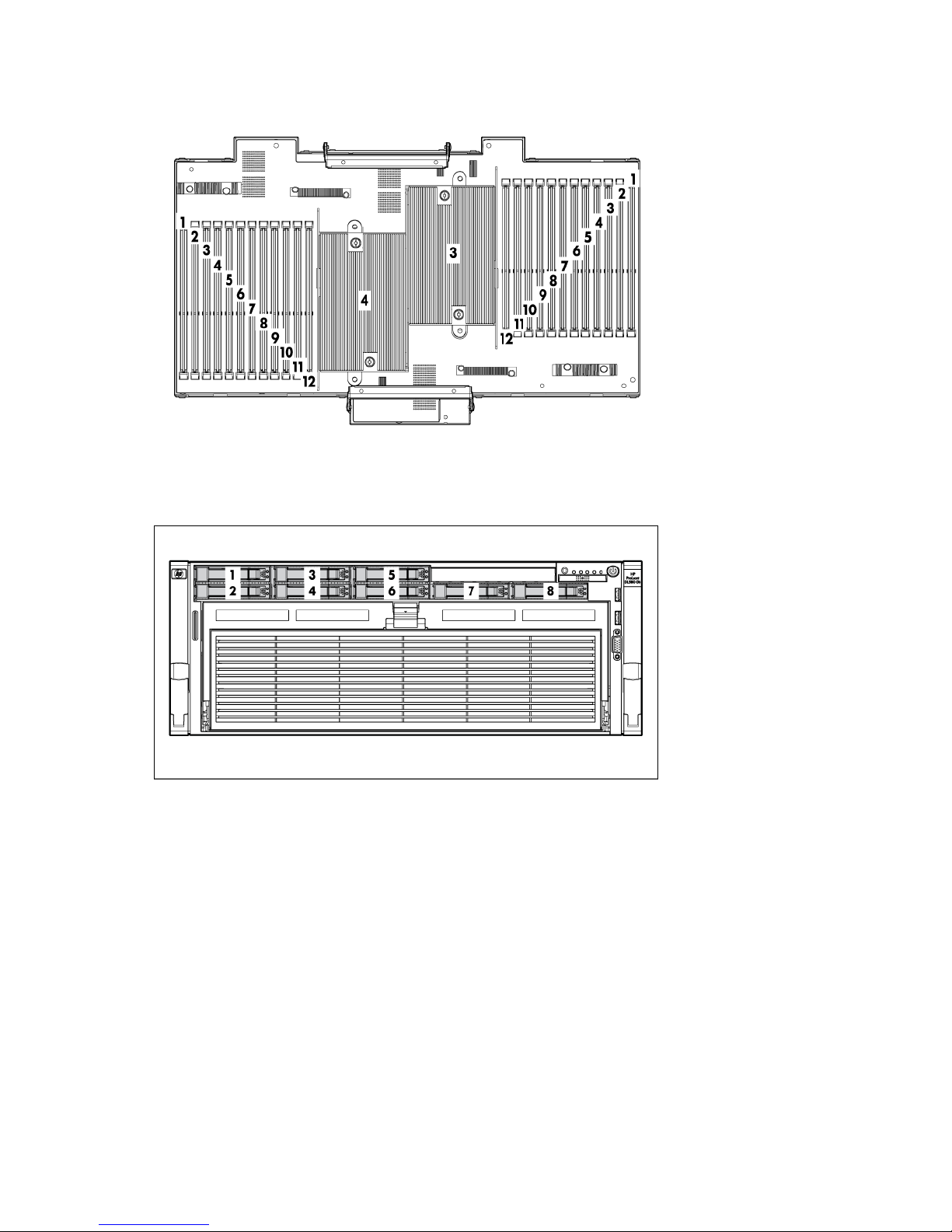
• Secondary processor memory board
Device numbers
Component identification 18
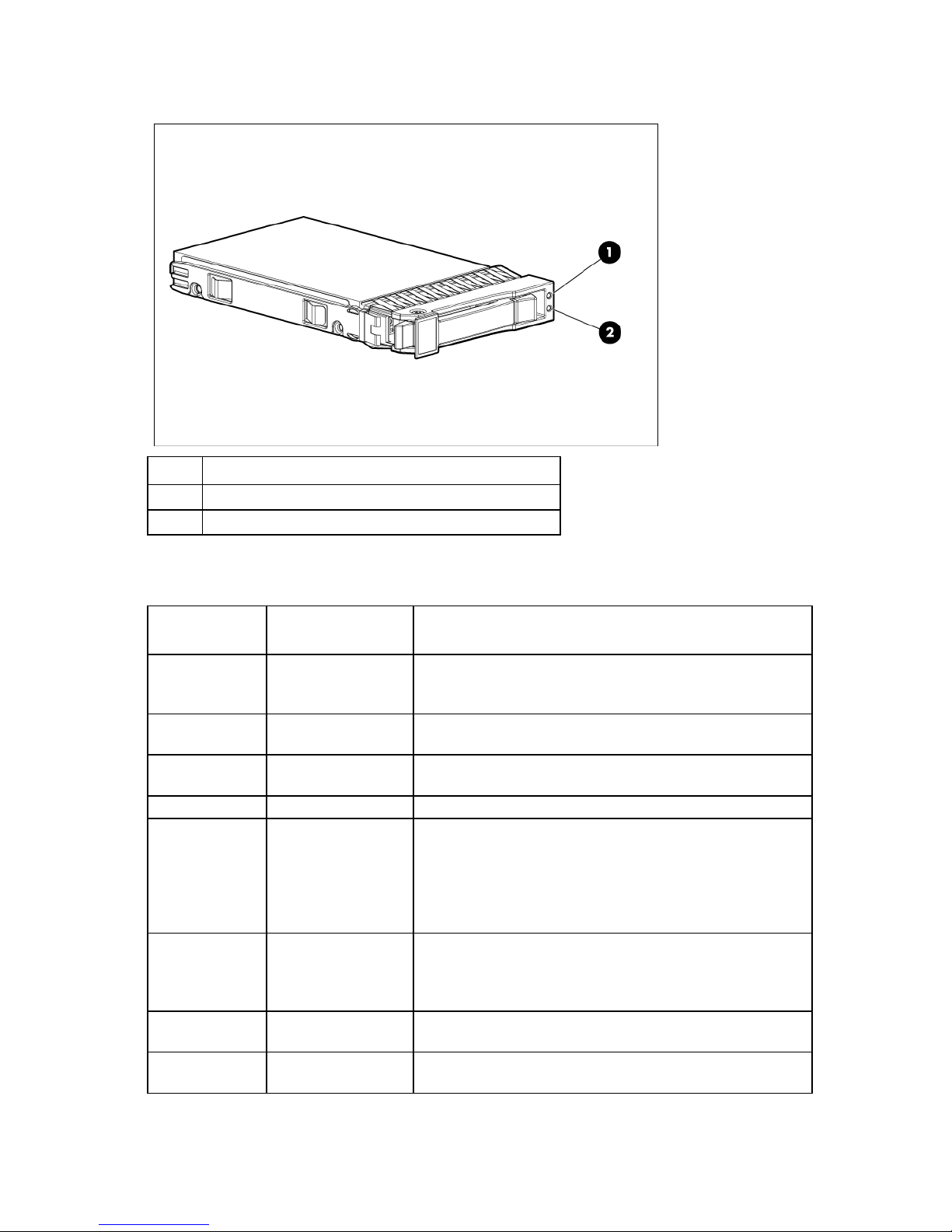
SAS hard drive LEDs
Alternating amber and
Item Description
1
2
Fault/UID LED (amber/blue)
Online LED (green)
SAS hard drive LED combinations
Online/activity
LED (green)
On, off, or
flashing
On, off, or
flashing
On
On
Flashing regularly
(1 Hz)
Flashing regularly
(1 Hz)
Flashing
irregularly
Flashing
irregularly
Fault/UID LED
Interpretation
(amber/blue)
The drive has failed, or a predictive failure alert has been
blue
Steadily blue The drive is operating normally, and it has been selected by a
Amber, flashing
regularly (1 Hz)
Off The drive is online, but it is not active currently.
Amber, flashing
regularly (1 Hz)
Off Do not remove the drive. Removing a drive may terminate the
Amber, flashing
regularly (1 Hz)
Off The drive is active, and it is operating normally.
received for this drive; it also has been selected by a management
application.
management application.
A predictive failure alert has been received for this drive.
Replace the drive as soon as possible.
Do not remove the drive. Removing a drive may terminate the
current operation and cause data loss.
The drive is part of an array that is undergoing capacity
expansion or stripe migration, but a predictive failure alert has
been received for this drive. To minimize the risk of data loss, do
not replace the drive until the expansion or migration is complete.
current operation and cause data loss.
The drive is rebuilding, or it is part of an array that is undergoing
capacity expansion or stripe migration.
The drive is active, but a predictive failure alert has been received
for this drive. Replace the drive as soon as possible.
Component identification 19

Steadily amber
A critical fault condition has been identified for this drive, and the
Online/activity
LED (green)
Fault/UID LED
(amber/blue)
Off
Off
Amber, flashing
regularly (1 Hz)
Off
Off The drive is offline, a spare, or not configured as part of an array.
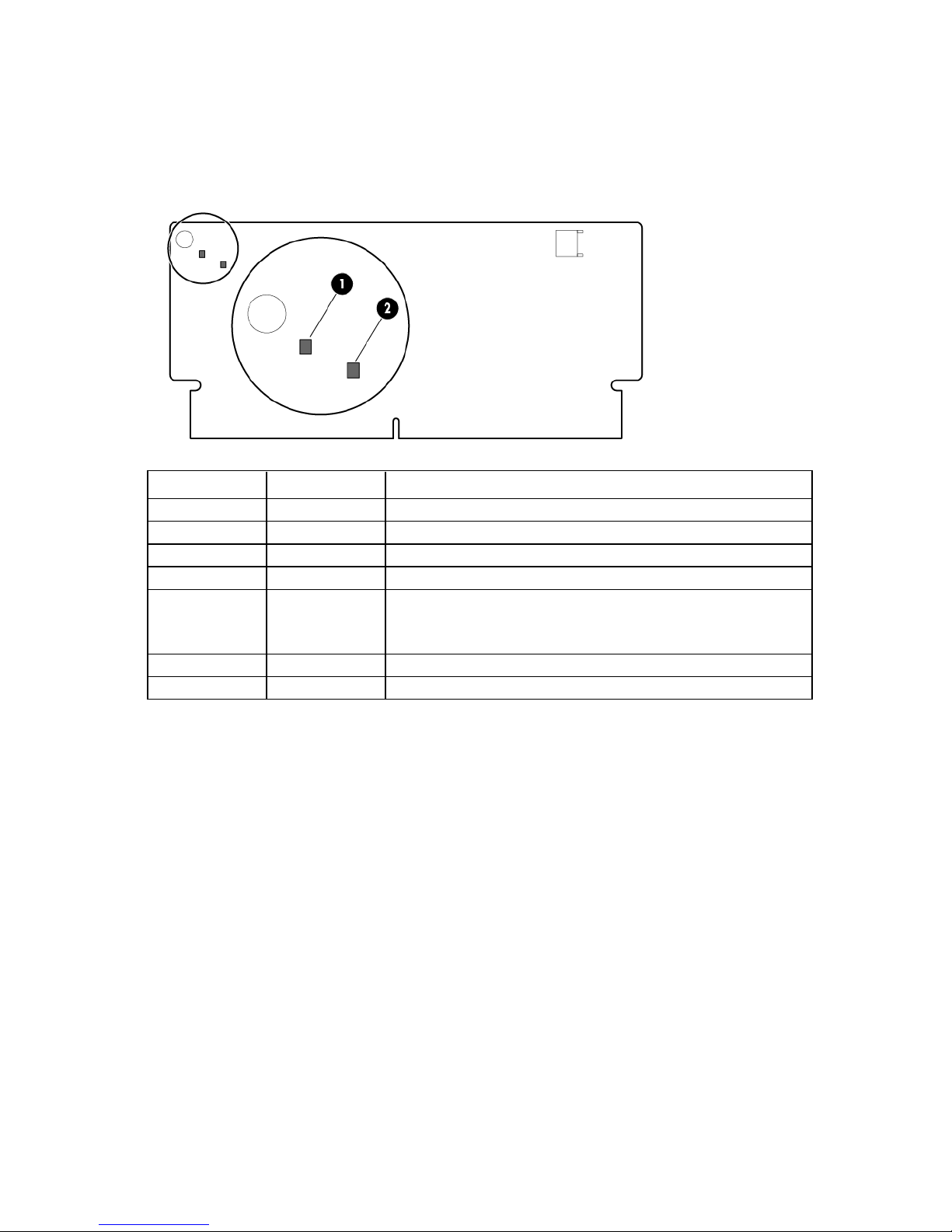
Battery pack LEDs
Interpretation
controller has placed it offline. Replace the drive as soon as
possible.
A predictive failure alert has been received for this drive. Replace
the drive as soon as possible.
Item Color Description
1
2
3
4
Green System Power LED. This LED is on when the system is
powered up and 12 V system power is available. This
power supply is used to maintain the battery charge and
provide supplementary power to the cache microcontroller.
Green Auxiliary Power LED. This LED is on when 3.3V auxiliary
voltage is detected. The auxiliary voltage is used to
preserve BBWC data and is available any time that the
system power cords are connected to a power supply.
Amber Battery Health LED. To interpret the illumination patterns of
this LED, see the following table.
Green BBWC Status LED. To interpret the illumination patterns of
this LED, see the following table.
Component identification 20

power is available, as indicated by LED 2. In the absence of auxiliary
pack. BBWC features are disabled until the battery pack is replaced.
pack. BBWC features are disabled until the battery pack is replaced.
LED3 pattern LED4 pattern Interpretation
Off
Off
Off
Off
Off
Flashing (1 Hz)
On
Flashing (2 Hz) The system is powered down, and the cache contains data that has not
yet been written to the drives. Restore system power as soon as
possible to prevent data loss.
Data preservation time is extended any time that 3.3 V auxiliary
power, battery power alone preserves the data. A fully-charged
battery can normally preserve data for at least 2 days.
The battery lifetime also depends on the cache module size. For more
information, see the controller QuickSpecs on the HP website
(http://www.hp.com).
Double flash, then
pause
The cache microcontroller is waiting for the host controller to
communicate.
Flashing (1 Hz) The battery pack is below the minimum charge level and is being
charged. Features that require a battery (such as write cache, capacity
expansion, stripe size migration, and RAID migration) are unavailable
temporarily until charging is complete. The recharge process takes
between 15 minutes and 2 hours, depending on the initial capacity of
the battery.
On The battery pack is fully charged, and posted write data is stored in the
cache.
Off The battery pack is fully charged, and no posted write data exists in
the cache.
Flashing (1 Hz) An alternating green and amber flashing pattern indicates that the
cache microcontroller is executing from within its boot loader and
receiving new flash code from the host controller.
— A short circuit exists across the battery terminals or within the battery
The life expectancy of a battery pack is typically more than 3 years.
Flashing (1 Hz)
— An open circuit exists across the battery terminals or within the battery
The life expectancy of a battery pack is typically more than 3 years.
Component identification 21
FBWC module LEDs
•
•
The FBWC module has two single-color LEDs (green and amber). The LEDs are duplicated on the reverse side
of the cache module to facilitate status viewing.
1 Green LED 2 Amber LED Interpretation
Off
Flashing (1 Hz)
Flashing (1 Hz)
On
Flashing (2 Hz)
Alternating with
amber LED
On
Off
On A backup is in progress.
On A restore is in progress.
Off The capacitor pack is charging.
Off The capacitor pack has completed charging.
Flashing (2 Hz)
Alternating with
green LED
On The flash code image failed to load.
Off The flash code is corrupt.
One of the following conditions exists:
The charging process has timed out.
The capacitor pack is not connected.
Component identification 22
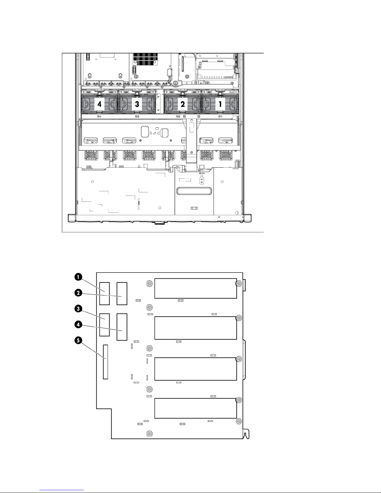
Fan locations
Power supply backplane components
Component identification 23

Item Description
1
2
3
4
5
Graphics card power connector
Graphics card power connector
Graphics card power connector
SAS backplane power connector
Fan power connector
Component identification 24

Operations
Power up the server
To power up the server, press the Power On/Standby button.
Power down the server
WARNING: To reduce the risk of personal injury, electric shock, or damage to the equipment,
remove the power cord to remove power from the server. The front panel Power On/Standby
button does not completely shut off system power. Portions of the power supply and some internal
1. Back up the server data.
2. Shut down the operating system as directed by the operating system documentation.
3. Press the Power On/Standby button to place the server in Standby mode. When the server activates
4. Disconnect the power cords.
circuitry remain active until AC power is removed.
IMPORTANT: If installing a hot-plug device, it is not necessary to power down the server.
NOTE: If the operating system automatically places the server in Standby mode, omit the next
step.
Standby power mode, the system power LED changes to amber.
IMPORTANT: Pressing the UID button illuminates the blue UID LEDs on the front and rear panels.
In a rack environment, this feature facilitates locating a server when moving between the front and
rear of the rack.
The system is now without power.
Extend the server from the rack
WARNING: To reduce the risk of personal injury or equipment damage, be sure that the rack is
To extend the server from the rack:
1. Pull down the quick-release levers on each side of the server to release the server from the rack.
adequately stabilized before extending a component from the rack.
WARNING: To reduce the risk of personal injury, be careful when pressing the server rail-release
latches and sliding the server into the rack. The sliding rails could pinch your fingers.
Operations 25
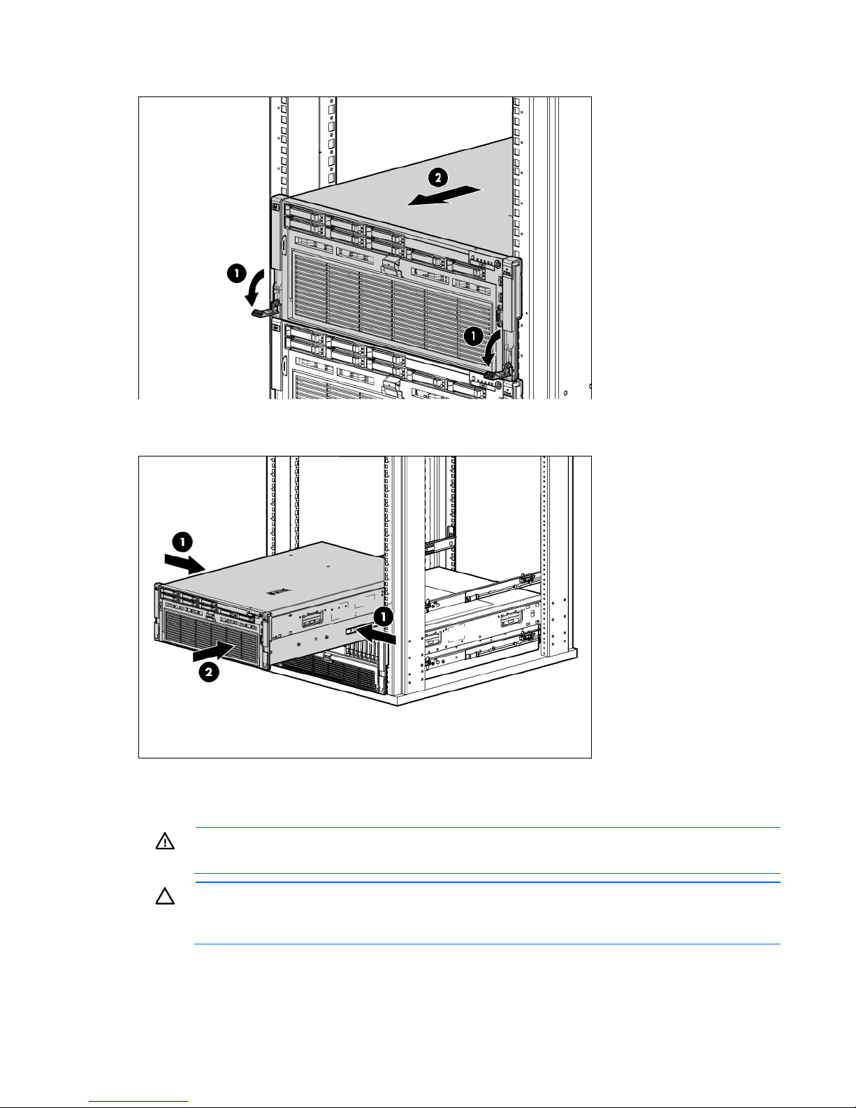
2.
Extend the server on the rack rails until the server rail-release latches engage.
3. After performing the installation or maintenance procedure, slide the server into the rack by pressing the
server rail-release latches.
Remove the access panel
WARNING: To reduce the risk of personal injury from hot surfaces, allow the drives and the
To remove the component:
1. Power down the server (on page 25).
internal system components to cool before touching them.
CAUTION: Do not operate the server for long periods with the access panel open or removed.
Operating the server in this manner results in improper airflow and improper cooling that can
lead to thermal damage.
Operations 26
2.
Extend the server from the rack (on page 25).
3. Open the locking latch, slide the access panel to the rear of the chassis, and remove the access panel.
If the locking latch is locked, use a T-15 Torx screwdriver to unlock the latch.
Install the access panel
1. Place the access panel on top of the server.
2. Slide the access panel forward until it clicks into place.
Remove the processor memory drawer
1. Power down the server (on page 25).
2. Remove the processor memory drawer shipping screws, if installed. Retain the screws for future use.
3. Release the latches on the release lever.
4. Lower the handle, and then extend the processor memory drawer from the server until the release
latches catch.
WARNING: The processor memory drawer weighs more than 11.3 kg (25.0 lb). Use extra
caution when removing and replacing the processor memory drawer.
Operations 27
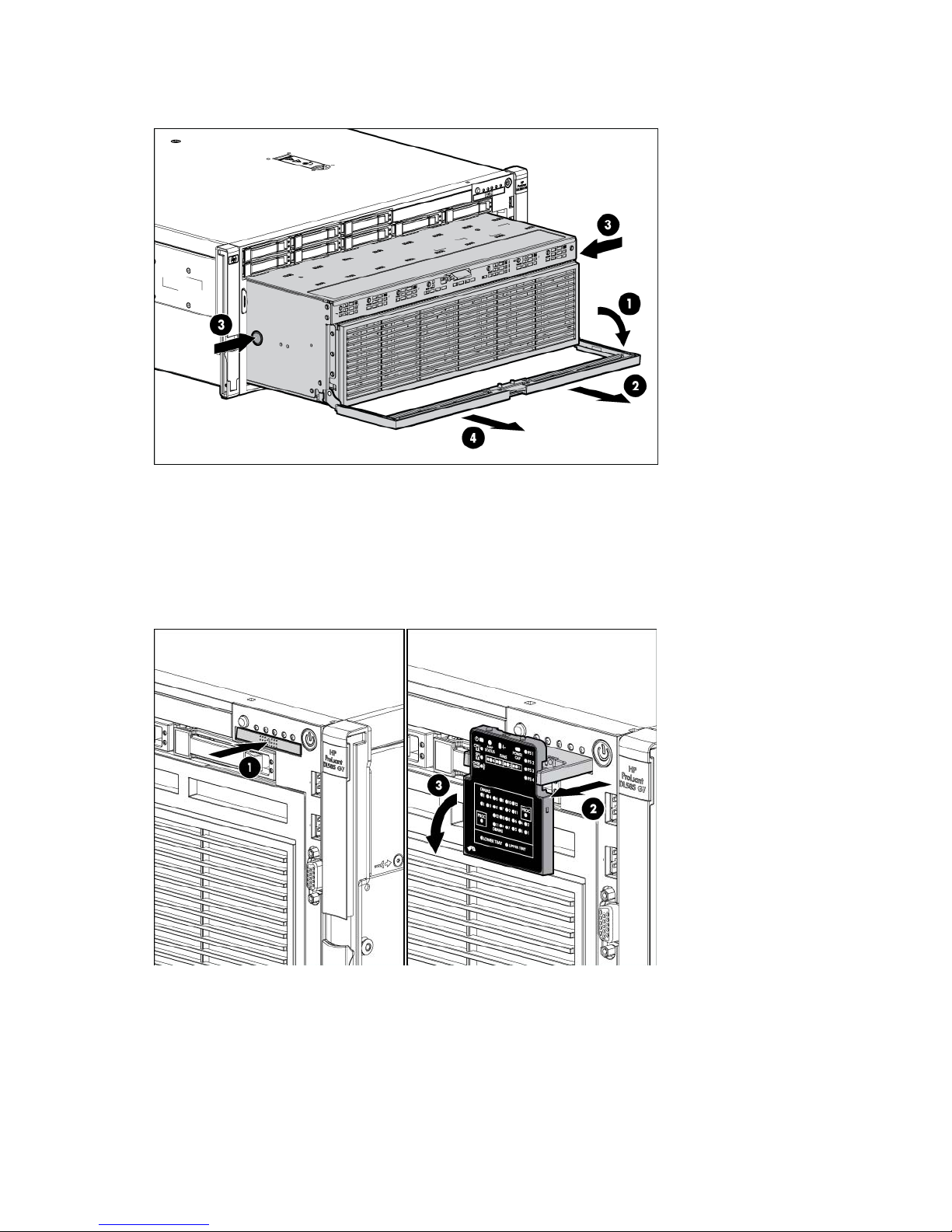
5.
Firmly holding the processor memory drawer, press the release buttons and then remove the drawer
from the server.
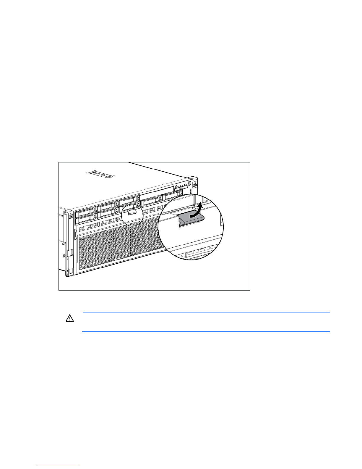
Access the Systems Insight Display
To access the Systems Insight Display:
1. Press and release the panel.
2. After the display fully ejects, rotate the display downward to view the LEDs.
Remove the SPI board
To remove the component:
1. Power off the server.
2. Extend the server from the rack (on page 25).
Operations 28
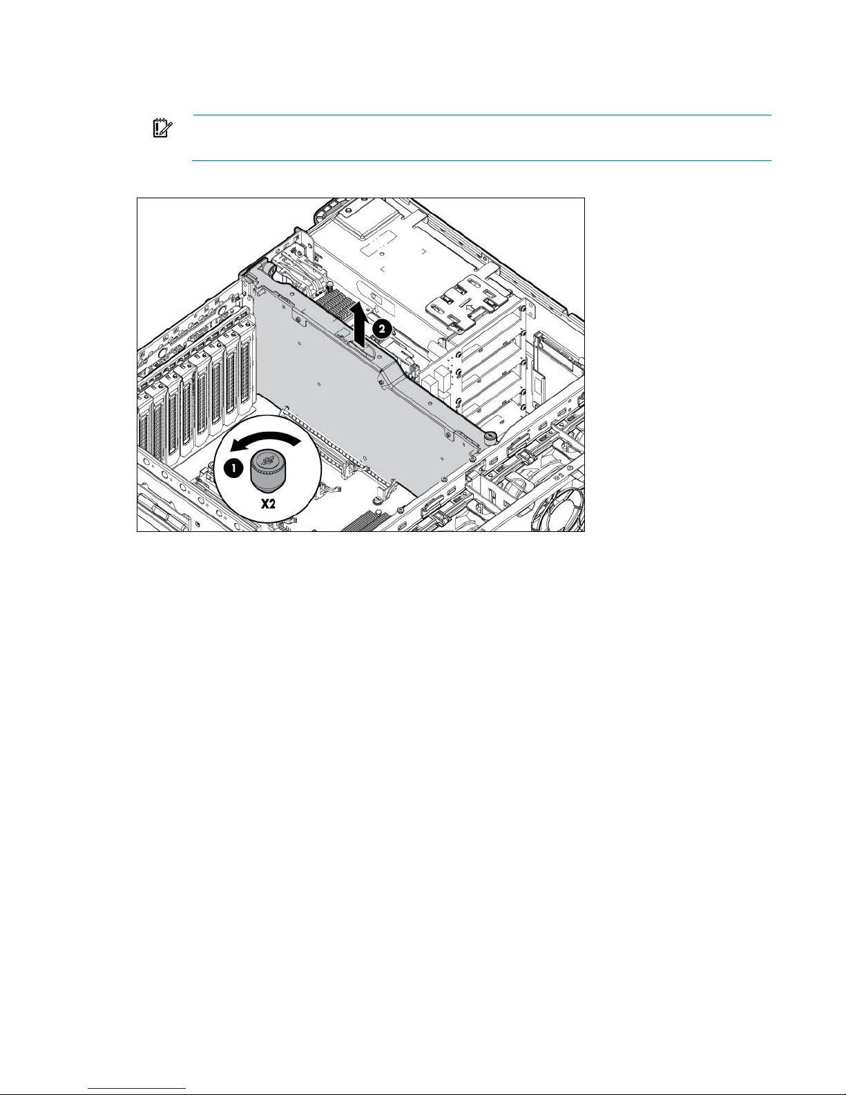
3.
Remove the access panel (on page 26).
4. Disconnect all cables from the SPI board.
IMPORTANT: If replacing the SPI board or clearing NVRAM, you must re-enter the server serial
number through RBSU ("Re-entering the server serial number and product ID" on page 76).
5. Raise the levers, and lift the SPI board from the server.
6. Remove all components from the failed SPI board.
To replace the component, reverse the removal procedure.
Operations 29

Setup
Optional installation services
Delivered by experienced, certified engineers, HP Care Pack services help you keep your servers up and
running with support packages tailored specifically for HP ProLiant systems. HP Care Packs let you integrate
both hardware and software support into a single package. A number of service level options are available
to meet your needs.
HP Care Pack Services offer upgraded service levels to expand your standard product warranty with
easy-to-buy, easy-to-use support packages that help you make the most of your server investments. Some of
the Care Pack services are:
• Hardware support
o 6-Hour Call-to-Repair
o 4-Hour 24x7 Same Day
o 4-Hour Same Business Day
• Software support
o Microsoft®
o Linux
o HP ProLiant Essentials (HP SIM and RDP)
o VMware
• Integrated hardware and software support
o Critical Service
o Proactive 24
o Support Plus
o Support Plus 24
• Startup and implementation services for both hardware and software
For more information on HP Care Pack Services, see the HP website
(http://www.hp.com/services/carepack).
Rack planning resources
The rack resource kit ships with all HP branded or Compaq branded 9000, 10000, and H9 series racks. For
more information on the content of each resource, see the rack resource kit documentation.
Optimum environment
When installing the server, select a location that meets the environmental standards described in this section.
Setup 30
 Loading...