

HP ProLiant DL380p G8 User Manual

HP ProLiant DL380p Gen8 Server
User Guide
Abstract
This document is for the person who installs, administers, and troubleshoots servers and storage systems. HP assumes you are qualified in the
servicing of computer equipment and trained in recognizing hazards in products with hazardous energy levels.
Part Number: 661848-005a
August 2013
Edition: 5

© Copyright 2012, 2013 Hewlett-Packard Development Company, L.P.
The information contained herein is subject to change without notice. The only warranties for HP products and services are set forth in the express
warranty statements accompanying such products and services. Nothing herein should be construed as constituting an additional warranty. HP shall
not be liable for technical or editorial errors or omissions contained herein.
Microsoft®, Windows®, and Windows Server® are U.S. registered trademarks of Microsoft Corporation.

Contents
Component identification ............................................................................................................... 7
Front panel components ............................................................................................................................. 7
Front panel LEDs and buttons ...................................................................................................................... 9
Access the Systems Insight Display ............................................................................................................. 10
Systems Insight Display LEDs ..................................................................................................................... 11
Systems Insight Display LED combinations ................................................................................................... 12
Rear panel components ............................................................................................................................ 13
Rear panel LEDs and buttons ..................................................................................................................... 14
Non-hot-plug PCI riser board slot definitions ................................................................................................ 14
System board components ........................................................................................................................ 15
System maintenance switch ............................................................................................................. 16
NMI functionality ........................................................................................................................... 17
DIMM slot locations ....................................................................................................................... 18
SAS and SATA device numbers ................................................................................................................. 18
Hot-plug drive LED definitions .................................................................................................................... 19
PCI riser cage LED ................................................................................................................................... 20
FBWC module LEDs (P222, P420, P421) ................................................................................................... 21
Hot-plug fans .......................................................................................................................................... 21
Operations ................................................................................................................................. 23
Power up the server ................................................................................................................................. 23
Power down the server ............................................................................................................................. 23
Extend the server from the rack ................................................................................................................. 23
Remove the access panel.......................................................................................................................... 24
Install the access panel............................................................................................................................. 25
Access the product rear panel ................................................................................................................... 25
Opening the cable management arm ............................................................................................... 25
Remove the hot-plug fan cage ................................................................................................................... 26
Remove the hot-plug fan ........................................................................................................................... 27
Remove the full-length expansion board ...................................................................................................... 28
Remove the PCI riser cage ........................................................................................................................ 29
Install the PCI riser cage ........................................................................................................................... 30
Secure the full-length expansion board retainer ........................................................................................... 31
Remove the air baffle ............................................................................................................................... 32
Setup ......................................................................................................................................... 34
Optional installation services .................................................................................................................... 34
Optimum environment .............................................................................................................................. 34
Space and airflow requirements ...................................................................................................... 34
Temperature requirements ............................................................................................................... 35
Power requirements ....................................................................................................................... 36
Electrical grounding requirements .................................................................................................... 36
Connecting a DC power cable to a DC power source ........................................................................ 36
Rack warnings ........................................................................................................................................ 37
Identifying the contents of the server shipping carton .................................................................................... 38
Installing hardware options ....................................................................................................................... 38
Installing the server into the rack ................................................................................................................ 38
Contents 3

Installing the operating system................................................................................................................... 40
Powering on and selecting boot options ..................................................................................................... 40
Registering the server ............................................................................................................................... 41
Hardware options installation ....................................................................................................... 42
Introduction ............................................................................................................................................ 42
Processor and fan option .......................................................................................................................... 42
Memory options ...................................................................................................................................... 49
HP SmartMemory .......................................................................................................................... 49
Memory subsystem architecture ....................................................................................................... 50
Single-, dual-, and quad-rank DIMMs ............................................................................................... 50
DIMM identification ....................................................................................................................... 51
Memory configurations ................................................................................................................... 51
General DIMM slot population guidelines ......................................................................................... 53
Installing a DIMM .......................................................................................................................... 54
Hot-plug hard drive options ...................................................................................................................... 55
Installing a hot-plug SAS or SATA hard drive .................................................................................... 55
Removing a hot-plug SAS or SATA hard drive ................................................................................... 56
Controller options .................................................................................................................................... 57
Installing the flash-backed write cache module................................................................................... 58
Installing the flash-backed write cache capacitor pack ........................................................................ 59
Optical drive option ................................................................................................................................ 63
Redundant hot-plug power supply option .................................................................................................... 65
48V DC power supply option ................................................................................................................... 66
FlexibleLOM option ................................................................................................................................. 70
Expansion board options .......................................................................................................................... 72
Removing the expansion slot blanks ................................................................................................. 72
Installing a half-length expansion board ........................................................................................... 73
Installing a full-length expansion board ............................................................................................. 73
Secondary PCI riser cage option ............................................................................................................... 74
Hard drive cage option ............................................................................................................................ 76
2U rack bezel option ............................................................................................................................... 85
HP Trusted Platform Module option ............................................................................................................ 86
Installing the Trusted Platform Module board ..................................................................................... 87
Retaining the recovery key/password .............................................................................................. 88
Enabling the Trusted Platform Module ............................................................................................... 88
Cabling ..................................................................................................................................... 90
SAS hard drive cabling ............................................................................................................................ 90
Optical drive cabling ............................................................................................................................... 91
FBWC cabling ........................................................................................................................................ 92
Chipset SATA cable option ....................................................................................................................... 93
150W PCIe power cable option ............................................................................................................... 96
Software and configuration utilities ...............................................................................................
Server mode ........................................................................................................................................... 98
HP product QuickSpecs ............................................................................................................................ 98
HP iLO Management Engine ..................................................................................................................... 98
HP iLO ......................................................................................................................................... 98
Intelligent Provisioning .................................................................................................................. 100
HP Insight Remote Support software ............................................................................................... 102
Scripting Toolkit .......................................................................................................................... 102
HP Service Pack for ProLiant ................................................................................................................... 102
HP Smart Update Manager ........................................................................................................... 102
98
Contents 4

HP ROM-Based Setup Utility ................................................................................................................... 103
Using RBSU ................................................................................................................................ 103
Auto-configuration process ............................................................................................................ 104
Boot options ............................................................................................................................... 104
Configuring AMP modes .............................................................................................................. 105
Re-entering the server serial number and product ID ......................................................................... 105
Utilities and features .............................................................................................................................. 105
Array Configuration Utility ............................................................................................................ 105
HP Smart Storage Administrator .................................................................................................... 106
Option ROM Configuration for Arrays ........................................................................................... 107
ROMPaq utility ............................................................................................................................ 107
Automatic Server Recovery ........................................................................................................... 107
USB support ................................................................................................................................ 108
Redundant ROM support .............................................................................................................. 108
Keeping the system current ..................................................................................................................... 108
Drivers ....................................................................................................................................... 108
Software and firmware ................................................................................................................. 109
Version control ............................................................................................................................ 109
HP operating systems and virtualization software support for ProLiant servers ...................................... 109
HP Technology Service Portfolio .................................................................................................... 109
Change control and proactive notification ...................................................................................... 110
Troubleshooting ........................................................................................................................ 111
Troubleshooting resources ...................................................................................................................... 111
Battery replacement .................................................................................................................. 112
Regulatory information .............................................................................................................. 113
Safety and regulatory compliance ........................................................................................................... 113
Turkey RoHS material content declaration ................................................................................................. 113
Ukraine RoHS material content declaration ............................................................................................... 113
Warranty information ............................................................................................................................ 113
Electrostatic discharge ............................................................................................................... 114
Preventing electrostatic discharge ............................................................................................................ 114
Grounding methods to prevent electrostatic discharge ................................................................................ 114
Specifications ........................................................................................................................... 115
Environmental specifications ................................................................................................................... 115
Mechanical specifications ...................................................................................................................... 115
Power supply specifications .................................................................................................................... 115
HP 460 W CS HE Power Supply (92% efficiency) ........................................................................... 116
HP 460 W CS Platinum Power Supply (94% efficiency) .................................................................... 116
HP 500 W CS 277 V AC power supply (94% efficiency) ................................................................. 117
HP 750 W CS 277 V AC power supply (94% efficiency) ................................................................. 117
HP 750 W CS HE Power Supply (92% efficiency) ........................................................................... 117
HP 750 W CS Titanium power supply (96% efficiency) .................................................................... 118
HP 750 W CS Platinum Power Supply (94% efficiency) .................................................................... 118
HP 750 W 48V CS Power Supply ................................................................................................. 119
HP 1200 W CS HE Power Supply (94% efficiency) ......................................................................... 119
Support and other resources ...................................................................................................... 120
Before you contact HP ............................................................................................................................ 120
HP contact information ........................................................................................................................... 120
Customer Self Repair ............................................................................................................................. 120
Contents 5

Acronyms and abbreviations ...................................................................................................... 128
Documentation feedback ........................................................................................................... 131
Index ....................................................................................................................................... 132
Contents 6
Component identification
Front panel components
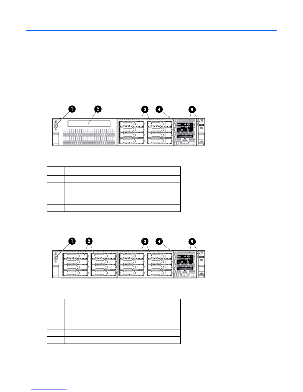
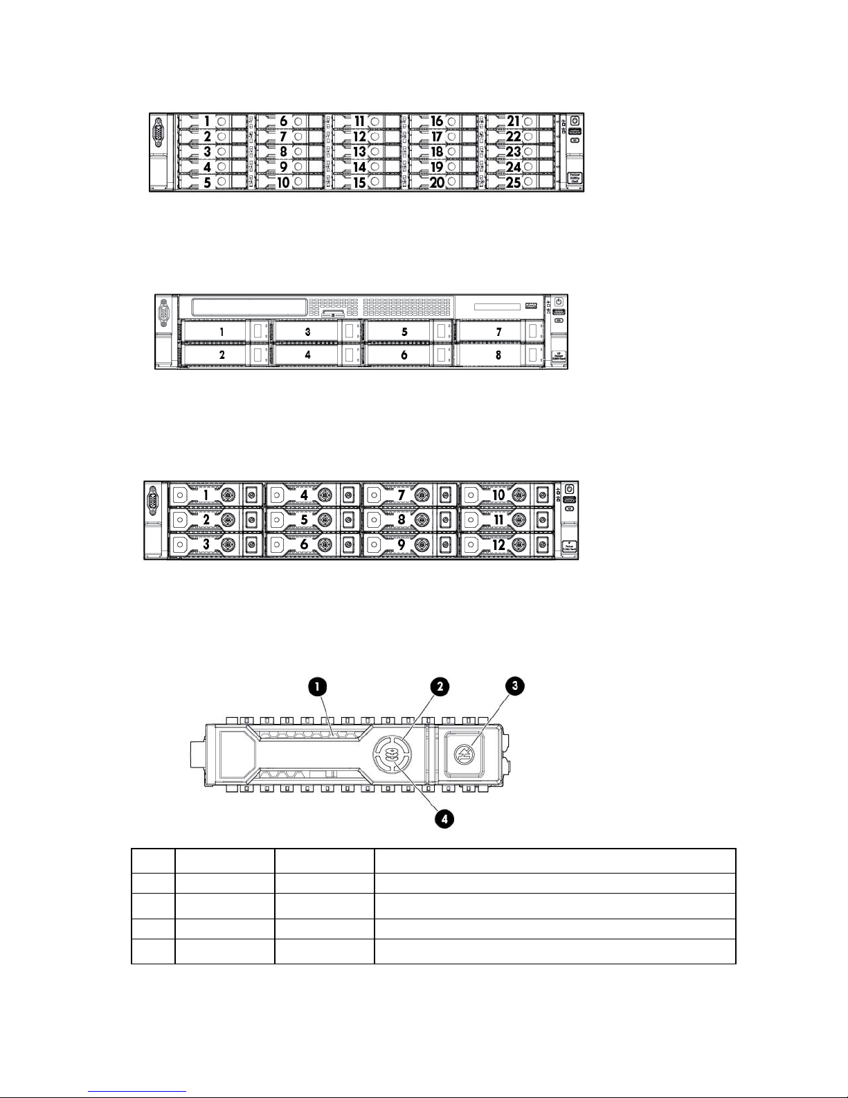
• SFF model (8-drive)
Item Description
1
2
3
4
5
Video connector
SATA optical drive bay
Drive bays
Systems Insight Display
USB connectors (2)
• SFF model with optional hard drive cage (16-drive)
Item Description
1
2
3
4
5
Video connector
Drive bays (box 1)
Drive bays (box 2)
Systems Insight Display
USB connectors (2)
Component identification 7
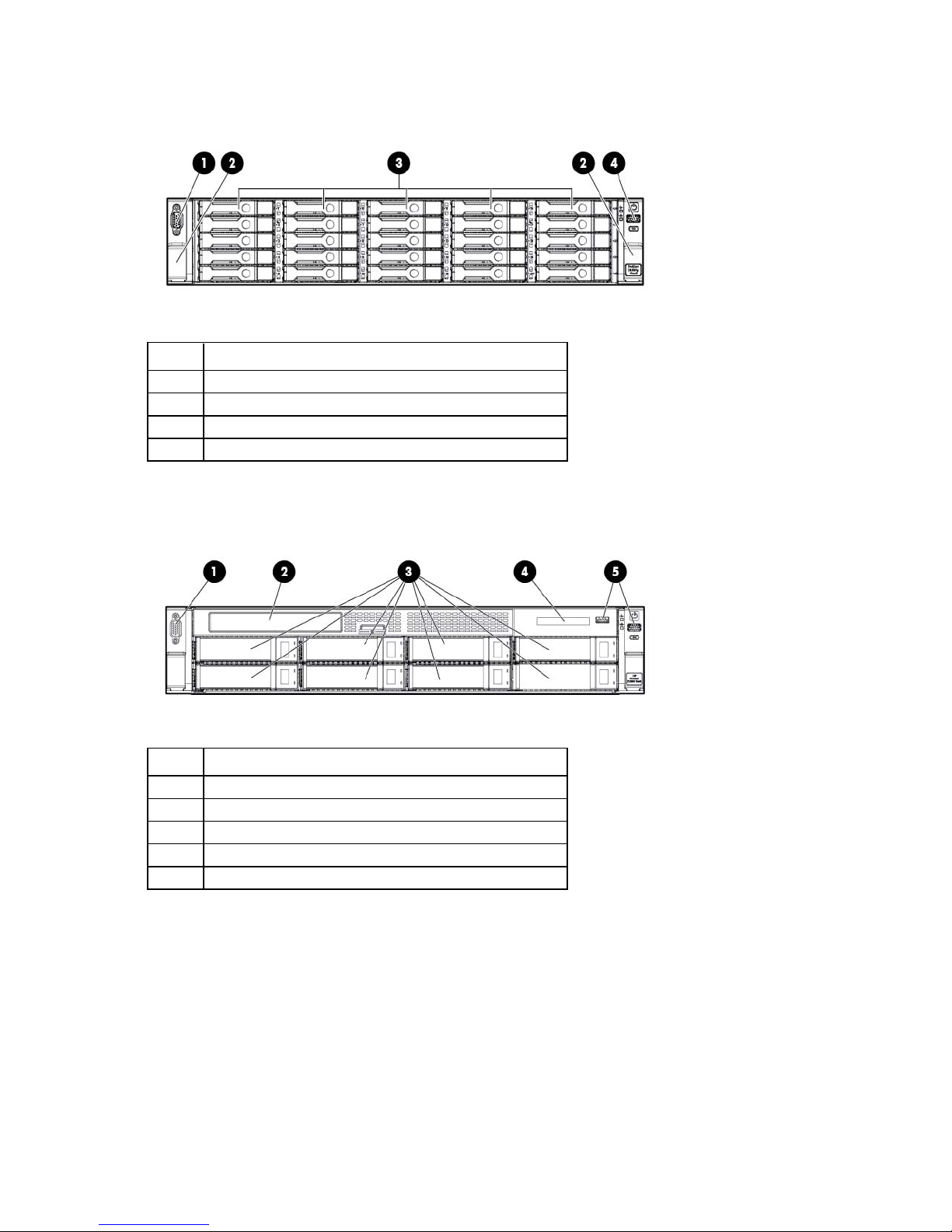
• SFF model (25-drive)
SATA optical drive bay
Item Description
1
2
3
4
Video connector
Quick release levers (2)
Drive bays
USB connector
• LFF model (8-drive)
Item Description
1
2
3
4
5
Video connector
Drive bays
Systems Insight Display
USB connectors (2)
Component identification 8
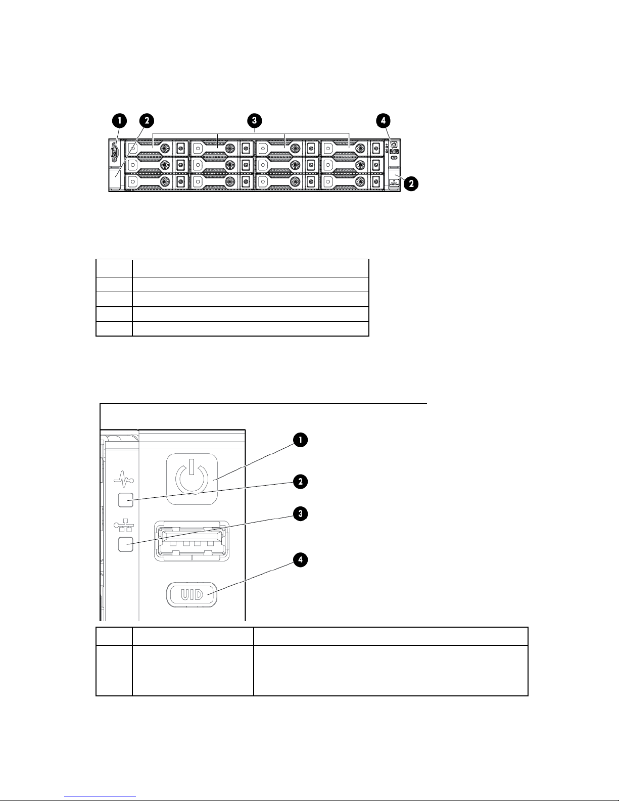
• LFF model (12-drive)
Item Description
1
2
3
4
Video connector
Quick-release levers (2)
Drive bays
USB connector
Front panel LEDs and buttons
Item Description Status
1
Power On/Standby button
and system power LED
Solid green = System on
Flashing green (1 Hz/cycle per sec) = Performing power on sequence
Solid amber = System in standby
Off = No power present*
Component identification 9
Item Description Status
2
Health LED Solid green = Normal
Flashing amber = System degraded
Flashing red (1 Hz/cycle per sec) = System critical
Fast-flashing red (4 Hz/cycles per sec) = Power fault**
3
NIC status LED Solid green = Link to network
Flashing green (1 Hz/cycle per sec) = Network active
Off = No network activity
4
UID button/LED Solid blue = Activated
Flashing blue (1 Hz/cycle per sec) = Remote management or
firmware upgrade in progress
Off = Deactivated
*Facility power is not present, power cord is not attached, no power supplies are installed, power supply failure has
occurred, or the power button cable is disconnected.
**To identify components in a degraded or critical state, see the Systems Insight Display LEDs, check iLO/BIOS logs, and
reference the server troubleshooting guide.
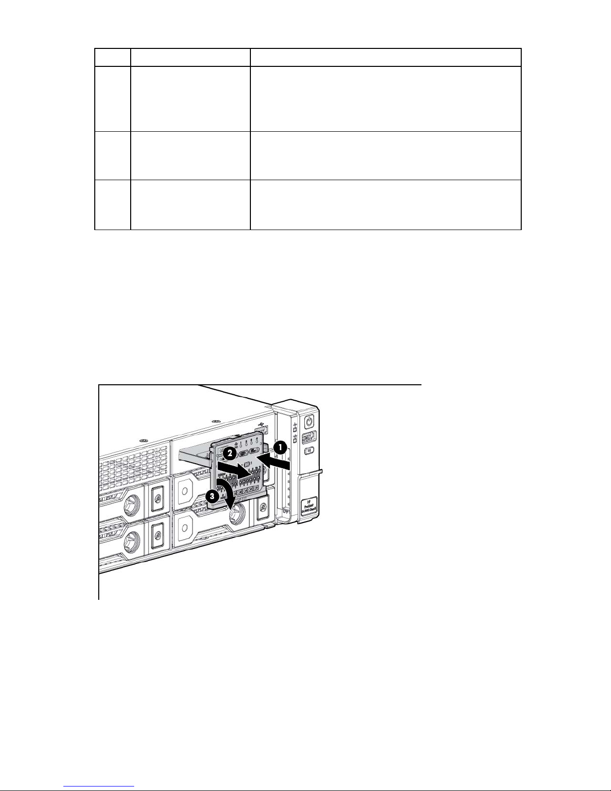
Access the Systems Insight Display
To access a pop-out HP Systems Insight Display:
1. Press and release the panel.
2. After the display fully ejects, rotate the display downward to view the LEDs.
Component identification 10
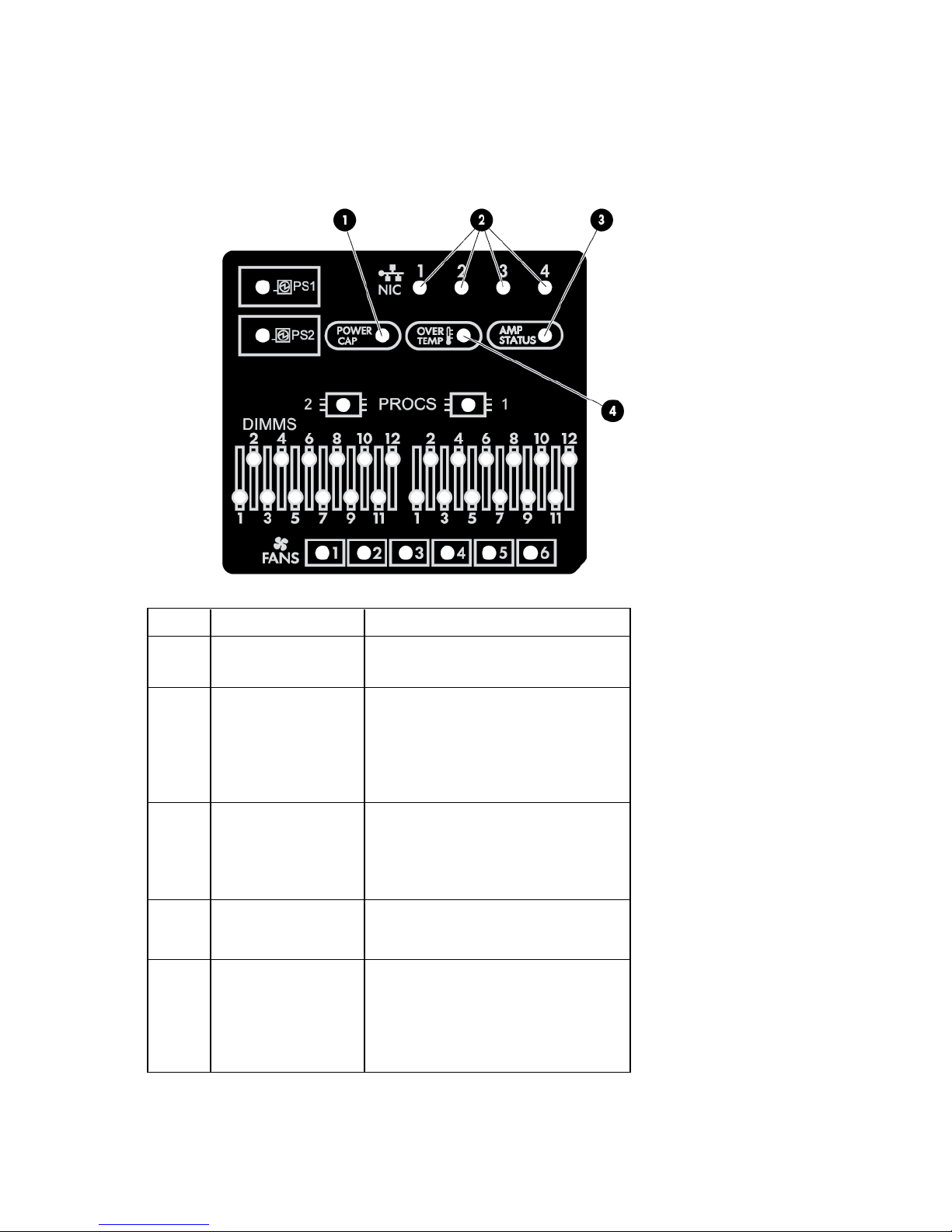
Systems Insight Display LEDs
The HP Systems Insight Display LEDs represent the system board layout. The display enables diagnosis with
the access panel installed.
Item Description Status
1
2
3
4
—
Power cap Off = System is in standby, or no cap is set.
Solid green = Power cap applied
NIC link/activity Off = No link to network. If the power is off,
view the rear panel RJ-45 LEDs for status
("Rear panel LEDs and buttons" on page
14).
Flashing green = Network link and activity
Solid green = Network link
AMP status Off = AMP modes disabled
Solid green = AMP mode enabled
Solid amber = Failover
Flashing amber = Invalid configuration
Over temp Off = Normal
Solid amber = High system temperature
detected
All other LEDs Off = Normal
Amber = Failure
For more information on the activation of
these LEDs, see "Systems Insight Display
LED combinations (on page 12)."
Component identification 11
•
•
•
•
•
•
•
•
•
•
•
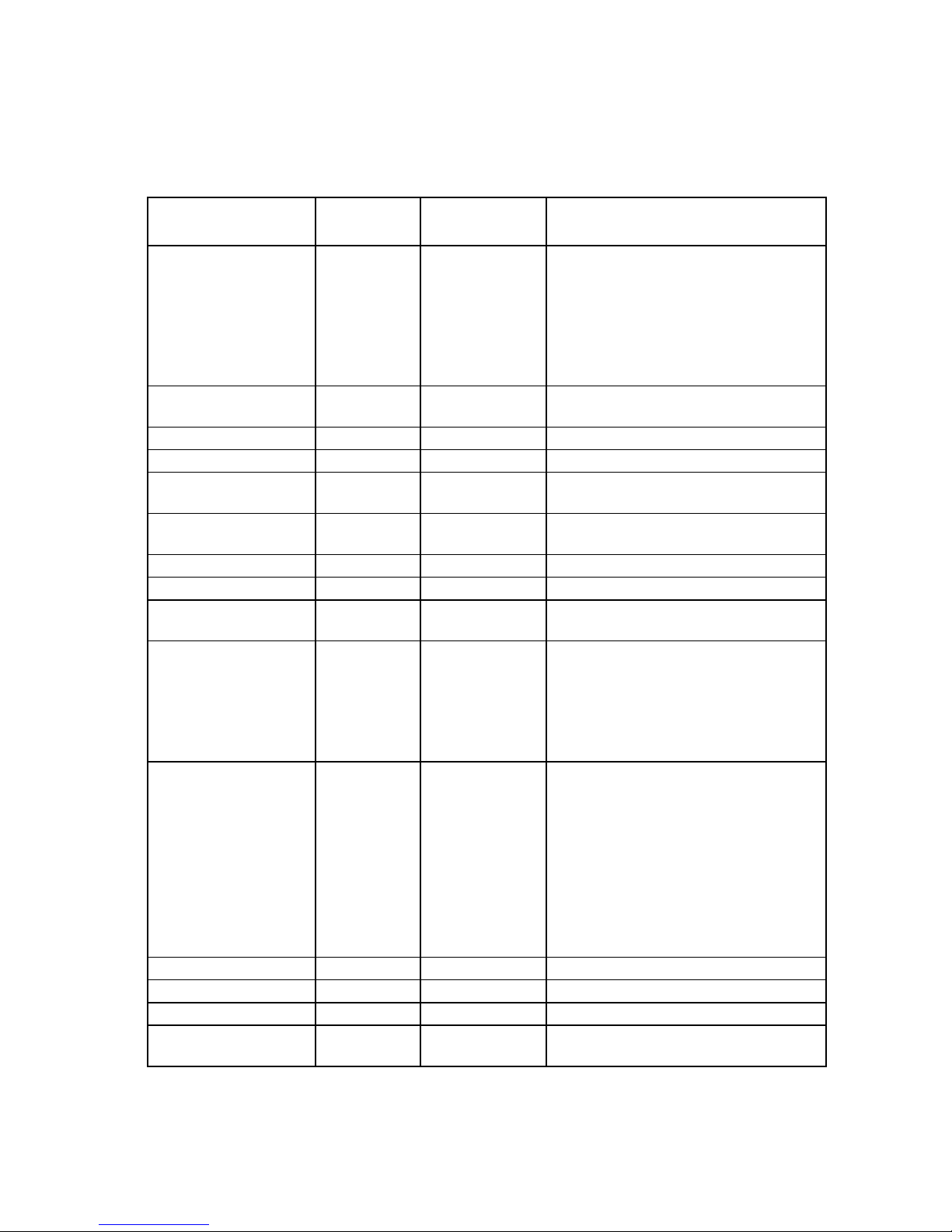
Systems Insight Display LED combinations
When the health LED on the front panel illuminates either amber or red, the server is experiencing a health
event. Combinations of illuminated Systems Insight Display LEDs, the system power LED, and the health LED
indicate system status.
Systems Insight Display
LED and color
Processor (amber)
Processor (amber)
DIMM (amber)
DIMM (amber)
Over temp (amber)
Over temp (amber)
PCI riser (amber)
Fan (amber)
Fan (amber)
Power supply (amber)
Power supply (amber)
Power cap (off)
Power cap (green)
Power cap (green)
Power cap (flashing
amber)
Health LED System power
Status
LED
Red Amber One or more of the following conditions may
exist:
Processor in socket X has failed.
Processor X is not installed in the socket.
Processor X is unsupported.
ROM detects a failed processor during
POST.
Amber Green Processor in socket X is in a pre-failure
condition.
Red Green One or more DIMMs have failed.
Amber Green DIMM in slot X is in a pre-failure condition.
Amber Green The Health Driver has detected a cautionary
temperature level.
Red Amber The server has detected a hardware critical
temperature level.
Red Green The PCI riser cage is not seated properly.
Amber Green One fan has failed or has been removed.
Red Green Two or more fans have failed or been
removed.
Red Amber One or more of the following conditions may
exist:
Only one power supply is installed and
that power supply is in standby.
Power supply fault
System board fault
Amber Green One or more of the following conditions may
exist:
Redundant power supply is installed and
only one power supply is functional.
AC power cord is not plugged into
redundant power supply.
Redundant power supply fault
Power supply mismatch at POST or
power supply mismatch through hot-plug
addition
— Amber Standby
— Flashing green Waiting for power
— Green Power is available.
— Amber Power is not available.
Component identification 12
IMPORTANT: If more than one DIMM slot LED is illuminated, further troubleshooting is required.
Test each bank of DIMMs by removing all other DIMMs. Isolate the failed DIMM by replacing
each DIMM in a bank with a known working DIMM.
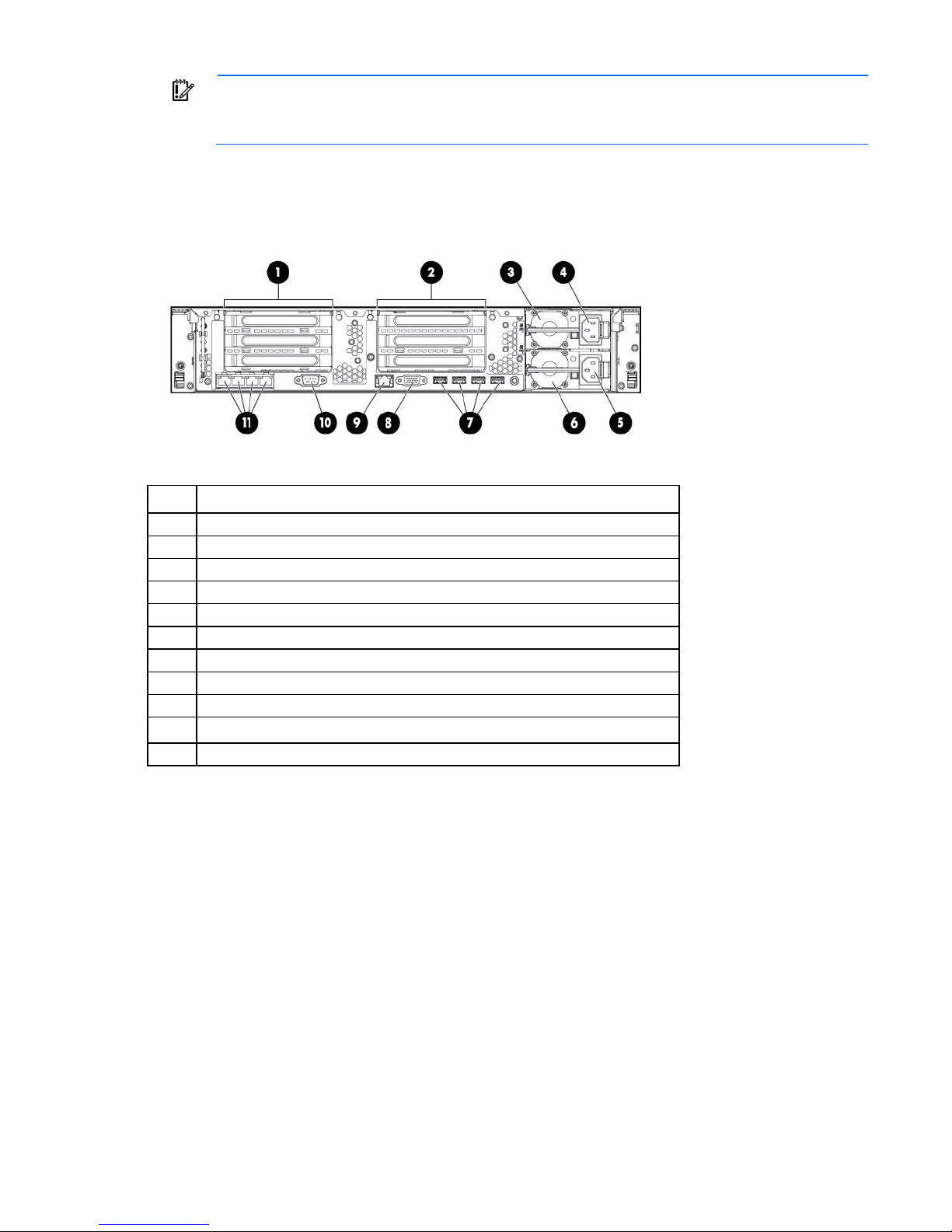
Rear panel components
Item Description
1
2
3
4
5
6
7
8
9
10
11
PCIe slots 1–3 (top to bottom)
PCIe slots 4–6 (top to bottom)
Power supply 1 (PS1)
PS1 power connector
PS2 power connector
Power supply 2 (PS2)
USB connectors (4)
Video connector
iLO connector
Serial connector
FlexibleLOM ports (Shown: 4x1Gb/Optional: 2x10Gb); port 1 on right side
Component identification 13
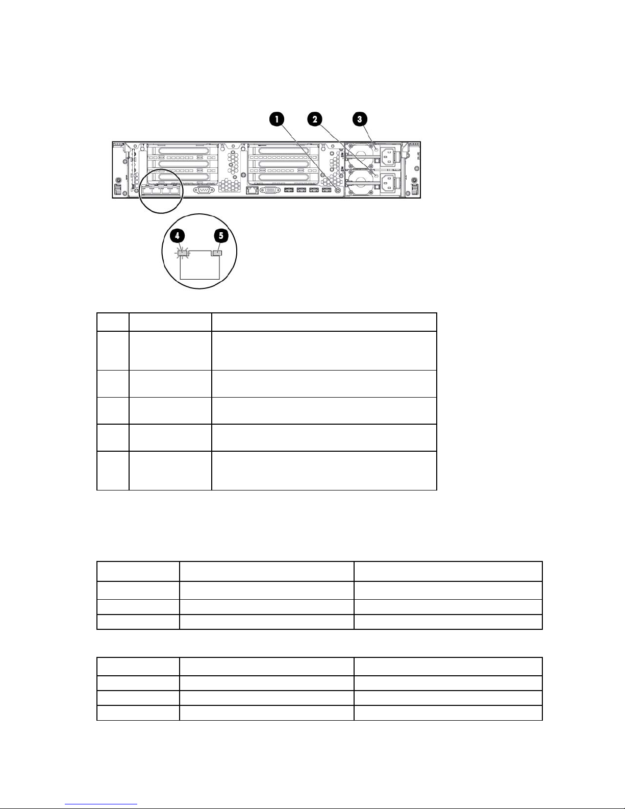
Rear panel LEDs and buttons
Item Description Status
1
2
3
4
5
UID LED/button Off = Deactivated
Solid blue = Activated
Flashing blue = System being managed remotely
Power supply 2
LED
Power supply 1
LED
Off = System is off or power supply has failed.
Solid green = Normal
Off = System is off or power supply has failed.
Solid green = Normal
NIC link LED Off = No network link
Green = Network link
NIC activity LED Off = No network activity
Solid green = Link to network
Flashing green = Network activity
Non-hot-plug PCI riser board slot definitions
• Primary riser cage connector, connected to processor 1 or the southbridge
PCIe 3-slot riser cage* PCIe 2-slot x16 riser cage
1 - FL/FH
2 - HL/FH
3 - HL/FH
• Secondary riser cage connector, connected to processor 2 (Processor 2 must be installed)
4 - FL/FH
5 - HL/FH
6 - HL/FH
PCIe2 or PCIe3** x16 (16,8,4,2,1) —
PCIe2 or PCIe3** x8 (8,4,2,1) —
PCIe2 x8 (4,2,1)† —
PCIe 3-slot riser cage* PCIe 2-slot x16 riser cage
PCIe2 or PCIe3** x16 (16,8,4,2,1) PCIe2 or PCIe3** x16 (16,8,4,2,1)
PCIe2 or PCIe3** x8 (8,4,2,1) PCIe2 or PCIe3** x16 (16,8,4,2,1)
PCIe2 or PCIe3** x8 (8,4,2,1) —
Component identification 14
*The server ships with one PCIe3 riser cage installed in the primary riser cage connector.
**These slots can run 8 GT/s signaling rate in either PCIe2 or PCIe3 mode, depending on the capability of
the installed processor.
†PCIe slot 3 is connected to the southbridge and runs at the Gen2 signaling rate.
Notes:
• "Primary" denotes the riser cage is installed in the primary riser connector.
• "Secondary" denotes the riser cage is installed in the secondary riser connector.
• Installing the riser cages listed in the table above in either the primary or secondary riser connectors
determines the form factor of the PCI cards supported by those riser cages.
• FL/FH denotes full-length, full-height. HL/FH denotes half-length, full-height. LP denotes low profile.
• The PCIe2 x16 riser cage supports a maximum power of 150 W with an HP power cable. This cable
must be used for PCIe card wattages greater than 75 W.
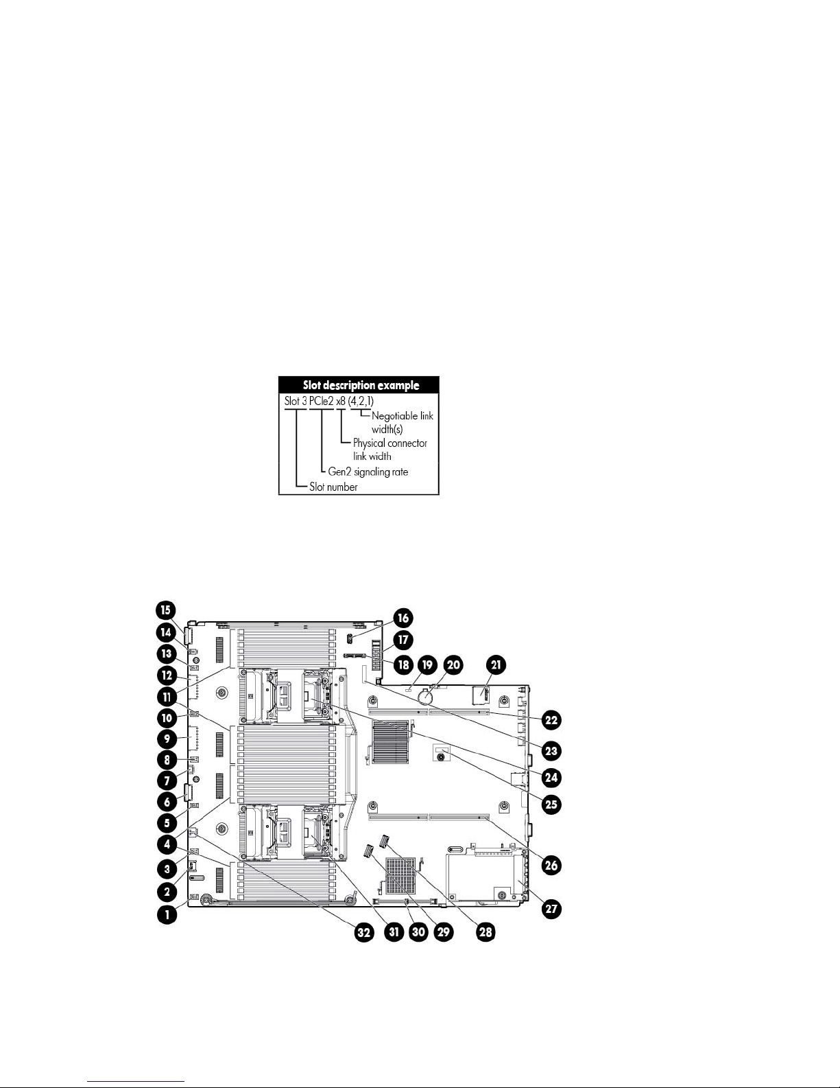
System board components
Component identification 15
Processor 2 socket
SAS connector 2
Item Description
1
Fan connector 6
2
3
4
5
6
7
8
9
10
11
12
13
14
15
16
17
18
19
20
21
22
23
Systems Insight Display connector
Fan connector 5
Processor 1 DIMM slots
Fan connector 4
Front I/O connector
Front USB connector
Fan connector 3
First drive cage, box 2 power connector
Fan connector 2
Processor 2 DIMM slots
Second drive cage, box 1 power connector
Fan connector 1
Discovery services connector
Front video connector
USB connector
Power supply backplane connector
SATA optical drive connector
NMI jumper
System battery
SD card slot
Secondary (processor 2) PCI riser connector
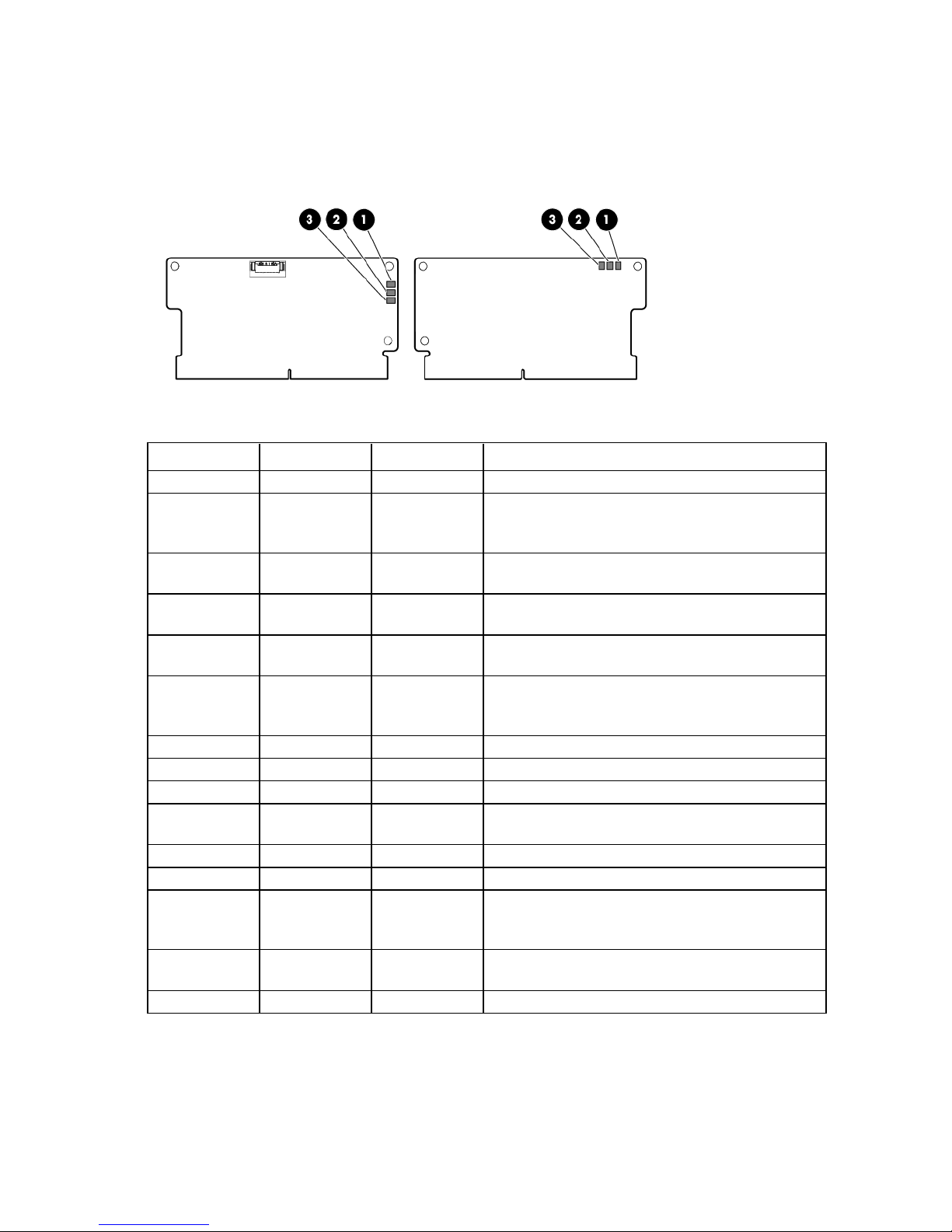
System maintenance switch
24
25
26
27
28
TPM connector
Primary (processor 1) PCI riser connector
FlexibleLOM
SAS connector 1
29
30
31
32
Cache module connector
Processor 1 socket
RDX power connector
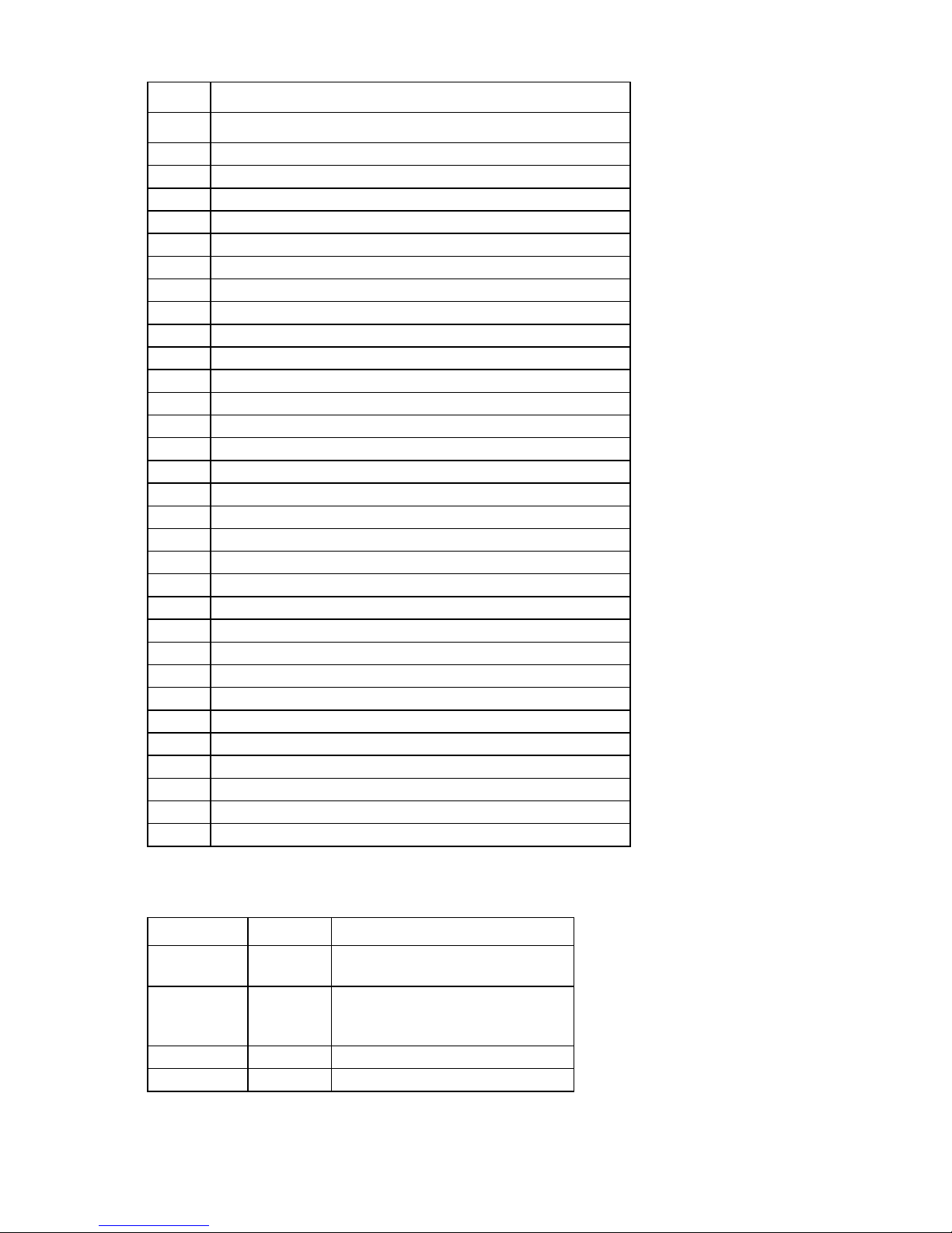
System maintenance switch
Position Default Function
S1
S2
S3
S4
Off Off = HP iLO security is enabled.
Off Off = System configuration can be
Off Reserved
Off Reserved
On = HP iLO security is disabled.
changed.
On = System configuration is locked.
Component identification 16
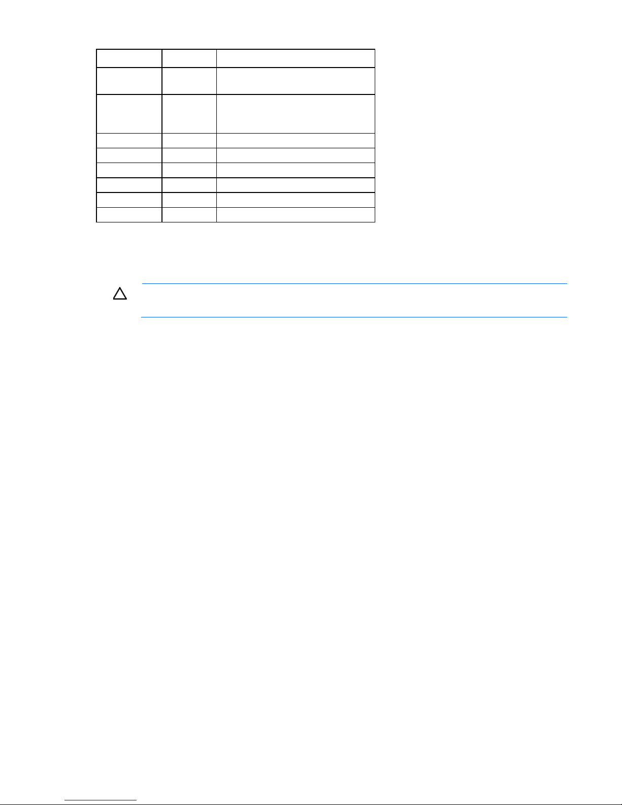
Position Default Function
S5
S6
S7
S8
S9
S10
S11
S12
Off Off = Power-on password is enabled.
On = Power-on password is disabled.
Off Off = No function
On = ROM reads system configuration
as invalid.
— Reserved
— Reserved
— Reserved
— Reserved
— Reserved
— Reserved
To access the redundant ROM, set S1, S5, and S6 to on.
When the system maintenance switch position 6 is set to the On position, the system is prepared to erase all
system configuration settings from both CMOS and NVRAM.
CAUTION: Clearing CMOS and/or NVRAM deletes configuration information. Be sure to
properly configure the server or data loss could occur.
NMI functionality
An NMI crash dump enables administrators to create crash dump files when a system is hung and not
responding to traditional debug mechanisms.
Crash dump log analysis is an essential part of diagnosing reliability problems, such as hangs in operating
systems, device drivers, and applications. Many crashes freeze a system, and the only available action for
administrators is to cycle the system power. Resetting the system erases any information that could support
problem analysis, but the NMI feature preserves that information by performing a memory dump before a
hard reset.
To force the OS to invoke the NMI handler and generate a crash dump log, the administrator can use the iLO
Virtual NMI feature.
For more information, see the white paper on the HP website
(http://h20000.www2.hp.com/bc/docs/support/SupportManual/c00797875/c00797875.pdf).
Component identification 17
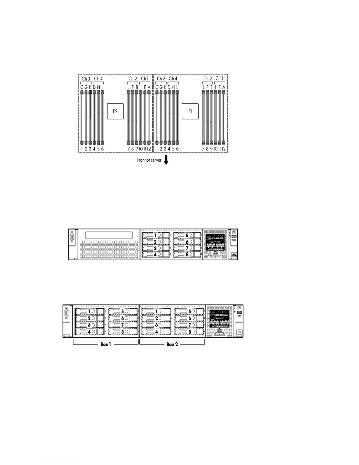
DIMM slot locations
DIMM slots are numbered sequentially (1 through 12) for each processor. The supported AMP modes use the
letter assignments for population guidelines.
SAS and SATA device numbers
• SFF 8-device bay numbering
• Optional SFF 16-device bay numbering
• SFF 25-device bay numbering
Component identification 18
• LFF 8-device bay numbering
• LFF 12-device bay numbering
Hot-plug drive LED definitions
Item LED Status Definition
1
2
Locate Solid blue The drive is being identified by a host application.
Flashing blue The drive carrier firmware is being updated or requires an update.
Activity ring Rotating green Drive activity
Off No drive activity
Component identification 19
Solid amber
The drive has failed.
Item LED Status Definition
3
4
Do not remove Solid white Do not remove the drive. Removing the drive causes one or more of
the logical drives to fail.
Off Removing the drive does not cause a logical drive to fail.
Drive status Solid green The drive is a member of one or more logical drives.
Flashing green The drive is rebuilding or performing a RAID migration, strip size
migration, capacity expansion, or logical drive extension, or is
erasing.
Flashing
amber/green
The drive is a member of one or more logical drives and predicts
the drive will fail.
Flashing amber The drive is not configured and predicts the drive will fail.
Off The drive is not configured by a RAID controller.
PCI riser cage LED
CAUTION: To prevent damage to the server or expansion boards, power down the server and
Status
On = AC power is connected.
Off = AC power is disconnected.
remove all AC power cords before removing or installing the PCI riser cage.
Component identification 20
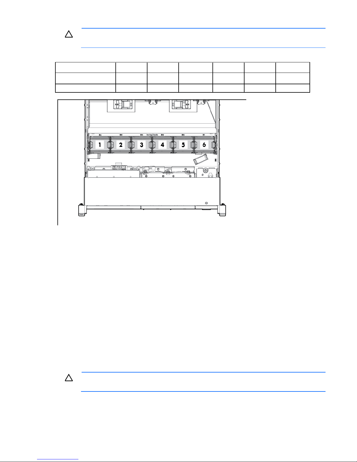
FBWC module LEDs (P222, P420, P421)
The FBWC module has three single-color LEDs (one amber and two green). The LEDs are duplicated on the
reverse side of the cache module to facilitate status viewing.
1 - Amber 2 - Green 3 - Green Interpretation
Off
Off
Off
Off
Off
Off
Off
Off
Flashing 1 Hz
Flashing 1 Hz
Flashing 1 Hz
Flashing 2 Hz
Flashing 2 Hz
On
On
Off Off The cache module is not powered.
Flashing 0.5 Hz Flashing 0.5 Hz The cache microcontroller is executing from within its
boot loader and receiving new flash code from the host
controller.
Flashing 1 Hz Flashing 1 Hz The cache module is powering up, and the capacitor
pack is charging.
Off Flashing 1 Hz The cache module is idle, and the capacitor pack is
charging.
Off On The cache module is idle, and the capacitor pack is
charged.
On On The cache module is idle, the capacitor pack is charged,
and the cache contains data that has not yet been
written to the drives.
Flashing 1 Hz Off A backup is in progress.
On Off The current backup is complete with no errors.
Flashing 1 Hz Off The current backup failed, and data has been lost.
Flashing 1 Hz On A power error occurred during the previous or current
boot. Data may be corrupt.
On Off An overtemperature condition exists.
Flashing 2 Hz Off The capacitor pack is not attached.
Flashing 2 Hz On The capacitor has been charging for 10 minutes, but
has not reached sufficient charge to perform a full
backup.
On Off The current backup is complete, but power fluctuations
occurred during the backup.
On On The cache module microcontroller has failed.
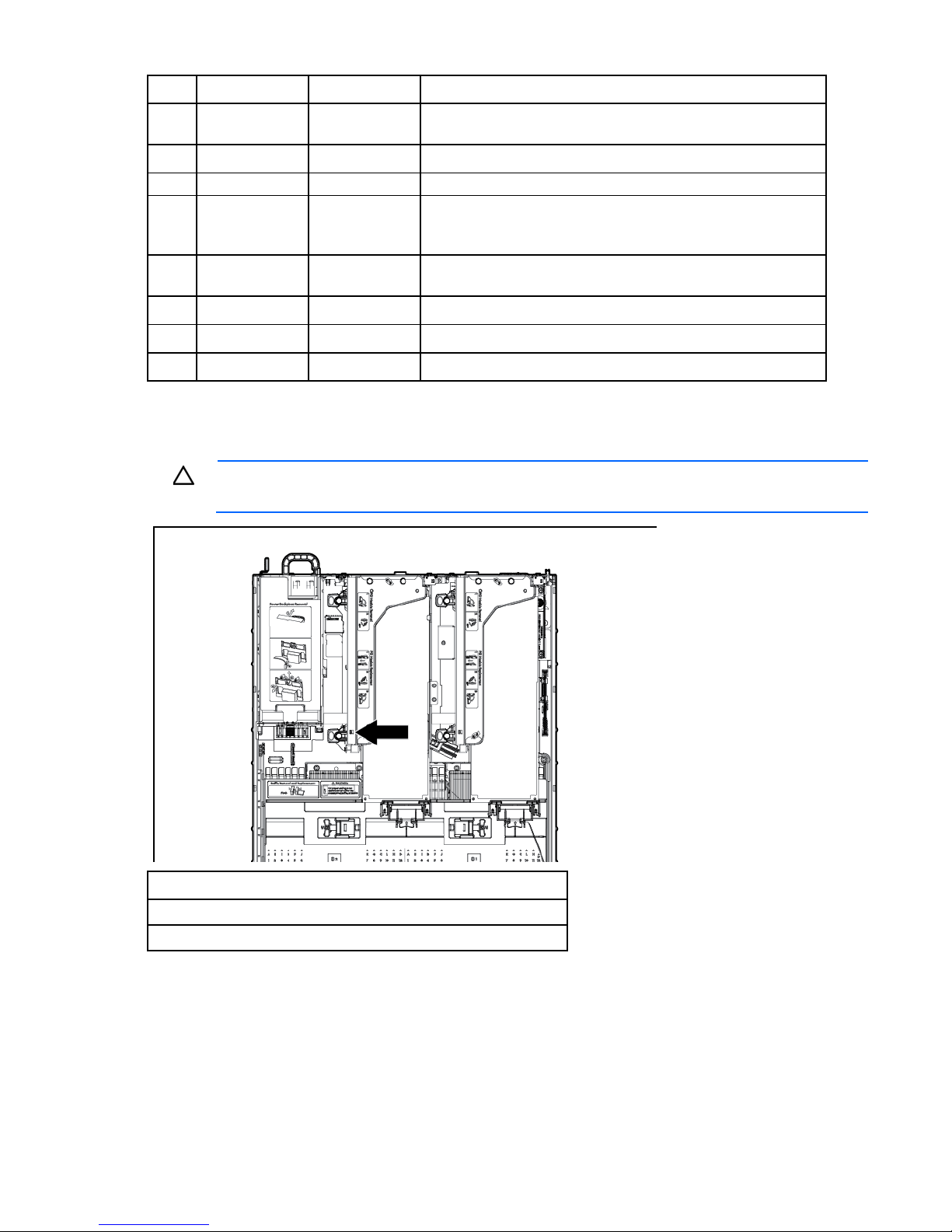
Hot-plug fans
Component identification 21
CAUTION: To avoid damage to server components, fan blanks must be installed in fan bays 1
and 2 in a single-processor configuration.
The only two valid fan configurations are listed in the following table.
Configuration Fan bay 1 Fan bay 2 Fan bay 3 Fan bay 4 Fan bay 5 Fan bay 6
1 processor
Fan blank Fan blank Fan Fan Fan Fan
2 processors
Fan Fan Fan Fan Fan Fan
For a single-processor configuration, four fans and two blanks are required in specific fan bays for
redundancy. A fan failure or missing fan causes a loss of redundancy. A second fan failure or missing fan
causes an orderly shutdown of the server.
Installing more than the required number of fans in a single-processor configuration is not a supported
configuration.
For a dual-processor configuration, six fans are required for redundancy. A fan failure or missing fan causes
a loss of redundancy. A second fan failure or missing fan causes an orderly shutdown of the server.
The server supports variable fan speeds. The fans operate at minimum speed until a temperature change
requires a fan speed increase to cool the server. The server shuts down during the following
temperature-related scenarios:
• At POST and in the OS, HP iLO performs an orderly shutdown if a cautionary temperature level is
detected. If the server hardware detects a critical temperature level before an orderly shutdown occurs,
the server performs an immediate shutdown.
• When the Thermal Shutdown feature is disabled in RBSU, HP iLO does not perform an orderly shutdown
when a cautionary temperature level is detected. Disabling this feature does not disable the server
hardware from performing an immediate shutdown when a critical temperature level is detected.
CAUTION: A thermal event can damage server components when the Thermal Shutdown feature
is disabled in RBSU.
Component identification 22

Operations
Power up the server
To power up the server, press the Power On/Standby button.
Power down the server
Before powering down the server for any upgrade or maintenance procedures, perform a backup of critical
server data and programs.
IMPORTANT: When the server is in standby mode, auxiliary power is still being provided to the
To power down the server, use one of the following methods:
• Press and release the Power On/Standby button.
• Press and hold the Power On/Standby button for more than 4 seconds to force the server to enter
• Use a virtual power button selection through HP iLO.
system.
This method initiates a controlled shutdown of applications and the OS before the server enters standby
mode.
standby mode.
This method forces the server to enter standby mode without properly exiting applications and the OS.
If an application stops responding, you can use this method to force a shutdown.
This method initiates a controlled remote shutdown of applications and the OS before the server enters
standby mode.
Before proceeding, verify the server is in standby mode by observing that the system power LED is amber.
Extend the server from the rack
1. Pull down the quick release levers on each side of the server.
2. Extend the server from the rack.
WARNING: To reduce the risk of personal injury or equipment damage, be sure that the rack is
adequately stabilized before extending a component from the rack.
Operations 23
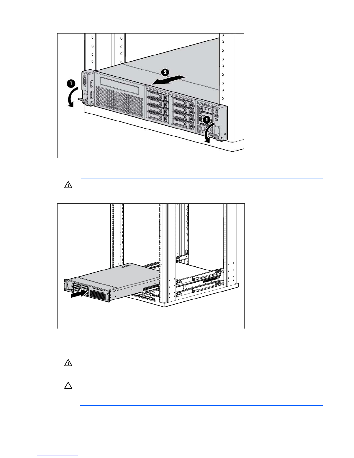
3. After performing the installation or maintenance procedure, slide the server back into the rack, and then
press the server firmly into the rack to secure it in place.
WARNING: To reduce the risk of personal injury, be careful when pressing the server rail-release
latches and sliding the server into the rack. The sliding rails could pinch your fingers.
Remove the access panel
WARNING: To reduce the risk of personal injury from hot surfaces, allow the drives and the
internal system components to cool before touching them.
CAUTION: Do not operate the server for long periods with the access panel open or removed.
Operating the server in this manner results in improper airflow and improper cooling that can
lead to thermal damage.
Operations 24
To remove the component:
1. Power down the server (on page 23).
2. Extend the server from the rack (on page 23).
3. Open or unlock the locking latch, slide the access panel to the rear of the chassis, and remove the
access panel.
Install the access panel
1. Place the access panel on top of the server with the hood latch open. Allow the panel to extend past the
rear of the server approximately 1.25 cm (0.5 in).
2. Push down on the hood latch. The access panel slides to a closed position.
3. Tighten the security screw on the hood latch.
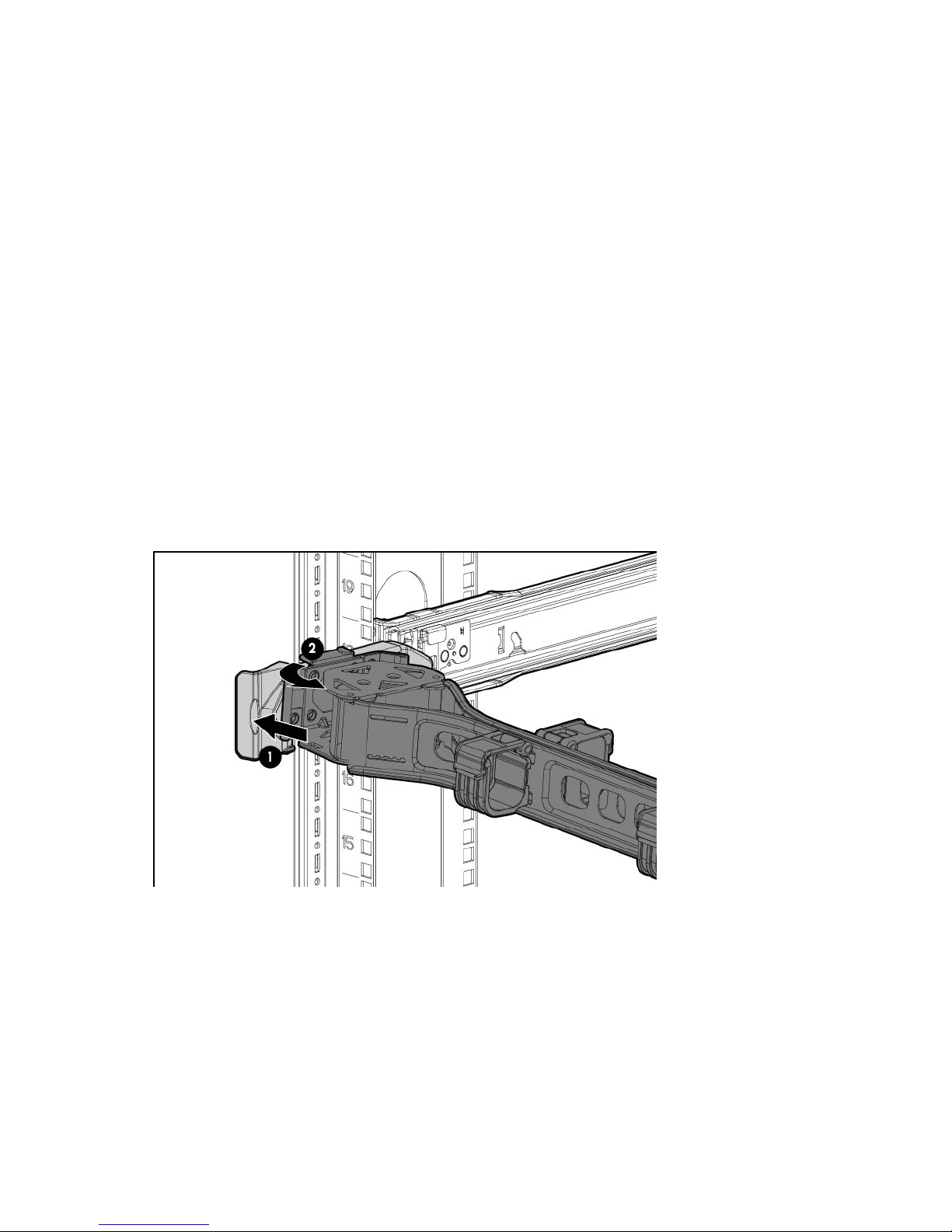
Access the product rear panel
Opening the cable management arm
To access the server rear panel:
1. Release the cable management arm.
Operations 25
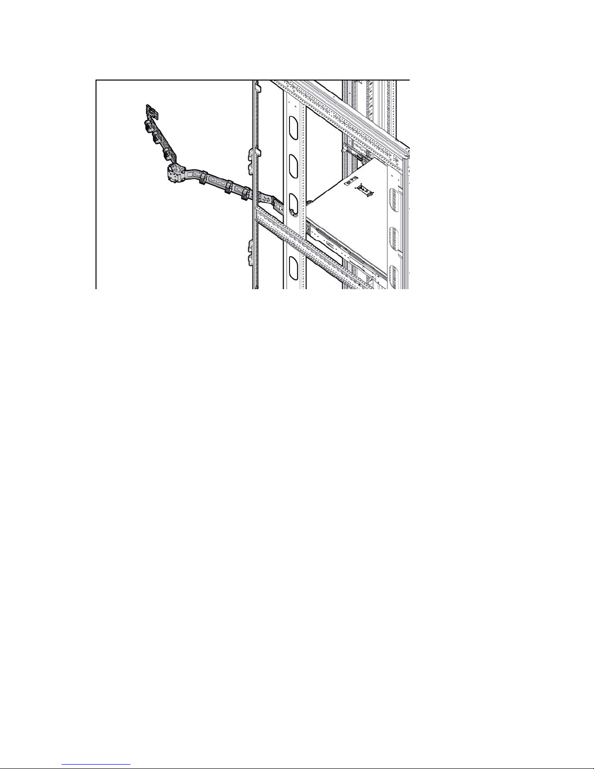
2.
Open the cable management arm. Note that the cable management arm can be right-mounted or
left-mounted.
Remove the hot-plug fan cage
To remove the component:
1. Power down the server (on page 23).
2. Remove all power:
a. Disconnect each power cord from the power source.
b. Disconnect each power cord from the server.
3. Extend ("Extend the server from the rack" on page 23) or remove the server from the rack.
4. Remove the access panel (on page 24).
5. Remove the air baffle (on page 32).
Operations 26
6.
Remove the fan cage.
CAUTION: Do not operate the server for long periods with the access panel open or removed.
Operating the server in this manner results in improper airflow and improper cooling that can
lead to thermal damage.
IMPORTANT: For optimum cooling, install fans in all primary fan locations. For more
information, refer to the fan locations table ("Hot-plug fans" on page 21).
To replace the component, reverse the removal procedure.
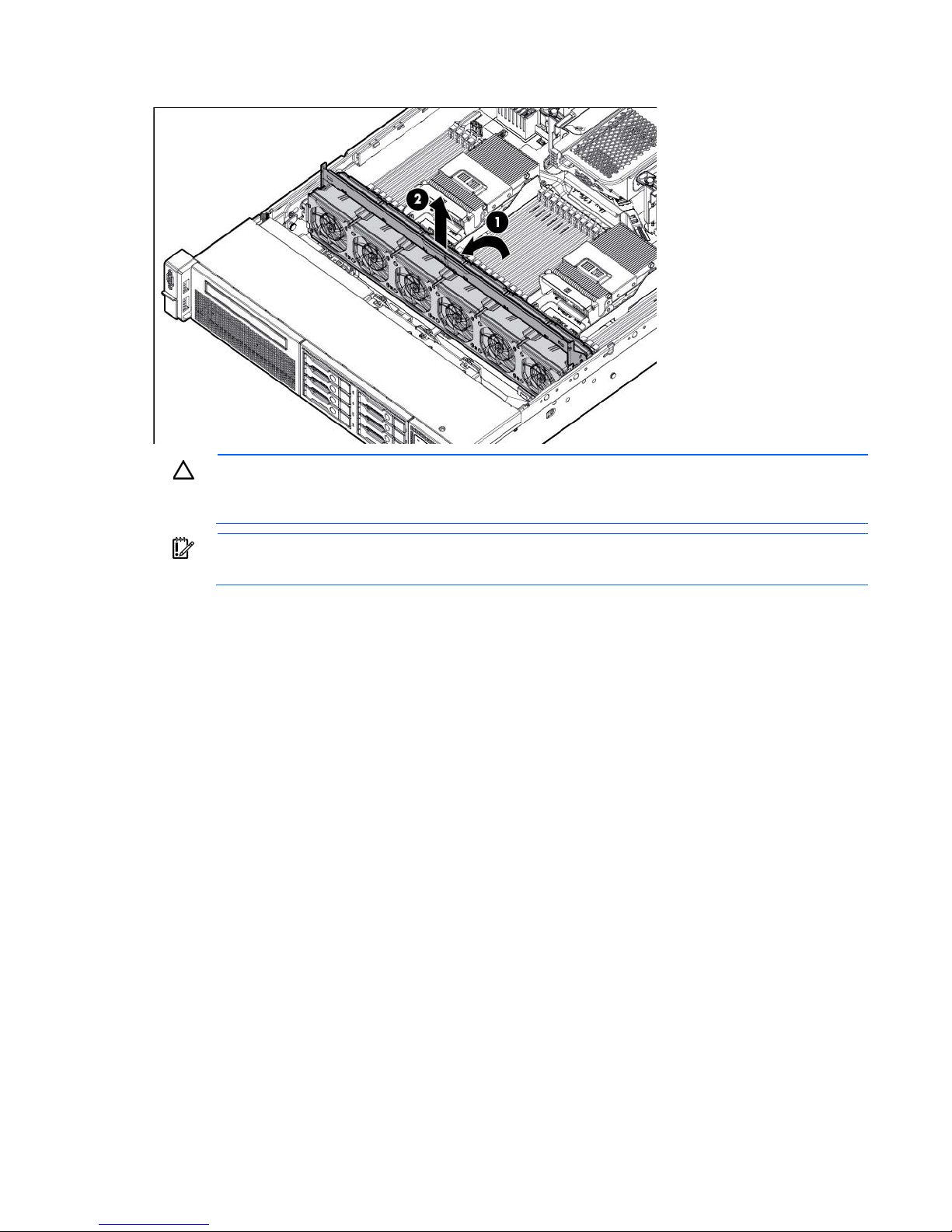
Remove the hot-plug fan
To remove the component:
1. Extend or remove the server from the rack ("Extend the server from the rack" on page 23).
2. Remove the access panel (on page 24).
Operations 27
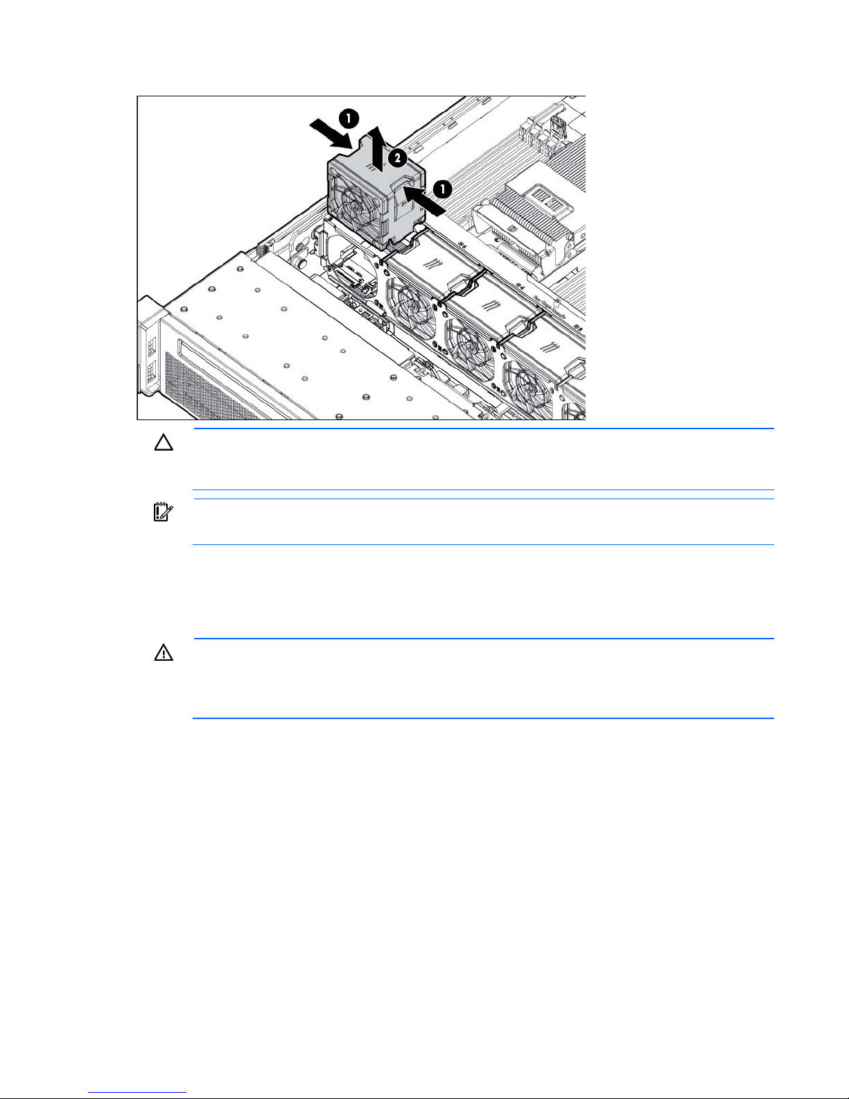
3.
Remove the fan.
CAUTION: Do not operate the server for long periods with the access panel open or removed.
Operating the server in this manner results in improper airflow and improper cooling that can
lead to thermal damage.
IMPORTANT: For optimum cooling, install fans in all primary fan locations. For more
information, refer to the fan locations table ("Hot-plug fans" on page 21).
To replace the component, reverse the removal procedure.
Remove the full-length expansion board
WARNING: To reduce the risk of personal injury, electric shock, or damage to the equipment,
remove the power cord to remove power from the server. The front panel Power On/Standby
button does not completely shut off system power. Portions of the power supply and some internal
To remove the component:
1. Power down the server (on page 23).
2. Remove all power:
circuitry remain active until AC power is removed.
a. Disconnect each power cord from the power source.
b. Disconnect each power cord from the server.
3. Extend ("Extend the server from the rack" on page 23) or remove the server from the rack.
4. Remove the access panel (on page 24).
5. Disconnect any external cables that are connected to the expansion board.
6. Disconnect any internal cables that are connected to the expansion board.
Operations 28
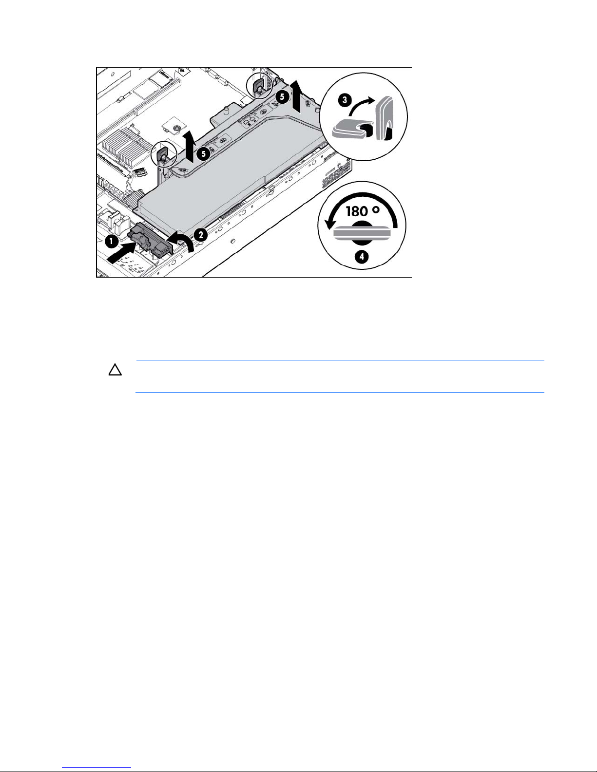
7.
Release the full-length expansion board retainer, and then remove the PCIe riser cage.
8. Remove the full-length expansion board.
To replace the component, reverse the removal procedure.
Remove the PCI riser cage
CAUTION: To prevent damage to the server or expansion boards, power down the server and
1. Power down the server (on page 23).
2. Remove all power:
3. Extend the server from the rack (on page 23).
4. Remove the access panel (on page 24).
remove all AC power cords before removing or installing the PCI riser cage.
a. Disconnect each power cord from the power source.
b. Disconnect each power cord from the server.
Operations 29
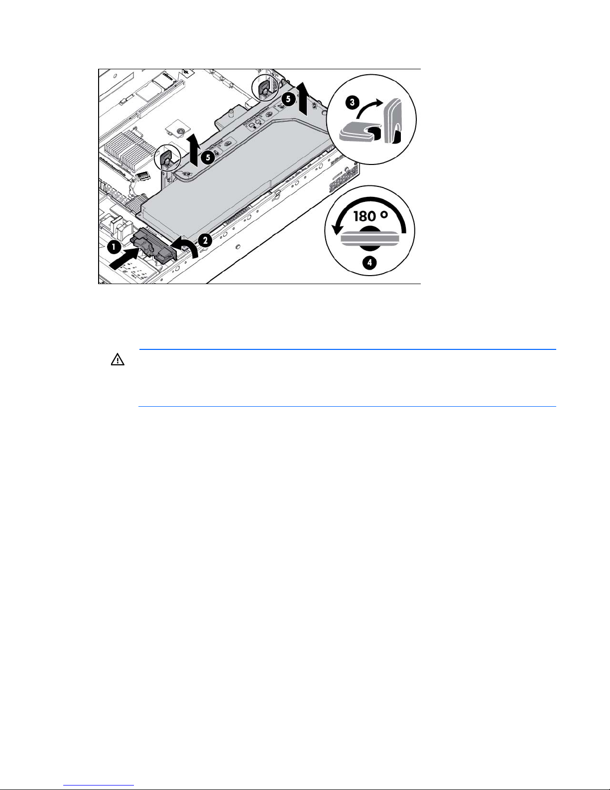
t off system power. Portions of the power supply and some internal
5.
Release the full-length expansion board retainer, and then remove the PCI riser cage.
6. Remove the full-length expansion board.
Install the PCI riser cage
WARNING: To reduce the risk of personal injury, electric shock, or damage to the equipment,
remove the power cord to remove power from the server. The front panel Power On/Standby
button does not completely shu
1. Power down the server (on page 23).
2. Remove all power:
3. Extend the server from the rack (on page 23).
4. Remove the access panel (on page 24).
circuitry remain active until AC power is removed.
a. Disconnect each power cord from the power source.
b. Disconnect each power cord from the server.
Operations 30
 Loading...