

HP ProLiant BL620c G7 User Manual

HP ProLiant BL620c G7 Server Blade
User Guide
Abstract
This document is for the person who installs, administers, and troubleshoots servers and storage systems. HP assumes you are qualified in the
servicing of computer equipment and trained in recognizing hazards in products with hazardous energy levels.
Part Number: 613849-003
April 2011
Edition: 3

© Copyright 2010, 2011 Hewlett-Packard Development Company, L.P.
The information contained herein is subject to change without notice. The only warranties for HP products and services are set forth in the express
warranty statements accompanying such products and services. Nothing herein should be construed as constituting an additional warranty. HP shall
not be liable for technical or editorial errors or omissions contained herein.
Microsoft, Windows, and Windows Server are U.S. registered trademarks of Microsoft Corporation.
Intel, Pentium, and Xeon are registered trademarks of Intel Corporation in the U.S. and other countries.
AMD is a trademark of Advanced Micro Devices, Inc.
Bluetooth is a trademark owned by its proprietor and used by Hewlett-Packard Company under license.
Java is a registered trademark of Oracle and/or its affiliates.

Contents
Component identification ............................................................................................................... 7
Front panel components and LEDs .................................................................................................................. 7
SAS and SATA hard drive LEDs ..................................................................................................................... 8
SAS and SATA hard drive LED combinations .................................................................................................. 8
System board components ............................................................................................................................ 9
System maintenance switch ............................................................................................................... 10
System maintenance switch procedures .............................................................................................. 10
DIMM slot locations .................................................................................................................................... 12
HP c-Class Blade SUV Cable ....................................................................................................................... 12
Operations................................................................................................................................. 14
Power up the server blade ........................................................................................................................... 14
Power down the server blade ...................................................................................................................... 14
Remove the server blade ............................................................................................................................. 15
Remove the access panel ............................................................................................................................ 16
Install the access panel ............................................................................................................................... 16
Remove a hot-plug SAS or SATA hard drive .................................................................................................. 16
Remove the left DIMM baffle ....................................................................................................................... 17
Remove the right DIMM baffle ..................................................................................................................... 18
Remove the front panel/hard drive cage assembly ........................................................................................ 19
Remove the battery pack ............................................................................................................................. 19
Setup ......................................................................................................................................... 21
Overview .................................................................................................................................................. 21
Installing an HP BladeSystem c-Class enclosure ............................................................................................. 21
Preparing the enclosure .................................................................................................................... 21
Installing interconnect modules .......................................................................................................... 26
Connecting to the network................................................................................................................. 27
Installing server blade options ..................................................................................................................... 28
Installing a server blade .............................................................................................................................. 28
Completing the configuration....................................................................................................................... 29
Hardware options installation ....................................................................................................... 30
Introduction ............................................................................................................................................... 30
Processor option......................................................................................................................................... 30
Memory option .......................................................................................................................................... 36
Memory overview ............................................................................................................................ 36
Low Voltage DIMMs ......................................................................................................................... 36
Dual- and quad-rank DIMMs.............................................................................................................. 37
DIMM identification .......................................................................................................................... 37
DIMM installation guidelines ............................................................................................................. 38
Memory subsystem architecture ......................................................................................................... 39
Hemisphere mode ............................................................................................................................ 41
Memory performance optimization .................................................................................................... 42
Memory RAS ................................................................................................................................... 43
Advanced ECC memory population guidelines .................................................................................... 44
Double Device Data Correction ......................................................................................................... 44
Contents 3

HP Memory Quarantine .................................................................................................................... 45
Online Spare memory population guidelines ....................................................................................... 45
Mirrored Memory population guidelines ............................................................................................. 46
Installing DIMMs ........................................................................................................................................ 46
Hot-plug SAS or SATA hard drive option ...................................................................................................... 47
Mezzanine card option .............................................................................................................................. 49
Controller options ....................................................................................................................................... 51
Installing a cache module .................................................................................................................. 51
Installing a capacitor pack ................................................................................................................ 53
HP Trusted Platform Module option .............................................................................................................. 54
Installing the Trusted Platform Module board ....................................................................................... 55
Retaining the recovery key/password ................................................................................................. 56
Enabling the Trusted Platform Module ................................................................................................. 56
Server updates with an HP Trusted Platform Module and BitLocker™ enabled ......................................... 57
Additional TPM features .................................................................................................................... 57
Cabling ..................................................................................................................................... 58
Using the HP c-Class Blade SUV Cable ......................................................................................................... 58
Connecting locally to a server blade with video and USB devices ................................................................... 58
Accessing a server blade with local KVM ........................................................................................... 58
Accessing local media devices .......................................................................................................... 59
Software and configuration utilities ............................................................................................... 61
Server blade deployment tools ..................................................................................................................... 61
HP BladeSystem c-Class Advanced management ................................................................................. 61
Network-based PXE deployment ........................................................................................................ 61
Deployment methods ........................................................................................................................ 63
Configuration tools ..................................................................................................................................... 67
SmartStart software .......................................................................................................................... 67
HP ROM-Based Setup Utility .............................................................................................................. 68
Array Configuration Utility ................................................................................................................ 71
Option ROM Configuration for Arrays................................................................................................ 71
Re-entering the server serial number and product ID ............................................................................. 72
Management tools...................................................................................................................................... 72
Automatic Server Recovery ................................................................................................................ 72
ROMPaq utility ................................................................................................................................. 73
iLO 3 Standard Blade Edition technology ........................................................................................... 73
Erase Utility ..................................................................................................................................... 73
Redundant ROM support ................................................................................................................... 74
USB support and functionality ............................................................................................................ 74
Internal SD support ........................................................................................................................... 75
Diagnostic tools ......................................................................................................................................... 75
HP Insight Diagnostics ...................................................................................................................... 75
HP Insight Diagnostics survey functionality .......................................................................................... 75
Integrated Management Log .............................................................................................................. 75
Remote support and analysis tools ............................................................................................................... 76
HP Insight Remote Support software ................................................................................................... 76
Keeping the system current .......................................................................................................................... 77
Drivers ............................................................................................................................................ 77
Version control ................................................................................................................................. 77
ProLiant Support Packs ...................................................................................................................... 77
Operating System Version Support ..................................................................................................... 78
Firmware ......................................................................................................................................... 78
HP Smart Update Manager ............................................................................................................... 78
Contents 4

Change control and proactive notification .......................................................................................... 79
Care Pack ....................................................................................................................................... 79
Troubleshooting .......................................................................................................................... 80
Troubleshooting resources ........................................................................................................................... 80
Pre-diagnostic steps .................................................................................................................................... 80
Important safety information .............................................................................................................. 80
Symptom information ........................................................................................................................ 82
Prepare the server for diagnosis ......................................................................................................... 82
Loose connections ...................................................................................................................................... 84
Service notifications .................................................................................................................................... 84
Server health LEDs ...................................................................................................................................... 84
Troubleshooting flowcharts .......................................................................................................................... 84
Start diagnosis flowchart ................................................................................................................... 85
General diagnosis flowchart .............................................................................................................. 86
Server blade power-on problems flowchart ......................................................................................... 88
POST problems flowchart .................................................................................................................. 90
OS boot problems flowchart .............................................................................................................. 92
Server fault indications flowchart ....................................................................................................... 94
POST error messages and beep codes ......................................................................................................... 96
Battery replacement .................................................................................................................... 98
Regulatory compliance notices ..................................................................................................... 99
Regulatory compliance identification numbers ............................................................................................... 99
Federal Communications Commission notice ................................................................................................. 99
FCC rating label .............................................................................................................................. 99
Class A equipment ........................................................................................................................... 99
Class B equipment ............................................................................................................................ 99
Declaration of conformity for products marked with the FCC logo, United States only ...................................... 100
Modifications ........................................................................................................................................... 100
Cables .................................................................................................................................................... 100
Canadian notice (Avis Canadien) .............................................................................................................. 100
European Union regulatory notice .............................................................................................................. 101
Disposal of waste equipment by users in private households in the European Union ........................................ 101
Japanese notice ....................................................................................................................................... 102
BSMI notice ............................................................................................................................................. 102
Korean notice .......................................................................................................................................... 102
Chinese notice ......................................................................................................................................... 103
Laser compliance ..................................................................................................................................... 103
Battery replacement notice ........................................................................................................................ 103
Taiwan battery recycling notice ................................................................................................................. 104
Wireless devices ...................................................................................................................................... 104
Brazilian notices ............................................................................................................................ 104
Canadian notices ........................................................................................................................... 104
Japanese notices ............................................................................................................................ 105
Taiwan notices ............................................................................................................................... 105
Electrostatic discharge ............................................................................................................... 106
Preventing electrostatic discharge .............................................................................................................. 106
Grounding methods to prevent electrostatic discharge .................................................................................. 106
Specifications ........................................................................................................................... 107
Environmental specifications ...................................................................................................................... 107
Server blade specifications ........................................................................................................................ 107
Contents 5

Technical support ...................................................................................................................... 108
Before you contact HP .............................................................................................................................. 108
HP contact information .............................................................................................................................. 108
Customer Self Repair ................................................................................................................................ 108
Acronyms and abbreviations ...................................................................................................... 116
Index ....................................................................................................................................... 119
Contents 6
Component identification
3
10
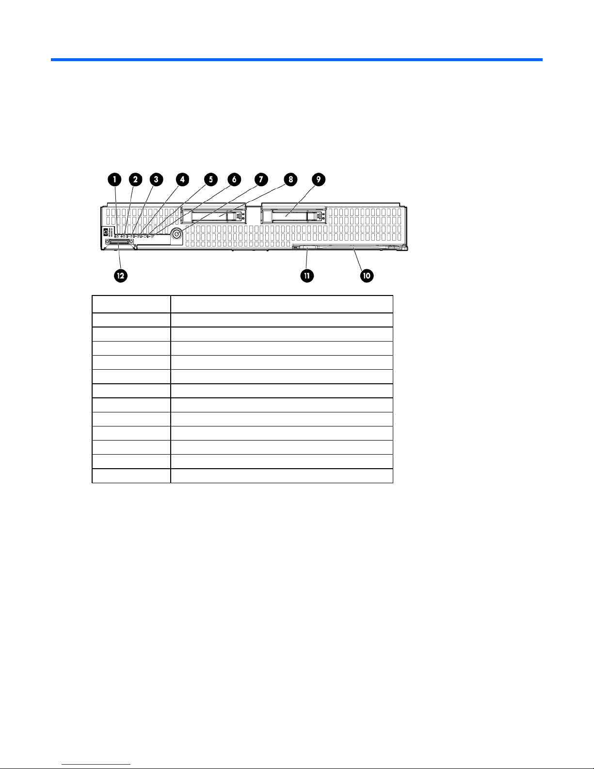
Front panel components and LEDs
Item Description
1
2
4
5
6
7
8
9
11
12
UID LED
Health LED
Flex 1 LED
Flex 2 LED
Flex 3 LED
Flex 4 LED
Power On/Standby button and system power LED
Hard drive bay 1
Hard drive bay 2
Server release lever
Server release lever button
Local I/O connector
Component identification 7
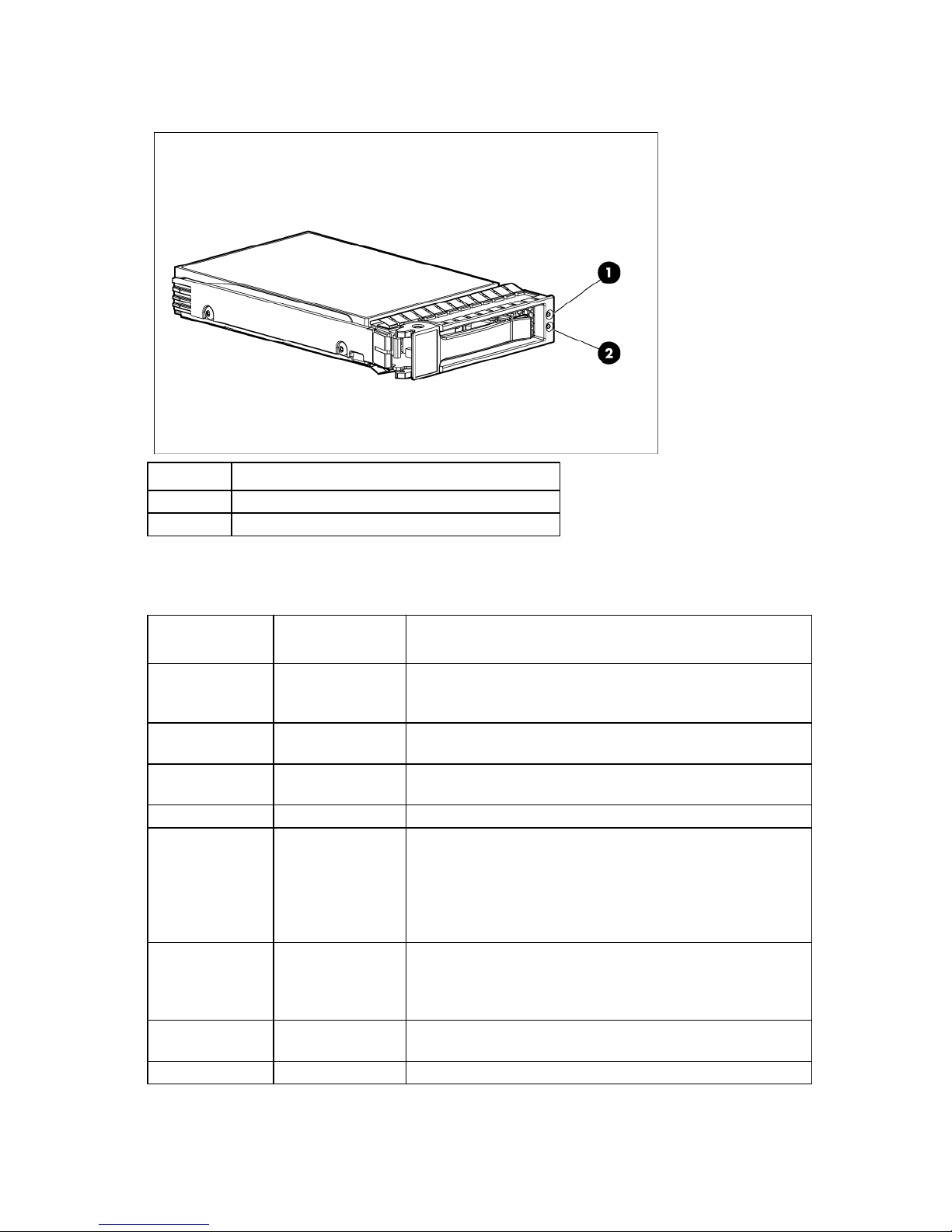
SAS and SATA hard drive LEDs
The drive is active, but a predictive failure alert has been received
Item Description
1
2
Fault/UID LED (amber/blue)
Online LED (green)
SAS and SATA hard drive LED combinations
Online/activity
LED (green)
On, off, or flashing
On, off, or flashing
On
On
Flashing regularly
(1 Hz)
Flashing regularly
(1 Hz)
Flashing irregularly
Flashing irregularly
Fault/UID LED
(amber/blue)
Alternating amber
and blue
Steadily blue The drive is operating normally, and it has been selected by a
Amber, flashing
regularly (1 Hz)
Off The drive is online, but it is not active currently.
Amber, flashing
regularly (1 Hz)
Off Do not remove the drive. Removing a drive may terminate the
Amber, flashing
regularly (1 Hz)
Off The drive is active, and it is operating normally.
Interpretation
The drive has failed, or a predictive failure alert has been received
for this drive; it also has been selected by a management
application.
management application.
A predictive failure alert has been received for this drive.
Replace the drive as soon as possible.
Do not remove the drive. Removing a drive may terminate the
current operation and cause data loss.
The drive is part of an array that is undergoing capacity expansion
or stripe migration, but a predictive failure alert has been received
for this drive. To minimize the risk of data loss, do not replace the
drive until the expansion or migration is complete.
current operation and cause data loss.
The drive is rebuilding, erasing, or it is part of an array that is
undergoing capacity expansion or stripe migration.
for this drive. Replace the drive as soon as possible.
Component identification 8
A predictive failure alert has been received for this drive. Replace
5
12
Online/activity
LED (green)
Off
Fault/UID LED
(amber/blue)
Steadily amber A critical fault condition has been identified for this drive, and the
Interpretation
controller has placed it offline. Replace the drive as soon as
possible.
Off
Off
Amber, flashing
regularly (1 Hz)
the drive as soon as possible.
Off The drive is offline, a spare, or not configured as part of an array.
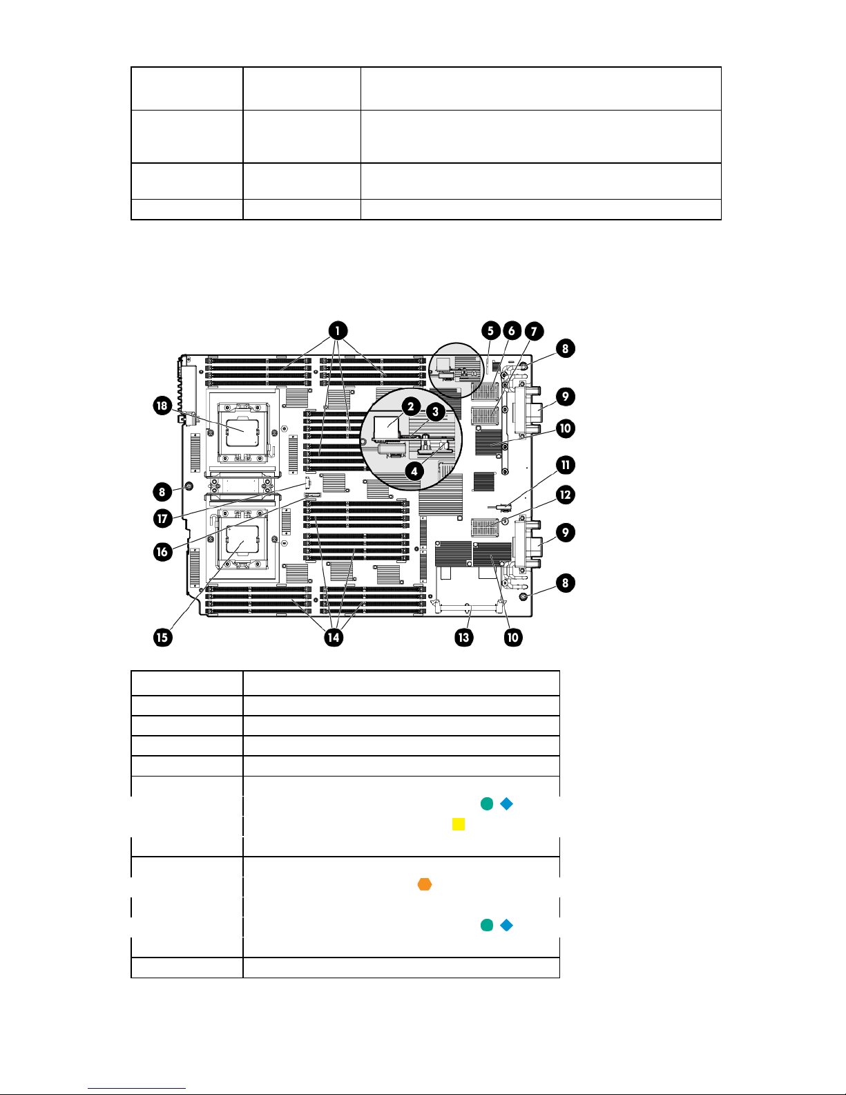
System board components
Item Description
1
2
3
4
6
7
8
9
10
11
13
14
Processor 2 DIMM slots (16)
USB connector
Micro SDHC card connector
TPM connector
System maintenance switch
Mezzanine connector 2 (Type I or Type II)
Mezzanine connector 1 (Type I only)
System board thumbscrews (3)
Enclosure connectors (2)
Embedded FlexFabric adapter
SAS/SATA signal connector
Mezzanine connector 3 (Type I or Type II)
Cache module connector
Processor 1 DIMM slots (16)
Component identification 9
Item Description
17
15
16
18
The symbols correspond to the symbols located on the interconnect bays. For more information, see the
HP ProLiant BL620c G7 Server Blade Installation Instructions that ship with the server blade.
Processor 1
System battery
SAS/SATA backplane power connector
Processor 2
System maintenance switch
The system maintenance switch (SW1) is an eight-position switch that is used for system configuration. The
default position for all eight positions is Off.
Position Description Function
S1
S2
S3
S4
S5
S6
S7
S8
iLO 3 security Off = iLO 3 security is enabled.
On = iLO 3 security is disabled.
Configuration
lock
Off = System configuration can be
changed.
On = System configuration is
locked.
Reserved Reserved
Reserved Reserved
Password
protection
override
Invalidate
configuration
Off = No function
On = Clears power-on password
and administrator password
Off = Normal
On = Clears NVRAM
Reserved Reserved
Reserved Reserved
System maintenance switch procedures
When you perform troubleshooting steps, this guide may instruct you to perform the following procedures:
• Clear the system configuration ("Clearing the system configuration" on page 10).
• Access the redundant ROM ("Accessing the redundant ROM" on page 11).
Clearing the system configuration
To complete these procedures, you must change physical settings on the system maintenance switch.
RBSU can be used to restore the factory default configuration. For more information, see "HP ROM-Based
Setup Utility (on page 68)." If the system is unable to boot into RBSU, use the following steps to clear the
system configuration:
1. Power down the server blade (on page 14).
2. Remove the server blade (on page 15).
3. Remove the access panel (on page 16).
4. Change position 6 of the system maintenance switch to on.
Component identification 10

5.
Install the access panel (on page 16).
6. Install the server blade in the enclosure and power up the server blade.
7. Wait for the POST message that prompts you to change the switch setting:
Maintenance switch detected in the "On" position.
Power off the server and turn switch to the "Off" position.
8. Repeat steps 1 through 3.
9. Change position 6 of the system maintenance switch to off.
10. Repeat steps 5 and 6.
IMPORTANT: When the server blade boots after NVRAM is cleared, a delay of up to 2 minutes
is normal. During this delay, the system appears non-functional. Do not attempt any procedures
during the delay.
Accessing the redundant ROM
If the system ROM is corrupted, the system automatically switches to the redundant ROM in most cases. If the
system does not automatically switch to the redundant ROM, perform the following steps:
1. Power down the server blade (on page 14).
2. Remove the server blade (on page 15).
3. Remove the access panel (on page 16).
4. Change positions 1, 5, and 6 of the system maintenance switch to on.
5. Install the access panel (on page 16).
6. Install the server blade in the enclosure and power up the server blade.
7. After the system beeps, repeat steps 1 through 3.
8. Change positions 1, 5, and 6 of system maintenance switch to off.
9. Repeat steps 5 and 6.
If both the current and backup versions of the ROM are corrupt, return the system board for a service
replacement.
To switch to the backup ROM when the System ROM is not corrupt, use RBSU.
Component identification 11
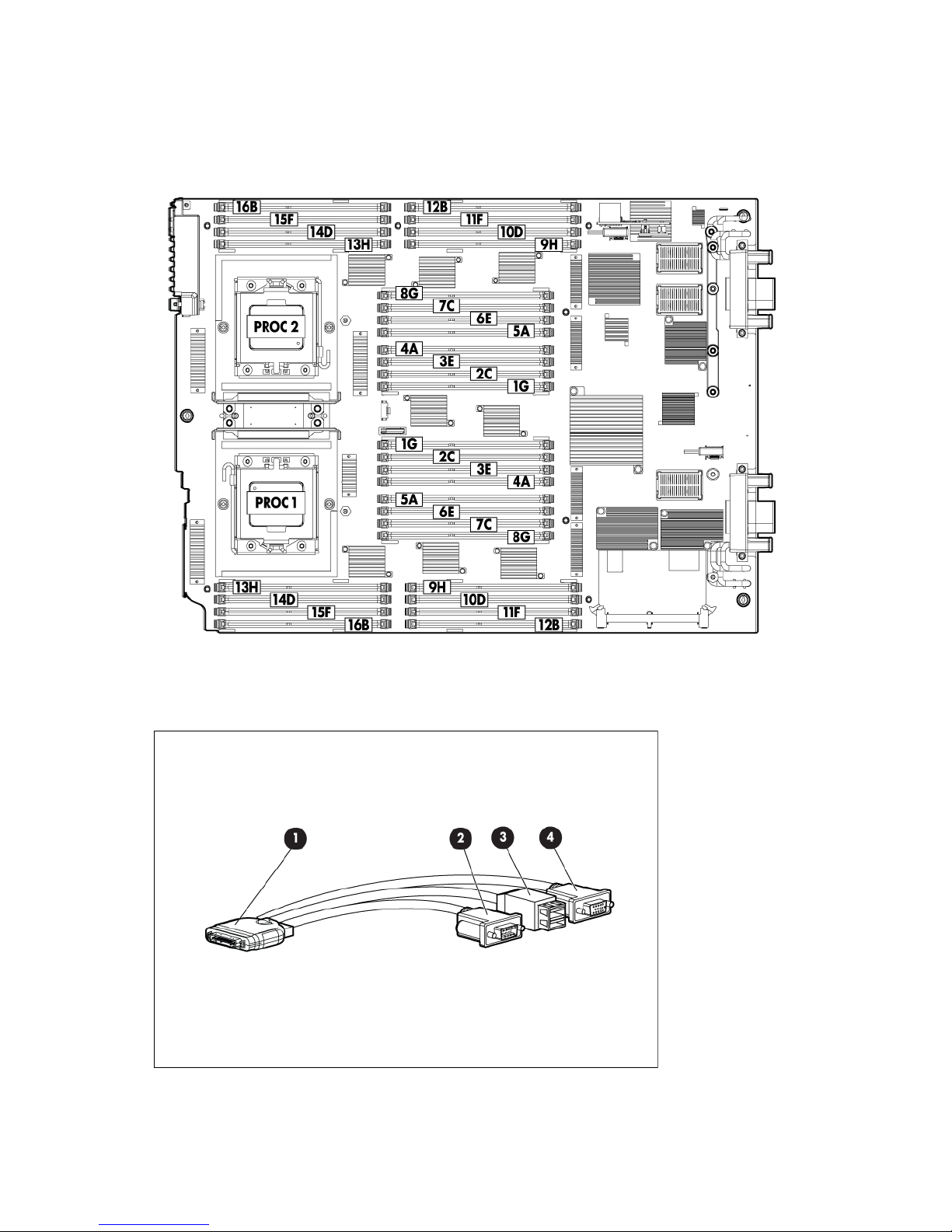
DIMM slot locations
DIMM slots are numbered sequentially (1 through 16) for each processor. The supported AMP modes use the
letter assignments for population guidelines.
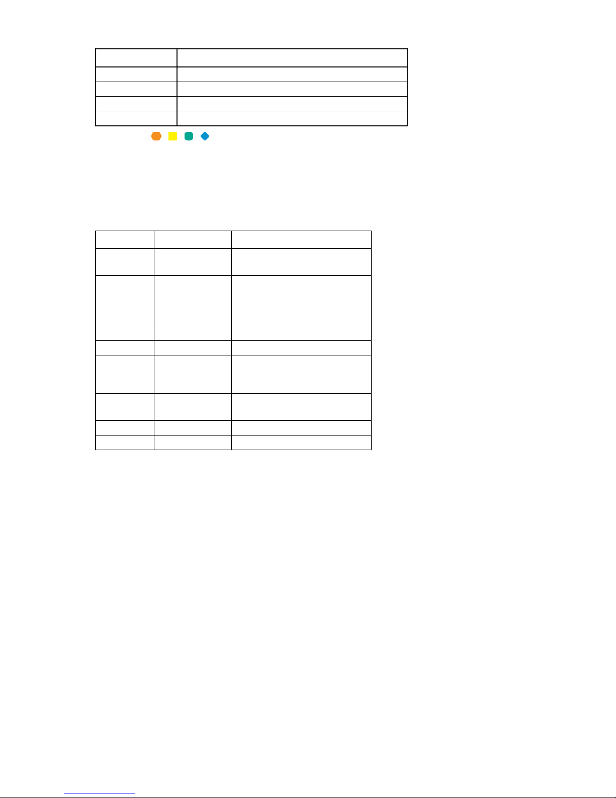
HP c-Class Blade SUV Cable
Component identification 12

Item Connector Description
1
2
3
4
Server blade For connecting to the SUV connector on the
server blade front panel
Video For connecting a video monitor
USB For connecting up to two USB devices
Serial For trained personnel to connect a null modem
serial cable and perform advanced diagnostic
procedures
Component identification 13

Operations
Power up the server blade
The Onboard Administrator initiates an automatic power-up sequence when the server blade is installed. If
the default setting is changed, use one of the following methods to power up the server blade:
• Use a virtual power button selection through iLO 3.
• Press and release the Power On/Standby button.
When the server blade goes from the standby mode to the full power mode, the system power LED changes
from amber to green.
For more information about the Onboard Administrator, see the enclosure setup and installation guide on the
HP website (http://www.hp.com/support).
For more information about iLO 3, see "iLO 3 Standard Blade Edition technology (on page 73)."
Power down the server blade
Before powering down the server blade for any upgrade or maintenance procedures, perform a backup of
critical server data and programs.
Depending on the Onboard Administrator configuration, use one of the following methods to power down
the server blade:
• Use a virtual power button selection through iLO 3.
This method initiates a controlled remote shutdown of applications and the OS before the server blade
enters standby mode.
• Press and release the Power On/Standby button.
This method initiates a controlled shutdown of applications and the OS before the server blade enters
standby mode.
• Press and hold the Power On/Standby button for more than 4 seconds to force the server blade to enter
standby mode.
This method forces the server blade to enter standby mode without properly exiting applications and the
OS. It provides an emergency shutdown method if an application stops responding.
• Execute one of the following commands using the Onboard Administrator CLI:
poweroff server [bay number]
or
poweroff server [bay number] force
The first command initiates a controlled shutdown of applications and the OS before the server blade
enters standby mode. The second form of the command forces the server blade to enter standby mode
without exiting applications and the OS. This emergency method forces a shutdown if an application
stops responding.
• Use the Onboard Administrator GUI to initiate a shutdown:
Operations 14
a.
Select the Enclosure Information tab, and then select the Overall checkbox in the Device Bays item.
b. Initiate a shutdown from the Virtual Power menu:
— Select Momentary Press to initiate a controlled shutdown of applications and the OS.
— Select Press and Hold to initiate an emergency shutdown of applications and the OS.
IMPORTANT: When the server blade is in standby mode, auxiliary power is still being provided.
To remove all power from the server blade, remove the server blade from the enclosure.
After initiating a virtual power down command, be sure that the server blade is in standby mode by
observing that the system power LED is amber.
Remove the server blade
CAUTION: Do not use the server blade release lever to lift or carry the server blade. Always
support the weight of the server blade by handling the chassis directly. Improper use can damage
1. Identify the proper server blade.
2. Power down the server blade (on page 14).
3. Remove the server blade.
the release lever and the server blade.
4. Place the server blade on a flat, level work surface.
WARNING: To reduce the risk of personal injury from hot surfaces, allow the drives and the
internal system components to cool before touching them.
CAUTION: To prevent damage to electrical components, properly ground the server blade
before beginning any installation procedure. Improper grounding can cause ESD.
Operations 15

Remove the access panel
To prevent improper cooling and thermal damage, do not operate the server blade
To remove the component:
1. Power down the server blade (on page 14).
2. Remove the server blade (on page 15).
3. Press the access panel release button, and then slide the access panel to the rear.
4. Remove the access panel.
WARNING: To reduce the risk of personal injury from hot surfaces, allow the drives and the
internal system components to cool before touching them.
CAUTION: To prevent damage to electrical components, properly ground the server blade
before beginning any installation procedure. Improper grounding can cause ESD.
Install the access panel
1. Place the access panel on top of the server blade. Allow the panel to extend past the rear of the server
blade approximately 1 cm (0.25 in).
2. Slide the access panel to the closed position.
Remove a hot-plug SAS or SATA hard drive
CAUTION:
or the enclosure unless all hard drive and device bays are populated with either a component or
1. Determine the status of the hard drive from the hot-plug SAS hard drive LED combinations ("SAS and
2. Back up all server data.
a blank.
SATA hard drive LED combinations" on page 8).
Operations 16
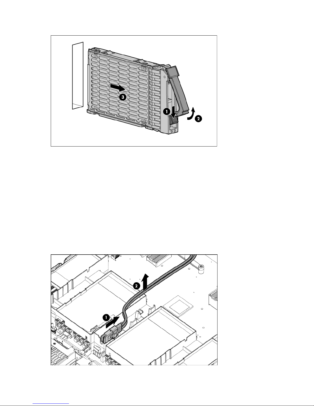
3.
Remove the hard drive.
To replace the component, reverse the removal procedure.
Remove the left DIMM baffle
To remove the component:
1. Power down the server blade (on page 14).
2. Remove the server blade (on page 15).
3. Remove the access panel (on page 16).
4. If installed, remove the battery pack (on page 19).
You do not need to disconnect the cable from the battery.
5. Disconnect the SAS/SATA signal cable from the SAS backplane.
6. Unroute the SAS/SATA cable.
Operations 17
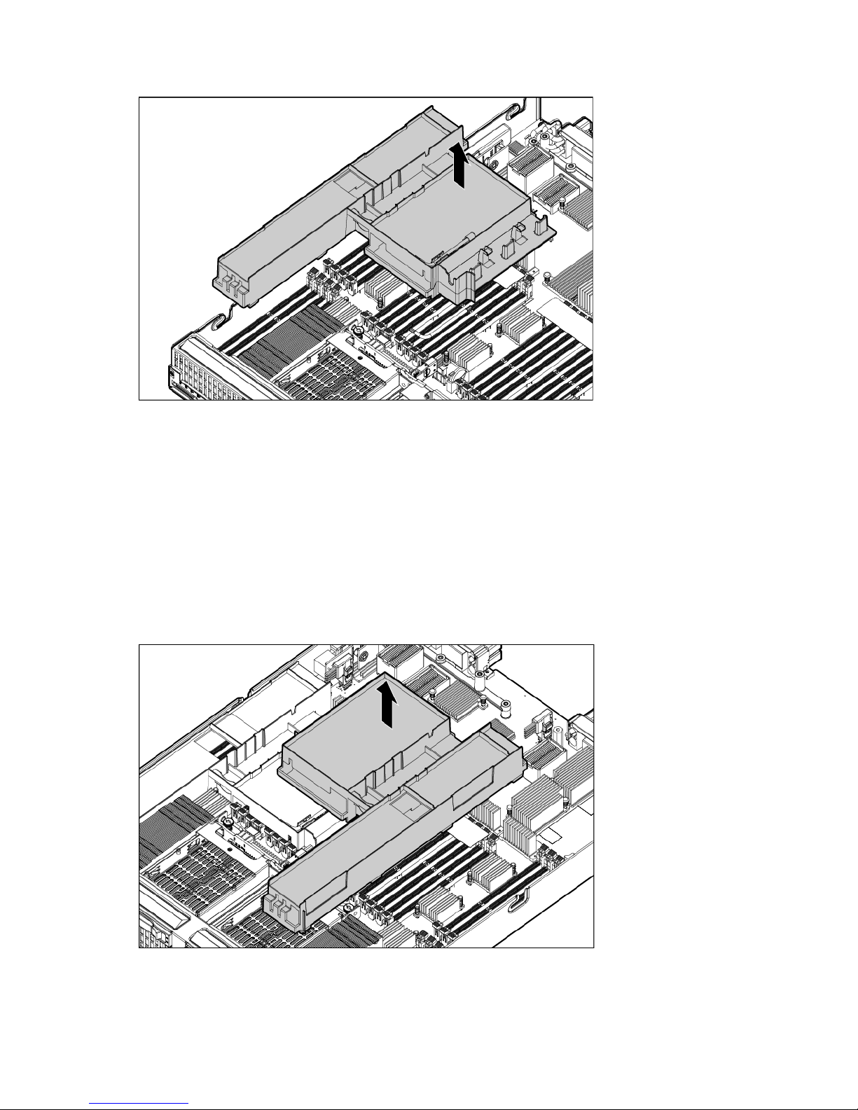
7.
Remove the left DIMM baffle.
Remove the right DIMM baffle
To remove the component:
1. Power down the server blade (on page 14).
2. Remove the server blade (on page 15).
3. Remove the access panel (on page 16).
4. If installed, remove the battery pack (on page 19).
You do not need to disconnect the cable from the battery.
5. Remove the right DIMM baffle.
Operations 18
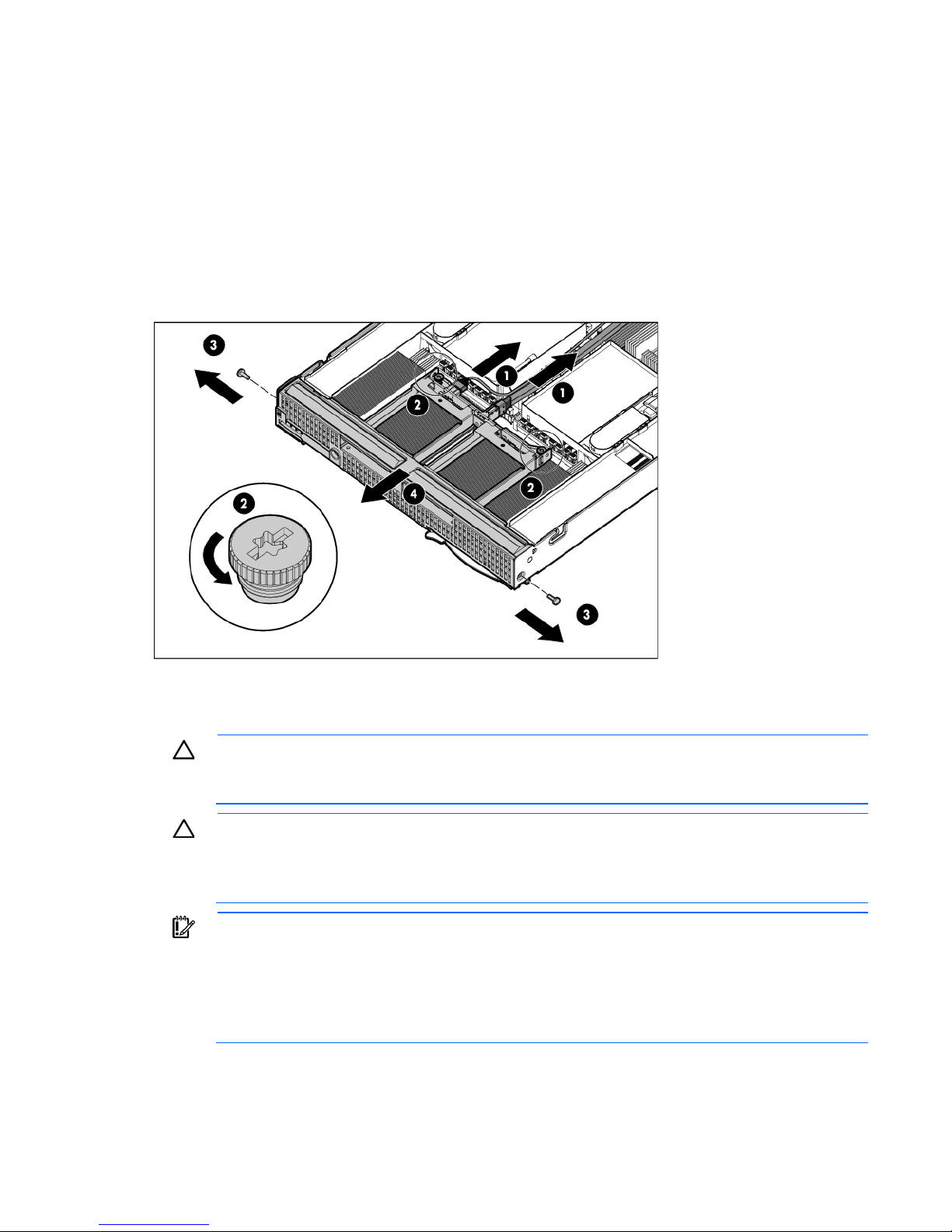
Remove the front panel/hard drive cage assembly
tion is necessary on your part. The internal circuitry automatically
To remove the component:
1. Power down the server blade (on page 14).
2. Remove the server blade (on page 15).
3. Remove the access panel (on page 16).
4. Disconnect the signal cable and the power cable from the SAS backplane.
5. Loosen the thumbscrews.
6. Remove the front panel/hard drive cage assembly.
Remove the battery pack
CAUTION: To prevent a server blade malfunction or damage to the equipment, do not add or
remove the battery pack while an array capacity expansion, RAID level migration, or stripe size
To remove the component:
1. Power down the server blade (on page 14).
migration is in progress.
CAUTION: After the server blade is powered down, wait 15 seconds and then check the amber
LED before unplugging the cable from the cache module. If the amber LED blinks after 15
seconds, do not remove the cable from the cache module. The cache module is backing up data,
and data is lost if the cable is detached.
IMPORTANT: The battery pack might have a low charge when installed. In this case, a POST
error message is displayed when the server blade is powered up, indicating that the battery pack
is temporarily disabled. No ac
recharges the batteries and enables the battery pack. This process might take up to four hours.
During this time, the cache module functions properly, but without the performance advantage of
the battery pack.
Operations 19
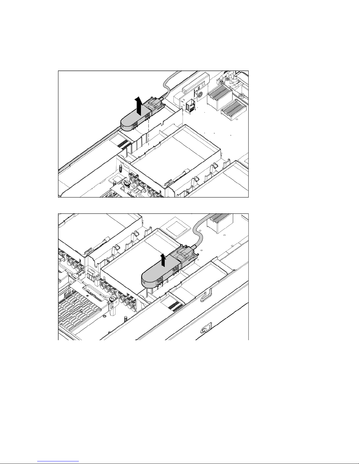
2.
Remove the server blade (on page 15).
3. Remove the access panel (on page 16).
4. Do one of the following:
o Remove the battery pack from the left DIMM baffle.
o Remove the battery pack from the right DIMM baffle.
Operations 20

Setup
To prevent improper cooling and thermal damage, do not operate the server blade
Overview
Installation of a server blade requires the following steps:
1. Install and configure an HP BladeSystem c-Class enclosure.
2. Install any server blade options.
3. Install interconnect modules in the enclosure.
4. Connect the interconnect modules to the network.
5. Install a server blade.
6. Complete the server blade configuration.
Installing an HP BladeSystem c-Class enclosure
Before performing any server blade-specific procedures, install an HP BladeSystem c-Class enclosure.
The most current documentation for server blades and other HP BladeSystem components is available at the
HP website (http://www.hp.com/go/bladesystem/documentation).
Documentation is also available in the following locations:
• Documentation CD that ships with the enclosure
Preparing the enclosure
• HP Business Support Center website (http://www.hp.com/support)
HP BladeSystem enclosures ship with device bay dividers to support half-height devices. To install a full-height
device, remove the blanks and the corresponding device bay divider.
CAUTION:
or the enclosure unless all hard drive and device bays are populated with either a component or
a blank.
IMPORTANT: For optimal cooling and system performance, configure the c7000 enclosure with
ten fans and configure the c3000 enclosure with six fans.
Setup 21
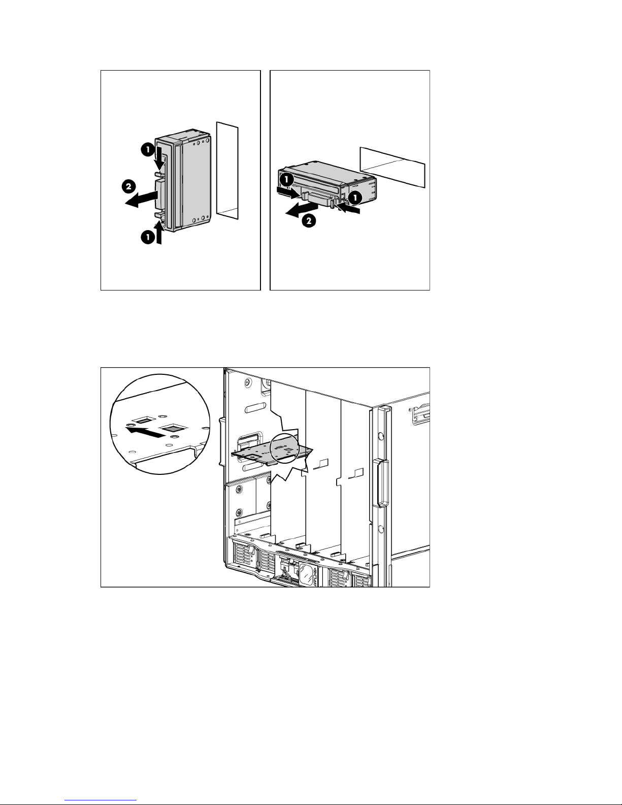
1.
Remove the device bay blank.
2. Remove the three adjacent blanks.
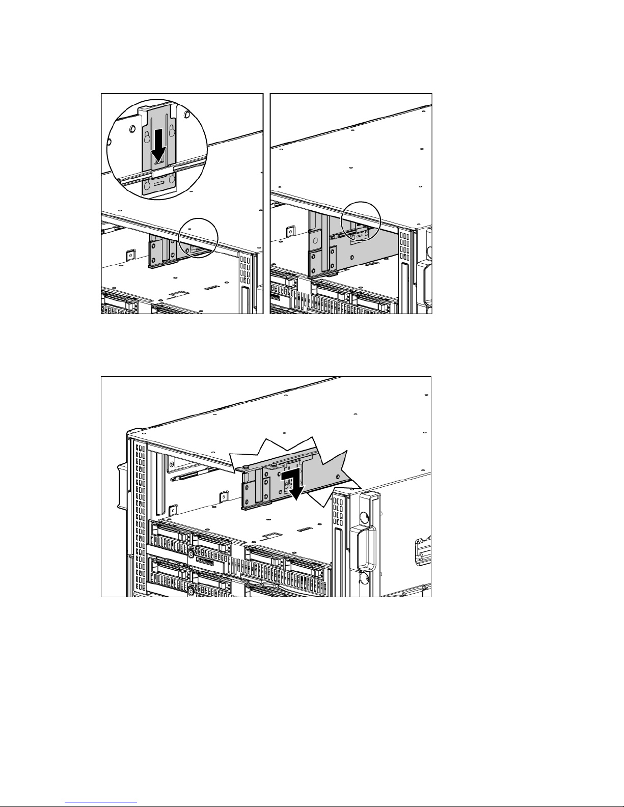
Removing a c7000 device bay divider
1. Slide the device bay shelf locking tab to the left to open it.
Setup 22
2.
Push the device bay shelf back until it stops, lift the right side slightly to disengage the two tabs from the
divider wall, and then rotate the right edge downward (clockwise).
3. Lift the left side of the device bay shelf to disengage the three tabs from the divider wall, and then
remove it from the enclosure.
Setup 23
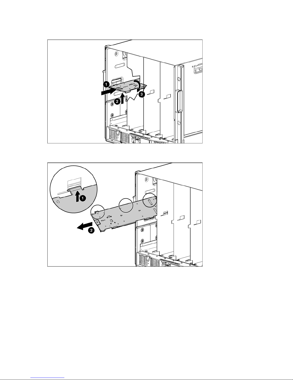
Removing a c3000 device bay mini-divider or device bay divider
1. Slide the locking tab down.
2. Remove the mini-divider or divider:
o c3000 mini-divider:
Push the divider toward the back of the enclosure until the divider drops out of the chassis.
o c3000 divider:
a. Push the divider toward the back of the enclosure until it stops.
b. Slide the divider to the left to disengage the tabs from the wall.
c. Rotate the divider clockwise.
Setup 24
d.
Remove the divider from the enclosure.
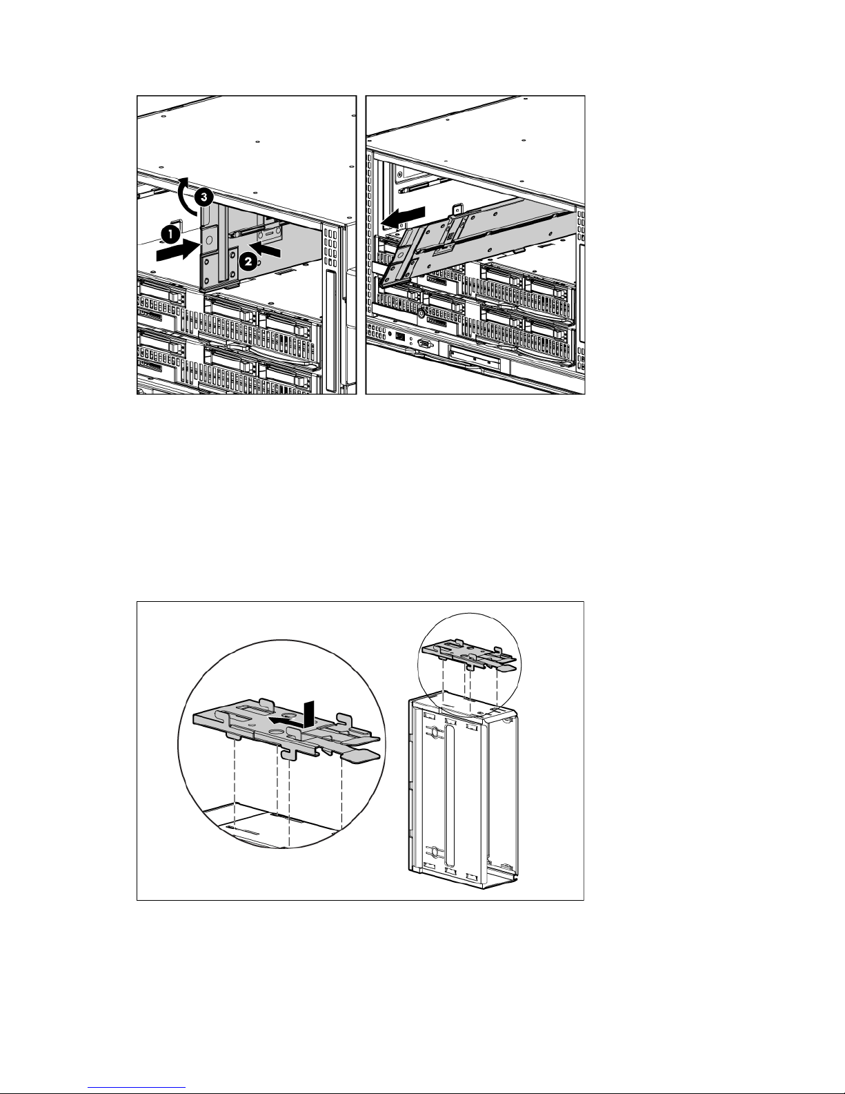
Creating a full-height device bay blank
1. Obtain the coupler plate:
o If you are using a device bay blank that came with the enclosure, the coupler plate can be found
with the contents of the full-height device shipping box.
o If you are using a device bay blank that you purchased as an option, remove the coupler plate from
inside the blank.
2. Fit the coupler plate into the slots on top of the blank, and then slide the coupler plate back until it snaps
into place.
Setup 25
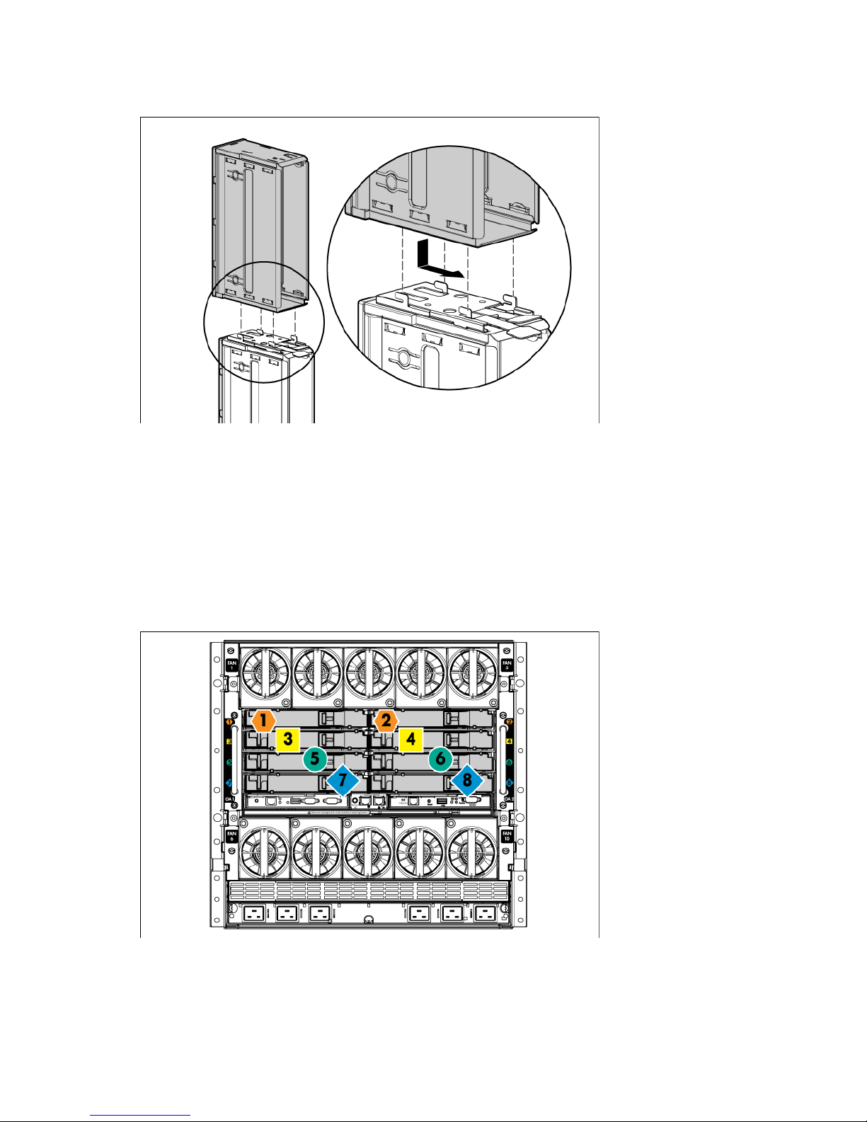
3.
Fit the slots on the bottom of the second blank on to the tabs on the coupler plate, and then slide the
second blank forward until it snaps in place.
4. Install the full-height blank into the device bay.
Installing interconnect modules
For specific steps to install interconnect modules, see the documentation that ships with the interconnect
Interconnect bay numbering and device mapping
module.
• HP BladeSystem c7000 Enclosure
Setup 26
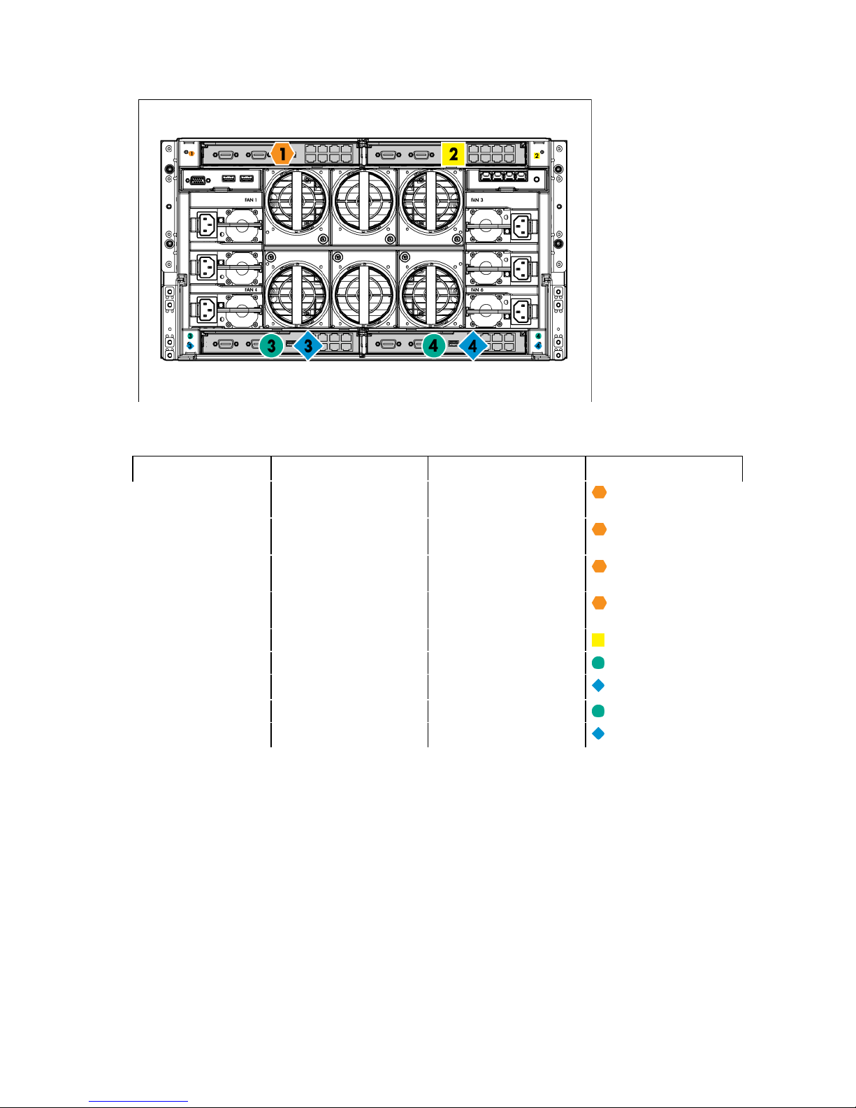
• HP BladeSystem c3000 Enclosure
(Embedded)
To support network connections for specific signals, install an interconnect module in the bay corresponding
to the embedded adapter or mezzanine signals.
Server blade signal c7000 interconnect bay c3000 interconnect bay Interconnect bay labels
FlexFabric adapter 1
(Embedded)
FlexFabric adapter 2
(Embedded)
FlexFabric adapter 3
1 1
2 1
1 1
FlexFabric adapter 4
(Embedded)
Mezzanine 1
Mezzanine 2
Mezzanine 3
* Dual port mezzanine card ports and four-port mezzanine card ports 1 and 2
** Four-port mezzanine card ports 3 and 4
2 1
3 and 4 2
5 and 6* 3 and 4
7 and 8** 3 and 4
5 and 6** 3 and 4
7 and 8* 3 and 4
For detailed port mapping information, see the HP BladeSystem enclosure installation poster or the
HP BladeSystem enclosure setup and installation guide on the HP website
(http://www.hp.com/go/bladesystem/documentation).
Connecting to the network
To connect the HP BladeSystem to a network, each enclosure must be configured with network interconnect
devices to manage signals between the server blades and the external network.
Setup 27
Two types of interconnect modules are available for HP BladeSystem c-Class enclosures: Pass-Thru modules
and switch modules. For more information about interconnect module options, see the HP website
(http://www.hp.com/go/bladesystem/interconnects).
IMPORTANT: To connect to a network with a Pass-Thru module, always connect the Pass-Thru
module to a network device that supports Gigabit speed.
Installing server blade options
Before installing and initializing the server blade, install any server blade options, such as an additional
processor, hard drive, or mezzanine card.
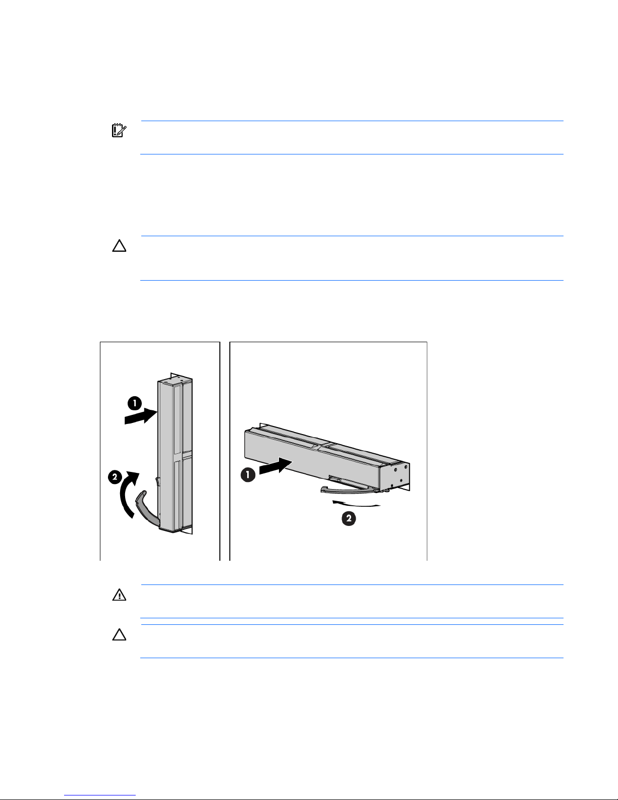
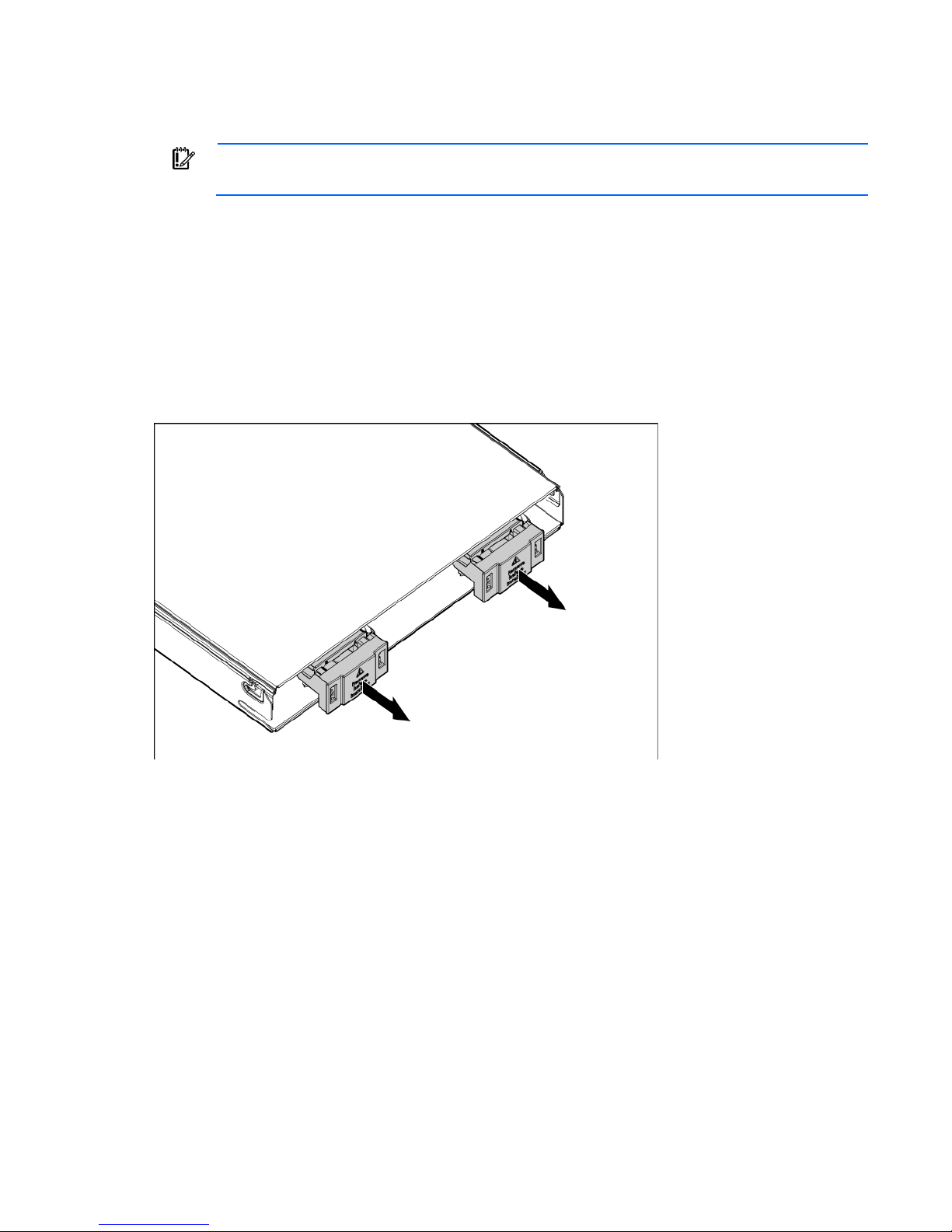
Installing a server blade
1. Remove the connector covers.
Setup 28
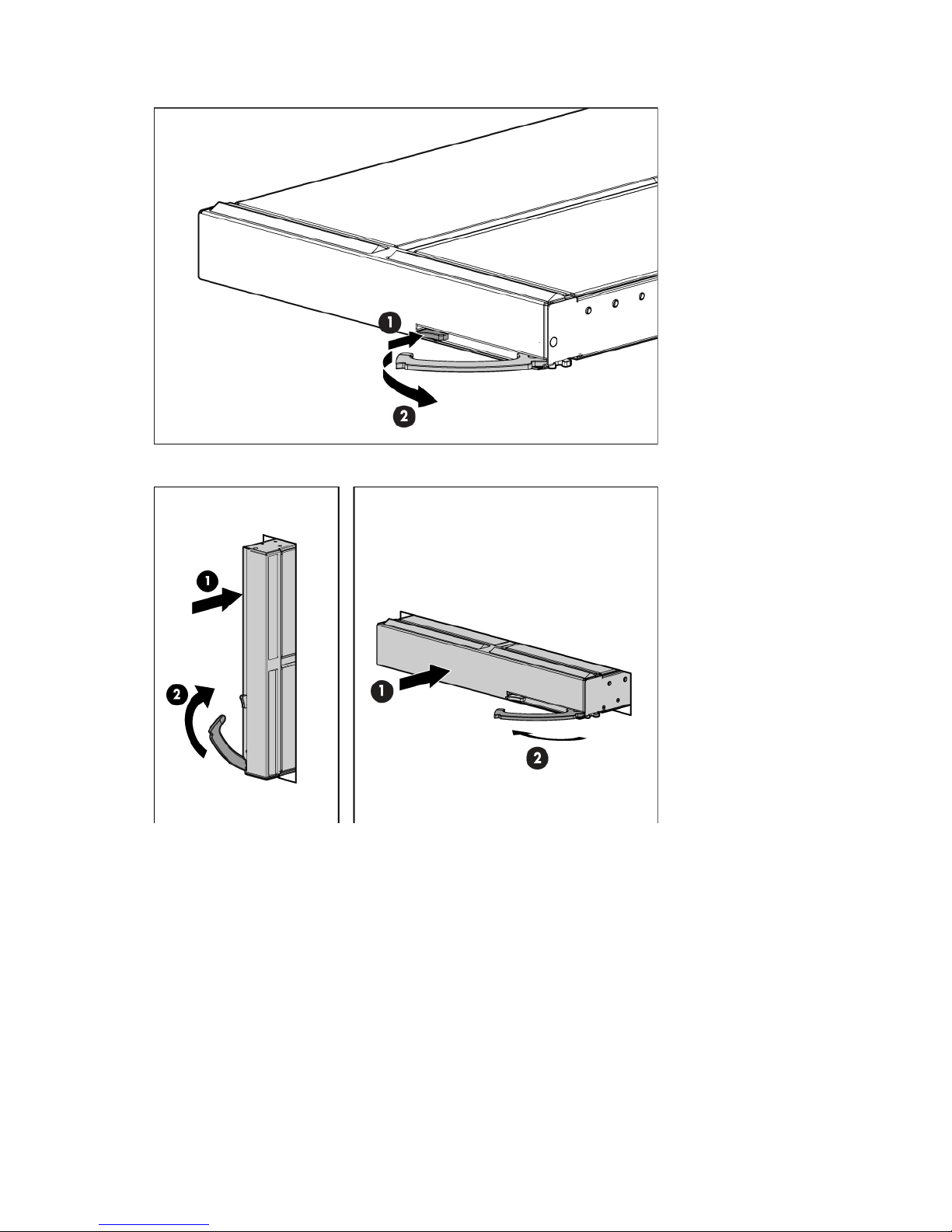
2.
Prepare the server blade for installation.
3. Install the server blade.
Completing the configuration
To complete the server blade and HP BladeSystem configuration, see the overview card that ships with the
enclosure.
Setup 29

Hardware options installation
Introduction
If more than one option is being installed, read the installation instructions for all the hardware options and
identify similar steps to streamline the installation process.
WARNING: To reduce the risk of personal injury from hot surfaces, allow the drives and the
Processor option
internal system components to cool before touching them.
CAUTION: To prevent damage to electrical components, properly ground the server before
beginning any installation procedure. Improper grounding can cause electrostatic discharge.
The base configuration for an HP ProLiant BL620c G7 Server Blade is one processor. When installing an
optional processor, install the second processor in processor socket 2.
The server blade ships with one of two different system boards that each support specific processors:
• Intel® Xeon® E7 family processors (E7-2800 family and the E7-8867L low-voltage processor)
• Intel Xeon 6500/7500 series processors
A server blade that originally ships with Intel Xeon E7 family processors supports only Intel Xeon processor
E7 family processors. A server blade that originally ships with Intel Xeon 6500 or 7500 series processors
supports only Intel Xeon 6500 or 7500 series processors. All installed processors must be identical.
You can use one of four methods to determine what processor shipped with the server blade:
• Use HP Insight Control and the Systems Insight Manager management console configured with WBEM.
For more information, see the documentation on the HP website
(http://www.hp.com/go/foundationmgmt/docs).
• Use the operating system, for example, the System Properties for Windows®.
• View the server POST start-up screen data.
• Press F10 at boot to run the Inspect Utility, and then view the system management BIOS page.
HP recommends that all installed processors have at least two identical DIMMs installed in the associated
DIMM sockets. For more information, see "DIMM installation guidelines (on page 38)."
WARNING: To reduce the risk of personal injury from hot surfaces, allow the drives and the
internal system components to cool before touching them.
CAUTION: To prevent possible server blade malfunction and damage to the equipment,
multiprocessor configurations must contain processors with the same part number.
Hardware options installation 30
 Loading...