

HP ProLiant BL620c, ProLiant 100 Troubleshooting Manual

HP ProLiant Servers
Troubleshooting Guide
Part Number 375445-009
June 2010 (Ninth Edition)

© Copyright 2004, 2010 Hewlett-Packard Development Company, L.P.
The information contained herein is subject to change without notice. The only warranties for HP products and services are set forth in the express
warranty statements accompanying such products and services. Nothing herein should be construed as constituting an additional warranty. HP
shall not be liable for technical or editorial errors or omissions contained herein.
Microsoft, Windows, and Windows Server are U.S. registered trademarks of Microsoft Corporation.
Intel, Pentium, and Itanium are trademarks or registered trademarks of Intel Corporation or its subsidiaries in the United States and other
countries.
Intended audience
This document is for the person who installs, administers, and troubleshoots servers and storage systems.
HP assumes you are qualified in the servicing of computer equipment and trained in recognizing hazards
in products with hazardous energy levels.

Contents
Introduction .................................................................................................................................. 8
What's new ................................................................................................................................................. 8
Revision history ............................................................................................................................................ 8
375445-xx8 (July 2009) ..................................................................................................................... 8
375445-xx7 (November 2008) ........................................................................................................... 9
375445-xx6 (September 2007)......................................................................................................... 10
375445-xx5 (June 2006) .................................................................................................................. 10
375445-xx4 (May 2006) ................................................................................................................. 10
375445-xx3 (September 2005)......................................................................................................... 11
Getting started ............................................................................................................................ 12
HP ProLiant 100 Series Server troubleshooting information ............................................................................. 12
How to use this guide ................................................................................................................................. 12
Pre-diagnostic steps .................................................................................................................................... 13
Important safety information .............................................................................................................. 13
Symptom information ........................................................................................................................ 16
Prepare the server for diagnosis ......................................................................................................... 16
Common problem resolution ........................................................................................................ 18
Loose connections ...................................................................................................................................... 18
Service notifications .................................................................................................................................... 18
Firmware updates ...................................................................................................................................... 18
DIMM handling guidelines .......................................................................................................................... 19
Hard drive guidelines ................................................................................................................................. 19
SAS and SATA hard drive guidelines ................................................................................................. 19
SCSI hard drive guidelines ................................................................................................................ 19
Hard drive LED combinations ...................................................................................................................... 20
Hot-plug SCSI hard drive LED combinations ........................................................................................ 20
SAS and SATA hard drive LED combinations ...................................................................................... 20
Server updates with an HP Trusted Platform Module and BitLocker™ enabled ................................................... 21
Diagnostic flowcharts .................................................................................................................. 23
Troubleshooting flowcharts .......................................................................................................................... 23
Troubleshooting flowchart reference websites ...................................................................................... 23
Start diagnosis flowchart ................................................................................................................... 25
General diagnosis flowchart .............................................................................................................. 25
Power-on problems flowchart ............................................................................................................. 27
POST problems flowchart .................................................................................................................. 30
Operating system boot problems flowchart ......................................................................................... 32
Server fault indications flowchart ....................................................................................................... 33
Hardware problems .................................................................................................................... 37
Procedures for all ProLiant servers ................................................................................................................ 37
Power problems ......................................................................................................................................... 37
Power source problems ..................................................................................................................... 37
Power supply problems ..................................................................................................................... 37
UPS problems
General hardware problems ....................................................................................................................... 39
.................................................................................................................................. 38

Problems with new hardware ............................................................................................................ 39
Unknown problem ............................................................................................................................ 40
Third-party device problems .............................................................................................................. 40
Internal system problems ............................................................................................................................. 41
Battery pack problems ...................................................................................................................... 41
CD-ROM and DVD drive problems ..................................................................................................... 41
Diskette drive problems ..................................................................................................................... 42
Drive problems (hard drives and solid state drives) .............................................................................. 43
SD card problems ............................................................................................................................ 46
USB drive key problems .................................................................................................................... 46
Fan problems ................................................................................................................................... 46
HP Trusted Platform Module problems ................................................................................................ 47
Memory problems ............................................................................................................................ 48
PPM problems .................................................................................................................................. 50
Processor problems .......................................................................................................................... 50
Tape drive problems ......................................................................................................................... 51
Graphics and video adapter problems ............................................................................................... 52
System open circuits and short circuits .......................................................................................................... 53
External device problems ............................................................................................................................ 53
Video problems................................................................................................................................ 53
Mouse and keyboard problems ......................................................................................................... 54
Audio problems ............................................................................................................................... 55
Printer problems ............................................................................................................................... 55
Cable problems ............................................................................................................................... 55
Local I/O cable problems ................................................................................................................. 55
Modem problems ............................................................................................................................. 56
Network controller problems ............................................................................................................. 58
Expansion board problems................................................................................................................ 59
Software problems ...................................................................................................................... 60
Operating system problems and resolutions .................................................................................................. 60
Operating system problems ............................................................................................................... 60
Operating system updates ................................................................................................................. 61
Restoring to a backed-up version ....................................................................................................... 62
When to Reconfigure or Reload Software ........................................................................................... 62
Linux operating systems .................................................................................................................... 63
Application software problems .................................................................................................................... 63
Software locks up ............................................................................................................................. 63
Errors occur after a software setting is changed ................................................................................... 63
Errors occur after the system software is changed ................................................................................ 63
Errors occur after an application is installed ........................................................................................ 63
ROM problems .......................................................................................................................................... 64
Remote ROM flash problems ............................................................................................................. 64
Boot problems .................................................................................................................................. 65
Software tools and solutions ......................................................................................................... 67
Configuration tools ..................................................................................................................................... 67
SmartStart software .......................................................................................................................... 67
HP ROM-Based Setup Utility .............................................................................................................. 67
Array Configuration Utility ................................................................................................................ 70
Option ROM Configuration for Arrays................................................................................................ 71
Re-entering the serial number and product ID ...................................................................................... 71
Management tools...................................................................................................................................... 72
Automatic Server Recovery ................................................................................................................ 72

ROMPaq utility ................................................................................................................................. 72
Remote Insight Lights-Out Edition II ..................................................................................................... 73
iLO and iLO 2 technology ................................................................................................................. 73
Integrated Lights-Out 3 technology ..................................................................................................... 73
Erase Utility ..................................................................................................................................... 74
Redundant ROM support ................................................................................................................... 74
USB support .................................................................................................................................... 74
Diagnostic tools ......................................................................................................................................... 75
HP Insight Diagnostics ...................................................................................................................... 75
HP Insight Diagnostics survey functionality .......................................................................................... 75
Integrated Management Log .............................................................................................................. 76
Array diagnostic software ................................................................................................................. 76
Remote support and analysis tools ............................................................................................................... 77
HP Insight Remote Support software ................................................................................................... 77
Keeping the system current .......................................................................................................................... 77
Drivers ............................................................................................................................................ 77
Version control ................................................................................................................................. 78
ProLiant Support Packs ...................................................................................................................... 78
Operating system version support ...................................................................................................... 78
Firmware ......................................................................................................................................... 78
HP Smart Update Manager ............................................................................................................... 79
System Online ROM flash component utility ........................................................................................ 79
Subscriber's choice .......................................................................................................................... 80
Care Pack ....................................................................................................................................... 80
Firmware maintenance ............................................................................................................................... 80
Types of ROM.................................................................................................................................. 80
Verifying firmware versions ............................................................................................................... 82
Updating firmware ........................................................................................................................... 82
Unsupported processor stepping with Intel® processors ....................................................................... 85
Unsupported processor stepping with AMD processors ........................................................................ 85
HP resources for troubleshooting ................................................................................................... 86
Online resources ........................................................................................................................................ 86
HP Technical Support website ............................................................................................................ 86
HP Guided Troubleshooting website ................................................................................................... 86
Server documentation ....................................................................................................................... 86
White papers .................................................................................................................................. 86
Service notifications, advisories, and notices ....................................................................................... 86
Subscription services ........................................................................................................................ 86
HP Care Pack Services...................................................................................................................... 87
Product information resources ...................................................................................................................... 87
Additional product information .......................................................................................................... 87
Registering the server........................................................................................................................ 87
Overview of server features and installation instructions ....................................................................... 87
Key features, option part numbers ...................................................................................................... 87
Server and option specifications, symbols, installation warnings, and notices ......................................... 87
Teardown procedures, part numbers, specifications ............................................................................. 88
Technical topics ............................................................................................................................... 88
Product installation resources ....................................................................................................................... 88
Switch settings, LED functions, drive, memory, expansion board and processor installation instructions, and
board layouts .................................................................................................................................. 88
External cabling information .............................................................................................................. 88
Power capacity ................................................................................................................................ 88
Product configuration resources ................................................................................................................... 88

Device driver information .................................................................................................................. 88
DDR3 memory configuration.............................................................................................................. 89
Operating System Version Support ..................................................................................................... 89
Operating system installation and configuration information (for factory-installed operating systems) ......... 89
Server configuration information ........................................................................................................ 89
Installation and configuration information for the server setup software .................................................. 89
Software installation and configuration of the server ............................................................................ 89
iLO information ................................................................................................................................ 89
Management of the server ................................................................................................................. 89
Installation and configuration information for the server management system .......................................... 90
Fault tolerance, security, care and maintenance, configuration and setup .............................................. 90
Error messages ........................................................................................................................... 91
ADU error messages ................................................................................................................................... 91
Introduction to ADU error messages ................................................................................................... 91
ADU version 8.0 through 8.28 error messages ................................................................................. 111
POST error messages and beep codes ....................................................................................................... 115
Introduction to POST error messages ................................................................................................ 115
Non-numeric messages or beeps only............................................................................................... 116
100 Series .................................................................................................................................... 125
200 Series .................................................................................................................................... 128
300 Series .................................................................................................................................... 132
400 Series .................................................................................................................................... 133
600 Series .................................................................................................................................... 133
1100 Series .................................................................................................................................. 134
1600 Series .................................................................................................................................. 134
1700 Series .................................................................................................................................. 138
Event list error messages ........................................................................................................................... 157
Introduction to event list error messages ............................................................................................ 157
A CPU Power Module (System Board, Socket X)... ............................................................................. 158
ASR Lockup Detected: Cause ........................................................................................................... 158
Automatic operating system shutdown initiated due to fan failure ........................................................ 158
Automatic Operating System Shutdown Initiated Due to Overheat Condition... ..................................... 158
Blue Screen Trap: Cause [NT]... ...................................................................................................... 159
Corrected Memory Error Threshold Passed (Slot X, Memory Module Y)... ............................................. 159
EISA Expansion Bus Master Timeout (Slot X)... ................................................................................... 159
PCI Bus Error (Slot X, Bus Y, Device Z, Function X) ............................................................................. 159
Processor Correctable Error Threshold Passed (Slot X, Socket Y) .......................................................... 159
Processor Uncorrectable Internal Error (Slot X, Socket Y) ..................................................................... 159
Real-Time Clock Battery Failing ........................................................................................................ 159
System AC Power Overload (Power Supply X) ................................................................................... 160
System AC Power Problem (Power Supply X) ..................................................................................... 160
System Fan Failure (Fan X, Location) ................................................................................................ 160
System Fans Not Redundant ............................................................................................................ 160
System Overheating (Zone X, Location) ............................................................................................ 160
System Power Supplies Not Redundant ............................................................................................. 160
System Power Supply Failure (Power Supply X) .................................................................................. 160
Unrecoverable Host Bus Data Parity Error... ...................................................................................... 160
Uncorrectable Memory Error (Slot X, Memory Module Y).................................................................... 161
HP BladeSystem p-Class infrastructure error codes ....................................................................................... 161
Server blade management module error codes .................................................................................. 161
Power management module error codes ........................................................................................... 164
Port 85 codes and iLO messages ............................................................................................................... 165
Troubleshooting the system using port 85 codes ................................................................................ 165

Processor-related port 85 codes ....................................................................................................... 166
Memory-related port 85 codes......................................................................................................... 167
Expansion board-related port 85 codes ............................................................................................ 167
Miscellaneous port 85 codes ........................................................................................................... 168
Windows® Event Log processor error codes ............................................................................................... 169
Message ID: 4137 ......................................................................................................................... 169
Message ID: 4140 ......................................................................................................................... 169
Message ID: 4141 ......................................................................................................................... 169
Message ID: 4169 ......................................................................................................................... 169
Message ID: 4190 ......................................................................................................................... 169
Insight Diagnostics processor error codes ................................................................................................... 169
MSG_CPU_RR_1 ............................................................................................................................ 169
MSG_CPU_RR_2 ............................................................................................................................ 170
MSG_CPU_RR_3 ............................................................................................................................ 170
MSG_CPU_RR_5 ............................................................................................................................ 170
MSG_CPU_RR_6 ............................................................................................................................ 170
MSG_CPU_RR_7 ............................................................................................................................ 170
MSG_CPU_RR_8 ............................................................................................................................ 171
MSG_CPU_RR_9 ............................................................................................................................ 171
MSG_CPU_RR_10 .......................................................................................................................... 171
MSG_CPU_RR_11 .......................................................................................................................... 171
MSG_CPU_RR_12 .......................................................................................................................... 171
MSG_CPU_RR_13 .......................................................................................................................... 171
MSG_CPU_RR_14 .......................................................................................................................... 171
MSG_CPU_RR_15 .......................................................................................................................... 171
MSG_CPU_RR_16 .......................................................................................................................... 171
MSG_CPU_RR_17 .......................................................................................................................... 172
Contacting HP .......................................................................................................................... 173
Contacting HP technical support or an authorized reseller ............................................................................ 173
Customer self repair ................................................................................................................................. 173
Server information you need ...................................................................................................................... 173
Operating system information you need ..................................................................................................... 174
Microsoft® operating systems .......................................................................................................... 174
Linux operating systems .................................................................................................................. 175
Novell NetWare operating systems .................................................................................................. 176
SCO operating systems................................................................................................................... 176
IBM OS/2 operating systems .......................................................................................................... 177
Sun Solaris operating systems .......................................................................................................... 178
Acronyms and abbreviations ...................................................................................................... 179
Index ....................................................................................................................................... 184

Introduction
What's new
The ninth edition of the HP ProLiant Servers Troubleshooting Guide, part number 375445-xx9, includes
the following additions and updates:
• Added new section to Getting started (on page 12):
Breaking the server down to the minimum hardware configuration (on page 17)
• Updated Diagnostic flowcharts (on page 23):
o General diagnosis flowchart (on page 25)
o Server power-on problems flowchart (on page 27)
o Server and p-Class server blade POST problems flowchart (on page 31)
o c-Class server blade POST problems flowchart (on page 32)
o Server and p-Class server blade fault indications flowchart (on page 34)
• Added and updated sections in Software tools and solutions (on page 67):
o Integrated Lights-Out 3 technology (on page 73)
o Firmware (on page 78)
o HP Smart Update Manager (on page 79)
• Added new sections to Hardware problems (on page 37):
o Battery pack problems (on page 41)
o Cable problems (on page 55)
• Added a new section to Software problems (on page 60):
ROM problems (on page 64)
• Updated a section in Online resources (on page 86):
Server documentation (on page 86)
• Updated Firmware maintenance (on page 80).
• Added new error messages:
o ADU error messages (on page 91)
o POST error messages and beep codes (on page 115)
Revision history
375445-xx8 (July 2009)
The eighth edition of the HP ProLiant Servers Troubleshooting Guide, part number 375445-xx8, included
the following additions and updates:
Introduction 8

• Added information to the introduction for the server power-on problems flowchart (on page 27).
• Added new steps to Power problems (on page 37).
• Added a new section to Fan problems (on page 46):
All fans in an HP ProLiant G6 server are not spinning or are not spinning at the same speed (on
page 47)
• Added a new section to Memory problems (on page 48):
Server fails to boot, all DIMM LEDs illuminate amber, .... (on page 49)
• Updated the content for Tape drive problems (on page 51).
• Added new sections to Software tools and solutions (on page 67) :
o Diagnostics tasks (on page 70)
o HP Insight Server Migration software for ProLiant
o Array diagnostic software (on page 76)
o HP Insight Remote Support software (on page 77)
• Added new content to HP Resources for Troubleshooting (on page 86):
o HP Guided Troubleshooting website (on page 86)
o DDR3 memory configuration (on page 89)
o Power capacity (on page 88)
• Added new error messages:
o ADU Error Messages (on page 91)
o POST error messages and beep codes (on page 115)
375445-xx7 (November 2008)
The seventh edition of the HP ProLiant Servers Troubleshooting Guide, part number 375445-xx7, included
the following additions and updates:
• Added new information about Server updates with an HP Trusted Platform Module and BitLocker™
enabled (on page 21) to Common problem resolution (on page 18)
• Added TPM information to Drive problems (hard drives and solid state drives) (on page 43)
• Added information about HP BladeSystem c-Class enclosure fan problems to Fan problems (on page
46)
• Added HP Trusted Platform Module problems (on page 47) to Hardware problems (on page 37)
• Added SD card problems (on page 46) to Hardware problems (on page 37)
• Added USB drive key problems (on page 46) to Hardware problems (on page 37)
• Added TPM information to Remote ROM flash problems (on page 64)
• Added Service Essentials Remote Support Pack to Software tools and solutions (on page 67)
• Added TPM information to Firmware maintenance (on page 80)
• Updated the ADU error messages (on page 91) section to reflect the supported versions for the
messages in this document
• Updated and added new POST error messages and beep codes (on page 115)
Introduction 9

375445-xx6 (September 2007)
The sixth edition of the HP ProLiant Servers Troubleshooting Guide, part number 375445-xx6, included
the following additions and updates:
• Added new information about preventing electrostatic discharge (on page 15).
• Added new DIMM handling guidelines (on page 19).
• Added new procedures for troubleshooting drive problems (hard drives and solid state drives) (on
page 43).
• Added information on new software tools and solutions:
o HP Insight Control Environment Suites
o HP Smart Update Manager (on page 79)
• Improved firmware maintenance (on page 80):
o Added new technology
o Expanded existing information
o Added new firmware update procedures for unsupported processor stepping
375445-xx5 (June 2006)
The fifth edition of the HP ProLiant Servers Troubleshooting Guide, part number 375445-xx5, included the
following additions:
• Added three new c-Class server blade flowcharts:
o c-Class server blade power-on problems flowchart (on page 29)
o c-Class server blade POST problems flowchart (on page 32)
o c-Class server blade fault indications flowchart (on page 36)
• Added new processor error codes:
o Windows® Event Log processor error codes (on page 169)
o Insight Diagnostics processor error codes (on page 169)
375445-xx4 (May 2006)
The fourth edition of the HP ProLiant Servers Troubleshooting Guide, part number 375445-xx4, included
the following additions:
• Hot-plug SAS and SATA hard drive LED combinations (on page 20)
• Operating system issues with Intel® dual-core processors (Hyper-Threading enabled) (on page 61)
• Tape drive problems (on page 51)
• New error messages in ADU error messages (on page 91) and POST error messages and beep
codes (on page 115)
Introduction 10

375445-xx3 (September 2005)
The third edition of the HP ProLiant Servers Troubleshooting Guide, part number 375445-xx3, included
the following changes:
• Updated SCSI hard drive guidelines
• Added hot-plug SCSI hard drive LED combinations (on page 20)
• Updated diagnostic flowcharts (on page 23)
• Added operating system problems (on page 60)
• Added Port 85 codes and iLO messages (on page 165)
• Added new error messages to ADU error messages and POST error messages and beep codes
• Updated contacting HP:
o Contacting HP technical support or an authorized reseller
o Server information you need
Introduction 11

Getting started
HP ProLiant 100 Series Server troubleshooting
information
For HP ProLiant 100 Series Server troubleshooting information, see the respective server user guides.
How to use this guide
NOTE: For common troubleshooting procedures, the term "server" is used to mean servers
This guide provides common procedures and solutions for the many levels of troubleshooting a ProLiant
server—from the most basic connector issues to complex software configuration problems.
To understand the sections of this guide and to identify the best starting point for a problem, use the
following descriptions:
• Common problem resolution (on page 18)
• Diagnostic flowcharts (on page 23)
• Hardware problems (on page 37)
and server blades.
Many server problems are caused by loose connections, outdated firmware, and other issues. Use
this section to perform basic troubleshooting for common problems.
When a server exhibits symptoms that do not immediately pinpoint the problem, use this section to
begin troubleshooting. The section contains a series of flowcharts that provide a common
troubleshooting process for ProLiant servers. The flowcharts identify a diagnostic tool or a process to
help solve the problem.
When the symptoms point to a specific component, use this section to find solutions for problems
with power, general components, system boards, system open circuits and short circuits, and
external devices.
• Software problems (on page 60)
When you have a known, specific software problem, use this section to identify a solution to the
problem.
• Software tools and solutions (on page 67)
Use this section as a reference for software tools and utilities.
• HP resources for troubleshooting (on page 86)
When additional information becomes necessary, use this section to identify websites and
supplemental documents that contain troubleshooting information.
• Error messages (on page 91)
Use this section for a complete list of the following messages:
Getting started 12
o
ADU error messages (on page 91)
o POST error messages and beep codes (on page 115)
o Event list error messages (on page 157)
o HP BladeSystem infrastructure error codes ("HP BladeSystem p-Class infrastructure error codes"
on page 161)
o Port 85 codes and iLO messages (on page 165)
Pre-diagnostic steps
WARNING: To avoid potential problems, ALWAYS read the warnings and cautionary
information in the server documentation before removing, replacing, reseating, or modifying
1. Review the important safety information (on page 13).
2. Gather symptom information (on page 16).
3. Prepare the server for diagnosis (on page 16).
4. Use the Start diagnosis flowchart (on page 25) to begin the diagnostic process.
Important safety information
Familiarize yourself with the safety information in the following sections before troubleshooting the server.
system components.
IMPORTANT: This guide provides information for multiple servers. Some information may not
apply to the server you are troubleshooting. Refer to the server documentation for information
on procedures, hardware options, software tools, and operating systems supported by the
server.
Important safety information
Before servicing this product, read the Important Safety Information document provided with the server.
Symbols on equipment
The following symbols may be placed on equipment to indicate the presence of potentially hazardous
conditions.
This symbol indicates the presence of hazardous energy circuits or electric shock
hazards. Refer all servicing to qualified personnel.
WARNING: To reduce the risk of injury from electric shock hazards, do not open this
enclosure. Refer all maintenance, upgrades, and servicing to qualified personnel.
This symbol indicates the presence of electric shock hazards. The area contains no
user or field serviceable parts. Do not open for any reason.
WARNING: To reduce the risk of injury from electric shock hazards, do not open this
enclosure.
Getting started 13
This symbol on an RJ-45 receptacle indicates a network interface connection.
WARNING: To reduce the risk of electric shock, fire, or damage to the equipment,
do not plug telephone or telecommunications connectors into this receptacle.
This symbol indicates the presence of a hot surface or hot component. If this surface
is contacted, the potential for injury exists.
WARNING: To reduce the risk of injury from a hot component, allow the surface to
cool before touching.
This symbol indicates that the component exceeds the recommended weight for one
weight in kg
weight in lb
individual to handle safely.
WARNING: To reduce the risk of personal injury or damage to the equipment,
observe local occupational health and safety requirements and guidelines for
manual material handling.
These symbols, on power supplies or systems, indicate that the equipment is
supplied by multiple sources of power.
WARNING: To reduce the risk of injury from electric shock, remove all power
cords to completely disconnect power from the system.
Warnings and cautions
WARNING: Only authorized technicians trained by HP should attempt to repair this
equipment. All troubleshooting and repair procedures are detailed to allow only
subassembly/module-level repair. Because of the complexity of the individual boards and
subassemblies, no one should attempt to make repairs at the component level or to make
modifications to any printed wiring board. Improper repairs can create a safety hazard.
WARNING: To reduce the risk of personal injury or damage to the equipment, be sure that:
• The leveling feet are extended to the floor.
• The full weight of the rack rests on the leveling feet.
• The stabilizing feet are attached to the rack if it is a single-rack installation.
• The racks are coupled together in multiple-rack installations.
• Only one component is extended at a time. A rack may become unstable if more than one
component is extended for any reason.
WARNING: To reduce the risk of electric shock or damage to the equipment:
• Do not disable the power cord grounding plug. The grounding plug is an important safety
feature.
• Plug the power cord into a grounded (earthed) electrical outlet that is easily accessible at
all times.
• Unplug the power cord from the power supply to disconnect power to the equipment.
• Do not route the power cord where it can be walked on or pinched by items placed
against it. Pay particular attention to the plug, electrical outlet, and the point where the
cord extends from the server.
Getting started 14
WARNING: To reduce the risk of personal injury or damage to the equipment:
• Observe local occupation health and safety requirements and guidelines for
weight in kg
weight in lb
• Obtain adequate assistance to lift and stabilize the chassis during installation or
• The server is unstable when not fastened to the rails.
• When mounting the server in a rack, remove the power supplies and any other
CAUTION: To properly ventilate the system, you must provide at least 7.6 cm (3.0 in) of
clearance at the front and back of the server.
CAUTION: The server is designed to be electrically grounded (earthed). To ensure proper
operation, plug the AC power cord into a properly grounded AC outlet only.
Electrostatic discharge
Preventing electrostatic discharge
manual handling.
removal.
removable module to reduce the overall weight of the product.
To prevent damaging the system, be aware of the precautions you need to follow when setting up the
system or handling parts. A discharge of static electricity from a finger or other conductor may damage
system boards or other static-sensitive devices. This type of damage may reduce the life expectancy of the
device.
To prevent electrostatic damage:
• Avoid hand contact by transporting and storing products in static-safe containers.
• Keep electrostatic-sensitive parts in their containers until they arrive at static-free workstations.
• Place parts on a grounded surface before removing them from their containers.
• Avoid touching pins, leads, or circuitry.
• Always be properly grounded when touching a static-sensitive component or assembly.
Grounding methods to prevent electrostatic discharge
Several methods are used for grounding. Use one or more of the following methods when handling or
installing electrostatic-sensitive parts:
• Use a wrist strap connected by a ground cord to a grounded workstation or computer chassis. Wrist
straps are flexible straps with a minimum of 1 megohm ±10 percent resistance in the ground cords.
To provide proper ground, wear the strap snug against the skin.
• Use heel straps, toe straps, or boot straps at standing workstations. Wear the straps on both feet
when standing on conductive floors or dissipating floor mats.
• Use conductive field service tools.
• Use a portable field service kit with a folding static-dissipating work mat.
If you do not have any of the suggested equipment for proper grounding, have an authorized reseller
install the part.
Getting started 15

For more information on static electricity or assistance with product installation, contact an authorized
reseller.
Symptom information
Before troubleshooting a server problem, collect the following information:
• What events preceded the failure? After which steps does the problem occur?
• What has been changed since the time the server was working?
• Did you recently add or remove hardware or software? If so, did you remember to change the
appropriate settings in the server setup utility, if necessary?
• How long has the server exhibited problem symptoms?
• If the problem occurs randomly, what is the duration or frequency?
To answer these questions, the following information may be useful:
• Run HP Insight Diagnostics (on page 75) and use the survey page to view the current configuration
or to compare it to previous configurations.
• Refer to your hardware and software records for information.
• Refer to server LEDs and their statuses.
Prepare the server for diagnosis
1. Be sure the server is in the proper operating environment with adequate power, air conditioning,
and humidity control. For required environmental conditions, see the server documentation (on page
86).
2. Record any error messages displayed by the system.
3. Remove all diskettes, CD-ROMs, DVD-ROMs, and USB drive keys.
4. Power down the server and peripheral devices if you will be diagnosing the server offline. If
possible, always perform an orderly shutdown:
a. Exit any applications.
b. Exit the operating system.
c. Power down the server.
5. Disconnect any peripheral devices not required for testing (any devices not necessary to power up
the server). Do not disconnect the printer if you want to use it to print error messages.
6. Collect all tools and utilities, such as a Torx screwdriver, loopback adapters, ESD wrist strap, and
software utilities, necessary to troubleshoot the problem.
o You must have the appropriate Health Drivers and Management Agents installed on the server.
To verify the server configuration, connect to the System Management homepage and select
Version Control Agent. The VCA gives you a list of names and versions of all installed HP drivers,
Management Agents, and utilities, and whether they are up-to-date.
o HP recommends you have access to the server documentation (on page 86) for server-specific
information.
o HP recommends you have access to the SmartStart CD for value-added software and drivers
required during the troubleshooting process. Download the current version of SmartStart from the
HP website (http://www.hp.com/servers/smartstart
).
Getting started 16

Breaking the server down to the minimum hardware configuration
During the troubleshooting process, you may be asked to break the server down to the minimum
hardware configuration. A minimum configuration consists of only the components needed to boot the
server and successfully pass POST.
When requested to break the server down to the minimum configuration, uninstall the following
components, if installed:
• All additional processors (leave one installed)
• All additional DIMMs
Leave only the minimum required to boot the server—either one DIMM or a pair of DIMMs. For more
information, see the memory guidelines in the server user guide.
• All additional cooling fans, if applicable
For minimum fan configuration, see the server user guide.
• All additional power supplies, if applicable (leave one installed)
• All hard drives
• All optical drives (DVD-ROM, CD-ROM, and so forth)
• All optional mezzanine cards
• All expansion boards
Before removing the components, be sure to determine the minimum configuration for each component
and follow all guidelines in the server user guide.
Getting started 17

Common problem resolution
Loose connections
Action:
• Be sure all power cords are securely connected.
• Be sure all cables are properly aligned and securely connected for all external and internal
components.
• Remove and check all data and power cables for damage. Be sure no cables have bent pins or
damaged connectors.
• If a fixed cable tray is available for the server, be sure the cords and cables connected to the server
are routed correctly through the tray.
• Be sure each device is properly seated. Avoid bending or flexing circuit boards when reseating
components.
• If a device has latches, be sure they are completely closed and locked.
• Check any interlock or interconnect LEDs that may indicate a component is not connected properly.
• If problems continue to occur, remove and reinstall each device, checking the connectors and sockets
for bent pins or other damage.
Service notifications
To view the latest service notifications, refer to the HP website (http://www.hp.com/go/bizsupport).
Select the appropriate server model, and then click the Troubleshoot a Problem link on the product page.
Firmware updates
Download firmware updates from the following locations:
• The HP Smart Components available on the HP ProLiant Firmware Maintenance CD and the HP
website (http://www.hp.com/support
• The most recent version of a particular server or option firmware from the HP website
(http://www.hp.com/support
• Components for option firmware updates available from the HP website
(http://www.hp.com/support
)
)
)
HP offers a subscription service that can provide notification of firmware updates. For more information,
see "Subscriber's Choice (on page 80)."
For detailed information on updating firmware, see "Firmware maintenance (on page 80)."
Common problem resolution 18

DIMM handling guidelines
CAUTION: Failure to properly handle DIMMs can cause damage to DIMM components and
When handling a DIMM, observe the following guidelines:
• Avoid electrostatic discharge (on page 15).
• Always hold DIMMs by the side edges only.
• Avoid touching the connectors on the bottom of the DIMM.
• Never wrap your fingers around a DIMM.
• Avoid touching the components on the sides of the DIMM.
• Never bend or flex the DIMM.
When installing a DIMM, observe the following guidelines:
• Before seating the DIMM, align the DIMM with the slot.
• To align and seat the DIMM, use two fingers to hold the DIMM along the side edges.
• To seat the DIMM, use two fingers to apply gentle pressure along the top of the DIMM.
For more information, see the HP website
(http://h20000.www2.hp.com/bizsupport/TechSupport/Document.jsp?lang=en&cc=us&objectID=c008
68283&jumpid=reg_R1002_USEN).
the system board connector.
Hard drive guidelines
SAS and SATA hard drive guidelines
When adding hard drives to the server, observe the following general guidelines:
• The system automatically sets all drive numbers.
• If only one hard drive is used, install it in the bay with the lowest drive number.
• Drives must be the same capacity to provide the greatest storage space efficiency when drives are
grouped together into the same drive array.
• Drives in the same logical volume must be of the same type:
o ACU does not support mixing SAS and SATA drives in the same logical volume.
o ACU does not support mixing traditional drives and solid state drives (SSD) in the same logical
SCSI hard drive guidelines
• Each SCSI drive must have a unique ID.
• The system automatically sets all SCSI IDs.
• If only one SCSI hard drive is used, install it in the bay with the lowest number.
volume.
Common problem resolution 19
• Drives must be the same capacity to provide the greatest storage space efficiency when drives are
•
•
•
•
•
•
grouped together into the same drive array.
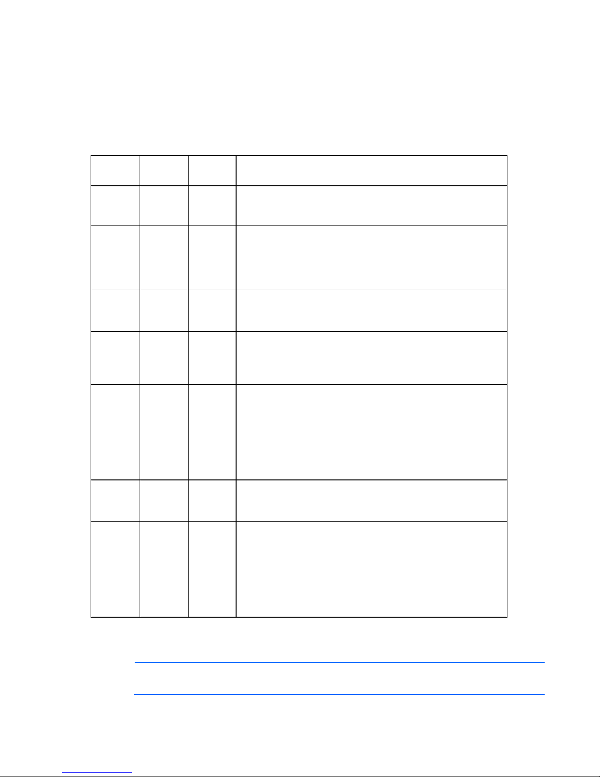
Hard drive LED combinations
Hot-plug SCSI hard drive LED combinations
Activity
LED (1)
On, off,
or
flashing
On, off,
or
flashing
On or
flashing
On Off Off Do not remove the drive.
Flashing Flashing Flashing
Off Off On
Off Off Off One or more of the following conditions may exist:
Online
LED (2)
On or off Flashing A predictive failure alert has been received for this drive.
On Off The drive is online and is configured as part of an array.
Flashing Off
Fault
LED (3)
Interpretation
Replace the drive as soon as possible.
If the array is configured for fault tolerance and all other drives in
the array are online, and a predictive failure alert is received or a
drive capacity upgrade is in progress, you may replace the drive
online.
Do not remove the drive. Removing a drive may terminate the
current operation and cause data loss.
The drive is rebuilding or undergoing capacity expansion.
The drive is being accessed, but (1) it is not configured as part of
an array; (2) it is a replacement drive and rebuild has not yet
started; or (3) it is spinning up during the POST sequence.
Do not remove the drive. Removing a drive may cause data loss in
non-fault-tolerant configurations.
One or more of the following conditions may exist:
The drive is part of an array being selected by an array
configuration utility
Drive Identification has been selected in HP SIM
The drive firmware is being updated
The drive has been placed offline due to hard disk drive failure or
subsystem communication failure.
You may need to replace the drive.
The drive is not configured as part of an array
The drive is configured as part of an array, but it is a
replacement drive that is not being accessed or being rebuilt yet
The drive is configured as an online spare
If the drive is connected to an array controller, you may replace the
drive online.
SAS and SATA hard drive LED combinations
NOTE: Predictive failure alerts can occur only when the server is connected to a Smart Array
controller.
Common problem resolution 20
Online/activity
LED (green)
On, off, or
flashing
On, off, or
flashing
On
On Off The drive is online, but it is not active currently.
Flashing regularly
(1 Hz)
Flashing regularly
(1 Hz)
Flashing
irregularly
Flashing
irregularly
Off Steadily amber
Off
Off Off
Fault/UID LED
(amber/blue)
Alternating amber
and blue
Steadily blue
Amber, flashing
regularly (1 Hz)
Amber, flashing
regularly (1 Hz)
Off
Amber, flashing
regularly (1 Hz)
Off The drive is active, and it is operating normally.
Amber, flashing
regularly (1 Hz)
Interpretation
The drive has failed, or a predictive failure alert has been
received for this drive; it also has been selected by a
management application.
The drive is operating normally, and it has been selected by a
management application.
A predictive failure alert has been received for this drive.
Replace the drive as soon as possible.
Do not remove the drive. Removing a drive may terminate the
current operation and cause data loss.
The drive is part of an array that is undergoing capacity
expansion or stripe migration, but a predictive failure alert has
been received for this drive. To minimize the risk of data loss,
do not replace the drive until the expansion or migration is
complete.
Do not remove the drive. Removing a drive may terminate the
current operation and cause data loss.
The drive is rebuilding, erasing, or it is part of an array that is
undergoing capacity expansion or stripe migration.
The drive is active, but a predictive failure alert has been
received for this drive. Replace the drive as soon as possible.
A critical fault condition has been identified for this drive, and
the controller has placed it offline. Replace the drive as soon as
possible.
A predictive failure alert has been received for this drive.
Replace the drive as soon as possible.
The drive is offline, a spare, or not configured as part of an
array.
Server updates with an HP Trusted Platform Module
and BitLocker™ enabled
When a TPM is installed and enabled in RBSU, and when the Microsoft® Windows® BitLocker™ Drive
Encryption feature is enabled, always disable BitLocker™ before performing any of the following
procedures:
• Restarting the computer for maintenance without a PIN or startup key
• Updating firmware (on page 82)
• Upgrading critical early boot components
• Upgrading the system board to replace or remove the TPM
• Disabling or clearing the TPM
Common problem resolution 21

• Moving a BitLocker™-protected drive to another server
• Adding an optional PCI device, such as a storage controller or network adapter
Common problem resolution 22

Diagnostic flowcharts
Troubleshooting flowcharts
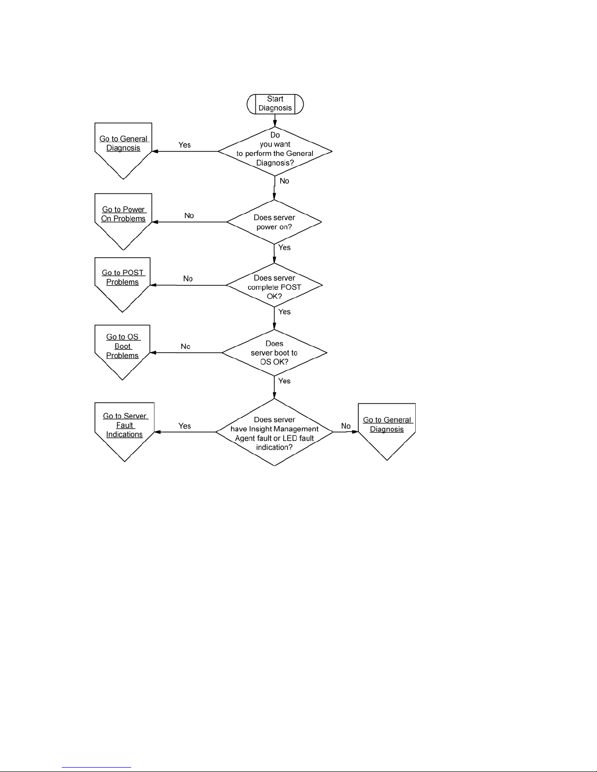
To effectively troubleshoot a problem, HP recommends that you start with the first flowchart in this section,
"Start diagnosis flowchart (on page 25)," and follow the appropriate diagnostic path. If the other
flowcharts do not provide a troubleshooting solution, follow the diagnostic steps in "General diagnosis
flowchart (on page 25)." The General diagnosis flowchart is a generic troubleshooting process to be used
when the problem is not server-specific or is not easily categorized into the other flowcharts.
The available flowcharts include:
• Start diagnosis flowchart (on page 25)
• General diagnosis flowchart (on page 25)
• Power-on problems
o Server power-on problems flowchart (on page 27)
o p-Class server blade power-on problems flowchart (on page 29)
o c-Class server blade power-on problems flowchart (on page 29)
• POST problems flowchart (on page 30)
o Server and p-Class server blade POST problems flowchart (on page 31)
o c-Class server blade POST problems flowchart
• Operating system boot problems flowchart
• Server fault indications flowchart (on page 33)
o Server and p-Class server blade fault indications flowchart (on page 34)
o c-Class server blade fault indications flowchart
Troubleshooting flowchart reference websites
Each flowchart contains references to external websites. The following websites correspond to the
numbered websites in each flowchart:
1. HP Technical Support (http://www.hp.com/support)
Select your country and then follow the instructions to locate software, firmware, and drivers.
2. HP ProLiant maintenance and service guides:
o Business Support Center (http://www.hp.com/go/bizsupport)
Select Manuals. Under Servers, select ProLiant and tc series servers. Select the product, and then
locate the link for the maintenance and service guide.
o HP BladeSystem p-Class Support and Documents
(http://www.hp.com/products/servers/proliant-bl/p-class/info
)
Diagnostic flowcharts 23

Under Product support, select the product. Select Manuals (guides, supplements, addendums,
etc). Under Service and maintenance information, locate the link for the maintenance and service
guide.
o HP BladeSystem c-Class Technical Documentation
(http://www.hp.com/go/bladesystem/documentation
)
Select Support, Drivers and Manuals, and then select the product. Select Manuals, and then
locate the link for the maintenance and service guide.
3. HP BladeSystem p-Class Support and Documents (http://www.hp.com/products/servers/proliant-
bl/p-class/info)
To locate the HP BladeSystem p-Class System Maintenance and Service Guide, select the product.
Select Manuals (guides, supplements, addendums, etc). Under Service and maintenance information,
locate the link for the document.
4. HP BladeSystem Power Sizer (http://www.hp.com/go/bladesystem/powercalculator)
Use the Power Sizer to plan your power infrastructure and meet the needs of an HP BladeSystem
solution.
5. Remote management (http://www.hp.com/servers/lights-out)
To locate the Integrated Lights-Out User Guide, select the product, and then select Support &
Documents. Select Manuals and locate the link to the document.
6. SmartStart Support and Documents (http://www.hp.com/support/smartstart/documentation)
In the User guides section, locate the link for the HP ROM-Based Setup Utility User Guide.
7. System Management homepage (https://localhost:2381)
Access consolidated system management information.
Diagnostic flowcharts 24
Start diagnosis flowchart
Use the following flowchart to start the diagnostic process.
General diagnosis flowchart
Diagnostic flowcharts 25
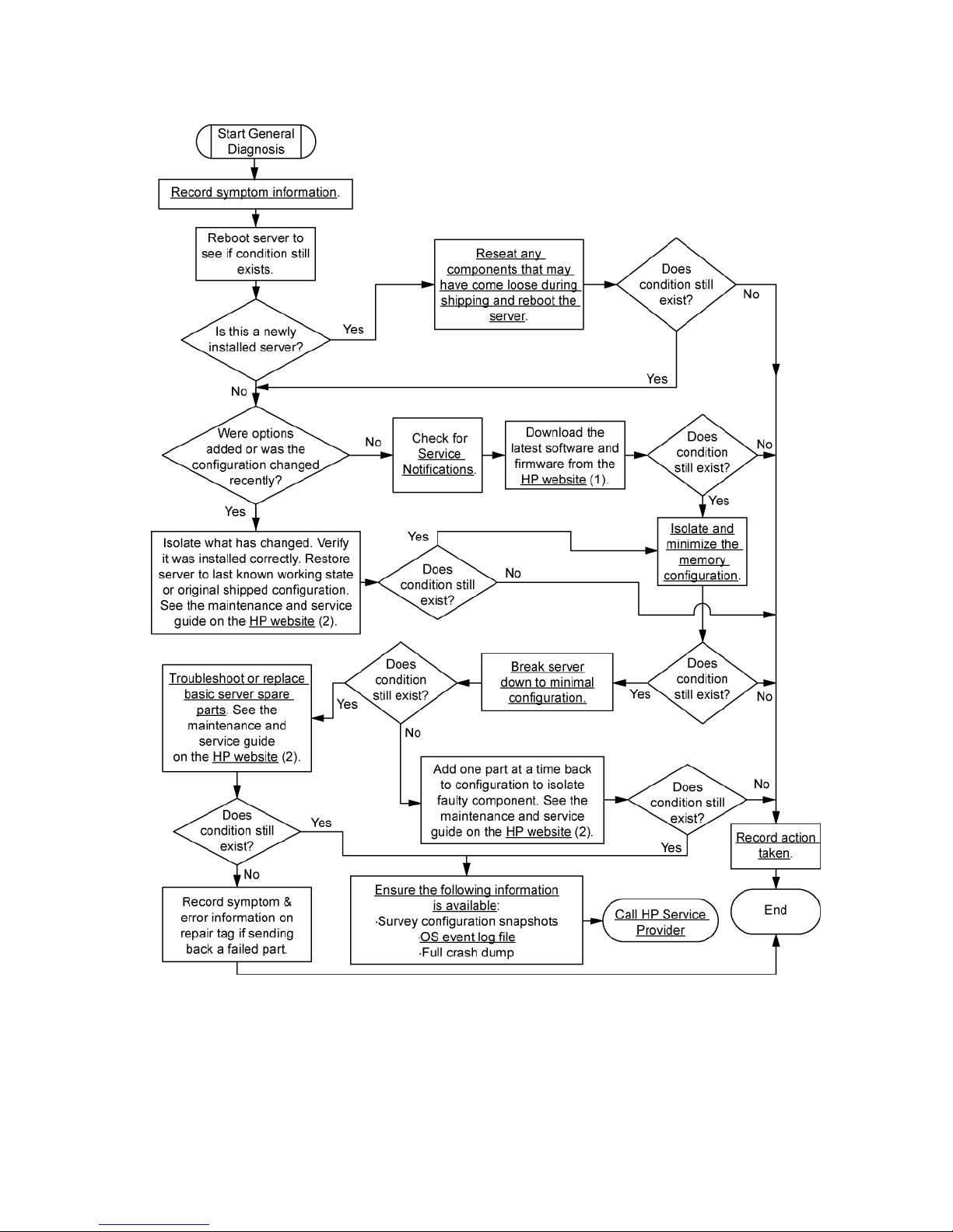
The General diagnosis flowchart provides a generic approach to troubleshooting. If you are unsure of the
problem, or if the other flowcharts do not fix the problem, use the following flowchart.
Diagnostic flowcharts 26

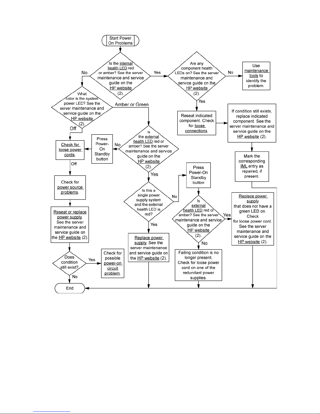
Power-on problems flowchart
Server power-on problems flowchart
Some servers have an internal health LED and an external health LED, while other servers have a single
system health LED. The system health LED provides the same functionality as the two separate internal and
external health LEDs. Depending on the model, the internal health LED and external health LED may either
appear solid or they may flash. Both conditions represent the same symptom.
For the location of server LEDs and information on their statuses, see the server documentation on the HP
website (http://www.hp.com/support
Symptoms:
• The server does not power on.
• The system power LED is off or amber.
• The external health LED is red, flashing red, amber, or flashing amber.
• The internal health LED is red, flashing red, amber, or flashing amber.
• The system health LED is red, flashing red, amber, or flashing amber.
).
Possible causes:
• Improperly seated or faulty power supply
• Loose or faulty power cord
• Power source problem
• Improperly seated component or interlock problem
Diagnostic flowcharts 27
Diagnostic flowcharts 28
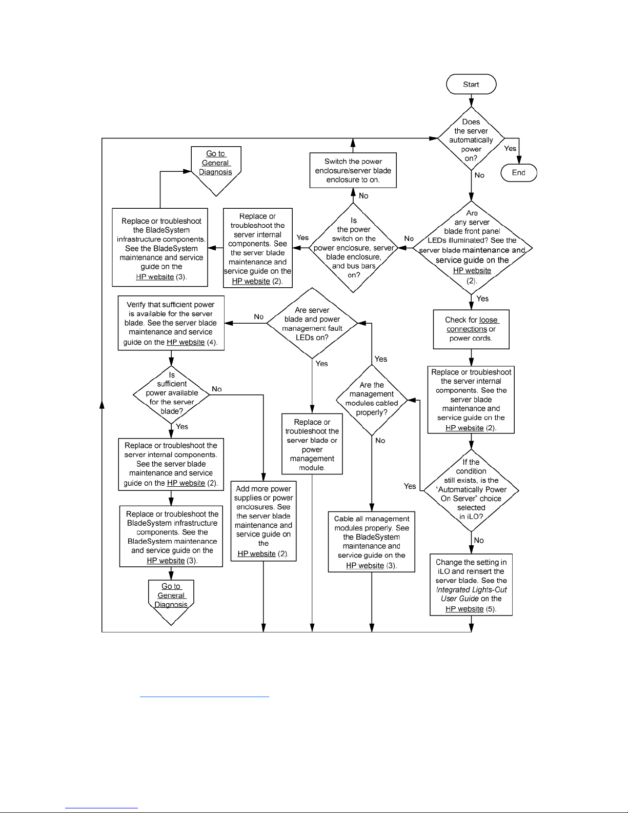
p-Class server blade power-on problems flowchart
c-Class server blade power-on problems flowchart
For the location of server LEDs and information on their statuses, see the server documentation on the HP
website (http://www.hp.com/support
Symptoms:
• The server does not power on.
).
Diagnostic flowcharts 29
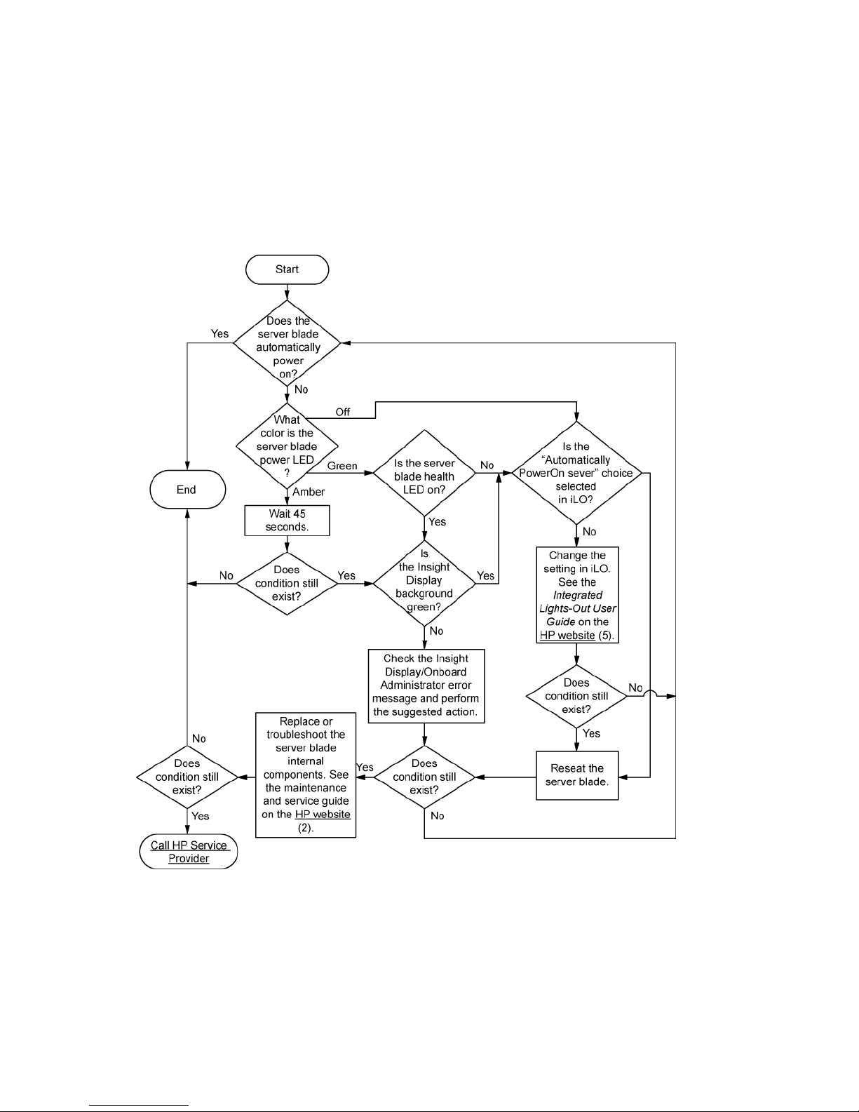
• The system power LED is off or amber.
• The health LED is red or amber.
Possible causes:
• Improperly seated or faulty power supply
• Loose or faulty power cord
• Power source problem
• Improperly seated component or interlock problem
POST problems flowchart
Symptoms:
• Server does not complete POST
Diagnostic flowcharts 30
 Loading...