

Hp PHOTOSMART R827 User Manual [sk]

SANworks by Compaq
Application Notes –
HSG80 ACS Version 8.6-4P Data Replication Manager Design Guide
Part Number: AA–RQ78A-TE
First Edition (February 2002)
Product Version: ACS Version 8.6-4P
This document provides design assistance for Compaq customers, as well as for field and reseller presales
technical support staff, for supportable SANworks
design guide provides help by discussing the different design tradeoffs and by providing a checklist of
required solution hardware and software components, based on the results of the design process.
For the latest version of these Application Notes and other DRM documentation, visit the Compaq storage
website at: http://www.compaq.com/products/sanworks/drm/index.html.
TM
Data Replication Manager by Compaq solutions. This
b

© 2002 Compaq Information Technologies Group, L.P.
Compaq, the Compaq logo, ProLiant, SANworks, StorageWorks, Tru64, OpenVMS, and TruClusters are
trademarks of Compaq Information Technologies Group, L.P. in the U.S. and/or other countries.
Microsoft, Windows, and Windows NT are trademarks of Microsoft Corporation in the U.S. and/or other
countries.
UNIX is a trademark of The Open Group in the U.S. and/or other countries.
All other product names mentioned herein may be trademarks of their respective companies.
Confidential computer software. Valid license from Compaq required for possession, use or copying. Consistent
with FAR 12.211 and 12.212, Commercial Computer Software, Computer Software Documentation, and
Technical Data for Commercial Items are licensed to the U.S. Government under vendor's standard commercial
license.
Compaq shall not be liable for technical or editorial errors or omissions contained herein. The information is
provided “as is” without warranty of any kind and is subject to change without notice. The warranties for
Compaq products are set forth in the express limited warranty statements accompanying such products. Nothing
herein should be construed as constituting an additional warranty.
Compaq service tool software, including associated documentation, is the property of and contains confidential
technology of Compaq Computer Corporation or its affiliates. Service customer is hereby licensed to use the
software only for activities directly relating to the delivery of, and only during the term of, the applicable services
delivered by Compaq or its authorized service provider. Customer may not modify or reverse engineer, remove,
or transfer the software or make the software or any resultant diagnosis or system management data available to
other parties without Compaq’s or its authorized service provider’s consent. Upon termination of the services,
customer will, at Compaq’s or its service provider’s option, destroy or return the software and associated
documentation in its possession.
Printed in the U.S.A.
Application Notes – HSG80 ACS Version 8.6-4P Data Replication Manager Design Guide
First Edition (February 2002)
Part Number: AA–RQ78A-TE
2 Application Notes – HSG80 ACS Version 8.6-4P Data Replication Manager Design Guide

Application Notes Contents
These Application Notes cover the following major topics:
• Other Documentation, page 4
• Introduction, page 4
• DRM Overview, page 4
— Supported Hardware and Software, page 5
• Design Tradeoffs, page 6
— Business Requirements, page 6
— High Availability, page 7
— Threat Radius, page 7
— Disaster Tolerance, page 9
— Physics of Distance, page 9
— Synchronous versus Asynchronous Replication, page 13
— Bidirectional Solution, page 14
Application Notes Contents
— Determining Write-to-Disk Rate, page 15
• DRM Storage Design Considerations, page 16
— Disaster-Tolerant LUNs, page 16
— Non-Disaster-Tolerant LUNs, page 16
— Array Limits, page 16
— Fabric Port Count Results, page 17
— Failover Requirements Planning, page 17
• DRM Configurations, page 18
— Basic DRM-over-Fiber, page 18
— Long Distance Solutions, page 21
— Special-Purpose DRM Solutions, page 26
• Checklist for Supportable Solution Configuration Confirmation, page 30
— Basic DRM or DRM-over-WDM Configurations, page 30
— DRM Fibre Channel over ATM Configurations, page 33
— DRM Fiber Channel over IP Configurations, page 35
• Glossary, page 38
Application Notes – HSG80 ACS Version 8.6-4P Data Replication Manager Design Guide 3

Introduction
Other Documentation
This document references the following related Compaq documents:
• SANworks by Compaq Data Replication Manager HSG80 ACS Version 8.6-4P Failover/Failback
Procedures Guide, part number AA-RPJOC-TE
• SANworks by Compaq Data Replication Manager HSG80 ACS Version 8.6-4P Configuration
Guide, part number AA-RPHZC-TE
• SANworks by Compaq Data Replication Manager HSG80 ACS Version 8.6-1P Scripting User
Guide, part number EK-DRMSC-OA. C01
• SANworks by Compaq Application Notes - Data Replication Manager Over an Internet Protocol
Intersite Link, part number EK-DRMIP-AA. A01
• Compaq SANworks Application Notes - Data Replication Manager Using Very Long Distance
GBICs, part number EK-DRMLD. C01
• Compaq SANworks Application Notes - Data Replication Manager over an ATM Link Supporting
OSG Version 2.2.5, part number EK-DRMAL-AA. F01
• Compaq SANworks Application Notes - Data Replication Manager Over a WDM-enabled Intersite
Link, part number EK-DRMWD-AA. A01
• Compaq StorageWorks Heterogeneous Open SAN Design Reference Guide, part number
AA-RMPNC-TE
• Compaq Features and Benefits of ACS 8.6P Data Replication Manager white paper, part number
1653-1202A-WWEN
• Compaq SANworks Data Replication Manager Inter-site Link Performance Analyzer Calculation
Tool
These documents, along with additional Compaq documentation, including white papers and best
practices documents, are available via the Compaq website at:
http://www.compaq.com/products/sanworks/drm/index.html.
Introduction
This document is designed to help customers of Compaq Computer Corporation, as well as field and
reseller presales technical support staff, design supportable SANworks
Compaq solutions.
To accomplish this goal, these Application Notes review how the Data Replication Manager (DRM)
works, and provide several DRM solution design tradeoff discussions. For each of the possible
solutions, the “DRM Configurations” section includes configuration rules and the data needed to build
a basic bill of materials for any configuration based on the supported solution.
DRM Overview
DRM is a controller-based data replication software solution for disaster tolerance and data movement.
DRM works with the StorageWorks™ by Compaq Fibre Channel MA8000/EMA12000/EMA16000
and RA8000/ESA12000 storage systems.
TM
Data Replication Manager by
DRM allows all data to be mirrored between storage elements in two different storage arrays that can
be in separate geographical locations. Each write I/O is sent to both storage locations, and reads occur
only at the local storage. Properly configured, DRM can be a complete disaster-tolerant storage
solution that guarantees data integrity in case of a storage subsystem or site failure.
4 Application Notes – HSG80 ACS Version 8.6-4P Data Replication Manager Design Guide
DRM Overview
DRM copies data online and in real time to remote locations through a local or extended storage area
network (SAN). For more about the features and benefits of DRM, refer to the Compaq Features and
Benefits of ACS 8.6P Data Replication Manager white paper.
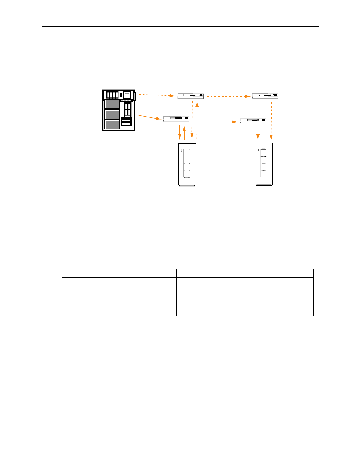
A basic DRM configuration is shown in Figure 1.
Server
Figure 1: SANworks Data Replication Manager basic configuration
Supported Hardware and Software
Table 1 details the hardware and operating systems supported by DRM as of the time this document
was published. Refer to the DRM website for a current list of supported hardware and operating
system versions:
http://www.compaq.com/products/sanworks/drm/index.html
Switch
Initiator
Switch
Switch
Switch
Target
Table 1: DRM-Supported Host Servers/Operating Systems
Host Server Supported Operating System
Compaq AlphaServer™
Compaq Proliant™ Server
Hewlett-Packard HP9000—L, N, V Class
IBM—RS6000
Sun—Ultra SPARC
OpenVMS™ , Tr u6 4 ™ UNIX
Novell NetWare, Windows 2000, Windows NT
HP-UX
AIX
Solaris
Table 2 lists the supported operating systems by version and the SCSI command level that each
operating system supports. Additional information on sharing of Compaq storage subsystems is
available in the Compaq StorageWorks Heterogeneous Open SAN Design Reference Guide. Other
supported operating systems and specific versions may be available from the Compaq Custom Systems
Group.
Application Notes – HSG80 ACS Version 8.6-4P Data Replication Manager Design Guide 5

Design Tradeoffs
Table 2: DRM-Supported Operating System Versions
Operating System Supported Version
Compaq OpenVMS V 7.2-2, 7.3
• VMS Clusters appropriate to OS version
Compaq Tru64 UNIX V5.1, 5.1a
• TruClusters appropriate to OS version
Hewlett-Packard
HP-UX
IBM AIX V4.3.3
Microsoft Windows
2000 for Server,
Advanced Server,
Datacenter Server
Microsoft Windows
NT Server
Novell NetWare V5.1, 6.0
SUN Solaris 2.6 (32-bit mode only)
V11.0
• HP MC/Service Guard Clusters VA.11.12
• Cluster Object Manager VA.01.01
• Secure Path for HP-UX V3.0
• HACMP Clusters V4.4.0
• Secure Path for AIX V2.0A
• Service Pack 2
• MSCS V1.1
• Secure Path for Windows V3.1A with SP1
V4.0
• Service Pack 6a with hotfix
• MSCS V1.1
• Secure Path for Windows V3.1A with SP1
• Secure Path for Novell V3.0B
7, 8 (32- and 64-bit mode)
• Secure Path for SUN V2.1D, 3.0
• VERITAS Clusters V1.3
• SUN Clusters V2.2
SCSI-2
Support
No Yes
Ye s Ye s
Ye s Ye s
Ye s Ye s
Ye s Ye s
Ye s Ye s
Ye s Ye s
Yes Yes (V7, 8)
SCSI-3
Support
No (V2.6)
DRM supports the ability of compatible operating systems to share the same controller. To be
compatible, all the operating systems must support the same level of SCSI command and control.
Design Tradeoffs
The following sections describe tradeoffs that need to be considered when you design a DRM solution.
Business Requirements
The first step in designing a data replication solution is to understand what is driving the need for it. In
some cases, there is a business need for high availability, and disaster tolerance is seen as a side
benefit. In other cases, there is a business requirement for disaster-tolerant data, with high availability
of the applications being viewed as a side benefit. Neither configuration, however, satisfies both
requirements without additional hardware or software. DRM provides disaster-tolerant data, while
clustering technology (such as VMSClusters, TruClusters, Service Guard Clusters, HACMP, MSCS,
VERITAS Clusters, and SUN Clusters) supports high availability of applications. Together, these
solutions provide highly available applications with disaster-tolerant data.
6 Application Notes – HSG80 ACS Version 8.6-4P Data Replication Manager Design Guide

High Availability
DRM provides highly available and reliable access to data, but because it is a storage-centric solution,
it does not provide highly available applications. To achieve highly available applications, standby
servers are needed to provide the processing platforms used by the applications if the primary system
fails.
Customers can deploy a cluster of servers at the primary site, with either a single backup server or
cluster of servers at the remote site. The resulting configuration provides highly available and
disaster-tolerant applications and data. In addition, DRM can function in both directions between sites
to optimize the use of the equipment.
Table 3 shows the importance of high availability. Note that even at an availability of 99%, an
application could be down for nearly 4 days per year.
Table 3: Real-world Availability: Outage Minutes per Year
Design Tradeoffs
Availability
Outage Minutes
per Year
Table 4 illustrates expected user outage minutes per year for several server types.
Table 4: User Outage Minutes and Relative Availability
User Outage
Minutes per
User Year
Relative
Availability
Threat Radius
The threat radius is the distance from the center of a threat to the outside perimeter of that threat. For
example, half the diameter of a hurricane or typhoon is the threat radius of that storm. Another
example might be where a chemical factory is at the center of the threat radius circle. The threat radius
is defined by the downwind distance of danger if there is a leak of hazardous chemicals.
90% 95% 99% 99.9% 99.99% 99.999% 100%
50,000 25,000 5,000 500 50 5 0
Windows NT
Windows NT
Server
8,200 3,150 1,150 180
46 times less
reliable than
Himalaya
Windows NT
Server & MSCS
18 times less
reliable than
Himalaya
Server & MSCS &
NonStop Software
6 times less
reliable than
Himalaya
NonStop Himalaya
OS & NonStop
Software
1x
The three general classes of threat in a DRM solution are local, within the metropolitan area, and
regional. These three classes make it easier to characterize the solution in terms of intersite link
options, performance, and system reliability. These three types of threats are defined as follows:
Local—Any threat that is less than a few kilometers in radius (less than 25 square kilometers), such as
a tornado or a plant fire, is a local threat. Local replication has the least impact on performance as
compared to the other options.
Metropolitan—Any threat that is larger than a local threat, and which might extend from 25 square
kilometers to 5,000 square kilometers, such as a large chemical incident, a moderate earthquake, or a
severe storm, is considered a metropolitan threat. Replication outside of metropolitan threats is similar
in performance cost to running older disk drives—it is slower but acceptable.
Application Notes – HSG80 ACS Version 8.6-4P Data Replication Manager Design Guide 7

Design Tradeoffs
Regional—Any disaster that affects a radius of hundreds of kilometers to tens of thousands of
kilometers, such as a large flood or hurricane, is considered a regional disaster. By sheer size, the
regional disaster requires the largest separation distance when planning disaster-tolerant solutions.
Depending on the distances, data replication to the outside of a regional disaster threat radius will
impact system performance. However, separation distances of more than 1,000 kilometers are rarely
needed and only increase the cost of the link, rather than provide additional disaster tolerance.
In review, local disasters usually do not exceed a threat radius of a few kilometers. A metropolitan
disaster covers threats with a radius greater than a few kilometers to tens of kilometers. The typical
regional disaster covers hundreds of kilometers.
Examples of each disaster include:
• Building fire: local.
• Tornado: local, but possibly metropolitan if it stays on the ground for a long time.
• Hurricane/typhoon: metropolitan to regional, depending on size and intensity.
• Floods: local to regional along the flood plain.
• Earthquake: usually local to metropolitan, depending on severity.
• Environmental: local.
• Power loss: local to regional, depending on which component fails—a local distribution point or a
major portion of the regional power grid.
In considering the threat radius, planners must decide what the threats are to the primary system, and
whether those threats also apply to the backup system. For example, it would be unwise to place both
sites in the same flood plain because one flood could destroy both. Similarly, if severe storms tend to
travel in a certain direction, then a good strategy would be to place the two sites perpendicular to the
expected route of travel and as far apart as possible to prevent one storm from affecting both sites.
Figure 2 is an example of the relative relationship between the three classes of threats based on the
radius of those threats.
Local (few km)
Regional (100s km)
Metropolitan (10s km)
Figure 2: Threat radius
8 Application Notes – HSG80 ACS Version 8.6-4P Data Replication Manager Design Guide
Disaster Tolerance
Disaster tolerance is the ability of a system to withstand a defined disaster, such as being outside the
threat radius for that potential disaster. DRM enables applications to automatically and continuously
build two copies of application data at geographically separated sites.
The larger the potential disaster (threat radius), the farther apart the primary and backup sites need to
be. To determine an adequate distance, first determine what kinds of disasters are probable in the local
area and understand the protection distances needed to separate the two sites. Consider any local
regulatory requirements that might increase or limit the separation distance. For example, some
counties in the United States require both sites to remain within the same 100 to 400 sq. km county.
This restriction has limited the maximum separation distance to less than 30 km in an area prone to
earthquakes. Such earthquakes have impacted buildings several hundred kilometers from the
earthquake's epicenter.
On the east coast of the United States, and the southern and eastern coasts of the Asian subcontinent,
hurricanes or typhoons can cover an area with a radius of 200 km or more. Other natural disasters
include regional forest fires, localized tornadoes, and widespread flooding. Non-natural disasters
include building fires or chemical contamination, either of which can limit access to computer
facilities.
In order to deal with the types and scope of potential disasters, storage system planners must consider
this tradeoff—with increasing distance comes lower performance.
Design Tradeoffs
Physics of Distance
A data replication product can move data at extreme distances, but due to propagation delays inherent
in data transfers, it may take a long time for each replication I/O to be completed. The distance
between the two sites, not the width of the pipe, is the limiting factor in replication performance. This
section provides a brief overview of the impact of distance on the sustainable I/O rate.
S
i
t
e
A
Figure 3: Impact of distance on I/O rate
In Figure 3 there are two I/O pipes: one narrow arrow representing a slow communications channel,
and a wider arrow representing a high-speed intersite link. Both I/O packets (shown by the
parallelograms) contain the same amount of data. They are moving from Site A to Site B (left to right),
and the leading edge of both will arrive at Site B at the same time. The difference in pipe size
(bandwidth of the link) allows the faster pipe to complete delivery of the packet before the slower pipe.
The difference is that the wider pipe provides shorter times to load and unload the packet. At long
distances, the communications bandwidth becomes a less important factor in determining the I/O rate.
S
i
t
e
B
Application Notes – HSG80 ACS Version 8.6-4P Data Replication Manager Design Guide 9

Design Tradeoffs
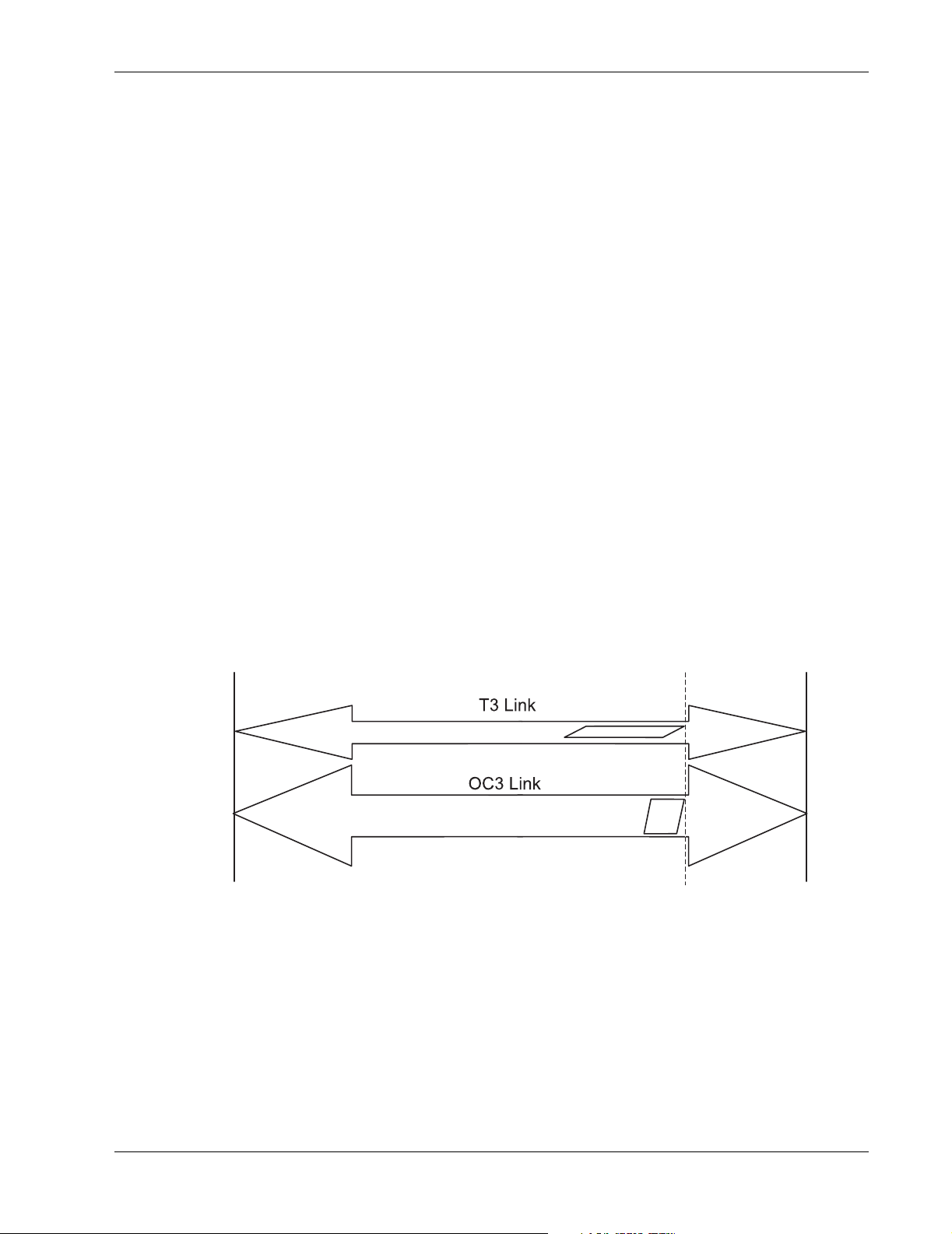
The time required to load or unload a packet can be approximated using the bandwidth of the pipe and
the size of the packet. For example, given a 16-KB packet and a T1 transmission speed of 1.54 Mbps,
it takes approximately 0.1 seconds to load the packet onto the link. Using a Fibre Channel link running
at 1,000 Mbps and the same 16-KB data packet, the time is reduced to 0.00016 seconds.
Table 5 provides the data for calculating how long it takes to complete a single I/O across a zero
distance intersite link, based on the link bandwidth and the size of the data packet. The columns are the
transmission technology, performance or bandwidth of common intersite links, the slope (m) of the
line that approximates the time it takes to load the data onto a given pipe, and the Y-intercept (b)
representing the replication and conversion overhead.
Enter the size of the data packet (X) in kilobytes and calculate the zero distance I/O completion times
(Y) as follows:
Y (in milliseconds) = mX+b
Note that intercept (b) represents the minimum amount of time it takes to load one 512-byte data
packet onto the intersite link. In addition, the slope (m) of the line represents the amount of additional
time it takes to insert ever larger data packets onto the intersite link.
L
Table 5: Link Performance Table
Fibre Channel 1000 0.056 0.84
1-GbE (Gigabit Ethernet) IP 1000 0.056 0.84
OC3-ATM 155 0.134 1.8
100-Mbit IP 100 0.134 1.8
100-Mbit IP with very high compression 100 0.056 0.84
T3-ATM 44 0.32 2.8
10-Mbit IP 10 1.02 3.0
10-Mbit IP with very high compression 10 0.134 1.8
Intersite Link Technology
Intersite Link Bandwidth
(Mbps) Slope (m) Intercept (b)
NOTE: m = a number proportional to the amount of time it takes to send larger packets
versus smaller packets.
b = the replication overhead—the amount of time it takes to replicate one 512-byte block.
The second factor in determining how long it takes to complete a single I/O over distance is the time it
takes for the leading edge of the data to travel from one end of the link to the other. This time can be
estimated using a speed of 200,000,000 m/s for light in standard fiber-optic cable, which equates to 5
microseconds per kilometer. For an intersite separation distance of 10,000 km, the time interval would
be 50,000 microseconds or 0.05 seconds, and is 25 times the average rotational latency of a 15,000 rpm
disk drive (which is 0.002 seconds).
DRM implementation of the FC-defined SCSI protocol requires four trips through the intersite link to
complete a single write. First, the SCSI initiator must ask the SCSI target if it is ready to accept data.
Second, the SCSI target indicates it is ready. Then, the SCSI initiator sends the data to the target. The
final trip occurs when the SCSI target replies that it has received the data. The true time it takes to
move data from the initiator controller to the target controller is four times the single-trip distance, plus
the time it takes to load the data for a given pipe size. These four trips, consisting of three small control
packets and one large data packet, equate to 20 microseconds of latency per kilometer of intersite link
distance to complete the SCSI write. Based on the distance between the two sites, this latency is added
to the previously calculated time to complete a zero distance I/O.
10 Application Notes – HSG80 ACS Version 8.6-4P Data Replication Manager Design Guide

Two methods are used to calculate the intersite latency based on the cable distance between the two
sites. One is based on the driving distance, the other on the network latency. If an intersite network
exists, use the more accurate network latency as the metric. If an intersite network does not exist, then
use the driving distance approach.
Driving Distance
To estimate the cable distance between two sites, measure the distance by driving a car between the
two sites. For point-to-point networks, multiply the driving distance by 1.5. For routed networks,
multiply the driving distance by 2.25. For example, if two sites are located 150 km apart, the estimated
cable distance for a point-to-point network would be 225 km.
Network Latency
If an intersite network connection exists, ask the network engineers for an estimate of the one-way or
round-trip intersite latency. In the preceding example, the actual point-to-point network was measured
to give one-way latency of approximately 5 milliseconds or 250 km, instead of the 225 km originally
estimated by using driving distance.
Single Stream I/O Example
DRM invokes a process called normalization whenever a remote copy set (RCS) is created. The remote
copy set function allows data to be copied (mirrored) from the initiator site to a target site. The result is
mirrored data at two disparate sites. During the normalization process, data is copied from the initiator
side of the logical unit to the target side of the RCS. Each write copies 128 blocks of 512 bytes (or 64
KB of data) from the initiator to the target. To prevent overwhelming the system, only one write per
RCS is allowed to be outstanding. This is defined as a single synchronous I/O stream.
Design Tradeoffs
For the purpose of this example, assume that the two sites are located 100 km apart and that the RCS
consists of two 9-GB disk drives, one at each site.
Table 6 provides the calculation results for loading 64 kilobytes of data onto the different links.
Table 6: Calculation of Time to Load Data onto an Intersite Link
Technology Slope Time to Load 64 KB of Data (ms)
Direct FC or GbE 0.056 3.58
FC/ATM OC-3 or 100 Mbps 0.134 8.58
FC/ATM T3 0.32 20.48
FC/IP 10-Mbit with no compression 1.02 65.28
Given the intersite distance of 100 km, the transfer latency is 100 x 20 microseconds/km =
2 milliseconds, and is approximately the same for all interconnects.
Table 7 provides the calculation for adding the two results together, plus the replication overhead.
Table 7: Calculation Time to Complete a Single I/O Over Distance
+ Intersite
Technology Time to Load (ms)
Direct FC or GbE 3.58 2 0.84 6.42
FC/ATM OC-3 or
100 Mbps
FC/ATM T3 20.48 2 2.8 25.28
FC/IP 10 Mbps 65.28 2 3.0 70.28
8.58 2 1.8 12.38
Latency (ms) + Overhead (ms)
= Time to
Complete I/O (ms)
Application Notes – HSG80 ACS Version 8.6-4P Data Replication Manager Design Guide 11

Design Tradeoffs
Inverting the time-to-complete number (milliseconds per I/O) produces an approximate number of
single-stream synchronous writes that can be completed every second for the various bandwidths of
pipes for the example distance. The results are shown in Table 8 as approximate times needed to
normalize a 9-GB logical unit number (LUN).
Table 8: Relationship of I/O Per Second to Throughput and Time to Normalize a 9-GB LUN
Approximate I/O
Technology
Direct FC or GbE 155.7 35.87 GB per hour 0.25 hour
FC/ATM OC-3 or 100 Mbps 80.8 18.62 GB per hour 0.48 hour
FC/ATM T3 39.6 9.11 GB per hour 0.98 hour
FC/IP 10 Mbps 14.2 3.28 GB per hour 2.75 hours
You can also use the Compaq SANworks Data Replication Manager Inter-site Link Performance
Analyzer Calculation Tool to perform these same calculations.
Multiple I/O Streams for a Single Application
After determining the worst case for the time duration to perform the replication of a single write, you
must examine the impact of multiple I/O streams from a single application. Multiple writes can be
replicated at the same time, as shown in Figure 4. The wider the pipe, the more writes it can hold, up to
a maximum called the bandwidth-latency product. Multiply the net performance of the
communications pipe (total bits per second, less any overhead) times the intersite latency in seconds.
This number, when expressed in bytes (use 10 bits per byte) and divided by the average message size
(in bytes), determines the average number of messages that can be in the communications pipe at one
time.
In Figure 4, the parallelograms represent two I/O streams. Each I/O stream consists of data packets of
equal size (same number of bytes). The narrow pipe is able to hold only three packets, but the wider
pipe is able to hold nine packets.
per Second
Throughput (Based
on 64KB per I/O)
Approximate Time Required
to Normalize a 9-GB LUN
S
i
t
e
A
Figure 4: The impact of multiple I/O streaming for single applications
Two other constraints will further limit the maximum number of I/O streams in the pipe. The first limit
is the number of Fibre Channel buffer-to-buffer credits allowed between any Fibre Channel devices.
Using Brocade Fibre Channel switches running firmware V2.1.9m, this number is currently defaulted
at 16, for 16 open message exchanges. This limit is seen on any long distance direct Fibre Channel
connection with very long distance Gigabit Interface Converters (GBICs) or wavelength division
multiplexing (WDM) solution. It is not usually seen in DRM-over-ATM or DRM-over-IP because the
credit is returned by the ATM or IP gateway to the sending switch.
S
i
t
e
B
12 Application Notes – HSG80 ACS Version 8.6-4P Data Replication Manager Design Guide
 Loading...