

Page 1

HP Performance-Optimized Datacenter User Guide
Part Number 510055-001
March 2009 (First Edition)
Page 2

© Copyright 2009 Hewlett-Packard Development Company, L.P.
The information contained herein is subject to change without notice. The only warranties for HP products and services are set forth in the express
warranty statements accompanying such products and services. Nothing herein should be construed as constituting an additional warranty. HP
shall not be liable for technical or editorial errors or omissions contained herein.
Confidential computer software. Valid license from HP required for possession, use or copying. Consistent with FAR 12.211 and 12.212,
Commercial Computer Software, Computer Software Documentation, and Technical Data for Commercial Items are licensed to the U.S.
Government under vendor’s standard commercial license.
Microsoft, Windows, and Windows Server are U.S. registered trademarks of Microsoft Corporation. Intel, Pentium, and Itanium are trademarks
or registered trademarks of Intel Corporation or its subsidiaries in the United States and other countries. UNIX is a registered trademark of The
Open Group.
Intended audience
This document is for the person who installs, administers, and troubleshoots servers and storage systems. HP assumes you are qualified in the
servicing of computer equipment and trained in recognizing hazards in products with hazardous energy levels.
Page 3

Contents
Site requirements .......................................................................................................................... 6
Optimum environment................................................................................................................................6
Location considerations ....................................................................................................................6
Moving the HP POD ........................................................................................................................ 6
System utilities.................................................................................................................................6
Transformer, switchboard, and water distribution kit locations ............................................................... 7
Work space requirements.................................................................................................................8
Environmental considerations...................................................................................................................... 8
Temperature considerations ..............................................................................................................8
Leveling requirements.......................................................................................................................9
Grounding requirements...................................................................................................................9
Lightning protection .........................................................................................................................9
Component documentation......................................................................................................................... 9
Safety considerations .................................................................................................................. 10
Safety information ...................................................................................................................................10
Operator safety.............................................................................................................................10
Component health .........................................................................................................................10
Component identification............................................................................................................. 12
HP POD components ............................................................................................................................... 12
HP POD emergency components ...............................................................................................................13
HP POD panel locations........................................................................................................................... 14
Transformer and switchboard components (optional)....................................................................................15
Water distribution kit components (optional) ............................................................................................... 16
Installation ................................................................................................................................. 17
HP POD contents.....................................................................................................................................17
Preinstallation checklist.............................................................................................................................18
Required tools............................................................................................................................... 18
Installing the HP POD using the optional components ................................................................................... 19
Connecting the water..................................................................................................................... 19
Connecting the power....................................................................................................................23
Commissioning the HP POD...................................................................................................................... 25
Cooling system........................................................................................................................... 27
HP POD cooling system............................................................................................................................ 27
Water supply temperature .............................................................................................................. 27
Controlling the fan speed .........................................................................................................................27
Condensation management ......................................................................................................................28
HP POD drains ....................................................................................................................................... 28
Leak detection......................................................................................................................................... 29
Water quality requirements.......................................................................................................... 30
Water quality requirements and specifications ............................................................................................30
Acceptable water quality specifications ............................................................................................30
Frost damage................................................................................................................................ 31
Plumbing materials to avoid............................................................................................................ 31
Contents 3
Page 4

Water precautions.........................................................................................................................31
Water temperature ........................................................................................................................ 31
Power management .................................................................................................................... 32
Electrical busway ....................................................................................................................................32
Power distribution.................................................................................................................................... 33
Rack power............................................................................................................................................ 34
Panels....................................................................................................................................................35
ASSD panel.................................................................................................................................. 36
BMS panel ................................................................................................................................... 36
Electrical busway enclosed circuit breaker ........................................................................................36
EPO Panel .................................................................................................................................... 36
EPMS panel.................................................................................................................................. 38
Fan control panel ..........................................................................................................................38
Fire alarm control panel .................................................................................................................38
House panel .................................................................................................................................38
Security panel location................................................................................................................... 39
Building management system ....................................................................................................... 40
Using a building management system (BMS)............................................................................................... 40
Connecting the HP POD to the BMS...........................................................................................................40
Managing BMS settings from the HP POD ..................................................................................................41
BMS alarms............................................................................................................................................41
Safety and security alarms........................................................................................................................42
Fire alarm sequence of operations ...................................................................................................42
Optional components.................................................................................................................. 44
Additional insulation................................................................................................................................ 44
Air filter sensor........................................................................................................................................ 44
Humidifier (optional)................................................................................................................................ 44
Fire protection system .............................................................................................................................. 44
HP POD security...................................................................................................................................... 44
Transformers and switchboards................................................................................................................. 45
Water distribution kit ...............................................................................................................................45
Water distribution kit power requirements......................................................................................... 46
Frequently asked questions .......................................................................................................... 47
HP POD frequently asked questions ........................................................................................................... 47
Troubleshooting.......................................................................................................................... 49
HP POD troubleshooting........................................................................................................................... 49
Specifications............................................................................................................................. 50
HP POD specifications .............................................................................................................................50
Electrical specifications ............................................................................................................................50
Water specifications................................................................................................................................ 51
Rack specifications ..................................................................................................................................52
Thermal and air flow performance.............................................................................................................52
Environmental specifications .....................................................................................................................53
Water distribution kit specifications ...........................................................................................................53
Maintenance.............................................................................................................................. 54
Periodic maintenance .............................................................................................................................. 54
Electrical busway maintenance.................................................................................................................. 54
Water system maintenance.......................................................................................................................54
Air filter replacement ...............................................................................................................................54
Contents 4
Page 5

Air and water heat exchanger maintenance................................................................................................ 54
Before you contact HP.............................................................................................................................. 55
HP contact information................................................................................................................... 55
Regulatory compliance notices ..................................................................................................... 56
Regulatory compliance identification numbers............................................................................................. 56
Federal Communications Commission notice............................................................................................... 56
Modifications.......................................................................................................................................... 56
Cables................................................................................................................................................... 56
Canadian notice .....................................................................................................................................56
European Union regulatory notice .............................................................................................................56
Disposal of waste equipment by users in private households in the European Union......................................... 57
BSMI notice............................................................................................................................................ 57
Chinese notice ........................................................................................................................................ 58
Korean class A notice ..............................................................................................................................58
Japanese class A notice ...........................................................................................................................58
Acronyms and abbreviations........................................................................................................ 59
Index......................................................................................................................................... 61
Contents 5
Page 6

Site requirements
Optimum environment
Specific environmental requirements must be met to provide optimum performance with minimum
maintenance for your unit.
HP provides the HP Performance-Optimized Datacenter Site Requirements Information document to learn
about these requirements and plan your configuration more efficiently. The latest version of the guide is
Location considerations
available on the HP website (http://www.hp.com/go/pod
The HP POD can be located either inside or outside your facility.
).
If you decide to remove the HP POD from the trailer, it must be installed on a flat, level surface capable of
supporting up to 110,000 lb.
Consider the proximity to existing facility utilities (power and water) when choosing the final location.
A site map with the final location of the HP POD, final location of the connection kit, final location of the
water distribution kit, facility connection points, and any obstructions must be provided to HP prior to
scheduling your delivery and installation.
For more specific power, water, and electrical considerations, see the HP Performance-Optimized
Datacenter Site Requirements Information document on the HP website (http://www.hp.com/go/pod
POD exterior dimensions and weight
The HP POD is approximately 12.2 m (40 ft) long, 2.4 m (8 ft) wide, and 2.0 m (9.5 ft) tall.
The HP POD weighs approximately 11,340 kg (25,000 lb) when it is empty and can weigh up to
49,895 kg (110,000 lb) fully loaded.
Before the arrival of your HP POD, verify that the location you have chosen can adequately support the
size and weight of the HP POD.
Moving the HP POD
IMPORTANT: If you move the HP POD on your own, it will void your warranty.
).
If you choose to move the HP POD to a new location, contact HP before attempting to move the HP POD.
HP can provide detailed instructions and/or services for shutting down and moving the HP POD.
System utilities
Your site location must accommodate the following utilities:
Site requirements 6
Page 7
• Cooling water
• Power
• Drain (optional)
Available to connect to central facility infrastructure
• BMS via BacNet protocol
• Security system
• Convenience outlet power
• Site networking connection
• Domestic water for humidifier (optional)
Transformer, switchboard, and water distribution kit locations
If you choose to purchase the kits, consider:
• Distance from the facility utilities
• Distance from the HP POD
The transformer and switchboard can be installed within 3 m (10 ft) of the HP POD during normal
installation. The transformer and switchboard can be installed over 3 m (10 ft) from the HP POD, but this
requires additional planning and costs. HP recommends installing the transformer and switchboard no
more than 30 m (98 ft) from the HP POD.
The water distribution kit can be installed within 3 m (10 ft) of the HP POD during normal installation. The
water distribution kit can be installed over 3 m (10 ft) from the HP POD, but this requires additional
planning and costs. HP recommends installing the water distribution kit no more than 30 m (98 ft) from
the HP POD.
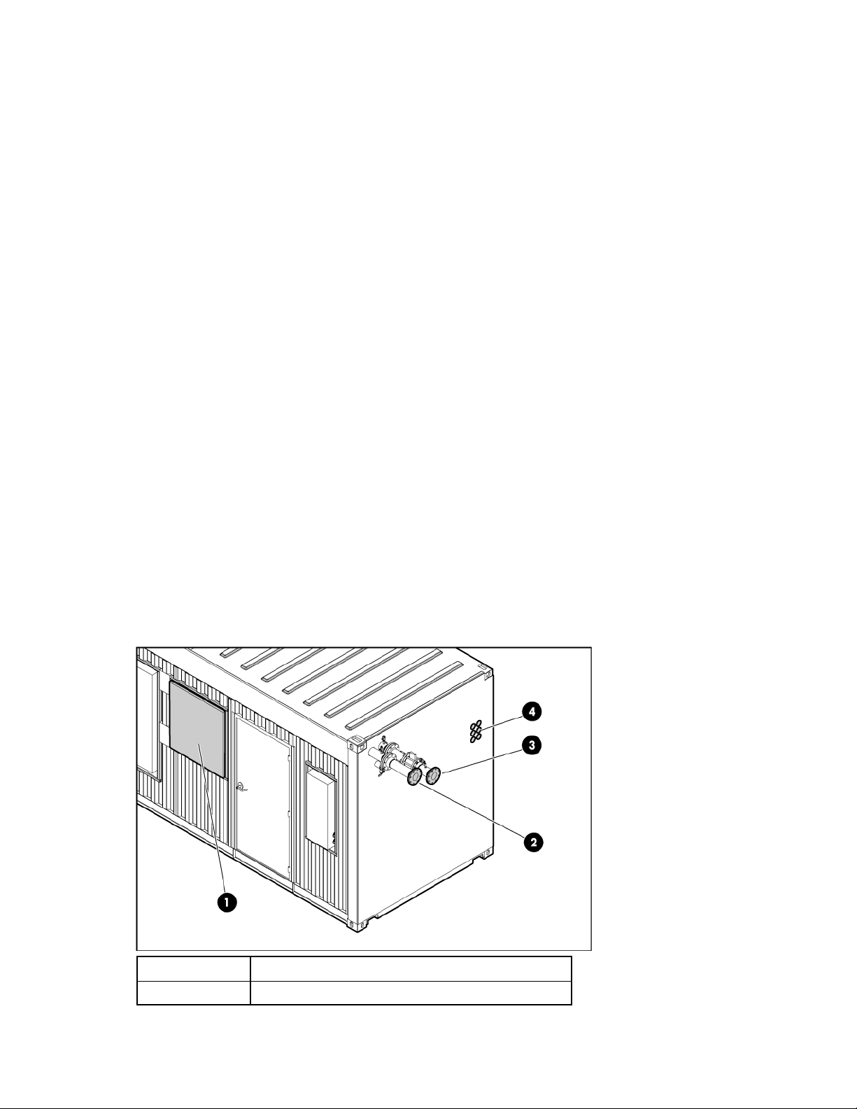
HP POD connection locations
Callout Connection
1 Main input power junction box
Site requirements 7
Page 8

Callout Connection
2 Chilled water return connection
3 Chilled water supply connection
4 IT cable portals∗
∗There are identical IT cable portals on the left side of the HP POD.
Work space requirements
IMPORTANT: Failure to comply with the work space requirements can result in failed
Work platform requirements
The area outside of the HP POD directly in front of the panels must have a work platform. The
specifications of the work platform are:
• The work platform must be a minimum of 1 m (3 ft) wide for standard platforms, and 1.1 m (3.5 ft)
• The work platform surface must be <2.0 m (6.6 ft) from the center of any circuit breaker actuator
Work space lighting
Make sure that the HP POD, transformer, switchboard, and water distribution kit are installed in a well lit
area that complies with local work space lighting requirements, per code regulations.
authorization to power your HP POD by local electrical inspectors.
NOTE: The base of the work platform should be level with the base of the HP POD. If you
choose to leave the HP POD on a trailer, a work platform is required.
wide if the work platform is constructed of grounded metal.
handle.
Environmental considerations
• Install a properly engineered awning to enable access to the building in adverse weather conditions.
• Install lightning protection for the HP POD.
• Make sure that the HP POD is properly grounded.
• Avoid placing the HP POD directly along a drainage path or in an area prone to flooding.
• Raise the HP POD slightly off the ground, or set it on a higher point of elevation. In low elevated
areas, HP recommends setting the HP POD on a concrete housekeeping pad.
• Avoid placing the HP POD directly in the path of external heat loads such as a diesel generator or
Temperature considerations
an air cooled chiller.
The standard operating temperature for the HP POD is from -17.8°C to 54.4°C (0°F to 130°F).
If you choose to purchase the additional insulating paint ("Additional insulation" on page 44), the
operating temperature of the HP POD is from -28.9°C to 54.4°C (-20°F to 130°F).
Site requirements 8
Page 9

Leveling requirements
The site location for the HP POD must be level +/- 0.5 degree tolerance.
Grounding requirements
IMPORTANT: Before installing the HP POD, consult your local AHJ for applicable codes and to
review site-specific location guidelines.
The HP POD must be grounded in accordance to local electric code. HP recommends grounding the HP
POD, the transformer and switchboard, and the water distribution kit to your ground grid system for full
protection.
Lightning protection
If the HP POD is installed in an outdoor environment, HP recommends hiring a lightning protection
consultant to evaluate potential lightning risks and assess possible HP POD lightning protection schemes.
Component documentation
The Operations and Maintenance Manual, that includes all contractor-installed component documentation
and all server and IT equipment documentation is delivered with your HP POD.
Site requirements 9
Page 10

Safety considerations
Safety information
The HP POD has been listed to the UL 69050 as an Information Technology Product and Classified
according to the National Electric Code, NFPA-70, 2008.
The HP POD is not suitable for long term human occupancy.
The HP POD has service access areas for periodic maintenance and service, only to be used by owner
authorized personnel specifically trained in the maintenance and service of the HP POD IT components.
The safety information is specific to the people operating and maintaining the components of the HP POD.
IMPORTANT: All plumbing to and from the HP POD must be completed by a licensed plumber.
IMPORTANT: All wiring in and around the HP POD must be completed by a licensed
electrician.
Operator safety
WARNING: Hearing protection must be worn at all times when working in or around the HP
POD.
WARNING: Any water that drains around the HP POD causes a potential slip hazard. Use
caution where slip hazards are present.
Component health
CAUTION: If the cooling water stops flowing into the HP POD:
• Turn off all IT equipment
• Open the HP POD doors, if weather permits
• View the BMS alarm conditions
CAUTION: Do not put anything inside any of the electrical busways, except the approved
connections to the HP busway dropboxes.
CAUTION: During operation of the HP POD, the overhead fan doors must remain closed.
Safety considerations 10
Page 11

CAUTION: All customer supplied water fittings must be composed of carbon steel, stainless
steel, or copper. Do not use cast iron, aluminum, or PVC fittings.
CAUTION: During operation, avoid leaving the HP POD doors open, to minimize
condensation conditions.
Safety considerations 11
Page 12
Component identification
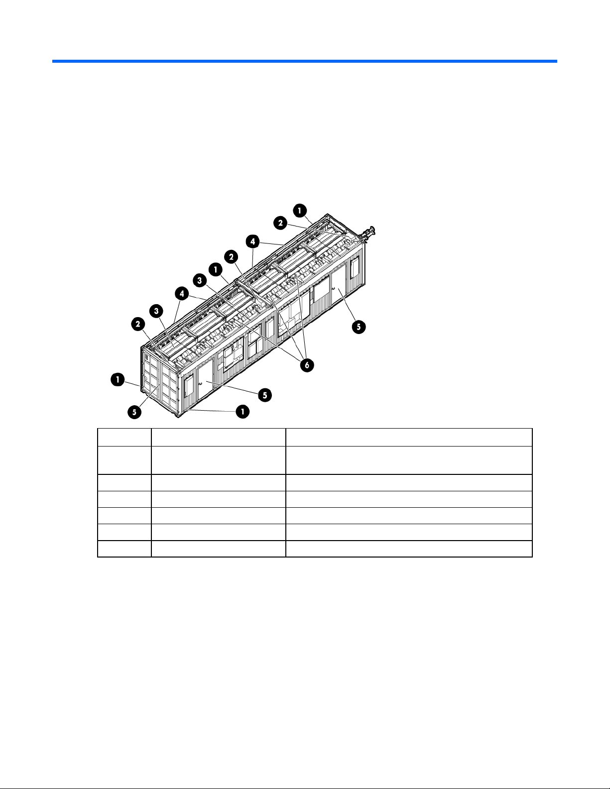
HP POD components
HP POD components
Item Component Description
1 Drain lines Collect water from the drain pans and removes it from the HP
POD
2 Electrical busways Main source of distributing power throughout the HP POD
3 Heat exchangers Use cooling water to cool the air
4 Rear service doors Enable access to the rear of the rack-mounted components
5 Entrance doors Enable access to the front of the rack-mounted components
6 Fan units Circulate the cool air throughout the HP POD
Rack components
There are 22 configured racks inside the HP POD. The following diagram is an example of a fully-loaded
and configured rack. Your rack might include different servers and components.
Component identification 12
Page 13
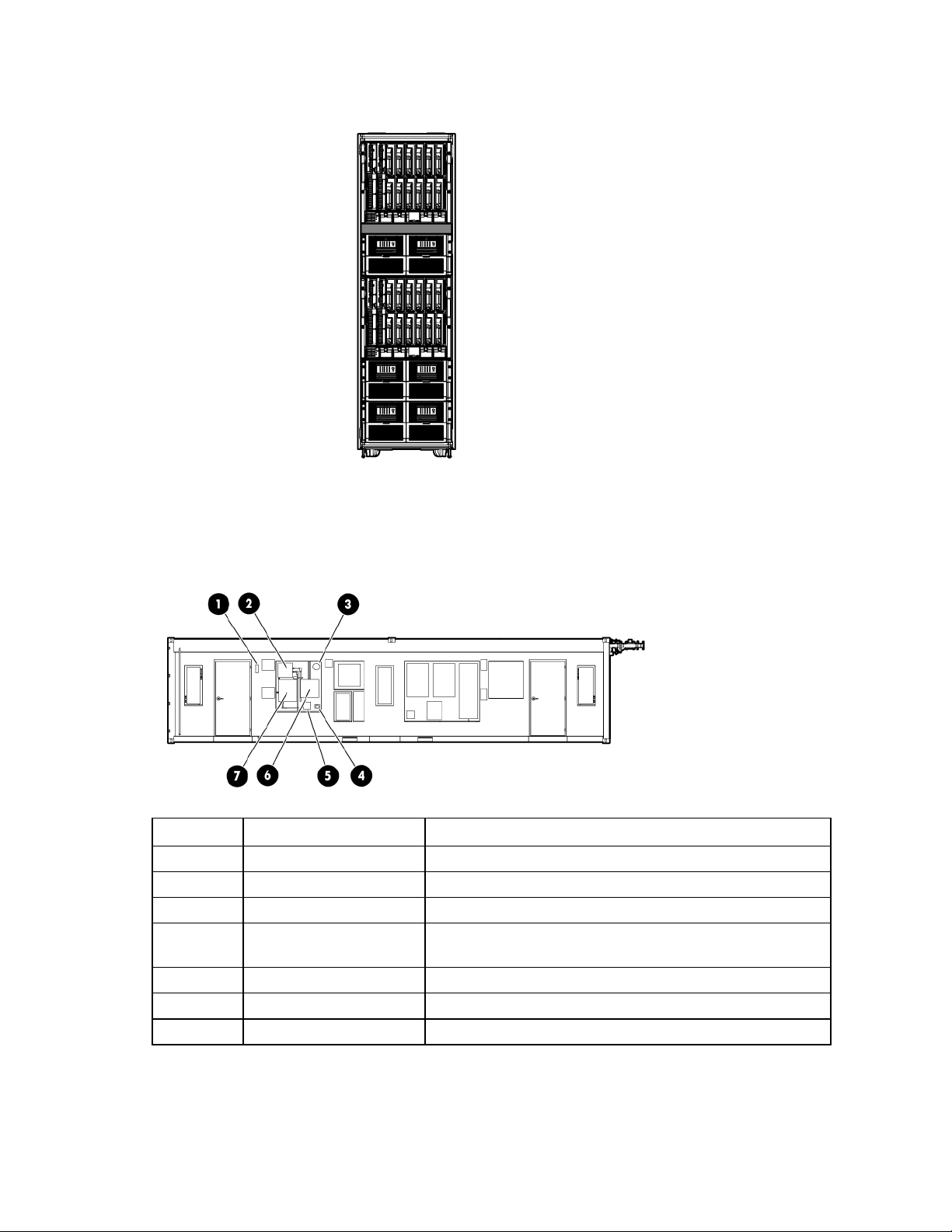
If any of the racks within the HP POD contain empty U space, you must use a heavy duty filler panel to
avoid compromising the integrity of the hot and cold aisle temperatures.
HP POD emergency components
External emergency components
Item Component Description
1 Fire strobe and horn Indication of a fire alarm condition within the HP POD.
2 EPO panel Contains controls and status indicators for the EPO system.
3 EPO alarm lamp (red) Activated when an EPO alarm button is pressed.
4 EPO button Pressing this button cuts off all power to the HP POD and
activates the EPO alarm lamp.
5 Fire alarm XFMR* Fire alarm transformer
6 ASSD panel Samples the air in the HP POD, monitoring smoke
7 Fire alarm control panel Contains controls and status indicators for the fire alarm system.
*Optional component
Component identification 13
Page 14
Internal emergency components
Item Component Description
1 Internal fire strobe and horn
(x2)
2 EPO button (x2) Pressing one of these buttons cuts off all power to the HP POD
3 EPO strobe Activated when an EPO button is pressed.
4 Fire alarm pull switch (x2) Pulling one of these switches activates the fire strobes and
HP POD panel locations
Indication of a fire alarm condition within the HP POD.
and activates the EPO strobe.
horns.
Item Component Description
1 Electrical busway enclosed
circuit breaker (on page 36)
400A enclosed circuit breakers that powers the electrical
busways:
• Two electrical busway panels are activated in the
standard HP POD.
• Three electrical busway panels are activated in the high
density HP POD.
2 EPO panel (on page 36) Contains controls and status indicators for the EPO system
3 Fire alarm panel ("Fire alarm
control panel" on page 38)
Contains controls and status indicators for the fire alarm
system
Component identification 14
Page 15
Item Component Description
4 ASSD panel (on page 36) Air sampling smoke detection system
5 EPO button Cuts off all power to the POD and activates the EPO alarm
lamp.
6 Security panel ("Security panel
location" on page 39)
7 EPMS panel∗ ("EPMS panel"
on page 38)
8 Humidifier ("Humidifier
(optional)" on page 44)*
9 Auxiliary Land power* Provides auxiliary power for the BMS or convenience outlets.
10 BMS panel (on page 36) Building Management System
11 Fan control (FC) panel ("Fan
control panel" on page 38)
12 House panel (on page 38) 120A electrical panel board providing auxiliary HP POD
13 Junction Box Main input box for incoming electrical feeder cables
Reserved for installing interface and power requirements for
any optional security devices installed.
Electrical power monitoring system
Maintains the humidity inside the HP POD within a set range
to minimize static electricity.
120V owner-provided power.
Circuit breakers that control the fan units
electrical requirements
∗Optional component
Transformer and switchboard components (optional)
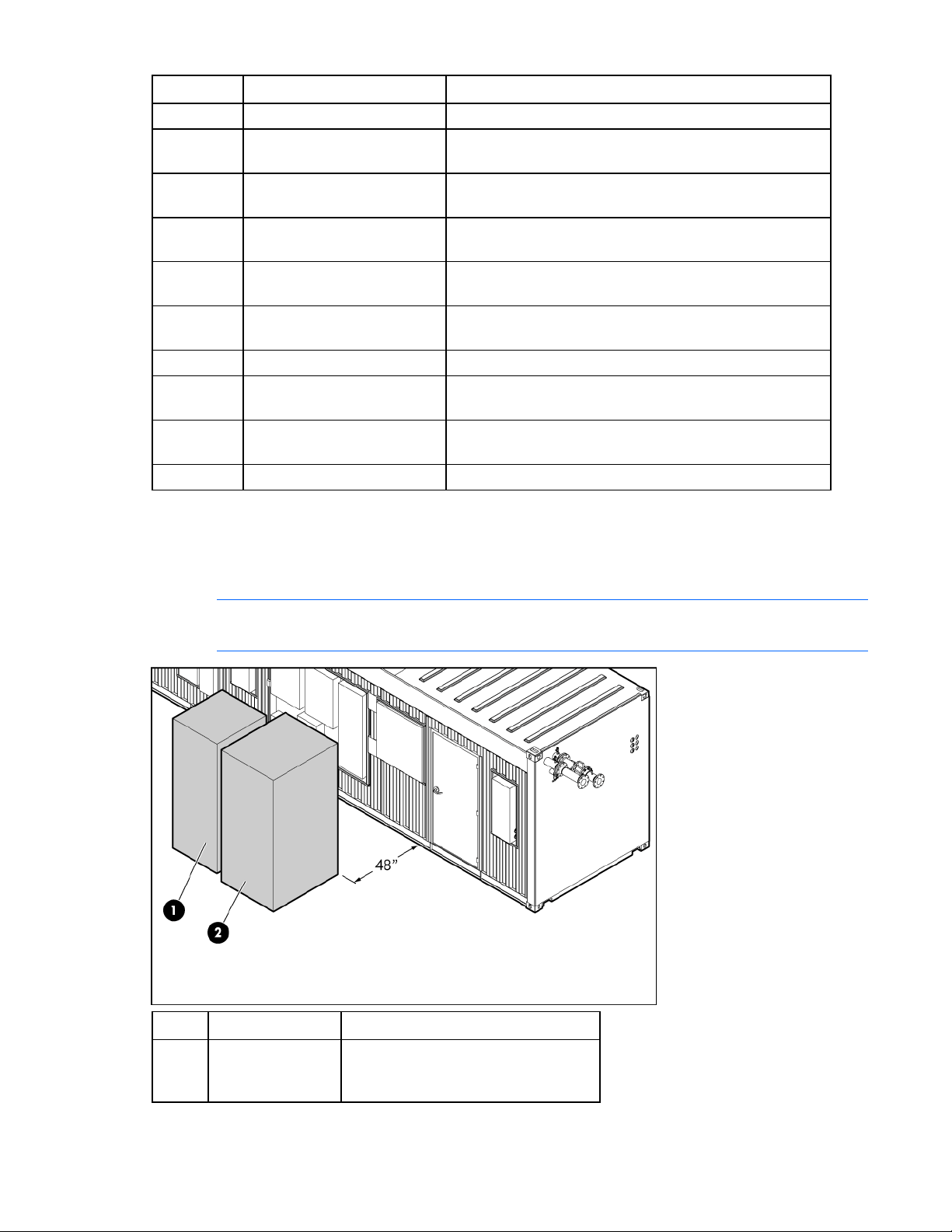
NOTE: The transformer and switchboard must be a minimum of 1.2 m (48 in) away from the
HP POD.
Item Component Description
1 Switchboard Distributes power to each of the
electrical busways breakers and the
House panel
Component identification 15
Page 16
Item Component Description
2 Transformer Transforms power from 480V at your
facility to the 415V needed for the HP
POD
Water distribution kit components (optional)
The water distribution kit is an optional component that is composed of two closed-loop systems: one for
the facility water and one for the HP POD water. The water for the HP POD is supplied through the fill
tank and chemically treated prior to entering the HP POD to ensure adequate water quality.
Item Component Description
1 Facility supply connection Connection to the facility supply line
2 Facility return connection Connection to the facility return line
3 HP POD supply line Connection to the HP POD supply line
4 HP POD return line Connection to the HP POD return line
5 Panel disconnect Power disconnect for water distribution kit
components
6 400A controller board 400A electrical panel board providing auxiliary
electrical requirements
7 Panel disconnect Power disconnect for water distribution kit
components
Component identification 16
Page 17

Installation
HP POD contents
The following items are shipped with the HP POD, and are delivered at the time of your HP POD delivery
and installation.
Standard 40-ft HP POD
Component Quantity Part number
Either of the following:
• HP Transformer and HP Switchboard
• Engineer your own site power for a minimum of 1200A
Either of the following:
• HP Water distribution kit
• Engineer your own site water for a minimum of 240
gal/min
HP 50U rack 22 AN982A
Side panel 50U kit 1 AN991A
50U rack bracket kit 21 AP014A
Either of the following busway dropbox and PDU kits:
• Single phase HP POD busway dropbox kit
• Single phase HP POD PDU bracket kit
-or-
• Three phase HP POD busway dropbox kit
• Three phase HP POD PDU bracket kit
Rack interface seal kit 21 AP013A
Not applicable Not applicable
1
15
44
15
44
AH988A
AP912A
AQ684A
AS613A
AQ683A
High density 40-ft HP POD
Component Quantity Part number
Either of the following:
Not applicable Not applicable
• HP Transformer and HP Switchboard
• Engineer your own site power for a minimum of 1600A
Either of the following:
• HP Water distribution kit
1
AH988A
• Engineer your own site water for a minimum of 240
gal/min
HP 50U rack 22 AN982A
Installation 17
Page 18

Component Quantity Part number
Side panel 50U kit 1 AN991A
50U rack bracket kit 21 AP014A
Either of the following busway dropbox and PDU kits:
• Single phase HP POD busway dropbox kit
• Single phase <sci)short_name> PDU bracket kit
-or-
• Three phase HP POD busway dropbox kit
• Three phase HP POD PDU bracket kit
Rack interface seal kit 21 AP013A
30
88
30
88
AP912A
AQ684A
AS613A
AQ683A
The HP POD is delivered with heavy duty filler panels installed in every empty U space of the racks.
However, HP recommends purchasing additional heavy duty filler panels (AF073A) to prevent
compromising the integrity of the cold aisle set point temperature when IT equipment is removed for
upgrades or maintenance.
The quantity and model of PDUs included with your HP POD are dependent on the IT equipment load they
are supporting.
Preinstallation checklist
CAUTION: Tighten the electrical busway connections after the HP POD is in its final location
Before you begin the installation of your HP POD, verify the following action items have been completed:
• All components are delivered to your facility.
• The HP POD, transformer, switchboard, and water distribution kit are in their final locations.
• You must have facility power at your final location. You can provide the connection cables from the
• You must have facility water at your final location. You can provide the connection hoses from the
• The HP POD has been properly grounded.
Required tools
• 10-ft ladder (2)
• 6-ft ladder (2)
and before you begin the installation process.
facility to the transformer and switchboard or purchase connection cables from HP at additional
costs.
facility to the water distribution kit or purchase connection hoses from HP at additional costs.
• Tongue-and-groove pliers with 4.25-in capacity jaws
• Screwdriver set
• Ratchet set
• Diagonal cutters
• Heavy-duty tie wraps
Installation 18
Page 19
• Pipe wrench
Installing the HP POD using the optional components
The following steps are an overview of the installation procedure for installing a HP POD, using the
transformer, switchboard, and the water distribution kit.
You must obtain service professionals to connect your power and water.
IMPORTANT: All wiring in and around the HP POD must be completed by a licensed
Connecting the water
1. Before you connect your facility water to the water distribution kit, flush the cooling water pipes.
electrician.
IMPORTANT: All plumbing to and from the HP POD must be completed by a licensed plumber.
CAUTION: All customer supplied water fittings must be composed of carbon steel, stainless
steel, or copper. Do not use cast iron, aluminum, or PVC fittings.
a. Connect water directly to the HP POD.
b. Allow the water to run until it is clean, flushing any contaminates that might have entered the
cooling pipes during shipping or delivery.
• NOTE: For quick reference, the water hoses are labeled with green tape and white arrows
pointing in the direction of the water flow.
2. Connect the 4-in return and supply lines from the water distribution kit to the HP POD.
Installation 19
Page 20

3.
Pump domestic or industrial water into the water distribution kit closed-loop system fill tank,
according to the water quality requirements (on page 30).
NOTE: The HP POD pipe design is rated for a maximum pressure rating of 150 psi.
4. Verify that your facility water pressure is within the acceptable range (20-25 psi).
5. Initiate the system pumps on the water distribution kit:
o Manually initiate the system pumps with the main power switch located on the pumps.
- or -
o Connect the water distribution kit to the BMS system, and initiate the system pumps through the
BMS.
Installation 20
Page 21

6.
Open the bleeder valve on the HP POD return line.
7. When the tank is full and there is no more air coming out of the bleeder valve, close the bleeder
valve on the HP POD return line.
8. Verify that your facility water pressure is within the acceptable range (20-25 psi).
• NOTE: For quick reference, the water hoses are labeled with green tape and white arrows
pointing in the direction of the water flow.
Installation 21
Page 22

9.
Connect the facility supply and return lines to the water distribution kit.
10. Connect the water distribution kit to your facility power source.
IMPORTANT: The water supply to the humidifier must be heat-traced to prevent freezing.
Installation 22
Page 23

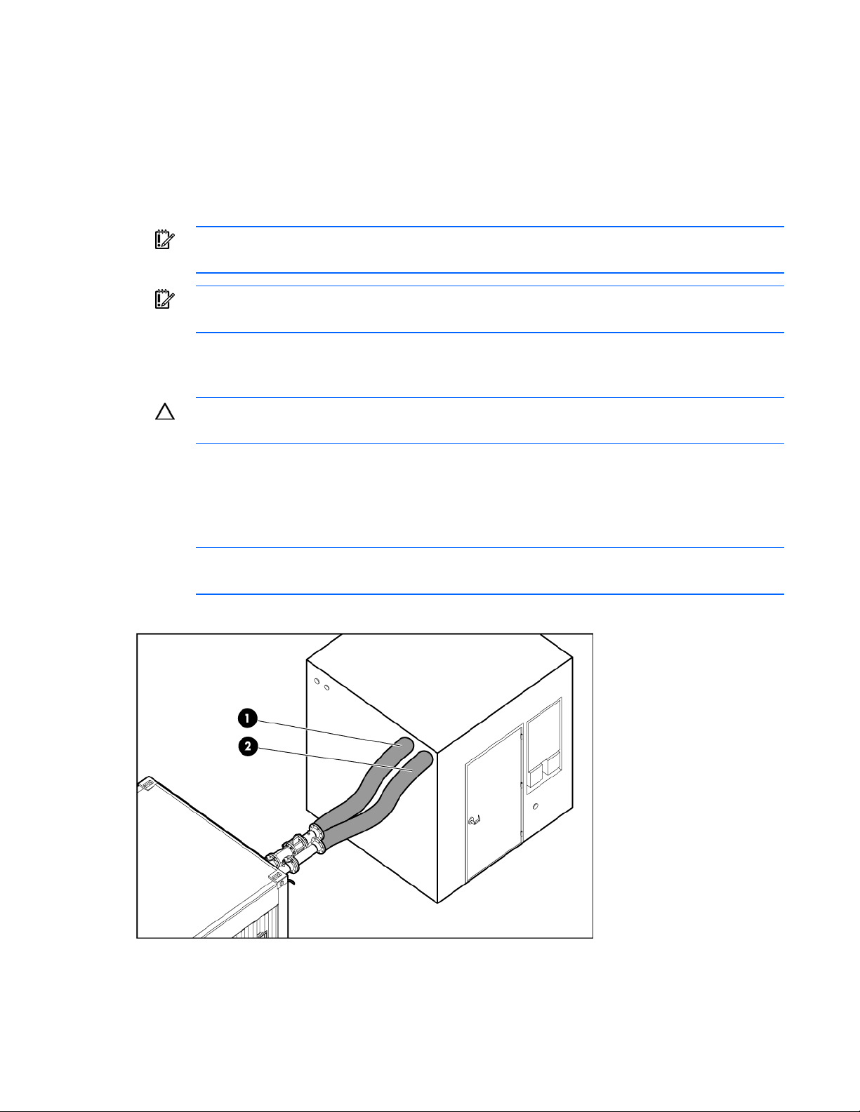
11.
(Optional) Connect the HP POD humidifier to the domestic or industrial water drain (1) and supply
(2) lines. For more information about the humidifier, see the product documentation.
12. Perform one of the following:
o If your HP POD is located inside, HP recommends connecting each of the drains to the local
drain line.
o If your HP POD is located outside, you can choose to connect to the local drain line, or allow the
water to drain off freely in your location. For more information, see Drain locations ("HP POD
drains" on page 28).
Connecting the power
IMPORTANT: A licensed electrician must connect the power according the local electric code,
1. Verify that the HP POD, transformer, and switchboard are in their final locations.
2. Make all connections:
consistent with supplier and consulting engineer drawings.
o Connect the main power leads from your facility to the transformer (1 to 2).
Each connection is labeled with colored tape, according to local standard requirements.
o Connect the transformer to the switchboard (2 to 3).
o Connect the three 3-in flexible conduits from the switchboard to the junction box on the HP POD
(3 to 4).
Installation 23
Page 24

Each connection is labeled. Two of the conduits power the electrical busway breakers and one
powers the house panel.
3. Turn on facility power.
4. Close the three main breakers on the switchboard.
Installation 24
Page 25

5.
Close the main breaker in the House panel on the exterior of the HP POD.
6. Close the remaining breakers in the House panel one by one, following the panel schedule on the
inside of the House panel.
NOTE: If you are installing a high density HP POD, you must also close the main breaker in
the electrical busway 3 panel.
7. Close the main breakers in the electrical busway 1 and electrical busway 2 panels.
8. Inside the HP POD, close the breaker on each drop box that is connected to a rack of IT
components.
9. Power up your remaining racks and IT components following your standard IT startup procedure.
Commissioning the HP POD
Commissioning your HP POD is an optional service and is customized based on your facility. A typical
commissioning process includes the following tests:
• Tighten the electrical busway connections
• Verify accurate electrical installation
• Verify accurate mechanical installation
• Test the operation of the BMS and Cooling controls
• Test the operation of the smoke detection system
• Test the operation of EPO system
Installation 25
Page 26

• Test the operation of the analog and digital phone system
• Verify initial IT start-up
• Conduct an infrared scan of all electrical connections under the start-up IT load
• Verify accurate cooling under start-up IT load
• Provide the HP POD operation owner training
Installation 26
Page 27

Cooling system
HP POD cooling system
CAUTION: Contaminated supply water might cause decreased cooling capacity or disruption
in service. The supply water must meet the guidelines states in the HP Performance-Optimized
Datacenter Site Requirements Information document. Damage caused by contaminated supply
The HP POD has 12 heat exchangers that maintain temperature and cool the equipment installed in the
HP POD. The HP POD heat exchangers receive chilled water from either the water distribution kit or your
facility, cycles the water through the heat exchangers to cool the air, and then the fan units circulate the
cool air throughout the HP POD.
To control the fan speed, you must set a cold aisle temperature through the BMS. A predetermined
differential pressure setpoint between the hot aisle temperature and cold aisle temperature is factory set,
and cannot be altered. The fan units regulate speeds to maintain the cold aisle temperature and
differential pressure between the hot and cold aisle. For more information, see Controlling the fan speed
(on page 27).
Water supply temperature
If you are using a water distribution kit, water is supplied to the HP POD between 13°C and 24°C (55°F
and 75°F). HP recommends that you supply water to the water distribution kit between 4°c and 10°C
(40°F and 50°F).
water is not covered by the warranty.
If you are not using a water distribution kit, HP recommends supplying water to the HP POD between
13°C and 24°C (55°F and 75°F).
Controlling the fan speed
The HP POD fans operate at variable speeds to maintain a predetermined differential pressure setpoint
between the hot aisle and the cold aisle. You set your desired cold aisle temperature through your BMS,
and the fan speed adjusts to maintain the differential pressure setpoint between the hot and cold aisle
temperatures.
You cannot manually adjust the fan speed.
To access the fan units:
1. Unlock the latch for that fan overhead.
Cooling system 27
Page 28

2.
Pull the overhead down.
Condensation management
CAUTION: During operation, avoid leaving the HP POD doors open, to minimize
Supply cooling water that is above the dewpoint inside the HP POD to reduce condensation forming on
the heat exchangers, and also cold enough to maintain the cold aisle temperature setpoint. If both
conditions cannot be met during the HP POD startup, adjust either the cooling water or the cold aisle
temperature setpoint above the dewpoint by one degree every fifteen minutes. During this process, the
coils act as a dehumidifier and establish conditions inside the HP POD for sustained operation. Significant
amounts of condensation might drain from the HP POD during the startup process, if the conditions inside
the HP POD are very warm with high humidity.
During normal operation, some condensation might form on the heat exchangers, and it will be collected
in the heat exchanger drip tray. The drip trays then collect and drain through the condensate drains out of
the HP POD.
HP recommends connecting condensate drains on the HP POD to a facility drain to prevent the collection
of water near the HP POD.
There are three 1.9 cm (¾ inch) condensate drain outlets across the rear of the HP POD directly
connected to the heat exchanger drip trays. The water main external drain is located at the front, left
corner of the HP POD. A fifth drain is located on the (optional) humidifier. For specific drain locations, see
Drain locations ("HP POD drains" on page 28).
condensation conditions.
To avoid excessive buildup of condensate and to conserve energy, consider raising the cooling water
temperature above the dewpoint to manage condensation while maintaining the necessary cooling
capacity.
HP POD drains
Cooling system 28
Page 29

WARNING: Any water that drains around the HP POD causes a potential slip hazard. Use
caution where slip hazards are present.
Water from natural condensation might form. Condensation from the heat exchangers flow to the three
condensate drains across the rear of the HP POD (1). The water main drain catches any water from a
water main leak (2). The humidifier drain removes excess moisture from the air (3).
Item Component
1 Heat exchanger condensate drains
2 Water main supply/return drain
3 Humidifier drain
IMPORTANT: You might have to pipe directly to your local storm or sanitary drain, depending
on local jurisdiction.
If your HP POD is located indoors, you can connect to an external drain line. If your HP POD is located
outdoors, the drained water will simply drip from the HP POD drains out the back of the HP POD.
HP recommends connecting the condensate drains on the HP POD to a facility drain to prevent collection
of water near the HP POD.
Leak detection
If too much water accumulates in a drain tray, an alarm is triggered and sent through the BMS, indicating
that there might be a leak. For more information about alarms, see BMS alarms (on page 41).
Cooling system 29
Page 30

Water quality requirements
Water quality requirements and specifications
• Closed-loop water must not contain any lime scale deposits or loose debris.
• The water must have a low level of hardness, particularly a low level of carbon hardness.
Additionally, the water must not be so soft that it attacks the materials with which it comes into
contact.
• The chilled water temperature to be supplied to the HP POD is 12º to 24ºC (55º to 75ºF). Freezing
water might cause a blockage and damage to the unit. In outside locations subject to freezing
temperatures, an additive such as glycol might be necessary to lower the freezing point. However,
the heat transfer potential of the water is lower, so the equipment must be derated properly.
Acceptable water quality specifications
Water must be maintained per the following acceptable water quality standards.
Parameter Range
pH 8.0–10
Specific conductance at 25ºC
(77ºF)
Alkalinity ("M" as CaCO3) 150–1000 ppm
Sulfur (SO4) 0–150 ppm
Chloride (Cl) 0–100 ppm
Hardness (CaCO3) 0–350 ppm
Calcium hardness (CaCO3) 0–200 ppm
Magnesium hardness (CaCO3) 0–150 ppm
Copper (Cu) < 0.20 ppm
Iron (Fe) < 3.0 ppm
Aluminum (Al) < 0.50 ppm
Sodium (Na) 0–1000 ppm
Silica (SiO2) 0–150 ppm
Zinc (Zn) < 1.0 ppm
Manganese (Mn) < 0.1 ppm
Phosphate Ortho- (PO4) < 3 ppm
Bacteria < 1000 CFU/ml
Suspended solids < 10 ppm
0–2500 µmhos/cm
If your water is out of range, consult a water quality expert.
Water quality requirements 30
Page 31

Frost damage
To avoid frost damage, the water temperature must not be allowed to fall below the minimum permissible
temperature of +4 ºC (+39.2 ºF) at any point in the water cycle.
The water cycle must be drained completely using compressed air before storage or transportation at
freezing temperatures or below.
Plumbing materials to avoid
Do not use the following materials in a closed water system:
• Oxidizing biocides
• Aluminum components
• Brass components with high levels of zinc
• Non-stainless steel Iron components
Water precautions
Take the following precautions before installation of the HP POD:
• Verify that all foreign matter and particulates are flushed from the system.
• Evaluate the short-term and long-term system requirements against the available water capacity.
• Ensure that the chilled water loop is properly designed for liquid cooling systems and is separate
from the sanitary water systems in your building (bathroom, sink, drinking water).
• Ensure facility managers understand the additional load being added to the chilled water supply of
the building. Be aware that the added heat load might affect other components being cooled by the
chilled water plant.
Water temperature
Without a water distribution kit, the temperature of the water supplied to the HP POD must be 12º to 24ºC
(55º to 75ºF). Freezing water might cause a blockage and damage to the unit.
Water quality requirements 31
Page 32

Power management
Electrical busway
The electrical busway is a modular, overhead electrical distribution system that supplies power to the HP
POD IT loads. There are two electrical busways in the standard HP POD (1 and 3) and three electrical
busways in the high density HP POD (1, 2, and 3).
Each PDU is powered by the dropboxes attached to each of the electrical busways.
Disabling power
Power management 32
Page 33

• To disable power to a single PDU, turn off the main switch on that PDU.
• To disable power to a single rack, open the main breaker on the dropbox connected to the electrical
busway.
• To disable power to a single electrical busway, open the appropriate main breaker for that busway
on the corresponding electrical busway panel outside of the HP POD.
Power distribution
The standard HP POD is powered by two electrical busways on the ends of the unit.
Standard HP POD
Feature Specification
Number of busways 2
Frequency 60Hz
Amps (per busway) 400A
Neutral Ampacity (per breaker) 480A
Amps derated percentage 20%
Max usable amps (per busway) 320A
Voltage (per busway) 415V
Grounding Aluminum casing
Phases 3
Power management 33
Page 34

The high density HP POD includes an additional electrical busway in the center of the unit.
High density HP POD
Feature Specification
Number of busways 3
Frequency 60Hz
Amps (per breaker) 400A
Neutral Ampacity (per breaker) 480A
Amps derated percentage 20%
Max usable amps (per busway) 320A
Voltage (per busway) 415V
Grounding Aluminum casing
Phases 3
Rack power
Power is provided to each of the rack by PDUs. The PDUs can be moved around the HP POD to support
component power requirements. The PDUs are powered by the drop boxes attached to each electrical
busway.
For more information regarding power shortages to the PDUs or electrical busway drop boxes, see
Troubleshooting (on page 49).
Power management 34
Page 35

Panels
The following panels are on the exterior of the HP POD.
Item Component Description
1 Electrical busway enclosed
circuit breaker (on page 36)
400A enclosed circuit breakers that powers the electrical
busways:
• Two electrical busway panels are activated in the
standard HP POD.
• Three electrical busway panels are activated in the high
density HP POD.
2 EPO panel (on page 36) Contains controls and status indicators for the EPO system
3 Fire alarm panel ("Fire alarm
control panel" on page 38)
4 ASSD panel (on page 36) Air sampling smoke detection system
5 EPO button Cuts off all power to the POD and activates the EPO alarm
6 Security panel ("Security panel
location" on page 39)
7 EPMS panel∗ ("EPMS panel"
on page 38)
8 Humidifier ("Humidifier
(optional)" on page 44)*
9 Auxiliary Land power* Provides auxiliary power for the BMS or convenience outlets.
10 BMS panel (on page 36) Building Management System
11 Fan control (FC) panel ("Fan
control panel" on page 38)
12 House panel (on page 38) 120A electrical panel board providing auxiliary HP POD
13 Junction Box Main input box for incoming electrical feeder cables
∗Optional component
Contains controls and status indicators for the fire alarm
system
lamp.
Reserved for installing interface and power requirements for
any optional security devices installed.
Electrical power monitoring system
Maintains the humidity inside the HP POD within a set range
to minimize static electricity.
120V owner-provided power.
Circuit breakers that control the fan units
electrical requirements
Power management 35
Page 36

ASSD panel
The ASSD panel draws air from the piping network inside the HP POD and monitors the smoke levels in
the air. If smoke is detected, the ASSD panel automatically sends an alarm to the prewired Fire Alarm
Control Panel.
No user interface settings are required. Interface is established through the Fire Alarm Control Panel.
For more information, see the product documentation included in the Operations & Maintenance Manual
("Component documentation" on page 9).
BMS panel
The BMS panel enables you to connect the HP POD to your building management system. You must bring
an Ethernet cable through the internal passway to connect to the BMS panel.
There is no external user access to the HP POD BMS panel, and all interface settings are controlled
through your facility BMS.
For more information, see Connecting the HP POD to the BMS (on page 40).
Electrical busway enclosed circuit breaker
The electrical busway panels are enclosed circuit breakers that provide power to each of the electrical
busways. For more information, see Electrical busway (on page 32).
EPO Panel
IMPORTANT: If the remote powered 120V branch circuits are operational, they are not turned
The EPO panel contains controls and status lamps for the EPO system, which enables all power in the HP
POD to be turned off except for emergency lighting. Power to the EPO panel is single-phase 240V AC,
provided by the house panel.
Two EPO alarm buttons for directly shutting off non-emergency HP POD power are located inside the HP
POD, and one EPO alarm button is located on the outside of the HP POD.
To check that the EPO alarm buttons and alarms are functional, switch to Test mode and then press an
EPO alarm button. This procedure activates the EPO alarms without cutting off power to the HP POD.
off during an EPO shutdown.
Power management 36
Page 37

To enable remote access to the EPO system, switch to Bypass mode.
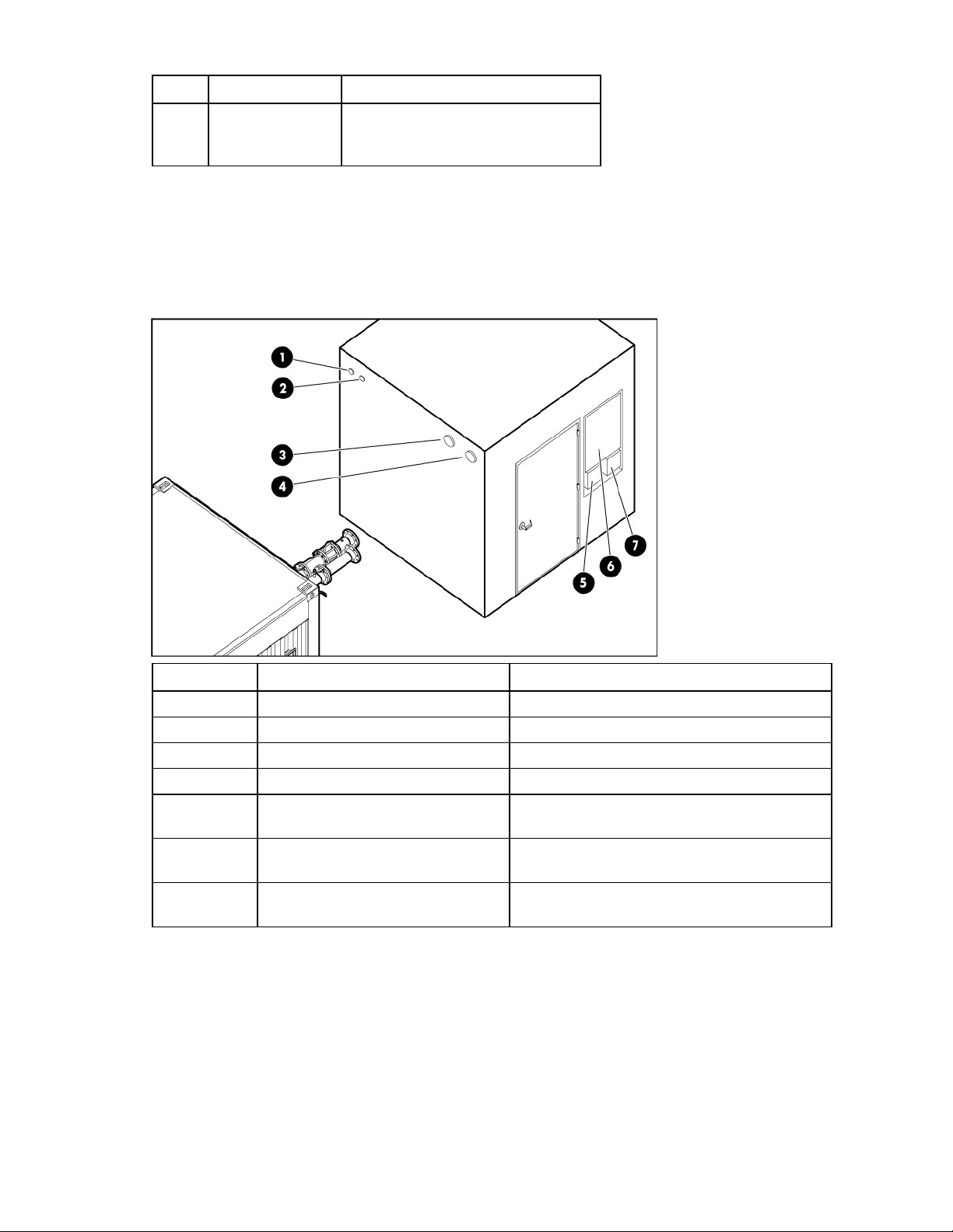
Callout Component Description
1 Power On LED Indicates the EPO is functional, and
operating in Test mode, Armed mode,
or Bypass mode.
2 EPO Armed mode LED Indicates the EPO is operating in
Armed mode.
3 Reset button Resets the EPO system after an EPO
alarm has been triggered.
4 Three way key-operated
switch
5 System alarm/ EPO
shutdown
(red)
6 System Test mode LED
(amber)
7 EPO Bypass mode LED
Sets the EPO operating mode (Test,
Armed, or Bypass).
Indicates an EPO alarm has been
triggered and non-emergency HP POD
power has been shut off.
Indicates the EPO is undergoing a
system test.
Indicates the EPO is in Bypass mode.
(green)
After an EPO alarm, reset the EPO system:
1. Use the button key release mechanism to restore the EPO alarm buttons to their normal state.
2. Reset the main breaker in the House panel.
3. Reset the electrical busway breakers.
4. Press the Reset button on the EPO panel.
EPO modes
The EPO panel operates in three modes: Armed, Test, and Bypass. The operating mode is determined by
the status of a key-operated selector switch on the EPO panel. The switch status can be reported to a
monitoring system that is external to the POD.
Power management 37
Page 38

Armed mode—Pressing a red EPO button on the POD causes the following events:
• The red System Alarm/EPO Shutdown light on the EPO panel illuminates to indicate that an EPO
switch has been activated. (This light remains illuminated until all EPO buttons are restored to their
normal state by means of a key release mechanism, and the Reset button on the EPO panel is
pressed.)
• The EPO activated relay is energized and sends a signal to the EPO panel to energize the
associated control relays.
• The control relays within the EPO panel shut down the affected circuit breakers in the POD.
Test mode—All associated EPO functions are disabled, and the amber System Test Mode light on the EPO
panel is illuminated. This mode enables the EPO buttons to be tested without removing power to the POD.
When an EPO button is pressed, the EPO Activated relay is energized, and it energizes the associated
control relays in the EPO panel. Although the EPO functions are disabled, the horn and strobe alarm are
activated. To silence the alarm, press the Reset button on the EPO panel.
Bypass mode—All EPO functions and test functions are disabled. When the EPO panel is operating in this
mode, the green EPO Bypass light on the EPO panel is illuminated.
EPMS panel
The electric power managing system (EPMS) is composed of 120V, Nema 515R rated auxiliary power.
The panel optionally provides additional power for auxiliary components, mainly the BMS.
• If you connect land power to this panel, the BMS is powered by external land power.
• If you do not connect land power to this panel, the BMS is powered by the House panel.
Fan control panel
The Fan Control panel houses the relay system that controls the fan speeds within the HP POD, based on
maintaining the cold aisle temperature set through the BMS.
You do not have to access to the Fan Control panel, and no interface setting is required.
Fire alarm control panel
If you connect your central fire alarm system to the fire alarm control panel, any emergency alarm can be
sent directly over your facility alarm system.
For more information about the fire alarm control panel, see the product documentation included in the
Operations & Maintenance Guide.
House panel
The House panel is a 120A panel board that provides power and electrical requirements to all auxiliary
HP POD components.
If a breaker is tripped open, you can access to the outside of the House panel and reset the breakers. You
can also reset the HP POD components after an EPO alarm. If one or more breakers continually trip,
contact HP ("HP contact information" on page 55).
The standard panel schedule resides inside the panel breaker box and can be referenced when
necessary.
Power management 38
Page 39

Security panel location
If you decide you want to install a security panel, the HP POD has a predesignated location for a security
panel.
Power management 39
Page 40

Building management system
Using a building management system (BMS)
NOTE: If your site does not have a BMS, then BMS data can be sent and viewed to a set IP
address, communicating via Ethernet cable connected to the internal passway of the BMS
HP recommends connecting the HP POD to your facility building management system (BMS),
communicating through Ethernet cable connected to the internal passway of the BMS Panel. For more
information, see Connecting the HP POD to the BMS (on page 40).
The standard BMS protocol, BACnet, is a data communication protocol for building automation and
control networks.
A BMS offers:
• A supported communication interface that can monitor and control HP POD components remotely
• Immediate notification of all alarm messages
• Ability to manage and configure utility devices
By connecting your HP POD to a BMS system, you can monitor:
• Cold and hot aisle temperatures
• Supply and return water temperatures
• Cooling water flow rate entering the HP POD
Panel.
• Cooling tonnage
• Smoke alarms
• EPO alarms
For additional points that can be monitored, see the I/O (Input/Output) Controls Points List in the
Operations and Maintenance Manual ("Component documentation" on page 9).
Connecting the HP POD to the BMS
1. Install and configure the operating system (Microsoft® Windows® or Linux) on a designated
management server.
2. Install the management software on the management server.
3. Connect the management servers to the building network.
4. Insert your BMS Ethernet cable through the IT portals on the left end of the HP POD.
5. Plug the Ethernet cable into the designated BMS jack on the interior of the HP POD.
Building management system 40
Page 41

For more information, see the junction control system documentation included in the Operations &
Maintenance Manual ("Component documentation" on page 9).
Managing BMS settings from the HP POD
The BMS controls can be accessed from a laptop if necessary. To access the BMS using a laptop at the
HP POD, connect an Ethernet cable between a laptop and the designated BMS jack on the interior of the
HP POD.
BMS alarms
The alarms pertaining to the health of the HP POD and its components are relayed through the BMS.
Building management system 41
Page 42

Alarm Meaning Solution
Fan failure One of the fans is not working. If you are still within your service
contract, contact HP service.
Sensor failure One of the sensors is not working. If you are still within your service
contract, contact HP service.
Leak detection The drain tray senses water. Turn off the water flowing into your HP
POD at the facility line. Turn off all IT
components, so that the components do
not overheat. If you are still within your
service contract, contact HP service.
Change filter* The return air filters are full. Replace the return air filters.
High temperature The cold aisle temperature has
surpassed the set point temperature.
Low temperature The cold aisle temperature is too low. Check you HP POD components to
EPO Someone has activated the EPO
system and shut down the HP POD.
*The change filter alarm is only relayed to your BMS if you have the optional filter replacement sensor installed.
Check to make sure that you have
water flowing into your HP POD and
that the fans are blowing. If you are still
within your service contract, contact HP
service.
make sure all components are
operating as normal. If you are still
within your service contract, contact HP
service.
Follow emergency procedures.
After the emergency is cleared, reset
the EPO and other HP POD systems.
Safety and security alarms
Alarms pertaining to the safety of the HP POD are (optionally) relayed through your building fire and
security dispatch.
Alarm Meaning Solution
Fire alarm* A fire has been detected in the HP
POD.
Security alarm
(optional)
EPO Someone has activated the EPO
*The fire alarm is only relayed to your building fire and security dispatch if you have connected your facility to the
fire alarm panel.
Fire alarm sequence of operations
If a fire alarm or manual pull station is activated, the HP POD follows this sequence of operations.
1. The HP POD sends an alarm signal to the building fire and security dispatch.
2. The AC unit shuts down.
3. The HP POD security lights flash and the horns sound the 30-second evacuation alarm.
There has been a security breach. Follow emergency procedures for your facility.
system and shut down the HP POD.
Activate the EPO. Follow emergency
procedures for your facility.
Follow emergency procedures for your facility.
Building management system 42
Page 43

4.
After a 30-second delay, the HP POD releases the suppressant gas, if the optional fire suppressant
system is installed.
Building management system 43
Page 44

Optional components
Additional insulation
You can choose to have additional insulated paint added to your HP POD prior to shipment. The
Air filter sensor
additional insulation will enable the HP POD to function properly in temperatures as low as -29°C (-20°F).
The air filter sensor is an optional component that, if installed, alerts you to change your air filters. The
sensors are located near each of the 12 air filters. If the air filters are full and should be replaced, an alert
will be sent via your BMS.
Humidifier (optional)
If you choose to connect to the humidifier, it maintains the humidity within the HP POD within a set range,
according to ASHRAE standards.
Maintaining the humidity helps to minimize static electricity within the HP POD.
For more information about the humidifier, see the product documentation included in the Operations &
Maintenance Manual ("Component documentation" on page 9).
Fire protection system
The fire protection system is a HP POD self-contained system, with no connection to your BMS. The fire
protection system consists of 12/30 pre-em novac, a clean agent fire suppressant, eliminating the need
for additional water to be connected to the HP POD in case of a fire emergency.
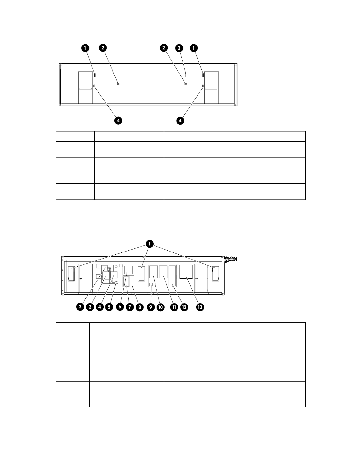
HP POD security
Routing raceways for the following security options are provided by HP and can be installed as a custom
service option. You are responsible for providing additional hardware, cabling, and controllers to support
these options.
Security options:
• Key lock hardware—Standard security provided
• Card reader security—Junction boxes provided at every entrance to upgrade security, if desired.
• Magnetic or electronic locks—Prewiring provided at every entrance to upgrade security, if desired.
Magnetic or electronic locks are not provided.
• Internal/external cameras—Camera mounting locations are provided along with empty conduit and
pull drag lines.
Optional components 44
Page 45

Each external panel is secured through key lock hardware.
The following locations have been prewired for your own security upgrades.
Callout Description
1 Prewired junction box locations
2 Card reader locations
3 Internal camera locations
4 External camera locations
Transformers and switchboards
HP offers several transformers and switchboards to supply your power needs.
On-site connections include:
• From your main facility power to the primary side of the transformer
• From the transformer to the switchboard
• From the feeder breaker lugs within the switchboard assembly to the HP POD
The standard cables should allow for placing the transformer and switchboard approximately 3.0 m (10
ft) away from the HP POD. Installation costs assume that connections are within the 3.0 m (10 ft)
recommendation. If you place the transformer and switchboard more than 3.0 m (10 ft) away from the HP
POD, additional planning and costs are involved.
Water distribution kit
HP recommends using the optional water distribution kit to provide water to your HP POD. For more
information about the kit, see Water distribution kit components ("Water distribution kit components
(optional)" on page 16).
NOTE: The water distribution kit pipes are flushed prior to shipment.
The water distribution kit is enclosed within a 10 ft ISO container that includes internal lighting and
heating. The heater comes equipped with a programmable thermostat that you can set to run as needed
to ensure the water temperature inside does not drop below freezing.
Optional components 45
Page 46

Water distribution kit power requirements
Callout Specification
1 30 AT, 30 AF, 3P
2 Within facility 480V, 3 phase power distribution equipment
3 (3)#10, (1)#10G, 1"C. Feeder sized on a maximum run of
100 ft
4 Motor controller at skid
5 30 AT, 30 AF, 3P
6 20 AT, 3P
7 15 AT, 3P
8 (3)#12, (1)#12G ¾"C
9 P–1
10 P–2
11 UH–1
Optional components 46
Page 47

Frequently asked questions
HP POD frequently asked questions
Question Answer
Can I keep the HP POD on the trailer? Yes, if you choose to lease the trailer from HP or if your
purchase your own trailer and have the HP POD installed on
your trailer prior to shipment. You must also:
• Ensure that the site is stable and has been prepared
correctly for the additional weight of the trailer.
• Provide a work platform to access exterior panels.
What cooling capacity ranges are available
in the HP POD?
What electrical power capacity ranges are
available in the HP POD?
Can the level of heat removal be regulated
in proportion to the waste heat generated?
How is water connected to the HP POD? There are two options to connect water:
Does the HP POD require maintenance? Yes, general maintenance is outlined in this document. Contact
Does condensation form? During normal operation some condensation might form, but the
How does the HP POD control humidity? The relative humidity is maintained between 30–70%.
Does the air flow within the HP POD
produce static electricity?
The HP POD is capable of cooling rack-mounted components
consuming up to 605 kW of electrical power.
The low density HP POD is capable of powering components up
to 450 kW of electrical power.
The high density HP POD is capable of powering components
up to 605 kW of electrical power.
Yes, the control system automatically adjusts the air flow to
remove heat generated in the HP POD.
• You directly connect your facility water to the HP POD,
making sure the water meets the water requirements
("Water quality requirements" on page 30) for quality,
temperature, and flow rate.
• You connect your facility water to the water distribution kit,
which is then connected to the HP POD through two 4-in
150-psi hoses.
HP service for additional information.
condensation does not reach any rack-mounted components or
cause any damage. Excess condensation from the heat
exchangers is collected and drained via three condensate
drains ("HP POD drains" on page 28) across the rear of the HP
POD. In most cases, the condensation evaporates prior to
reaching the condensate drains.
If additional humidity is required, connect your facility water to
the humidifier supply on the front of the HP POD.
The humidity of the HP POD is maintained between 30–70% to
ensure that dangerous levels of static electricity cannot build.
Frequently asked questions 47
Page 48

Question Answer
Is the HP POD weather resistant? If there is an external leak, the HP POD is weatherproof and
has sufficient protection against the encroachment of water
inside the HP POD.
What happens if there is an internal leak? If there is an internal leak, the water collects in the condensation
drain pans or the water main drain pan. The additional water
present in the condensation drain pan triggers a Leak Detection
alarm, sent over the BMS.
What will happen if water stops flowing to
the HP POD?
The building BMS receives a High Temperature alarm. An EPO
will occur automatically if the hot aisle temperature exceeds
66°C (150ºF).
HP recommends shutting down all IT components or pressing
any EPO button to manually power down the servers, to
maintain server health, until the root problem can be solved.
At what smoke level will an alarm be
issued?
You can set the four different ranges at which the ASSD panel
smoke detector issues an alarm. For more information, see the
smoke detector manual supplied with the HP POD.
Can I switch out my servers and other rackmounted components?
The HP POD supports any IT equipment that uses front to rear
air flow cooling to maintain thermal integrity.
If you must remove a server or other rack-mounted component
for any prolonged period, you must replace it with a similar
component or a heavy-duty blanking panel so that the HP POD
interior can maintain thermal integrity.
How will I be notified if there is an
emergency in the HP POD?
The smoke alarm automatically detects incipient fires and
activates several different types of fire alarms:
• Visible—Internal and external HP POD strobes
• Audible—Horn
• Remote notification through the building fire alarm control
panel (optional)
Water emergencies are detected through the fire alarm control
panel and drain trays, an alarm is initiated, and the building
BMS is notified.
If the fans are not functioning correctly, an alarm is initiated
and the building BMS is notified.
Frequently asked questions 48
Page 49

Troubleshooting
HP POD troubleshooting
Issue Resolution
The water is not flowing, or flowing too
slowly.
The HP POD is overheating. If the fan is not functioning, check the integrity of the electrical
The strobe lights are flashing. Either the EPO or the fire alarm system has been activated. Get
There is a leak inside the HP POD. Locate and note the source of the leak. Prevent the leaking
There is no power to one rack. 1 Verify that the racks on either side of the rack have power.
There is no power to multiple racks. 1 Verify that the HP POD is receiving power.
There is no power to the HP POD. Check the status of the connection transformer and switchboard.
Verify that all applicable valves are open. Inspect the water
lines for blockage, unblock, or replace them as necessary.
connection to the fan. If the electrical connection seems OK,
replace the fan.
If the fan is functioning, check for a kink or blockage in the
water line to the heat exchanger.
Contact HP service.
out of the HP POD immediately and follow standard emergency
procedures for your facility.
water from contacting any electrical equipment. Repair the leak
as soon as possible.
2 Check the status of the busway dropbox for that rack.
• If a breaker has tripped, reset the breaker box and verify
• If none of the busway dropbox breakers has tripped, check
• If none of the breakers on the busway dropbox or PDUs
2 Check the status of each of the electrical busway panels. If
3 Check the status of the connection transformer and
If one of the breakers has tripped, reset the breaker and verify
that power has been restored to the HP POD.
that power has been restored to the rack.
the status of the PDUs for the rack. If the input or output
breakers have tripped, reset the PDU and verify that power
has been restored to the rack.
have tripped, replace the busway dropbox.
one of the breakers has tripped, reset the breaker and verify
that power has been restored to the racks.
switchboard. If one of the breakers has tripped, reset the
breaker and verify that power has been restored to the
racks.
Troubleshooting 49
Page 50

Specifications
HP POD specifications
Features Specifications
Dimensions 40 ft x 8 ft x 9.5 ft
Maximum weight 30,000 lb (empty)- 101,000 lb (fully-loaded)
Maximum power/ cooling
Maximum rack quantity 22 racks
Rack Units (RU) per rack 50 RU
Rack Units (RU) maximum 1100 RU
Nominal power/ cooling per rack 25 kW
Maximum power/ cooling per rack 35 kW
Power input voltage 415 VAC, 3 Phase, 50/60 Hz, with neutral
Power distributed internally Through 2 400A electrical busways
Customer access Double-door on one end
Network supported Bulk cable pass-through-fiber
• 450 kW (Standard POD)
• 605 kW (High density POD)
240/415 VAC, 50/60 Hz
Two 3 ft x 7 ft doors to the cold aisle (customer access)
Four 6 ft x 7 ft doors to the hot aisle (rear component access)
Bulk cable pass-through-copper
(Optional) External rated DEMARC box
Electrical specifications
Panel information
Feature Electrical busway panel House panel
Number of panels
Amps (per panel) 400A 225A
Poles (per panel) 1 30–42
Phases 3 3
Circuit breaker information (Input)
• 2 (Standard HP POD)
• 3 (High density HP POD)
1
Specifications 50
Page 51

Feature Specification
Number of input circuit breakers 2: 1 per panel
Protection percentage 80%
Amps (per breaker) 400A
Fire alarm panel connections
The electrical layout of the fire alarm system is as described in the schematic drawing supplied with the
HP POD.
Water specifications
Water supply specifications without a water distribution kit
Feature Specification
Facility input temperature to HP POD 12º to 24ºC (55º to 75ºF)
Operating pressure 137,895 to 172,369 Pa (20 to
Rated pressure max 1,034,213 Pa (150 psi)
HP POD pressure drop 110,316 Pa (16 psi)
HP POD water flow rate 908.5 l/min (240 gal/min)
Cooling water supply and return
connections
Humidifier 3.79 l/hr (1 gal/hr) domestic
25 psi)
(2) 10.16 cm (4 inch) 150#
flange
water from an alternate supply
source
Water supply specifications with a water distribution kit
Feature Specification
Facility input temperature to the water
distribution kit
Water distribution kit temperature output to
the HP POD
Operating pressure 137,895 to 172,369 Pa (20
Rated pressure max 1,034,213 Pa (150 psi)
HP POD pressure drop 110,316 Pa (16 psi)
Water distribution kit pressure drop 34,474 Pa (5 psi) max
Water flow rate to the water distribution kit 757 to 1,893 l/min (200 to
Water distribution kit flow rate to the HP POD 908.5 l/min (240 gal/min)
Cooling water supply and return connections (2) 10.16 cm (4 inch) 150#
4º to 10ºC (40º to 50ºF)
12º to 24ºC (55º to 75ºF)
to 25 psi)
500 gal/min) based on a
facility operating delta T
range of 6°to 12°C (10º–
20ºF)
flange
Specifications 51
Page 52

Feature Specification
Humidifier 3.79 l/hr (1 gal/hr) domestic
Rack specifications
Standard HP POD racks (AN982A)
Feature Specification
U height 50U
Width 56-mm
Depth 1,000-mm
Maximum load weight 3,000 lb
International shock-mounted HP POD racks (AT052A)
Feature Specification
U height 46U
Width 56-mm
Depth 1,000-mm
Maximum load weight 2,760 lb
water from an alternate supply
source
Thermal and air flow performance
Maximum thermal and air flow
performance parameters
Air temperature—Inlet to rackmounted components
Chilled water temperature 12°–19°C (55°–65°F)
Total rack-mounted component air
flow
Chilled water flow rate
Chilled water pressure differential at
flow needed to meet thermal
specifications
Server heat load
HP POD specification
Cold aisle setpoint temperature in BMS
Variable as required to maintain cold
aisle setpoint temperature
• 240 gal/min (908 l/min) without
utility module
• 280 gal/min (1,060 l/min) with
utility module
5 psi max
• 450 kW standard HP POD
• 605 kW high density HP POD
Specifications 52
Page 53

Environmental specifications
Features Specifications
Operating temperature -18ºC to 54ºC (0ºF to 130ºF)
Non-operating
temperature*
Transit temperature** -30ºC to 60ºC (-22ºF to 140ºF), up to 72 hours
Operating humidity
2ºC to 54ºC (35ºF to 130ºF)
• 15% to 80% relative noncondensing
• 26ºC (79ºF) maximum wet bulb temperature
Non-operating humidity*
• 5 to 95% relative noncondensing
• 39ºC (102ºF) maximum wet bulb temperature
Operating altitude -76.2 to 3,048 m (-250 to 10,000 ft)
Non-operating altitude -76.2 to 9,144 m (-250 to 30,000 ft)
*For non-operating specifications, consider the temperature of computer and IT equipment inside the HP POD.
**The HP POD must be drained before it is moved to a new location.
For areas prone to freezing, consult HP for applicable operating solutions and evaluate water lines as described in
the Frost damage (on page 31) section of this document.
Water distribution kit specifications
Feature Specification
Dimensions 10 ft x 8 ft x 9 ft
Tank capacity 7.8 gal
Pumps electrical 480V, 3-phase, 60 Hz
Pumps flow 240 gal/min
Chemical pot feeder
capacity
10 gal
For more information, see Water specifications (on page 51).
Specifications 53
Page 54

Maintenance
Periodic maintenance
Perform periodic inspections of the POD to ensure there is no sign of overheating. During periodic
Electrical busway maintenance
inspections, pay special attention to electrical connections and wiring.
Periodically tighten the electrical busway connections. HP recommends tightening the electrical busway
connections every six months.
Inspect the busway drop boxes for loose connections, and tighten if necessary.
Water system maintenance
HP does not maintain your water system quality.
Consult a water treatment specialist to perform the following maintenance:
Flush the HP POD
How often you must flush the HP POD depends on how often you shutdown the HP POD and the water
quality.
Maintain water quality
The water treatment specialist should periodically take a water sample and add new chemical treatments
to the HP POD water or water distribution kit as needed to maintain the specified water quality ("Water
quality requirements" on page 30).
Air filter replacement
There are twelve 14 in x 36 in x 1 in air filters inside the HP POD.
If you have the optional air filter sensor (on page 44) installed, you will be notified through your BMS
when you need to change a filter.
If you do not have the sensor installed, HP recommends periodically inspecting and changing each air
filter.
Air and water heat exchanger maintenance
The air and water heat exchanger requires no maintenance. If particulates are present in the cooling
water, a filter must be fitted immediately upstream from the water inlet fittings. Check the functionality of
the condensation drainage system regularly. Regularly perform visual inspections for leaks (annually).
Maintenance 54
Page 55

Before you contact HP
Be sure to have the following information available before you call HP:
• Technical support registration number (if applicable)
• Product serial number
• Product model name and number
• Product identification number
• Applicable error messages
• Add-on boards or hardware
• Third-party hardware or software
• Operating system type and revision level
HP contact information
For the name of the nearest HP authorized reseller:
• See the Contact HP worldwide (in English) webpage
(http://welcome.hp.com/country/us/en/wwcontact.html
For HP technical support:
• In the United States, for contact options see the Contact HP United States webpage
(http://welcome.hp.com/country/us/en/contact_us.html
o Call 1-800-HP-INVENT (1-800-474-6836). This service is available 24 hours a day, 7 days a
week. For continuous quality improvement, calls may be recorded or monitored.
o If you have purchased a Care Pack (service upgrade), call 1-800-633-3600. For more
information about Care Packs, refer to the HP website (http://www.hp.com/hps
• In other locations, see the Contact HP worldwide (in English) webpage
(http://welcome.hp.com/country/us/en/wwcontact.html
).
). To contact HP by phone:
).
).
Maintenance 55
Page 56

Regulatory compliance notices
Regulatory compliance identification numbers
For the purpose of regulatory compliance certifications and identification, this product has been assigned
a unique regulatory model number. The regulatory model number can be found on the product nameplate
label, along with all required approval markings and information. When requesting compliance
information for this product, always refer to this regulatory model number. The regulatory model number is
Federal Communications Commission notice
not the marketing name or model number of the product.
This equipment has been tested and found to comply with the limits for a Class A digital device, pursuant
to Part 15 of the FCC Rules. These limits are designed to provide reasonable protection against harmful
interference when the equipment is operated in a commercial environment. This equipment generates,
uses, and can radiate radio frequency energy and, if not installed and used in accordance with the
instructions, may cause harmful interference to radio communications. Operation of this equipment in a
residential area is likely to cause harmful interference, in which case the user will be required to correct
the interference at personal expense.
Modifications
The FCC requires the user to be notified that any changes or modifications made to this device that are
not expressly approved by Hewlett-Packard Company may void the user’s authority to operate the
equipment.
Cables
Connections to this device must be made with shielded cables with metallic RFI/EMI connector hoods in
order to maintain compliance with FCC Rules and Regulations.
Canadian notice
This Class A digital apparatus meets all requirements of the Canadian Interference-Causing Equipment
Regulations.
Cet appareil numérique de la classe A respecte toutes les exigences du Règlement sur le matériel
brouilleur du Canada.
European Union regulatory notice
This product complies with the following EU Directives:
Regulatory compliance notices 56
Page 57

• Low Voltage Directive 2006/95/EC
• EMC Directive 2004/108/EC
• Machinery Directive 98/37/EEC
Compliance with these directives implies conformity to applicable harmonized European standards
(European Norms) which are listed on the EU Declaration of Conformity issued by Hewlett-Packard for this
product or product family.
This compliance is indicated by the following conformity marking placed on the product:
This marking is valid for non-Telecom products and EU harmonized Telecom products (e.g. Bluetooth).
This marking is valid for EU non-harmonized Telecom products.
*Notified body number (used only if applicable—refer to the product label)
Hewlett-Packard GmbH, HQ-TRE, Herrenberger Strasse 140, 71034 Boeblingen, Germany
Disposal of waste equipment by users in private households in the European Union
This symbol on the product or on its packaging indicates that this product must not be disposed
of with your other household waste. Instead, it is your responsibility to dispose of your waste
equipment by handing it over to a designated collection point for the recycling of waste
electrical and electronic equipment. The separate collection and recycling of your waste
equipment at the time of disposal will help to conserve natural resources and ensure that it is
recycled in a manner that protects human health and the environment. For more information
about where you can drop off your waste equipment for recycling, please contact your local
city office, your household waste disposal service or the shop where you purchased the
product.
BSMI notice
Regulatory compliance notices 57
Page 58

Chinese notice
Class A equipment
Korean class A notice
Japanese class A notice
Regulatory compliance notices 58
Page 59

Acronyms and abbreviations
AHJ
Authority Having Jurisdiction
ASHRAE
American Society of Heating, Refrigerating and Air-Conditioning Engineers
ASSD
air sampling smoke detector
BMS
building management system
BPMS
branch power monitor system
EPMS
electrical power monitor system
EPO
emergency power off
FAQ
frequently asked questions
FC
fan control
HEX
heat exchanger
ISO
International Organization for Standardization
MCS
modular cooling system
Acronyms and abbreviations 59
Page 60

NEMA
National Electrical Manufacturers Association
PDU
power distribution unit
POD
Performance-Optimized Datacenter
UPS
uninterruptible power system
Acronyms and abbreviations 60
Page 61

Index
A
acceptable water quality specifications 30
air and water heat exchanger maintenance 54
air filter sensor 44, 54
alarms, BMS 41
alarms, safety and security 42
ASSD panel 13, 14, 35, 36
B
before you contact HP 55
BMS 40, 41
BMS alarms 41
BMS panel 14, 35, 36
BSMI notice 57
building management system 40
building management system, connecting the
POD 40
C
cables, FCC compliance 56
Canadian notices 56
Chinese notice 58
commissioning the POD 25
component health 10
component identification 12
components 12
components, POD 12
condensation management 28, 30
connecting the POD to the BMS 40
connecting the power 23
connecting the water 19
connections, facility 7
considerations, environmental 8
considerations, temperature 8
contact information 55
contents 17
controlling the fan speed 27
cooling 27
cooling the POD 27
D
dimensions and weight 6
drains 28
E
electrical busway maintenance 54
electrical specifications 50
emergency components 13
environmental considerations 8
environmental specifications 53
EPMS panel 14, 35, 38
EPO panel 14, 35, 36, 37
European Union regulatory notice 56
exterior dimensions and weight 6
F
facility connections 7
fan 27
fan control panel 14, 35, 38
fan speed 27
Federal Communications Commission (FCC)
notice 56
fire alarm control panel 13, 14, 35, 38
fire alarm sequence of operations 42
fire protection 44
fire suppression 44
frequently asked questions 47
frost damage 31
G
grounding requirements 9
H
House panel 14, 35, 38
HP POD components 12
HP POD contents 17
HP POD emergency components 13
HP POD panel locations 14
humidifier 14, 35, 44
Index 61
Page 62

I
installation 17
installing the POD at your facility 19
insulation 44
J
Japanese notice 58
K
kit contents 17
Korean notices 58
L
leak detection 28, 29
leveling requirements 9, 30
lightning protection 9
location considerations 6
M
maintenance 54
maintenance, electrical busway 54
maintenance, water system 54
modifications, FCC notice 56
moving the HP POD 6
O
operator safety 10
optimum environment 6
optional components 44
precautions, water 31
preinstallation checklist 18
R
rack power 34
regulatory compliance identification numbers 56
regulatory compliance notices 56, 57
required tools 18
requirements, electrical grounding 9
requirements, leveling 9
requirements, water quality 30
requirements, work space 8
S
safety and security alarms 42
safety considerations 10
safety information 10
safety, operator 10
security 44
Security panel 14, 35, 39
sequence of operations, fire alarm 42
site preparation 6
site requirements 6
specifications 50
specifications, electrical 50
specifications, HP POD 50
specifications, POD 50
specifications, rack 52
specifications, water distribution kit 53
specifications, water quality 30
Starline 32, 36
P
panel locations 14
panels 35
periodic maintenance 54
plumbing materials 31
POD components 12
POD specifications 50
POD troubleshooting 49
POD, commissioning 25
POD, cooling 27
POD, frequently asked questions 47
POD, installing at your facility 19
power connections 23
power distribution unit (PDU) 34
power distribution, Starline 32, 33
power management 32
power, rack 34
T
temperature requirements 8
thermal air flow performance 52
transformer and switchboard 7, 15, 45
troubleshooting 49
U
utilities 6
W
water connections 19
water distribution kit 7, 16, 45, 46, 51
water precautions 31
water quality 30, 31
water temperature 31
work space requirements 8
Index 62
Page 63

Index 63
 Loading...