

Page 1

HP Performance Optimized Datacenter 40c G2
Part Number: 695161-001
Maintenance and Service Guide
Abstract
This guide provides maintenance and service guidance for the HP Performance Optimized Datacenter 40c (HP POD 40c G2).
August 2012
Edition: 1
Page 2

© Copyright 2012 Hewlett-Packard Development Company, L.P.
The information contained herein is subject to change without notice. The only warranties for HP products and services are set forth in the express
warranty statements accompanying such products and services. Nothing herein should be construed as constituting an additional warranty. HP shall
not be liable for technical or editorial errors or omissions contained herein.
Page 3

Contents
Illustrated parts catalog ................................................................................................................. 6
Structural component identification .............................................................................................................. 6
Parts and part number identification ................................................................................................... 6
Life safety component identification ............................................................................................................. 7
Power feeders ........................................................................................................................................... 9
Electrical panels ...................................................................................................................................... 10
Cooling system component identification .................................................................................................... 11
HP POD 40c G2 racks ............................................................................................................................. 11
Replaceable spare parts ........................................................................................................................... 12
Removal and replacement procedures ........................................................................................... 15
Safety considerations ............................................................................................................................... 15
Operator safety ............................................................................................................................. 15
Fire detection and suppression .................................................................................................................. 15
Air filter ................................................................................................................................................. 16
Removing the air filter .................................................................................................................... 16
Replacing the air filter .................................................................................................................... 17
Busway drop box .................................................................................................................................... 18
Removing the busway drop box ...................................................................................................... 18
Replacing the busway drop box ...................................................................................................... 19
Differential pressure sensor ....................................................................................................................... 20
Removing the differential pressure sensor .......................................................................................... 21
Replacing the differential pressure sensor ......................................................................................... 21
Door position contact ............................................................................................................................... 22
Removing the door position contact ................................................................................................. 22
Replacing the door position contact ................................................................................................. 22
Drain pan sensor ..................................................................................................................................... 23
Removing the drain pan sensor ....................................................................................................... 23
Replacing the drain pan sensor ....................................................................................................... 24
ECS touchscreen ..................................................................................................................................... 26
Removing the ECS touchscreen ........................................................................................................ 26
Replacing the ECS touchscreen ....................................................................................................... 27
EPO button ............................................................................................................................................. 27
Removing the EPO button ............................................................................................................... 28
Replacing the EPO button ............................................................................................................... 29
EPO LED indicators .................................................................................................................................. 30
Removing the EPO LED indicator ..................................................................................................... 30
Replacing the EPO LED indicator ..................................................................................................... 31
EPO thermister ........................................................................................................................................ 32
Removing the EPO thermister .......................................................................................................... 32
Replacing the EPO thermister .......................................................................................................... 32
External chilled water flow actuator ........................................................................................................... 33
Removing the external chilled water flow actuator .............................................................................. 33
Replacing the external chilled water flow actuator ............................................................................. 35
External chilled water flow valve ............................................................................................................... 35
Removing the external chilled water flow valve .................................................................................. 36
Replacing the external chilled water flow valve .................................................................................. 36
Contents 3
Page 4

External pressure gauge isolation valve ...................................................................................................... 37
Removing the external pressure gauge isolation valve ........................................................................ 37
Replacing the external pressure gauge isolation valve ........................................................................ 37
Fan ....................................................................................................................................................... 38
Removing the fan ........................................................................................................................... 38
Replacing the fan .......................................................................................................................... 39
Fan bank ................................................................................................................................................ 40
Removing the fan bank ................................................................................................................... 40
Replacing the fan bank .................................................................................................................. 41
Fire strobe light ....................................................................................................................................... 42
Removing the fire strobe light .......................................................................................................... 42
Replacing the fire strobe light .......................................................................................................... 43
Humidifier .............................................................................................................................................. 43
Removing the humidifier ................................................................................................................. 44
Replacing the humidifier ................................................................................................................. 46
Humidistat .............................................................................................................................................. 47
Removing the humidistat ................................................................................................................. 47
Replacing the humidistat ................................................................................................................. 48
Humidity sensor ...................................................................................................................................... 50
Removing the humidity sensor ......................................................................................................... 50
Replacing the humidity sensor ......................................................................................................... 52
LED light ................................................................................................................................................. 53
Removing the LED light ................................................................................................................... 53
Replacing the LED light ................................................................................................................... 54
Temperature sensor (cold aisle) ................................................................................................................. 55
Removing the cold aisle temperature sensor ...................................................................................... 55
Replacing the cold aisle temperature sensor ...................................................................................... 56
Temperature sensor (hot aisle) ................................................................................................................... 57
Removing the hot aisle temperature sensor ........................................................................................ 58
Replacing the hot aisle temperature sensor ........................................................................................ 59
VESDA filter ............................................................................................................................................ 60
Removing the VESDA filter .............................................................................................................. 61
Replacing the VESDA filter .............................................................................................................. 61
Periodic maintenance .................................................................................................................. 63
Periodic maintenance overview ................................................................................................................. 63
Cooling system maintenance schedule ....................................................................................................... 63
Leak detection maintenance ............................................................................................................ 64
Drains .................................................................................................................................................... 65
ECS ....................................................................................................................................................... 65
Electrical ................................................................................................................................................ 65
Fire alarm and suppression system ............................................................................................................ 67
Generator (if applicable) .......................................................................................................................... 67
HP POD 40c G2 structure ........................................................................................................................ 68
Life safety ............................................................................................................................................... 68
Security .................................................................................................................................................. 68
Switchgear ............................................................................................................................................. 69
Third-party components ............................................................................................................................ 69
UPS ....................................................................................................................................................... 69
Specifications ............................................................................................................................. 70
General HP POD 40c G2 specifications ..................................................................................................... 70
Electrical specifications ............................................................................................................................ 70
Water specifications ................................................................................................................................ 71
Contents 4
Page 5

Rack specifications .................................................................................................................................. 71
Thermal and air flow performance ............................................................................................................. 71
Environmental specifications ..................................................................................................................... 71
Optional features specifications................................................................................................................. 72
Contacting HP ............................................................................................................................ 73
Before you contact HP .............................................................................................................................. 73
HP contact information ................................................................................................................... 73
Regulatory compliance notices ..................................................................................................... 74
HP POD 40c G2 regulatory compliance ..................................................................................................... 74
Safety and NEC compliance ........................................................................................................... 74
Regulatory compliance identification numbers ............................................................................................. 75
Federal Communications Commission notice ............................................................................................... 75
Modifications .......................................................................................................................................... 75
Cables ................................................................................................................................................... 75
Canadian notice (Avis Canadien) .............................................................................................................. 75
Regulatory requirements for EXIT signs ....................................................................................................... 76
Glossary .................................................................................................................................... 77
Documentation feedback ............................................................................................................. 79
Index ......................................................................................................................................... 80
Contents 5
Page 6
Illustrated parts catalog
Structural component identification
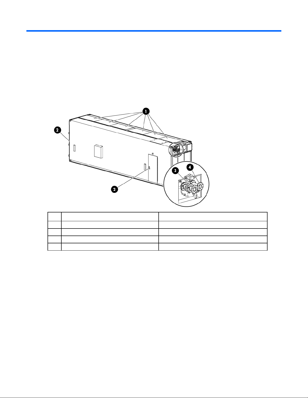
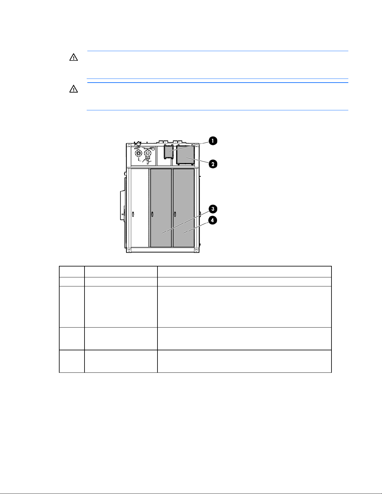
The HP POD 40c G2 documentation frequently refers to the specific components of the HP POD 40c G2 as
shown in the following figure and described in the following table.
Item Component Description
Heat exchanger access hatches Provides access to the overhead heat exchangers
1
Personnel access doors Provides access to the POD
2
Facility chilled water return Facilitates the return of chilled water to the POD
3
Facility chilled water supply Facilitates the supply of chilled water to the POD
4
Parts and part number identification
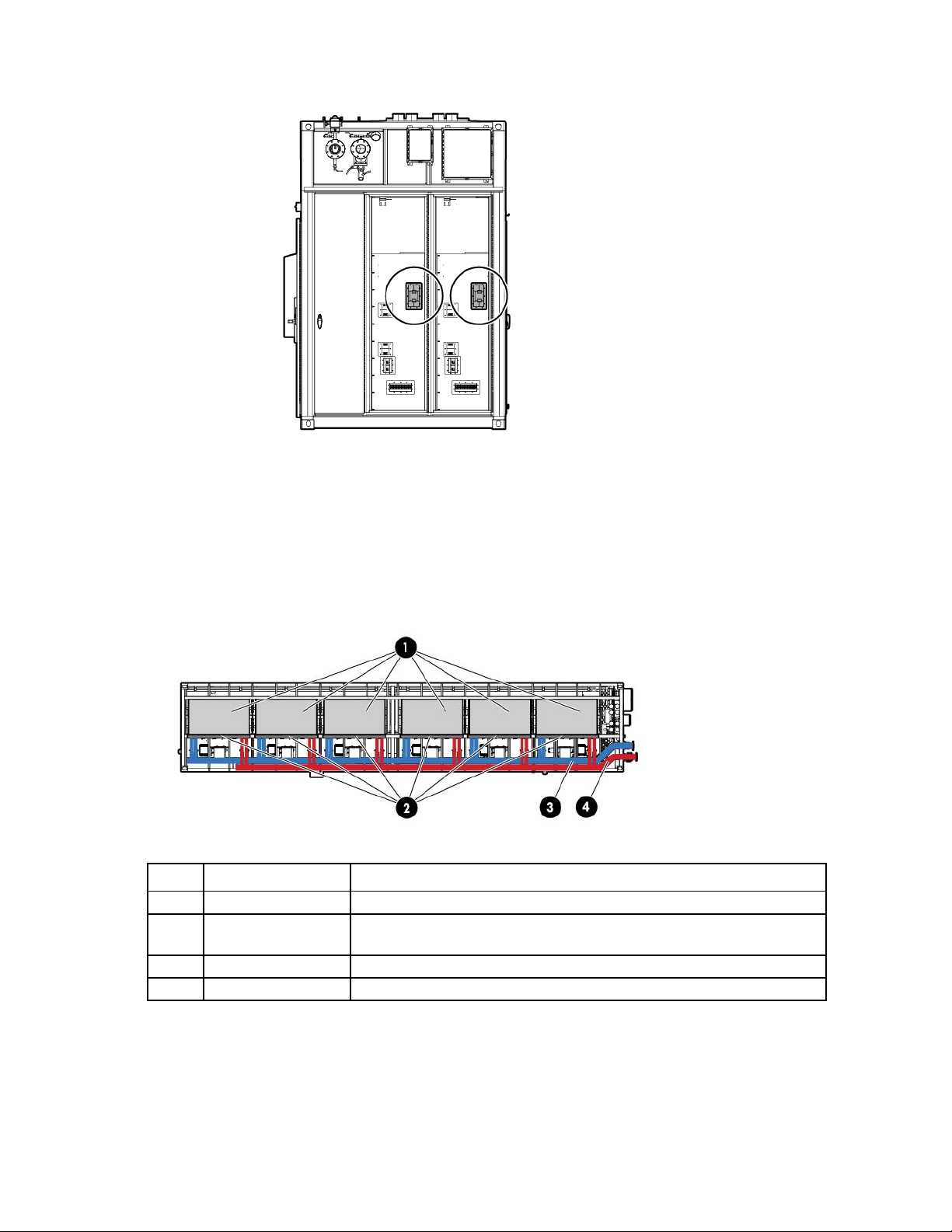
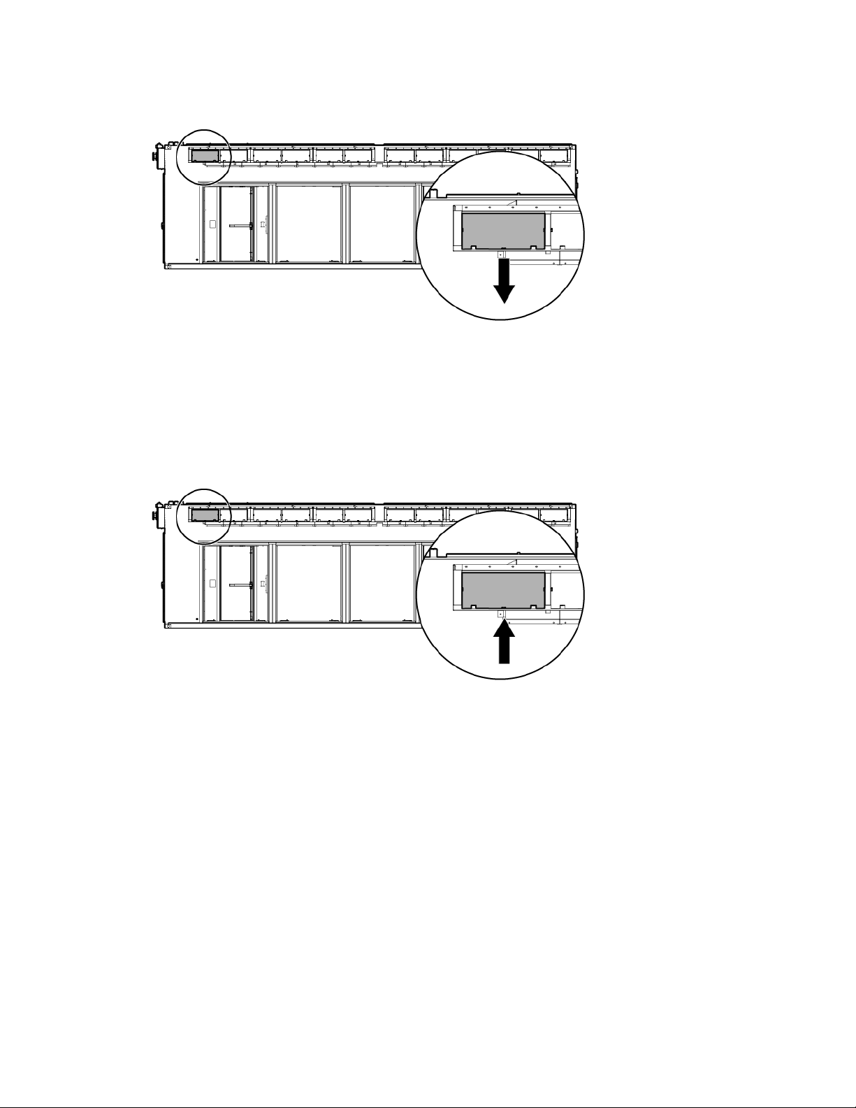
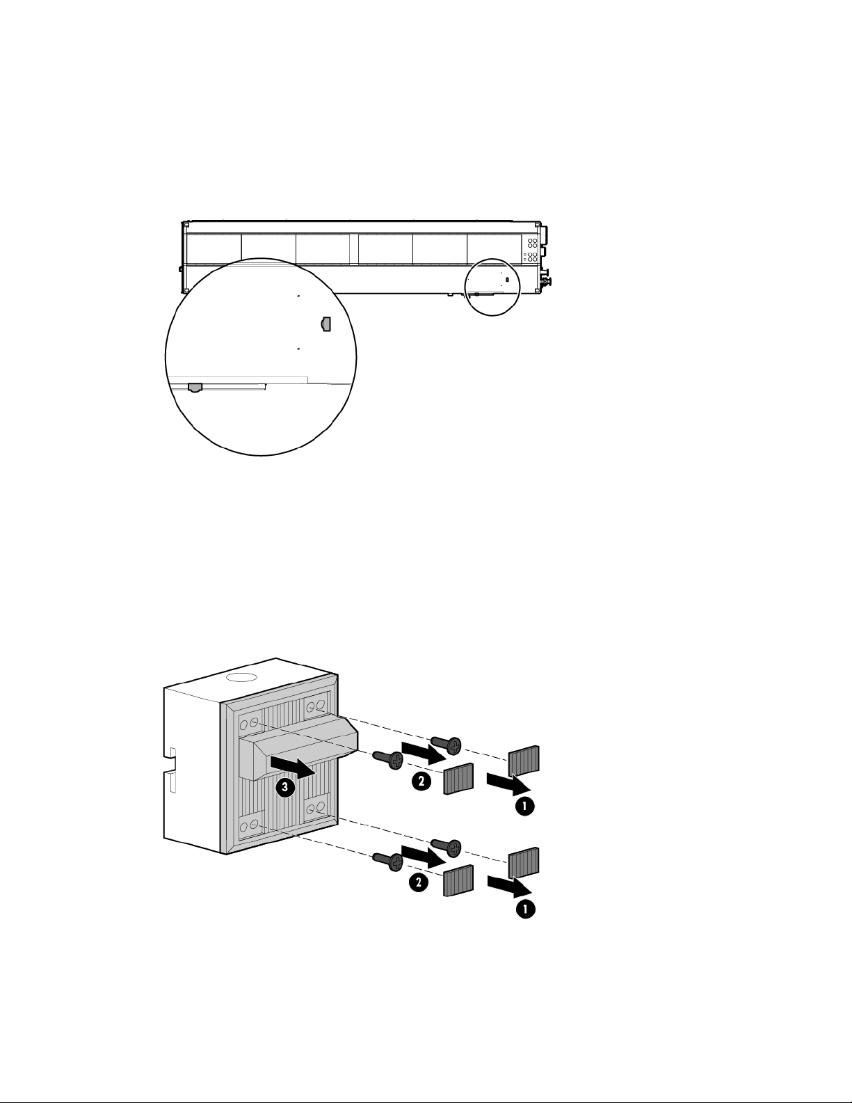
Review the contents of the HP POD 40c G2 to identify the following for each component:
• Model number—The model number is located on the door to the control panel inside the cold aisle of
the HP POD 40c G2, as shown in the following figure.
Illustrated parts catalog 6
Page 7
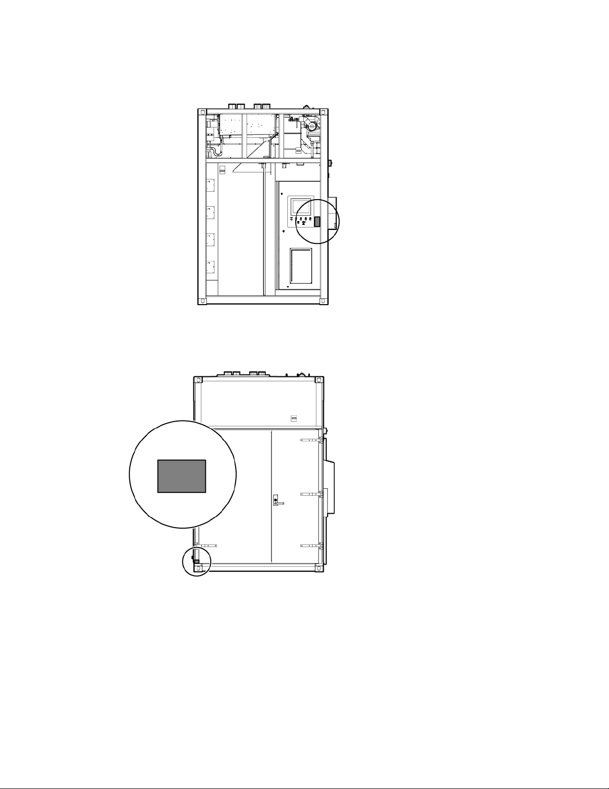
• Regulatory compliance identification number—This product has been assigned a unique regulatory
model number and is located on the door to the control panel inside the cold aisle of the HP POD 40c
G2, as shown in the following figure.
• CSC Safety Approval placard—Each HP POD 40c G2 has a CSC Safety Approval placard that includes
the model number, serial number, and proof load. The CSC Safety Approval placard is located on the
cargo end of the HP POD 40c G2, as shown in the following figure.
Life safety component identification
Internal life safety components
Illustrated parts catalog 7
Page 8
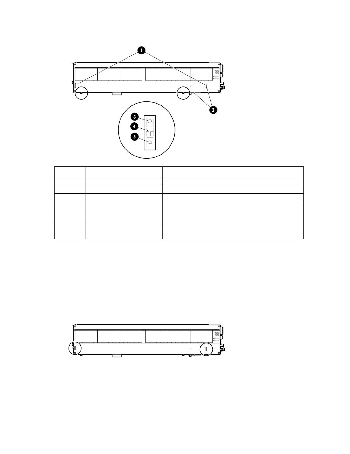
Top view shown
Item Component Description
1
2
3
4
5
*This is an optional component that might not be included.
Exit sign locations Indicates the location of an exit
Fire strobe light Indicates a fire alarm condition within the HP POD 40c G2
EPO button Disconnects the HP POD 40c G2 from main power feeds
Fire alarm manual pull* Enables manual initiation of the fire system, which includes
activating the interior and exterior fire strobe lights and the
optional fire suppression system
Fire suppression abort button* Aborts the fire suppression system. A fire suppression abort
button is located next to each personnel door.
Exit sign locations
The exit signs within the HP POD 40c G2 contain tritium. For information about the regulatory requirements
regarding the handling, transfer, and disposal of the signs, see "Regulatory requirements for EXIT signs (on
page 76)."
Top view shown
External emergency status indicators
The HP POD 40c G2 has one external fire strobe light that indicates a fire alarm condition.
Illustrated parts catalog 8
Page 9
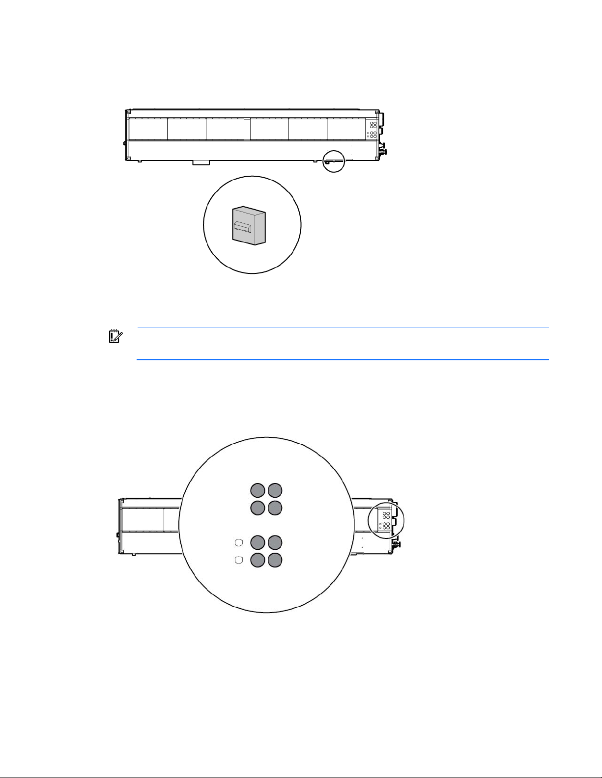
Top view shown
A licensed electrician must connect the power according to all local and national
Power feeders
IMPORTANT:
The HP POD 40c G2 has eight power feeder couplings that provide the entrance for power to the POD. The
power feeders route into the top of each electrical panel on the end of the HP POD 40c G2.
Top view shown
electrical codes, and must comply with manufacturer specifications.
The top of each electrical panel has four 10.16 cm (4 in) welded couplings where the power feeders are
connected.
Power feeders are sized in accordance with NEC and IEC regulations.
Illustrated parts catalog 9
Page 10
requirements when opening or working inside areas of the HP POD 40c G2 that are marked as
•
•
•
Electrical panels
WARNING: To avoid the risk of personal injury or loss of life, all personnel must comply with PPE
End view shown
hazardous voltage, per NFPA 70E in accordance with NEC (NA) and IEC (EMEA and APJ).
WARNING: To avoid the risk of personal injury or loss of life, all personnel must comply with
electrical warning labels when operating and maintaining the electrical panels and systems of the
HP POD 40c G2.
Item Component Description
1
2
Fire box* Connection location for fire emergency and VESDAnet signals
Demarcation box* Customer communication connection point for the following
components:
ECS
Security
Phone
3
415 Y/240 V 3-phase,
4-wire, 800 A electrical
panel
4
415 Y/240 V 3-phase,
4-wire, 800 A electrical
panel
*The demarcation box and the fire box are communication data points that are provided on the POD by HP. Connecting
these data points is the responsibility of the customer, unless an approved Statement of Work is initiated.
Feed A power for critical IT loads (electrical busways) and house power
Feed B power for critical IT loads (electrical busways) and house power
Main breaker locations
Illustrated parts catalog 10
Page 11
End view shown
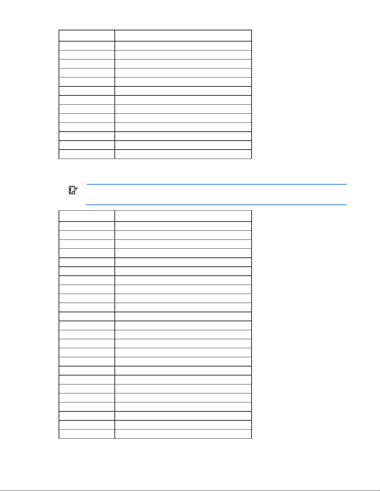
Cooling system component identification
The heat exchanger access hatches are located on top of the POD. The hatches are coated with a durable
finish to prevent corrosion.
Side view shown
Item Component Description
1
2
3
4
Heat exchangers Use facility chilled water to cool the air in the HP POD 40c G2
Heat exchanger fan
banks
Chilled water supply Supplies facility chilled water to cool the HP POD 40c G2
Chilled water return Returns heated chilled water to the facility
Operate at variable speeds to maintain the preprogrammed differential
pressure setpoint and the hot aisle temperature setpoint
HP POD 40c G2 racks
The HP POD 40c G2 contains a total of 20 IT racks.
Illustrated parts catalog 11
Page 12

CAUTION: If any racks contain empty RU space, use the HP POD 40c G2 filler panels to
SPS-TERMINAL SER INTFC RS4222 RS485
maintain the efficiency of the HP POD 40c G2 thermal system. Filler panels are available from HP
in 10-pack quantities (part number AQ682A) and 100-pack quantities (part number AS993A).
For more information about racks and network cabling, see the HP Performance Optimized Datacenter
Networking Guide.
Replaceable spare parts
The spare parts in the following table can be replaced by qualified facilities personnel.
Spare part number Description
660063-001
660064-001
637086-001
637087-001
637088-001
637089-001
637090-001
637091-001
637092-001
637093-001
637094-001
637095-001
637096-001
637097-001
637098-001
637099-001
637100-001
637101-001
637102-001
637103-001
637104-001
637118-001
637119-001
637120-001
637121-001
637122-001
637123-001
637124-001
637129-001
637131-001
637134-001
637135-001
637136-001
637137-001
3-phase, 20A busway drop box; NA POD
3-phase, 60A busway drop box; NA POD
SPS-FUSE BLOCK 600V 3P
SPS-FUSE BLOCK 600V 1P
SPS-CPU TOUCH SCREEN
8 port ETHERNET SWITCH
SPS-TERMINAL DIGITAL OUTPUT 4CH
SPS-TERMINAL END BUS EXT
SPS-TERMINAL BUS TERM ETHERCAT
SPS-TERMINAL COUPLER ETHERCAT
SPS-ANALOG INPUT 4 20mA 4CH
SPS-TERMINAL ANALOG OUTPUT 0-10V 2CH
SPS-TERMINAL BUS END
SPS-TERMINAL PRESSURE DIFF 1CH
SPS-TERMINAL DIGITAL INPUT 4CH
SPS-TERMINAL 100PT INPUT 4CH
SPS-SIREN 24V DC
White LED light
Yellow LED light
Red LED light
SPS-RELAY 4POLE 2NC 240VAC
SPS-SOCKET RELAY LOGIC 4POLE
SPS-SENSOR TEMP POD
SPS-FUSE ATDR TIME DELAY 600VAC 1A
SPS-FUSE ATDR TIME DELAY 600VAC 4A
SPS-FUSE ATDR TIME DELAY 600VAC 10A
SPS-RELAY 4POLE 24V DC 10A
SPS-TSAT 60
SPS-MAGNETIC FLOW METER
NETWORK INTERFACE CARD
SPS-SENSOR TEMP INSERTION
SPS-SENSOR PRESSURE ABS 10 BAR
SPS-SENSOR TEMP ROOM
Illustrated parts catalog 12
Page 13
Spare part number Description
SPS-SENSOR TEMP RH NEMA 4 4 20mA OUT
A licensed electrician must connect the power according to all local and national
SPS-PWR SPLY SNGL ZONE 220VAC VESDA
637138-001
637139-001
637140-001
637141-001
637371-001
637372-001
637373-001
664744-001
664868-001
671748-001
671749-001
671756-001
VS-005 (Mfg PN)
EPO switch cover w/ horn
EPO BUTTON
ELECTRIC VALVE ACTUATOR
BUTTERFLY VALVE
SPS-FAN 235 CFM
Temperature sensor duct
SPS-SENSOR LEAKAGE
SPS-INDICATOR LED 6 24VDC GREEN
SPS-SENSOR PRESSURE GAUGE 160 PSI
SPS-SENSOR FLOW METER GEMU
SPS-HUMIDISTAT GEN M3
Filter, replacement, VESDA, Laser Series
The spare parts in the following table are electrical components that must be replaced by a certified
electrician.
IMPORTANT:
electrical codes, and must comply with manufacturer specifications.
Spare part number Description
637117-001
637126-001
637128-001
637130-001
637132-001
637142-001
637143-001
637144-001
637145-001
637146-001
637496-001
664738-001
664748-001
671746-001
671750-001
671751-001
671752-001
671755-001
671757-001
671759-001
671760-001
671761-001
671762-001
671763-001
SPS-CKT BKR T2 100AF 40AT
SPS-CKT BKR T4 200A 600V 3POLE
SPS-POWER METER PAC 3200
SPS-TRANSFORMER CT PANEL MT
SPS-TVSS
SPS-SHUNT TRIP 800A CKT BRKR
SPS-CKT BREAKER SMD 3P 800A
24V UPS power supply
SPS-PWR SUPPLY REDUNDANT MOD
SPS-PWR SUPPLY 24V 7ah ACCUMULATOR
230V power supply
SPS-TRANSFORMER 2000VA 240x480 120x240
SPS-TRANSFORMER CT 3 PHASE
SPS-HOUSING LED LIGHT FXTR
SPS-LED LIGHT FXTR ASSY
SPS-FUSE TIME DELAY
SPS-CONTACT MAG DOOR
SPS-HUMIDIFIER 230VAC
SPS-CKT BRKR SNGL POLE 15A
SPS-CKT BRKR MINI 5A
SPS-CKT BRKR MINI 20A
SPS-CKT BRKR BRANCH SNGL POLE 10A
SPS-CKT BRKR 3P MAIN LUG 150A
Illustrated parts catalog 13
Page 14

The spare parts in the following table must be replaced by a licensed fire safety contractor.
These parts must be replaced by a licensed fire safety contractor according to all
IMPORTANT:
local and regional fire codes, and in compliance with manufacturer specifications.
Spare part number Description
637133-001
Smoke detector
Illustrated parts catalog 14
Page 15

Removal and replacement procedures
requirements when opening or working inside areas of the HP POD 40c G2 that are marked as
Safety considerations
The HP POD 40c G2 is listed to the UL 69050 standard as an Information Technology Product and Classified
according to the NEC, NFPA-70, 2008.
The HP POD 40c G2 is not suitable for long term personnel occupancy.
The safety information is specific to the people operating and maintaining the components of the HP POD
40c G2.
IMPORTANT: All plumbing to and from the HP POD 40c G2 must be completed by a licensed
plumber.
IMPORTANT: All wiring in and around the HP POD 40c G2 must be completed by a licensed
electrician.
Operator safety
The HP POD 40c G2 provides service access areas for periodic maintenance and service and is only to be
used by owner-authorized personnel specifically trained in the maintenance and service of the HP POD 40c
G2.
The HP POD 40c G2 is not a habitable structure suitable for long term personnel occupancy.
WARNING: To avoid the risk of personal injury or loss of life, all personnel must comply with PPE
The customer is responsible for completing any Environmental Health and Safety (EHS) evaluation of the HP
POD 40c G2 or any attached structural component purchased through HP. The customer must complete an
arc flash assessment of the HP POD 40c G2 and the associated electrical supply system for operation,
maintenance, and so on.
hazardous voltage, per NFPA 70E in accordance with NEC (NA) and IEC (EMEA and APJ).
WARNING: To avoid the risk of personal injury, hearing protection must be worn at all times
when working inside the HP POD 40c G2.
WARNING: To avoid the risk of personal injury or damage to the equipment, do not insert
anything inside the electrical busways except the approved HP busway drop boxes.
Fire detection and suppression
The fire suppression system, supplied as an optional component of the HP POD 40c G2, is a "Manufacturer
Designed" system specifically for this HP product, in compliance with national standards.
Removal and replacement procedures 15
Page 16
The HP standard suppression system includes a Novec 1230 clean agent system. However, if the customer
or local AHJ requires specific modifications or a replacement, HP can assist in these actions at the expense
of the customer.
HP does not certify that the fire suppression system installed in the HP POD 40c G2 meets all local and
jurisdictional requirements. The customer is responsible for the following actions as related to the fire
suppression system:
• Verifying that the POD suppression system meets local codes, including specific local requirements for
initial and periodic inspections.
• Arranging for and receiving all required local permits, including initial commissioning as well as
standard and repair maintenance.
• Arranging for the connection of the agent tanks, refilling of tanks, and all system testing, including
pressure tests. All general maintenance of the suppression system must be completed by an authorized
technician.
Additional local requirements are not covered as part of the option price or basic installation and
deployment services, unless specifically included in an executed Statement of Work.
Air filter
There are 2 air filters per cooling zone, for a total of 12 filters.
Tools are not required for installation.
Removing the air filter
1. Pull the locking tabs away from the air filter to release the filter.
Removal and replacement procedures 16
Page 17
2.
Pull the filter down through the frame channels to remove the filter.
Replacing the air filter
1. Angle the filter to position the top corners in the frame channels, and then push the filter up to the top of
the frame.
2. Press in the bottom corners of the filter until the locking tabs engage and the filter clicks into place.
Removal and replacement procedures 17
Page 18
Busway drop box
The internal electrical busways provide a location to connect each of the drop boxes, which then power the
PDUs. Stagger the drop boxes on the electrical busways by connecting one drop box to busway #1 and
connecting the next drop box to busway #2. A staggered configuration enables load balancing with the rack
equipment and is necessary to ensure redundancy.
You need a socket wrench for installation.
IMPORTANT: HP recommends that you shut down the associated IT equipment and de-energize
the appropriate section of the power busway before attempting to remove or replace a busway
drop box. The corresponding branch circuit breaker is labeled on the busway.
Removing the busway drop box
1. Turn the power off by opening both breakers on the busway drop box (1).
2. Disconnect the PDUs that are connected to the busway drop box (2).
3. Use a socket wrench to loosen and remove the bolt securing the busway drop box to the retaining
hardware bracket (1).
Removal and replacement procedures 18
Page 19
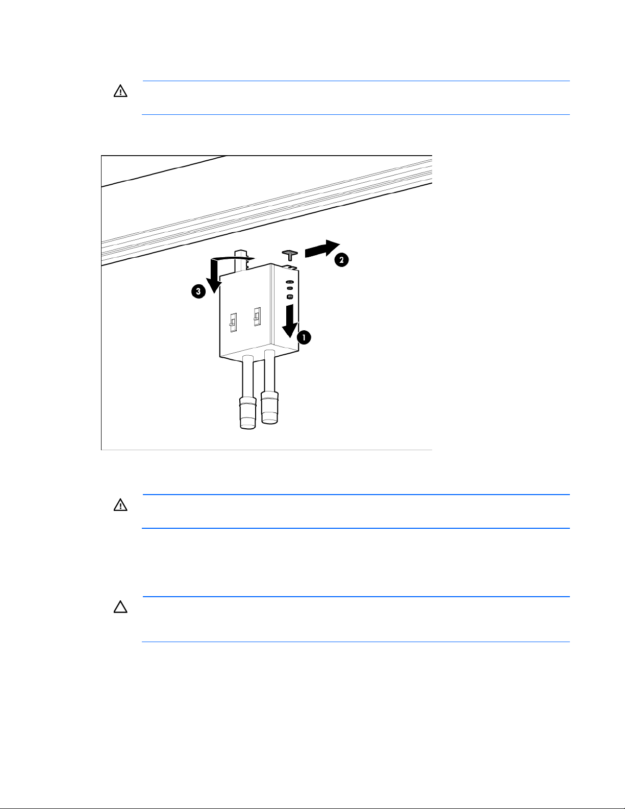
4.
Slide the hardware bracket to the right along the busway, completely disconnecting it from the busway
drop box (2).
WARNING: Use caution when removing and replacing the busway drop box. The drop box
weighs approximately 9 kg (20 lb).
5. Rotate the busway drop box 90° so that it is perpendicular to the electrical busway, and then remove
the drop box from the electrical busway (3).
Replacing the busway drop box
WARNING: Use caution when removing and replacing the busway drop box. The drop box
1. Place the silver drop box bracket onto the electrical busway where you want to replace the busway
2. Note the required rotation indicated on the drop box, insert the drop box into the drop box bracket on
3. Slide the hardware bracket to the left along the busway until it connects to the drop box (3).
weighs approximately 9 kg (20 lb).
drop box (1).
the electrical busway, and then rotate the drop box 90° until it locks into place (2).
CAUTION: To prevent damage to the drop box and ensure that the drop box engages properly,
be sure that the drop box is completely flush to the busway. If a drop box is damaged during
installation, do not attempt to re-engage or repair the drop box.
Removal and replacement procedures 19
Page 20
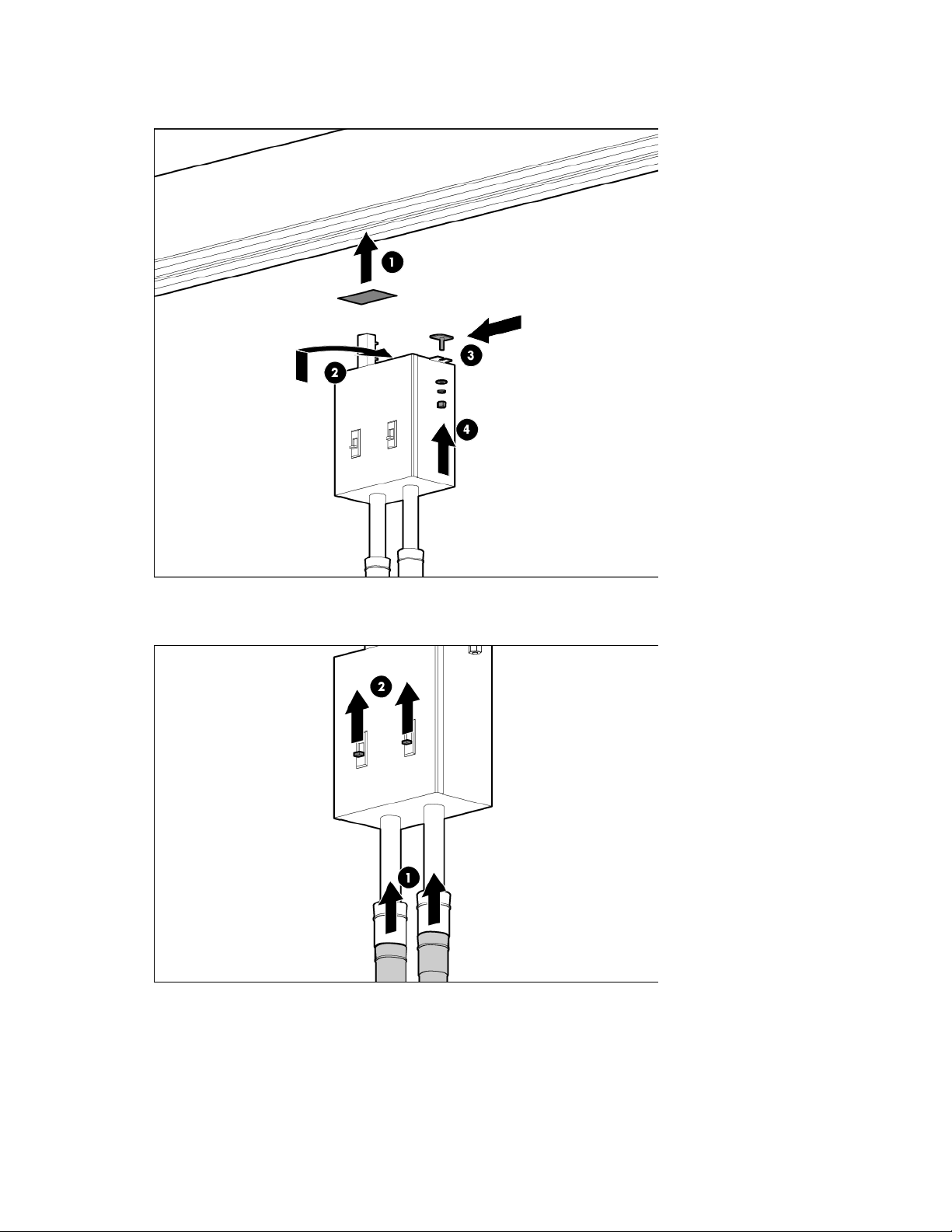
4.
Secure the busway drop box to the retaining hardware bracket by using a socket wrench to insert and
tighten a bolt (4).
5. Connect the PDUs to the busway drop box (1).
6. Turn the power on by closing both breakers on the busway drop box (2).
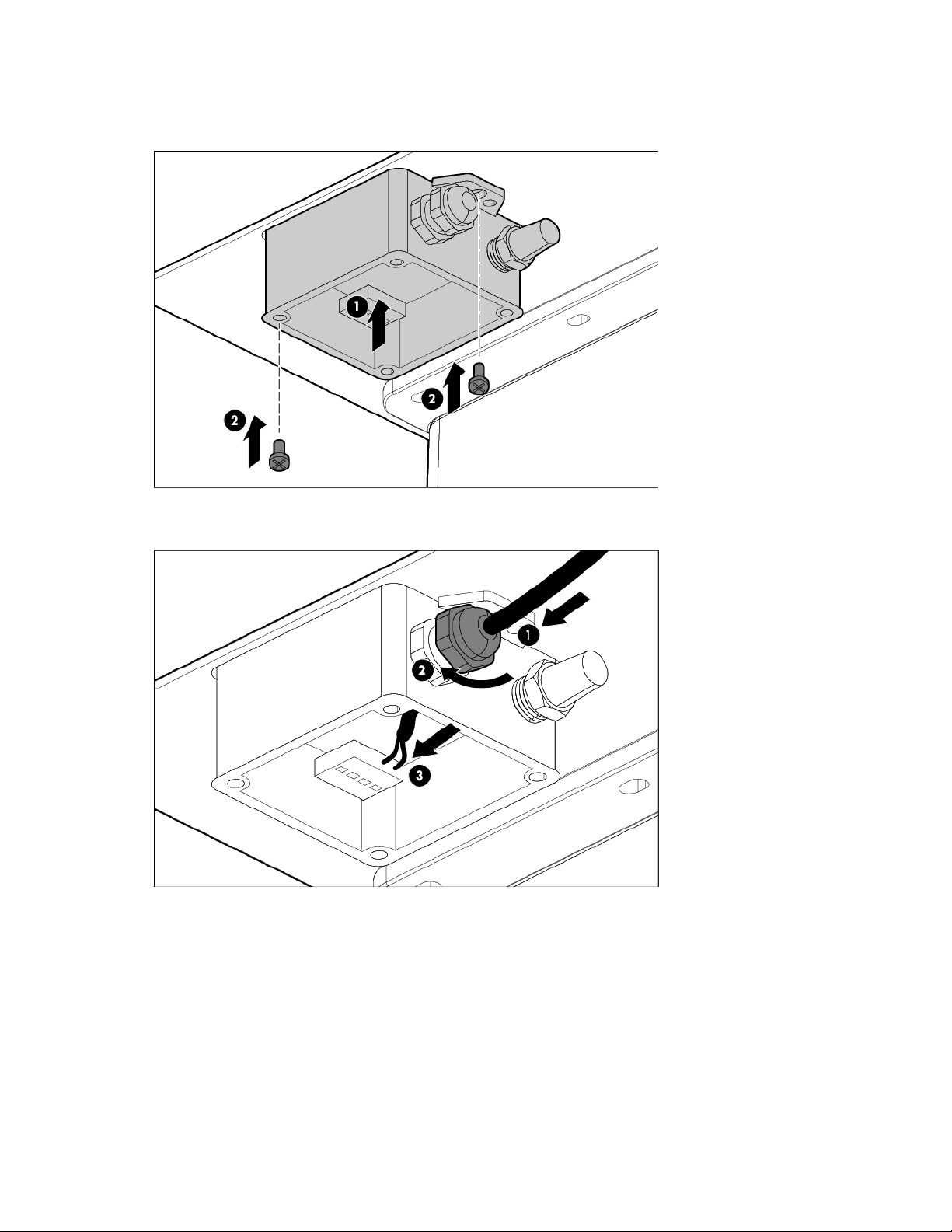
Differential pressure sensor
The differential pressure sensors are located in the cold aisle.
You need a Phillips-head screwdriver for installation.
Removal and replacement procedures 20
Page 21
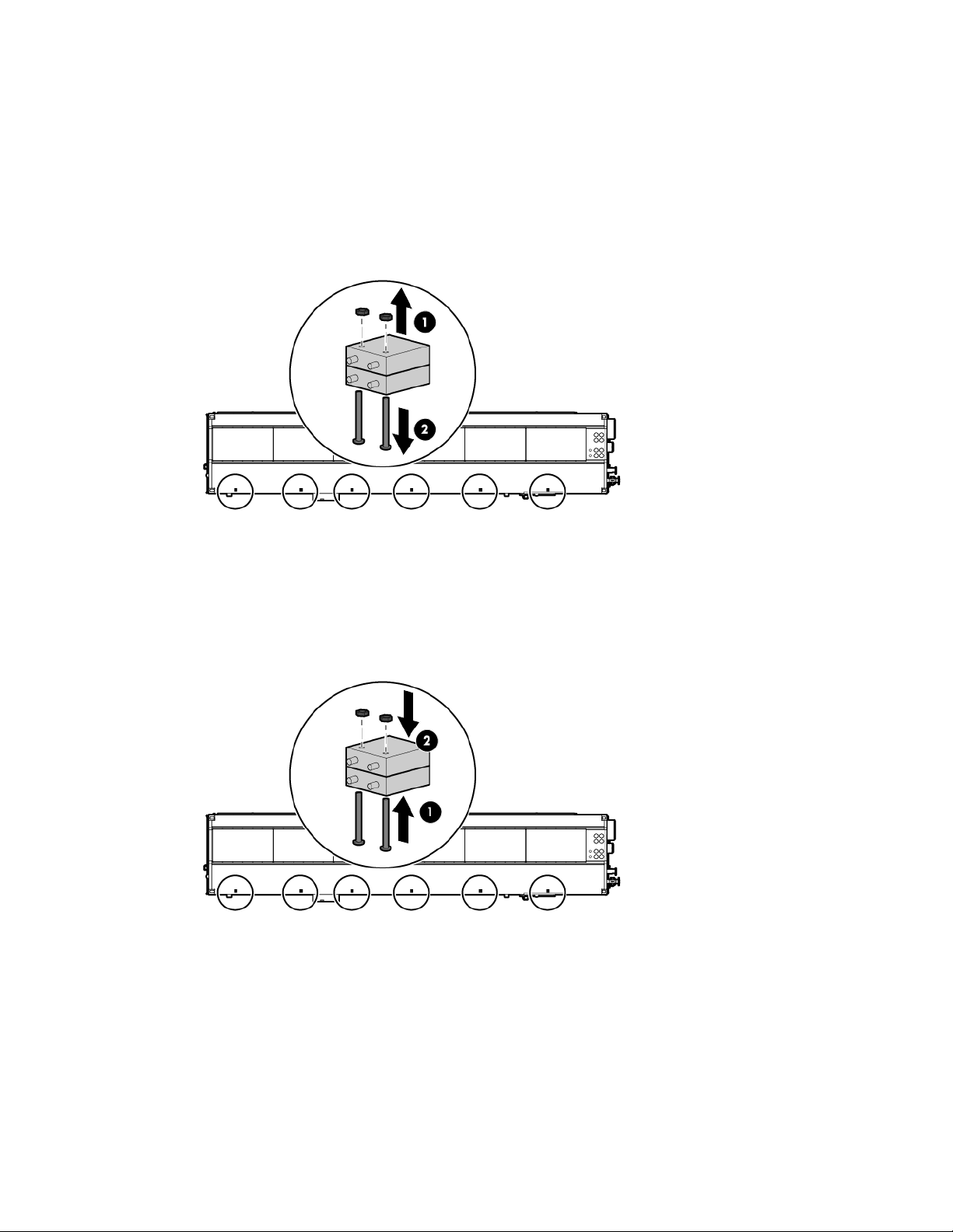
Removing the differential pressure sensor
1. Label the pressure sensor tube connection locations, and then remove the tubes from the differential
pressure sensor.
2. Label the sensor wire connection locations, loosen the screws securing the sensor wires, and then
remove the sensor wires.
3. Remove the two nuts (1) and two bolts (2) securing the differential pressure sensor, and then remove the
differential pressure sensor.
Replacing the differential pressure sensor
1. Replace the differential pressure sensor, and then secure the differential pressure sensor with two bolts
(1) and two nuts (2).
2. Insert the pressure sensor tubes into the differential pressure sensor according to the connection
locations you labeled during the removal procedure.
3. Replace the sensor wires according to the connection locations you labeled during the removal
procedure, and then secure the sensor wires by tightening the screws.
Removal and replacement procedures 21
Page 22
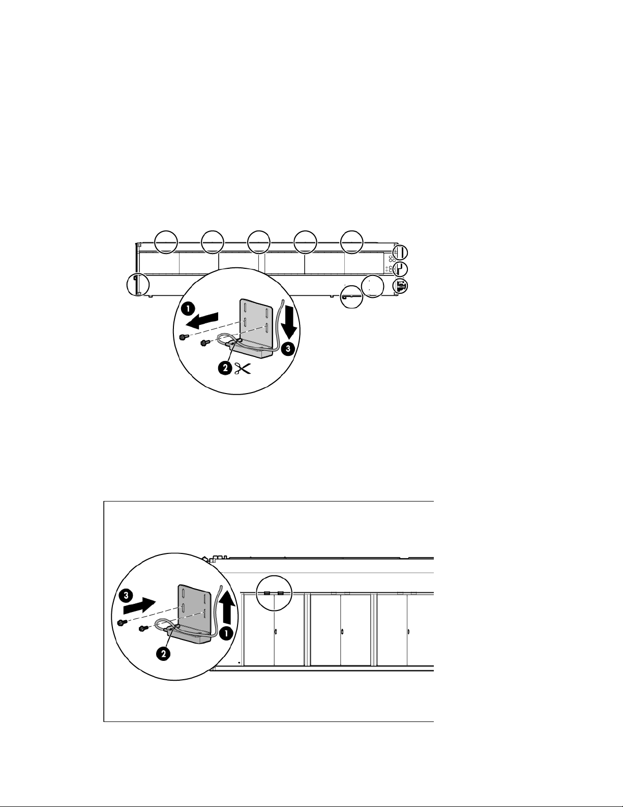
Door position contact
Door position contacts are located on all doors and cabinets.
You need a Phillips-head screwdriver and scissors for installation.
Removing the door position contact
1. Remove the two screws securing the upper magnet (1).
2. Cut the tie wrap (2) and loosen the nut on the HP POD 40c G2 structure that secures the wire.
3. Pull the wire all the way through to the point of entry or ECS panel (3).
Replacing the door position contact
1. Feed the wire all the way through from the point of entry or ECS panel (1).
2. Tighten the nut on the HP POD 40c G2 structure that secures the wire, and then replace the tie wrap (2).
3. Secure the magnet to the bracket using two screws (3).
Removal and replacement procedures 22
Page 23

Drain pan sensor
The HP POD 40c G2 includes six heat exchanger condensate drains. One drain pan sensor is located in the
drain tray below each set of heat exchangers.
Two sensors are also located in the header drain pans, one in cooling zone 2 and one in cooling zone 5.
The normally-open circuit is closed when the probes of the drain pan sensor become wet, which allows 24
VDC to travel back to the ECS panel and trigger the alarm.
You need a Phillips-head screwdriver and a small flathead screwdriver for installation.
Removing the drain pan sensor
1. If you are removing a heat exchanger drain pan sensor, do the following:
a. Inspect the area by removing the center, bottom fan from the center fan bank in the associated zone.
For more information, see "Removing the fan (on page 38)."
b. To gain additional working space, you might need to remove a fan bank in the associated zone. For
more information, see "Removing the fan bank (on page 40)."
2. Follow the sensor wire to the associated satellite box. Disconnect the wire from the satellite box terminal
and note the wire location.
Heat exchanger drain pan sensor
-orHeader drain pan sensor
Removal and replacement procedures 23
Page 24

3.
Pull the wire through from the satellite box to the sensor location, and then remove the sensor.
Heat exchanger drain pan sensor
-orHeader drain pan sensor
Replacing the drain pan sensor
1. Position the sensor in the drain pan.
Heat exchanger drain pan sensor
-or-
Removal and replacement procedures 24
Page 25

Header drain pan sensor
2. Route the wire through the flex tubing to the associated zone satellite box.
3. Connect the sensor wire to the appropriate port on the satellite box terminal.
Heat exchanger drain pan sensor
-orHeader drain pan sensor
4. If you are replacing a heat exchanger drain pan sensor, do the following:
a. Replace the fan bank you removed, if applicable. For more information, see "Replacing the fan
bank (on page 41)."
b. Replace the fan you removed, if applicable. For more information, see "Replacing the fan (on page
39)."
Removal and replacement procedures 25
Page 26
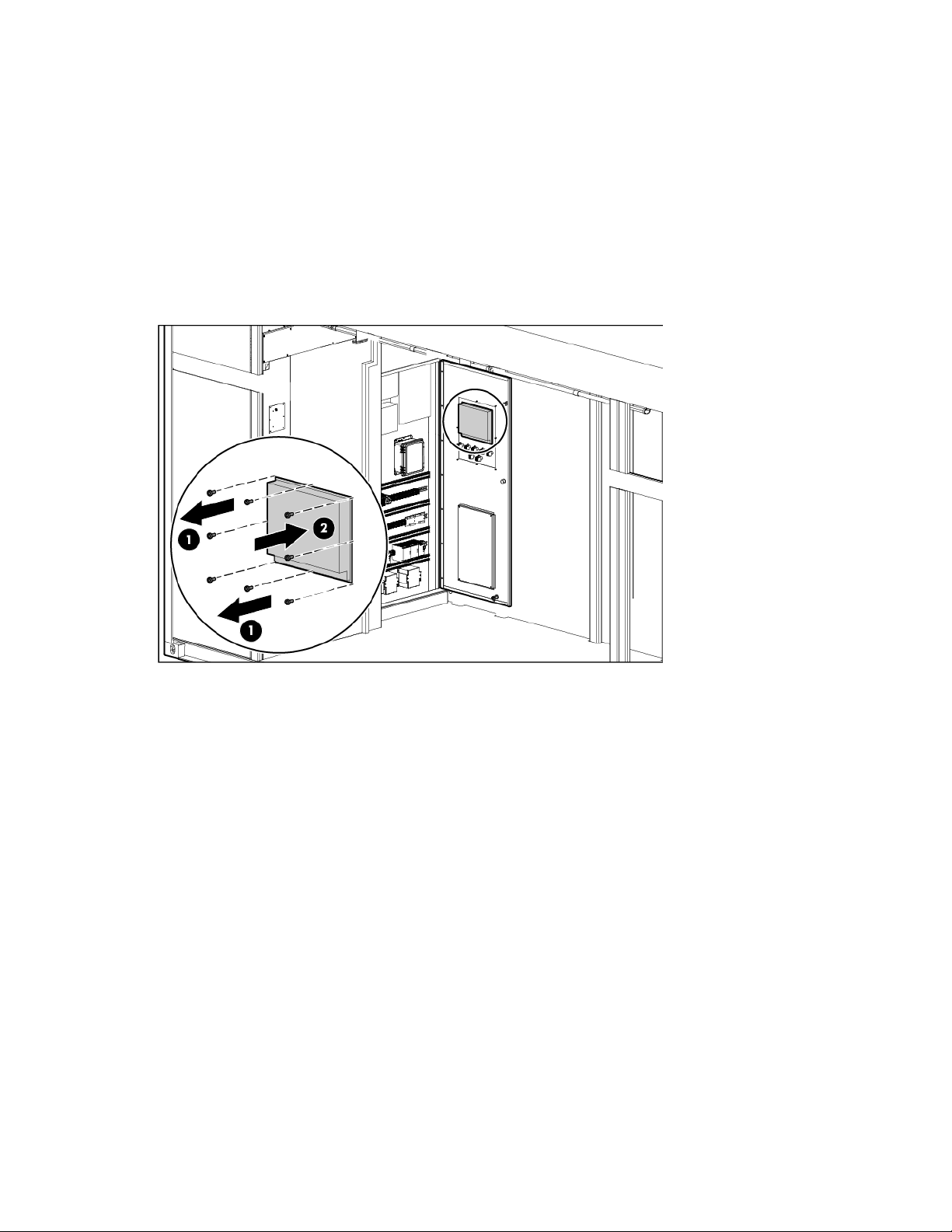
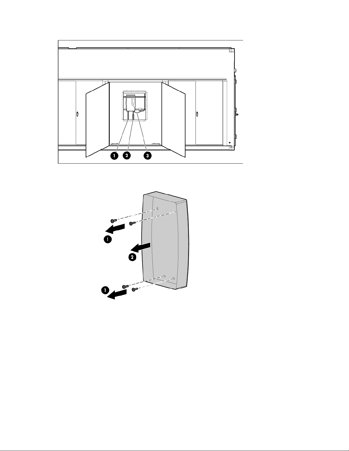
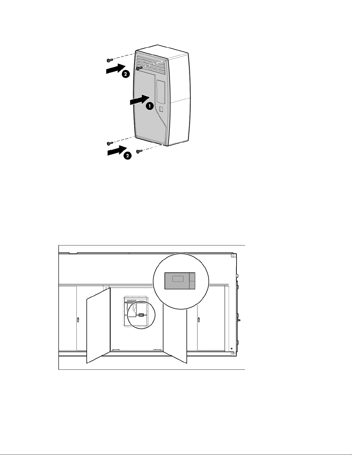
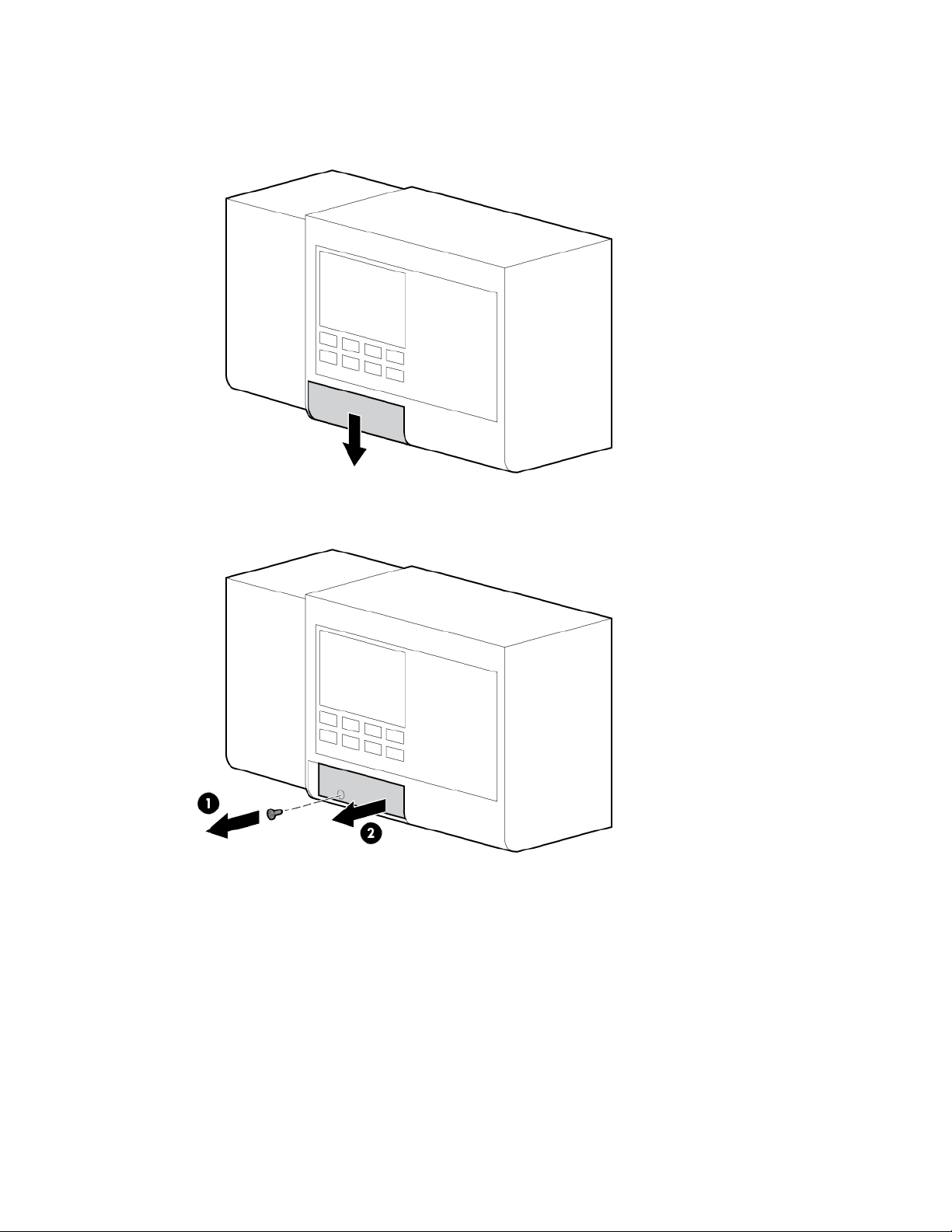
ECS touchscreen
The ECS touchscreen is located on the door to the control panel inside the cold aisle of the HP POD 40c G2.
You need a Phillips-head screwdriver for installation.
Removing the ECS touchscreen
1. Disconnect the cables attached to the back of the ECS touchscreen.
2. Remove the eight screws on the back of the door that secure the ECS touchscreen (1), and then push the
ESC touchscreen through the front of the door to remove the ECS touchscreen (2).
Removal and replacement procedures 26
Page 27

Replacing the ECS touchscreen
1. Replace the ESC touchscreen through the front of the door (1), and then secure the ECS touchscreen to
the back of the door with eight screws (2).
2. Connect the cables to the back of the ECS touchscreen.
EPO button
There are two EPO buttons, one by each personnel access door in the HP POD 40c G2.
You need a Phillips-head screwdriver for installation.
Removal and replacement procedures 27
Page 28
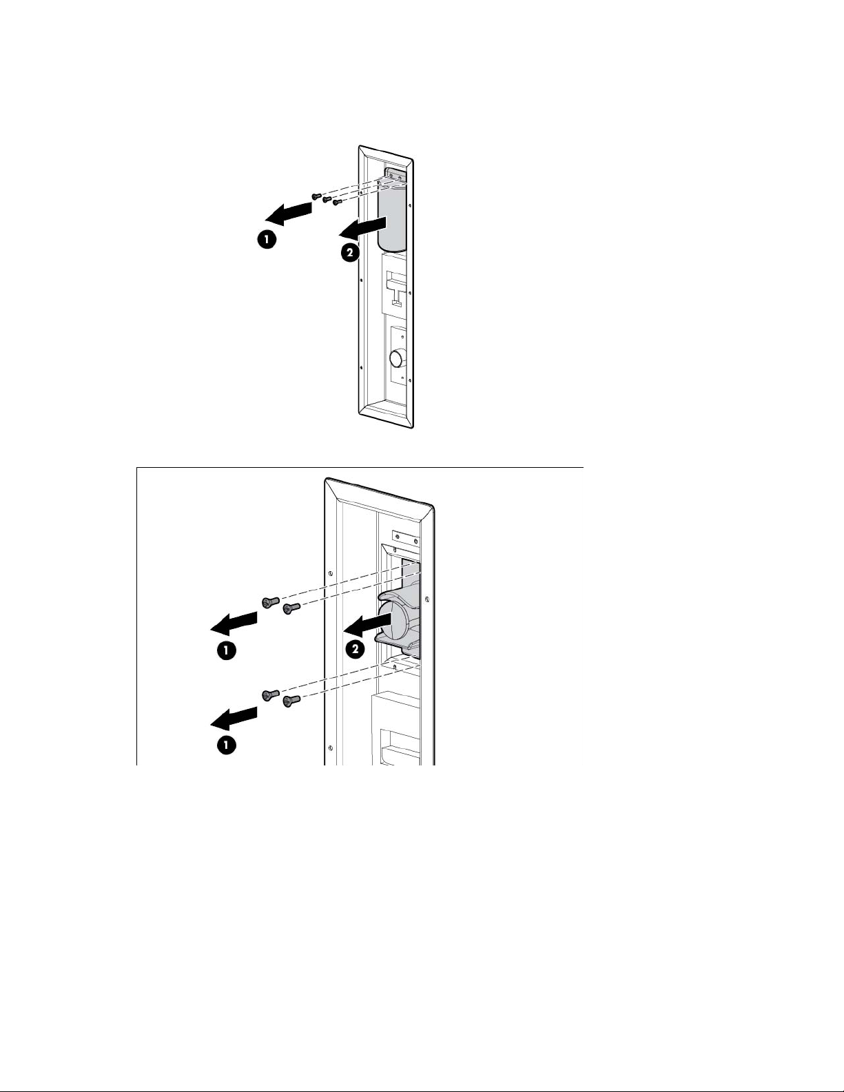
Removing the EPO button
1. Remove the two screws securing the tamper cover (1), and then remove the tamper cover (2).
2. Remove the four screws securing the EPO button (1), and then remove the EPO button (2).
Removal and replacement procedures 28
Page 29
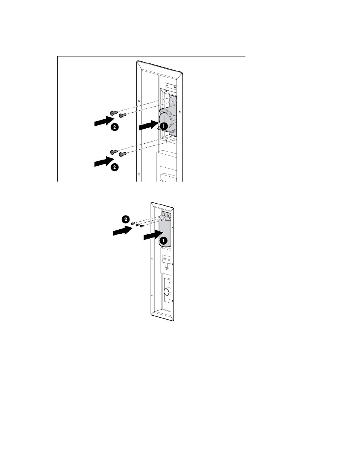
Replacing the EPO button
1. Replace the EPO button (1), and then replace the four screws that secure the EPO button (2).
2. Replace the tamper cover (1), and then replace the two screws that secure the tamper cover (2).
Removal and replacement procedures 29
Page 30
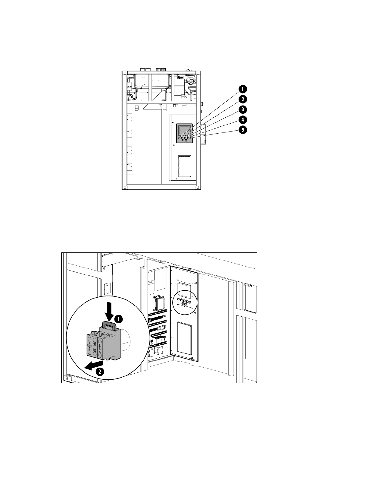
EPO LED indicators
The ECS cabinet contains white (1, 3), red (2), yellow (4), and green (5) EPO LED indicators.
Tools are not required for installation.
Removing the EPO LED indicator
1. On the back of the ECS cabinet door, push the gray tab on the EPO LED indicator module down to
release the module (1), and then pull the module out of the door (2).
Removal and replacement procedures 30
Page 31
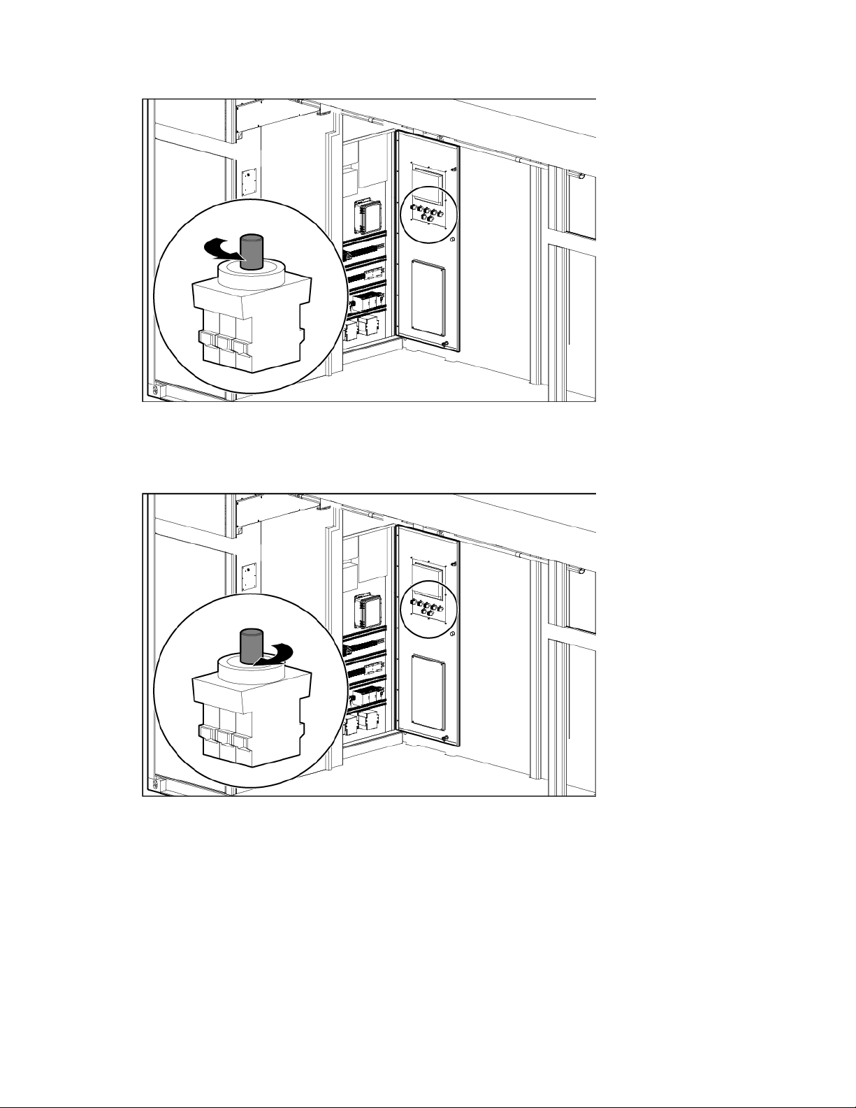
2.
Unscrew the EPO LED indicator bulb.
Replacing the EPO LED indicator
1. Screw the new EPO LED indicator bulb into the module.
Removal and replacement procedures 31
Page 32

2.
Push the module into the slot on the back of the ECS cabinet door until it clicks into place.
EPO thermister
Two EPO thermisters are located in the hot aisle, one in cooling zone 2 and one in cooling zone 5.
While the thermisters are not technically at-temperature monitoring devices, when the hot aisle temperature
reaches 60ºC (140ºF), the thermister switch closes. When both thermister switches are closed, the EPO
system initiates an emergency shutdown.
Removing the EPO thermister
You need scissors for installation.
1. Cut the tie wraps securing the thermister (1).
2. Pull the thermister down to remove the thermister (2).
Replacing the EPO thermister
1. Insert the replacement thermister (1).
Removal and replacement procedures 32
Page 33

2.
Secure the thermister with tie wraps (2).
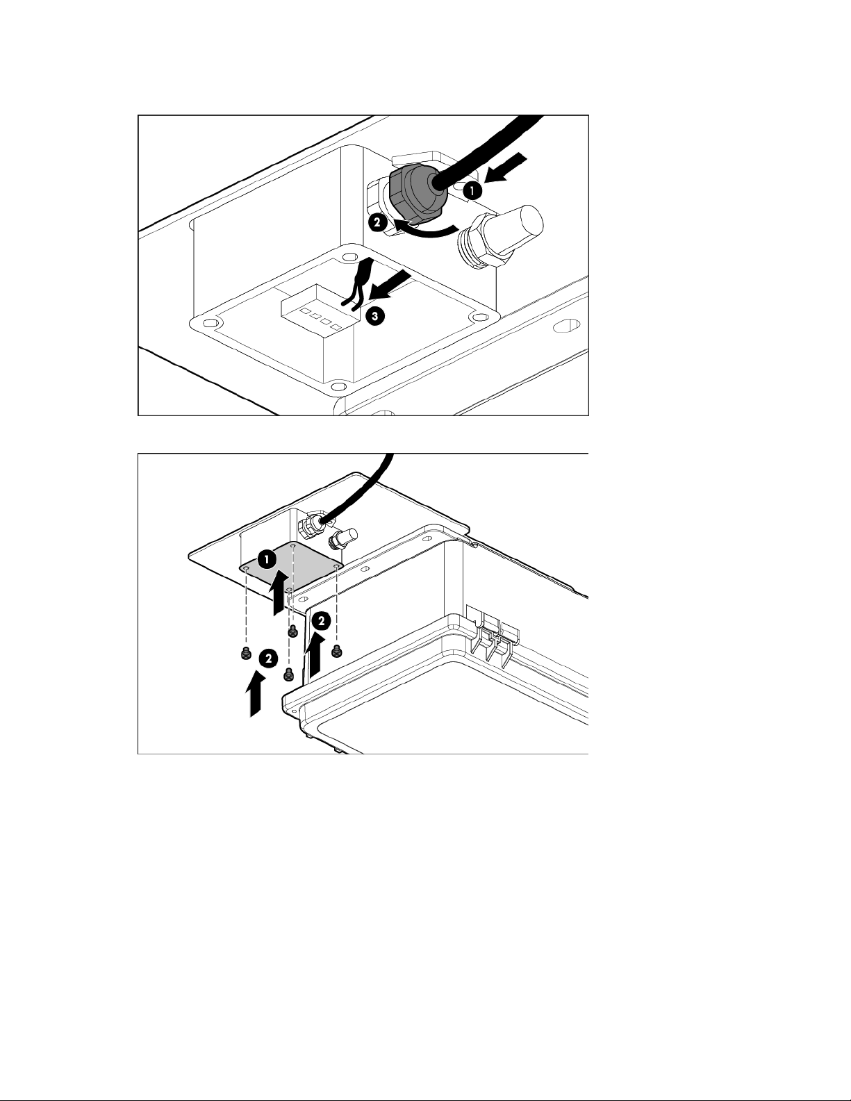
External chilled water flow actuator
The external chilled water flow actuator is located on top of the HP POD 40c G2.
You need a wrench for installation.
Removing the external chilled water flow actuator
1. Open and danger tag the associated circuit breaker in the ECS cabinet. The circuit breakers are
identified on the panel schedule.
Removal and replacement procedures 33
Page 34

2.
Remove the four bolts securing the face plate (1), and then remove the face plate (2).
3. Disconnect the power to the actuator.
4. Remove the four bolts securing the actuator (1), and then remove the actuator (2).
Removal and replacement procedures 34
Page 35

Replacing the external chilled water flow actuator
1. Replace the actuator (1), and then secure the actuator using four bolts (2).
2. Connect the power to the actuator.
3. Replace the actuator face plate (1), and then secure the face plate with four bolts (2).
4. Close the associated circuit breaker in the ECS cabinet.
External chilled water flow valve
The external chilled water flow valve is the butterfly valve located on top of the HP POD 40c G2.
You need a wrench for installation.
Removal and replacement procedures 35
Page 36

Removing the external chilled water flow valve
1. Remove the external chilled water flow actuator. For detailed instructions, see "Removing the external
chilled water flow actuator (on page 33)."
2. Remove the eight bolts surrounding the valve (1), and then remove the valve (2).
Replacing the external chilled water flow valve
1. Replace the valve (1), and then secure the valve with eight bolts (2).
2. Replace the external chilled water flow actuator. For detailed instructions, see "Replacing the external
chilled water flow actuator (on page 35)."
Removal and replacement procedures 36
Page 37

External pressure gauge isolation valve
The external pressure gauge isolation valve is located on top of the HP POD 40c G2.
You need an adjustable wrench or an appropriately sized box wrench for installation.
Removing the external pressure gauge isolation valve
Loosen the connection securing the valve (1), and then remove the valve (2).
Replacing the external pressure gauge isolation valve
Insert the new valve (1), and then tighten the connection (2).
Removal and replacement procedures 37
Page 38
Fan
Power must be removed from the fan power assembly before removing or replacing
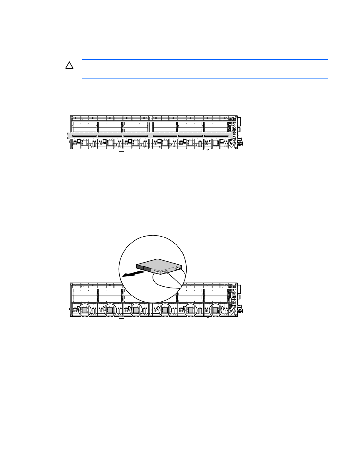
There are 18 fans per cooling zone.
CAUTION:
a fan or fan bank.
You need a Phillips-head screwdriver for installation.
Removing the fan
1. Disconnect both power supplies from the fan power assembly.
Removal and replacement procedures 38
Page 39

2.
Remove the three screws that secure the fan in the assembly (1), and then partially remove the fan by
pulling it straight out (2).
3. Disconnect the wire.
4. Remove the fan from the assembly.
Replacing the fan
1. Connect the wire.
2. Insert the fan into the assembly and push until the fan is fully seated (1).
3. Secure the fan with three screws (2).
4. Connect the power supplies to the fan power assembly.
Removal and replacement procedures 39
Page 40

Fan bank
Power must be removed from the fan power assembly before removing or replacing
There are three fan banks per cooling zone.
You need a Phillips-head screwdriver for installation.
CAUTION:
a fan or fan bank.
Removing the fan bank
1. Disconnect both power supplies from the fan power assembly.
2. Remove the fan bank wire harness (1).
3. Remove the six screws that secure the fan bank (2).
Removal and replacement procedures 40
Page 41

4.
Remove the fan bank by pulling it straight out (3).
Replacing the fan bank
1. Insert the fan bank (1).
2. Secure the fan bank with six screws (2).
3. Replace the fan bank wire harness (3).
4. Connect the power supplies to the fan power assembly.
Removal and replacement procedures 41
Page 42
Fire strobe light
The HP POD 40c G2 contains an internal fire alarm strobe light in the cold aisle and an external fire alarm
strobe light at the standard personnel entry door.
You need a Phillips-head screwdriver for installation.
Removing the fire strobe light
1. Remove the four screw cover plates (1).
2. Remove the four screws securing the components (2), and then disconnect the wiring.
3. Remove the electric sounder with strobe, the semi-flush plate, and the standard back box (3).
Removal and replacement procedures 42
Page 43

Replacing the fire strobe light
1. Assemble the standard back box, the semi-flush plate, and the electric sounder with strobe (1), and then
attach the wiring.
2. Secure the components with four screws (2).
3. Attach the four screw cover plates (3).
Humidifier
The humidifier is located in the cold aisle humidifier bump out.
You need a Phillips-head screwdriver for installation.
Removal and replacement procedures 43
Page 44

Removing the humidifier
1. Hold the drain button on the humidifier exterior until the humidifier cylinder drains completely.
2. Press the power button on the outside of the humidifier to power down the humidifier.
3. Close the water supply isolation valve on the HP POD 40c G2 exterior.
4. Disconnect the water supply line to the humidifier on the HP POD 40c G2 exterior to relieve the water
pressure.
5. Open and danger tag the associated circuit breaker in the ECS cabinet. The circuit breakers are
identified on the panel schedule.
6. Remove the four screws on the corners of the humidifier cover (1), and then remove the cover (2).
7. Locate the power board and disconnect the two internal electrical wires.
8. Disconnect the drain (1).
9. Disconnect the humidifier from the water supply line (2).
Removal and replacement procedures 44
Page 45
10.
Disconnect and remove the external electrical wiring from the housing (3).
11. Remove the four screws that secure the humidifier body to the wall (1), and then remove the humidifier
(2).
Removal and replacement procedures 45
Page 46
Replacing the humidifier
1. Replace the humidifier (1), and then secure the humidifier to the wall with four screws (2).
2. Connect the drain (1).
3. Connect the humidifier to the water supply line (2).
4. Route and connect the external electrical wiring to the housing (3).
5. Locate the power board and connect the two internal electrical wires.
Removal and replacement procedures 46
Page 47
6.
Replace the humidifier cover (1), and then secure the cover with four screws (2).
7. Open the water supply isolation valve on the HP POD 40c G2 exterior.
8. Connect the water supply line to the humidifier on the HP POD 40c G2 exterior.
9. Close the associated circuit breaker in the ECS cabinet.
10. Press the power button on the outside of the humidifier to power up the humidifier.
Humidistat
The humidistat is located in the cold aisle humidifier bump out.
You need a Phillips-head screwdriver and a flathead screwdriver for installation.
Removing the humidistat
1. Press the power button on the outside of the humidifier to power down the humidifier.
Removal and replacement procedures 47
Page 48

2.
Open and danger tag the associated circuit breaker in the ECS cabinet. The circuit breakers are
identified on the panel schedule.
3. Detach the front panel of the humidistat from the mounting base:
a. Remove the screw securing the tab in the opening (1), and then slide the tab to the open position (2).
b. Use a flathead screwdriver to the press the release button (1), and then pull the front panel from the
bottom to detach the panel (2). The two parts remain connected by a flat cable.
4. Squeeze the two terminal cover fins to remove the cables from the terminal block.
5. Remove the screws securing the mounting base to the wall.
Replacing the humidistat
1. Detach the front panel of the replacement humidistat from the mounting base.
Removal and replacement procedures 48
Page 49

a.
Remove the screw securing the tab in the opening (1), and then slide the tab to the open position (2).
b. Use a flathead screwdriver to the press the release button (1), and then pull the front panel from the
bottom to detach the panel (2). The two parts remain connected by a flat cable.
2. Secure the mounting base to the wall using the screws provided.
3. Squeeze the two terminal cover fins to remove the terminal covers.
4. Make the required connections by running the connection cables through the center hole in the bottom
of the mounting base and connecting the cables to the terminal block.
5. Separate the connection and control cables from the relay cables.
6. Attach the front panel.
7. Close the associated circuit breaker in the ECS cabinet.
8. Press the power button on the outside of the humidifier to power up the humidifier.
Removal and replacement procedures 49
Page 50

Humidity sensor
The HP POD 40c G2 contains two humidity sensors, one in cooling zone 2 and one in cooling zone 5.
Removing the humidity sensor
You need a Phillips-head screwdriver for installation.
1. Remove the four screws that secure the sensor cover (1), and then remove the cover (2).
Removal and replacement procedures 50
Page 51

2.
Loosen the sensor wires by turning the nut counter clockwise (1), remove the sensor wires from the
terminal block, and then remove the sensor wires (3).
3. Remove the two screws that secure the sensor (1), and then remove the sensor (2).
Removal and replacement procedures 51
Page 52
Replacing the humidity sensor
1. Replace the sensor (1), and then secure the sensor with two screws (2).
2. Insert the sensor wire into the nut (1), secure the wire by turning the nut clockwise (2), and then insert the
wire into the terminal block (3).
Removal and replacement procedures 52
Page 53
3.
Replace the sensor cover (1), and then secure the cover with four screws (2).
LED light
Each POD contains eight LED lights.
Removing the LED light
You need adhesive tape for installation.
1. Pull the LED light panel out (1).
Removal and replacement procedures 53
Page 54
2.
Disconnect the LED light panel (2).
Replacing the LED light
1. Connect the new LED light panel to the LED fixture (1).
2. Replace the LED light panel by pressing it into the LED fixture (2).
Removal and replacement procedures 54
Page 55

Temperature sensor (cold aisle)
The HP POD 40c G2 contains six temperature sensors in the cold aisle.
Removing the cold aisle temperature sensor
You need a Phillips-head screwdriver and scissors for installation.
1. Remove the two screws that secure the sensor cover (1), and then remove the cover (2).
2. Cut the two red wires inside the sensor box.
Removal and replacement procedures 55
Page 56

3.
For each of the five clamps securing the sensor tube to the HP POD 40c G2 structure, remove the screw
that secures the clamp (1), rotate the clamp (2), and then pull the clamp out to remove the clamp (3).
4. Remove the sensor tube.
Replacing the cold aisle temperature sensor
1. Replace the sensor tube, and then secure the tube with five clamps. For each clamp, replace the clamp
(1), and then secure the clamp with a screw (2).
2. Splice the two sensor tube wires with the red wires inside the sensor box.
Removal and replacement procedures 56
Page 57

3.
Replace the sensor cover (1), and then secure the cover with two screws (2).
Temperature sensor (hot aisle)
The HP POD 40c G2 contains six temperature sensors in the hot aisle.
You need a Phillips-head screwdriver for installation.
Removal and replacement procedures 57
Page 58

Removing the hot aisle temperature sensor
1. Remove the four screws that secure the sensor cover (1), and then remove the cover (2).
2. Loosen the sensor wires by turning the nut counter clockwise (1), remove the sensor wires from the
terminal block, and then remove the sensor wires (3).
Removal and replacement procedures 58
Page 59

3.
Remove the two screws that secure the sensor (1), and then remove the sensor (2).
Replacing the hot aisle temperature sensor
1. Replace the sensor (1), and then secure the sensor with two screws (2).
Removal and replacement procedures 59
Page 60
2.
Insert the sensor wire into the nut (1), secure the wire by turning the nut clockwise (2), and then insert the
wire into the terminal block (3).
3. Replace the sensor cover (1), and then secure the cover with four screws (2).
VESDA filter
The VESDA filter sensor notifies you through the ECS when a filter must be changed. HP recommends
periodically inspecting and changing each VESDA filter. A VESDA filter can be replaced during normal HP
POD 40c G2 operation.
You need a Phillips-head screwdriver for installation.
Removal and replacement procedures 60
Page 61
Removing the VESDA filter
1. Remove the filter cover on the front of the VESDA unit.
2. Remove the 10mm screw that secures the VESDA filter (1), and then remove the filter (2).
Replacing the VESDA filter
1. Insert the new VESDA filter (1), and then replace the 10mm screw that secures the filter (2).
Removal and replacement procedures 61
Page 62

2. Replace the VESDA filter cover.
Removal and replacement procedures 62
Page 63

Periodic maintenance
Inspect and replace as necessary
As needed
HP and certified
•
•
•
•
•
•
Periodic maintenance overview
Perform periodic inspections on the components in this section to ensure that the HP POD 40c G2 continues
to perform within the designed parameters.
Cooling system maintenance schedule
Component to be inspected Task Frequency Capable Party
Air filters
Air filter differential pressure
switch
Condensate drain lines and
p-trap
Condensate drain pans
Inspect and test, replace as
necessary
Inspect and clean or blowout
p-trap and lines as necessary
Inspect pans:
Annually HP and certified
Quarterly HP and certified
Quarterly HP and certified
Free of debris
No leaks
Leakage detectors are in
proper position
Drain line is open
Water can pass through freely
Condensate traps are filled
with water
Clean pans as necessary
Drain pan sensors
Conduct visual inspection for
leakage during the air filter
checks
Heat exchanger fans
Humidifier (if installed)
—
Inspect and test, replace as
necessary
If a leak is detected, see "Leak
detection maintenance (on page
64)."
Inspect and clean as necessary Quarterly HP and certified
Inspect wiring and verify that
electrical components are secure
and fan power supplies are locked
into position
Inspect for water leaks, verify that
no sparks form between the
electrodes during operation, and
inspect the general operation of
the cylinder.
Put the humidifier in system flush
mode and inspect drain flow and
water supply flow. Inspect, clean,
and/or replace as necessary.
Quarterly HP and certified
Quarterly HP and certified
Bi-weekly HP and certified
Quarterly HP and certified
facilities personnel
facilities personnel
facilities personnel
facilities personnel
facilities personnel
facilities personnel
facilities personnel
facilities personnel
facilities personnel
Periodic maintenance 63
Page 64

Component to be inspected Task Frequency Capable Party
—
Inspect for any water leaks and
replace the cylinder if necessary.
Inspect for blackened areas on the
cylinder and, if present, check the
condition of the electrodes. If
necessary, replace the cylinder.
—
Replace the cylinder. Annually HP and certified
Quarterly HP and certified
facilities personnel
facilities personnel
Leak detection maintenance
WARNING: To reduce the risk of electric shock or damage to the equipment, use extreme
caution when removing and replacing components that involve water around the electrical
Non-isolable leak detection
A non-isolable leak is a leak from the main supply line or the return header.
To repair a non-isolable leak:
1. Power down all IT equipment.
2. Re-direct the leaking water away from the IT equipment.
3. Repair the leak or contact HP if you are still within your service contract.
Isolable leak detection
equipment. There is great risk of electrical shock when water is used near electricity.
CAUTION: If a serious leak develops, shut down the POD immediately and isolate the chilled
water cooling system from the site. Contact HP immediately to initiate a field service call. Do not
attempt to repair the chilled water cooling system. Attempting to self-repair the chilled water
cooling system during the warranty or service contract period shifts all liability to you.
IMPORTANT: HP recommends shutting down the POD after a leak is detected. For more
information, see "Power down procedure" in the user guide.
An isolable leak is any type of leak that does not occur from the main supply line or the return header.
To repair an isolable leak:
1. Inspect the zone indicated on the ECS Status Overview screen. You might need to inspect each zone
condensate drain pan to determine the exact location of the leak.
2. Power down the IT equipment in the zone where the leak is located.
3. Determine the affected heat exchanger.
4. Close and danger tag the supply and return valves to the affected heat exchanger.
If the heat affected exchanger cannot be identified, close all the heat exchanger supply and return
valves in the affected zone and open one supply valve at a time to determine the location of the leak.
5. Repair the leak or contact HP if you are still within your service contract.
Periodic maintenance 64
Page 65

Check and clear alarm log
Quarterly
Certified facilities
Drains
Component to be inspected Task Frequency Capable Party
Drains
—
ECS
Component to be inspected Task Frequency Capable Party
Full system functional check
—
—
Electrical
Component to be inspected Task Frequency Capable Party
Electrical connections (might
require a scheduled shutdown)
—
—
—
—
Visually check drains for blockage Monthly Certified facilities
personnel
Functionally test drains Quarterly Certified facilities
personnel
Operational check of all system
components
Inspect and test ECS battery
backup system
Infrared inspections of all power
connections under normal
customer load including
transformer, switchboard, and
electrical panels (Periodic thermal
scans of all electrical connections
can reduce issues caused by
connections becoming loose due
to operational vibrations over
time.)
Busway drop box visual inspection
and torque test of connections.
Retighten as necessary and verify
adequate distance between
connection lugs and drop box
grounded steel.
Busway visual inspection of
busway section and connector
interconnects. Retighten as
necessary.
Busway drop box connections and
locking bolt. Visual inspection and
torque test of locking bolt. Visually
inspect drop box load cable and
cord-cap.
Visually inspect drop box breaker
and torque test breaker lug
connections. Mechanically
exercise drop box breaker.
Quarterly Certified facilities
personnel
personnel
Bi-annually Certified facilities
personnel
Annually Licensed electrician
Annually Licensed electrician
Annually Licensed electrician
Annually Licensed electrician
Annually Licensed electrician
Periodic maintenance 65
Page 66

Component to be inspected Task Frequency Capable Party
—
Electrical panel, breaker,
disconnect, and transformer visual
inspection for condensation or
other degradation of buses and
connections
—
Electrical panel, breaker,
disconnect, and transformer bolt
torque testing. Retighten as
necessary.
—
—
Grounding system resistance test Bi-annually Licensed electrician
Ground and grounding
connection/lug located internal of
each electrical panel torque test.
Clean and retighten as necessary.
—
Grounding connection/lug
located external on the POD
torque test. Clean and retighten as
necessary.
—
Service entrance ground
connection/lug located at external
transformer and switchboard
torque test. Clean and retighten as
necessary.
—
Service entrance grounding
ground-rod/ground well
connecting/lug located at
locations external to POD torque
test. Clean and retighten as
necessary.
—
Grounding system bonding
jumpers connecting racks to POD
structure and rack to rack torque
test. Clean and retighten as
necessary.
—
Panel breaker operational test
(Simulate a breaker response to a
load greater than the breaker
rating.)
—
Visual inspection of breakers,
disconnects, motor starters, and
fuse holders
—
Calibrate all temperature,
pressure, and humidity sensors.
—
Visual inspection of lighting
fixtures and lamps. Measure foot
candles and replace as necessary.
Annually Licensed electrician
Annually Licensed electrician
Bi-annually Licensed electrician
Bi-annually Licensed electrician
Bi-annually Licensed electrician
Bi-annually Licensed electrician
Bi-annually Licensed electrician
Annually Licensed electrician
Bi-annually Licensed
electrician/Certified
facilities personnel
Annually Certified facilities
personnel
Bi-annually Licensed
electrician/Certified
facilities personnel
Periodic maintenance 66
Page 67

Fire alarm and suppression system
Component to be inspected Task Frequency Capable Party
Full system functional check
Inspect and perform a functional
check of the system.
—
Inspect and test fire panel
battery backup system.
—
Inspect and test VESDA power
supply.
—
Inspect the VESDA pipe
network.
—
—
Inspect the VESDA filter. Annually Certified facilities
Conduct a VESDA pipe integrity
smoke test.
—
—
Check the VESDA pipe flow. Annually Licensed fire safety
Clean the VESDA sampling
points.
—
—
Flush the VESDA pipe network. Every 2 years Licensed fire safety
VESDA system air
sampling/smoke test
—
—
Suppression system test As required by
Fire-pull visual and operational
inspection
—
Fire strobe and horn visual and
operational inspection
As required by
local code
Bi-annually Licensed fire safety
Quarterly Licensed fire safety
Bi-annually Licensed fire safety
Annually Licensed fire safety
Every 2 years Licensed fire safety
As required by
local code
local code
As required by
local code
As required by
local code
Licensed fire safety
contractor
contractor
contractor
contractor
personnel
contractor
contractor
contractor
contractor
Licensed fire safety
contractor
Licensed fire safety
contractor
Licensed fire safety
contractor
Licensed fire safety
contractor
Generator (if applicable)
Component to be inspected Task Frequency* Capable Party
Generator
—
—
—
—
—
*These are typical frequencies. See the documentation for the installed component for the recommended schedule.
Visual inspection of the generator Quarterly HP and certified
Oil change Annually HP
Oil filter change Annually HP
Oil analysis Annually HP
Fuel filter change Annually HP
Coolant freeze point and
inhibition check each time the
generator is viewed
facilities personnel
— HP
Periodic maintenance 67
Page 68

Personnel door emergency egress
Bi-annually
Certified facilities
HP POD 40c G2 structure
Component to be inspected Task Frequency Capable Party
Complete structure
—
—
Visually inspect the structural
integrity.
Inspect the door operation and
inspect the door gaskets for water
and air leaks.
Visually inspect the paint. Perform
prep and touch-up as necessary.
Life safety
Component to be inspected Task Frequency Capable Party
EPO system
—
—
—
—
—
—
—
EPO functional test with manual
and automatic shutdown. (Verify
all shunt-trips on all panels trip.)
EPO alarms Annually Licensed EPO safety
EPO bypass keyed switch
(functional test)
EPO bypass switch located at
each personnel door. (Functional
test. Verify system time-out reset
when switch is activated.)
EPO status light. (Verify operation
in different modes. Replace lamps
as necessary.)
Exit lights. (Verify exit lights are
visible when all lighting is off and
POD doors are closed.)
Tritium exit signs (Visual
inspection)
panic bars. (Visual and
operational inspection.)
Annually Certified facilities
personnel
Annually Certified facilities
personnel
Annually Certified facilities
personnel
Annually Licensed EPO safety
contractor
contractor
Annually Licensed EPO safety
contractor
Annually Licensed EPO safety
contractor
Annually Licensed EPO safety
contractor
Bi-annually Certified facilities
personnel
Bi-annually Certified facilities
personnel
personnel
Security
Component to be inspected Task Frequency Capable Party
System functional test
—
Visual inspection and operational
test of door access contact
switches
Visual inspection and operational
test of door access card readers,
electric strikes, and door release
switches at each personnel door
and/or in each personnel door
panic bar
Annually Certified facilities
personnel
Annually Certified facilities
personnel
Periodic maintenance 68
Page 69

Telemetry review
Annually
HP
Component to be inspected Task Frequency Capable Party
—
Exterior water proofing check for
ingress using water hose
Annually Certified facilities
personnel
Switchgear
Component to be inspected Task Frequency Capable Party
Switchgear
—
—
—
Infrared inspection of all electrical
power connections while under
normal load
Grounding and electrical systems Annually HP and certified
Panel operational testing Annually HP and certified
Breakers/disconnects Annually HP and certified
Third-party components
See the Operations and Maintenance Manual for the HP Performance Optimized Datacenter 40c for other
required maintenance items.
UPS
Component to be inspected Task Frequency Capable Party
UPS
—
—
—
—
Vacuum Pump oil change Annually HP
Log file review Annually HP
Calibration verification Annually HP
Replace bearings Every 2.5 to 3
Annually HP and certified
facilities personnel
facilities personnel
facilities personnel
facilities personnel
HP
years
Periodic maintenance 69
Page 70

Specifications
•
•
•
30 kW
General HP POD 40c G2 specifications
Features Specifications
Overall dimensions
Weight1
Maximum power2
Power input voltage
Power distribution3
Maximum rack quantity
Rack Units (RU) per rack
Rack Units (RU) total
Average capacity per rack (kW)
Peak rack capacity
Voltage to rack
Minimum quantity of PDUs per HP POD 40c G2
Maximum quantity of PDUs per HP POD 40c G2
Maximum power per PDU
Network supported
1
The Empty weight includes the HP POD 40c G2 structure, empty racks, PDUs, and drop boxes. It does not include IT
equipment.
2
The maximum power depends on the exact installation and power configuration in your POD. The HP POD 40c G2 is
electrically limited to 600 kW.
3
The HP POD 40c G2 can be configured for redundancy or non-redundancy.
Height—3.66 m (12 ft)
Length—12.19 m (40 ft)
Width—2.43 m (7.97 ft)
Empty—16,783 kg (37,000 lb)
Maximum fully loaded—46,266 kg (102,000 lb)
600 kW HP POD 40c G2
380 VAC to 415 VAC
8 x 200 A electrical busways
20 racks
50 RU
1000 RU
69 kW
200 VAC to 240 VAC
20 (one per rack)
40 (two per rack)
30A = 17 kW; 60A = 34 kW
Bulk cable pass-through-fiber
Bulk cable pass-through-copper
(Optional) External rated DEMARC box
Electrical specifications
Electrical busway system information
Feature Specification
Number of busways
Frequency
Amps (per busway)
Voltage (per busway)
Grounding
Busway configuration
8
60 Hz
200 A
380 to 415 V
Copper
3-phase + neutral + equipment ground
Specifications 70
Page 71

Fire alarm panel connections
•
•
The electrical layout of the fire alarm system is as described in the schematic drawing supplied with the HP
POD 40c G2.
Water specifications
The following table describes the chilled water system specifications for the HP POD 40c G2.
Feature Specification
Facility input temperature to the HP POD
40c G2
Working pressure
HP POD 40c G2 pressure drop
HP POD 40c G2 water flow rate
Chilled water supply and return
connections
Rack specifications
Standard HP POD 40c G2 racks (AT978A)
Feature Specification
U height
Width
Depth
Maximum load weight
*This specification indicates the maximum clearance for the cold aisle. Equipment cannot exceed this measurement.
50U
54.6 cm (21.5 in)
99 cm (39 in)*
1,360.7 kg (3,000 lb)
12ºC to 24ºC (55ºF to 75ºF)
1,034 kPa (150 psi)
172.4 kPa (25 psi)
908.5 lpm (240 gpm)
North America—Two 10.16 cm (4 in) ASME B16.5 class #150
flanges
International—Two DIN PN16 DN100 flanges
Thermal and air flow performance
Maximum thermal and air flow
HP POD 40c G2 specification
performance parameters
Air temperature—Inlet to rack-mounted
components)
Chilled water temperature
Total rack-mounted component air flow
Heat rejection capacity
Dependent on IT configuration and chilled water inlet temperature
12°C to 24°C (55°F to 75°F)
Variable as required to maintain the hot aisle setpoint temperature
and dependent on IT configuration
600 kW
Environmental specifications
Feature Specification
Operating temperature
-28ºC to 54ºC (-18ºF to 130ºF)
Specifications 71
Page 72

Feature Specification
•
•
•
•
Non-operating temperature*
-29ºC to 54ºC (-20ºF to 130ºF)
Operating humidity
0% to 100% external
10% to 90% non-condensing internal
Non-operating humidity*
5% to 95% relative non-condensing
39ºC (102ºF) maximum wet bulb
temperature
Operating altitude
Non-operating altitude
*For non-operating specifications, consider the temperature of computer and IT equipment inside the HP POD 40c G2.
-76.2 m to 3,048 m (-250 ft to 10,000 ft)
-76.2 m to 9,144 m (-250 ft to 30,000 ft)
Optional features specifications
Feature Specification
Fire suppression
Card reader
Humidifier
3M Novec 1230 fire extinguishing system provided in two canisters (main and reserve)
12-key pad with 125 KHz proximity and 13.56 MHz contactless smart card
Provides 2-8 lb/hr of water vapor into cold aisle to maintain POD environment within 20%
to 80% relative humidity
Specifications 72
Page 73

Contacting HP
Before you contact HP
Be sure to have the following information available before you call HP:
• Active Health System log
Download and have available an Active Health System log for 3 days before the failure was detected.
For more information, see the HP iLO 4 User Guide or HP Intelligent Provisioning User Guide on the HP
website (http://www.hp.com/go/ilo/docs).
• Onboard Administrator SHOW ALL report (for HP BladeSystem products only)
For more information on obtaining the Onboard Administrator SHOW ALL report, see the HP website
(http://h20000.www2.hp.com/bizsupport/TechSupport/Document.jsp?lang=en&cc=us&objectID=c
02843807).
• Technical support registration number (if applicable)
• Product serial number
• Product model name and number
• Product identification number
• Applicable error messages
• Add-on boards or hardware
• Third-party hardware or software
• Operating system type and revision level
HP contact information
For United States and worldwide contact information, see the Contact HP website
(http://www.hp.com/go/assistance).
In the United States:
• To contact HP by phone, call 1-800-334-5144. For continuous quality improvement, calls may be
recorded or monitored.
• If you have purchased a Care Pack (service upgrade), see the Support & Drivers website
(http://www8.hp.com/us/en/support-drivers.html). If the problem cannot be resolved at the website,
call 1-800-633-3600. For more information about Care Packs, see the HP website
(http://pro-aq-sama.houston.hp.com/services/cache/10950-0-0-225-121.html).
Contacting HP 73
 Loading...