

Page 1

HP Performance Optimized Datacenter 240e
Part Number: 748899-001
North America (Adiabatic)
User Guide
Abstract
This guide is intended for the person who operates and maintains the HP Performance Optimized Datacenter 240e NA (HP POD 240e NA).
November 2013
Edition: 1
Page 2

© Copyright 2013 Hewlett-Packard Development Company, L.P.
The information contained herein is subject to change without notice. The only warranties for HP products and services are set forth in the express
warranty statements accompanying such products and services. Nothing herein should be construed as constituting an additional warranty. HP shall
not be liable for technical or editorial errors or omissions contained herein.
Page 3

Contents
Overview ..................................................................................................................................... 6
Before you begin ....................................................................................................................................... 6
Operator safety ......................................................................................................................................... 6
Component safety ..................................................................................................................................... 6
Fire detection ............................................................................................................................................ 7
Preventative maintenance ........................................................................................................................... 7
Environmental considerations ...................................................................................................................... 7
Component identification ............................................................................................................... 8
Structural component identification .............................................................................................................. 8
Parts and part number identification ................................................................................................... 9
Life safety component identification ........................................................................................................... 10
Electrical power component identification ................................................................................................... 13
Control cabinet component identification .................................................................................................... 16
Security component identification .............................................................................................................. 17
Racks ..................................................................................................................................................... 18
Life safety systems ....................................................................................................................... 19
Life safety overview ................................................................................................................................. 19
EPO system ............................................................................................................................................ 19
ECS touchscreen and EPO indicators ............................................................................................... 20
EPO modes ................................................................................................................................... 21
EPO accidental activation ............................................................................................................... 21
Battery backup during an EPO event ................................................................................................ 21
Fire detection system ................................................................................................................................ 22
VESDA air sampling smoke detection system ..................................................................................... 22
Manual fire pulls ........................................................................................................................... 22
Fire alarm panel ............................................................................................................................ 23
Fire alarm indicators ...................................................................................................................... 23
Emergency egress ................................................................................................................................... 24
Power, electrical, and controls ...................................................................................................... 25
Site electrical system ................................................................................................................................ 25
Power safety ........................................................................................................................................... 25
Grounding and bonding ................................................................................................................ 25
Capacities .............................................................................................................................................. 26
Power feeders ......................................................................................................................................... 27
Electrical panel labels .............................................................................................................................. 27
Power distribution: electrical busway system ..................................................................................... 28
Power distribution: Adiabatic system ................................................................................................ 28
Panel schedules ............................................................................................................................. 29
Wire color code ............................................................................................................................ 29
Electrical busways ................................................................................................................................... 30
Drop boxes ............................................................................................................................................ 32
Rack power ............................................................................................................................................ 32
Lighting .................................................................................................................................................. 33
Environmental control system ........................................................................................................ 34
Contents 3
Page 4

Environmental control system overview ....................................................................................................... 34
Using the ECS ......................................................................................................................................... 34
Components of the ECS .................................................................................................................. 35
Satellite control boxes .................................................................................................................... 35
Facility connections to the ECS .................................................................................................................. 35
Connecting to the ECS through the demarcation box .......................................................................... 36
Connecting to the ECS through connection portals ............................................................................. 36
Managing the ECS from the HP POD 240e NA .......................................................................................... 37
Configuring the ECS ...................................................................................................................... 38
Logging in remotely to the ECS ........................................................................................................ 40
Password protected ................................................................................................................................. 42
Navigating the ECS interface .................................................................................................................... 42
Logging in to the ECS touchscreen ................................................................................................... 43
View ............................................................................................................................................ 43
Configure ..................................................................................................................................... 54
Managing the ECS system ........................................................................................................................ 56
Setting the Min and Max temperature and RH setpoints ...................................................................... 56
Setting the Min and Max range for alarms ........................................................................................ 56
Setting the offset alarm ................................................................................................................... 57
Setting the IP address ..................................................................................................................... 57
Forcing an alarm ........................................................................................................................... 57
Maintaining the ECS parameters ............................................................................................................... 58
Temperature and pressure sensors ................................................................................................... 58
Adiabatic units .............................................................................................................................. 60
Controlling the hot aisle fans ........................................................................................................... 60
AHU system ............................................................................................................................... 61
Overview ............................................................................................................................................... 61
Adiabatic components ................................................................................................................... 61
Adiabatic media ........................................................................................................................... 62
AHU theory of operation .......................................................................................................................... 62
Static pressure control .................................................................................................................... 65
IT networking and communications ............................................................................................... 66
Networking ............................................................................................................................................ 66
Connection portals .................................................................................................................................. 66
Demarcation box .................................................................................................................................... 67
Fire box ................................................................................................................................................. 68
Adding a phone ...................................................................................................................................... 68
Standard components .................................................................................................................. 70
Air filter sensor ........................................................................................................................................ 70
Optional components .................................................................................................................. 71
HP POD 240e NA optional components .................................................................................................... 71
Power feeder pull boxes ........................................................................................................................... 71
Specifications ............................................................................................................................. 72
General specifications ............................................................................................................................. 72
Rack specifications .................................................................................................................................. 72
Environmental specifications ..................................................................................................................... 73
Maintenance .............................................................................................................................. 74
Periodic maintenance .............................................................................................................................. 74
Preparing the Adiabatic units for winter ..................................................................................................... 74
Contents 4
Page 5

Supply header gravity drain ........................................................................................................... 76
Adiabatic unit by unit blowdown ..................................................................................................... 77
Supply header blowdown ............................................................................................................... 78
Power up procedure ................................................................................................................................ 79
Standard power up procedure ........................................................................................................ 79
Cold weather power up procedure .................................................................................................. 80
Power down procedure ............................................................................................................................ 83
Full power down procedure ............................................................................................................ 83
Contacting HP ............................................................................................................................ 84
Before you contact HP .............................................................................................................................. 84
HP contact information ................................................................................................................... 84
Regulatory compliance notices ..................................................................................................... 85
HP POD 240e NA regulatory compliance .................................................................................................. 85
Safety and NEC compliance ........................................................................................................... 85
Safety and regulatory compliance ............................................................................................................. 86
Turkey RoHS material content declaration ................................................................................................... 86
Ukraine RoHS material content declaration ................................................................................................. 86
Warranty information .............................................................................................................................. 86
Glossary .................................................................................................................................... 87
Documentation feedback ............................................................................................................. 90
Index ......................................................................................................................................... 91
Contents 5
Page 6

Overview
Before you begin
For more information about site requirements, specifications, power, management requirements, and
supported facility connections, see the HP Performance Optimized Datacenter 240e NA Site Preparation
and Requirements Guide.
The location of various components or subsystems in the HP POD 240e NA might vary from this
documentation. For final placement specifications, see the data sheets that are included in the operations
Operator safety
and maintenance manual.
The HP POD 240e NA is not habitable or suitable for human occupancy. The HP POD 240e NA is Listed as
a Product that provides service access areas for periodic maintenance and service. These areas must be
controlled and available for use only by owner-authorized personnel and qualified personnel who are
trained in the maintenance and service of the HP POD 240e NA components.
WARNING: To avoid the risk of personal injury or loss of life, all personnel must comply with PPE
requirements when opening or working inside areas of the HP POD 240e NA that are marked as
hazardous voltage, per NFPA 70E in accordance with NEC (NA) and IEC (EMEA and APJ).
WARNING: To avoid the risk of personal injury, hearing protection must be worn at all times
when working inside the HP POD 240e NA.
WARNING: To avoid the risk of personal injury or damage to the equipment, do not insert
anything inside the electrical busways, except for the approved HP busway drop boxes.
Before completing the installation of the HP POD 240e NA, the customer, or a designated agent, is
responsible for completing any Environmental Health and Safety evaluation of the HP POD 240e NA or any
attached structural component purchased through HP. The customer, or their designated agent, must also
complete an arc flash assessment and breaker coordination study of the HP POD 240e NA and the
associated electrical supply system for operation and maintenance. The individual or organization that
completes the arc flash assessment must also create and provide all required labeling for all electrical panels
on the HP POD 240e NA.
Component safety
CAUTION: If the HP POD 240e NA is shut down for an extended period of time, such as during
routine maintenance, use desiccant units or materials to eliminate condensation within the HP
POD 240e NA. Condensation causes damage to IT equipment and HP POD 240e NA controls.
Overview 6
Page 7

CAUTION: Electrostatic discharge might damage electronic components. Be sure that you are
properly grounded (earthed) by wearing approved grounding straps before beginning any
installation procedure or repair.
CAUTION: If any racks contain empty RU space, use the HP POD 240e NA filler panels to
maintain the efficiency of the HP POD 240e NA thermal system. Filler panels are available from
HP in 10-pack quantities (part number AQ682A) and 100-pack quantities (part number
AS993A).
Fire detection
The fire detection system is supplied as a component of the HP POD 240e NA, and is Manufacturer Designed
specifically for this HP product, in compliance with national standards.
HP does not certify that the fire detection system that is installed in the HP POD 240e NA meets all local and
jurisdictional requirements. The customer is responsible for the following actions:
• Verifying that the POD fire detection system meets local codes, including specific local requirements for
initial and periodic inspections
• Arranging for and receiving all required local permits, including initial commissioning as well as
standard and repair maintenance
• General maintenance of the fire detection system must be completed by an authorized technician
For more information, see the HP Performance Optimized Datacenter 240e NA Maintenance and
Service guide.
Any additional local requirements are not covered as part of the installation and deployment services of the
fire detection system, unless specifically included in an executed SOW.
Preventative maintenance
You are responsible for creating and performing detailed preventative maintenance based on HP
recommendations. Data sheets or additional operation and maintenance manuals will be provided for this
task.
CAUTION: Failure to implement a comprehensive preventative maintenance schedule may result
in reduced efficiency in the HP POD 240e NA, failure of main or subsidiary systems, and loss of
warranty on third party components.
Environmental considerations
CAUTION: To maintain accurate environmental conditions and minimize condensation inside
the HP POD 240e NA, do not leave the HP POD 240e NA doors open during operation.
Overview 7
Page 8
Component identification
Structural component identification
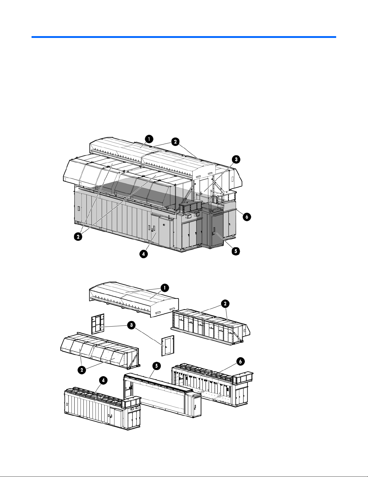
The HP POD 240e NA documentation frequently refers to these specific components of the HP POD 240e
NA.
The following figure shows the assembled HP POD 240e NA structural components.
The following figure shows the exploded view of the individual sections of the HP POD 240e NA.
Component identification 8
Page 9
Item Component Description
1
2
3
4
5
6
Canopy The canopy has two 6.10 m (20 ft) parts that are installed on top of the HP
POD 240e NA.
Adiabatic units and
Each of the four cradles contain three Adiabatic units.
cradles
AHU service area end
The HP POD 240e offers AHU service access in these two locations.
walls
IT section A (primary
structure)
The IT section A (primary structure) contains the ECS. Conditioned air passes
through the IT section A and IT section B structures to force cool air through the
IT equipment.
Hot aisle The hot aisle structure is a separate space where hot exhaust air from the
servers can be expelled out of the structure or recirculated. The HP POD 240e
isolates the IT sections from the hot aisle for efficiency.
IT section B (secondary
structure)
IMPORTANT: You must consult with the AHJ to determine the egress requirements for the hot-aisle
The IT section B (secondary structure) is similar to the IT section A (primary
structure), but IT section B does not contain the ECS.
service area that you must provide. Requirements might include landings and stairs to be installed
at both ends of the hot aisle service area for emergency egress.
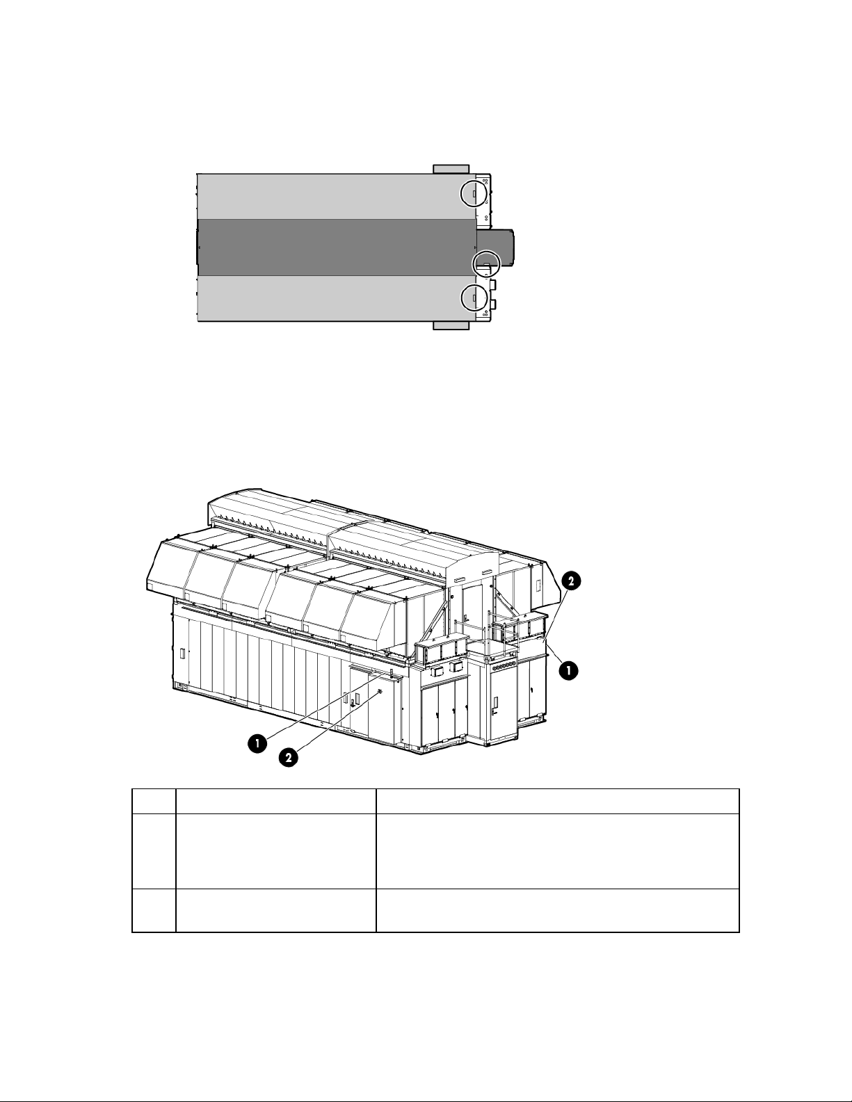
Parts and part number identification
Review all of the contents to identify the following for each component:
Regulatory model number
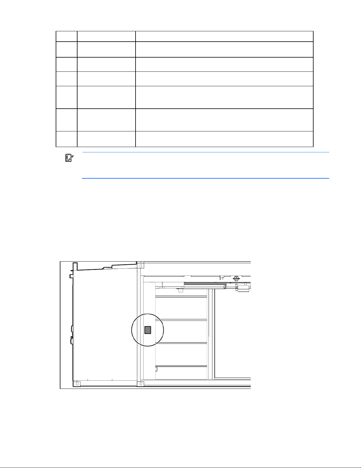
The following figure shows the location of the regulatory model number and the POD solution serial numbers
on the inside of each IT section, adjacent to the bump out.
Interior side view shown
CSC Safety Approval placard
Component identification 9
Page 10
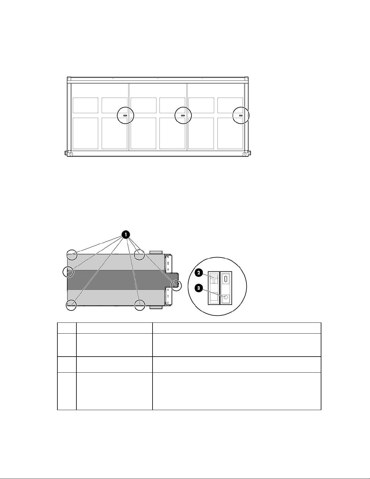
Each HP POD 240e NA Adiabatic AHU has a CSC Safety Approval placard that includes model number,
serial number, and proof load. Each AHU has a different serial number. The following figure shows the CSC
Safety Approval placard locations.
Side view single AHU cradle shown
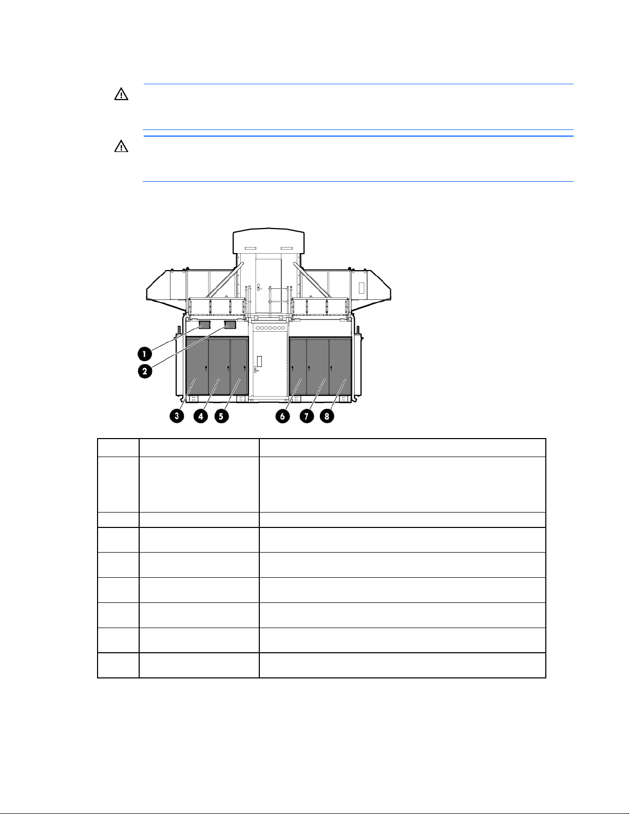
Life safety component identification
Internal life safety components
Top view shown
Item Component Description
1
2
3
Emergency switch locations There are six emergency switch boxes, one by each personnel access
door throughout the HP POD 240e NA. Each emergency switch box
includes items (2) and (3).
Fire alarm manual pull Enables manual initiation of the fire system, which includes the
activation of the interior and exterior fire strobe lights.
EPO button Disconnects the HP POD 240e NA from main power feeds and
activates the red EPO indicator light on the outside of the HP POD 240e
NA.
To reset the EPO button, switch the EPO to the Active position. Failure to
do so prevents the HP POD 240e NA from being able to restart.
Exit sign locations
Component identification 10
Page 11
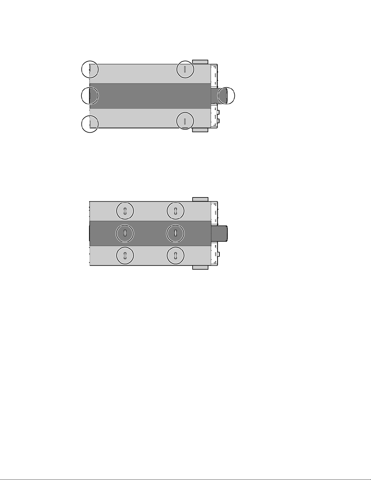
Top view shown
Internal emergency lighting
Top view shown
Internal emergency status indicators
Component identification 11
Page 12
Top view shown
•
•
•
There is one fire strobe light in each aisle of the HP POD 240e NA. When illuminated, these lights indicate
a fire alarm condition within the HP POD 240e NA.
External emergency status indicators
Item Component Description
1
External EPO status indicator Indication of operating status:
White—Normal operating mode
Yellow—Bypass operating mode
Red—EPO shutdown mode
2
Fire strobe light Indicates a fire alarm condition within the HP POD 240e NA.
There is one fire strobe light on each side of the HP POD 240e NA.
Component identification 12
Page 13
requirements when opening or working inside areas of the HP POD 240e NA that are marked as
•
•
•
Electrical power component identification
WARNING: To avoid the risk of personal injury or loss of life, all personnel must comply with PPE
End view shown
hazardous voltage, per NFPA 70E in accordance with NEC (NA) and IEC (EMEA and APJ).
WARNING: To avoid the risk of personal injury or loss of life, all personnel must comply with
electrical warning labels when operating and maintaining the electrical panels and systems of the
HP POD 240e NA.
Item Component Description
1
Demarcation box Customer communication connection point:
ECS
Access control
Phone
2
3
4
5
6
7
8
Fire box Connection location for fire emergency and VESDAnet signals
415/240V 3-phase, wye,
A feed power for IT Section A electrical busways and house power
4-wire
415/240V 3-phase, wye,
B feed power for IT Section A electrical busways and house power
4-wire
Mechanical power feed
A and B feed power for the IT Section A AHU
cabinet
Mechanical power feed
A and B feed power for the IT Section B AHU
cabinet
415/240V 3-phase, wye,
B feed power for IT Section B electrical busways and house power
4-wire
415/240V 3-phase, wye,
A feed power for IT Section B electrical busways and house power
4-wire
Main breaker locations
Component identification 13
Page 14
End view shown
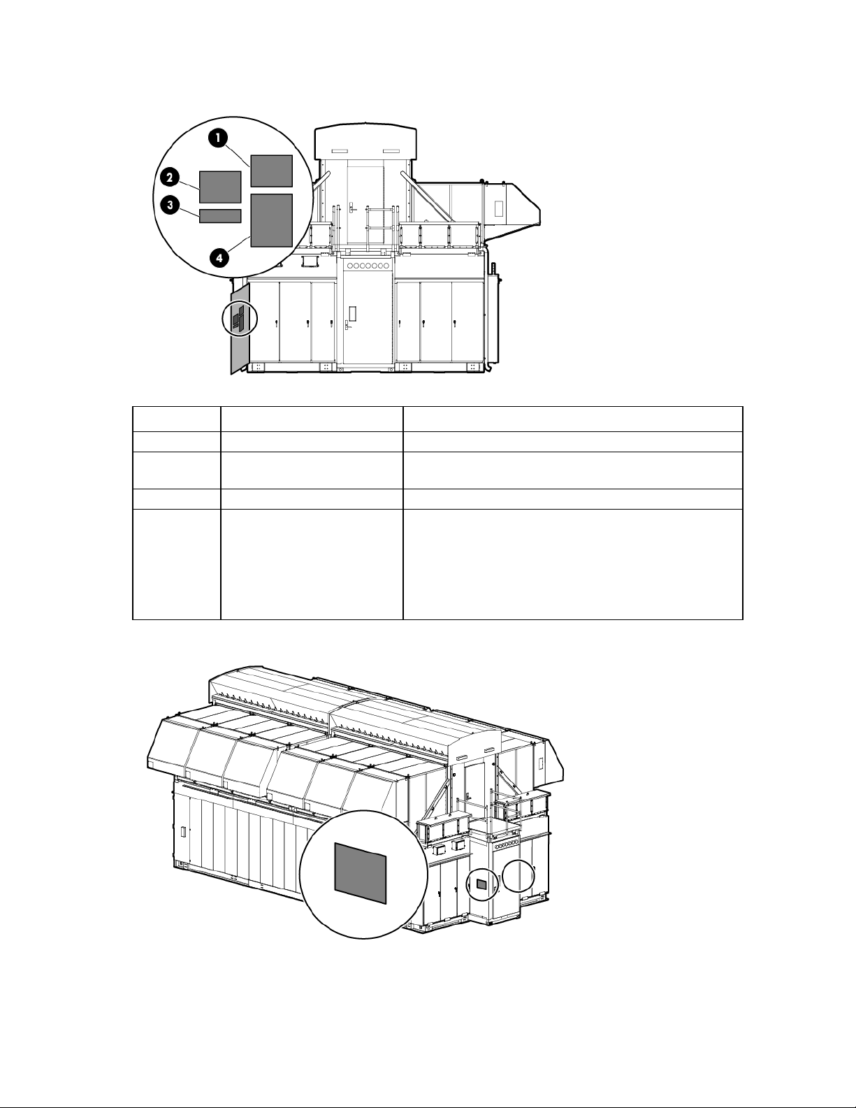
External safety labels
End view shown
Callout Electrical safety label Description
1
2
3
4
Danger sign Reminds you that the electrical panels must only be
accessed by authorized personnel.
Disconnect label Provides the disconnect order for all of the electrical
panels.
Caution Cautions you about isolating power from the product.
Arc flash warning Reminds you of arc flash danger and required PPE.
The customer must complete an arc flash assessment of the HP POD 240e NA and the associated electrical
supply system for such things as operation and maintenance.
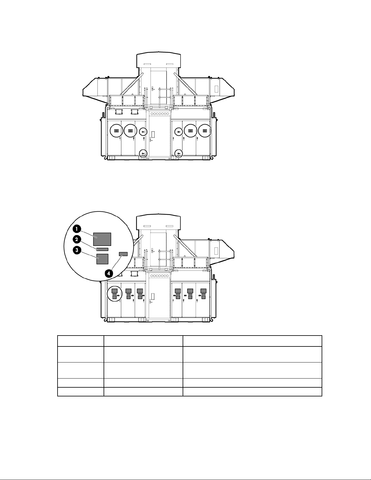
Internal panel labels
Component identification 14
Page 15
End view shown
•
•
•
•
•
Callout Electrical safety label Description
1
2
3
4
Input power Lists the input power information
Panel schedule/circuit breaker
table
Fuse type table Lists all fuse types and sizes
Wire color code 415/240V wye color codes
Lists the layout and designation for all circuit breakers on the
panel
Purple/Brown
Purple/Orange
Purple/Yellow
Purple/White—Neutral
Green and yellow—Equipment ground
Electrical power disconnect map label location
Component identification 15
Page 16
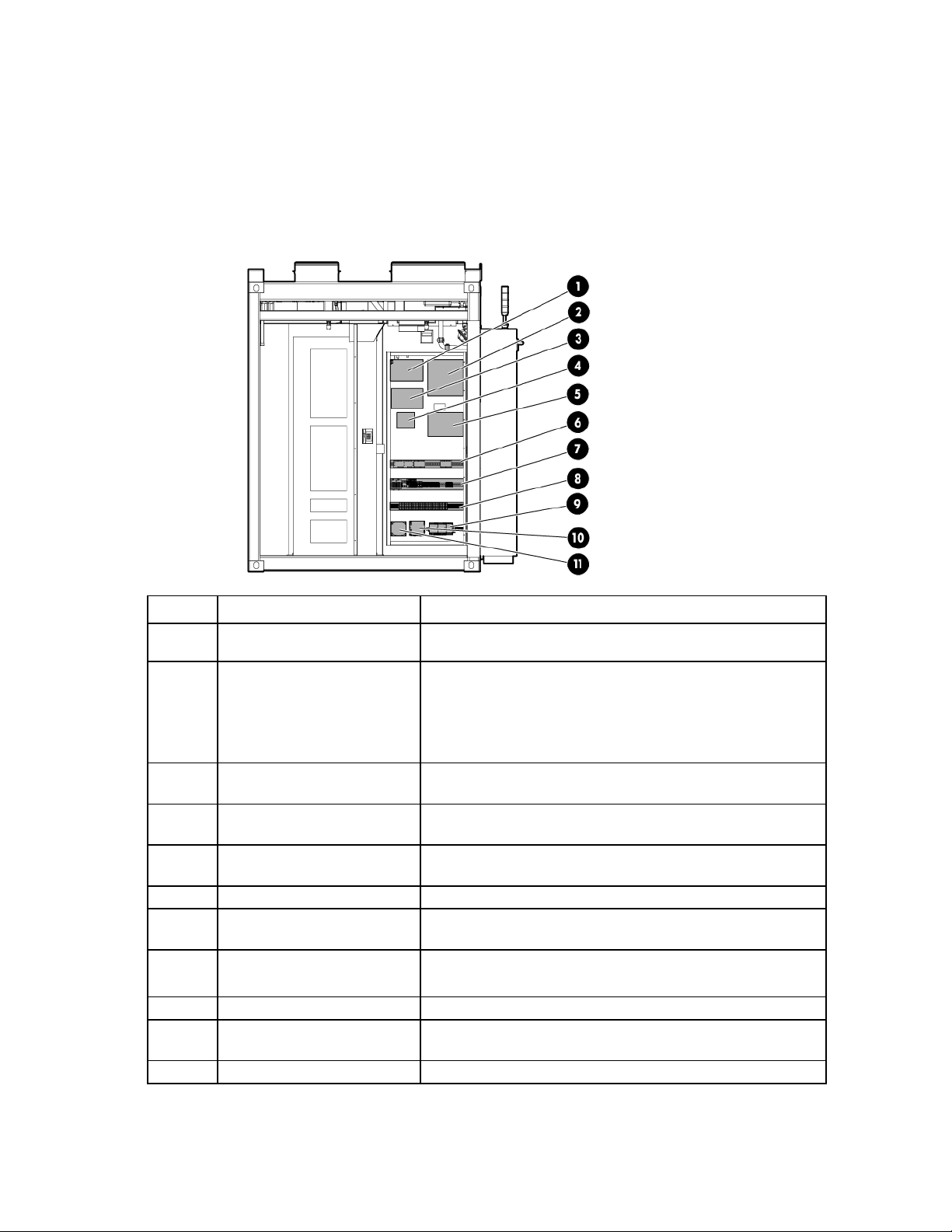
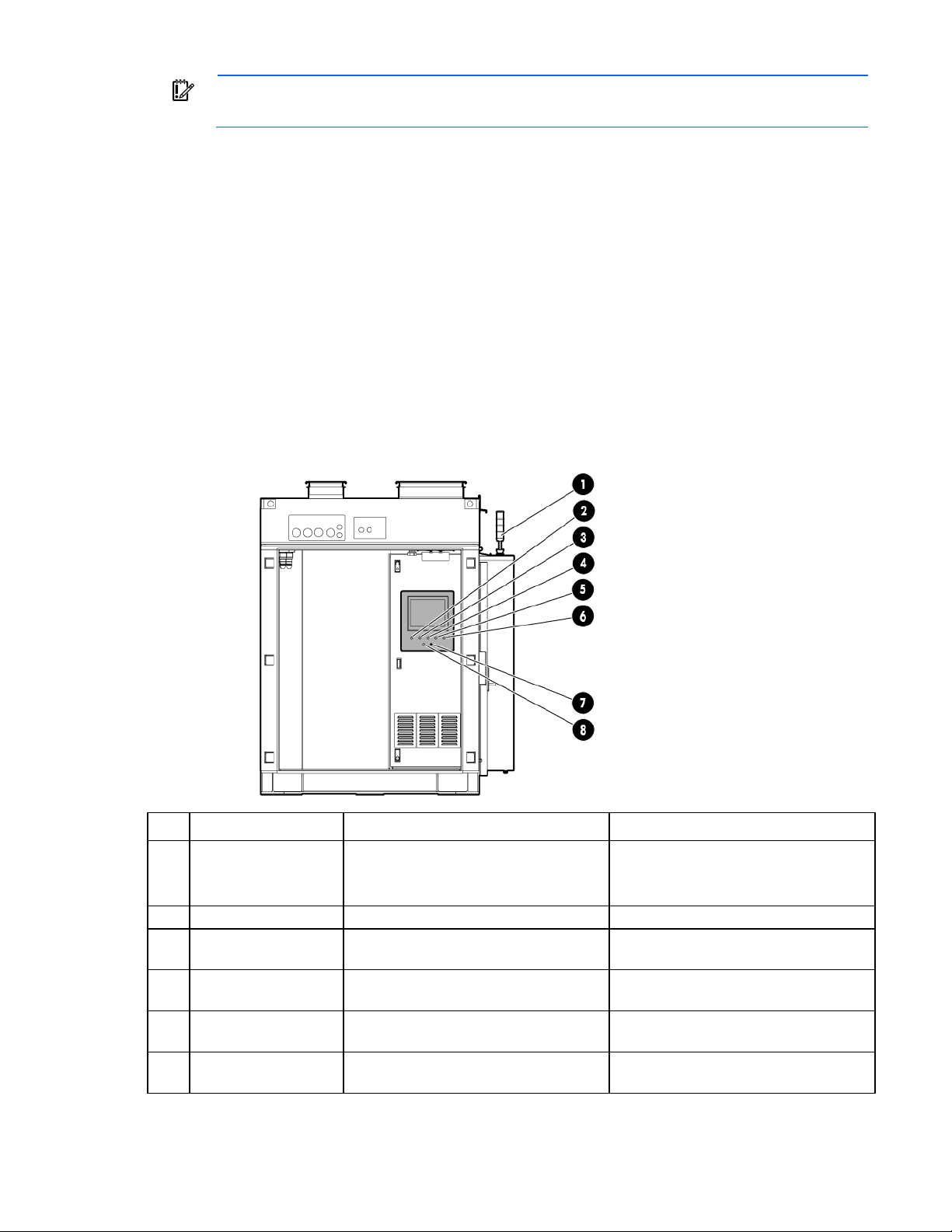
Control cabinet component identification
•
•
ECS modules and terminal
Used for ECS communication, I/O connections, and terminal block
All circuits in the control cabinet are labeled with the panel name and circuit breaker number.
Each IT section has one control cabinet that houses the various control components for that IT section.
IT section A control cabinet
The ECS and fire panel controls are located in the IT section A control cabinet.
Item Component Description
1
2
VESDA air sampling smoke
detection unit
Fire alarm control panel
An early warning laser scan smoke detection unit
Controls all fire systems within the HP POD 240e NA,
including the smoke detection system and manual fire pulls
Includes a battery backup system to provide backup power to
the fire system in the event of power loss to the HP POD 240e
NA
3
4
5
6
7
8
9
10
11
UPS Provides backup power to the IT section A VESDA in the event of
power loss to the HP POD 240e NA
Access control module Controls and organizes information that is monitored by the HP
POD 240e NA access control components
Customer access control
junction box
ECS relays Relays for the ECS control
blocks
House power fuses and terminal
blocks
Power supply* Provides 24V DC power to the PLC, ECS, and LED lighting
UPS* Provides battery backup power to the PLC and ECS in the event of
240/120V transformer Provides house power to IT section A convenience outlets
Provides a location for the facility access control components and
connects the facility to the HP POD 240e NA
connections
Provide house power to the HP POD 240e NA convenience outlets
and lighting
power loss to the HP POD 240e NA
Component identification 16
Page 17
Item Component Description
NA
*These components are only installed in the IT section A control cabinet.
PLC* The computer located on the inside door of the control cabinet that
controls the ECS system
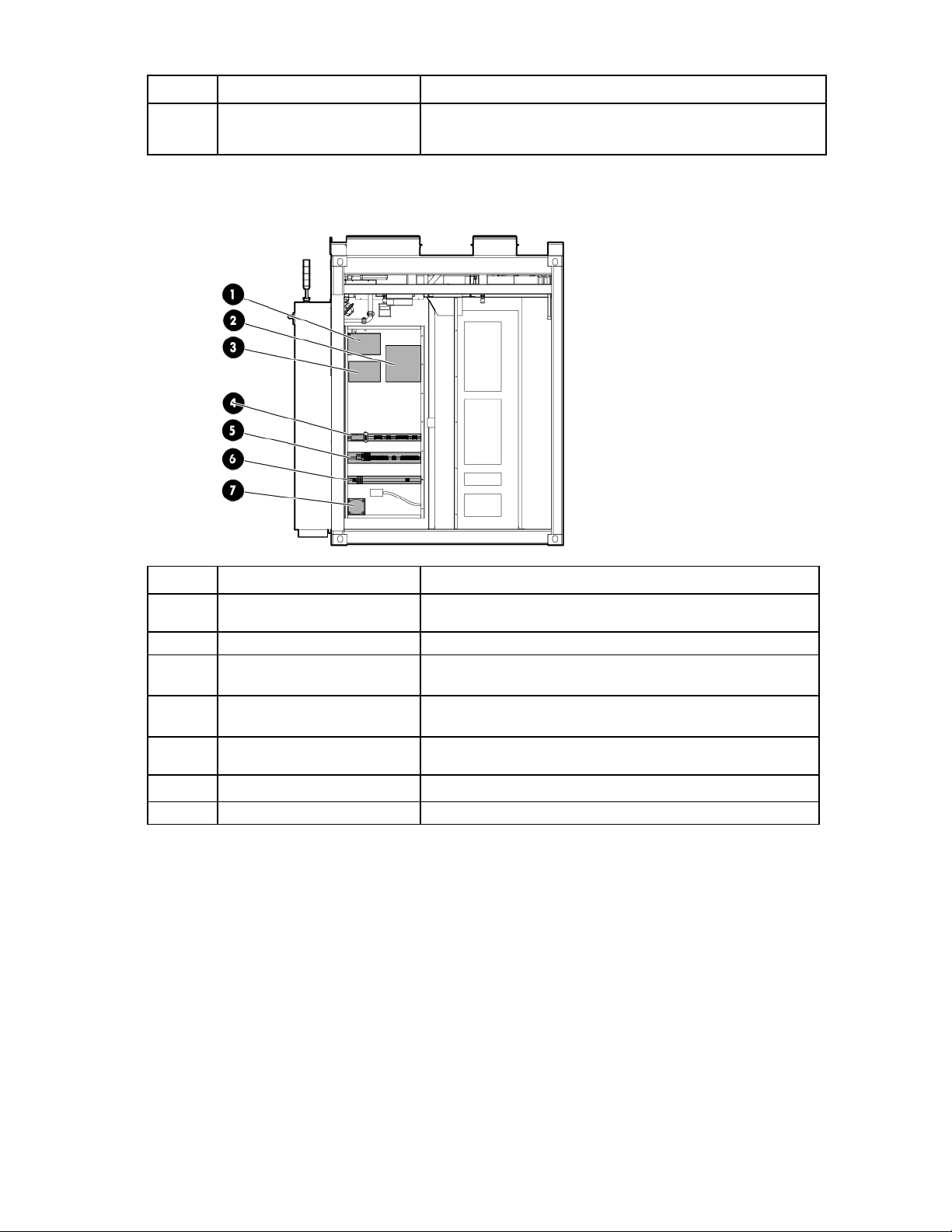
IT section B control cabinet
Item Component Description
1
2
3
4
5
6
7
VESDA air sampling smoke
detection unit
Fire system junction box Junction box to connect the IT section B fire system to IT section A
UPS Provides backup power to the IT section B VESDA in the event of
DIN rail with EPO modules Sends a signal to all of the connected EPO devices
DIN rail with terminals and ECS
communication modules
DIN rail with terminals and fuses Sends information from IT section B to the PLC in IT section A
240/120V transformer Provides house power to IT section B for convenience outlets
An early warning laser scan smoke detection unit
power loss to the HP POD 240e NA
For more information, see "EPO system (on page 19)."
Sends information from IT section B to the PLC in IT section A
For more information about the specific control components within the control cabinet, see the Operations
and Maintenance Manual for the HP Performance Optimized Datacenter 240e North America (Adiabatic).
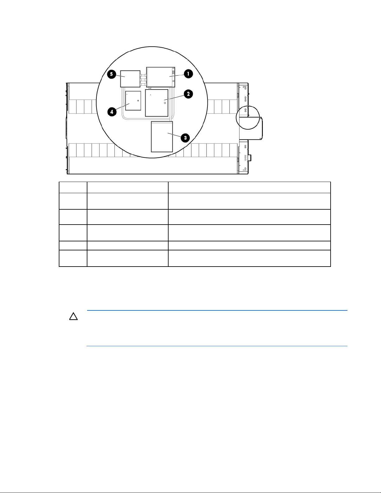
Security component identification
The security system components are located in the hot aisle porch.
Component identification 17
Page 18
Top view shown
Item Component Description
1
2
3
4
5
Racks
The HP POD 240e NA has 22 IT racks per IT section, for a total of 44 IT racks per HP POD 240e NA.
For more information about racks and network cabling, see the HP POD 240e NA Networking Guide.
Security panel and Mag lock
power supply
Security card access door
termination
Security card access battery
backup
Main security controller board Controls all security components
Cross connect for IT section A
and B doors
CAUTION: If any racks contain empty RU space, use the HP POD 240e NA filler panels to
Provides power for the security panel and the personnel access
door Mag locks
Controls card readers on the personnel access doors
Provides battery backup for the card readers on the personnel
access doors
Provides power and sends signals to the installed access control
components
maintain the efficiency of the HP POD 240e NA thermal system. Filler panels are available from
HP in 10-pack quantities (part number AQ682A) and 100-pack quantities (part number
AS993A).
Component identification 18
Page 19
Life safety systems
Life safety overview
The HP POD 240e NA has multiple life safety systems that work together to protect the HP POD 240e NA
equipment and personnel. The following life safety systems are included on the HP POD 240e NA:
• EPO system (on page 19)
• Fire detection system (on page 22)
• Emergency egress (on page 24)
• Facility connections to ECS ("Facility connections to the ECS" on page 35)
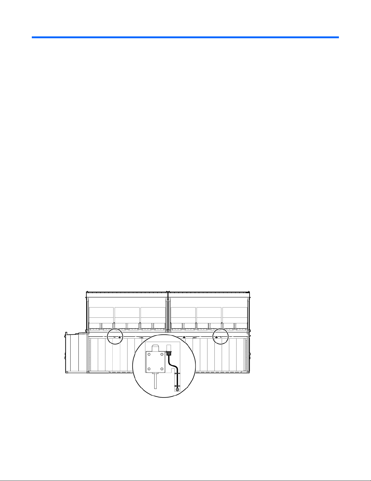
EPO system
If the HP POD 240e NA must be shut down during an emergency, the EPO system automatically powers off
the HP POD 240e NA, activates the EPO indicator on the ECS panel door, and changes the EPO status light
tree that is located on the POD exterior to red.
To be sure that all rack-mounted UPS devices are shut down during an EPO event, verify that each
rack-mounted UPS device is connected to the HP POD 240e NA EPO system.
The EPO system can be activated two ways:
• Excessive high temperature in the hot aisle—The HP POD 240e NA includes two thermisters. If both
thermisters reach 60°C (140°F), an EPO shutdown is triggered automatically.
Side view
• Manual initiation—To manually trigger an EPO shutdown, press any of the EPO buttons. There are EPO
buttons located next to the personnel access doors in the POD.
For the location of EPO buttons, see "Life safety component identification (on page 10)."
Life safety systems 19
Page 20
IMPORTANT: The EPO system must be reset before you can power up and restart the HP POD
•
•
•
240e NA.
To reset the EPO system:
1. Determine and correct the reason for EPO system initiation.
2. If the EPO was triggered manually, the EPO button that was pushed must be reset by rotating the button
as indicated.
3. Verify the key control for the EPO mode is in the Armed position.
4. Press and release the white EPO reset button.
ECS touchscreen and EPO indicators
The ECS touchscreen and EPO indicators are located on the IT section A control panel door.
The touchscreen enables easy configuration of environmental parameters and access data, and also
monitors environmental, life safety, and security conditions within the HP POD 240e NA.
The EPO indicators provide the EPO status and enable the EPO system mode to be adjusted.
Item Component Indicator color Description
External EPO status
1
indicator
White—Normal operating mode
Yellow—Bypass operating mode
Indicates the operating status of the HP
POD 240e NA
Red—EPO shutdown mode
Power on White Indicates the EPO power status
2
EPO shutdown Red Indicates an EPO shutdown or alarm
3
EPO armed White Indicates the EPO system is armed and
4
EPO bypass mode Yellow Indicates the EPO is operating in bypass
5
EPO bypassed Green Indicates that the EPO functionality and
6
condition
operational
mode
shutdown is bypassed
Life safety systems 20
Page 21

Item Component Indicator color Description
•
•
•
EPO mode Key control The key control allows you to select the
7
EPO reset White button Select to reset the EPO system
8
EPO modes
The EPO system has three operating modes:
• Armed—The EPO system is armed and operational.
• Test—The EPO system is in test mode and will not power off the HP POD 240e NA in the events that
would normally trigger an EPO.
• Bypass—The EPO system is non-operational and will not power off the HP POD 240e NA in any events
that normally trigger an EPO.
For more information, see "ECS touchscreen and EPO indicators (on page 20)."
EPO mode:
Armed
Test
Bypass
The illuminated external EPO status indicator displays the current EPO mode.
• White—The EPO system is armed and operational.
• Red—There has been an EPO event and the HP POD 240e NA is shutdown.
• Yellow—The EPO system is operating in test mode.
EPO accidental activation
To help prevent accidentally pressing the EPO button and activating the EPO system, each EPO button is
covered with a clear Lexan cover.
Battery backup during an EPO event
The following components are equipped with a UPS to help be sure that service is not interrupted during a
loss of power to the HP POD 240e NA:
• Environmental control system (on page 34)
• VESDA air sampling smoke detection system (on page 22)
• Fire detection system (on page 22)
• Lighting (on page 33)
IMPORTANT: All critical IT UPS devices with batteries that exceed 700VA must be connected to
the HP POD 240e NA EPO system, to be sure that the UPS batteries are disconnected during an
EPO event. For more information about connecting UPS devices to the EPO system, see the HP
Performance Optimized Datacenter 240e NA Maintenance and Service Guide.
Life safety systems 21
Page 22

Fire detection system
Each HP POD 240e NA is equipped with a fire alarm panel that is integrated with the fire detection system.
The fire system is designed as a stand-alone system, but the system can also interface with customer site fire
alarm systems. Customer site connections are the responsibility of the customer. Consult with HP for
connection locations.
The fire protection system includes:
• VESDA air sampling smoke detection system (on page 22)
• Manual fire pulls (on page 22)
• Fire alarm panel (on page 23)
• Fire alarm indicators (on page 23)
VESDA air sampling smoke detection system
CAUTION: Excess dust within the HP POD 240e NA can cause the VESDA smoke detector to
The VESDA system features a single zone laser scan early warning smoke detector to provide the earliest
warning of a potential fire.
The orange VESDA piping that runs throughout the HP POD 240e NA includes inlets for smoke sampling. The
VESDA uses a high-efficiency aspirator to continuously draw in air from the HP POD 240e NA and circulate
the air through a dual-stage filter:
• Stage 1—A filter removes dust and dirt from the air sample.
• Stage 2—An ultra-fine filter removes remaining contaminants in the air sample.
After the air passes through the dual-stage filter, it enters a calibrated detection chamber where a laser scans
the air sample for the presence of smoke. The VESDA system cycles through two levels if smoke is detected:
• Level 1—Smoke concentration reaches the first setpoint, and the VESDA system sends an alarm signal
• Level 2—Smoke concentration reaches the second setpoint, and the VESDA system indicates that a fire
trigger a fire alarm.
indicating that a fire might exist.
exists in the HP POD 240e NA.
IMPORTANT: The VESDA filter must be changed regularly to be sure that smoke detection
readings are accurate. For more information about changing the VESDA filters, see the HP
Performance Optimized Datacenter 240e NA Maintenance and Service Guide.
Manual fire pulls
The HP POD 240e NA has six fire pulls; two in each aisle. They are located in the life safety switch cabinet
next to each personnel door of the HP POD 240e NA.
Manually activating a fire pull does the following:
• Triggers a fire alarm
• Activates the fire alarm system horn and strobe lights
Life safety systems 22
Page 23

Fire alarm panel
The fire alarm panel is located in the control cabinet in IT section A and receives signals from the VESDA or
manual fire pulls if an alarm condition exists. If an alarm condition does exist, the fire alarm panel activates
the fire alarm indicators and sends a signal to the site fire alarm system, if installed.
The fire alarm panel also has a battery backup system that provides backup power to the fire detection
system in the event of power loss to the HP POD 240e NA.
The control panel includes the following components:
• Alarm status LED
• Trouble status LED
• Input status LED
• Output status LED
• Acknowledge button
• Alarm Silence button
• System Reset button
Fire detection sequence of operations
There are two initiation sequences for the fire detection system, automatic (VESDA) initiation and manual
initiation. The fire strobe light is activated by either initiation sequence.
The fire alarm horn will sound in a temporal mode for any VESDA or manual fire pull initiation.
The fire system operator panel indicates which initiation sequence is active, using the indicator lights and a
panel alarm. These signals are also available to the site BMS system, if they are connected.
VESDA initiation
When smoke is detected, the VESDA fire detection system cycles through two levels, as described below.
• Level 1—Indicates the potential for a fire is present. The strobes illuminate and the horns sound.
• Level 2—Indicates that a fire exists. VESDA level 1 might have be reached; the strobes illuminate and
the horns sound.
Manual initiation
Manual initiation triggers the fire alarm, causes the fire strobe lights to illuminate, and sounds the horn.
Fire alarm indicators
Upon activation of a fire alarm within the HP POD 240e NA, the following alarms alert personnel:
• Strobe lights
o Internal—The HP POD 240e NA has three fire strobe lights; one in each aisle.
o External—The HP POD 240e NA has two fire strobe lights; one on each side.
• Audible horn—The HP POD 240e NA has three horns; located with the three internal strobe lights
• Alarm within the ECS
Life safety systems 23
Page 24

Emergency egress
The HP POD 240e NA includes the following features for life safety egress on all access doors:
• Exit signs
• Panic bar
• Door strikes
o Standard hardware—Door strikes
o Optional hardware—Electric door strikes
Each personnel door includes a standard panic bar to be sure there is a safe exit. Any of the optional egress
hardware that is included in the HP POD 240e NA (including electric panic bar, electric strikes, and
magnetic locks) are tied to the fire alarm to enable uninhibited egress in the event of an emergency.
Life safety systems 24
Page 25

Power, electrical, and controls
requirements when opening or working inside areas of the HP POD 240e NA that are marked as
Site electrical system
To be sure that the POD solution is completely and safely integrated with your facility, HP requires that you
complete the following actions for the installed electrical system prior to the installation of the HP POD
solution:
• Short circuit analysis
• Arc flash study
• Circuit breaker coordination study
These actions must be performed for all associated parts of the electrical power train. The majority of the
details and factors that are required to complete these studies are associated with the existing installed
facility infrastructure.
CAUTION: Failure to complete these studies can cause serious issues with the electrical
integration of the POD into your electrical system.
Power safety
WARNING: To avoid the risk of personal injury or loss of life, all personnel must comply with PPE
Grounding and bonding
The HP POD 240e NA must be properly earthed to be sure that a common return path for electric current
exists, limit the build-up of static electricity, and absorb an unlimited amount of current without changing its
potential. To properly ground the HP POD 240e NA to the earth, you must connect the POD to building steel,
a ground rod, or a properly installed ground well that is connected to a building’s grounding system. The
grounding electrode conductor connection point is located on the cold aisle side adjacent to the power
cabinet.
Grounding
A certified electrician must test and verify the HP POD 240e NA is properly grounded.
hazardous voltage, per NFPA 70E in accordance with NEC (NA) and IEC (EMEA and APJ).
WARNING: To avoid the risk of personal injury or electric shock, the HP POD 240e NA must be
properly earthed (grounded), and each of the individual sections must be bonded together per
NFPA 70 in accordance with NEC (NA) and IEC (EMEA and APJ).
The HP POD 240e NA includes the following types of grounding.
Earth ground
Power, electrical, and controls 25
Page 26
Side view shown
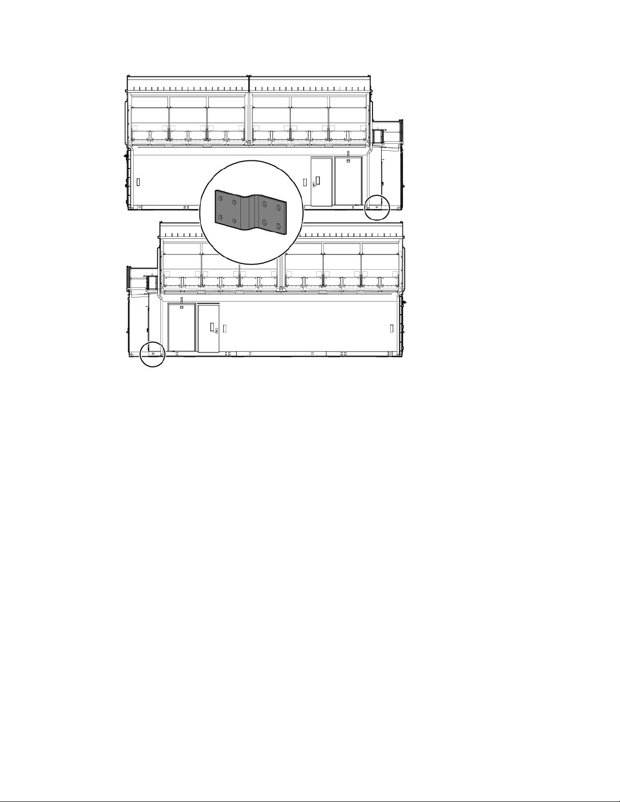
Bonding
All structural sections of the HP POD 240e NA are bonded by connecting all metallic, non-current carrying
items throughout the HP POD 240e NA to protect from electric shock. If all steel-to-steel areas are bonded to
one another, each object then has the same electrical potential which ultimately dissipates any high voltage
or shock across the entire HP POD 240e NA, minimizing any effects from a lightning strike, per NFPA 70 in
accordance with NEC (NA) and IEC (EMEA and APJ).
Lightning protection
The HP POD 240e NA structure and internal components are all bonded together. A common grounding
electrode conductor connection point is provided. Proper bonding and grounding of the HP POD 240e NA
minimizes the effects of a lightning strike. A surge protection device is provided on the HP POD 240e NA
input connection to protect the HP POD 240e NA electrical system from voltage transients. If your site is in an
area that is subject to frequent lightning strikes, the HP POD 240e NA must be protected in accordance with
NFPA 70 (NA) and IEC (EMEA and APJ). HP recommends that you contact a certified lightning protection
consultant.
Capacities
Each HP POD 240e NA is unique and the specific power and cooling capacities vary for each POD that uses
Adiabatic cooling. For specific capacity information, see your HP Performance Optimized Datacenter 240e
NA Customized Supplement.
Power, electrical, and controls 26
Page 27
A licensed electrician must connect the power according to all local and national
requirements when opening or working inside areas of the HP POD 240e NA that are marked as
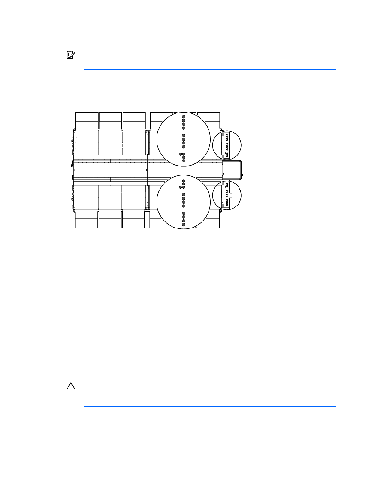
Power feeders
IMPORTANT:
Twenty-four power feeder couplings, twelve per IT section, provide the entrance for power to the HP POD
240e NA. The power feeders route into the top of each electrical panel on the end of the HP POD 240e NA.
Top view shown
electrical codes, and must comply with manufacturer specifications.
The twenty-four power couplings are identified as either main power couplings or Adiabatic mechanical
power couplings.
Main power couplings
• Each of the four main power panels contains four power feeder couplings, for a total of sixteen main
power couplings.
• Each main power coupling has a 10.16 cm (4 in) diameter.
Adiabatic mechanical power couplings
• Each of the two Adiabatic power panels contains four power feeder couplings, for a total of eight
Adiabatic mechanical power couplings.
• Each Adiabatic mechanical power coupling has a 7.62 cm (3 in) diameter.
Power feeders are sized in accordance with NEC and IEC regulations.
Electrical panel labels
WARNING: To avoid the risk of personal injury or loss of life, all personnel must comply with PPE
hazardous voltage, per NFPA 70E in accordance with NEC (NA) and IEC (EMEA and APJ).
Power, electrical, and controls 27
Page 28

WARNING: To avoid the risk of personal injury or loss of life, all personnel must comply with
electrical warning labels when operating and maintaining the electrical panels and systems of the
HP POD 240e NA.
For the external electrical power component locations, see "Electrical power component identification (on
page 13)."
Power distribution: electrical busway system
Each IT section of the HP POD 240e NA is protected by an electrical circuit breaker panel located on the end
of the HP POD 240e NA.
End view shown
The following specifications are for each IT section electrical circuit breaker panel.
Feature Specification
Number of busways
Frequency
Amps (per busway)
Voltage (per busway)
Grounding
Busway conductors
8
60 Hz
200A
415V, wye
Copper
3-phase + neutral + equipment ground
Power distribution: Adiabatic system
The Adiabatic units are powered and protected by an electrical circuit breaker panel located on the end of
the HP POD 240e NA. Within each AHU electrical cabinet, there are two panels that provide power to the
Adiabatic units.
Power, electrical, and controls 28
Page 29

End view shown
•
•
•
Feature Specification
Frequency
Amps
Voltage
Grounding
Feeder conductors
Panel schedules
The panel schedule for each electrical panel is permanently affixed to the inside cabinet door of each
electrical panel.
Wire color code
IMPORTANT: The use of UL-approved colored tape over another color of wire is only acceptable
120 Volt Wiring System—Power required for the transformer in control cabinets
Wire color Description
on wire sizes #2 and larger.
60 Hz
125A
415V, wye
Copper
3-phase + equipment ground
Black
White
Green or green and
yellow
Single-phase current carrying conductor
Neutral
Equipment grounding conductor
Bonding conductor
Earth ground
415 Volt Wiring System—Power required for electrical busway feeders
Wire color Description
Brown and violet
A Phase
Power, electrical, and controls 29
Page 30
Wire color Description
•
•
•
Orange and violet
Yellow and violet
White and violet
Green or green and
yellow
B Phase
C Phase
Neutral
Equipment grounding conductor
Bonding conductor
Earth ground
Electrical busways
The electrical busway is a modular, overhead electrical distribution system that supplies power to the HP POD
240e NA IT loads. The HP POD 240e NA has a total of sixteen busways, eight per IT section. Each busway
can support 200 amps.
Top view shown
The HP POD 240e NA electrical busways can be configured for either non-redundant power or redundant
power. The HP POD 240e NA can be installed as a single source 1N load by providing all required feeders
from one common power sources and from common switchboards and transformers. A fully redundant 2N
installation is configured by feeding the parallel power paths from independent power sources,
switchboards, and transformers.
Power, electrical, and controls 30
Page 31
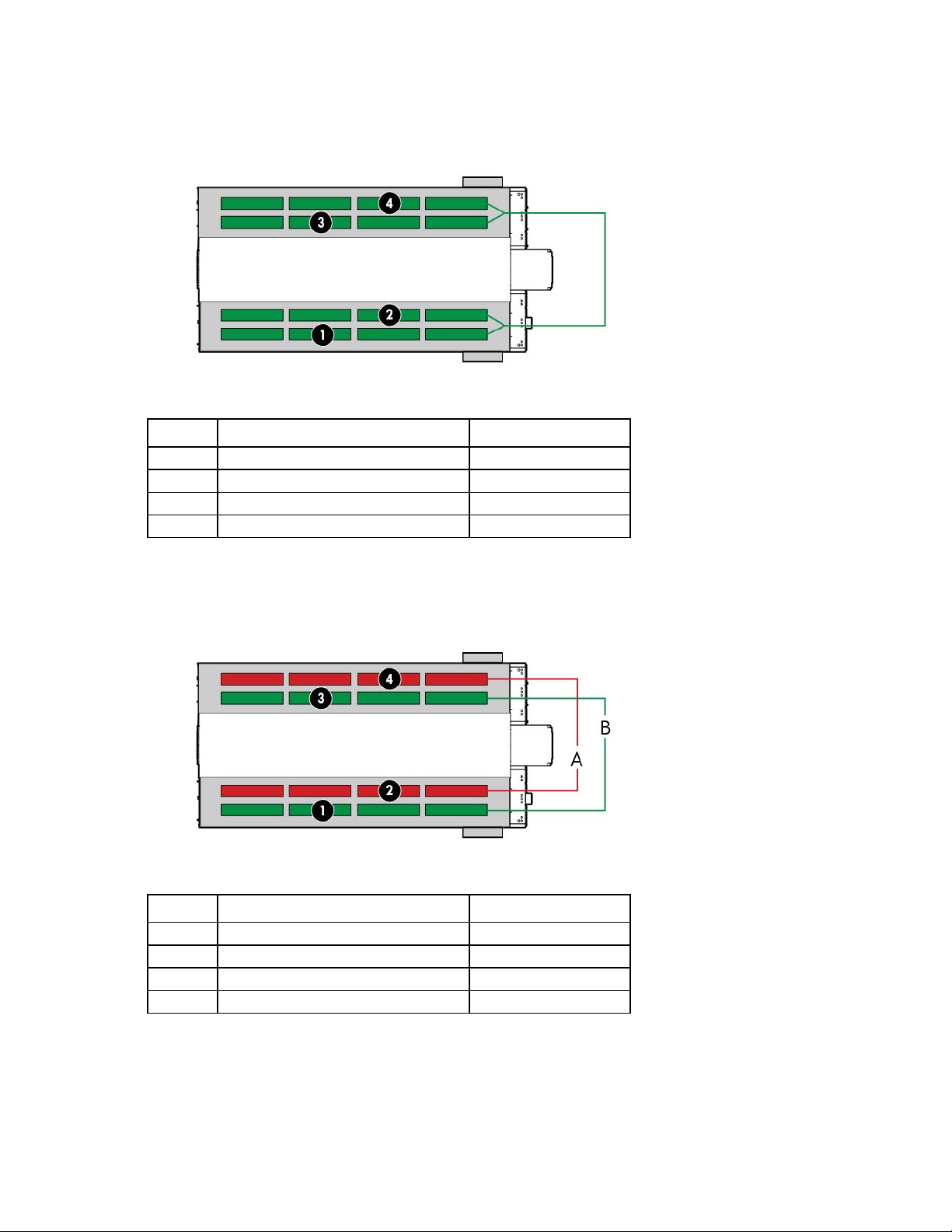
• Non-redundant power installation (1N load)—All four main input connections are powered from the
same power source.
Callout Component Power source
1
2
3
4
IT section A, Busway #1 Power source #1
IT section A, Busway #2 Power source #1
IT section B, Busway #1 Power source #1
IT section B, Busway #2 Power source #1
• Redundant power installation (2N load)—Each main input connection to the HP POD 240e NA is
powered from parallel power paths from independent power feeds.
Callout Component Power source
1
2
3
4
IT section A, Busway #1 Power source #1
IT section A, Busway #2 Power source #2
IT section B, Busway #1 Power source #1
IT section B, Busway #2 Power source #2
Power, electrical, and controls 31
Page 32

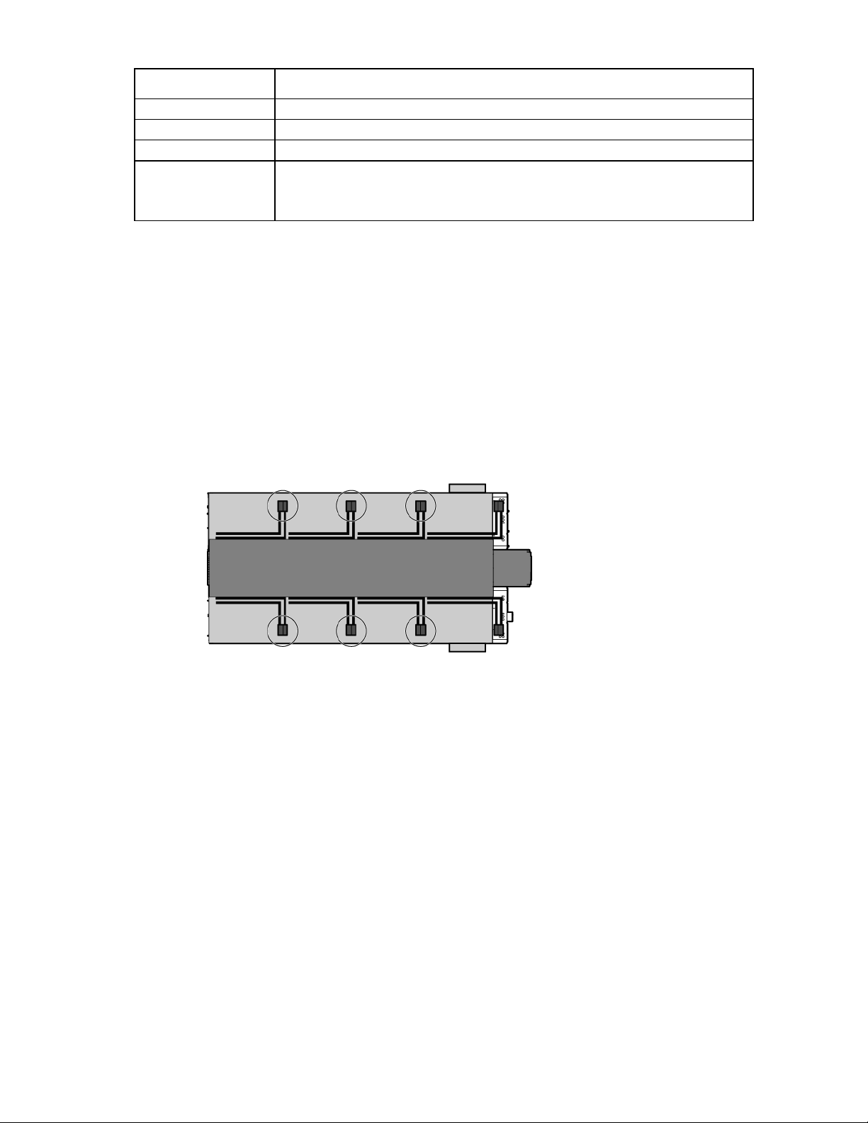
Drop boxes
The internal electrical busways provide a location to connect each of the drop boxes, which then power the
PDUs. For each IT section, stagger the drop boxes on the electrical busways by connecting one drop box to
busway #1 and connecting the next drop box to busway #2. A staggered configuration allows for load
balancing with the rack equipment and is necessary to create redundancy.
Side view shown
Disabling power
• To disable power to a single PDU, open the drop box breaker feeding that PDU and disconnect the PDU
from the drop box.
• To disable power to a single rack, open the corresponding breakers on the drop boxes feeding each of
the PDUs installed in that rack.
• To disable power to a single electrical busway, open the appropriate breaker for that busway on the
corresponding electrical busway panel outside of the HP POD 240e NA.
• To disable power to all racks on the A-side busways, open each breaker for each busway on the
corresponding electrical panel outside of the HP POD 240e NA.
Rack power
Power is provided to each rack by PDUs and drop boxes. The PDUs are powered by the drop boxes attached
to each electrical busway. For more information about electrical busway drop boxes, see the HP
Performance Optimized Datacenter 240e NA Maintenance and Service Guide.
Feature Specification
Rack type
Max number of racks
Max U space per rack
Max U space per HP POD 240e NA
Total number of PDU's
HP POD 240e NA rack
44 (22 per IT section)
50U
2,200U
88 (2 per rack)
Power, electrical, and controls 32
Page 33

Feature Specification
Max power per PDU
Average capacity per rack
Peak capacity per rack
Voltage to rack
Rack configuration
Lighting
The HP POD 240e NA includes lighting in each section:
• IT section A—four LED lights and two emergency lights
• IT section B—four LED lights and two emergency lights
• Hot aisle—six LED lights and two emergency lights
• Service aisle—four fluorescent lights
A light switch is located at every personnel door. For more information about light switch locations, see "Life
safety component identification (on page 10)."
30 A = 17 kW; 60A = 34 kW
30 kW
69.12 kW
240V
Redundant/Non-redundant capabilities
The IT sections and the hot aisle LED lights are tied to battery backup power, so the emergency lights will
activate to keep the interior of the HP POD 240e NA illuminated during a power outage or emergency.
For more information about lighting, see the HP Performance Optimized Datacenter 240e NA Maintenance
and Service Guide.
Power, electrical, and controls 33
Page 34

Environmental control system
Environmental control system overview
The ECS is a stand-alone control system developed for the HP POD 240e NA. The ECS does not require
external connections with an external site system, BMS, public or private internet site, cloud, or wireless
system to control the POD operation properly.
The ECS is designed to use Modbus TCP/IP connections to retrieve a variety of data. These capabilities
connect to the stand alone ECS system to monitor the operating parameters of the POD at your expense. It is
your responsibility (or your representative's or agent's responsibility) to integrate this communication
capability into any existing BMS or monitoring system.
CAUTION: To be sure that alarm conditions can be identified and resolved, HP recommends that
you remotely monitor all alarm conditions. Failure to monitor the alarm conditions can cause
delays in appropriate action during an alarm condition.
Using the ECS
HP recommends connecting the HP POD 240e NA to your facility BMS and establishing communication
through the Ethernet cable connected to the external communications box. For more information, see
"Configuring the ECS (on page 38)."
The HP POD 240e NA ECS is a Microsoft Windows-based system.
The standard ECS protocol, Modbus TCP/IP, is a data communication protocol for building automation and
control networks. Connecting across different protocols might require additional engineering labor and
coordination between your in-house control manufacturer and HP. It is your responsibility to make the
connection between the HP POD 240e NA and a BMS system.
The ECS provides the following:
• A supported communication interface that can remotely monitor and control certain HP POD 240e NA
components.
• Immediate notification of all supported alarm messages.
By connecting your HP POD 240e NA to a BMS system, you can monitor the various parameters and alarms.
For more information, see "Navigating the ECS interface (on page 42)." The complete list of parameters and
alarms that can be monitored will be discussed with your facilities personnel.
IMPORTANT: If your site does not have a BMS, HP POD 240e NA ECS data can be sent to and
viewed from a set of IP addresses on a host computer. The ECS communicates through an Ethernet
cable connected to the demarcation box (on page 67).
Environmental control system 34
Page 35

Components of the ECS
The ECS system uses several of the POD components throughout the HP POD 240e NA to maintain the
proper environmental conditions required within the HP POD 240e NA. The following components monitor
and report information to the ECS:
• AHU
• Dampers and actuators
• Electrical system
• Exhaust fans
• Humidity sensors
• Pressure sensors
• Temperature sensors
Satellite control boxes
The satellite control boxes are used as connection points for communication from the environmental sensors
back to the ECS control panel. Each satellite control box is configured for a different purpose, depending on
the needs of the IT equipment communicating through it.
The HP POD 240e NA has six satellite control boxes.
Top view shown
Facility connections to the ECS
The ECS can connect to an established network using the RJ45 in the demarcation box (on page 67), or using
the cables that are hard-wired through the connection portals on either end of the HP POD 240e NA. The
system uses Modbus TCP/IP for communication.
Environmental control system 35
Page 36

Connecting to the ECS through the demarcation box
To connect the network to the ECS control panel, route an Ethernet cable to the appropriate RJ45 connector
inside the HP POD 240e NA demarcation box (on page 67).
End view shown
Connecting to the ECS through connection portals
To connect an established network to the ECS control panel of the HP POD 240e NA, bring an Ethernet cable
through the IT portals on either end of the HP POD 240e NA, route it through the cable tray, and then connect
it directly to the ECS panel.
Environmental control system 36
Page 37

Top view shown
Managing the ECS from the HP POD 240e NA
The ECS interface is viewed directly from the ECS screen on the IT section A control cabinet door. For more
information, see "ECS touchscreen and EPO indicators (on page 20)."
Environmental control system 37
Page 38

To access the ECS while inside the HP POD 240e NA you can use a notebook or other customer-provided
computer, and connect an Ethernet cable between the notebook and the designated ECS jack.
Configuring the ECS
To configure the ECS:
1. Connect a host computer to the ECS. For more information, see "Managing the ECS from the HP POD
240e NA (on page 37)."
2. Configure your computer network settings:
a. Select Start>Control Panel>Network Connections.
b. Double-click Local Area Connection.
c. Select Internet Protocol (TCP/IP).
Environmental control system 38
Page 39

d.
Click Properties.
e. Select Use the following IP address.
f. Enter the new IP address. Be sure to specify an IP address in the same network group as the ECS
controller. By default, the ECS controller uses 192.168.20.1. The IP address for your computer can
include any number in the subnet from 2 to 254.
Environmental control system 39
Page 40

g.
Click OK.
3. Click OK to save changes and close the TCP/IP Properties screen.
4. Click OK to close the Local Area Connections Properties screen.
Logging in remotely to the ECS
Before you can log in remotely, you must do the following:
• Add the PLC to a network
• Obtain a username and password
• Obtain the static IP address of the PLC. For more information, see "Locating the ECS IP address (on page
41)."
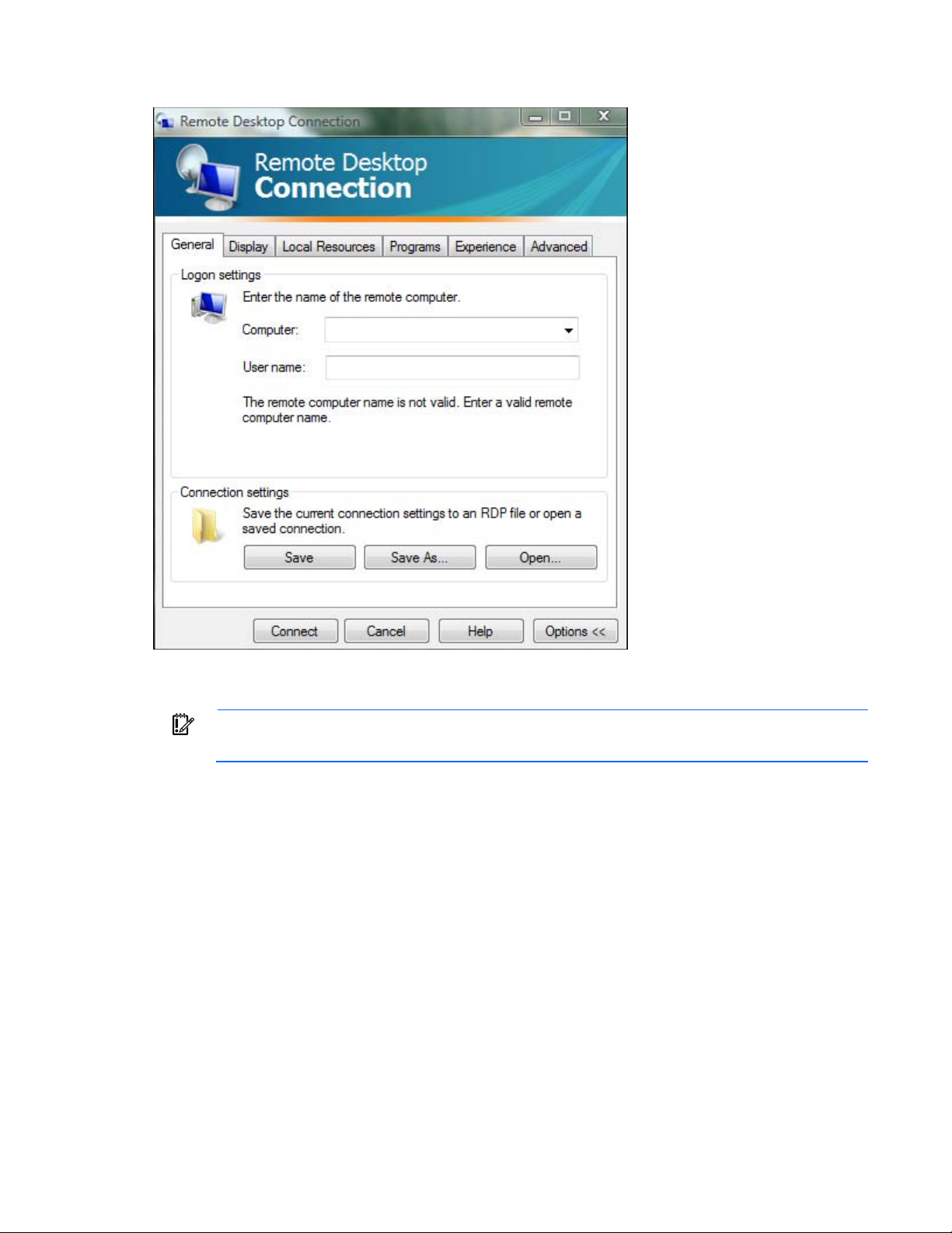
Use the remote desktop application to log in to the ECS remotely:
1. On the remote computer, select Start> All Programs> Accessories> Remote Desktop Connection.
The Remote Desktop window appears.
2. In the Computer field, enter the IP address for the PLC.
3. In the User name field, enter the user name.
IMPORTANT: When logging in to the Remote Desktop, the default user name is
Administrator and the default password is 1.
Environmental control system 40
Page 41
4.
The ECS has three NIC addresses: 10.10.10.1, 10.10.10.2, and an IP address
Click Connect.
Locating the ECS IP address
IMPORTANT:
that is set up by the customer for external communication.
The PLC must be connected to locate the IP address for each NIC. For more information, see "Managing the
ECS from the HP POD 240e NA (on page 37)."
To locate the ECS IP address:
1. Select Start>Run.
2. Enter ipconfig.
The IP address appears under adapter #3.
-or-
1. Select Start>Network and Sharing Center.
2. Right-click Local Area Network.
3. Click the Support tab.
The IP address appears.
Environmental control system 41
Page 42

Password protected
•
•
•
•
•
•
•
•
•
The ECS is password protected and has two levels of security:
• View—Allows read-only access to the ECS system. No password is required for this level of access to
the system.
• Customer—Allows you to configure alarm setpoints and Adiabatic control settings. The customer-level
password is required for this level of access to the system.
Navigating the ECS interface
The ECS interface provides information for environmental and security conditions You can monitor and
configure these conditions from the touchscreen LCD panel on the IT section A control cabinet.
To navigate to different screens in the system, select one of the menu options on the navigation toolbar at the
top of the screen.
Callout Icon name Description
1
2
Main menu toolbar Shows the main menu options available for
the password that is entered
System information Provides information on the following:
ECS version
Date
Time
3
4
Power Provides IT power and total power
information for A-side and B-side power feeds
Timer Allows you to monitor time for functions in the
system. To use the timer:
Click the timer to start it.
Click the timer again to reset it.
5
System overview Indicates the status of the AHU and ECS
systems:
Green—The systems are operating within
normal parameters
Amber—The systems are operating, but
has a notification or a low level warning
Red—The systems have a critical alarm
Gray—Communication to the AHU is lost
or the AHU is powered off
Navigates directly to the system detail screen
when you click the icon
Environmental control system 42
Page 43

Callout Icon name Description
6
Enter password Allows you to enter a password for greater
control in the ECS system
Logging in to the ECS touchscreen
To log in to the ECS touchscreen:
1. Click the lock icon at the top of the screen.
A keypad appears.
2. Enter your ECS password.
3. Click OK.
View
You can see the View menu when you have not entered a password and you have view-only access to the
ECS system. If you enter the customer-level password, the View menu allows you to configure alarm setpoints
within the ECS system.
The following screens are on the View menu:
• Top screen (on page 43)
• AD detail screen (on page 45)
• Charts screen (on page 47)
• Electrical Cabinets screen (on page 49)
• Controls Network screen (on page 50)
• Alarms screen (on page 51)
Top screen
• Stats screen (on page 52)
The Top screen opens immediately upon activating the ECS system through the LCD touchscreen display. The
screen displays an overview of all the ECS components and the status of each component.
IMPORTANT: The ECS parameters must only be set by qualified service personnel.
Environmental control system 43
Page 44

Indicates the hot aisle temperature at three different
The Top screen displays the following information for each IT section.
Information displayed Description
CA pressure
CA RH
CA combo temperature
Return temperature
HA pressure
Hot aisle temperature
Min and Max value sensor
number
Fan speed
Indicates the minimum, maximum, and average
pressure values for each IT section
Indicates the minimum, maximum, and average
relative humidity percentages from each IT section
Indicates the minimum, maximum, and average
temperature values for each IT section
Indicates the minimum, maximum, and average
return temperature values for each IT section
Indicates the minimum, maximum, and average
pressure values for the hot aisle
locations in the hot aisle.
Indicates the specific sensor that is reading the
minimum and maximum value for each statistic
Indicates the exhaust fan speed percentage
Environmental control system 44
Page 45

Information displayed Description
•
•
•
•
•
•
•
•
•
•
•
•
•
•
•
AD detail
Indicates detailed information for each Adiabatic
unit:
Hot aisle air
Return damper
Isolation damper
Water usage
Fan speed
Cold aisle air
Bypass damper
Outdoor damper
Outdoor air
ECS cabinet
Indicates the status of the ECS system and displays
the following alarm indicators:
EPO
Breaker
Power source
UPS
Door open
VESDA
The ECS component icon colors indicate the component status:
• Green—No alarm conditions exist and the component is operating within normal parameters.
• Amber—A warning alarm condition or notification for that component exists.
• Red—A critical alarm condition for that component exists.
• Gray—A loss of communication for that component exists or an AHU is powered off.
For more information about alarm conditions, see "Alarms screen (on page 51)."
To navigate to another screen, select one of the menu options on the navigation toolbar at the top of the
screen. For more information, see "Navigating the ECS interface (on page 42)."
AD detail screen
The AD detail screen displays detailed information for the Adiabatic unit selected. The Adiabatic unit number
appears at the top of the screen.
IMPORTANT: The ECS parameters must only be set by qualified service personnel.
Environmental control system 45
Page 46

Indicates the temperature reading from the hot
Indicates the dew point temperature from the wall
The AD detail screen displays the following minimum and maximum alarm setpoint ranges that you can
configure:
Setpoint displayed Description
HA return temperature
HA static pressure
CA wall temperature
CA temperature combo
CA relative humidity
CA dew point
CA static pressure
CA discharge temperature
aisle
Indicates the pressure value reading from the hot
aisle in relation to the external ambient
temperature
Indicates the temperature from the wall sensor
located in the IT sections
Indicates the average temperature from the wall
sensor and discharge temperature sensor
Indicates the relative humidity percentage from the
wall sensor
sensor
Indicates the pressure value reading from the IT
sections in relation to the external ambient
pressure
Indicates the discharge air temperature
The AD detail screen displays the following operational parameters for each AHU:
Environmental control system 46
Page 47

Operation displayed Description
Isolation damper
Water PID
Return damper
Bypass damper
Cold aisle fan
Outdoor damper
OA temperature
OA relative humidity
OA dew point
The AD detail screen displays the following alarm conditions:
Indicates the position of the isolation damper,
100% means the damper is open
Indicates the percentage of full flow water usage
Indicates the position of the return damper, 100%
means the damper is open
Indicates the position of the bypass damper,
100% means the damper is open
Indicates the speed of the cold aisle fan
Indicates the position of the return damper, 100%
means the damper is open
Indicates the OA temperature
Indicates the OA relative humidity
Indicates the OA dew point temperature
Alarm displayed Description
Filter
Fire/smoke
Hi water warning
Hi-Hi water critical
Heater over temperature
AC power failure
CA temperature compare
Winterize
Indicates that a filter needs to be changed
Indicates fire or smoke is detected
Indicates water in the Adiabatic drain pan
Indicates excessive water in the Adiabatic drain
pan
Indicates the AHU heater temperature is too high
Indicates the AHU power is in failure
Indicates the AHU discharge temperature is in
range of the other AHUs in the IT section
Indicates the Adiabatic units are operating in
Winterize mode
If an alarm condition exists for the Adiabatic unit, the parameter that is out of range will turn amber or red,
based on the severity of the alarm condition. For more information about alarm conditions, see "Alarms
screen (on page 51)".
To view the details of another Adiabatic unit, click the PREV/NEXT buttons on the top of the screen. These
buttons allow you to scroll numerically through all of the Adiabatic units.
Charts screen
The Charts screen displays the following information:
• Psychrometric chart (on page 48)—Displays recommended and operational ranges for the HP POD
240e NA.
• Readings chart (on page 48)—Displays static pressure, temperature, fan speed, water valve, or
damper readings.
Environmental control system 47
Page 48

• Alarms chart (on page 49)—Displays active critical and warning alarms.
Displays the minimum operating envelope that
Displays the configured operating envelopes for IT
Psychrometric chart
The Charts screen displays the range of the POD within psychrometric operating envelopes. The following
psychometric operating envelops are available.
Operating envelope Description
ASHRAE recommended
ASHRAE allowable
HP IT allowable
A/B side envelope
A/B side units
A/B side averages
Displays the recommended ASHRAE operating
envelope
ASHRAE recommends
Displays the recommended HP IT operating envelope
section A and IT section B Adiabatic units
Plots the current combination temperature, return air
temperature, and outdoor air temperature on the
psychrometric chart
Plots the IT section average combination temperature,
return air temperature, and outdoor air temperature
on the psychrometric chart
Readings chart
The readings chart at the bottom of the Charts screen displays the following information:
Environmental control system 48
Page 49

Information displayed Description
Static pressure
Temps
Fan speed
Water valve
Dampers
Indicates the cold and hot aisle static pressure
readings for each Adiabatic in relation to the
external ambient pressure
Indicates the cold and hot aisle temperature
readings for each Adiabatic unit
Indicates the fan speed for each Adiabatic unit
Indicates the water valve percentage for each
Adiabatic unit
Indicates the damper position for each Adiabatic
unit
To change the charts that display at the bottom of the screen:
1. Click a chart to bring up the chart menu.
2. Select the information that you want to view.
Alarms chart
The alarms chart displays critical and warning alarms that are active in the system. For more information, see
"Alarms screen (on page 51)."
Electrical Cabinets screen
The Electrical Cabinets screen displays detailed power meter information that is monitored from the HP POD
240e NA power input. This screen displays the voltage and current average for all 3-phase electrical feeds.
The apparent and real power values are the sum of all 3-phase electrical feeds. The values shown on this
screen are included in the PUE calculations for the HP POD 240e NA.
The power information that displays on this screen is read-only and cannot be altered.
Static IP addresses can be viewed from this screen when the customer-level password is entered.
IMPORTANT: The ECS system subtracts the power measurements for the house panel from the
Starline power measurements to be sure that the PUE measurements are accurate.
Environmental control system 49
Page 50

Controls Network screen
The Controls network screen displays the communication path of the four I/O stations that are located
throughout the POD. The four I/O stations are linked together and can reverse the flow of communication if
operation input fails or there is a no communication alarm condition.
The I/O station component icon colors indicate the component status:
• Green—No alarm conditions exist and the four I/O stations are operating within normal parameters.
• Amber—A communication redundancy loss exists and the link (input or output) that is disconnected
displays.
Environmental control system 50
Page 51

• Red—A complete communication loss exists for both input and output connections.
Alarms screen
The Alarms screen displays a log of up to 40 alarms that have activated since the last ECS system reboot.
Any active critical and warning alarms display in the boxes on the right side of the screen.
Environmental control system 51
Page 52

For a complete list of alarms, see the Modbus map in the Operations and Maintenance Manual for the HP
POD 240e NA.
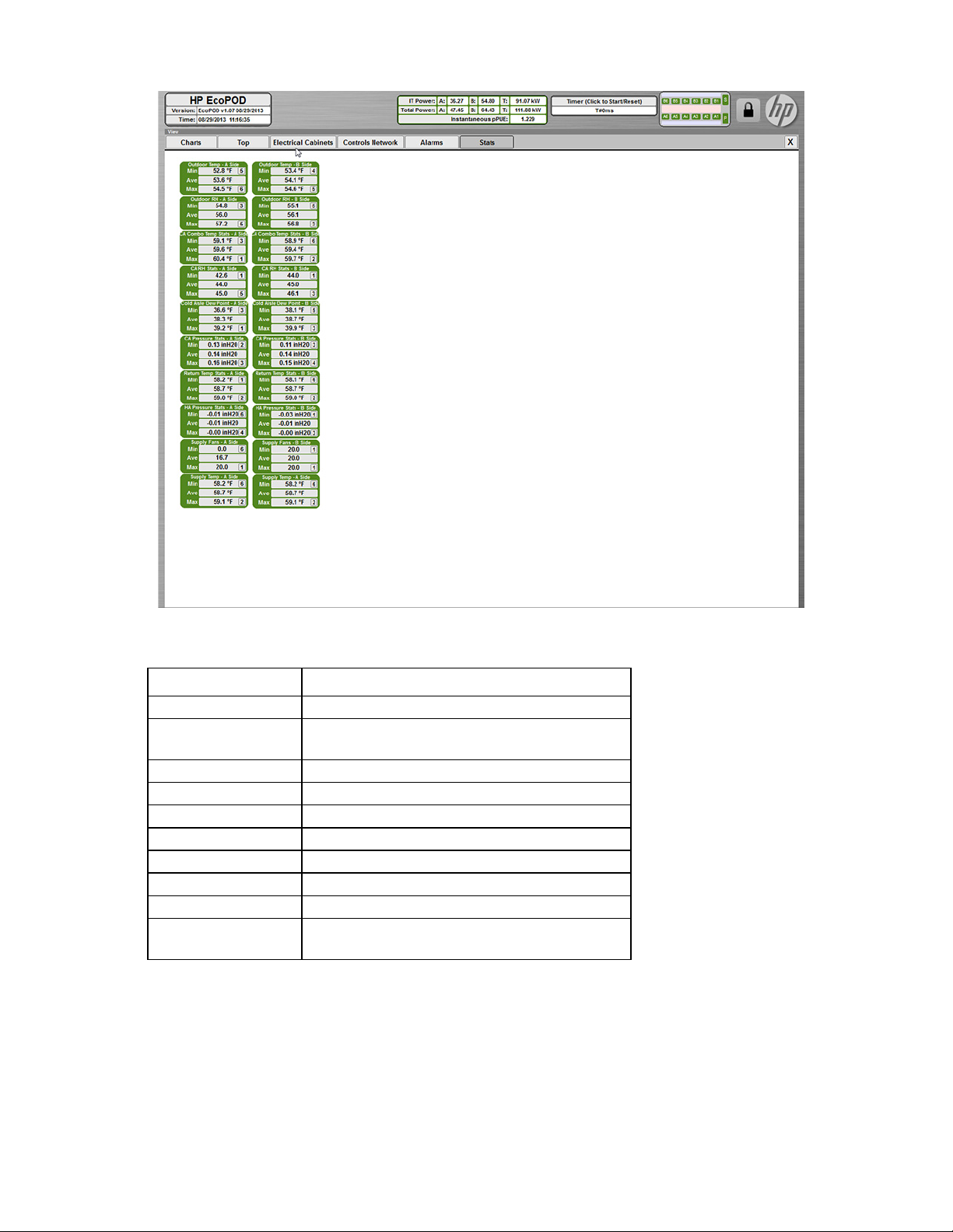
Stats screen
The Stats screen shows a list of minimum, maximum, and average sensor readings.
IMPORTANT: The ECS parameters must only be set by qualified service personnel.
Environmental control system 52
Page 53
Indicates the outdoor temperature
The Stats screen allows you to set the following minimum and maximum setpoint alarm ranges for IT section
A and IT section B.
Setpoint displayed Description
Outdoor temperature
Outdoor relative
Indicates the outdoor relative humidity
humidity
CA combo temperature
CA relative humidity
Cold aisle dew point
CA pressure
Return temperature
HA pressure
Supply fans
Min and Max value
sensor number
Indicates the cold aisle combination temperature
Indicates the cold aisle relative humidity
Indicates the cold aisle dew point
Indicates the cold aisle pressure
Indicates the return temperature
Indicates the hot aisle pressure
Indicates the supply fan percentage
Indicates the specific sensor that is reading the
minimum and maximum value for each statistic
Offset alarms can be configured to alert the BMS when an AHU sensor is offset by the average or median
from the remaining AHUs in the IT section. For more information, see "Setting the offset alarm (on page 57)."
Environmental control system 53
Page 54

Configure
You can see the Configure menu when you enter the customer-level password. This menu allows you to
configure alarm setpoints and Adiabatic control settings in the ECS system.
The following menus are available when you select the Configure menu:
• Control settings (on page 54)
• HMI settings (on page 55)
CAUTION: Making any change to the ECS in the customer-level area can cause the AHU to fail.
Only authorized, qualified, and trained personnel should change configuration settings in the
customer-level area of the ECS. Any changes to the configuration settings in the customer-level
area might void your warranty.
Control settings
IMPORTANT: You can only access this menu after you enter a customer-level password.
IMPORTANT: The ECS parameters must only be set by qualified service personnel.
The Control Settings menu displays the Adiabatic Control Settings for IT section A and IT section B. The
following settings can be configured from the Adiabatic Control Settings screen:
Environmental control system 54
Page 55
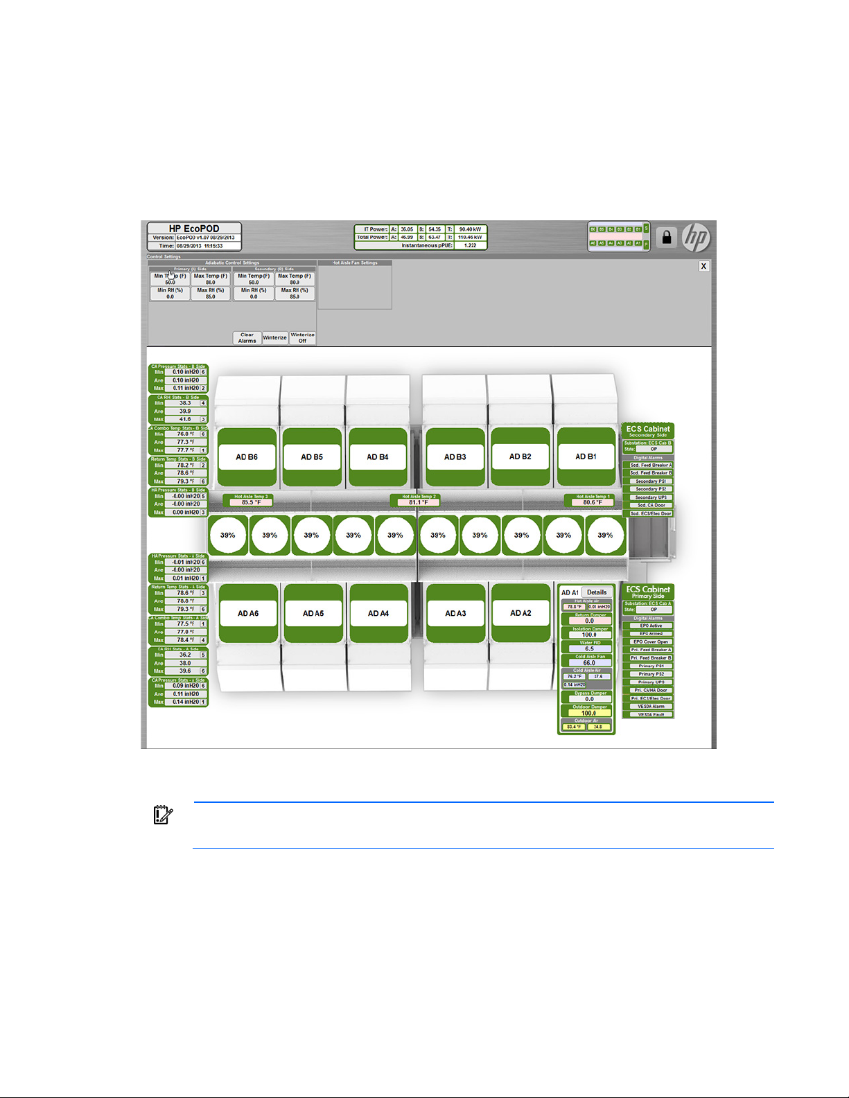
• Minimum and maximum temperature
• Minimum and maximum relative humidity
• Clear alarms
• Winterize
For more information on how to winterize the HP POD 240e NA, see "Preparing the Adiabatic units for
winter (on page 74)."
HMI settings
The HMI Settings menu allows you to change unit types that display measurement throughout the ECS system.
To change the HMI settings:
1. Select Configure on the main toolbar.
2. Select HMI Settings.
3. Press the Unit System button to toggle to the unit of measurement that you want the ECS system to
display. The choices are:
IMPORTANT: You can only access this menu after you enter a customer-level password.
Environmental control system 55
Page 56

o
US Customary
o Metric
Managing the ECS system
After you enter the customer-level password, you can manage various components within the HP POD 240e
NA using the ECS. You can configure every component by using the same basic steps and concepts,
Setting the Min and Max temperature and RH setpoints
described in this section.
You can configure the minimum and maximum temperature and relative humidity setpoints for each IT
section.
CAUTION: Making any change to the ECS in the customer-level area can cause the AHU to fail.
Only authorized, qualified, and trained personnel should change configuration settings in the
customer-level area of the ECS. Any changes to the configuration settings in the customer-level
area might void your warranty.
To set the minimum and maximum temperature and relative humidity setpoints:
1. Select Configure on the main toolbar.
2. Select Control Settings.
3. Select the button for the setpoint you want to change in IT section A or IT section B (Min Temp, Max
Temp, Min RH, Max RH).
A keypad appears.
4. Enter the setpoint for the desired minimum or maximum configuration.
5. Select Save to store the new setpoint in the system configuration file.
Setting the Min and Max range for alarms
Each sensor that is connected to the ECS system can activate a warning and critical alarm. You can configure
these alarms to alert you when the sensors fall out of a set range.
To set the range for alarms:
1. Select Min or Max on the alarm range you want to change.
2. Under the Range Warning and Critical heading:
a. Toggle to Enable TRUE.
Enable TRUE—The alarm range is active and alerts the ECS system.
Enable FALSE—The alarm range is inactive and does not alert the ECS system.
b. Click the Low button.
A keypad appears.
c. Set the Low point for the alarm range.
The Low alarm range is the lowest minimum measurement that the sensor can read before an alarm
becomes active in the ECS system.
d. Click the High button.
Environmental control system 56
Page 57

A keypad appears.
e. Set the High point for the alarm range.
The High alarm range is the highest maximum measurement that the sensor can read before an
alarm becomes active in the ECS system.
Setting the offset alarm
You can configure the offset alarm at a warning and a critical alarm level.
To set the offset alarm:
1. Click the sensor whose offset alarm you want to configure.
You will see a sensor count that shows the minimum amount of sensors or AHUs that can be read before
a warning or critical level alarm is triggered.
2. Toggle to Enable TRUE.
Enable TRUE—The alarm is active and alerts the ECS system.
Enable FALSE—The alarm is inactive and does not alert the ECS system.
3. Toggle to the alarm Method:
Average—The sensor offset is based on the average value in the IT section.
Median—The sensor offset is based on the median calculation of the IT section sensors.
4. Click the Warn. Offset button.
A keypad appears.
5. Enter how far out of range the sensor readings will be before the ECS triggers a warning alarm.
6. Press Enter.
7. Click the Crit. Offset button.
A keypad appears.
8. Enter how far out of range the sensor readings will be before the ECS triggers critical alarm.
9. Press Enter.
Setting the IP address
To set the static IP addresses:
1. Click the IP address.
A keypad appears.
2. Enter the IP address.
3. Select Save to store the new parameters in the system configuration file.
Forcing an alarm
Forcing an ECS component gives you the ability to override ECS readings. Some examples of how to force
a component include:
• Override an alarm
• Set fans on manual mode
Environmental control system 57
Page 58
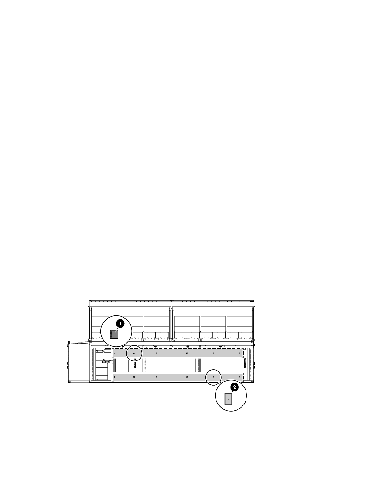
• Create an alarm to test the system
To enable forcing for a component:
1. Click the component you want to force.
2. Toggle to Forced TRUE.
TRUE—The alarm range is forced to an on/off state by user control.
FALSE—The alarm range is automatically controlled by the system alarm setpoints.
3. Click the setpoint, alarm, or speed that you want to force.
A keypad appears.
4. Enter the setpoint number you want to force on the component.
An F appears next to any component that is forced.
Maintaining the ECS parameters
For more information about how the HVAC system maintains the parameters set in the ECS, see the AHU
Temperature and pressure sensors
theory of operation (on page 62).
The HP POD 240e NA has several temperature and pressure sensors that monitor the environmental factors
and then communicate back to the ECS.
• The values from the temperature sensors are calculated together to determine an average temperature
for each aisle of the HP POD 240e NA.
• The pressure sensors in the IT sections measure the differential pressure between each sensor and the
external ambient pressure.
IT section sensors
Side view shown
Environmental control system 58
Page 59
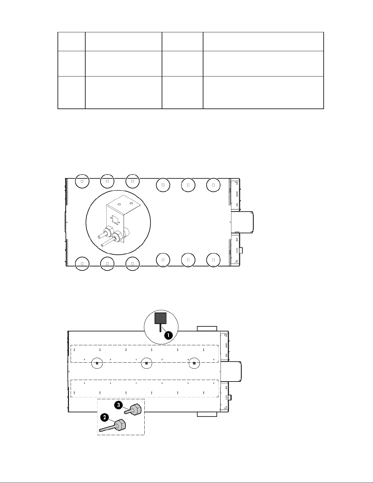
•
•
•
•
Callout Sensor Quantity per
Description
IT section
1
Temperature and relative
humidity sensors
6
Monitor the temperature and humidity in the
six Adiabatic zones of the HP POD 240e NA
Report data to the AHU controllers
2
Differential pressure sensor
port
6
Works in combination with the AHU sensors to
monitor pressure in the six Adiabatic zones of
the HP POD 240e NA
Reports data to the AHU controllers
HVAC sensors
Six AHU temperature and pressure sensor probes work in combination with the differential pressure sensor
port, callout (2) in the figure above, to calculate the cooling unit discharge temperature and average pressure
in each IT section. This data is reported to the AHU controllers.
Top view shown
Hot aisle sensors
Top view shown
Environmental control system 59
Page 60

•
•
•
•
•
•
Callout Sensor Quantity per
1
2
3
Temperature sensors 3
Hot aisle pressure sensor
probes
Hot aisle temperature sensor
probes
Outdoor air sensors
There is one sensor mounted on each Adiabatic unit that monitors the temperature and humidity of the
outdoor air. Each sensor reports the data to the AHU controller.
Adiabatic units
Each IT section of the HP POD 240e NA has six Adiabatic units that maintain the differential pressure and
temperature parameters within the HP POD 240e NA.
hot aisle
12
12
Description
Monitor the temperature in various locations
throughout the hot aisle of the HP POD 240e
NA
Report data to the ECS
Monitor and report hot aisle pressure
Report data to the AHU controllers
Monitor and report hot aisle temperature
Report data to the AHU controllers
For more information about the required power for the Adiabatic units, see "Power distribution: Adiabatic
system (on page 28)."
Controlling the hot aisle fans
There are 10 exhaust fans located in the hot aisle of the HP POD 240e NA.
Side view shown
The HP POD 240e NA fans operate at variable speeds (0-100%) to maintain predetermined parameters
programmed into the AHU. For more information about the fan mode, see "AHU theory of operation (on
page 62)".
Environmental control system 60
Page 61

AHU system
Inclement weather
Prevents snow or heavy rain from entering the Adiabatic unit. The inclement
Overview
The POD AHU systems are designed to condition the air in a portable, containerized computer room, and
are installed directly on top of the HP POD 240e NA. The HP POD 240e NA includes a total of four cradles,
each holding 3 Adiabatic units, for a total of 12 Adiabatic units.
The AHU system requires a potable water source and HP highly recommends installing a filter to be sure that
water is free of particles. For more information about water requirements, see the HP Performance Optimized
Adiabatic components
Datacenter 240e NA Site Preparation and Requirements Guide.
Each Adiabatic unit is housed in a NEMA 3 rated steel frame cabinet that is rated for outdoor use. The
exterior of the cabinet is coated with a durable finish to protect against corrosion. Access panels are located
on the front and on the rear of the cabinet for easy access to all of the components. The access panels are
safety interlocked with the power disconnect switch to prevent the removal of the panel when the switch is in
the ON position. The power disconnect switch must be turned OFF to gain access to the electrical
compartment.
Side view shown
Item Component Description
1
2
3
Lifting eyes
hood
Access panel to the
damper actuator
*
For crane attachment to lift the Adiabatic unit during assembly
weather hood is also equipped with a screen to prevent birds and other small
animals from nesting in the air inlet opening.
Provides access to the damper actuator motor
AHU system 61
Page 62
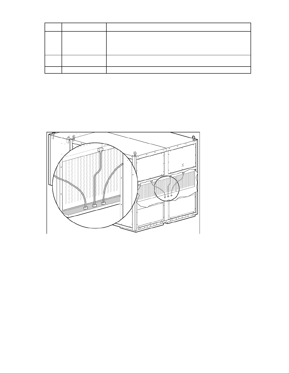
Item Component Description
Power disconnect
The main power supply switch for each Adiabatic unit
4
5
6
*
Use the lifting eyes on top of the unit to lift the Adiabatic unit. Do not lift the Adiabatic unit with the lifting eyes installed
on the filter box.
Filter box Louvers and dampers provide an outside air inlet of each Adiabatic unit. If the
switch
Electrical controls box Houses the electrical controls and components
Adiabatic media
Each Adiabatic unit contains three Adiabatic media, each with its own solenoid water supply valve. An
outside source of water must be provided to saturate the media.
HP recommends potable water as the main water source for the media.
outside air temperature and humidity conditions are within the correct range of
the operating envelope, the dampers open automatically when the AHU is
powered on.
AHU theory of operation
Damper operation
Each Adiabatic unit is equipped with louvered dampers that control the airflow through the unit. To control
the environment inside of the HP POD 240e NA, the dampers work together to humidify dry outside air, as
needed.
An external source of water must be provided to saturate the evaporative media. When the HP POD 240e
NA begins operation, the supplied water is pumped through the pipes and out of the nozzles from the
reservoir to the top of the evaporative media where it passes through spray nozzles onto the top of the
evaporative media. The air that is pulled in through the media by the POD fans is now conditioned.
The controller sends an analog output signal to operate the outside air damper (1) by modulating it. Next, the
bypass damper (2), the isolation damper (3), and the hot aisle return damper (4) are controlled to optimize
the balance of outside air with humidified air in order to maintain the conditions in the IT section. The
AHU system 62
Page 63
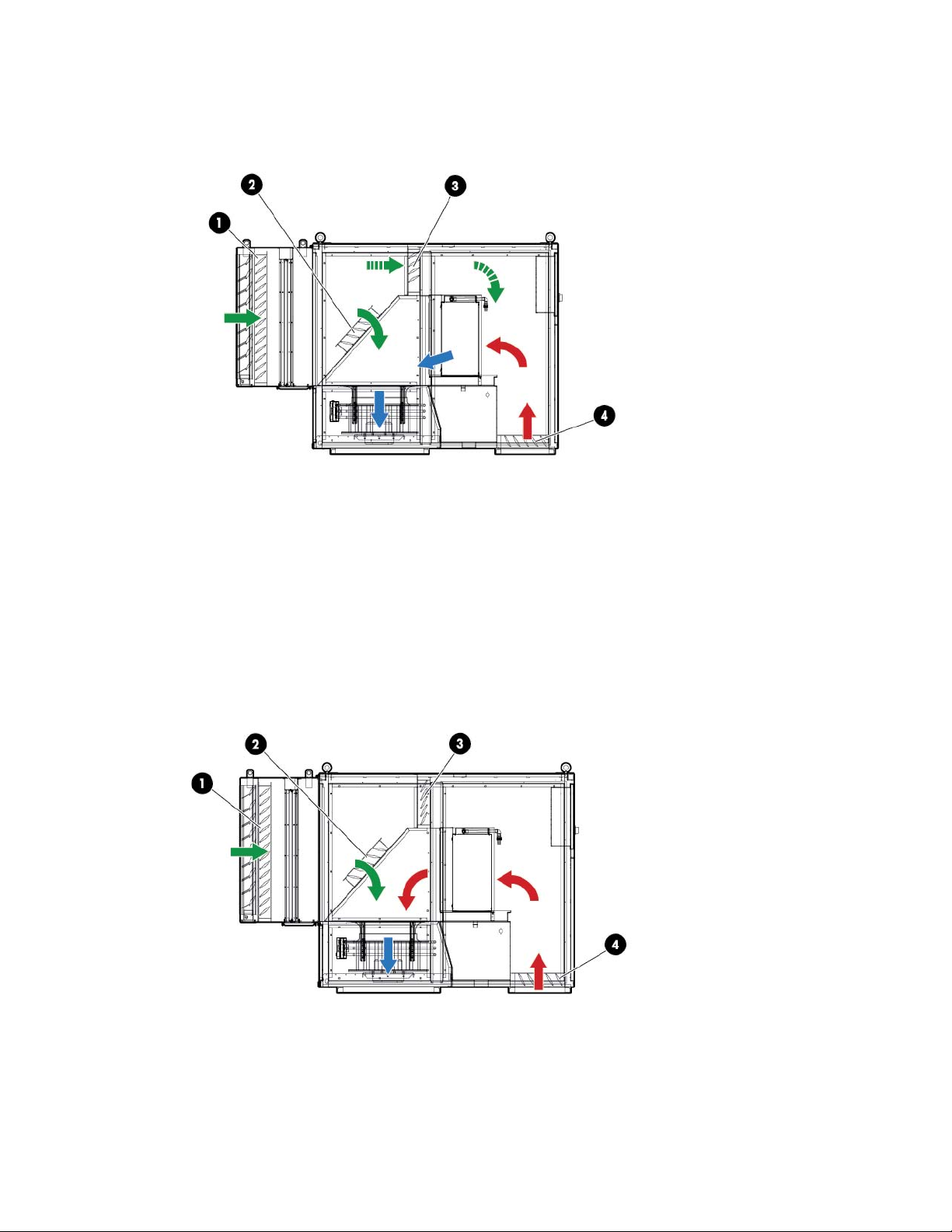
isolation damper (3) is used to isolate the dry side of the Adiabatic unit from the wet side during cold weather
operation.
Below freezing damper operation
The isolation damper (3) is completely closed, so that sub freezing air cannot get to the wet media. The
bypass damper (2) is completely open, enabling a path for the cold, dry air to enter the IT sections. The
outside air damper (1) and hot aisle return damper (4) moderate to maintain a set temperature within the IT
sections.
If the humidity within the HP POD 240e NA gets too low, water is added to the media to maintain the low RH
humidity parameter, unless the ECS is set to Allow Low RH.
For more information on winterizing the HVAC/ Adiabatic units, see "Preparing the HVAC units for winter."
Side view shown
Economizer without additional cooling requirements
AHU system 63
Page 64

The bypass damper (2) and isolation damper (3) are both completely open, to optimize airflow efficiency.
The outside air damper (1) and hot aisle return damper (4) moderate to maintain a set temperature within the
IT sections.
Side view shown
Hot weather damper operation
The hot aisle return damper (4) is completely closed, so that the air returning from the hot aisle is not
recirculated through the Adiabatic unit. The outside air damper (1) and the isolation damper (3) are both
completely open to optimize airflow efficiency. The bypass damper (2) modulates to maintain the humidity
parameter.
Water is added to the media to cool the outdoor air, while still maintaining the humidity in the IT sections
below the max RH parameter.
Side view shown
Exhaust fan operation
AHU system 64
Page 65
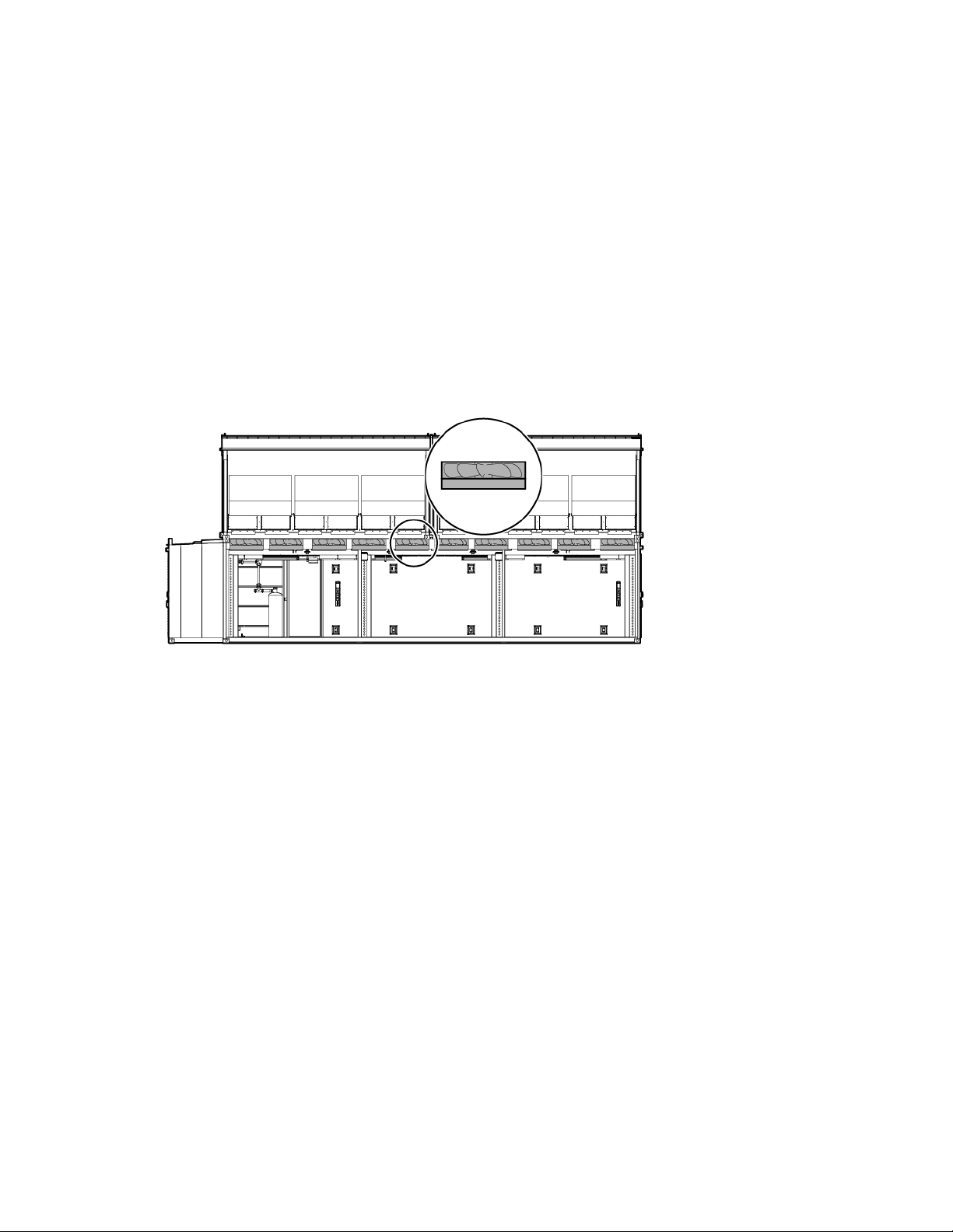
The HP POD 240e NA is equipped with 10 exhaust fans that remove heated air from the hot aisle. The
exhaust fans feature an integrated monitoring function to protect the motor and electronics against damage
from jamming, phase loss, or overheating.
If any of the following failure conditions occur, the motor automatically stops and an alarm is signaled:
• Locked rotor
• Low main supply voltage
• Loss of a phase
• Over-heating of the exhaust fan electronics
• Over-heating of the exhaust fan motor
For more information about the exhaust fan, see the HP Performance Optimized Datacenter 240e NA
Maintenance and Service Guide.
Side view shown
Static pressure control
The control of static pressure is used to be sure that the airflow from the cold aisle of the IT sections across the
rack and into the hot aisle of the HP POD 240e NA remains constant. The pressure in the hot aisle is
controlled to external ambient pressure, and the IT sections are slightly higher than the external ambient
pressure.
The static pressure is controlled to a default parameter of 0.1 in H
cold aisle, which cannot be adjusted by a customer.
O above external ambient pressure in the
2
AHU system 65
Page 66

IT networking and communications
Networking connection for all IT
4
8
•
•
•
•
Networking
Connecting the HP POD 240e NA to the facility network is a vital part of confirming the functionality of the
various communication systems. Due to the different customer equipment and networking setups, see the HP
Performance Optimized Datacenter 240e NA Networking Guide for more information.
You are responsible for all connections. For configuration and installation instructions, consult with HP.
Connection portals
The networking and connection portals are located on both ends of the HP POD 240e NA.
Each IT section has eight portals located on the cargo-end of the POD, and each of the differently sized
portals are used for different connections.
End view shown
Connection portal
diameter
7.62 cm (3 inch)
3.81 cm (1.5 inch)
3.81 cm (1.5 inch)
Connection point Quantity per IT
section
Communication connection for:
ECS
EPO
Fire alarm
Phone
(Optional) vestibule communication
connections
2
2 4
IT networking and communications 66
Total quantity per
HP POD 240e NA
4
Page 67

On the front-end of the POD, there are seven 7.62 cm (3 inch) portals that you can use for data connections.
The connection portal location and configuration might look different, depending
End view shown
IMPORTANT:
on the HP POD 240e NA model.
Demarcation box
The following communication connections between your facility and the HP POD 240e NA are made
through the demarcation box:
• ECS communication
• Access control communication
• Phone
End view shown
IT networking and communications 67
Page 68

You must make the connections between the facility and the HP POD 240e NA. For configuration and
installation instructions, consult with HP.
Fire box
The communication connections between the site fire system and the HP POD 240e NA are made through the
fire box.
Front view shown
You must make the connections between the facility and the HP POD 240e NA. For configuration and
installation instructions, consult with HP.
Adding a phone
The HP POD 240e NA has a junction box location in each section that you can wire to install a telephone.
There are a total of three junction box locations throughout the HP POD 240e NA.
IT networking and communications 68
Page 69

Top view shown
You must provide and install the phones, including pulling cables to the appropriate junction box. For
configuration and installation instructions, consult with HP.
IT networking and communications 69
Page 70

Standard components
Air filter sensor
There is an air filter sensor in each Adiabatic unit that sends an alert for any change in the air filter status. If
an air filters needs replacement, the sensor sends an alert to the ECS and identifies the exact Adiabatic unit
affected. Each Adiabatic unit has four air filters, all of which must be replaced after an alarm triggers.
CAUTION: Replace air filters upon notification from the ECS to maintain optimal air flow. For
replacement instructions and information about the air filter media pack, see the HP Performance
Optimized Datacenter 240e NA Maintenance and Service Guide.
Standard components 70
Page 71

Optional components
HP POD 240e NA optional components
There are several optional components available for the HP POD 240e NA, including but not limited to:
• Controlled access
• Power feeder pull boxes
For more information about optional components, see the Operations and Maintenance Manual for the HP
Power feeder pull boxes
Performance Optimized Datacenter 240e North America (Adiabatic).
The HP POD 240e NA requires power feeder pull boxes for the electrical cabinets to prevent water from
getting into the POD through the connection portals. The pull boxes can be customized to the facility and
configuration of the power feeders.
For more information about the power feeder pull boxes, see the Operations and Maintenance Manual for
the HP Performance Optimized Datacenter 240e North America (Adiabatic).
Optional components 71
Page 72

Specifications
•
•
•
•
•
Bulk cable pass through fiber
General specifications
Features Specifications
Overall dimensions
Weight1
Power input voltage
Power distribution
Maximum rack quantity
RUs per rack
RU total
Peak rack capacity
Voltage to rack
Minimum quantity of PDUs per HP POD 240e
NA
Maximum quantity of PDUs per HP POD 240e
NA
Maximum power per PDU
Network supported
1
Empty weight includes the HP POD 240e NA structure, empty racks, PDUs, and drop boxes. It does not include any IT
equipment. All weights are estimates and can vary for your POD.
2
Can be configured for redundancy or non-redundancy
Height—6.74 m (22 ft 1 1/4 inches)
Length—13.77 m (45 ft 2 1/4 inches) including hot aisle
porch
Width—9.53 m (31 ft 3 inches) with cradles and hoods
installed
Empty—66,859 kg (147,400 lb)
Full—138,309 kg (304,920 lb)
IT equipment—415/240V, 3-phase, wye, 4 wire
Adiabatic system—415/240V wye
2
200A electrical busways
44 racks
50 RU
2,200 RU
69.12 kW
240V
44 (one per rack)
88 (two per rack)
34.56 kW
Bulk cable pass through copper
(Optional) External-rated demarcation box
Rack specifications
Standard HP POD 240e NA racks (AT978A)
Feature Specification
U height
Width
Depth
Maximum load weight
50U
54.6 cm (21.5 in)
87.6 cm (34.5 in)
1,360.7 kg (3,000 lb)
Specifications 72
Page 73

•
•
Environmental specifications
Feature Specification
Operating temperature
Non-operating temperature*
Operating humidity
Non-operating humidity*
Operating altitude
Non-operating altitude
*For non-operating specifications, consider the temperature of computer and IT equipment inside the HP POD 240e NA.
-28ºC to 54ºC (-20ºF to 130ºF)
-29ºC to 54ºC (-20ºF to 130ºF)
0% to 100% relative non-condensing
5 to 95% relative non-condensing
39ºC (102ºF) maximum wet bulb
temperature
-76.2 to 3,048 m (-250 to 10,000 ft)
-76.2 to 9,144 m (-250 to 30,000 ft)
Specifications 73
Page 74

Maintenance
in reduced efficiency in the HP POD 240e NA, failure of main or subsidiary systems, and loss of
Periodic maintenance
Perform periodic inspections to ensure that the HP POD 240e NA continues to perform according to design
parameters. During periodic inspections, pay special attention to electrical connections and wiring.
You are responsible for creating and performing detailed preventative maintenance based on HP
recommendations. Data sheets or additional operation and maintenance manuals will be provided for this
task.
CAUTION: Failure to implement a comprehensive preventative maintenance schedule may result
warranty on third party components.
For more specific maintenance information, see the HP Performance Optimized Datacenter 240e NA
Maintenance and Service Guide.
Preparing the Adiabatic units for winter
CAUTION: Because the Adiabatic units use water, you must take extra precautions during the
winter months to establish safe operating conditions of the HP POD 240e NA.
IMPORTANT: HP recommends contacting your HP representative prior to winterizing your HP
There are three major processes that you must complete to winterize the HP POD 240e NA Adiabatic units.
Complete the following processes in the following order:
1. Supply header gravity drain (on page 76)
2. Adiabatic unit by unit blowdown (on page 77)
3. Supply header blowdown (on page 78)
Your site or POD might have different component locations or a different number of Adiabatic units.
You will need the following items to winterize the Adiabatic units:
• Air hose adapter—Connects the house air or compressor to the supply header.
• Adiabatic unit splash deflector—Used inside of each Adiabatic unit to prevent unnecessary splashing.
POD 240e NA for further instructions.
This splash deflector consists of a hose barb adapter and enough flexible tubing to direct water to the
drain.
Maintenance 74
Page 75
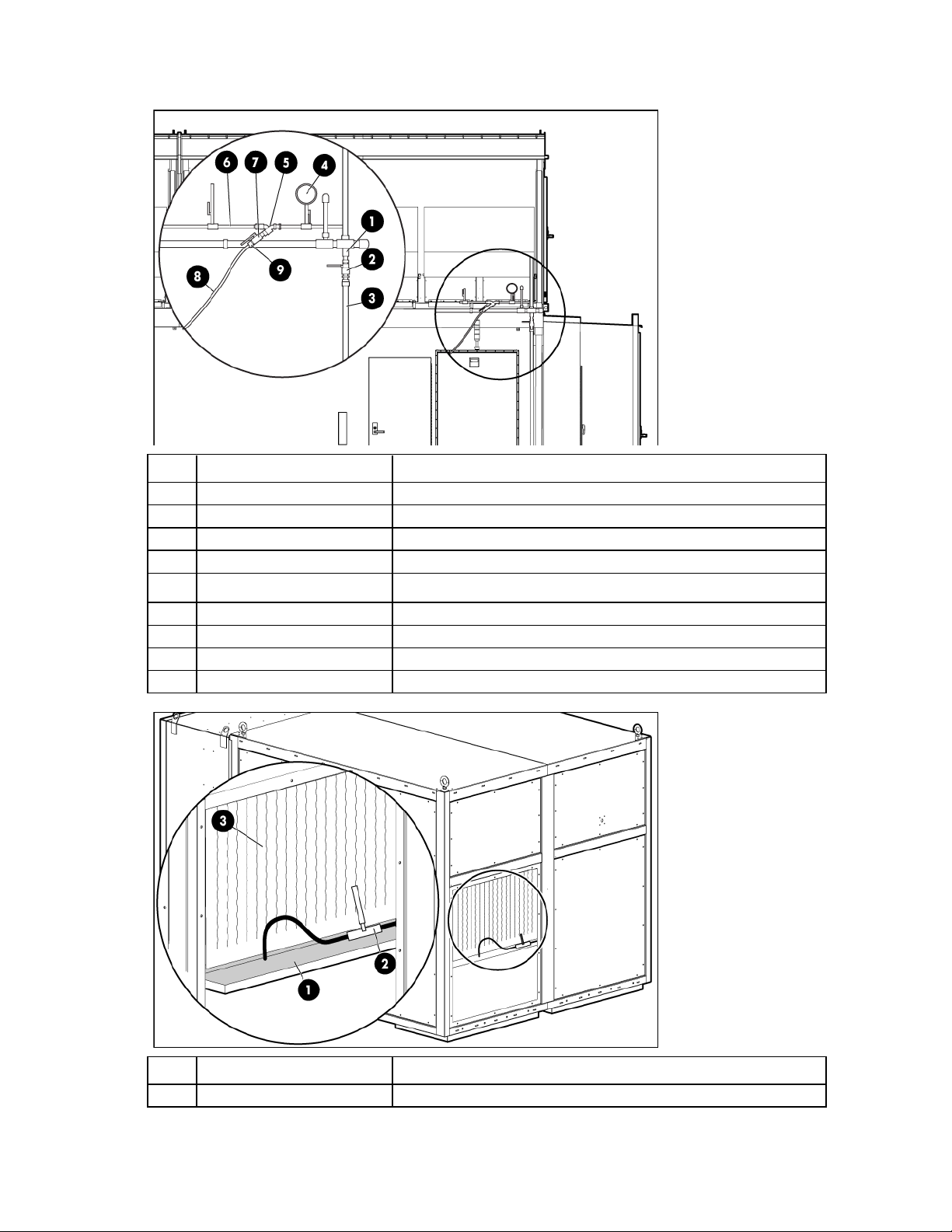
• Garden hose and fitting—Connects to the supply header drain.
Y-strainer
Allows for suspended solids to be removed from the supply valve water
Item Component Description
1
2
3
4
5
6
7
8
9
Drain line Allows for drainage from the cooling media supply water
Drain valve Isolation valve for the drain line
Drain hose Customer-supplied hose connector
Blowdown pressure gauge Optional gauge that can be added to the supply header
Supply header Cooling media supply water
Y-strainer clean-out valve Allows for a blowdown of the y-strainer
Air hose Customer-supplied from an air compressor or site air supply
Air hose connector Customer-supplied to connect a valve to an air hose
Item Component Description
1
Drain pan Collects excess media water from the Adiabatic unit
Maintenance 75
Page 76

Item Component Description
2
3
Adiabatic media nozzle drain Isolation valve for the drain valve
Adiabatic media Used for AHU cooling
Supply header gravity drain
The AHU solenoids are actuated to provide back pressure relief and allow the system to drain. In order to
drain the system from the high point located at the Adiabatic media spray bar down to the low point of the
supply drain, complete the following steps:
1. Close all of the site AHU supply header isolation valves to the HP POD 240e NA.
2. Remove the installed plug from the supply header drain line and attach the water hose from the drain
line to a site drain, if possible.
3. Place the ECS system of the HP POD 240e NA in Winterization mode:
a. On the ECS panel in IT section A, select the lock icon and type 'hpinvent'.
b. Press the Enter button.
c. Select the configure button from the Top View or AD detail screens.
d. Select the Winterize button.
e. The media spray solenoid valves of the Adiabatic units open.
4. If the supply system contains a relief or vent valve, open or pin the valve open to maximize drain
capabilities.
5. Open the supply header isolation ball valve by rotating the handle 90º counter-clockwise to align the
handle parallel to the ball valve.
The Adiabatic supply header is now draining.
6. When water stops flowing from the supply header, close the drain line ball valve by rotating the handle
90º clockwise to align the handle perpendicular to the ball valve.
7. If the time limit on ECS system Winterization mode has not elapsed, manually turn off the Winterization
mode to close the media spray solenoid valves:
a. On the ECS panel in IT section A, select the lock icon and type 'hpinvent'.
b. Press the Enter button.
c. Select the configure button from the Top View or AD detail screens.
d. Select the Winterize off button.
e. The media spray solenoid valves of the Adiabatic units close.
8. Close the relief or vent valve that was opened during step 4, if applicable.
IMPORTANT: Both Aisle A and Aisle B of the Adiabatic units must be drained to complete the
Winterization process of the HP POD 240e NA.
Continue preparing the Adiabatic units for winter by completing the Adiabatic unit by unit blowdown (on
page 77).
Maintenance 76
Page 77

Adiabatic unit by unit blowdown
rized. This air pressure must
Before you begin the process below, be sure to complete the steps in "Supply header gravity drain (on page
76)."
These steps allow low pressure air to force water from the AHU supply header through an additional drain
that is located inside the access panel of each Adiabatic unit.
1. Remove the plug from the supply header debris Y-strainer.
2. Open the flushing ball valve by rotating the handle 90º until it is aligned parallel to the strainer and
allow the Y-strainer to drain.
3. Connect the air hose from the site or from a portable compressor to the open Y-strainer connection using
an air hose adapter.
4. Connect the air hose to the air source.
If you use a compressor, start the compressor and then open the air isolation valve from the chosen
source.
CAUTION: Maximum allowable air pressure in the Adiabatic water supply header is 50 psi. Do
not exceed this pressure at any time.
5. Move to the AHU service area of the POD.
6. Shut down power to the Adiabatic unit that is farthest from the air source by rotating its power switch to
the Off position.
IMPORTANT: Only blow down one Adiabatic unit per aisle at a single time. Failure to do this will
disrupt optimal air flow in the POD.
7. Open or remove the media access cover to the left of the Adiabatic unit control panel that was just
turned off to show the inside of the unit.
8. Locate the spray nozzle header assembly drain line.
9. Attach the splash deflector finger-tight. Position the tubing so that blow down water is deflected into the
drain pan, which minimizes splashing.
10. Carefully open the spray nozzle header drain valve. Be sure to apply air pressure to the spray header
and observe that the splash deflector is in place.
11. Close the drain valve when either water stops flowing or air pressure is depleted.
12. Repeat steps to open and close the drain valve until no water exits through the drain valve.
13. Close the nozzle header drain valve.
14. Locate and close the external Adiabatic unit spray nozzle header isolation ball valve to isolate the unit
from site water.
IMPORTANT: The external spray nozzle header may still be pressu
be relieved.
15. Open the spray nozzle header drain valve to allow the header to de-pressurize.
16. Close the spray nozzle header drain valve.
17. Remove the splash deflector and replace or close the media access cover.
18. Repeat steps to open and close the drain nozzle to complete blowing down the Adiabatic units on this
aisle.
Maintenance 77
Page 78

Continue preparing the Adiabatic units for winter by completing the instructions in "Supply header
blowdown (on page 78)."
Supply header blowdown
Before you begin the process below, be sure to complete the steps in the following sections:
1. Supply header gravity drain (on page 76)
2. Adiabatic unit by unit blowdown (on page 77)
Be sure that all Adiabatic units are isolated from the supply header. If all Adiabatic units are not isolated from
the supply header, see "Adiabatic unit by unit blowdown (on page 77)." To be sure the maximum amount of
water is removed from the entire supply header(s), complete the following steps:
IMPORTANT: Be sure air pressure is available to complete the next steps.
1. Pressurize the supply header to 20-50 psi with a pressure gauge, if installed, and close the Y-strainer
flushing valve.
2. Open the supply header drain valve to release the air pressure and water.
3. Close the supply header drain valve when the header pressure is zero.
4. Repeat the steps to open and close the drain valve for five cycles, or until no water remains.
At this point, all headers are at atmospheric pressure, all water is removed from the system, and all
power is removed at each Adiabatic unit.
5. Remove the garden hose and air adapter assemblies, and then replace the previously removed plugs.
Maintenance 78
Page 79

Power up procedure
Standard power up procedure
This procedure is for reference only and assumes that the POD is fully commissioned and powered up by HP
before being turned over to you.
Before you begin the power up procedures in this section, verify that the POD is not in operation and that the
internal ambient temperature of the POD is greater than 10ºC (50ºF). If the internal ambient temperature of
the POD is less than 10ºC (50ºF), see "Cold weather power up procedure (on page 80)."
This process helps to be sure that personnel are safe during the electrical power up of the HP POD 240e NA.
WARNING: To avoid risk of personal injury or loss of life, do not open an energized POD
Power up checklist
Site electrical
electrical cabinet without an energized work permit and appropriate PPE.
• Verify that all site POD critical IT feeder supply breakers are open.
• Verify that all site Adiabatic mechanical feeder supply breakers are open.
POD electrical
• Service aisle—Verify that all site Adiabatic unit service disconnects are open.
• Hot aisle—Verify that all IT power drop box breakers on the power tap boxes are open.
IMPORTANT: Following these steps prevent any possibility of energizing the IT load.
• IT sections A and B:
a. Close all non-spare breakers and fuses within the control cabinet.
b. Close and latch the control cabinet.
c. Position the EPO system (on page 19) to Armed (white) or Bypass (green).
d. Verify that all EPO activation buttons are in the reset position (not depressed).
• IT critical power feed cabinets A and B:
a. Close all non-spare breakers within primary A and B and secondary A and B power supply
cabinets.
b. Close and lock electrical cabinet doors.
c. Close all Adiabatic power supply feeder breakers in both the primary mechanical and secondary
mechanical cabinets.
d. Close and lock Adiabatic primary mechanical and secondary mechanical cabinets.
Standard power up procedure
Perform the following procedures in the exact order in which they are listed.
Maintenance 79
Page 80

Electrical
Site electrical
1. Close all site POD critical IT power feeder supply breakers and monitor them for any effects that are not
standard.
2. Close all site Adiabatic mechanical feeder supply breakers and monitor them for any effects that are not
standard.
POD electrical
Close all of the site Adiabatic unit service disconnects in the service aisle.
ECS and EPO
Verify the following on using the ECS touchscreen and EPO indicators:
• The ECS panel is operational and displays the user interface.
• The POD lighting is operational.
• The EPO system is set to Armed (White) or Bypass (Green).
Standard operation
1. On the ECS touchscreen, verify that all system components are operational (green) and no alarm
conditions exist.
2. On the ECS touchscreen, verify the operating envelope is accurate.
3. Wait five minutes to allow the system to stabilize.
4. In the hot aisle, close the power drop box breakers for each rack and be sure that the IT equipment is
operating.
5. Wait five minutes to allow the system to stabilize.
The HP POD 240e NA is now fully operational and the control system monitors for proper environmental
control operation.
Cold weather power up procedure
This procedure is for your reference only and is written with the assumption that HP fully commissioned and
powered up the POD before turning it over to you.
Before you begin the power up procedures in this section, verify that the POD is not in operation and that the
internal ambient temperature of the POD is less than 10ºC (50ºF). If the internal ambient temperature of the
POD is greater than 10ºC (50ºF), see "Standard power up procedure (on page 79)."
IMPORTANT: The minimum acceptable inlet temperature for IT equipment is 10ºC (50ºF).
Following this process helps to be sure that personnel are safe during the electrical power up of the HP POD
240e NA.
WARNING: To avoid risk of personal injury or loss of life, do not open an energized POD
This procedure requires a method of warm air generation in sufficient quantities to increase the internal
temperature of the POD and maintain a temperature of 12ºC (53ºF) for a minimum of 6 to 12 hours. The
electrical cabinet without an energized work permit and appropriate PPE.
Maintenance 80
Page 81

method to supply warm air is your responsibility. HP will advise on warm air alternatives; however, all
references to warm air production are your responsibility during this procedure.
Cold weather power up checklist
Site electrical
• Verify that all site POD critical IT feeder supply breakers are open.
• Verify that all site Adiabatic mechanical feeder supply breakers are open.
POD electrical
• Service aisle—Verify that all site Adiabatic unit service disconnects are open.
• Hot aisle—Verify that all IT power drop box breakers on the power tap boxes are open.
IMPORTANT: Following these steps prevent any possibility of energizing the IT load.
• IT sections A and B:
a. Close all non-spare breakers and fuses within the control cabinet.
b. Close and latch the control cabinet.
c. Position the EPO system (on page 19) to Armed (white) or Bypass (green).
d. Verify that all EPO activation buttons are in the reset position (not depressed).
• IT critical power feed cabinets A and B:
a. Close all non-spare breakers within primary A and B and secondary A and B power supply
cabinets.
b. Close and lock electrical cabinet doors.
c. Close all Adiabatic power supply feeder breakers in both the primary mechanical and secondary
mechanical cabinets.
d. Close and lock Adiabatic primary mechanical and secondary mechanical cabinets.
Standard power up procedure
Perform the following procedures in the exact order in which they are listed.
Electrical
Site electrical
1. Close all site POD critical IT power feeder supply breakers and monitor them for any effects that are not
standard.
2. Close all site Adiabatic mechanical feeder supply breakers and monitor them for any effects that are not
standard.
POD electrical
Close all of the site Adiabatic unit service disconnects in the service aisle.
Maintenance 81
Page 82

ECS and EPO
Verify the following using the ECS touchscreen and EPO indicators:
• The ECS panel is operational and displays the user interface.
• POD lighting is operational.
• The EPO system is set to Armed (White) or Bypass (Green).
Cold weather operation
1. On the ECS touchscreen, determine internal and external ambient temperatures.
2. On the ECS touchscreen, verify that all system components are operational (Green) and no alarm
conditions exist.
3. On the ECS touchscreen, determine the internal POD temperature.
4. Begin warm air generation in the hot aisle.
5. On the ECS touchscreen, monitor the POD internal temperature and continue warm air generation until
all internal indicators show the internal temperature is 12ºC (53ºF).
6. Maintain POD internal temperature above 12ºC (53ºF) for a minimum of 6 to 12 hours before you
proceed to the next step.
7. Stop warm air generation in the hot aisle.
8. On the ECS touchscreen, select and write the appropriate operating mode to the Adiabatic units.
9. In the hot aisle, close the power drop box breakers for each rack and be sure that the IT equipment is
operating.
10. On the ECS touchscreen, monitor POD operation.
Continue to monitor POD operation for the next hour to verify that it stabilizes.
The HP POD 240e NA is now fully operational and the control system monitors for proper environmental
control operation.
Maintenance 82
Page 83

Power down procedure
Full power down procedure
This procedure completely powers down the HP POD 240e NA and is intended for personnel safety during
the full power down of the POD.
WARNING: To avoid risk of personal injury or loss of life, POD electrical cabinets should be
To power down the HP POD 240e NA:
1. Power down all IT equipment in IT sections A and B.
2. Open all POD power drop box breakers in the hot aisle.
3. Open all Adiabatic unit service disconnects in the service aisle.
4. Open the site critical IT feeder supply breakers.
5. Open the site Adiabatic feeder supply breakers.
The HP POD 240e NA is now fully powered down.
closed at all times.
Maintenance 83
Page 84

Contacting HP
Before you contact HP
Be sure to have the following information available before you call HP:
• Active Health System log (HP ProLiant Gen8 or later products)
Download and have available an Active Health System log for 3 days before the failure was detected.
For more information, see the HP iLO 4 User Guide or HP Intelligent Provisioning User Guide on the HP
website (http://www.hp.com/go/ilo/docs).
• Onboard Administrator SHOW ALL report (for HP BladeSystem products only)
For more information on obtaining the Onboard Administrator SHOW ALL report, see the HP website
(http://www.hp.com/go/OAlog).
• Technical support registration number (if applicable)
• Product serial number
• Product model name and number
• Product identification number
• Applicable error messages
• Add-on boards or hardware
• Third-party hardware or software
• Operating system type and revision level
HP contact information
For United States and worldwide contact information, see the Contact HP website
(http://www.hp.com/go/assistance).
In the United States:
• To contact HP by phone, call 1-800-334-5144. For continuous quality improvement, calls may be
recorded or monitored.
• If you have purchased a Care Pack (service upgrade), see the Support & Drivers website
(http://www8.hp.com/us/en/support-drivers.html). If the problem cannot be resolved at the website,
call 1-800-633-3600. For more information about Care Packs, see the HP website
(http://pro-aq-sama.houston.hp.com/services/cache/10950-0-0-225-121.html).
Contacting HP 84
 Loading...