

Page 1

HP Performance Optimized Datacenter (POD)
240a
Site Requirements Guide
Part Number: 663155-001
October 2011
Edition: 1
Page 2

© Copyright 2011 Hewlett-Packard Development Company, L.P.
The information contained herein is subject to change without notice. The only warranties for HP products and services are set forth in the express
warranty statements accompanying such products and services. Nothing herein should be construed as constituting an additional warranty. HP shall
not be liable for technical or editorial errors or omissions contained herein.
Page 3

Contents
Overview ..................................................................................................................................... 5
About this document .................................................................................................................................. 5
Site assessment ......................................................................................................................................... 5
Site requirements .......................................................................................................................... 6
HP Site Preparation Drawing Package ......................................................................................................... 6
Site preparation ........................................................................................................................................ 6
Early infrastructure requirements .................................................................................................................. 6
Site pad ......................................................................................................................................... 7
Other structures ............................................................................................................................... 7
Space requirements and clearances ................................................................................................ 8
HP POD 240a dimensions and required clearances ....................................................................................... 8
HP POD 240a weight .............................................................................................................................. 10
HP POD 240a and support equipment sample offload plan ................................................................ 10
Site space and clearance requirements ...................................................................................................... 11
Additional equipment space requirements .................................................................................................. 11
Future expansions .................................................................................................................................... 11
Preparing for delivery and assembly ............................................................................................. 12
Shipping considerations ........................................................................................................................... 12
Suggested assembly installation equipment ................................................................................................. 12
Safety for assembly ........................................................................................................................ 12
Temporary lighting and power .................................................................................................................. 13
Storage requirements ............................................................................................................................... 13
Assembly prerequisites ............................................................................................................................. 13
Environmental considerations ....................................................................................................... 14
Environmental considerations .................................................................................................................... 14
Cold weather .......................................................................................................................................... 14
Areas prone to lightning or power surges ................................................................................................... 14
Seismic activity ....................................................................................................................................... 14
Utilities ...................................................................................................................................... 15
Proximity to utilities and drains .................................................................................................................. 15
System utilities......................................................................................................................................... 15
Water supply ................................................................................................................................ 15
Drainage ...................................................................................................................................... 16
Power .......................................................................................................................................... 17
Required facility connections ........................................................................................................ 19
Connections to central facility infrastructure ................................................................................................ 19
Network connections ............................................................................................................................... 19
Connection portals ........................................................................................................................ 19
Grounding requirements ........................................................................................................................... 20
Supported facility connections ...................................................................................................... 23
Humidifier .............................................................................................................................................. 23
HP POD 240a security ............................................................................................................................. 24
Contents 3
Page 4

Fire, safety, and security notifications ......................................................................................................... 24
Glossary .................................................................................................................................... 25
Contents 4
Page 5

Overview
About this document
This document outlines the site requirements for an HP Performance Optimized Datacenter (POD) 240a. The
customer must provide a qualified architectural or consulting engineering team to generate site-specific
documents for each HP POD 240a installation, including final site drawings. The customer's site installation
design must comply with all local and national regulations, ordinances, codes, and the specifications listed
Site assessment
in this document.
HP requires a detailed site assessment prior to planning and preparing the customer site location for the HP
POD 240a. Consult with HP to schedule a site assessment.
For more information, see the Site Assessment Checklist in the HP Performance Optimized Datacenter (POD)
240a Site Preparation Guide.
Overview 5
Page 6

Site requirements
HP Site Preparation Drawing Package
HP provides detailed schematic engineer drawings of the HP POD 240a in the HP Site Preparation Drawing
Package, included on the documentation CD.
Site preparation
NOTE: The weight provided is an estimate. The total weight of the HP POD 240a will differ
The structural design of the HP POD 240a site pad design is based on specific weight load locations,
accounting for the HP POD 240a structural footing and supported IT infrastructure.
The HP POD 240a must be installed on a surface capable of supporting the following weights:
HP POD 240a with 24 HVAC/DX units—117,526 kg (259,100 lb)
HP POD 240a with 24 HVAC/DX units and IT equipment installed—Approximately 183,750 kg
The site pad must be level with less than +/-0.5 degrees differential from extreme to extreme. Shimming is
allowed when shims are used directly under the HP POD 240a load pads, and are placed in increments
across the length of the HP POD 240a, ensuring the HP POD 240a is level.
The customer is responsible for adequately protecting the surrounding environment during excavation.
For HP POD 240a load specifications and load distribution, see the HP Site Preparation Drawing Package
(on page 6):
based on the IT equipment installed.
(405,100 lb)
IMPORTANT: The HP POD 240a is designed for ground level installation. If you install the HP
POD 240a on an elevated surface, make sure the minimum height requirements for circuit
breaker actuators are considered per local and national electric code requirements. The area in
front of the outside panels must include a work platform.
External top view—Load distribution within IT sections
External bottom view—Load bearing footprint
External bottom view—Load bearing footprint, weights
External bottom view—Load distribution pads (site dependant)
Early infrastructure requirements
The following work is expected to be complete on-site prior to the HP POD 240a assembly:
Customer power equipment and feeders
Underground construction requirements
Site requirements 6
Page 7

Operational clearance around the HP POD 240a
Power (on page 17)
Water supply (on page 15)
Drainage (on page 16)
Site pad (on page 7)
Other structures (on page 7)
Site pad
The structural design of the HP POD 240a site pad design is based on specific weight load locations,
accounting for the HP POD 240a structural footing and supported IT infrastructure.
Other structures
If a customer-provided vestibule or other structure will be installed at the HP POD 240a site, the following
specifications must be maintained:
Flashing must be installed to the exterior of the HP POD 240a in the location where the other structure
will be attached to protect the HP POD 240a and ensure a waterproof barrier.
Access catwalks and/or landings might be required to maintain the required egress from the HP POD
240a HVAC/DX service area.
Access catwalks and/or landings might be required to maintain the required access to the HP POD
240a electrical panels.
Site requirements 7
Page 8
Space requirements and clearances
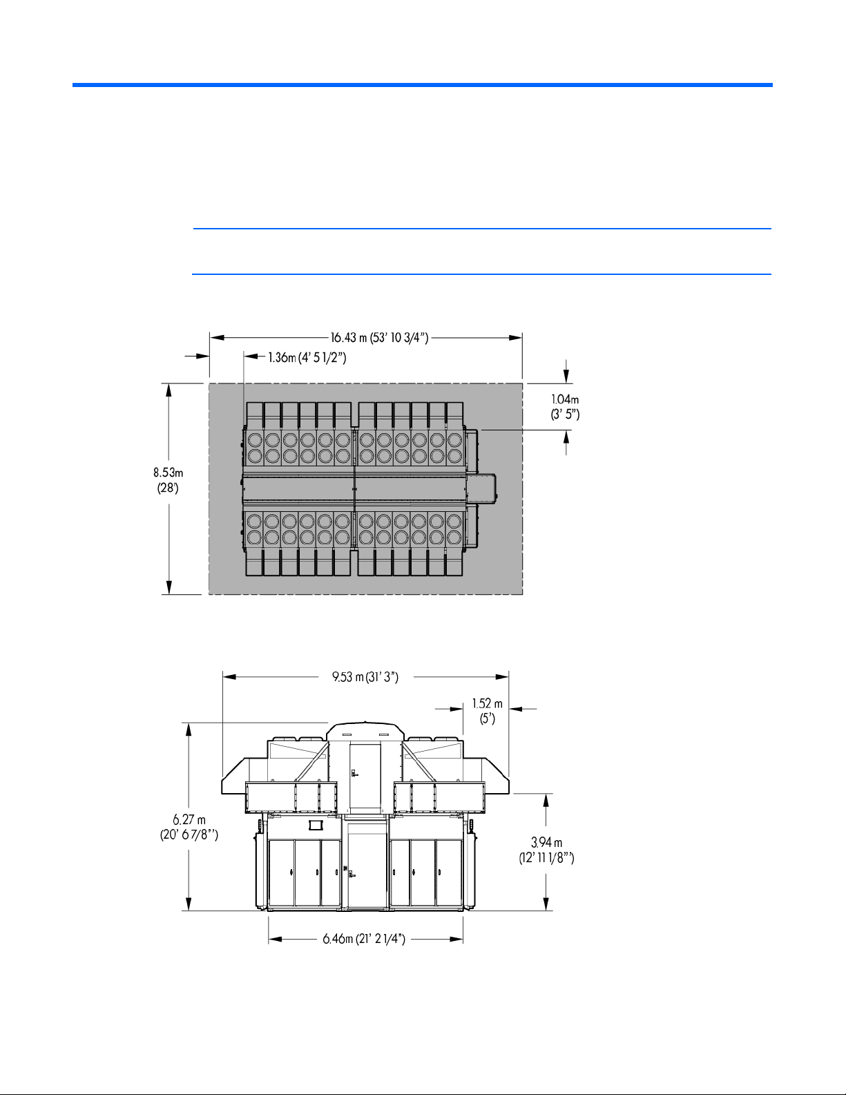
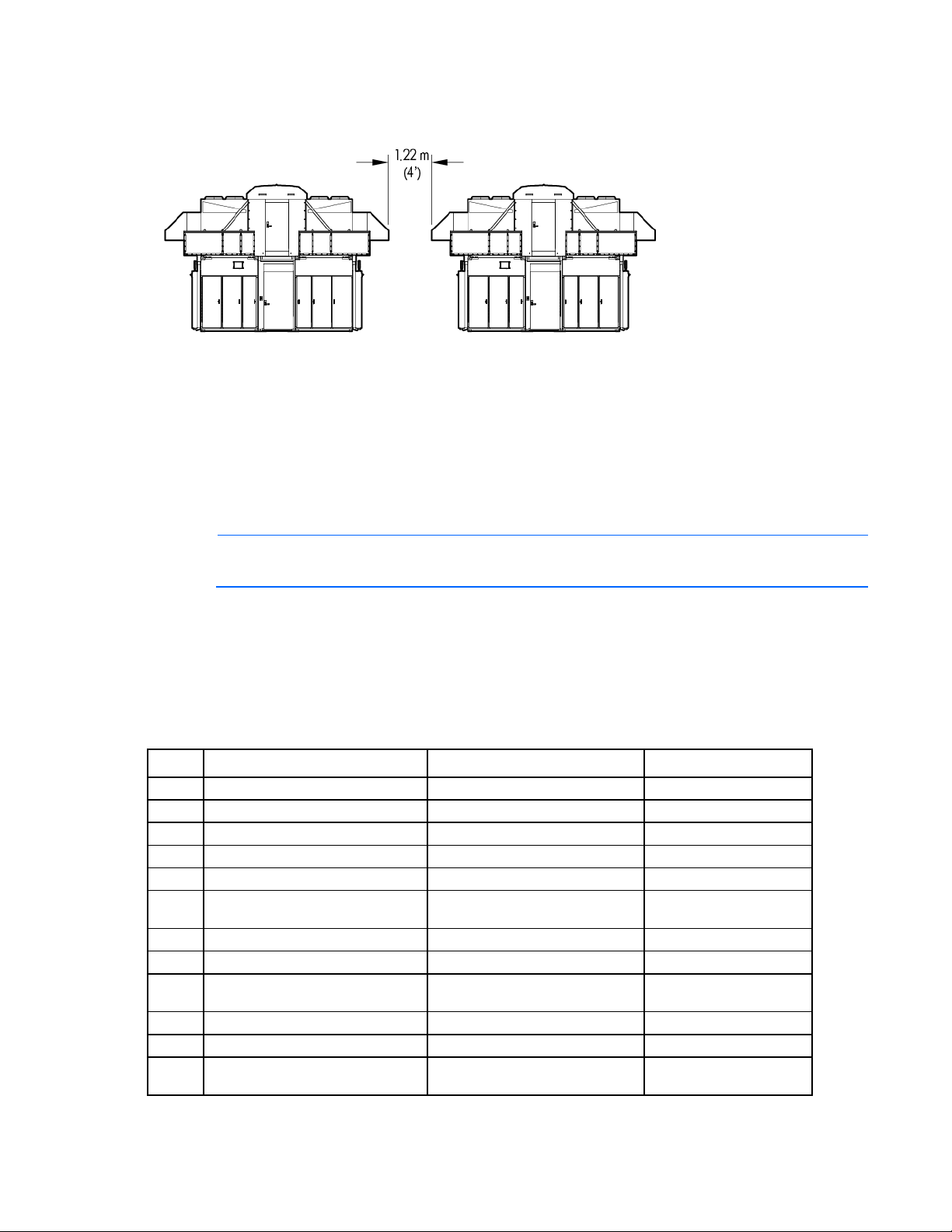
HP POD 240a dimensions and required clearances
NOTE: Shaded areas indicate required clearances.
Top view clearances shown
End 1 view clearances shown
Space requirements and clearances 8
Page 9

End 2 view clearances shown
Side view clearances shown
Space requirements and clearances 9
Page 10
End 1 view clearances shown
k
HP POD 240a weight
For information on the trucks, deliverables, and the approximate weight of the contents, see the HP POD
240a and support equipment sample offload plan (on page 10). The exact number of required trucks and the
components included on each truck might be different depending on the power redundancy in configuration.
NOTE: Allow additional space required to accommodate any additional equipment that is to be
HP POD 240a and support equipment sample offload plan
This is a sample of trucks and weights for the HP POD 240a structure and equipment that is delivered to the
customer site. Each offload plan will vary based on the components purchased, the configuration of the HP
POD 240a (redundant and non-redundant). The exact number of required trucks and components included
on each truck may differ based on the specific customer POD solution.
Truck* Contents Comments Truck weight (lbs)
1
2
3
4
5
6a
6b
7
8a
8b
9
10
installed, such as a generator or UPS.
Generator enclosure P1 Optional
Fuel tank for Generator-P1 —
Generator enclosure P2 Optional
Fuel tank for Generator-P2 —
UPS enclosure A1 Optional
IT section A without IT installed
IT section A with IT installed —
Hot aisle Includes fans and catwal
IT section B without IT installed
IT section B with IT installed —
UPS enclosure B1 Optional
HVAC/DX cradles 1 and 2 Each with 12 HVAC/DX and a
Includes racks, PDUs, and
dropboxes, but has no IT installed.
Includes racks, PDUs, and
dropboxes, but has no IT installed.
catwalk
57,935
29,455
57,935
29,455
62,895
50,000
93,000
23,000
50,000
93,000
62,895
18,000 per cradle
Space requirements and clearances 10
Page 11

Truck* Contents Comments Truck weight (lbs)
11
12
13
14
HVAC/DX cradles 3 and 4 Each with 12 HVAC/DX and a
catwalk
Canopy and end walls Creates the service area
HP POD 240a electrical pull boxes For electrical service entry
Misc. parts and pieces Gutter assembly, condensation,
piping, and hardware
18,000 per cradle
8,100
875
1,000
*The truck number does not reflect the actual order of the trucks arrival.
Site space and clearance requirements
The selected site for the HP POD 240a must be large enough to install, service, maintain, and potentially
upgrade the unit and its payload.
Here are two examples for site clearances:
If the HP POD 240a is to be installed in a warehouse, ensure that the warehouse doors are large
enough to accommodate it.
If the HP POD 240a is to be installed outdoors, ensure there is adequate clearance for all buildings,
utility lines, or other site structures, such as gates and headers.
Every site must have sufficient clearance for assembly, maintenance, and service, such as handling devices
such as a forklift, scissor lift, boom lift, or crane.
Adequate space around the HP POD 240a is necessary for airflow and cooling purposes. For specific space
requirements, see HP POD 240a dimensions and required clearances (on page 8).
Additional equipment space requirements
Allow additional space required to accommodate any additional equipment that is to be installed, such as a
generator or UPS.
Future expansions
When selecting a site location, consider future space and accessibility requirements. Adequate space
around the HP POD 240a is necessary for airflow and cooling purposes. When locating additional
equipment in close proximity of the HP POD 240a, for example, additional HVAC/DX, generators, and UPS
devices, consult with HP for site locations.
For specific space requirements, see the HP POD 240a dimensions and required clearances (on page 8).
Space requirements and clearances 11
Page 12

Preparing for delivery and assembly
Shipping considerations
The HP POD 240a is packaged for shipping such that exposure to weather does not result in damage
to the components.
The HP POD 240a is shipped on air-ride trailers to avoid vibrations during shipment.
The HP POD 240a components are shipped based on the assembly plan and available space at the
customer site.
Depending on the site location, additional restrictions and permits might be required, which can effect
Suggested assembly installation equipment
the delivery time line.
Crane (2)
Forklift (1)
Scissor lift (2)
Boom lift (1)
Temporary flood light towers (2)
Fuel spill containment kit
Portable generator
Safety for assembly
National, state, regional, and local safety regulations must be enforced at all times to prevent work-related
injuries. Before installation, HP recommends reviewing the following OSHA safety sections:
Equipment safety—Crane, forklift, scissor-lift, boom-lift, and tools
Traffic safety
Assembly and personnel safety
Electrical safety
Fuel spill containment safety
PPE and head protection
All contractors must adhere to OSHA requirements for the use of PPE to reduce employee exposure to
hazards. The construction area around the HP POD 240a construction site is a required hard-hat area, and
all personnel who enters the construction site must wear a hard hat, safety vest, and any additional OSHA,
HP, and customer required PPE.
Preparing for delivery and assembly 12
Page 13

Temporary lighting and power
Proper temporary lighting and power must be installed and maintained in all construction work areas.
When using temporary lighting:
Label panels and breakers that are used for temporary lighting and power.
The location of panels must be shown on the construction site plan and posted at the entrance to work
area.
Lamps for general illumination must be protected from breakage, and metal shell sockets must be
grounded.
Temporary lights must not be suspended by cords, unless they are so designed.
Storage requirements
CAUTION: The HP POD 240a must maintain 20% relative humidity to minimize condensation
Changes in ambient temperatures cause cond ensat ion in a HP POD 240a t hat is n ot oper ating. If the HP POD
240a is placed in storage or is non-operating mode for over 72 hours, HP recommends using one of the
following methods to minimize condensation and oxidation within the HP POD 240a:
and oxidation within the HP POD 240a.
Dessicant unit
Dessicant material
Heater with a fan
Air conditioner with heater strip
Consult with HP Services to determine the most effective method.
Assembly prerequisites
Before installing the HP POD 240a, verify that the following prerequisites have been met:
All components have been delivered to the facility.
The HP POD 240a and power distribution components are in final location.
Facility power, water, and drainage are at the final location.
Provisions for properly grounding the HP POD 240a have been made.
There are required clearances, including overhead
Coordination of all trade personnel required for assembly
Completed Job Safety Analysis
Required PPE and head protection (on page 12) for all personnel is available
Preparing for delivery and assembly 13
Page 14

Environmental considerations
Environmental considerations
Avoid placing the HP POD 240a directly along a drainage path or in an area prone to flooding.
Verify that the HP POD 240a is properly grounded in accordance with NFPA 70 in accordance with
Cold weather
NEC (NA) and IEC (EMEA and APJ).
The HP POD 240a requires a water supply and several water drains. Extreme cold weather might cause
damage to the supply and drain lines. Evaluate the following for additional cold weather protection:
Regional location of HP POD 240a
Exposure of supply and drain lines to extreme cold temperature
Extreme cold weather can affect crane and lifting operations. When temperatures drop below 10°F,
appropriate consideration must be made with respect to shock loading, crane hydraulics, and possible
derating of the crane.
Areas prone to lightning or power surges
The HP POD 240a structure and internal components are all bonded together. A common Grounding
Electrode Conductor Connection point is provided. Properly bonding and grounding of the HP POD 240a
minimizes the effects of a lightning strike. A TVSS device is provided on the HP POD 240a input connection
to protect the HP POD 240a electrical system from voltage transients. If your site is in an area that is subject
to frequent lightning strikes, the HP POD 240a must be protected in accordance with NFPA 780/NEC (NA)
and IEC (EMEA and APJ). HP recommends that you contact a certified lightning protection consultant.
Seismic activity
If your site is in an area that has frequent seismic activity, HP recommends that you contact a seismic activity
consultant. If your site is in an area that has high vibration level, HP recommends that you contact a vibration
isolation consultant. There are no provisions for anchoring the HP POD 240a.
Environmental considerations 14
Page 15

Utilities
Proximity to utilities and drains
Consider proximity to required utilities, such as power, water, and network connections. While required
utilities can be brought to nearly any selected site, there is a potential for increased costs and decreased
efficiency when the HP POD 240a is located further from the utility source.
For utility clearance information, see HP POD 240a dimensions and required clearances (on page 8).
System utilities
The site location must accommodate the following utilities:
Water supply (on page 15)
Drainage (on page 16)
Water supply
Power (on page 17)
The HP POD 240a requires supply water for the humidifier. The supply water must meet the following
requirements:
Requirement Specification
Pressure
Temperature
Instant flow-rate
Connection
Hardness
Conductivity
Organic compounds
Do not treat the water with softeners, because softeners might produce foam, which affects the
operation of the unit.
between 0.1 and 0.8 MPa (1 and
8 bars)
between 1 and 40 °C
no lower than the rated flow of the
fill solenoid valve
G3/4M
no greater than 40°fH (equal to
400 ppm of CaCO3)
125 to 1250 μS/cm
None
Do not use well water, industrial water, water from cooling circuits, or water contaminated by any
chemicals or bacteria.
Do not add disinfectants or anti-corrosive compounds to the water, which are potential irritants.
For additional dimensions, see the HP Site Preparation Drawing Package (on page 6).
Utilities 15
Page 16

Water quality
Water must be maintained per the following acceptable water quality standards.
Requirement Specification
Type of water introduced
Instant water fill flow-rate
Drinking water
Do not use demin or softened water.
0.6 l/min 0.16 gpm
If your water is out of range, consult a water quality expert.
Drainage
The following figure illustrates the drain locations on the HP POD 240a.
Side view shown
Callout Component Description Quantity per
side
Total quantity
per HP POD
240a
1
Condensate drain Removes condensation and water
2
from the HP POD 240a exterior.
2
Humidifier drain Removes excess water pulled from the
1
interior of the HP POD 240a by the
humidifier.
3
Rain water drain Removes rain water from the HP POD
2
240a
4
2
4
Utilities 16
Page 17

Power
IMPORTANT: To provide power to the HP POD 240a, external transformers and switchboards
may be required. This equipment must be designed and installed to adhere with local, state, and
national codes, and installed by contractors with licensing required by the local jurisdiction;
For all site preparation drawings, see the HP Site Preparation Drawing Package (on page 6) included on the
documentation CD.
Power requirements
The HP POD 240a can be installed as a single source 1N load by providing all required feeders from one
common power sources and from common switchboards and transformers, if required. A fully redundant 2N
installation can be achieved by feeding the parallel power paths from independent power sources,
switchboards and transformers if required.
Power feeder requirements:
Feature Specification
Enclosure rating
Mechanical power for
cooling system
components
Critical power for IT
equipment
city, township, and state.
IMPORTANT: All 3-phase WYE feeders for the HP POD 240a require that the neutrals and the
equipment grounding conductors remain isolated. Bonding of the two conductors is allowed at
the power source only.
NEMA 3R
4 x 300A feeders at 480VΔ, 3-phase, 3-wire, with
equipment ground conductor
2 x 3" conduit fittings per feeder provided
4 x 1000A feeders at 415Y/240V, 3-phase, 4-wire,
with equipment ground conductors
4 x 4" conduit fittings per feeder provided
Total critical power
required for HP POD
240a full capacity
External power source
When determining the final location of the power connections, consider the following:
Distance between the facility utilities and the location of the transformer and switchboard
Distance between the transformer and switchboard and the HP POD 240a
Distance between the UPS/Generator locations and the HP POD 240a switchboard
Requirements for routing electrical feeders (underground or overhead)
The facility power connection must be installed in compliance with local electrical codes and regulations. HP
reference electrical installation design is based on a maximum distance of 15.2 m (50 ft) or line of sight
between the switchboard and the HP POD 240a.
2N Redundant—1.2 MVA
Non-redundant—2.4 MVA
Utilities 17
Page 18

Transformers and switchboards
The input power for the Critical IT Loads requires a source of 380-415V, 3phase Wye power. This may
require custom transformer(s) be provided to derive this power if it does not already exist at the source. In
addition to the overall loading and KVA size, considerations should be given to the Harmonic Content of the
installation when specifying the K-Factor of the transformer(s). Alternatively, Harmonic Mitigating
Transformers might be used to passively cancel the harmonics generated by the IT Equipment.
HP offers several powerhouse solutions that include automatic transfer switching, UPS backup, transformers
and output distribution switchboards to supply your power needs.
On-site connections may include:
Main facility power to the primary side of the transformer
Transformer to the switchboard
Switchboard assembly to the HP POD 240a
For connection information, see the HP Site Preparation Drawing Package (on page 6).
Preparing the site for power
The customer must provide and submit the following fully coordinated drawings showing the exact
routing, plan view, sections, and elevations, for approval before beginning site preparation:
o Coordinated underground conduit routing drawings
o Site pad drawings
The HP POD 240a requires an external transformer and switchboard. If the customer provides their own
transformer and switchboard, they must also provide HP with the engineering drawings.
IMPORTANT: To provide power to the HP POD 240a, external transformers and switchboards
may be required. This equipment must be designed and installed to adhere with local, state, and
national codes, and installed by contractors with licensing required by the local jurisdiction;
city, township, and state.
Utilities 18
Page 19

Required facility connections
Connections to central facility infrastructure
The HP POD 240a is designed to function standalone but may be connected to existing facility systems with
additional engineering and costs.
HP POD 240a Environmental Control System
o Operational status
o Power consumption
o Environmental status
Life safety systems
o EPO
o Fire detection
o Fire suppression
Site communication
o Phone
o Security
Networking
o IT connections
Network connections
Connection portals
For information on the network connections, see the HP POD 240a Networking Guide.
The networking and connection portals are located on the cargo-end of the HP POD 240a. There are eight
portals per IT section, and each of the different sized portals are used for different connections.
Required facility connections 19
Page 20

End view shown
4
Connection portal
Connection point Quantity per IT
diameter
3-inch portal
1.5-inch portal
Networking connection for all IT
Communication connection for all
communication
ECS
EPO
Fire alarm
Phone
1.5-inch portal
(Optional) vestibule communication
connections
NOTE: The connection portal location and configuration might look different, depending on the
HP POD 240a model.
Grounding requirements
The HP POD 240a structure and internal components are all bonded together. A common Grounding
Electrode Conductor Connection point is provided.
WARNING: To avoid the risk of personal injury or electric shock, the HP POD 240a must be
properly grounded, and each of the individual sections must be bonded together in accordance
Grounding and bonding of the HP POD 240a must comply with Article 250 of the NFPA 70 in
with NFPA 70 in accordance with NEC (NA) and IEC (EMEA and APJ).
CAUTION: You must remove any painted surface from all grounding surfaces. Failure to do so
results in an ineffective ground.
accordance with NEC (NA) and IEC (EMEA and APJ).
section
2
2
Total quantity per
HP POD 240a
8
4
4
Required facility connections 20
Page 21

The HP POD 240a structural sections, metal raceways, wireways, conduit, boxes, and other external
intersystem components must be bonded with grounding conductors per NFPA 70 in accordance with
NEC (NA) and IEC (EMEA and APJ).
Bonding of Piping Systems and Exposed Structural Steel must comply with NF PA 70 in accordance with
NEC (NA) and IEC (EMEA and APJ).
Feature Specification
Grounding pad
A grounding pad is located on the underside of the HP POD 240a at the outside
corner of each IT section, under the electrical panel.
Grounding pads are located inside the HP POD 240a at ceiling level to bond the
sections together and bond the IT racks.
Grounding lugs
Grounding lugs cannot be attached to any painted surface.
Grounding lugs must be compression-type 2-hole lug
Ground rod system or
ground well
IMPORTANT: Before installing the HP POD 240a, consult your local AHJ for applicable codes
Customer must provide an effective grounding system with ground rod or ground well.
and to review site-specific location guidelines. If needed, obtain any necessary permits.
The grounding electrode conductor connections are located on IT sections A and B of the HP POD 240a.The
following figure shows the location for one of the IT sections.
Side view shown
Required facility connections 21
Page 22

End view shown
Item Component
1
Grounding electrode conductor connection
Required facility connections 22
Page 23

Supported facility connections
Humidifier
A dedicated water supply and approved drainage is required for the humidifier. For more information about
the humidifier, see the HP Performance Optimized Datacenter (POD) 240a Operation and Maintenance
Manual provided with the HP POD 240a.
End view shown
Item Component
1
2
Humidifier drain and water supply on IT section A
Humidifier drain and water supply on IT section B
NOTE: Confirm with AHJ that condensate water and rain water can be mixed in the same
drainage.
Supported facility connections 23
Page 24

HP POD 240a security
A
The HP POD 240a is equipped with standard key lock hardware at each personnel entry door and six
external electrical cabinets. Each personnel entry door includes a door access contact that can be connected
to the customer facility security system. Conduit and junction boxes are provided for customer installed
controlled access systems.
Additional options for controlled access security includes:
Electronic card reader
12-digit security code keypad
Magnetic lock on each entry door
Fire, safety, and security notifications
Dry contacts are provided to enable the connection between the HP POD 240a fire alarm system and the
customer facility fire system. If the HP POD 240a is connected to the customer facility systems, then the HP
POD 240a-initiated alarms, notify the facility systems.
The customer must provide an independent connection for each system listed in the following table.
Alarm Meaning
Fire prevention alarm
Fire suppression
system (optional)
Security
EPO
The electrical layout of the fire alarm system is as described in the schematic drawing that is supplied with the
HP Performance Optimized Datacenter (POD) 240a Operations and Maintenance Manual.
Smoke has been detected in the HP POD 240a.
The suppression system alarm has been activated, and
gas will be dispersed to suppress a fire.
security breach has occurred.
The EPO system has been activated by an EPO button
or thermal event, and shut down the HP POD 240a.
Supported facility connections 24
Page 25

Glossary
AHJ
Authority Having Jurisdiction
door
A hinged portion of an enclosure that covers an opening.
DX
direct expansion
ECS
environmental control system
EPO
emergency power off
equipment
A general term, including fittings, devices, appliances, luminaires, apparatus, machinery, and the like used
as a part of, or in connection with, a modular data center. (Source: NEC.)
HVAC
Heating, Ventilation, and Air Conditioning
IEC
International Electrotechnical Commission
ISO
International Organization for Standardization
labeled
Equipment or materials to which has been attached a label, symbol, or other identifying mark of an
organization that is acceptable to the authority having jurisdiction and concerned with product evaluation,
that maintains periodic inspection of production of labeled equipment or materials, and by whose labeling
the manufacturer indicates compliance with appropriate standards or performance in a specified manner.
(Source: NEC.)
Glossary 25
Page 26

listed
Equipment, materials, or services included in a list published by an organization that is acceptable to the
authority having jurisdiction and concerned with evaluation of products or services, that maintains periodic
inspection of production of listed equipment or materials or periodic evaluation of services, and whose listing
states that either the equipment, material, or service meets appropriate designated standards potential of not
more than 42.4 V (DC or peak) supplied by a primary battery or by an isolated secondary circuit, and where
the current capacity is limited by an overcurrent device, such as a fuse, or by the inherent capacity of the
secondary transformer or power supply, or a combination of a secondary winding and an impedance. A
circuit derived from a line-voltage circuit by connecting a resistance in series with the supply circuit to limit the
voltage and current is not identified as a low-voltage limited energy circuit. or has been tested and found
suitable for a specified purpose. (Source: NEC.)
The means for identifying listed equipment might vary for each organization concerned with product
evaluation, some of which do not recognize equipment as listed unless it is also labeled. Use of the system
employed by the listing organization allows the authority having jurisdiction to identify a listed product.
NA
North American
NEC
National Electrical Code
NFPA
National Fire Protection Association
overcurrent protection
A device designed to open a circuit when the current through it exceeds a predetermined value. The ampere
rating of the device is selected for a circuit to terminate a condition where the current exceeds the rating of
conductors and equipment due to overloads, short circuits and faults to ground.
PPE
personal protective equipment
structure
Enclosure of sufficient size to allow entry of personnel.
UL
Underwriters Laboratory
UPS
uninterruptible power system
VESDA
Very Early Smoke Detection Apparatus
Glossary 26
 Loading...