

Page 1

HP Performance Optimized Datacenter 20c
Part Number: 732010-001
Maintenance and Service Guide—China
Abstract
This guide provides maintenance and service guidance for the HP Performance Optimized Datacenter 20c (HP POD 20c).
July 2013
Edition: 1
Page 2

© Copyright 2013 Hewlett-Packard Development Company, L.P.
The information contained herein is subject to change without notice. The only warranties for HP products and services are set forth in the express
warranty statements accompanying such products and services. Nothing herein should be construed as constituting an additional warranty. HP shall
not be liable for technical or editorial errors or omissions contained herein.
Page 3

Contents
Illustrated parts catalog ................................................................................................................. 5
Structural component identification .............................................................................................................. 5
Life safety component identification ............................................................................................................. 6
Electrical power component identification ..................................................................................................... 7
Control cabinet component identification ...................................................................................................... 9
HP POD 20c racks .................................................................................................................................. 10
Aisle clearances ...................................................................................................................................... 10
Cold aisle clearance ...................................................................................................................... 10
Hot aisle clearance ........................................................................................................................ 11
Replaceable components for China models ................................................................................................. 11
Overview ................................................................................................................................... 13
Installation considerations ......................................................................................................................... 13
(Optional) Fire suppression system ............................................................................................................. 13
Removal and replacement procedures ........................................................................................... 14
Buttons ................................................................................................................................................... 14
EPO button ................................................................................................................................... 14
DIN rail components ................................................................................................................................ 15
Control relay module ..................................................................................................................... 15
Differential pressure sensor ............................................................................................................. 16
Door position devices .............................................................................................................................. 18
Magnetic contacts ......................................................................................................................... 18
Electrical ................................................................................................................................................ 19
Busway drop box .......................................................................................................................... 19
Fans ...................................................................................................................................................... 22
IT cooling fan ................................................................................................................................ 22
Ventilation fan ............................................................................................................................... 24
Filters ..................................................................................................................................................... 26
Heat exchanger air filters ............................................................................................................... 26
VESDA filter .................................................................................................................................. 27
Rittal SK 3326 ventilation fan filter ................................................................................................... 28
Indicators ............................................................................................................................................... 30
ECS touchscreen and EPO indicators ............................................................................................... 30
Lights ..................................................................................................................................................... 32
LED light ....................................................................................................................................... 32
Sensors .................................................................................................................................................. 33
Heat exchanger condensate drain pan sensors .................................................................................. 33
Chilled water supply and return header drain pan sensors .................................................................. 34
Humidistat .................................................................................................................................... 35
Humidity sensor ............................................................................................................................. 37
Chilled water system temperature sensor .......................................................................................... 39
Chilled water temperature sensor internal components ........................................................................ 40
Temperature sensor (cold aisle) ....................................................................................................... 43
Temperature sensors (hot aisle) ........................................................................................................ 44
Fluid system components .......................................................................................................................... 45
Chilled water supply and return header pressure sensors .................................................................... 45
Contents 3
Page 4

Chilled water flow sensor ............................................................................................................... 47
Chilled water system temperature sensor .......................................................................................... 48
Chilled water temperature sensor internal components ........................................................................ 49
Heat exchanger ............................................................................................................................ 51
Humidifier .................................................................................................................................... 52
Humidistat (if installed) ................................................................................................................... 56
Valves.................................................................................................................................................... 58
External chilled water isolation valve ................................................................................................ 58
External pressure gauge isolation valve ............................................................................................ 59
Periodic maintenance .................................................................................................................. 61
Periodic maintenance overview ................................................................................................................. 61
Qualified personnel ................................................................................................................................. 61
Cooling system ....................................................................................................................................... 61
Leak detection ............................................................................................................................... 62
Leak isolation ................................................................................................................................ 62
Humidifier (if installed) ............................................................................................................................. 63
ECS ....................................................................................................................................................... 64
Electrical ................................................................................................................................................ 64
Fire alarm and suppression system ............................................................................................................ 66
HP POD 20c structure .............................................................................................................................. 66
Life safety ............................................................................................................................................... 67
Access control ......................................................................................................................................... 68
Third-party components ............................................................................................................................ 68
Specifications ............................................................................................................................. 69
General HP POD 20c specifications .......................................................................................................... 69
Electrical specifications .................................................................................................................. 69
Water specifications ...................................................................................................................... 70
Rack specifications .................................................................................................................................. 70
Thermal and air flow performance ............................................................................................................. 70
Environmental specifications ..................................................................................................................... 70
Optional features specifications................................................................................................................. 71
Contacting HP ............................................................................................................................ 72
Before you contact HP .............................................................................................................................. 72
HP contact information ................................................................................................................... 72
Regulatory information ................................................................................................................ 73
HP POD 20c regulatory compliance .......................................................................................................... 73
Safety and NEC compliance ........................................................................................................... 73
Regulatory requirements for EXIT signs ....................................................................................................... 74
Safety and regulatory compliance ............................................................................................................. 75
Warranty information .............................................................................................................................. 75
HP POD 20c regulatory compliance .......................................................................................................... 75
Glossary .................................................................................................................................... 76
Documentation feedback ................................................................
............................................. 78
Index ......................................................................................................................................... 79
Contents 4
Page 5
Illustrated parts catalog
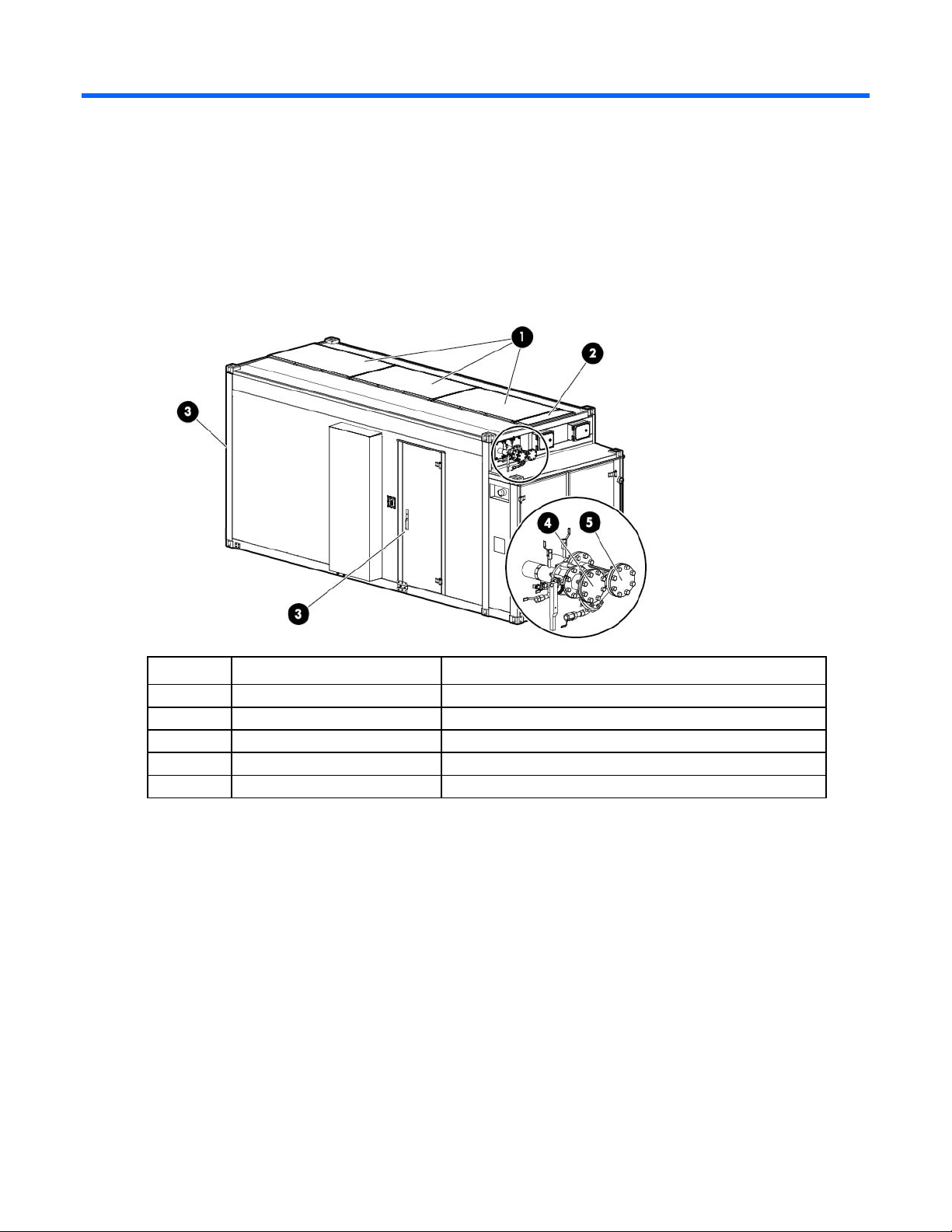
Structural component identification
The HP POD 20c documentation frequently refers to the specific components of the HP POD 20c as shown
in the following figure and described in the following table.
Item Component Description
1
2
3
4
5
Heat exchanger access hatches Provides access to the overhead heat exchangers
Power busway access hatch Allows access to the power busway end feed boxes
Personnel access doors Provides access to the POD
Facility chilled water return Facilitates the return of chilled water to the POD
Facility chilled water supply Facilitates the supply of chilled water to the POD
Illustrated parts catalog 5
Page 6
Life safety component identification
EPO alarm
Indicates the initiation of the EPO system with an audible alarm
Item Component Description
1
2
3
4
5
6
7
8
9
*This is an optional component that might not be included.
Exit sign locations Indicates the location of an exit
EPO strobe Red—An EPO event occurred and the HP POD 20c shut down.
EPO button Enables manual initiation of the EPO system
Fire strobe light Indicates a fire alarm condition within the HP POD 20c
Fire suppression alarm Indicates the initiation of the fire suppression system with an
audible alarm
Fire alarm manual pull* Enables manual initiation of the fire system, which includes
activating the interior and exterior fire strobe lights and the
optional fire suppression system
Fire suppression abort button* Aborts the fire suppression system. A fire suppression abort
button is located next to each personnel door.
EPO button Disconnects the HP POD 20c from main power, activates the
red EPO indicator on the control cabinet door, and activates
the red EPO strobe on the HP POD 20c exterior.
To restart the HP POD 20c after an EPO event, you must reset
the EPO button by turning the key and switching the button to
the Active position.
Illustrated parts catalog 6
Page 7
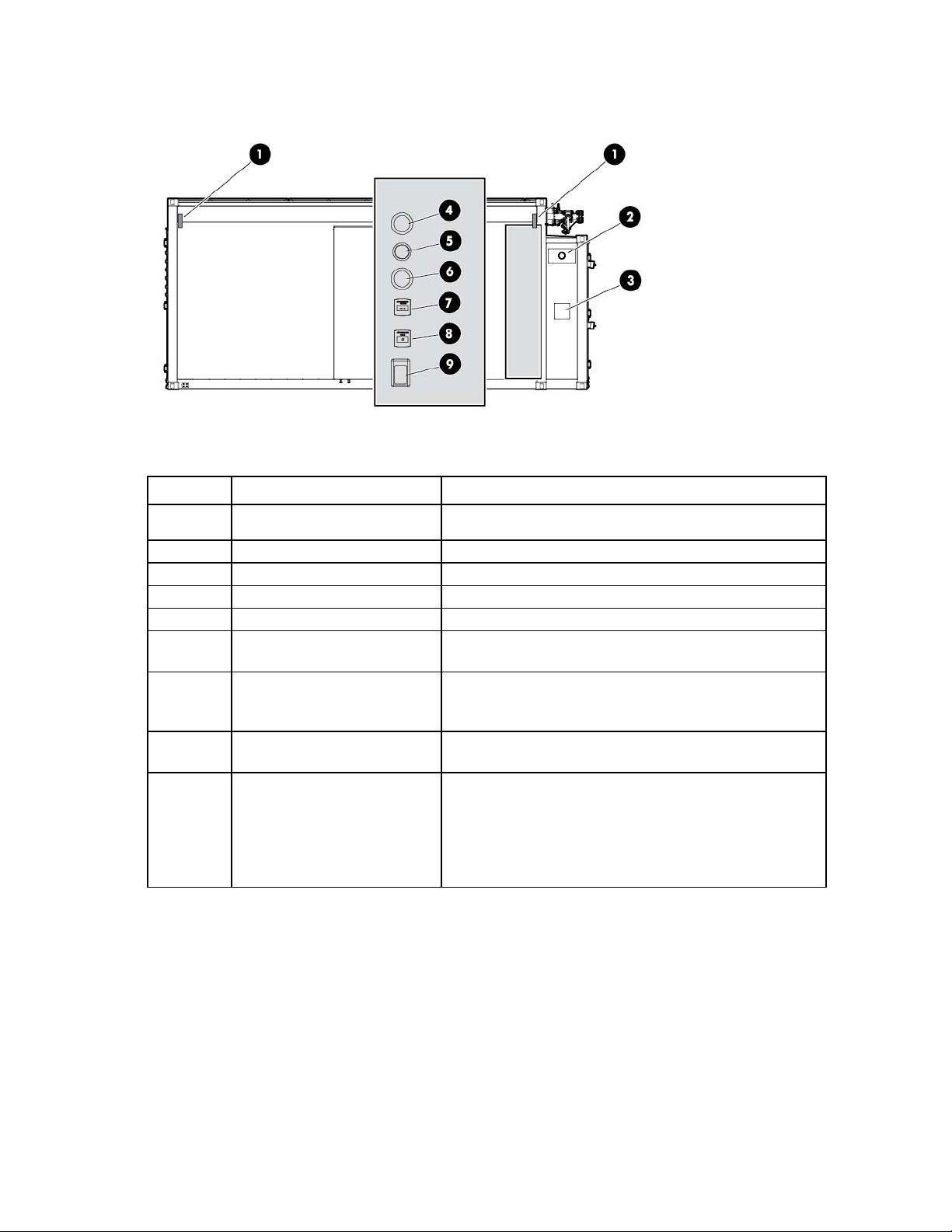
Electrical power component identification
•
•
•
Front view shown
Item Component Description
1
Demarcation box* Customer communication connection point for the following
components:
ECS
Security
Phone
2
3
*The demarcation box and the fire box are communication data points that are provided on the POD by HP. Connecting
these data points is the responsibility of the customer, unless an approved Statement of Work is initiated.
Fire box* Connection location for fire emergency and VESDAnet signals
380-415 VAC Y, 3-phase,
400 A
Feed A and B power for IT critical loads busways and house power
Main breaker locations
Side view shown
Illustrated parts catalog 7
Page 8
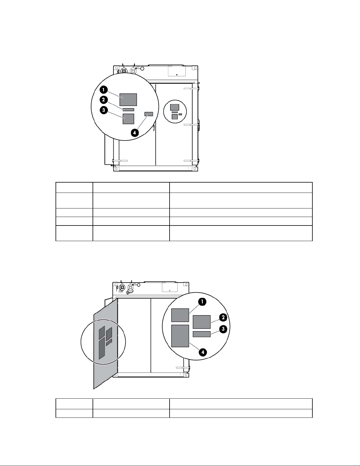
External panel labels
Front view shown
Item Electrical safety label Description
1
2
3
4
Danger sign Provides a reminder to users that the electrical panels must be
accessed only by authorized personnel
Disconnect label Provides the order for disconnecting the electrical panels
Caution Cautions users about isolating power from the HP POD 20c.
Arc flash warning Provides a reminder to users of the danger of arc flash and
required PPE
Internal panel labels
View shown
Item Electrical safety label Description
1
Input power Lists the input power information
Illustrated parts catalog 8
Page 9
Item Electrical safety label Description
•
•
•
•
•
•
•
2
3
4
Panel schedule/circuit breaker
table
Fuse type table Lists all fuse types and sizes
Wire color code Lists the 380-415 Y/200-240 V color codes:
Lists the layout and designation for all circuit breakers
Purple/Brown—Phase A/L1
Purple/Orange—Phase B/L2
Purple/Yellow—Phase 3/L3
Purple/White—Neutral
Green and yellow—Equipment ground
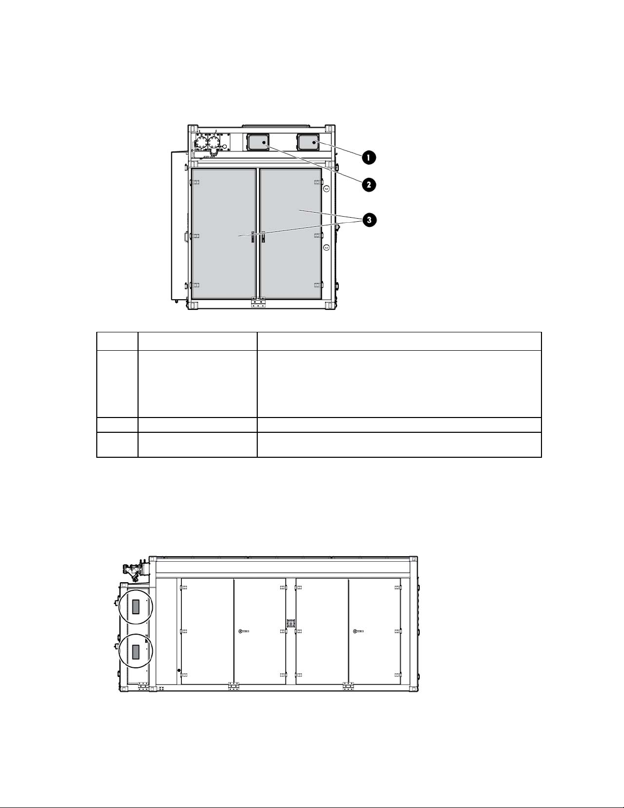
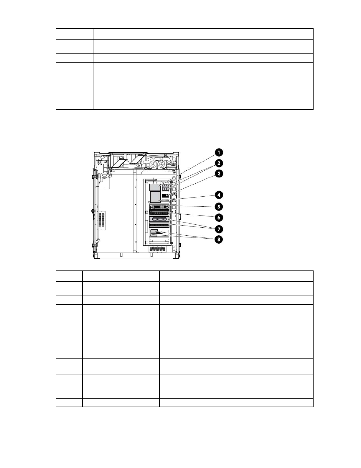
Control cabinet component identification
Item Component Description
1
2
3
4
VESDA air sampling smoke
detection unit
Leak detection relays Interprets the electronic leak signals
Fire suppression Data connection points for the fire suppression panel and input
Fire alarm and suppression
release control panel
An early warning laser scan smoke detection unit
components
Controls all fire systems within the HP POD 20c, including the
smoke detection system, fire suppression system, fire pulls, and
so on
Includes a battery backup system that provides power to the
fire system during a utility power loss
5
ECS relays and ECS modules Relays for the ECS control, ECS communications, I/O connections,
and terminal block connections
6
7
8
Fan control Fan power supply controls and relays
EPO controller board and house
panel fuses
Connections for the EPO system and fuses for other house panel
components
Battery backup power supply Provides 24V DC power to the PLC and ECS system
Illustrated parts catalog 9
Page 10
HP POD 20c racks
The HP POD 20c contains a total of ten IT racks.
CAUTION: If any racks contain empty RU space, use the HP POD 20c filler panels to maintain
the efficiency of the HP POD 20c thermal system. Filler panels are available from HP in 10-pack
quantities (part number AQ682A) and 100-pack quantities (part number AS993A).
For more information about racks and network cabling, see the HP Performance Optimized Datacenter
Networking Guide.
Aisle clearances
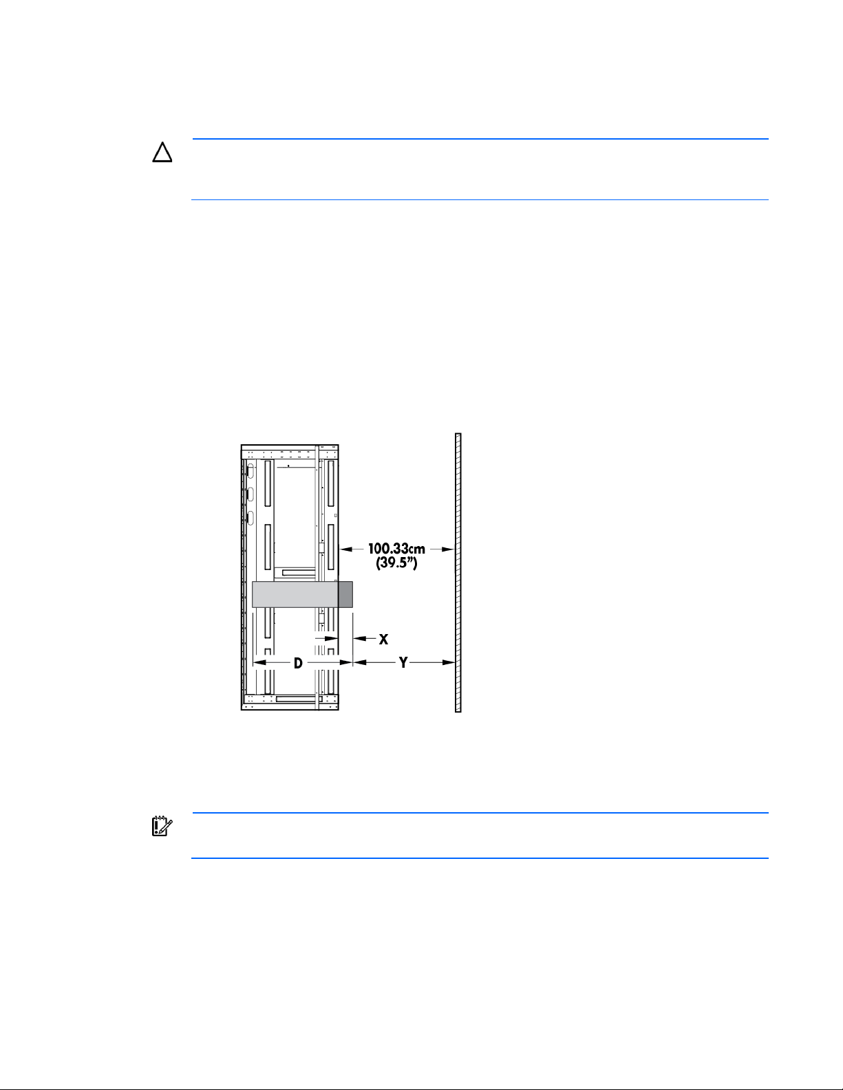
Cold aisle clearance
The maximum protrusion of any installed IT component directly impacts the available cold aisle clearance for
removal and replacement of other IT components. Maximum component depth must follow the clear aisle
distance calculations. The following figure shows how to calculate this distance.
The maximum rack face-to-cold aisle wall distance is 39.5 inches. In the figure, X represents any protrusion
into the cold aisle starting from the rack face of the installed IT component (for example, the bezel). Y
represents cold aisle clearance. The cold aisle clearance dictates the maximum depth (D) of any installed IT
component. To find the maximum cold aisle clearance, calculate 100.33 cm (39.5 in) - X = Y.
IMPORTANT: As the value for X increases, the value for Y decreases, which also decreases the
maximum depth allowed for an installed component.
Illustrated parts catalog 10
Page 11
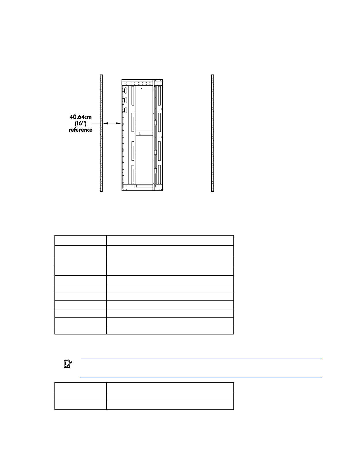
Hot aisle clearance
SPS-FILTER REPLACEMENT VESDA
A licensed electrician must connect the power according to all local and national
Hot aisle clearance is defined as the distance from the rear of the rack to the hot aisle wall. The reference
distance of 2.54 cm (16 in) must be considered when selecting IT infrastructure that will populate into the hot
aisle.
Replaceable components for China models
The replaceable components in the following table can be replaced by qualified facilities personnel.
Spare part number Description
595107-001
595108-001
612980-001
612981-001
612982-001
612983-001
637129-001
637136-001
641859-001
660819-001
The replaceable components in the following table are electrical components that must be replaced by a
certified electrician.
IMPORTANT:
electrical codes, and must comply with manufacturer specifications.
Spare part number Description
660784-001
660786-001
SPS-FILTER SCREENS FRAME w/FILTER
SPS-MAINT KIT FILTERS-AT979A
SPS-BUS BAR 5 POLE 3M
SPS-END CAP
SPS-HOUSING COUPLER
SPS-MOUNTING STUD M10
SPS-TSAT 60
SPS-SENSOR PRESSURE ABS 10 BAR
SPS-CABLE WD-CS-2M
SPS-Breaker 1SDA054578R1
SPS-Breaker Shield 1SDA054691R2
Illustrated parts catalog 11
Page 12
Spare part number Description
SPS-Relay Assembly 46.61.9.0240074
These parts must be replaced by a licensed fire safety contractor according to all
SPS-DETECTOR SMOKE VESDA VLS 214
660787-001
660788-001
660789-001
660794-001
660796-001
660802-001
660803-001
660806-001
718586-001
718588-001
The replaceable component in the following table must be replaced by a licensed fire safety contractor.
IMPORTANT:
SPS-Breaker 1SDA054870R1
SPS-Fuse-Switch SV 9344.000
SPS-Switch NH00 KTF-160
SPS-Switch 1SAM150000R1005
SPS-Terminal Cover 1SDA051415R0001
SPS-Relay Assembly 62.32.8.230.0040
SPS-Relay 1SVR630884R3300
SPS-LED LIGHT CO82
SPS-HUMIDIFIER CHF03V2001
local and regional fire codes, and in compliance with manufacturer specifications.
Spare part number Description
664746-001
Illustrated parts catalog 12
Page 13

Overview
Any additional local requirements are not covered as part of the option price or basic installation
agent release delay. The fire suppression agent release countdown will continue when the abort
Installation considerations
CAUTION: All plumbing to and from the HP POD 20c must be completed by a licensed plumber.
All wiring in and around the HP POD 20c must be completed by a licensed electrician. Failure to
comply with these instructions can impact your warranty and/or result in equipment damage.
(Optional) Fire suppression system
CAUTION: The POD fire suppression system is manufacturer designed, engineered, and
installed to comply with national standards. However, HP does not certify that the installed fire
suppression system meets all local jurisdictional requirements. Compliance with local codes is
your responsibility, and includes specific local requirements for initial and periodic inspections,
certifications, and maintenance.
and deployment services, unless specifically included in an executed Statement of Work.
WARNING: Fire suppression agents include a pre-discharge warning and evacuating system. In
the event of a fire, all protected space must be evacuated as soon as possible.
IMPORTANT: The fire suppression abort button is located next to the ECS panel and can be
pressed to interrupt the 30-second fire suppression agent release delay for an additional 30
seconds. This button interrupts the countdown, but does not reset the 30-second fire suppression
button is released until the time is exhausted and the fire suppression agent is released.
The fire suppression system contains conventional fire alarm control circuits and includes features required
for single or dual-hazard suppression release applications, including a low-toxicity agent. In the event of fire
suppression release, the suppression tanks must be refilled by a certified technician.
Overview 13
Page 14
Removal and replacement procedures
Buttons
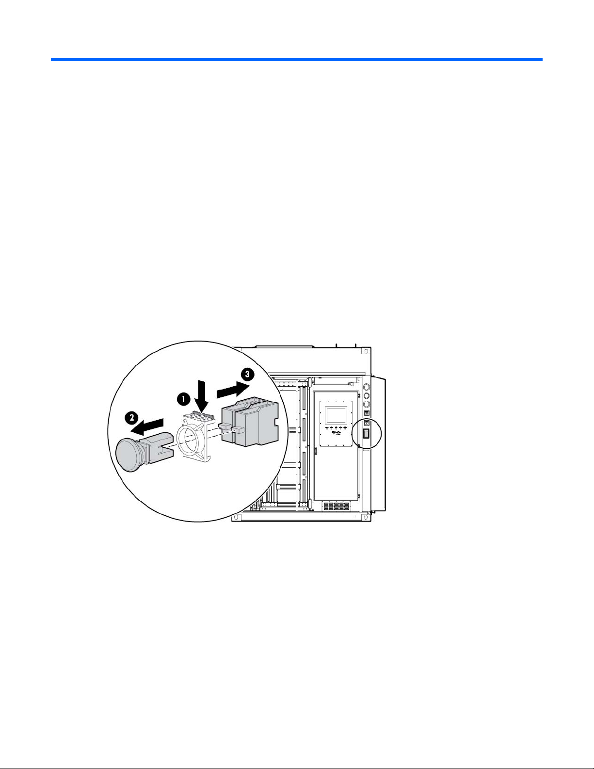
EPO button
One EPO button is located on the POD interior near the main exit. A second EPO button is located on the
Removing the EPO button
POD exterior.
1. Grasp the bracket (1).
2. Remove the EPO button from the bracket (2).
3. Remove the contact modules from the bracket (3).
4. Disconnect the wires.
Replacing the EPO button
1. Reconnect the wires.
2. Insert the button head (1) into the bracket (2).
Removal and replacement procedures 14
Page 15
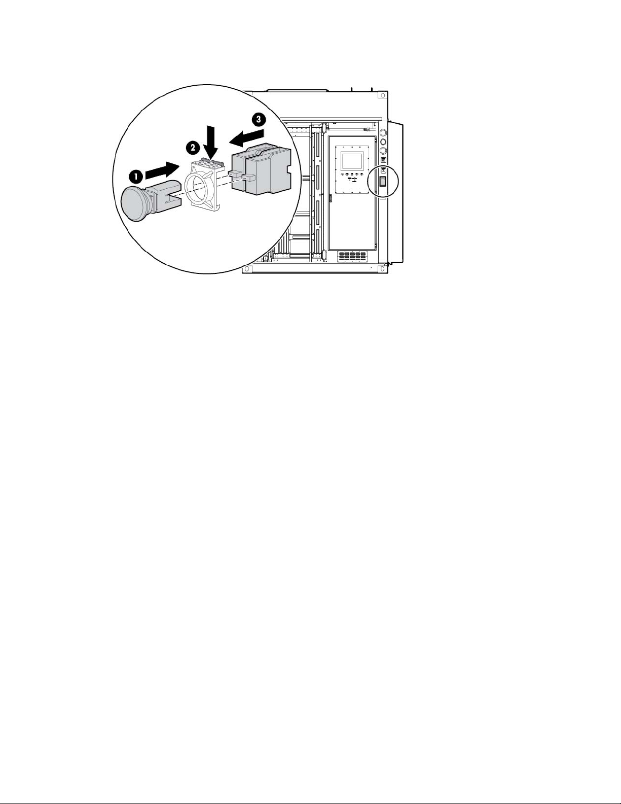
3.
Insert the contact modules (3) into the bracket (2).
DIN rail components
Control relay module
The HP POD 20c uses analog and digital control relays to communicate sensed parameters to the ECS for
overall POD control and reporting features.
Removing the control relay module
You need a screwdriver to remove and replace the control relay module.
1. Label the wired connections or take a picture to remember which wires to reconnect to the control relay
module.
2. Using a screwdriver, release the installed wiring.
3. Grasp the pull tab to disengage the control relay module from the DIN rail (1).
Removal and replacement procedures 15
Page 16
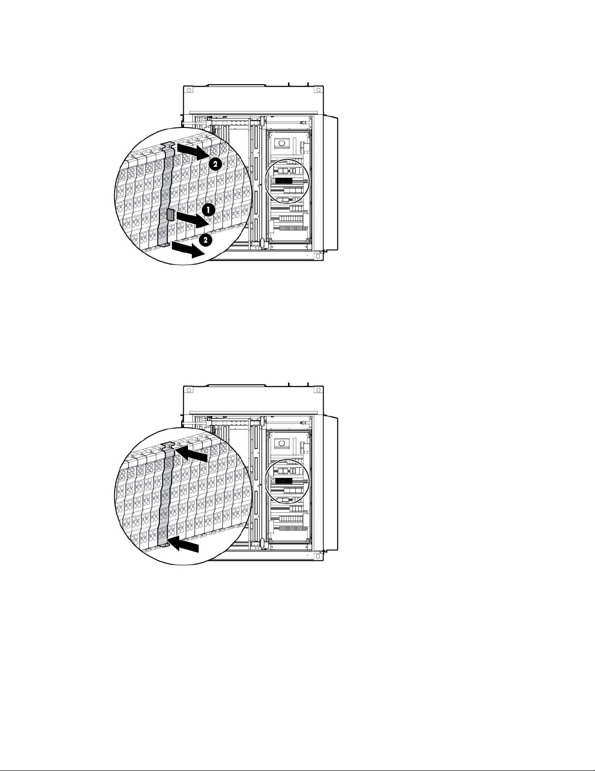
4.
Remove the control relay module (2).
Replacing the control relay module
1. Align the control relay module with the mounting and power connections.
2. Slide the module until it clicks into the DIN rail.
3. Reconnect all wiring to the control relay module.
Differential pressure sensor
The HP POD 20c uses differential pressure sensing terminals located in the ECS cabinet to take pressure
readings from the cold aisle, hot aisle, and cooling fan filters via sensing tubes. The terminal determines
cold-to-hot aisle differential pressure and filter differential pressure for all three cooling zones.
You need a small wrench to remove and replace the differential pressure sensor.
Removal and replacement procedures 16
Page 17
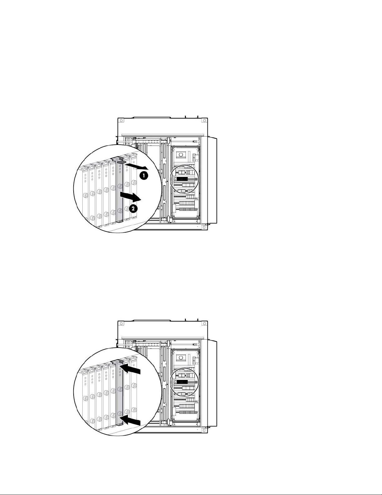
Removing the differential pressure sensor
1. Using a small wrench, loosen the tube retaining lock nut.
2. Label the hose connector tube or take a picture to remember which hose to reconnect to the I/O system
later.
3. Remove the hoses.
4. Pull the release tab at the top of the sensor to release it (1), grasp the edges of the sensor, and then pull
forward to remove it (2).
Replacing the differential pressure sensor
1. Slide the differential pressure sensor into the grooves until it clicks into place.
2. Refer to your notes on where to insert the hose to connect it to the I/O system.
3. Using a small wrench, tighten the retaining lock nut. Do not over-tighten it.
4. Reconnect the hose to the I/O system.
Removal and replacement procedures 17
Page 18
Door position devices
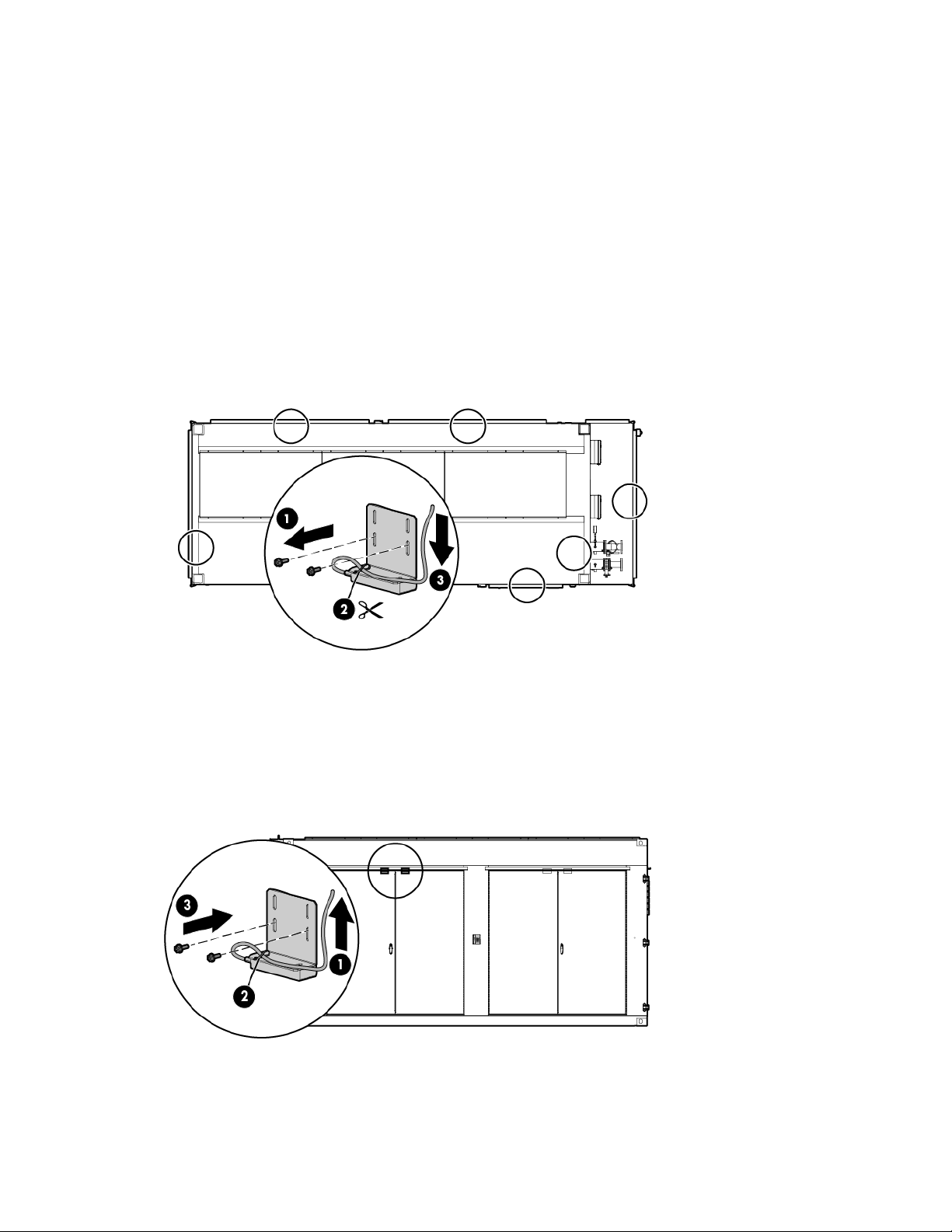
Magnetic contacts
Magnetic contacts are located on all doors and cabinets.
You need a screwdriver and scissors to remove and replace the magnetic contact.
Removing the magnetic contacts
1. Remove the two screws that secure the upper magnet (1).
2. Cut the tie wrap (2) and loosen the nut on the POD structure that secures the wire.
3. Pull the wire all the way through to the point of entry or ECS panel (3).
Replacing the magnetic contacts
1. Feed the wire all the way through from the point of entry or ECS panel (1).
2. Tighten the nut on the POD structure that secures the wire, and then replace the tie wrap (2).
3. Secure the magnet to the bracket using two screws (3).
Removal and replacement procedures 18
Page 19
Electrical
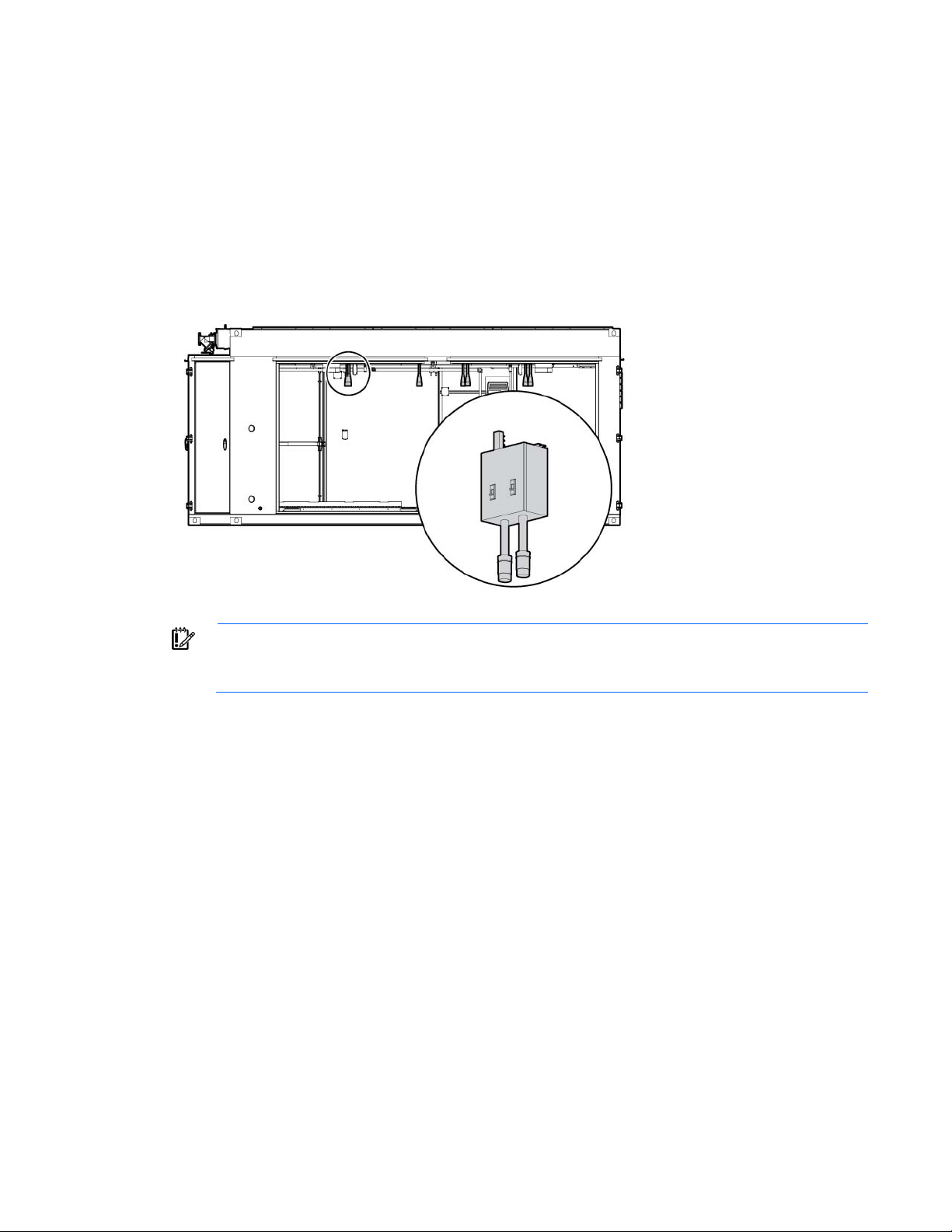
Busway drop box
The internal electrical busways provide a location to connect each of the drop boxes, which then power the
PDUs. Stagger the drop boxes on the electrical busways by connecting one drop box to busway #1 and
connecting the next drop box to busway #2. A staggered configuration enables load balancing with the rack
equipment and is necessary to ensure redundancy.
IMPORTANT: HP recommends that you shut down the associated IT equipment and de-energize
the appropriate section of the power busway before attempting to remove or replace a busway
You need a socket wrench to remove and replace the busway drop box.
drop box. The corresponding branch circuit breaker is labeled on the busway.
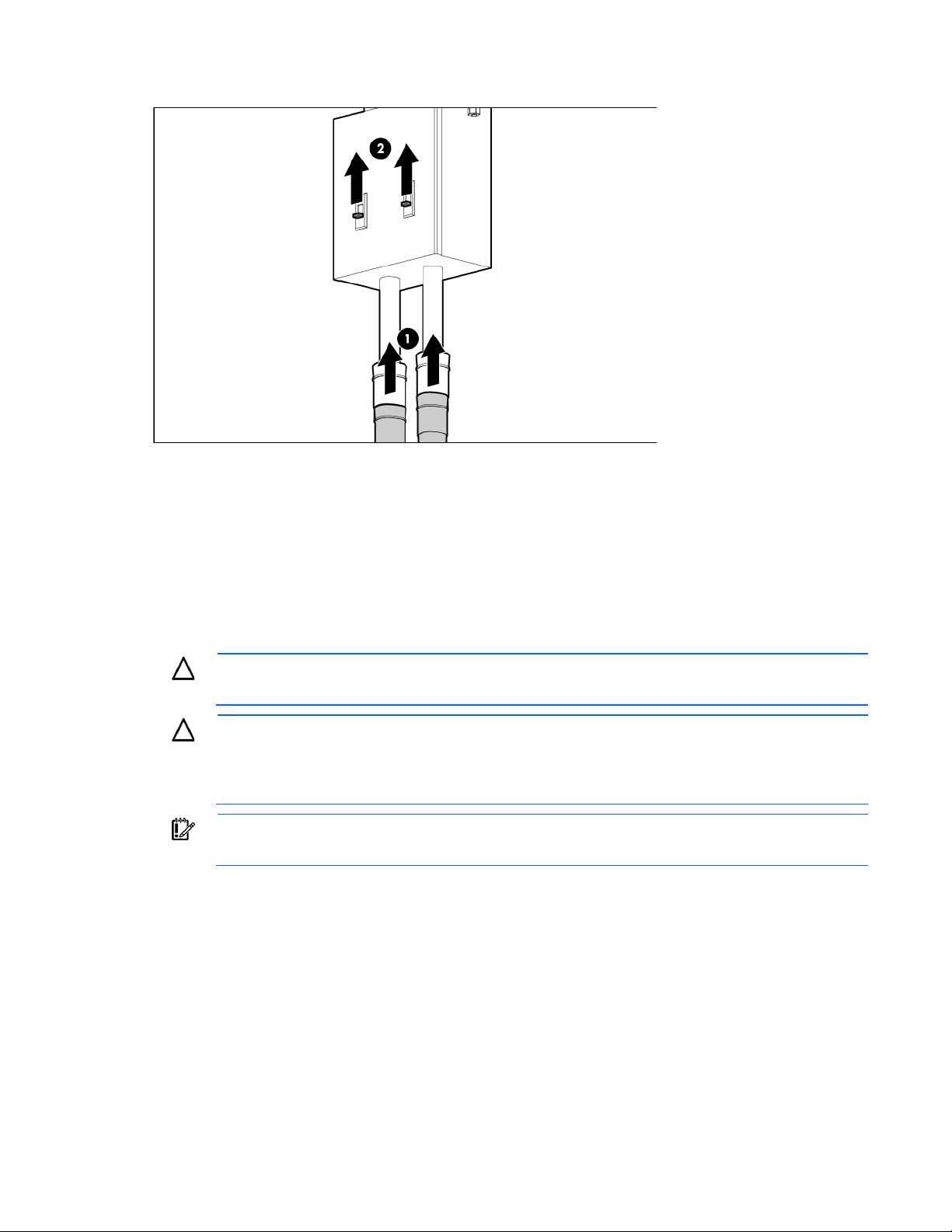
Removing the busway drop box
1. Turn the power off by opening both breakers on the busway drop box (1).
Removal and replacement procedures 19
Page 20
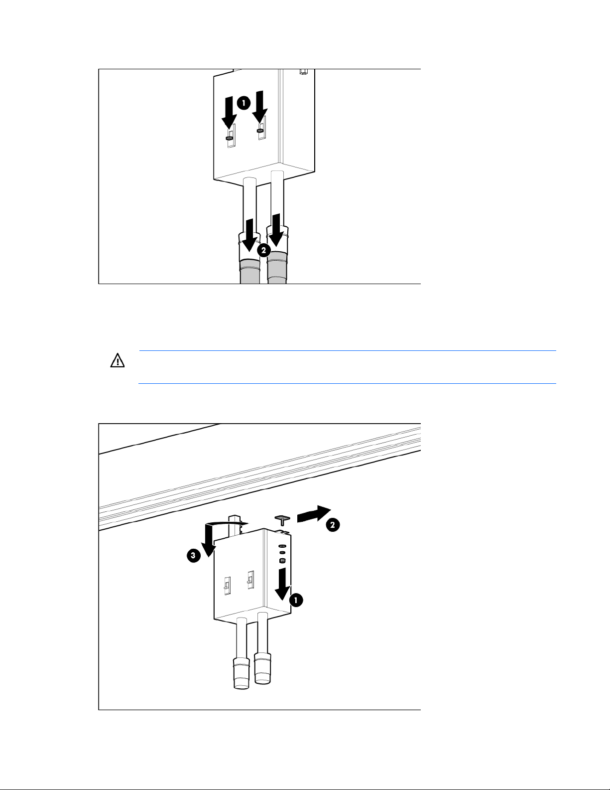
2.
Disconnect the PDUs that are connected to the busway drop box (2).
3. Use a socket wrench to loosen and remove the bolt securing the busway drop box to the retaining
hardware bracket (1).
4. Slide the hardware bracket to the right along the busway, completely disconnecting it from the busway
drop box (2).
WARNING: Use caution when removing and replacing the busway drop box. The drop box
weighs approximately 9 kg (20 lb).
5. Rotate the busway drop box 90° so that it is perpendicular to the electrical busway, and then remove
the drop box from the electrical busway (3).
Removal and replacement procedures 20
Page 21
Replacing the busway drop box
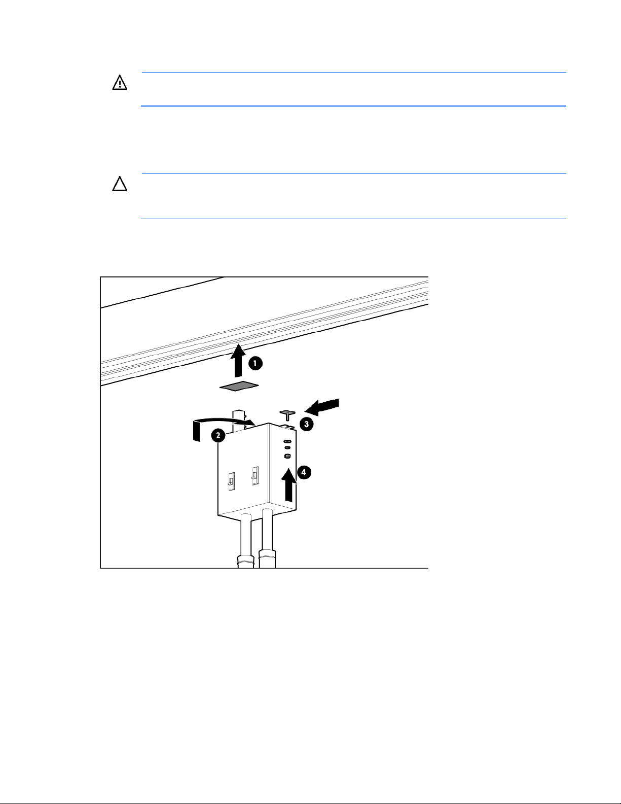
WARNING: Use caution when removing and replacing the busway drop box. The drop box
weighs approximately 9 kg (20 lb).
1. Place the silver drop box bracket onto the electrical busway where you want to replace the busway
drop box (1).
2. Note the required rotation indicated on the drop box, insert the drop box into the drop box bracket on
the electrical busway, and then rotate the drop box 90° until it locks into place (2).
CAUTION: To prevent damage to the drop box and ensure that the drop box engages properly,
be sure that the drop box is completely flush to the busway. If a drop box is damaged during
3. Slide the hardware bracket to the left along the busway until it connects to the drop box (3).
4. Secure the busway drop box to the retaining hardware bracket by using a socket wrench to insert and
installation, do not attempt to re-engage or repair the drop box.
tighten a bolt (4).
5. Connect the PDUs to the busway drop box (1).
Removal and replacement procedures 21
Page 22
6.
Power must be removed from the fan power assembly before removing or replacing
energize any additional working fans within the affected zone before replacing
energizing working fans reduces the IT cooling airflow within the zone. Take this into
Turn the power on by closing both breakers on the busway drop box (2).
Fans
IT cooling fan
HP POD 20c fans operate at four speeds to maintain the cold-to-hot aisle differential pressure and hot aisle
temperature setpoints that are programmed into the ECS.
The fan speed adjusts to maintain the programmed setpoints. Do not manually adjust the fan speed.
CAUTION:
a fan or fan bank.
CAUTION: De-
the fan. Deconsideration when deciding whether to continue operating IT equipment within the affected
zone. HP recommends powering down all of the IT in the zone.
IMPORTANT: HP recommends leaving the fans in AUTO mode during normal operation.
Removal and replacement procedures 22
Page 23

The HP POD 20c has 3 banks of 4 fans, for a total of 12 fans per zone. The fans circulate cool air from the
heat exchangers throughout the POD.
The three fan banks are located in the access hatches that are in the ceiling of the POD. The IT cooling fan
has four screws and a power connection.
You need a screwdriver to remove and replace the IT cooling fan.
Removing the IT cooling fan
HP recommends leaving the fans in AUTO mode during normal operation.
1. From the ECS panel, take manual control of the fan speed in the affected zone.
2. Set the fan speed to 0 (zero).
3. Open the access hatch door.
4. Disconnect the power harness.
5. Remove the four screws (1)
6. Remove the IT cooling fan (2).
Removal and replacement procedures 23
Page 24

Replacing the IT cooling fan
1. Position the IT cooling fan (1).
2. Replace the four screws (2).
3. Reconnect the power harness.
4. Close the access hatch door.
5. Return the fan bank to AUTO mode.
Ventilation fan
The ventilation fan is located between the ECS cabinet and the transformer cabinet. The purpose of the fan
is to provide proper ventilation to the electrical components within the ECS and electrical cabinets.
Rittal SK 3326
You need a screwdriver to remove and replace the ventilation fan.
Removal and replacement procedures 24
Page 25

Removing the Rittal SK 3326 ventilation fan
1. Open the ECS cabinet door.
2. Label and disconnect the fan wires.
3. Remove the four screws (1).
4. Pull the fan module forward to remove it (2).
Replacing the Rittal SK 3326 ventilation fan
1. Insert the fan module into the screwless spring terminal (1).
2. Rotate the fan module clockwise until it is seated (2).
3. Reconnect the fan wires.
4. Insert the ventilation fan into the ventilation fan cut-out hole.
5. Close the ECS cabinet door.
Removal and replacement procedures 25
Page 26

The Rittal SK 3326 ventilation fan has been discontinued, so if it malfunctions, you must order the Rittal SK
3243 ventilation fan.
To install the new fan, see the installation instructions included with the fan.
Filters
Heat exchanger air filters
There are two heat exchanger air filters per cooling zone for a total of six filters.
You do not need any tools to remove or replace the heat exchanger air filter.
Removing the heat exchanger air filter
1. Pull the locking tabs away from the filter to release it.
2. Pull the filter down through the frame channels to remove it.
Replacing the heat exchanger air filter
1. Angle the filter to position the top corners in the frame channels, and then push the filter up to the top of
the frame.
Removal and replacement procedures 26
Page 27

2.
Push in the bottom corners of the filter until the locking tabs engage and the filter clicks into place.
VESDA filter
The VESDA filter sensor notifies you through the ECS when a filter must be changed. HP recommends
periodically inspecting and changing each VESDA filter. A VESDA filter can be replaced during normal HP
POD 20c operation.
Removing the VESDA filter
You need a Phillips-head screwdriver for installation.
1. Remove the filter cover on the front of the VESDA unit.
Removal and replacement procedures 27
Page 28

2. Remove the 10mm screw that secures the VESDA filter (1), and then remove the filter (2).
Replacing the VESDA filter
1. Insert the new VESDA filter (1), and then replace the 10mm screw that secures the filter (2).
2. Replace the VESDA filter cover.
Rittal SK 3326 ventilation fan filter
The ventilation fan filter is located behind the louvered grille.
IMPORTANT: Check the fan filter quarterly to be sure that it is clean.
You need a screwdriver for installation.
Removal and replacement procedures 28
Page 29

Removing the Rittal SK 3326 ventilation fan filter
1. Insert a screwdriver into the bottom right corner of the louvered grille and rotate it counterclockwise (1)
to loosen the grille.
2. Grasp the louvered grille and pull forward to remove it (2).
3. Remove the old filter (3).
Replacing the Rittal SK 3326 ventilation fan filter
1. Insert the new filter (1).
2. Close the louvered grille (2).
Removal and replacement procedures 29
Page 30

Indicators
ECS touchscreen and EPO indicators
The ECS touchscreen and EPO indicators are located on the door to the control panel.
The touchscreen enables you to easily configure the environmental parameters, access data, and monitor
environmental, life safety, and access control conditions within the HP POD 20c.
The EPO indicators provide EPO status. The EPO key control and EPO reset button enable you to adjust the
EPO system mode.
Item Component Indicator Color Description
Power on indicator White Indicates the EPO power status
1
EPO shutdown indicator Red Indicates an EPO shutdown or alarm
2
EPO armed indicator White Indicates that the EPO system is armed and
3
EPO test mode indicator Yellow Indicates that the EPO system is operating
4
EPO bypassed indicator Green Indicates that the EPO shut down
5
EPO mode key control — Enables you to select the EPO mode.
6
EPO reset button — Resets the EPO system when pressed
7
EPO horn — Sounds when an EPO event occurs.
8
situation
operational
in test mode or that an EPO cover is open
functionality is bypassed
Removal and replacement procedures 30
Page 31

Removing the ECS EPO LED indicators
1. Remove the screw from the mounting base (1).
2. Remove the contact block from the mounting base (2).
3. Pull the ECS push button, selector switch, or LED light out of the mounting base (3).
Replacing the ECS EPO LED indicators
1. Insert the ECS push button, selector switch, or LED light into the mounting base (1).
2. Attach the contact block to the mounting base (2).
3. Attach the screw to the mounting base (3).
Removal and replacement procedures 31
Page 32

Lights
LED light
The HP POD 20c contains three LED lights in the cold aisle and three LED lights in the hot aisle.
You need a screwdriver to remove and replace the LED light.
Removing the LED light
You need a screwdriver to remove and replace the LED light.
1. Disconnect power from the LED light.
2. Remove the screws (1).
3. Remove the LED light assembly (2).
Replacing the LED light
1. Place the LED light where you want to secure it (1).
2. Insert the screws (2).
Removal and replacement procedures 32
Page 33

3.
Reconnect power to the LED light.
Sensors
Heat exchanger condensate drain pan sensors
The HP POD 20c - China model includes three heat exchanger condensate drain pan sensors. One drain pan
sensor is located in the drain tray below each set of the heat exchangers.
Three sensors are also located in the chilled water supply and return header drain pans, one in each of the
three sections.
When the drain pan sensor probes become wet, the normally-open circuit is closed, allowing control voltage
to return to the ECS panel and trigger the alarm.
Removing the drain pan sensor
You need a screwdriver to remove and replace the drain pan sensor.
1. Open the center fan bank in the cold aisle of the affected sensor.
2. Fully extend the fan bank door.
3. Use a flashlight to locate the sensor.
4. Follow the sensor wire to the junction box. Disconnect the wire from the junction box terminal and note
the wire location.
Removal and replacement procedures 33
Page 34

5.
Route the wire from the junction box to the sensor location, and then remove the sensor.
Replacing the drain pan sensor
1. Position the sensor in the drain pan.
2. Route the wire to the junction box and reconnect the wire.
3. Close the center fan bank in the cold aisle of the affected sensor.
Chilled water supply and return header drain pan sensors
The HP POD 20c includes three heat exchanger condensate drains. One drain pan sensor is located in the
drain tray below each set of heat exchangers.
Three sensors are also located in the chilled water supply and return header drain pans, one in each of the
Removing the chilled water supply and return header drain pan sensor
corresponding cooling zones.
1. Follow the sensor wire to the associated satellite box. Disconnect the wire from the satellite box terminal
and note the wire location.
2. Pull the wire through from the satellite box to the sensor location, and then remove the sensor.
Replacing the chilled water supply and return header drain pan sensor
1. Position the sensor in the main header drain pan.
Removal and replacement procedures 34
Page 35

2.
Route the wire to the associated zone satellite box.
3. Connect the sensor wire to the appropriate port on the satellite box terminal.
Humidistat
The humidistat is located in the cold aisle humidifier bump out.
You need a Phillips-head screwdriver and a flathead screwdriver for installation.
Removing the humidistat
1. Press the power button on the outside of the humidifier to power down the humidifier.
2. Open and danger tag the associated circuit breaker in the ECS cabinet. The circuit breakers are
identified on the panel schedule.
3. Detach the front panel of the humidistat from the mounting base:
a. Remove the screw securing the tab in the opening (1), and then slide the tab to the open position (2).
Removal and replacement procedures 35
Page 36

b.
Use a flathead screwdriver to the press the release button (1), and then pull the front panel from the
bottom to detach the panel (2). The two parts remain connected by a flat cable.
4. Squeeze the two terminal cover fins to remove the cables from the terminal block.
5. Remove the screws securing the mounting base to the wall.
Replacing the humidistat
1. Detach the front panel of the replacement humidistat from the mounting base.
a. Remove the screw securing the tab in the opening (1), and then slide the tab to the open position (2).
Removal and replacement procedures 36
Page 37

b.
Use a flathead screwdriver to the press the release button (1), and then pull the front panel from the
bottom to detach the panel (2). The two parts remain connected by a flat cable.
2. Secure the mounting base to the wall using the screws provided.
3. Squeeze the two terminal cover fins to remove the terminal covers.
4. Make the required connections by running the connection cables through the center hole in the bottom
of the mounting base and connecting the cables to the terminal block.
5. Separate the connection and control cables from the relay cables.
6. Attach the front panel.
7. Close the associated circuit breaker in the ECS cabinet.
8. Press the power button on the outside of the humidifier to power up the humidifier.
Humidity sensor
The HP POD 20c contains one humidity sensor. It is located in the cold aisle in cooling zone 2.
You need a screwdriver to remove and replace the humidity sensor.
Removal and replacement procedures 37
Page 38

Removing the humidity sensor
1. Remove the four screws that secure the sensor cover (1), and then remove the cover (2).
2. Remove the two self-tapping screws (3).
3. Identify the sensor wires.
4. Disconnect the sensor wires.
5. Remove the two retaining screws, and then remove the humidity sensor housing from the wall (4).
Replacing the humidity sensor
1. Re-attach the humidity sensor housing to the wall (1).
2. Replace the two self-tapping screws (2).
3. Reconnect the wires to the hot-aisle humidity sensor.
4. Replace the sensor cover (3).
Removal and replacement procedures 38
Page 39

5.
Replace the four screws that secure the sensor cover (4).
Chilled water system temperature sensor
The HP POD 20c contains two chilled water header temperature sensors. One is located in the chilled water
supply header and one is located in the chilled water return header.
HP highly recommends replacing sensor internal components before replacing the entire sensor. For more
information, see replacing the entire sensor.
Removing temperature sensor from the chilled water system
You need a wrench and a screwdriver to remove and replace the sensor.
1. Identify the location of the sensor to be replaced, and then remove enough header insulation to uncover
the sensor.
2. Remove the sensor cover.
3. Label and disconnect the sensor wiring.
Removal and replacement procedures 39
Page 40

4.
Rotate the immersion sleeve counterclockwise (1), and then pull forward to remove the entire sensor
from the chilled water header (2).
Replacing the temperature sensor in the chilled water system
1. Insert the new sensor probe into the chilled water header (1).
2. Rotate the immersion sleeve clockwise to secure the sensor onto the header (2).
3. Reconnect the wiring, replace the sensor cover, and replace the removed insulation.
Chilled water temperature sensor internal components
The HP POD 20c contains two chilled water header temperature sensors. One is located in the chilled water
supply header and one is located in the chilled water return header.
You need a screwdriver to remove and replace the chilled water temperature sensor internal components.
Removal and replacement procedures 40
Page 41

Removing the chilled water temperature sensor internal components
1. Remove the four screws from the sensor cover (1).
2. Remove the sensor cover (2).
3. Label and disconnect the sensor wires.
4. Remove the two screws from the chilled water temperature sensor circuit board (1).
5. Remove the chilled water temperature sensor circuit board (2).
Replacing the chilled water temperature sensor internal components
1. Replace the chilled water temperature sensor circuit board (1).
Removal and replacement procedures 41
Page 42

2.
Replace the two screws to secure the chilled water temperature sensor circuit board (2).
3. Reconnect the sensor wires.
4. Replace the four screws to secure the chilled water temperature sensor cover (2).
5. Replace the chilled water temperature sensor cover (1).
Removal and replacement procedures 42
Page 43

Temperature sensor (cold aisle)
The HP POD 20c contains three temperature sensors in the cold aisle.
You need a screwdriver and scissors to remove and replace the cold aisle temperature sensor.
Removing the cold aisle temperature sensor
1. Remove the four screws that secure the cold aisle temperature sensor cover (1), and then remove the
cover (2).
2. Label the cold aisle temperature sensor wires or take a picture to remember which wires to reconnect
later.
3. Disconnect the wires.
4. Remove the two retaining screws, and then remove the cold-aisle temperature sensor housing from the
wall.
Replacing the cold aisle temperature sensor
1. Reconnect the wires to the cold-aisle temperature sensor.
2. Reconnect the wires.
3. Re-attach the cold-aisle temperature sensor housing to the wall using the two retaining screws.
Removal and replacement procedures 43
Page 44

4.
Replace the cold-aisle temperature sensor cover (1).
5. Replace the four screws that secure the cold aisle temperature sensor cover (2).
Temperature sensors (hot aisle)
The HP POD 20c contains three temperature sensors in the hot-aisle.
You need a screwdriver to remove and replace the hot aisle temperature sensors.
Removing the hot aisle temperature sensor
1. Remove the four screws (1) that secure the hot-aisle temperature sensor cover, and then remove the
cover (2).
2. Label the hot-aisle temperature sensor wires or take a picture to remember which wires to reconnect
later.
3. Disconnect the wires.
Removal and replacement procedures 44
Page 45

4.
Remove the two retaining screws, and then remove the hot-aisle temperature sensor housing from the
wall.
Replacing the hot aisle temperature sensor
1. Reconnect the wires to the hot aisle temperature sensor.
2. Reconnect the wires.
3. Re-attach the hot-aisle temperature sensor housing to the wall using the two retaining screws.
4. Replace the hot-aisle temperature sensor cover (1).
5. Replace the four screws that secure the hot-aisle temperature sensor cover (2).
Fluid system components
Chilled water supply and return header pressure sensors
The HP POD 20c contains two chilled water pressure sensors. One is located in the chilled water supply
header and one is located in the return header.
The chilled water supply and return header pressure sensors are located in the cold aisle where the headers
penetrate the HP POD 20c.
Removal and replacement procedures 45
Page 46

You need a wrench to remove and replace the pressure sensors.
Removing the chilled water supply and return header pressure sensor
1. Observe the sensor alignment direction.
2. Disconnect the sensor wiring.
3. Using a wrench, disconnect the sensor from the tubing connection by rotating the nut counterclockwise.
4. Remove the sensor from the water piping.
Replacing the chilled water supply and return header pressure sensor
1. Position the sensor as it was prior to removal.
2. Connect the sensor to the sensing tube.
3. Using a wrench, rotate the sensor retaining nut clockwise to tighten it.
4. Reconnect the sensor wiring.
Removal and replacement procedures 46
Page 47

Chilled water flow sensor
You need a wrench to remove and replace the chilled water flow sensor.
Removing the chilled water flow sensor
1. Label the wired connections or take a picture to remember which wires to reconnect to the chilled water
flow sensor.
2. Disconnect the wires from the back of the sensor.
3. Using a wrench, rotate the sensor locking gland counter-clockwise (1).
4. Pull forward to remove the sensor from the water piping (2).
Replacing the chilled water flow sensor
1. Reference your notes on where to reconnect the wires to the chilled water flow sensor.
2. Reconnect the sensor wiring.
3. Insert the sensor into the water piping (1).
Removal and replacement procedures 47
Page 48

4.
Using a wrench, rotate the sensor locking gland clockwise to tighten it (2).
Chilled water system temperature sensor
The HP POD 20c contains two chilled water header temperature sensors. One is located in the chilled water
supply header and one is located in the chilled water return header.
HP highly recommends replacing sensor internal components before replacing the entire sensor. For more
information, see replacing the entire sensor.
Removing temperature sensor from the chilled water system
You need a wrench and a screwdriver to remove and replace the sensor.
1. Identify the location of the sensor to be replaced, and then remove enough header insulation to uncover
the sensor.
2. Remove the sensor cover.
3. Label and disconnect the sensor wiring.
Removal and replacement procedures 48
Page 49

4.
Rotate the immersion sleeve counterclockwise (1), and then pull forward to remove the entire sensor
from the chilled water header (2).
Replacing the temperature sensor in the chilled water system
1. Insert the new sensor probe into the chilled water header (1).
2. Rotate the immersion sleeve clockwise to secure the sensor onto the header (2).
3. Reconnect the wiring, replace the sensor cover, and replace the removed insulation.
Chilled water temperature sensor internal components
The HP POD 20c contains two chilled water header temperature sensors. One is located in the chilled water
supply header and one is located in the chilled water return header.
You need a screwdriver to remove and replace the chilled water temperature sensor internal components.
Removal and replacement procedures 49
Page 50

Removing the chilled water temperature sensor internal components
1. Remove the four screws from the sensor cover (1).
2. Remove the sensor cover (2).
3. Label and disconnect the sensor wires.
4. Remove the two screws from the chilled water temperature sensor circuit board (1).
5. Remove the chilled water temperature sensor circuit board (2).
Replacing the chilled water temperature sensor internal components
1. Replace the chilled water temperature sensor circuit board (1).
Removal and replacement procedures 50
Page 51

2.
Replace the two screws to secure the chilled water temperature sensor circuit board (2).
3. Reconnect the sensor wires.
4. Replace the four screws to secure the chilled water temperature sensor cover (2).
5. Replace the chilled water temperature sensor cover (1).
Heat exchanger
HP service personnel is required to replace this spare component. Please contact HP Services for assistance.
Removal and replacement procedures 51
Page 52

Humidifier
The humidifier is located in the cold aisle humidifier bump out.
You need a Phillips-head screwdriver for installation.
Removing the humidifier
1. Hold the drain button on the humidifier exterior until the humidifier cylinder drains completely.
2. Press the power button on the outside of the humidifier to power down the humidifier.
3. Close the water supply isolation valve on the HP POD 20c exterior.
4. Disconnect the water supply line to the humidifier on the HP POD 20c exterior to relieve the water
pressure.
5. Open and danger tag the associated circuit breaker in the ECS cabinet. The circuit breakers are
identified on the panel schedule.
Removal and replacement procedures 52
Page 53

6.
Remove the four screws on the corners of the humidifier cover (1), and then remove the cover (2).
7. Locate the power board and disconnect the two internal electrical wires.
8. Disconnect the drain (1).
9. Disconnect the humidifier from the water supply line (2).
10. Disconnect and remove the external electrical wiring from the housing (3).
Removal and replacement procedures 53
Page 54

11.
Remove the four screws that secure the humidifier body to the wall (1), and then remove the humidifier
(2).
Replacing the humidifier
1. Replace the humidifier (1), and then secure the humidifier to the wall with four screws (2).
2. Connect the drain (1).
3. Connect the humidifier to the water supply line (2).
Removal and replacement procedures 54
Page 55

4.
Route and connect the external electrical wiring to the housing (3).
5. Locate the power board and connect the two internal electrical wires.
6. Replace the humidifier cover (1), and then secure the cover with four screws (2).
7. Open the water supply isolation valve on the HP POD 20c exterior.
8. Connect the water supply line to the humidifier on the HP POD 20c exterior.
9. Close the associated circuit breaker in the ECS cabinet.
10. Press the power button on the outside of the humidifier to power up the humidifier.
Removal and replacement procedures 55
Page 56

Humidistat (if installed)
The humidistat is located in the cold aisle humidifier bump out.
You need a screwdriver to remove and replace the humidistat.
Removing the humidistat
1. Press the power button on the outside of the humidifier to power down the humidifier.
2. Open and danger tag the associated circuit breaker in the ECS cabinet. The circuit breakers are
identified on the panel schedule.
3. Detach the front panel of the humidistat from the mounting base:
a. Remove the screw securing the tab in the opening (1), and then slide the tab to the open position (2).
Removal and replacement procedures 56
Page 57

b.
Use a flathead screwdriver to press the release button (1), and then pull the front panel from the
bottom to detach the panel (2). The two parts remain connected by a flat cable.
4. Squeeze the two terminal cover fins to remove the cables from the terminal block.
5. Remove the screws securing the mounting base to the wall.
Replacing the humidistat
1. Detach the front panel of the replacement humidistat from the mounting base.
a. Remove the screw securing the tab in the opening (1), and then slide the tab to the open position (2).
Removal and replacement procedures 57
Page 58

b.
Use a flathead screwdriver to the press the release button (1), and then pull the front panel from the
bottom to detach the panel (2). The two parts remain connected by a flat cable.
2. Secure the mounting base to the wall using the screws provided.
3. Squeeze the two terminal cover fins to remove the terminal covers.
4. Make the required connections by running the connection cables through the center hole in the bottom
of the mounting base and connecting the cables to the terminal block.
5. Separate the connection and control cables from the relay cables.
6. Attach the front panel.
7. Close the associated circuit breaker in the ECS cabinet.
8. Press the power button on the outside of the humidifier to power up the humidifier.
Valves
External chilled water isolation valve
The external chilled water isolation valve is the butterfly valve located on top of the HP POD 20c.
Removing the external chilled water isolation valve
You need a wrench for installation.
1. Remove the eight bolts surrounding the valve (1).
Removal and replacement procedures 58
Page 59

2.
Remove the valve (2).
Replacing the external chilled water isolation valve
1. Replace the valve (1).
2. Secure the valve with eight bolts (2).
External pressure gauge isolation valve
The external pressure gauge isolation valve is located on top of the HP POD 20c.
Removing the external pressure gauge isolation valve
You need an adjustable wrench or an appropriately sized box wrench for installation.
1. Loosen the connection securing the valve (1)
Removal and replacement procedures 59
Page 60

2.
Remove the valve (2).
Replacing the external pressure gauge isolation valve
1. Insert the new valve (1).
2. Tighten the connection (2).
Removal and replacement procedures 60
Page 61

Periodic maintenance
•
•
•
•
•
•
Periodic maintenance overview
Perform periodic inspections on the components in this section to be sure that the HP POD 20c continues to
Qualified personnel
perform within the designed parameters.
Qualified personnel are identified as personnel who are:
• Properly trained in the operation and maintenance of the HP POD 20c
• Customer-authorized to conduct maintenance activities
Qualified personnel can be:
• HP personnel
• Agents for HP
• Site maintenance personnel
Cooling system
Component to be inspected Task Frequency Capable Party
Air filters
Air filter differential pressure
sensor
Cooling system leak check
Condensate drain pans
Condensate drain pan sensors
Inspect and replace as necessary As needed (at
least quarterly)
Inspect and replace as necessary Annually Qualified personnel
Verify that there is no visible
chilled water leakage from the:
Heat Exchanger
CWS piping
CWR piping
If a leak is detected, see "Leak
detection (on page 62)."
Inspect and verify that the:
Pans are free of debris
Pans have no leaks
Leakage detectors are in
proper position
Clean pans as necessary
Inspect, test, and replace as
necessary.
If a leak is detected, see "Leak
detection (on page 62)."
Quarterly Qualified personnel
Quarterly Qualified personnel
Quarterly Qualified personnel
Qualified personnel
Periodic maintenance 61
Page 62

•
•
•
•
•
•
•
•
•
•
Component to be inspected Task Frequency Capable Party
Condensate drain lines and
p-trap
Inspect and verify that:
There is no internal blockage
of the drain line
Quarterly Qualified personnel
Condensate can freely pass
P-traps are intact and not
leaking
There is no blockage of the
drain line that is external to the
site drain
Clean and clear debris as
necessary.
Heat exchanger fans
Inspect and verify that the
following components are
properly secured and operational:
Quarterly
Qualified personnel
Fan
Fan mounting
Wiring harness
Power modules (located in the
ECS cabinet)
Chilled water header drain pan
and lines
Visually check drains for internal
and external blockage
Monthly, if
staffed
Qualified personnel
Quarterly, if
not staffed
—
Conduct an operational check of
the external site drain using
approximately 5 gallons of water
(if possible)
Annual Qualified personnel
Leak detection
The HP POD 20c includes six heat exchanger condensate sensors. Three sensors are located in the drain
pans below each set of heat exchangers, and three sensors are located in the chilled water supply and return
header drain pan tray.
Some amount of condensation water can always be expected in the heat exchanger drain pans. If an
excessive amount of condensation water accumulates in a drain pan, an alarm is triggered and sent through
the HP POD 20c ECS, which indicates a possible leak.
There should be no water in the chilled water supply and return header drain pan. The drain pan should
always remain dry.
Leak isolation
WARNING: To reduce the risk of electric shock or damage to the equipment, use extreme
caution when removing and replacing components that involve water around the electrical
equipment. There is great risk of electrical shock when water is used near electricity.
Periodic maintenance 62
Page 63

CAUTION: If a serious leak develops, shut down the POD immediately and isolate the chilled
•
•
•
•
•
•
•
water cooling system from the site. Contact HP immediately to initiate a field service call. Do not
attempt to repair the chilled water cooling system. Attempting to self-repair the chilled water
cooling system during the warranty or service contract period shifts all liability to you.
IMPORTANT: Power down the POD after a leak is detected.
Non-isolable leak detection
A non-isolable leak is a leak from the main supply line or the return header.
To repair a non-isolable leak:
1. Power down all IT equipment.
2. Re-direct the leaking water away from the IT equipment.
3. Repair the leak or contact HP if you are still within your service contract.
Isolable leak detection
An isolable leak is any type of leak that does not occur from the main supply line or the return header.
To repair an isolable leak:
1. Inspect the zone indicated on the ECS Status Overview screen. You might need to inspect each zone
condensate drain pan to determine the exact location of the leak.
2. Power down the IT equipment in the zone where the leak is located.
3. Determine the affected heat exchanger.
4. Close and danger tag the supply and return valves to the affected heat exchanger.
If the heat affected exchanger cannot be identified, close all the heat exchanger supply and return
valves in the affected zone and open one supply valve at a time to determine the location of the leak.
5. Repair the leak or contact HP if you are still within your service contract.
Humidifier (if installed)
Component to be inspected Task Frequency Capable Party
Humidifier
Humidifier drains
Inspect for water leaks, verify
that no sparks form between
the electrodes during
operation
Inspect the general operation
of the cylinder.
Verify the following:
Drains are in working order
There is an air gap at the
funnel/drain entry into the site
system
Drain discharge is not getting
water on external equipment
or grounding system
Bi-weekly, if
staffed
Quarterly, if
not staffed
Quarterly
Qualified personnel
Qualified personnel
Periodic maintenance 63
Page 64

Inspect for any internal or external
Quarterly
Qualified personnel
•
•
•
•
Component to be inspected Task Frequency Capable Party
Humidifier drains
—
—
—
Put the humidifier in system flush
mode and inspect drain flow and
water supply flow. Inspect, clean,
and/or replace as necessary.
water leaks, repair or replace
leaking components.
Using LLS, verify proper cylinder
operation. Inspect the cylinder for
blackened areas and, if present,
check the condition of the
electrodes. If necessary, replace
the cylinder.
Replace the cylinder. Annually Qualified personnel
Quarterly Qualified personnel
Quarterly Qualified personnel
ECS
Component to be inspected Task Frequency Capable Party
Full system functional check
—
—
Electrical
Maintenance of the electrical components might require the following:
• Expose personnel to high voltage.
• Allow personnel to come into direct contact with high voltage.
• Power down the POD during the execution of the maintenance item.
You must explicitly state and acknowledge if a POD power down will be possible. If a power down is not
possible, LLS inspections will be conducted and further action will be taken at your discretion.
Component to be inspected Task Frequency Capable Party
Electrical connections
Operational check of all system
components
Check and clear alarm log Quarterly Qualified personnel
Inspect and test ECS battery
backup system
Use LLS to check for major
electrical connections (torque
marks, sizzle, and acrid odor):
Quarterly Qualified personnel
Every 2 years Qualified personnel
Quarterly
Licensed electrician
Main/House Power Feeds
Busway End Feeds, Drop
Boxes (including cables and
cord caps)
Electrical panels, breakers,
and disconnects
480/415 VAC transformer
Periodic maintenance 64
Page 65

Component to be inspected Task Frequency Capable Party
•
•
•
•
•
—
POD SHUT DOWN REQUIRED
Conduct torque checks on the
following:
Annually
Licensed electrician
Main/House Power Feeds
Electrical panels, breakers,
and disconnects
Busway End Feeds and Drop
Box locking mechanism (bolt)
Grounding
—
—
—
—
Circuit breakers
—
—
Grounding system residence test
using the DUCTOR method
POD SHUT DOWN REQUIRED
Ground and grounding
connection/lug located internal to
each electrical panel torque test.
Clean and re-tighten as necessary.
Service entrance grounding
ground-rod/ground well and
grounding connection/lug located
external to the POD torque test.
Clean and re-tighten as necessary.
POD SHUT DOWN REQUIRED
Service entrance ground
connection/lug located on the
switchboard (or landing location)
torque test. Clean and re-tighten as
necessary.
Grounding system bonding
jumpers that connect racks to the
POD structure and rack to rack
torque test. Clean and re-tighten as
necessary.
Panel breaker operational test
(open and shut).
LLS inspection of breakers,
disconnects, motor starters, and
fuse holders (physical).
Breaker fault testing for all
breakers ≥ 250AF
Every 2 years Licensed electrician
Every 2 years Licensed electrician
Every 2 years Licensed electrician
Every 2 years Licensed electrician
Every 2 years Licensed electrician
Annually Licensed
electrician/Qualified
personnel
Quarterly Licensed
electrician/Qualified
personnel
Every 3 years Third party testing
facility
Sensors
Verify proper operation of:
Annually Qualified personnel
Internal POD temperature
sensors (thermometer)
Relative humidity sensors (RH
meter)
(Investigate discrepancies, trouble
shoot, and replace as necessary.)
Periodic maintenance 65
Page 66

•
•
•
Inspect and test fire panel
Bi-annually
Authorized technician
Fire strobe and horn visual and
As required by
Authorized technician
Component to be inspected Task Frequency Capable Party
—
Compare the following with site
indications (if available):
Annually Qualified personnel
CWS/CWR temperature
CWS/CWR pressure
Flow rate (if possible)
(Investigate discrepancies, trouble
shoot, and replace as necessary.)
—
POD SHUT DOWN REQUIRED
Calibrate (zero out) POD
differential pressure sensors.
(Investigate discrepancies, trouble
shoot, and replace as necessary.)
Lighting
Visual inspection of lighting
fixtures and lamps. Replace
components upon failure.
Annually Qualified personnel
As needed or
Quarterly
Licensed electrician/
Qualified personnel
Fire alarm and suppression system
Component to be inspected Task Frequency Capable Party
Full system functional check
Inspect and perform a functional
check of the system.
Fire panel
battery backup system.
VESDA
Inspect and test VESDA power
supply.
—
Inspect the VESDA pipe
network.
—
Inspect the VESDA filter.
Replace as necessary.
—
Conduct a VESDA pipe integrity
smoke test.
—
—
Check the VESDA pipe flow. Annually Authorized technician
Clean the VESDA sampling
points.
—
—
Flush the VESDA pipe network. Every 2 years Authorized technician
VESDA system air
sampling/smoke test
Suppression system
—
Suppression system test As required by
Fire-pull visual and operational
inspection
—
operational inspection
As required by
local code
Quarterly Authorized technician
Bi-annually Authorized technician
Annually Authorized technician
Annually Authorized technician
Every 2 years Authorized technician
As required by
local code
local code
As required by
local code
local code
Authorized technician
Authorized technician
Authorized technician
Authorized technician
HP POD 20c structure
Component to be inspected Task Frequency Capable Party
Complete structure
Visually inspect the structural
integrity.
Annually Qualified personnel
Periodic maintenance 66
Page 67

•
•
•
•
•
•
•
Component to be inspected Task Frequency Capable Party
—
Inspect the door operation and
inspect the door gaskets for water
and air leaks.
—
Visually inspect the paint. Perform
prep and touch-up as necessary.
Annually Qualified personnel
Annually Qualified personnel
Life safety
Component to be inspected Task Frequency Capable Party
Manual EPO shunt trip
EPO FUNCTIONAL TEST
Manually initiate EPO with the
internal and external push buttons
(if installed) in succession. (Verify
all shunt-trips on all panels trip.)
Thermal EPO shunt trip
EPO FUNCTIONAL TEST
Initiate a thermal (automatic) EPO
shutdown via the EPO
temperature switches located in
the hot aisle. (Verify all shunt-trips
on all panels trip.)
EPO System Test
EPO NON-FUNCTIONAL TEST
Mode Key Switch Test - rotate
keyed switch through all modes.
ARMED MODE - Verify:
Power Indicator - White
Armed Light - White
BYPASS MODE - Verify
Bypass Light - Green
TEST MODE - Verify:
Test Light - Amber
Press EPO button (each in
succession) and thermal trip to
verify:
Reset Light - White
Audible alarm
Visual lamp indicator
Replace light upon failure
Emergency Lighting
Exit signs
Emergency egress
Verify emergency lighting is
visible when all lighting is off and
the POD doors are shut.
Visually inspect Tritium exit signs
for operation or damage.
Replace as necessary.
Personnel door emergency egress
panic bars. (Visual and
operational inspection.)
Annually Qualified personnel
Annually Qualified personnel
Annually Qualified personnel
Every 2 years Qualified personnel
Every 2 years Qualified personnel
Bi-annually Qualified personnel
Periodic maintenance 67
Page 68

•
•
•
Access control
Component to be inspected Task Frequency Capable Party
System functional test
—
Visual inspection and operational
test of door access contact
switches
Visual inspection and operational
test of the following:
Door access card readers
Electric strikes
Door release switches at each
personnel door and/or in
each personnel door panic
bar
Third-party components
All maintenance for third-party equipment will be defined by the manufacturer of the equipment. HP will, with
a defined and signed SOW, conduct all maintenance as identified by the original manufacturer.
Examples of external third party components that HP will conduct all manufacturer specified maintenance
with a signed SOW includes:
Annually Qualified personnel
Annually
Qualified personnel
• External UPS equipment
Internal UPS and rack equipment that is purchased from HP is covered by a standard HP warranty and
services contract, purchased separately.
• Generators
• Switchgear
For maintenance activities for all third party equipment purchased as part of and delivered with the HP POD
20c, see the Operations and Maintenance Manual for the HP Performance Optimized Datacenter 20c. This
manual might not cover equipment purchased through Critical Facilities Services.
Periodic maintenance 68
Page 69

Specifications
•
•
•
•
•
•
•
•
General HP POD 20c specifications
Features Specifications
Overall dimensions
Weight1
Maximum power2
Power input voltage
Power input current
Maximum rack quantity
Rack Units (RU) per rack
Rack Units (RU) total
Average capacity per rack (kW)
Peak rack capacity
Voltage to rack
Minimum quantity of PDUs per HP POD 20c
Maximum quantity of PDUs per HP POD 20c
Maximum power per PDU
Network supported
1
The empty weight includes the HP POD 20c structure, empty racks, PDUs, and drop boxes. It does not include IT
equipment.
2
The maximum power depends on the exact installation and power configuration in your POD. The HP POD 20c is
electrically limited to 288 kW.
Height—3.05 m (10 ft)
Length—6.10 m (20 ft)
Width—2.43 m (7.97 ft)
Empty—7,711 kg (17,000 lb)
Maximum fully loaded—22,680 kg (50,000 lb)
288 kW
480 V, 3-phase, 4-wire
2 x 320 A 3-phase, 3-wire feeders
10 racks
50 RU
500 RU
30 kW
69 kW
200-240 VAC
10 (one per rack)
20 (two per rack)
30A = 17 kW; 60A = 34 kW
Bulk cable pass-through-fiber
Bulk cable pass-through-copper
External rated DEMARC box
Electrical specifications
Electrical busway system information
Feature Specification
Number of busways
Frequency
Amps (per busway)
Voltage (per busway)
Grounding
Busway configuration
2
60 Hz
200 A
380-415 Y
Copper
3-phase + neutral + equipment ground
Specifications 69
Page 70

Fire alarm panel connections
The electrical layout of the fire alarm system is as described in the schematic drawing supplied with the HP
POD 20c.
Water specifications
The following table describes the chilled water system specifications for the HP POD 20c.
Feature Specification
Facility input temperature to the HP POD
20c
Working pressure
HP POD 20c pressure drop
HP POD 20c water flow rate
Chilled water supply and return
connections
Rack specifications
12º to 24ºC (55º to 75ºF)
1,034 kPa (150 psi)
172.4 kPa (25 psi)
454 lpm (120 gpm)
Two DIN PN16 DN80 flanges
Standard HP POD 20c racks (AT978A)
Feature Specification
U height
Width
Depth
Maximum load weight
*This specification indicates the maximum clearance for the cold aisle. Equipment cannot exceed this measurement.
50U
54.6 cm (21.5 in)
99 cm (39 in)*
1,360.7 kg (3,000 lb)
Thermal and air flow performance
Maximum thermal and air flow
performance parameters
Air temperature—Inlet to
rack-mounted components
Chilled water temperature
Total rack-mounted component air
flow
Heat rejection capacity
HP POD 20c specification
Dependent on IT configuration and
chilled water inlet temperature
12°C to 24°C (55°F to 75°F)
Variable as required to maintain hot
aisle setpoint temperature and
dependent on IT configuration
300 kW
Environmental specifications
Feature Specification
Operating temperature
Non-operating temperature*
-28ºC to 54ºC (-18ºF to 130ºF)
-29ºC to 54ºC (-20ºF to 130ºF)
Specifications 70
Page 71

•
•
•
•
Feature Specification
Operating humidity
0% to 100% external
10% to 90% non-condensing internal
Non-operating humidity*
5% to 95% relative non-condensing
39ºC (102ºF) maximum wet bulb
temperature
Operating altitude
Non-operating altitude
*For non-operating specifications, consider the temperature of computer and IT equipment inside the HP POD 20c.
-76.2 m to 3,048 m (-250 ft to 10,000 ft)
-76.2 m to 9,144 m (-250 ft to 30,000 ft)
Optional features specifications
Feature Specification
Fire suppression
Card reader
Humidifier
3M Novec 1230 or FM200 fire extinguishing system provided in two canisters (main and
reserve)
12-key pad with 125 KHz proximity and 13.56 MHz contactless smart card
Provides 0.9-3.63 kg/hr (2-8 lb/hr) of water vapor into cold aisle to maintain POD
environment within 20% to 80% relative humidity
Specifications 71
Page 72

Contacting HP
Before you contact HP
Be sure to have the following information available before you call HP:
• Active Health System log (HP ProLiant Gen8 or later products)
Download and have available an Active Health System log for 3 days before the failure was detected.
For more information, see the HP iLO 4 User Guide or HP Intelligent Provisioning User Guide on the HP
website (http://www.hp.com/go/ilo/docs).
• Onboard Administrator SHOW ALL report (for HP BladeSystem products only)
For more information on obtaining the Onboard Administrator SHOW ALL report, see the HP website
(http://www.hp.com/go/OAlog).
• Technical support registration number (if applicable)
• Product serial number
• Product model name and number
• Product identification number
• Applicable error messages
• Add-on boards or hardware
• Third-party hardware or software
• Operating system type and revision level
HP contact information
For United States and worldwide contact information, see the Contact HP website
(http://www.hp.com/go/assistance).
In the United States:
• To contact HP by phone, call 1-800-334-5144. For continuous quality improvement, calls may be
recorded or monitored.
• If you have purchased a Care Pack (service upgrade), see the Support & Drivers website
(http://www8.hp.com/us/en/support-drivers.html). If the problem cannot be resolved at the website,
call 1-800-633-3600. For more information about Care Packs, see the HP website
(http://pro-aq-sama.houston.hp.com/services/cache/10950-0-0-225-121.html).
Contacting HP 72
 Loading...