

Page 1
USER INSTRUCTIONS
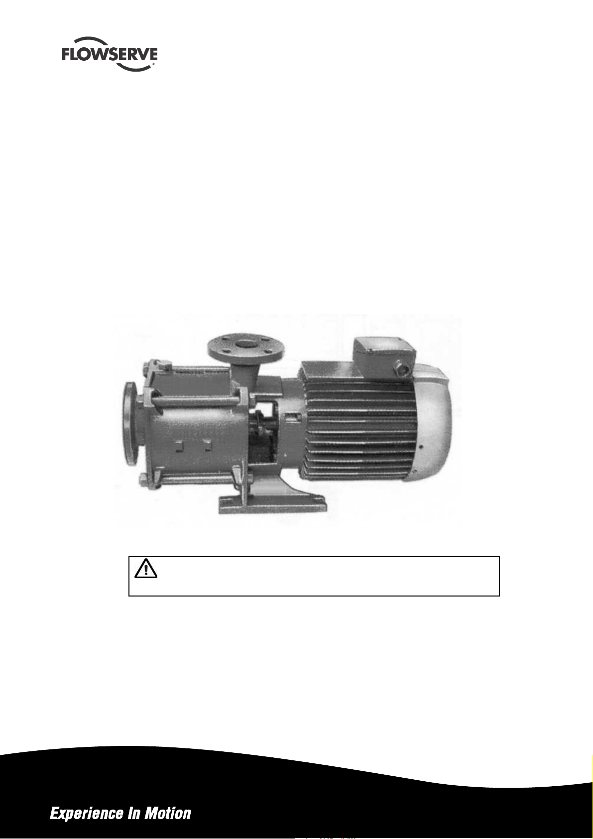
FM centrifugal pump
Multi-stage, centrifugal close-coupled pump with an axial
suction and a vertical axis discharge
PCN=71576526 – 03/07 (E)
Installation
Operation
Maintenance
These instructions must be read prior to installing,
operating, using and maintaining this equipment.
Page 2

CONTENTS
Page
1 INTRODUCTION AND SAFETY ......................... 4
FM USER INSTRUCTIONS ENGLISH 71576526 - 03/07
Page
6 MAINTENANCE................................................ 22
1.1 General.......................................................4
1.2 CE marking and approvals........................... 4
1.3 Disclaimer.................................................... 4
1.4 Copyright..................................................... 4
1.5 Duty conditions............................................ 4
1.6 Safety.......................................................... 5
1.7 Nameplate and safety labels........................ 8
1.8 Specific machine performance..................... 8
1.9 Noise level................................................... 9
2 TRANSPORT AND STORAGE......................... 10
2.1 Consignment receipt and unpacking.......... 10
2.2 Handling.................................................... 10
2.3 Lifting......................................................... 11
2.4 Storage...................................................... 11
2.5 Recycling and endof product life ............... 11
3 PUMP DESCRIPTION...................................... 11
3.1 Description and restrictions of use ............. 11
3.2 Nomenclature............................................ 12
3.3 Coverage charts........................................ 13
4 INSTALLATION................................................. 15
4.1 Location..................................................... 15
4.2 Foundation ................................................ 15
4.3 Piping........................................................ 15
4.4 Electrical connections................................ 17
4.5 Protection systems.................................... 18
6.1 General ..................................................... 22
6.2 Maintenance schedule............................... 23
6.3 Spare parts................................................ 25
6.4 Recommended spares............................... 25
6.5 Disassembly .............................................. 25
7 FAULTS; CAUSES AND REMEDIES................. 27
8 PARTS LIST AND DRAWINGS......................... 28
8.1 Sectional drawing ...................................... 28
8.2 Sectional drawing parts list........................ 29
8.3 General arrangement drawing.................... 29
9 CERTIFICATION .............................................. 29
10 OTHER RELEVANT DOCUMENTATION AND
MANUALS........................................................... 29
10.1 Supplementary User Instructions manuals29
10.2 Change notes .......................................... 29
10.3 Additional sources of information.............. 29
5 COMMISSIONING START-UP, OPERATION AND
SHUTDOWN ....................................................... 18
5.1 Direction of rotation.................................... 18
5.2 Guarding.................................................... 18
5.3 Priming and auxiliary supplies.................... 18
5.4 Starting the pump....................................... 19
5.5 Running the pump ..................................... 19
5.6 Stopping and shutdown ............................. 21
5.7 Hydraulic, mechanical andelectrical duty... 22
5.8 Pumps for Food Use or Potable Water....... 22
Page 2of 32 flowserve.com
Page 3

INDEX
FM USER INSTRUCTIONS ENGLISH 71576526 - 03/07
Page
Page
Additional sources (10.3) .....................................29
ATEX marking (1.6.4.2)..........................................7
CE marking and approvals (1.2).............................4
Certification (9)....................................................29
Change notes (10.2)............................................29
Cleaning prior to operation (5.8.1)........................22
Commissioning, start-up, operation (5).................18
Compliance, ATEX (1.6.4.1)...................................6
Configurations (3.1) .............................................11
Copyright (1.4).......................................................4
Coverage charts (3.3)..........................................13
Direction of rotation (5.1)......................................18
Disassembly (6.5)................................................25
Discharge piping(4.3.3) ......................................16
Disclaimer (1.3)......................................................4
Dismantling (see 6.5, Disassembly) .....................25
Drawings (8.1).....................................................28
Duty conditions (1.5)..............................................4
Electrical connections (4.4)..................................17
Electrical supply (4.4.2)........................................17
End of product life (2.5)........................................11
Faults; causes and remedies (7)..........................27
Final checks (4.3.4)..............................................17
First pump start up (5.4.2) ...................................19
Foundation (4.2) ..................................................15
Forces and moments (see 4.3.1)..........................16
General arrangement drawing (8.3)......................29
Gland packing (6.2.5)...........................................24
Guarding (5.2)......................................................18
Handling (2.2) ......................................................10
Hydraulic, mechanical andelectrical duty (5.7).....22
Inspection (6.2.2and 6.2.3)..................................24
Installation (4)......................................................15
Internal coating (6.2.6).........................................25
Lifting (2.3)...........................................................11
Location (4.1).......................................................15
Maintenance (6)...................................................22
Maintenance schedule (6.2).................................23
Mechanical seal (6.2.4)........................................24
Nomenclature (3.2) ..............................................12
Nameplate (1.7.1)..................................................8
Operating limits (see 3.1).....................................12
Orderingspare parts (6.3.1).................................25
Parts lists (8.2).....................................................29
Piping (4.3)..........................................................15
Protection systems (4.5) ......................................18
Pump masses (2.2.2)...........................................10
Receipt and unpacking (2.1) ................................10
Recommended spares (6.4).................................25
Recycling (2.5).....................................................11
Replacement parts (see 6.3 and 6.4)....................25
Running the pump (5.5) .......................................19
Safety action (1.6.3)...............................................5
Safety labels (1.7.2)...............................................8
Safety markings (1.6.1)..........................................5
Safety, protectionsystems (see 1.6 and4.8)
Sectional drawings (8.1) ......................................28
Sound level (see 1.9, Noise level)..........................9
Sources, additional information (10.3)..................29
Spare parts (6.3)..................................................25
Specific machine performance (1.8).......................8
Standard maintenance (6.2.1) .............................23
Starting the pump (5.4)........................................19
Stop/start frequency (5.5.6)..................................21
Stoppingand shutdown (5.6)...............................21
Storage, pump (2.4).............................................11
Storage, spare parts (6.3.2) .................................25
Suction piping (4.3.2)...........................................16
Supplementary manuals or information sources...29
Transport and storage (2) ...................................10
Trouble-shooting (see 7)...................................... 27
Vibration (5.5.5)...................................................21
Page 3 of 32 flowserve.com
Page 4
FM USER INSTRUCTIONS ENGLISH 71576526 - 03/07
1 INTRODUCTION AND SAFETY
1.1 General
These instructions must always be kept
close to the product's operating location or
directly with the product.
Flowserve products are designed, developed and
manufactured with state-of-the-art technologies in
modern facilities. The unit is produced with great
care and commitment to continuous quality control,
utilizing sophisticated quality techniques, and safety
requirements.
Flowserve is committed to continuous quality
improvement and being at service for any further
information about the product in its installation and
operation or about its support products, repair and
diagnostic services.
These instructions are intended to facilitate
familiarization with the product and its permitted use.
Operating the product in compliance with these
instructions is important to help ensure reliability in
service andavoid risks.The instructions may not
take into account local regulations; ensure such
regulations are observed by all, including those
installingthe product. Always coordinate repair
activity with operations personnel, and follow all
plant safety requirements and applicable safety and
health laws and regulations.
These instructions must be read prior to
installing, operating, using and maintaining the
equipment in any region worldwide. The
equipment must not be put into service until all
the conditions relating to safety noted in the
instructions, have been met.
1.2 CE marking and approvals
It is a legalrequirement that machinery and
equipment put into service within certain regions of
the worldshall conformwith the applicable CE
MarkingDirectives coveringMachinery and, where
applicable, Low Voltage Equipment, Electromagnetic
Compatibility (EMC), Pressure Equipment Directive
(PED) and Equipment for Potentially Explosive
Atmospheres (ATEX).
To confirm the Approvalsapplyingand if the product is
CE marked,checktheserial number plate markings
andthe Certification. (Seesection9, Certification.)
1.3 Disclaimer
Information in these UserInstructions is believed
to be reliable. In spiteof allthe efforts of Flowserve
Corporation to providesound and all necessary
information the content of thismanual mayappear
insufficient and is not guaranteed by Flowserve as
to its completenessor accuracy.
Flowserve manufactures products toexacting
International QualityManagement SystemStandards
as certifiedandaudited byexternalQuality Assurance
organizations. Genuine parts and accessories have
beendesigned,tested and incorporatedinto the
productsto help ensure theircontinued product quality
and performance in use. As Flowservecannot test
parts andaccessories sourced fromothervendors the
incorrect incorporationof such partsandaccessories
may adversely affect the performance andsafety
features of the products. The failureto properlyselect,
installor useauthorized Flowserve partsand
accessories isconsideredtobe misuse. Damageor
failurecausedby misuse is notcovered by the
Flowserve warranty. In addition,any modificationof
Flowserve products or removalof originalcomponents
may impairthesafety of these productsin theiruse.
1.4 Copyright
All rights reserved. No part of these instructions may
be reproduced, stored in a retrieval system or
transmitted in any form or by any means without
prior permission of Flowserve.
1.5 Duty conditions
This product has been selected to meet the
specifications of your purchaser order. The
acknowledgement of these conditions has been sent
separately to the Purchaser.A copy shouldbe kept
with these instructions.
The product must not be operated beyond
the parameters specified for the application. If
there is any doubt as to the suitability of the
product for the application intended, contact
Flowserve for advice, quoting the serial number.
Where applicable the Directivesandanyadditional
Approvalscover importantsafety aspects relating to
machinery andequipment and the satisfactory
provisionof technical documents andsafety
instructions. Where applicable this document
incorporatesinformationrelevant to these Directives
and Approvals.
Page 4 of 32 flowserve.com
If the conditions of service on your purchase order
are going to be changed (for example liquid pumped,
temperature or duty) it is requested that the user
seeks the written agreement of Flowserve before
start up.
Page 5
FM USER INSTRUCTIONS ENGLISH 71576526 - 03/07
1.6 Safety
1.6.1 Summary of safety markings
These UserInstructions containspecific safety
markings where non-observance of aninstruction
wouldcause hazards. The specificsafety markings
are:
This symbol indicates electrical safety
instructions where non-compliance will involve a
highrisk to personal safety or the loss of life.
This symbol indicates safety instructions where
non-compliance would affect personal safety and
could result in loss of life.
This symbol indicates “hazardous substances
and toxic fluid”safetyinstructions where non-
compliance wouldaffect personalsafety and could
result in loss of life.
This symbol indicates safety
instructions where non-compliance will involvesome
risk to safe operation andpersonalsafetyand would
damage theequipment or property.
This symbol indicates explosive atmosphere
zone marking according to ATEX. It is used in safety
instructions where non-compliance in the hazardous
area would cause the risk of an explosion.
1.6.3 Safety action
This is a summary of conditions and actions to
prevent injury to personnel and damage to the
environment and to equipment. For products
used in potentially explosive atmospheres
section 1.6.4 also applies.
NEVER DO MAINTENANCE WORK
WHEN THE UNIT IS CONNECTED TO POWER
GUARDS MUST NOT BE REMOVED WHILE
THE PUMP IS OPERATIONAL
DRAIN THE PUMPAND ISOLATE
PIPEWORK BEFORE DISMANTLING THE PUMP
The appropriate safety precautions should be taken
where the pumped liquids are hazardous.
FLUORO-ELASTOMERS (When fitted.)
When a pump has experienced temperatures over
250 ºC (482 ºF), partial decomposition of fluoro-
elastomers (example: Viton) will occur. In this
condition these are extremely dangerous and skin
contact must be avoided.
HANDLING COMPONENTS
Many precision parts havesharp corners and the
wearing of appropriate safety gloves and equipment
is required when handling these components. To lift
heavy pieces above 25 kg (55 lb) use a crane
appropriate for the mass andin accordance with
current local regulations.
This symbol is used in safety instructions to
remind not to rub non-metallic surfaces with a dry
cloth; ensure cloth is damp. It is used where non-
compliance in the hazardous area would cause the
risk of an explosion.
Thissignis nota safetysymbol butindicates
an importantinstruction intheassembly process.
1.6.2 Personnel qualification and training
All personnel involved in the operation, installation,
inspection and maintenance of the unit must be
qualified to carry out the work involved. If the
personnel in question do not already possess the
necessary knowledge and skill, appropriate training
and instruction must be provided. If required the
operator may commission the manufacturer/supplier
to provide applicable training.
Always coordinate repair activity with operations and
health and safety personnel, andfollow allplant
safety requirements and applicable safety and health
laws and regulations.
THERMAL SHOCK
Rapid changes in the temperature of the liquid within
the pumpcan cause thermal shock, which can result
in damage or breakage of components and should
be avoided.
NEVERAPPLY HEATTO REMOVE
IMPELLER
Trapped lubricantor vapor could cause anexplosion.
HOT (and cold) PARTS
If hot or freezing components or auxiliary heating
supplies can present adanger to operators and
persons enteringthe immediate area action must be
taken to avoid accidental contact. If complete
protection is not possible, the machine access must
be limited to maintenance staff only, with clear visual
warnings and indicators to those entering the
immediate area. Note: bearing housings must not be
insulated anddrive motors and bearings may be hot.
If the temperature is greater than 68 °C (175 °F)
or below 5 °C (20 °F) in a restricted zone, or
exceeds local regulations, action as above shall
be taken.
Page 5 of 32 flowserve.com
Page 6
HAZARDOUS LIQUIDS
Whenthepump is handlinghazardous liquids care
must be taken to avoidexposureto the liquid by
appropriatesittingof the pump, limiting personnel
access andbyoperatortraining. Ifthe liquidis
flammableand/or explosive, strictsafety procedures
must be applied.
Gland packingmust not be used when pumping
hazardous liquids.
PREVENTEXCESSIVE EXTERNAL
PIPE LOAD
Do not use pump as a support for piping. Do not
mount expansion joints, unless allowed by
Flowserve in writing, so that their force, due to
internal pressure, acts on the pumpflange.
FM USER INSTRUCTIONS ENGLISH 71576526 - 03/07
1.6.4 Productsused in potentially explosive
atmospheres
The following instructions for pumps andpump
units when installed in potentially explosive
atmospheres must be followedtohelpensure
explosion protection.
The terminology andprocedures ensure that the
installed pump is in compliance with the European
Directive 94/9/EC, knownas the ATEX Directive, which
is mandatory in Europe andmayalso bespecified in
other countries.Where applicable, bothelectricaland
non-electrical equipment must meet the requirements
94/9/EC.
Evenif theinstallationis in a region where ATEXis not
theapplicableregulation, the generalmeasures
described shall be followedto ensure safeoperation.
ENSURE CORRECTLUBRICATION
(See section 5, Commissioning, startup, operation
and shutdown.)
START THE PUMP WITHOUTLET
VALVE PARTOPENED
(Unless otherwise instructed at a specific point in the
User Instructions.)
This is recommended to minimize the risk of
overloading and damaging the pump motor at full or
zero flow. Pumps may be started with thevalve
further open only on installations wherethis situation
cannot occur. Pump outlet valve shallmay need to
be adjusted to comply with the duty followingthe
run-up process. (See section 5, Commissioning
start-up, operation and shutdown.)
NEVER RUN THE PUMP DRY
INLET VALVES TO BE FULLY OPEN
WHEN PUMP IS RUNNING
Runningthe pump at zero flow or below the
recommended minimumflow continuously will cause
damage to the seal.
DO NOT RUN THE PUMPAT
ABNORMALLY HIGH OR LOW FLOW RATES
Operating at a flow rate higher than normalor at a
flow rate with no backpressure on the pump may
overload the motor and cause cavitation. Low flow
rates may cause a reduction in pump/bearing life,
overheating of the pump, instability and
cavitation/vibration.
The measures are explained under the headings of:
Avoiding excessive surface temperature
Preventing build up of explosive mixtures
Preventing the generation of sparks
Preventing leakages
Maintaining the pump to avoid hazard
1.6.4.1 Scope of compliance
Use equipment only inthezone forwhichitis
appropriate. Always check that the driver, drive
couplingassembly, sealandpump equipmentare
suitably ratedand/or certified for theclassificationof
thespecific atmosphereinwhich theyareto be
installed.
WhereFlowserve has supplied only the bare shaft
pump, the Ex ratingapplies only to the pump. The
partyresponsiblefor assemblingthe pump set shall
selectthe coupling, driver andanyadditional
equipment, with the necessary CE Declaration of
Conformity establishing it is suitable for the area in
whichit is to be installed.
The output froma variable frequency drive (VFD)can
causeadditional heatingaffectsin the motor andso, for
pumps sets witha VFD,theATEX Certification forthe
motor muststatethat it iscovers the situationwhere
electricalsupply is fromthe VFD. This particular
requirementstill appliesevenifthe VFD isina safe
area.
Page 6 of 32 flowserve.com
Page 7
FM USER INSTRUCTIONS ENGLISH 71576526 - 03/07
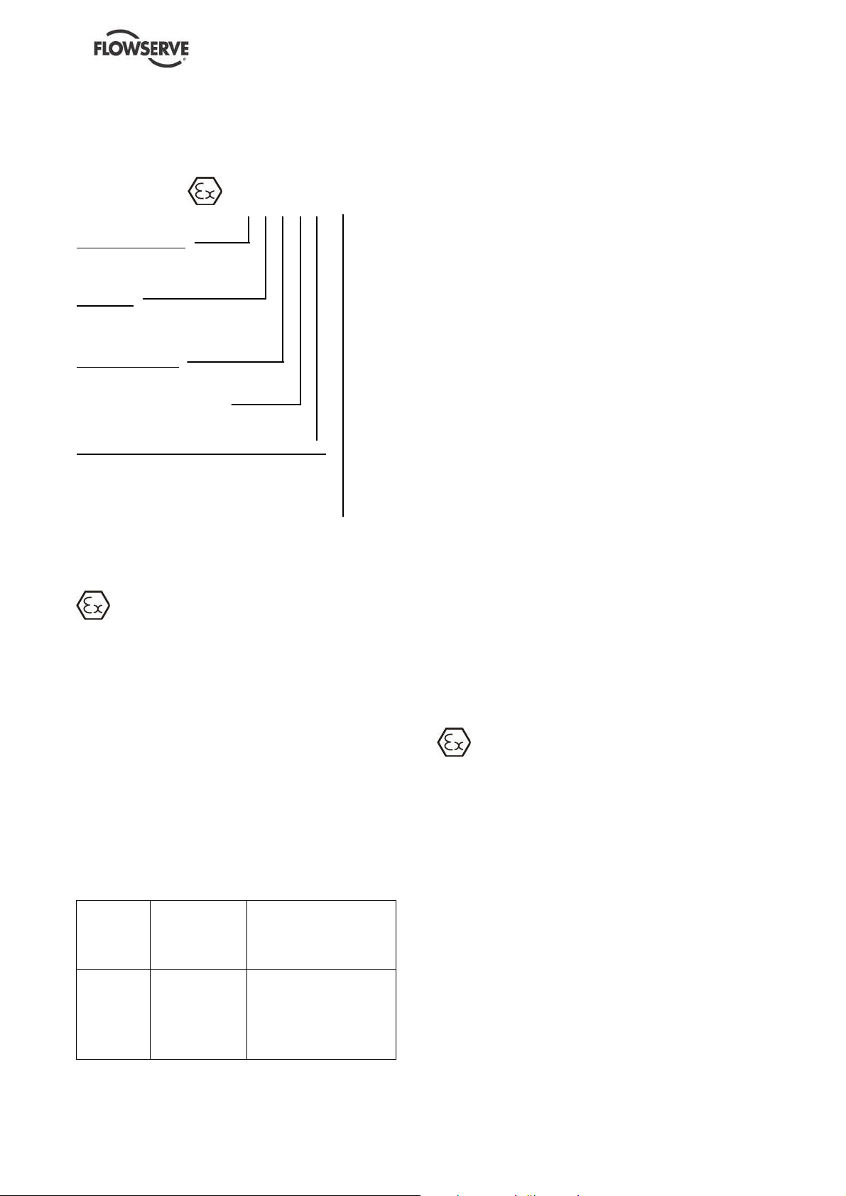
1.6.4.2 Marking
Anexample of ATEX equipment marking is shown
below. The actual classification of the pump will be
engraved on the nameplate.
II 2 GD c IIC 135 ºC (T4)
Equipment Group
I = Mining
II = Non-mining
Category
2 or M2 = High level protection
3 = normal levelof protection
Gas and/or Dust
G = Gas; D=Dust
c = Constructionalsafety
(in accordance with EN 13463-5)
Gas Group (Equipment Category 2 only)
IIA –Propane (typical)
IIB –Ethylene (typical)
IIC – Hydrogen(typical)
Maximumsurface temperature (TemperatureClass)
(seesection 1.6.4.3)
1.6.4.3 Avoiding excessive surface temperatures
ENSURE THE EQUIPMENT TEMPERATURE
CLASS IS SUITABLE FOR THE HAZARD ZONE
Pumps have a temperature class as stated in the
ATEX Ex rating on the nameplate. These are based
on a maximumambient of 40 °C (104 °F); refer to
Flowserve for higher ambient temperatures.
The responsibility for compliance with the
specified maximum liquid temperature is with the
plant operator.
Temperature classification “Tx” is used when the
liquid temperature varies andthe pump could be
installed in different hazardous atmospheres. In this
case the user is responsible for ensuringthat the
pump surface temperature does not exceed that
permitted in the particular hazardous atmosphere.
If an explosive atmosphere exists during the
installation, do not attempt to check the direction of
rotation by starting the pump unfilled. Even a short
run time may give a hightemperature resultingfrom
contact between rotating and stationary
components. Furthermore, confinement of liquid in
the pumpand pipes must be avoided (valveclosed).
If the liquid heats up this may cause excessive
pressure andlead to bursting of pumpcomponents.
Wherethereis anyrisk of the pumpbeing run against
a closed valve generatinghigh liquid and casing
externalsurface temperatures it is recommended that
users fit anexternal surface temperature protection
device.
Avoid mechanical, hydraulic or electrical overload by
using motor overload trips, temperature monitor or a
power monitor and make routine vibration monitoring
checks.
In dirty or dusty environments, regular checks must
be made and dirt removed from areas aroundclose
clearances, bearing housings and motors.
1.6.4.4 Preventing the build up of explosive
mixtures
The surface temperature on the pump is influenced
by the temperature of the liquid handled. The
ENSURE PUMP IS PROPERLY FILLED AND
VENTED AND DOES NOT RUN DRY.
maximum permissible liquid temperature depends
on the temperature class and must not exceed the
values in the table that follows.
Ensure pump and relevant suction anddischarge
pipeline system is totally filled with liquid at all times
during the pump operation, so that an explosive
The temperature rise at the seals, bearings and due
to the minimum permitted flow rate is taken into
account in the temperatures stated.
Temperature
classto
EN13463-1
T6
T5
T4
T3
T2
T1
Maximum
surface
temperature
permitted
85 °C (185°F)
100 °C (212°F)
135 °C (275°F)
200 °C (392°F)
300 °C (572°F)
450 °C (842°F)
Temperature limit of liquid
handled (* depending on
material and construction
variant- check which is
lower)
Consult Flowserve
Consult Flowserve
115°C (239 °F) *
180°C (356 °F) *
275°C (527 °F) *
400°C (752 °F) *
atmosphere is prevented. In addition it is essential to
make sure that seal chambers, auxiliary shaft seal
systems and any heating and cooling systems are
properly filled.
If the operation of the system cannot avoid this
condition the fittingof an appropriate dry run
protection device is recommended (eg liquid
detection or power monitor).
To avoid potential hazards fromfugitive emissions of
vapor or gas to atmosphere the surrounding area
must be well ventilated.
Page 7 of 32 flowserve.com
Page 8
FM USER INSTRUCTIONS ENGLISH 71576526 - 03/07
1.6.4.5 Preventing sparks
To prevent a potential hazard from mechanical
contact, the coupling guard must be non-sparking.
To avoid the potential hazard from random induced
current generating a spark the groundcontact on the
baseplate must be used.
Avoid electrostatic charge: do not rubnonmetallic surfaces with a dry cloth, ensurecloth is
damp.
Where applicable the coupling must be selected to
comply with 94/9/EC and correct alignment must be
maintained.
Additional requirements for metallic pumps on
non-metallic baseplates
When metallic components are fitted on a nonmetallic baseplate they must be individually earthed
(grounded).
1.6.4.6 Preventing leakage
The pump must only be used to handle liquids
for which it has been approved to have the correct
corrosion resistance.
Where there is a risk fromsuch tools or materials;
maintenance must be conducted in a safe area.
It is recommended that a maintenance planand
schedule is adopted. (See section 6, Maintenance.)
1.7 Nameplate and safety labels
1.7.1 Nameplate
For details of nameplate, see the Declaration of
Conformity, or separate documentation included with
these User Instructions.
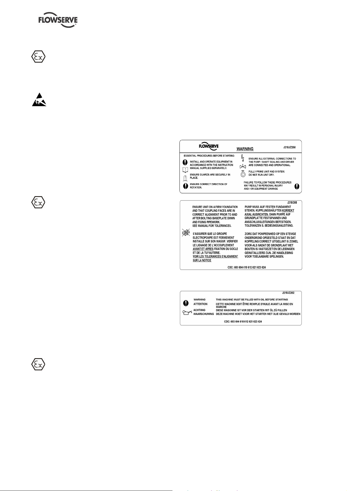
1.7.2 Safety labels
Avoidentrapmentof liquidin the pump andassociated
pipingdue to closingofsuction and dischargevalves,
which couldcause dangerous excessive pressures to
occurif there is heatinput to theliquid. Thiscanoccur
if the pump isstationaryor running.
Bursting of liquid containing parts due to freezing
must be avoided by draining or protectingthe pump
and ancillary systems.
Where there is the potential hazard of a loss of a
seal barrier fluid or external flush, the fluid must be
monitored.
If leakage of liquid to atmosphere can result in a
hazard, the installation of a liquid detection device is
recommended.
1.6.4.7 Maintenance to avoid the hazard
CORRECTMAINTENANCE IS REQUIRED
TO AVOID POTENTIAL HAZARDS WHICH GIVE A
RISK OF EXPLOSION
The responsibility forcompliance with
maintenance instructions is with the plant
operator.
Oil lubricated units only:
1.8 Specific machine performance
For performance parameters see section 1.5, Duty
conditions. When the contract requirement specifies
these to be incorporated into User Instructions these
are included here. Where performance data has
been supplied separately to the purchaser these
should be obtained and retained with these User
Instructions if required.
To avoid potential explosion hazards during
maintenance, the tools, cleaningand painting
materials used must not give rise to sparking or
adversely affect theambient conditions.
Page 8 of 32 flowserve.com
Page 9
FM USER INSTRUCTIONS ENGLISH 71576526 - 03/07
1.9 Noise level
Attention must be given to the exposure of personnel
to the noise, and local legislation will define when
guidance to personnel on noise limitation is required,
and when noise exposure reduction is mandatory.
This is typically 80 to 85 dBA.
The usual approach is to control the exposure time
to the noise or to enclose the machine to reduce
emitted sound.
You may have already specified a limiting noise level
when the equipment was ordered, however if no
noise requirements were defined, then attention is
drawn to the following table to give an indication of
equipment noise level so that you can take the
appropriate action in your plant.
Pump noise level is dependent on a number of
operational factors, flow rate, pipework design and
acoustic characteristics of the building, and so the
values given are subject to a 3 dBA tolerance and
cannot be guaranteed.
Similarly the motor noise assumed in the “pump and
motor” noise is that typically expected from standard
and high efficiency motors when on load directly
driving the pump. Note that a motor driven byan
inverter may show an increased noise at some
speeds.
If a pump unit only has been purchased for fitting
with your own driver then the “pump only” noise
levels in the table should be combined with the level
for the driver obtained from the supplier. Consult
Flowserve or a noise specialist if assistance is
required in combining the values.
It is recommended that where exposureapproaches
the prescribed limit, thensite noise measurements
should be made.
The values are in sound pressure level LpAat 1 m
(3.3 ft) fromthe machine, for “free field conditions
over a reflecting plane”.
For estimating sound power level LWA (re 1 pW)
then add 17 dBA to the soundpressure value.
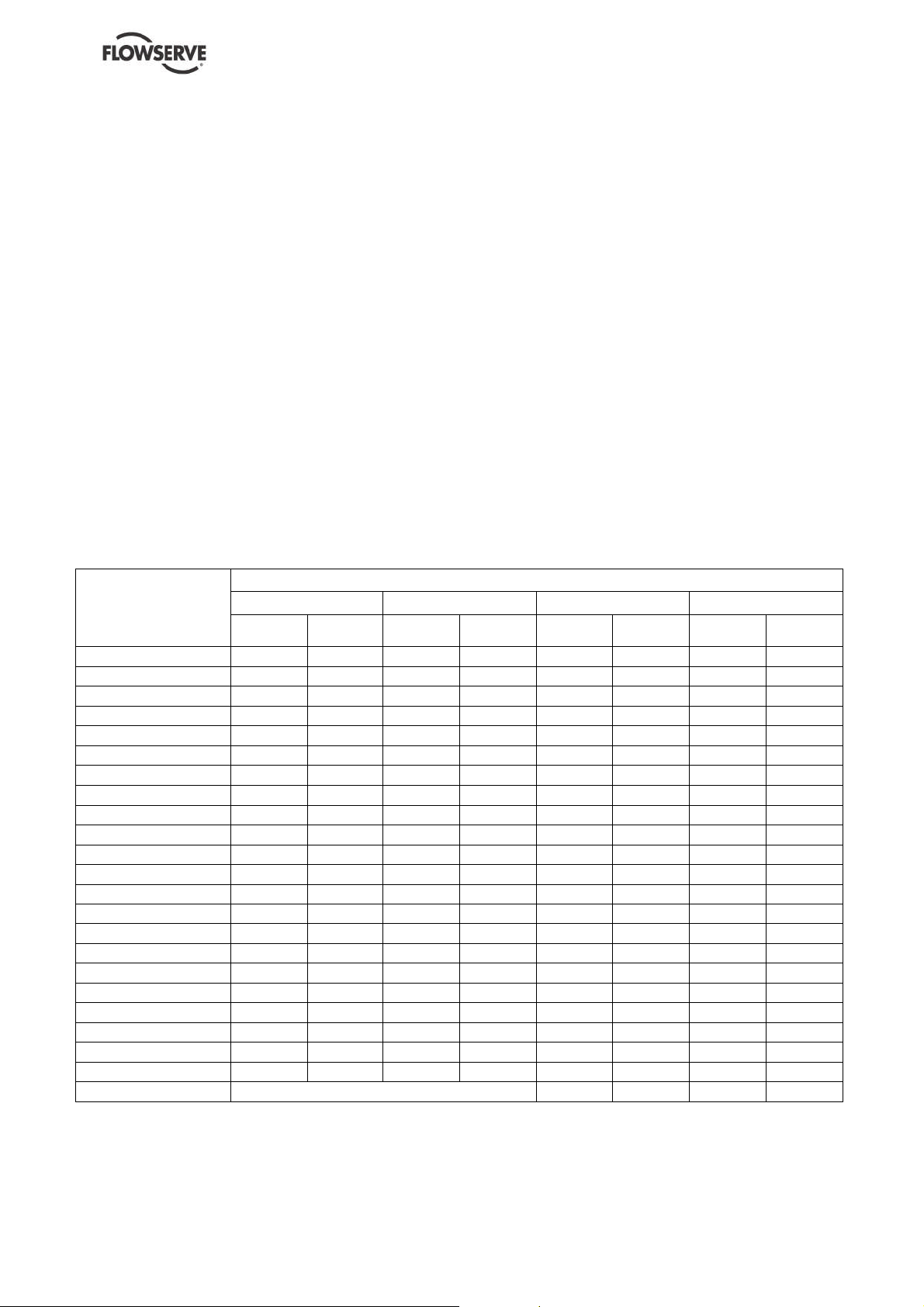
Motor size
and speed
kW (hp)
< 0.55(<0.75) 72 72 64 65 62 64 62 64
0.75(1) 72 72 64 66 62 64 62 64
1.1(1.5) 74 74 66 67 64 64 62 63
1.5(2) 74 74 66 71 64 64 62 63
2.2(3) 75 76 68 72 65 66 63 64
3 (4) 75 76 70 73 65 66 63 64
4 (5) 75 76 71 73 65 66 63 64
5.5 (7.5) 76 77 72 75 66 67 64 65
7.5 (10) 76 77 72 75 66 67 64 65
11 (15) 80 81 76 78 70 71 68 69
15 (20) 80 81 76 78 70 71 68 69
18.5 (25) 81 81 77 78 71 71 69 71
22 (30) 81 81 77 79 71 71 69 71
30 (40) 83 83 79 81 73 73 71 73
37 (50) 83 83 79 81 73 73 71 73
45 (60) 86 86 82 84 76 76 74 76
55 (75) 86 86 82 84 76 76 74 76
75 (100) 87 87 83 85 77 77 75 77
90 (120) 87 88 83 85 77 78 75 78
110 (150) 89 90 85 87 79 80 77 80
150 (200) 89 90 85 87 79 80 77 80
200 (270) 85 87 83 85
300 (400) 87 90 85 86
The noise level of machines in this range will most likely be of values which require noise exposure control, but typical values are
inappropriate.
Note: for 1 180 and 960 r/min reduce 1 450 r/minvalues by 2 dBA. For 880 and720 r/min reduce 1 450 r/min valuesby 3 dBA.
3 550 r/min 2 900 r/min 1 750 r/min 1 450 r/min
Pump
only
Typicalsound pressure level LpAat 1 mreference 20 μPa, dBA
Pump and
motor
Pump
only
Pump and
motor
Pump
only
Pump and
motor
Pump
only
Pump and
motor
Page 9 of 32 flowserve.com
Page 10
FM USER INSTRUCTIONS ENGLISH 71576526 - 03/07
In areas wherethe staff has to intervene, remember
that when the level of the soundpressure is:
below 70 dBA: it is not necessary to take special
precautions.
above 70 dBA: people working continuously in
the machine room must be supplied with
protective devices against noise.
below 85 dBA: no particular measures need to
be taken for casual visitors stayingin the room
during a limited period.
above 85 dBA: the room must be considered as
a dangerous area because of the noise and a
warning sign must be fixed at each entry
warning the people cominginto the room, even
for a short period, thatthey must wear hearing
protection.
above 105 dBA: special hearing protection
adapted to this noise level and to the spectral
noise components must be installedand a
warning signto this effect erected at each entry.
The staff in the roommust wear ear protection.
Make sure thatthe noise, which travels through the
walls andwindows, does not generate too high
noise levels in the machine room's surroundings.
To lift machines or pieces with one or several
suspension rings, only use hooks and chains in
compliance with the local regulations concerning
safety.
Never put cables, chains or ropes directly on or in
the suspension rings. Cables, chains or lifting ropes
must never present excessive bending.
Never bendthe lifting hooks, suspension rings,
chains, etc... which should only be made to endure
stresses within calculated limits. Remember that the
capacity of a lifting device decreases whenthe
direction of the lifting force direction makes an angle
with the device axis.
To increase the safety andthe efficiency of the lifting
device, allthe lifting elements must be as
perpendicular as possible. If necessary a lifting
beam can be placed between the winchand the
load.
When heavy pieces are lifted up, never stay or work
under the load or in the area which could be in the
path of the load if it were toswing or fall away.
2 TRANSPORT AND STORAGE
2.1 Consignment receipt and unpacking
Immediately after receipt of the equipment it must be
checked against the delivery and shipping
documents for its completeness and that there has
been no damage in transportation.
Any shortage and or damage must be reported
immediately to the Flowserve andreceived in writing
within one month of receipt of the equipment. Later
claims cannot be accepted.
Check any crates, boxes andwrappings for any
accessories or spare parts which may be packed
separately with the equipment or attached to side
walls of the box or equipment.
Each product has a unique serial number. Check
that this number corresponds with that advised and
always quote this number in correspondence as well
as when orderingspare parts or further accessories.
2.2 Handling
2.2.1 General instructions concerning handling
Boxes, crates, pallets or cartons may be unloaded
using fork lift vehicles or slings dependent on their
size andconstruction. See 2.3.1 for positioning of
slings.
To lift heavy pieces above 25 kg (55 lb), use a winch
adapted to the mass andin accordance with the
current local regulations.
Never leave a load hanging froma winch. The
acceleration or the slowing-down of liftingequipment
must stay in thesafety limits for the staff.
A winch must be positionedin such a way that the
load will be raised perpendicularly. Where possible
necessary precautions must be taken to avoid the
swing of the load, using for example two winches
making approximately the same angle, below 30°,
with the vertical.
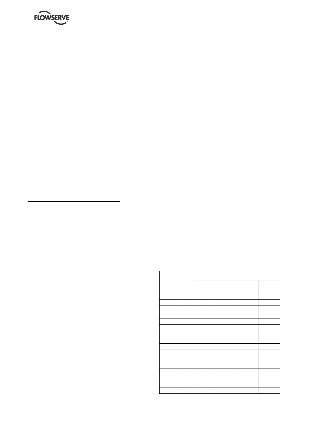
2.2.2 Pump masses
Unit Mass
Pump type
50 FM 2E 51 112 16 35
50 FM 3E 61 134 21 46
50 FM 2L 57 126 21 46
50 FM 3L 63 139 26 57
50 FM 4L 77 170 36 79
50 FM 5L 107 236 43 95
65 FM 2aE 77 170 36 79
65 FM 2cE 85 187 43 95
65FM 3bE 120 265 63 139
65 FM 3cE 120 265 63 139
65 FM 4cE 155 342 72 159
65 FM 1cL 60 132 26 57
65 FM 2aL 77 170 36 79
65 FM 2cL 85 187 43 95
65 FM 3bL 120 265 63 139
65 FM 3cL 120 265 63 139
65 FM 4cL 155 342 72 159
FM
kg lb kg lb
Motor Mass
Page 10 of 32 flowserve.com
Page 11

FM USER INSTRUCTIONS ENGLISH 71576526 - 03/07
All motors (for masses see the motor
description plate) must be handled with a winch.
For masses above 25 kg (55 lb), manual
handling is forbidden.
2.3 Lifting
2.3.1 Slinging of motorpumps units
Use handling means in accordance with motor
pump unit mass mentioned on the CE plate. For the
masses of the pumps bare end of shaft see table §
2.2.2 and nameplate.
To avoid distortion, lift up motor
pump unit as shown:
Motor pump unit
2.5 Recycling and end of product life
At theend of the service life of the product or its parts,
the relevant materials and partsshould be recycledor
disposed of usingan environmentally acceptable
method andlocal regulations.
If the product contains substances whichare harmful
to theenvironment, these shouldbe removedand
disposed of in accordance with currentregulations.
This also includes the liquids and or gases in the
"sealsystem"or other utilities.
Makesure that hazardous substances or toxic
fluids are disposed ofsafely and that the correct
personal protective equipment is used. The safety
specifications must be in accordance with the current
regulations at all times.
3 PUMP DESCRIPTION
3.1 Description and restrictions of use
The multi-stage centrifugal pump is designed for the
pumping of cold water or all clear liquids which are
not solid andliquid mixtures, non-corrosive, nonabrasive or non-explosive when in contact withthe
pump motor unit and its working parts (Important: for
other liquids consult Flowserve for beforehand
advice).
When handling always wear gloves, safety
boots andan industrial safety helmet.
For masses above 25 kg (55 lb), manual
handling is forbidden.
2.4 Storage
Store the pumpin a clean, dry
location away from vibration. Leave piping
connection covers in place to keep dirt and other
foreign material out of pump casing. Turn pump at
intervals to prevent brinelling of the bearings and the
seal faces, if fitted, from sticking.
Do not store pumps starting on the fan guard.
The pump may be stored as above for upto 6
months. Consult Flowserve for preservative actions
when a longer storage period is needed.
The FM type is acentrifugal, multi-stage, closecoupled pump with an axial inlet and a vertical axis
outlet.
The pump must be stored in anon explosive,
ventilated location, sheltered frombad weather, dust
and vibrations.
The reliability of the delivered machine can only be
ensured if it is used accordingto the conditions
given in this manual. The maximum values specified
in this manual must never be exceeded.
Page 11 of 32 flowserve.com
Page 12

FM USER INSTRUCTIONS ENGLISH 71576526 - 03/07
Maximumworking pressure at discharge
.................................................25 bar (363 psi)
Maximumworking pressure at suction
.................................................16 bar (232 psi)
Maximum pumped fluid temperature
(1)
105 °C (221 °F): Impeller and diffuser Castiron
or Bronze
Minimum pumped fluid temperature
.................................................-10 °C (14 °F)
Maximumambient temperature
.................................................40 °C (104 °F)
Maximumsolid suspension
....................................50 g/m3(0.003 lbm/ft
Density...............................1
Viscosity............................. 1 mm2/s (31 SSU)
Frequency.............................................50 Hz
Maximumrotation speed ....................... 2850
(1)
-1
min
If mechanical seal: maximum temperature 80 °C
(176 °F)
The maximum speed is shown on the
pump nameplate.
3.2 Nomenclature
Characteristics shown on the nameplate fixed on the pump are as shownbelow:
Each pump is supplied with the following nameplate:
3
)
Speed of rotation
Pump type
Flowrate
Head
Radial/thrust bearing
Year of construction +
Manufacture number
Each pump unit is supplied with the following nameplate:
Mass of the set
Mass
Maximum admissible
Pressure at 20 °C (68 °F)
Maximum / minimum
temperature
Page 12 of 32 flowserve.com
Page 13

3.3 Coverage charts
3.3.1 2850 min-1(50 Hz): Operating ranges (Q, H)
FM USER INSTRUCTIONS ENGLISH 71576526 - 03/07
Page 13 of 32 flowserve.com
Page 14

FM USER INSTRUCTIONS ENGLISH 71576526 - 03/07
Page 14 of 32 flowserve.com
Page 15

FM USER INSTRUCTIONS ENGLISH 71576526 - 03/07
4 INSTALLATION
Equipment operated in hazardous locations
must comply with the relevant explosion protection
regulations. See section 1.6.4, Products used in
potentially explosive atmospheres.
All equipment must be grounded.
4.1 Location
The pump shouldbe located to allow room for
access, ventilation, maintenance and inspection with
ample headroom for lifting and should be as close
as practicable to the supply of liquid to be pumped.
a) Levellingon the suction flange with a frame level
or on the discharge flange with a levelling
instrument.
b) Admissible defect 0.5 mmfor 1 meter (0.02 in
for 3.3 ft).
c) Wedge under the pump.
Level
Frame
level
4.3 Piping
The user must verify that the equipment is
isolated from any external sources of vibration.
Protective covers are fitted to the
pipe connections to preventforeign bodies entering
during transportation and installation. Ensure that
these covers are removed fromthe pumpbefore
connecting any pipes.
4.2 Foundation
There are many methods of installing
pump units to their foundations. The correct method
depends on the size of the pump unit, its location
and noise vibration limitations. Non-compliance with
the provision of correct foundation and installation
may lead to failure of the pumpand as such would
be outside the terms of the warranty.
Anchor bolts must be appropriate for the foot bolt
holes. Use anchor bolts of accepted standards and
sufficient length so that they may be clamped safely
in the grout.
NFE 27 811
Provide sufficient space in the foundation to
accommodate the anchor bolts. If necessary, provide
concrete gullets.
4.3.1 Suction and discharge piping
The dimensions of the pipes do not directly depend
on suction and discharge diameters of the pump:
a) First, choose a flow speed <2 m/s (7 ft/s) at
suction, andabout 3 m/s (10 ft/s) at discharge.
b) Take into account the available NPSH, which
must be superior to the required NPSH of the
pump.
Never use pump as a support for
piping.
Do not mount expansion joints in
such a way that their force, due to internal pressure,
may act on the pump flange.
Maximumforces and moments allowed on the pump
flanges vary with the pump size and type. These
external strains may cause misalignment, heating of
the bearings, vibrations andthe possible failure of
the pumpcasing.
When designing the pipework (§ 5.3.1, § 5.3.2, §
5.3.3) take necessary precautions in order not to
exceed maximum allowed strains.
Forces and moments applied to the pumpflanges
must never exceed the values shown in the following
table:
Page 15 of 32 flowserve.com
Page 16

FM USER INSTRUCTIONS ENGLISH 71576526 - 03/07
Forces
F
Z
40
(90)
50
(112)
40
(90)
50
(112)
daN (lbf)
F
35
(79)
45
(101)
50
(112)
68
(153)
Vertical pipework
perpendicular to
the shaft
Axial pipework
parallel to the
axis
DN
40
(1"1/2)
50
(2")
50
(2")
65
(2"1/2)
F
Y
30
(67)
40
(90)
45
(101)
58
(130)
Forces and moments values are applied to the
whole flanges and not flange by flange.
Ensure piping and fittings are flushed
before use.
Ensure piping for hazardous liquids is
arranged to allow pump flushing before removal of
the pump
4.3.2 Suction piping
Moments
m.daN (lbf.ft)
X F
60
(135)
80
(180)
80
(180)
102
(229)
M
23
(170)
27
(199)
27
(199)
30
(221)
Y
M
27
(199)
30
(221)
30
(221)
33
(243)
Z
M
X M
34
(251)
37
(273)
37
(273)
40
(295)
e) If an inlet valve is necessary, choose a model
with direct crossing.
Do not tighten flanges before the final
check (see § 4.3.4).
4.3.2.2 Design of a suction lift line
The inlet pipe must be as short and as direct as
possible, never place an elbow directly on the pump
inlet nozzle.
FM
Sufficient
immersion: I
49
(361)
54
(398)
54
(398)
60
(443)
Valve
Non-return valve
Motor
4.3.2.1 Design of a flooded suction line
The suction line must be as short and direct as
possible, never mount an elbow directly on the inlet
flange of the pump.
Valve
FM
Non-return valve
Motor
Flooded suction pump
a) Avoid sharp elbows or sudden narrowing. Use
convergent 20° (total angle).
b) Arrange the piping so that there are no air
pockets (no bulges).
c) If high points cannot be avoided in suction line,
provide themwith air relief cocks.
d) If a strainer is necessary, its net area should be
three or four times the area of the suction pipe.
I 3 x D
Sump suction configuration
a) Avoid sharp elbows or sudden narrowing. Use
convergent 20° (total angle) with upright
generating.
b) Arrange that the suction piping is inclined
upwards towards the pump ensuring that there
are no peaks.
c) If a foot valve is necessary, do not oversize it
because it would generate pulsations (valve
beating).
Do not tighten flanges before the final
check (see § 4.3.4).
4.3.3 Discharge piping
4.3.3.1 Design of a discharge line
a) If discharge line is provided with a divergent, its
total angle will be between 7° and 12°.
b) Install the discharge valve after the non-return
valve downstream.
Page 16 of 32 flowserve.com
Page 17

The non-return valve will be set in the discharge
pipe to protect the pump fromany excessive
pressure surge and from reverse rotation.
If necessary, a control manometer (pressure gauge)
can be connected on the piping.
Control manometer
Setting of the control manometer
Do not tighten flanges before the final
check (see § 4.3.4).
Never connect the electric motor
before the setting has been completely finished.
4.3.4 Final checks
a) Check the tightening of anchor bolts. Tighten
themif necessary.
b) Check that protective covers on suction and
discharge flanges are removed.
c) Check that holes of piping flanges are parallel
and correspondto those of the pump.
d) Tighten suction anddischarge flanges.
e) If it is planned, connect piping(hydraulic,
pneumatic, sealing system).
f) Control seal and the working of auxiliary piping.
4.4 Electrical connections
4.4.1 Safety conditions about electrical
connections
Electric connections must be carried
out by a qualified electrician, following the local rules
and regulations in force.
It is important to beaware of the EUROPEAN
DIRECTIVE on potentially explosive areas where
compliance with IEC60079-14is an additional
requirement for making electrical connections.
Avoid mechanical, hydraulic or electrical
overload by using motor overload trips or a power
monitor and make routine vibration monitoring.
FM USER INSTRUCTIONS ENGLISH 71576526 - 03/07
Itisimportant to be aware oftheEUROPEAN
DIRECTIVEon electromagnetic compatibility when
wiringupandinstallingequipment onsite.Attention
must be paidtoensurethat the techniques usedduring
wiring/installation do notincrease electromagnetic
emissionsor decreasetheelectromagneticimmunity of
theequipment,wiringoranyconnecteddevices. Ifin
doubt, contactFlowserve foradvice.
Before connecting the electric powersupply, if the
device has been kept in a damp atmosphere, have
the insulation resistance of the electric motor
checked.
This resistance should have a value of not less than
5 000 ohms for each volt of the supply.
Carry out the groundconnections according to the
current local regulations.
The motor must be protected. The protection must
therefore be ensuredby a magneto thermalbreaker
located between the section switch and the motor.
This breaker can beconnected to fuses.
Use a breaker sized and provisionally adjusted to
the current specified on the descriptionplate.
It is recommended to provide the power supply of
the electric motor with a monitoring device allowing
the machine to be shut down safely.
A device to provide emergency stopping shall be
fitted.
4.4.2 Electrical supply
Make sure thatthe voltage of the electricalsupply
line is correct for that specified on the motor
description plate.
Make sure thatthe supply wires have sufficient load
capacity for the correct running of the installation.
4.4.3 Wiring Instructions
The motors are closedtypeIP55 class E - 50 Hz
230/ 400 V upto3.7 kW - 50 H:
The motors canbe directly supplied with 230 or
400 V accordingtothe coupling(starting with
230 V is possible but notadvised)
400 V from5.5 kW-50 Hz:
The motors canbe directly supplied with 400 V
(starting with400 V is possiblebutnot
advised). Astatoric start is advised.
Page 17 of 32 flowserve.com
Page 18

FM USER INSTRUCTIONS ENGLISH 71576526 - 03/07
Connectionwiring diagramfor three phase motors:
Delta connection
Wire up the motor terminals according to the voltage
supply, in accordance with the description plate fixed
on the motor and with the connection wiring diagram
mentionedon the terminal box as opposite.
To avoid any risk of jamming, the
direction of rotation will be checked after priming of
the pump(§ 5.3.1, 5.3.2) and before the first start (§
5.4.2).
Star connection
4.5 Protection systems
The following protection systems are
recommended particularly if the pump is installed in
a potentially explosive area or is handling a
hazardous liquid. If in doubt consult Flowserve. If
there is any possibility of the systemallowing the
pump to run against a closed valve or below
minimumcontinuous safe flow aprotection device
should be installed to ensure the temperature of the
liquid does not rise to an unsafe level.
5 COMMISSIONING START-UP, OPERATION AND SHUTDOWN
These operations must only be carried out
by qualified personnel.
5.1 Direction of rotation
Starting or operating pumps with the
wrong direction of rotation can be harmful to the
pumps. Ensure that the pump rotation is the same
as the arrow on the pump casing.
It is preferable to check the direction of rotation
before installing the coupling. If not, the pump must
be filled in with the liquid before start-up.
If maintenance work has been carried
out to the site's electricity supply, the direction of
rotation should be re-checked as above in case the
supply phasing has been altered.
5.2 Guarding
Guarding is supplied fitted to the pump set.
If this has been removed or disturbedensure that all
the protective guards around the pump coupling and
exposed parts of theshaft are securely fixed.
5.3 Priming and auxiliary supplies
If there are anycircumstances in which thesystem
can allow the pump to run dry, or start up empty, a
power monitor should be fitted to stop the pump or
prevent it from being started. This is particularly
relevant if the pump is handling a flammable liquid.
If leakage of product from the pump or its associated
sealing systemcan cause a hazard it is
recommended that an appropriate leakage detection
system is installed.
To prevent excessive surface temperatures at
bearings it is recommended that temperature or
vibration monitoring are carried out. See sections
5.5.4 and 5.5.5.
If a defect of cooling can lead to temperature higher
than those acceptable a system of cooling
surveillance must be installed.
Except whenexplicitly required by the customer in
the specifications, when a possibility of reverse
rotation exists the customer must install a reverse
rotation protection device.
The customer must install all equipment required to
avoid water hammer.
Where there is any risk of the pumpbeing run
against a closed valve generatinghigh liquid and
casing externalsurface temperatures it is
recommended that users fit an external surface
temperature protection device.
Ensure allelectrical, hydraulic,
pneumatic, sealant and lubricationsystems (as
applicable) are connected and operational.
Ensure the inlet pipe andpump
casing are completely fullof liquid before starting
continuous duty operation.
These operations must be carried out by personnel
with approved qualifications.
5.3.1 Priming of a flooded pump
a) Close the discharge valve, fill the pump by
openingthe suction valve. Let air escape by
removing the plug located on the piping.
b) The discharge pipe is headed and there is a by-
pass valve on the check valve, open slightly the
discharge valve and the by-pass of the check
valve.
c) When the pump is totally free of air bubbles,
replace the plugs.
Page 18 of 32 flowserve.com
Page 19

Air escape
Air escape
Priming of a flooded pump
5.3.2 Priming of a sumpsuction pump
* With footvalve:
a) Fill suction pipe and casing with liquid froman
independent source (pressure 1 to 2 bars or 15
to 30 psi).
b) Let air escape by removing the plugs located on
the piping.
c) When the pump is totally free of air bubbles,
replace the plugs.
External source
FM USER INSTRUCTIONS ENGLISH 71576526 - 03/07
5.4 Starting the pump
5.4.1 Bring controls and preparation before the
first starting and after each service call
Necessarily:
a) Check the tightening of the different plugs.
b) Check that the gland lightly tightens the packing
rings.
c) Risk of seal ringoverheating.
d) Check the direction of rotation of the motor.
Refer to the rotation arrowof the pump.
e) DO NOT FORGET TO REMOUNT THE
SHIELD GRID ON THE MOTOR STOOL
f) Open all inlet valves (if existing).
g) Close the outlet valve and the bypass valve.
h) Ensure inlet pipe and pump casing are
completely full of liquid.
5.4.2 First pumpstart-up
Suction valves must be fully open
when pump is running. Never run the pump dry, it
will cause damage.
a) Start motor and check outlet pressure.
b) If pressure is satisfactory, slowly OPENthe
outlet valve.
c) Do not run the pump with the outlet valve closed
for a period longer than 30 seconds.
d) If NO pressure, or LOW pressure, STOP the
pump. Refer to fault finding chart for fault
diagnosis.
Priming of a sump suction configuration
with foot valve
* Without foot valve:
Priming may be accomplished by means of venting
system.
Foot valves are not recommended when
the pumped liquid has suspendedsolid particles.
They may lodge between foot valve seat and
shutter.
The pump should run smoothly andwithout
vibration.
The pump must never run at a capacity less than
10 % of the best efficiency point.
Never remove a plug when the pump is
running.
5.5 Running the pump
5.5.1 Venting the pump
Vent the pump to enable all trapped air to
escape takingdue care with hot or hazardous
liquids.
Under normal operating conditions, after the pump
has been fully primedand vented, it should be
unnecessary to re-vent the pump.
Page 19 of 32 flowserve.com
Page 20

FM USER INSTRUCTIONS ENGLISH 71576526 - 03/07
424
0
5.5.2 Pump fitted with a stuffing box
If the pump has a packed gland there must be some
leakage fromthe gland. Gland nuts should initially
be finger-tight only. Leakage should take place soon
after the stuffing box is pressurized. If no leakage
takes place the packing willbegin to overheat. If
overheating takes place the pump should be
stopped andallowed to cool before being re-started.
When the pump is re-started it should be checked to
ensure leakage is taking place at the packed gland.
When adjusting an operating stuffing box
(shield grids removed for this operation), the
operator must be very careful. Safety gloves are
compulsory and loose clothes are not allowed
(above all to the arms) to avoid being caught by the
pump shaft.
The pump should be run for ten minutes with steady
leakage andthe gland nuts tightened by 10 degrees
at a time until leakage is reduced to an acceptable
level.
The temperature of the glandshould be checked
after each roundof tightening. If the temperature
starts to climbrapidly then back off the gland nuts
until the temperature drops down. Wait for the
temperature to stabilize before tightening again.
The leakage must not be reduced below a rate of 20
drops per minute. Bedding in of the packing may
take several hours.
421342002445
4610
With a mechanicalseal, the
maximum temperature is limited to 80 °C (176 °F)
whatever the internalconstruction of the pumpis
(Cast iron or Bronze).
NEVER RUN A MECHANICAL SEAL
DRY, EVEN FOR A SHORT WHILE.
SAFETY INSTRUCTIONS WHEN THE PUMP IS
RUNNING:
If hot or freezingcomponents of the machine
can present a danger to operators, they must be
shielded to avoid accidental contact. If a 100 %
protection is not possible, the machine access must
be confined to the maintenance staff only.
Shield grids being removed during installation
of the gland packing, it must be ensured that they
are replaced as soon as this operation is completed.
5.5.3 Pump fitted with a mechanical seal
A mechanical seal ensures a seal without leakage
and does not need any adjustment. Nevertheless if a
light leakage occurs during start-up, it should
disappear after theinitial running in of the friction
faces.
If the temperature is greater than 80 °C (176
°F), a warningplate must be clearly placed on the
pump.
It is strictly forbidden to open switch
cupboards, switch boxes, or all other live electric
equipment. If it is necessary to open them in order to
take readings, to carry out tests or adjustments for
example, only a skilled technician may do themwith
adapted tools. Make sure that physical protections
against electrical risks are used.
5.5.4 Bearings
If the pumps are working in a potentially
explosive atmosphere, temperature or vibration
monitoring at the bearings is recommended. If
bearing temperatures are to be monitored it is
essential that a benchmark temperature is recorded
at the commissioning stage and after the bearing
temperature has stabilized.
Record the bearing temperature (t) and the
ambient temperature (ta)
Estimate the likely maximum ambient
temperature (tb)
Page 20 of 32 flowserve.com
Page 21

FM USER INSTRUCTIONS ENGLISH 71576526 - 03/07
Set the alarmat (t+tb-ta+5) C [(t+tb-ta+10) F]
and the trip at 100 C (212F) for oil lubrication
and 105 C (220 F) for grease lubrication
It is important, particularly with grease lubrication, to
keep a check on bearing temperatures. After start up
the temperature rise should be gradual, reaching a
maximum after approximately 1.5 to 2 hours. This
temperature rise shouldthen remain constant or
marginally reduce with time.
5.5.5 Normalvibration levels, alarm and trip
For guidance, pumps generally fall under a
classification for rigid support machines within the
International rotatingmachinery standards and the
recommended maximum levels below are based on
those standards.
Alarm and trip values for installed
pumps should be based on the actual
measurements (N) taken on site on the bearing
housings of the pump in the fully commissioned as
new condition.
The example (N) value is given for the preferred
operating flow region (typically this may extend to 70
to 120 % of the pump best efficiency point);outside
the preferred flow region the actual vibration
experienced may be multiplied by up to 2.
These standard values can vary with the rotational
speed and the power absorbed by the pump. For
any special case, do not hesitate to consult us.
Measuring vibration at regular intervals will then
show any deterioration in pump or systemoperating
conditions.
Vibration Velocity-
unfiltered
Normal N 5.6 (0.22)
Alarm N x1.25 7.1 (0.28)
Shutdown Trip N x 2.0 11.2 (0.44)
Horizontal Configuration
mm/s (in./s) r.m.s.
5.5.6 Stop/start frequency
Pumpsets are normally suitable for the number of
equally spaced stop/starts perhourshown in the table
below. Check actualcapability of the driverand
control/startingsystembeforecommissioning.
Motor rating kW (hp)
Up to 15 (20) 15
Between 15 (20) and 90 (120) 10
90 (120) to 150 (200) 6
Above 150 (200) Refer
Maximum start ups per
hour
Where duty andstandby pumps areinstalled it is
recommended that they are runalternately every
week.
5.6 Stopping and shutdown
According to hydraulic conditions of
the installation andits automation degree, stop and
restart procedures can have different forms.
Nevertheless allof them must respect imperatively
the following rules:
5.6.1 Stopping < 1 hour
a) Isolate motor.
b) Avoid reverse rotation of the pump.
c) Make sure that the discharge line pressure does
not reach the foot valve.
5.6.2 Stopping < 1 month
a) Isolate motor.
b) Avoid reverse rotation of the pump.
c) Make sure that the discharge line pressure does
not reach the foot valve.
d) Close the outlet valve. Eventually close the inlet
valve.
e) Switch off external power supply,
flushing/quench, cooling liquid.
5.6.3 Shutdown > 1 month
a) Isolate motor.
b) Avoid reverse rotation of the pump.
c) Make sure that the discharge line pressure does
not reach the foot valve.
d) Close the outlet valve. Eventually close the inlet
valve.
e) Switch off external power supply,
flushing/quench, cooling liquid.
f) Keep the pump fully filled with water. Incase of
pumped liquid other than water, drain the pump
entirely.
g) Turn once per week the pump shaft of one or
two turns.
h) Never restart the pump without carrying out the
verifications recommended before starting (see
§ 5.4.1).
When ambient temperatures are
likely to dropbelow freezing point, the pump and any
cooling andflushing arrangements must be drained
or otherwise protected.
5.6.4 Restarting in continuous running
a) Ensure that the pumpis completely fullof liquid.
b) Ensure a continuous supply with a sufficient
available NPSH.
c) Ensure a backpressure so that the motor power
is not in excess.
d) Respect the startingfrequency
imposed by the motor manufacturer.
e) Protect the pump against water hammer
when stopping or starting.
Page 21 of 32 flowserve.com
Page 22

FM USER INSTRUCTIONS ENGLISH 71576526 - 03/07
5.7 Hydraulic, mechanical and electrical duty
This product has been supplied to meet the
performance specifications of your purchase order,
however it is understood that duringthe life of the
product these may change. The followingnotes may
helpthe user decide how to evaluate the
implications of any change. If in doubt contact your
nearest Flowserve office.
5.7.1 Specific gravity (SG)
Pumpcapacity andtotal head in meters (feet) do not
change with SG, however pressure displayed on a
pressure gauge is directly proportional to SG. Power
absorbed is also directly proportional to SG. It is
therefore important to check that any change in SG
will not overload the pump driver or over-pressurize
the pump.
5.7.2 Viscosity
For a given flow rate the total head reduces with
increased viscosityand increases with reduced
viscosity.Also for a given flow rate the power
absorbed increases with increased viscosity, and
reduces with reduced viscosity. It is important that
checks are made with your nearest Flowserve office
if changes in viscosity are planned.
5.7.3 Pump speed
Changing pump speed effects flow,total head,
power absorbed, NPSHR, noise and vibration. Flow
varies in direct proportion to pumpspeed, head
varies as speed ratio squared and power varies as
speed ratio cubed. The new duty, however, will also
be dependent on the systemcurve. If increasing the
speed, it is important therefore to ensurethe
maximum pump working pressure is not exceeded,
the driver is not overloaded, NPSHA> NPSHR, and
that noise andvibration are within local requirements
and regulations.
5.7.4 Net positive suction head (NPSHA)
NPSH available (NPSHA) is the head available at the
impeller inlet, above thevapor pressure of the
pumped liquid.
NPSHrequired (NPSHR)is the minimumheadrequired
at theimpeller inlet,above thevaporpressure ofthe
pumped liquid,toavoidexcessivecavitationand
extreme performance degradation.
Itis important that NPSHA> NPSHR. The margin
between NPSHA> NPSHRshould beas large as
possible.
If in doubt please consult your nearest Flowserve
office for advice and details of the minimum
allowable margin for your application.
5.7.5 Pumped flow
Flow must not fall outside the minimum and
maximum continuous safe flow shown on the pump
performance curve and or data sheet.
5.8 Pumps for Food Use or Potable Water
Ifthe pump has not been specifically orderedfora food
or drinking water applicationit must not beusedfor
these types ofapplications. If it has beenordered for
thistype ofapplicationthe following recommendations
are to be followed.
5.8.1 Cleaning prior to operation
Pumps that areto be usedforafoodor drinkingwater
applicationshould becleaned before being putinto
initial operation andaftertheinstallationof spare parts
thatare incontactwiththe liquid.
Cleaningonce the pump has beencommissionedwill
dependontheapplicationandoperatingconditions.
The user must ensure that thecleaning procedures are
suitable fortheapplicationandoperatingconditions,
and local regulations.
6 MAINTENANCE
6.1 General
If a belt drive is used, the assembly and
tension of the belts must be verified during regular
maintenance procedure.
In dirty or dusty environments, regular checks
must be made and dirt removed from areas around
close clearances, bearing housings and motors.
It is the plant operator's responsibility to
ensure that allmaintenance, inspection and
assembly work is carried out byauthorized and
qualified personnel who have adequately
familiarized themselves with thesubject matter by
studying this manual in detail (see also section
1.6.2).
Any work on the machine must be performedwhen it
is at a standstill. It is imperative that theprocedure
for shutting down the machine is followed, as
described in section 5.6.
If any change in NPSHAis proposed, ensure these
margins are not significantly eroded. Refer to the
pump performance curve to determine exact
requirements particularly if flow has changed.
Page 22 of 32 flowserve.com
On completion of work all guards and safety devices
must be re-installed and made operative again.
Page 23

FM USER INSTRUCTIONS ENGLISH 71576526 - 03/07
Before restartingthe machine, the relevant
instructions listed in section 5, Commissioning, start
up, operation and shut down must be observed.
Oil and grease leaks may make the ground
slippery. Machine maintenance must always
begin and finish by cleaning the ground and the
exterior of the machine.
If platforms, stairs and guardrails are required for
maintenance, they must be placed for easy access
to areas where maintenance and inspection are to
be carried out. The positioning of these accessories
must not limit access or hinder the lifting of the part
to be serviced.
When air or compressed inert gas are used to clean
the machines, the operatorand those people in the
vicinity must be careful and have appropriate gasprotection, wearingat least eye protectors.
Do not spray air or compressed inert gas on skin.
Do not direct an air or gas jet towards other people.
Never use air or compressed inert gas to clean
clothes.
d) Verify the condition of the gaskets
e) Gland packing must be adjusted correctly to give
visible leakage and concentric alignment of the
gland follower to prevent excessive temperature
of the packing or follower. Mechanical seals
should present no leakage.
f) Check for any leaks from gaskets and seals.
The correct functioning of the shaft seal must be
checked regularly.
g) Check bearing lubricant level, and if the hours
run show a lubricant change is required.
h) Check that the duty condition is in the safe
operating range for the pump.
i) Check vibration, noise level and surface
temperature at the bearings to confirm
satisfactory operation.
j) Check the tightness of the connections,.
k) Check dirt and dust is removed fromareas
around close clearances, bearing housings and
motors.
l) Check couplingalignment and re-align if
necessary.
m) Verify the correct operation of the system.
The equipment used for maintenance and
disassembly in an ATEX zone must be in conformity
with the requirements zone.
Before working on the pump, take measures to
prevent an uncontrolled start. Put a warningboard
on the starting device with the words:
"Machine under repair: do not start".
With electric drive equipment, lock the main switch
open andwithdraw any fuses. Put a warning board
on the fuse box or main switch with the words:
"Machine under repair: do not connect".
Never clean pieces withinflammable solvents or
carbon tetrachloride.
Protect yourself against toxic fumes when cleaning
pieces with cleaning agents.
6.2 Maintenance schedule
It is recommended that a maintenance plan
and schedule is adopted, in line with these User
Instructions. It should include the following:
a) The pump must be completely vented and
drained andrendered inert before any
disassembly operation.
b) Any auxiliary systems installed must be
monitored, if necessary, to ensurethey function
correctly.
c) During cleaning of the pump ensure the
compatibility between the cleaningproducts and
the gaskets.
Our specialist service personnel can help with
preventative maintenance records and provide
condition monitoring for temperature and vibration to
identify the onset of potential problems.
If any problems are found the following sequence of
actions should take place:
a) Refer to section 7, Faults; causes and remedies,
for fault diagnosis.
b) Ensure equipment complies with the
recommendations in this manual.
c) Contact Flowserve if the problem persists.
6.2.1 Standard maintenance
Roller bearing
MAINTENANCE
OPERATION
Start (exampleof a
stand-by pump)
Evacuation of
condensation
water closed motor
Lubrication of all
bearingtypes
FREQUENCY OBSERVATIONS
Weekly
Weekly
Greased for life
Check therunning
state
- Increase
frequency for
frequent
stops/starts
Page 23 of 32 flowserve.com
Page 24

FM USER INSTRUCTIONS ENGLISH 71576526 - 03/07
6.2.2 Routine inspection (daily/weekly)
The following checks should be made
and the appropriate action taken to remedy any
deviations:
a) Check the behavior of the pump while running:
noise level, vibrations, bearings temperature,
flow rate and pressure.
b) Pumpfitted with a stuffingbox: leakage of 20
drops per minute.
c) Pump fitted with a mechanical seal: no leakage.
d) Check the level and condition of oil lubricant. On
grease lubricated pumps, check running hours
since last rechargeof grease or complete
grease change.
6.2.3 Periodic inspection (6 monthly)
Check pump running records for hourly usage to
determine if bearing lubricant requires changing.
If a check shows a bad running of the
motor pump unit, the user must:
a) Refer to the "fault finding chart" chapter 7 of this
leaflet to apply the recommended solutions.
b) Ensure that your equipment corresponds to the
arrangements of this leaflet
c) ContactFlowserve after-sales Department if the
problem persists.
6.2.5 Gland packing
6.2.5.1 Pump fitted witha packed gland
A well run in and correctly adjusted packinggland
requires little maintenance
If, after some time, the leakage becomes too great,
the gland should be tightened again in order to
return these to a normal level.
If re-tightening is not possible, new packing must be
installed.
6.2.5.2 Gland packing inspection and removal
a) Remove the shield guards
b) Slide back the gland
c) Remove the packing rings with an extractor
designed for this purpose (including the lantern
ring if it exists; note its position and its direction
of rotation).
d) Inspect the state of the sleeve surface; the
presence of many marked grooves will indicate
that it must be replaced.
e) Carefully clean the different pieces of the
packing gland.
6.2.5.3 Gland packing fitting
If the packingis supplied as cord the packingmust
be cut so that the external diameter is lightly
tightened and there is an initial gap between the
sleeve and the packing ring.
6.2.4 Mechanical seals
The current maintenance is limited to seal control. It
is necessary to detect any small leakage which
announces the beginning of the deterioration of
friction faces or secondary seal elements (rings,
bellows, synthetic membranes). It is advisable to
stop the pump as soon as possible. Have an
approved seal vendor replace or repair the seal.
421342002445
42404610
For that purpose, windthe packing helically around
the shaft sleeve or a chuck of the same diameter.
(Take precautions to avoid damaging sleeve).
Exampleof straight cut Exampleof bevelcut
Ensure a tightening on the stuffing
box housing and not on the sleeve.
SETTING OF PACKING
Follow the instructions:
a) Assembly of the packing in S.
b) Staggering by about 90° between two pickings.
c) Assemble packingafter packing.
Page 24 of 32 flowserve.com
Page 25

FM USER INSTRUCTIONS ENGLISH 71576526 - 03/07
After setting the last packing, fix the gland on the
packing and screw up the nut by hand.
After this screwingphase, the shaft should turn by
handas easily as before the settingof the packing.
Pump
type
50 FM
65 FM
Dimensions in
mm (in.)
D1 D2 D3 D4 D5 L1 Lgth
24
(0.94)30(1.18)46(1.81)70(2.76)
24
(0.94)30(1.18)46(1.81)
70-
2.76)
M10
M10
(1.89)
(1.89)
48
48
Packing
600
(23.62)
600
(23.62)
The pump size and serial number are shown on the
pump nameplate.
To ensure continued satisfactory operation,
replacement parts to the original design specification
should be obtained from Flowserve.
Any change to the original design specification
(modification or use of a non-standardpart) will
invalidate the pumps safety certification.
6.3.2 Storage of spares
Spares should be stored in a clean dry area away
from vibration. Inspectionand re-treatment of
metallic surfaces (if necessary) with preservative is
recommended at 6 monthly intervals.
6.4 Recommended spares
[1410], [2250], [4610], [4130]
Destroy all the gaskets after dismantling, replace
themwhen reassembling.
After serving during two years, replace the gland
8
packing.
8
6.5 Disassembly
6.2.6 Internal coating
If the pump has an internal coating, this coating
must be inspected periodically. Any wear or cracks
of the coating found must be immediately repaired.
Failure to do this may lead to accelerated wearof
the coating during operation and corrosion of the
exposed base metal, dependingon the material and
pumped liquid.Special attention must be paid to the
coating edges. Any loss of coating material is
considered to be normal wear and tear on the pump
and is not considered as warranty.Flowserve has
applied the coatings accordingto the supplier's
instructions but will not be held responsible for
coating wear or cracks that may develop over time.
6.3 Spare parts
6.3.1 Ordering of spares
Flowserve keeps records of all pumps that have been
supplied. When ordering spares the following
information should be quoted:
(1) Pump serial number
(2) Pump size
(3) Part name
(4) Part number
(5) Number of parts required
Refer to section 1.6,Safety, and section 6
Maintenance, before dismantling the pump.
Before dismantlingthe pump for
overhaul, ensure genuine Flowserve replacement
parts are available. Refer to sectional drawings for
part numbers and identification.
REPAIR OFTHE PUMP
If the pumppresents abnormalities or a
persistent malfunction,contact immediately:
FLOWSERVE
After-sales Service
Tel.: 02 43 40 57 57
(33) 2 43 40 57 57
Fax.: 02 4340 58 17
(33) 2 43 40 58 17
According to the After-sales Service instructions,
disassembly will be limited to the dismantling of the
pump.
Page 25 of 32 flowserve.com
Page 26

a) DISCONNECT THE UNIT FROM
POWER
b) Closethe inletvalve(if fitted)andoutlet valve.
c) Wait for the moment when the pump casing is
cooledand at ambient temperature.
d) DRAIN PUMP
e) Dismantle inlet andoutletpipeworks as well as all
pipeworks.
f) REMOVE PUMP TAKING INTO
ACCOUNT SAFETY(§ 1) AND HANDLING
(§ 2.2) PROCEDURES.
ANYDISASSEMBLY, REPAIR OR
REASSEMBLYWILLBE CARRIEDOUT UNDER
FLOWSERVE' RESPONSABILITY, EITHER
DIRECTLY BY THE AFTER-SALESSERVICE OR
BY OTHER FLOWSERVE-AGENTS WHOWILL
GET THE REQUIRED INSTRUCTIONS AND
APPROVALS. THIS IS THE CASE OF
AUTHORIZED REPAIRERS WHOSEADDRESSES
AND TELEPHONE NUMBERS WILL BE GIVEN ON
REQUEST.
FM USER INSTRUCTIONS ENGLISH 71576526 - 03/07
Page 26 of 32 flowserve.com
Page 27

FM USER INSTRUCTIONS ENGLISH 71576526 - 03/07
7 FAULTS; CAUSES AND REMEDIES
Insufficient flow rate
Irregular pump running
Driver overloaded
Mechanical seal leak
Equipment vibration
Excessive pump casing temperature
POSSIBLE CAUSES SOLUTIONS
Pump or suction pipe notcompletely filled - Check andcomplete filling
Air bubbles in pipes - Check and deaerate the pipes
Wrong rotation - Reverse 2 phases on motor terminal boxes
The motor is runningon 2 phasesonly - Check and control the motor electrical power supply
Total manometric head system higher than
Total manometric head system lower than
Excessivestrainsonflanges - Check the flange connections and eliminate strains (pipe
Suctionlevel too low - Check: the available NPSH> the required NPSH
- Reduce geometrical suction lift
- Reduce head losses in pipes and in fittings(diameter increase
and appropriate fitting positions)
- Check valves and strainers
- Check the immersion headof the suction valve
Motor runningtoo low - Check the connection in the terminal boxaccording tothe
pumpdifferential head
pumpdifferential head
Pipes(valves, filter...) - Control, dismantle and clean
Insufficient flowrate -Check the suctionand discharge pipes (valves, back pressure)
Worn wear-ring surfaces - Foreseepump mending: CONSULTFLOWSERVE
Seizure, jamming - CONSULT FLOWSERVE
Defective mechanicalseal - Check andreplace allthe mechanicalsealparts
Defective motor bearings -CONSULT FLOWSERVE
Specific gravity or viscosity of liquid too high - Consult our local agent to analyze the problem
Foundations not sufficiently rigid - Check the settingof baseplates: tightening, bad adjustment,
voltage
- Check the dischargehead
- Check the headlossesin dischargepipes (partly closed valve,
foreign particles, back pressure too high)
- Modify the installation or change the pump set
- Throttle at discharge valve or trim the impeller (contact our
localagent)
positioningor elastic sleeves mounting)
- Mechanical seal: CONSULTFLOWSERVE
seal
Insufficient pressure
Pump looses primeafter starting
POSSIBLE CAUSES SOLUTIONS
Rotation speed too low (check the driver) - Check the connection in the terminal box according to the
Presence of air - Check and deaerate
Suctionpressure insufficient - Check: the available NPSH > the required NPSH
Mechanicaldefects - CONSULT FLOWSERVE
Air leak in the suctionpipe - Check suction pipe is airtight
Restriction in suction pipe - Check diameter of suctionpipe
Suctionlevel too low - Check the available NPSH > the required NPSH
Obstructionof suctionpipe - Check condition of pipe
Defective gland packingonthe shaft - Check and replace all the gland packing
Defective gasket - CONSULT FLOWSERVE
voltage
- Reduce geometrical suction lift
- Reduce head losses in pipes and in fittings(diameter increase
and appropriate fitting positions)
- Check valves and strainers
- Check the immersion headof the suction valve
- Mechanical seal: CONSULTFLOWSERVE
Page 27 of 32 flowserve.com
Page 28

8 PARTS LIST AND DRAWINGS
8.1 Sectional drawing
FM USER INSTRUCTIONS ENGLISH 71576526 - 03/07
Page 28 of 32 flowserve.com
Page 29

FM USER INSTRUCTIONS ENGLISH 71576526 - 03/07
8.2 Sectional drawing parts list
ITEM NOMENCLATURE
1130 Suctioncasing
1140 Dischargecasing
1150 Stage casing
1410 Diffuser
1470 Diffuser plate
2250 Radialimpeller
2410 Interstage sleeve
2450 Shaftsleeve
2540 Thrower
2905 Washer
2910 Shaftnut
4120 Gland
4130 Gland packing
4132 Stuffing box bushing
4590 Gasket
4610 O-ring
8.3 General arrangement drawing
The typical general arrangement drawing and any
specific drawings required by the contract willbe
sent to the Purchaser separately unless the contract
specifically calls for these to be included into the
User Instructions. If required, copies of other
drawings sent separately to the Purchaser should be
obtained fromthe Purchaser and retained with these
User Instructions.
9 CERTIFICATION
Certificates determined from the Contract
requirements are provided with these instructions
where applicable. Examples are certificates for CE
marking, ATEX markingetc. If required, copies of
other certificates sentseparately to the Purchaser
should be obtained from the Purchaser for retention
with these User Instructions.
10 OTHER RELEVANT DOCUMENTATION AND MANUALS
10.1 Supplementary User Instructions manuals
Supplementary instructions such as for a driver,
instrumentation, controller, seals, sealant system etc
are provided as separate documents in their original
format. If further copies of these are required they
should be obtained from the supplier for retention
with these User Instructions.
10.2 Change notes
If anychanges,agreed with Flowserve, are made to
the product after its supply, a recordof thedetails
shouldbe maintained with these UserInstructions.
6515 Drain plug
6571 Tiebolt
6572 Stud
6577 Hexagon head bolt
6578 Threaded plug
6581-01 Hexagon nut
6581-02 Hexagon nut
6700 Key
6812 Grooved pin
8020 Motor for close coupling
9331 Cover plate
10.3 Additional sources of information
Reference 1:
NPSHforRotor dynamic Pumps:a reference guide,
Euro pump Guide No.1, Euro pump & WorldPumps,
Elsevier Science, United Kingdom, 1999.
Reference 2:
Pumping Manual, 9thedition, T.C. Dickenson,
ElsevierAdvanced Technology, United Kingdom, 1995.
Reference 3:
Pump Handbook, 2ndedition, Igor J. Karassik et al,
McGraw-HillInc., New York, 1993.
Reference 4:
ANSI/HI 1.1-1.5, Centrifugal Pumps - Nomenclature,
Definitions, Application andOperation.
Reference 5:
ANSI B31.3 - Process Piping.
Page 29 of 32 flowserve.com
Page 30

Nota:
FM USER INSTRUCTIONS ENGLISH 71576526 - 03/07
Page 30 of 32 flowserve.com
Page 31

Nota:
FM USER INSTRUCTIONS ENGLISH 71576526 - 03/07
Page 31 of 32 flowserve.com
Page 32

Flowserve factory contacts:
Flowserve Pompes
vice Fax:
43
13, rue Maurice Trintignant
72234 Arnage Cedex, France
Telephone (24 hours): +33 2 43 40 58 47
Sales & Admin: +33 2 43 40 57 57
North America:
Flowserve Pump Division
5599 E Holmes Road
Memphis, TN 38118, USA
Telephone: +1 (800) 343 7867
Fax: +1 (901) 259 3946
FM USER INSTRUCTIONS ENGLISH 71576526 - 03/07
FLOWSERVEREGIONAL
SALES OFFICES:
USAand Canada
Flowserve Corporation
5215 North O’Connor Blvd.,
Suite2300
Irving, Texas 75039-5421 USA
Telephone 1 972 443 6500
Fax 1 972 443 6800
Europe, Middle East, Africa
Worthing S.P.A.
Flowserve Corporation
Via Rossini 90/92
20033 Desio (Milan) Italy
Telephone390362 6121
Fax 39 0362 303396
LatinAmerica and Caribbean
Flowserve Corporation
6840Wynnwood Lane
Houston, Texas 77008 USA
Telephone 1 713 803 4434
Fax 1 713 803 4497
Asia Pacific
Flowserve Pte. Ltd
200 Pandan Loop #06-03/04
Pantech 21
Singapore 128388
Telephone 65 6775 3003
Fax 65 6779 4607
South America:
Flowserve do Brasil Ltda
Av. Don Helder Camara, 5451
20771-001 Rio de Janerio, Brasil
Telephone: +55 21 599 4000
Fax : +55 21 599 4124
To findyour local Flowserve representative please
use the Sales Support Locator System found at
www.flowserve.com
Page 32 de 32 flowserve.com
 Loading...