

HP Pavilion DV1603, Pavilion dv1600, Pavilion DV1604, Pavilion DV1605, Pavilion DV1606 Hardware And Software Manual
...Page 1

Hardware and Software
Guide
HP Notebook PC
Document Part Number: 396176-001
January 2006
This guide explains how to identify, access, and use most of the
hardware and software features available on your computer.
Modem information is not included in this guide.
Page 2

© Copyright 2006 Hewlett-Packard Development Company, L.P.
Microsoft and Windows are U.S. registered trademarks of Microsoft
Corporation. SD Logo is a trademark of its proprietor. Bluetooth is a
trademark owned by its proprietor and used by Hewlett-Packard Company
under license.
The information contained herein is subject to change without notice. The
only warranties for HP products and services are set forth in the express
warranty statements accompanying such products and services. Nothing
herein should be construed as constituting an additional warranty. HP shall
not be liable for technical or editorial errors or omissions contained herein.
Hardware and Software Guide
HP Notebook PC
First Edition January 2006
Document Part Number: 396176-001
Page 3

Contents
1 Hardware
Top Components . . . . . . . . . . . . . . . . . . . . . . . . . . . . . . . 1–2
Keys . . . . . . . . . . . . . . . . . . . . . . . . . . . . . . . . . . . . . . 1–2
TouchPad . . . . . . . . . . . . . . . . . . . . . . . . . . . . . . . . . . 1–4
Power Controls . . . . . . . . . . . . . . . . . . . . . . . . . . . . . 1–5
DVD Button. . . . . . . . . . . . . . . . . . . . . . . . . . . . . . . . 1–6
Media Button . . . . . . . . . . . . . . . . . . . . . . . . . . . . . . . 1–7
Media Controls—Media Activity Buttons . . . . . . . . 1–8
Media Controls—Volume, Back and OK Buttons . . 1–9
Lights . . . . . . . . . . . . . . . . . . . . . . . . . . . . . . . . . . . . 1–10
Camera and Microphone (Select Models Only) . . . 1–11
Wireless Lights and Button (Select Models Only) . 1–12
Wireless Antennae (Select Models Only) . . . . . . . . 1–13
Front Components . . . . . . . . . . . . . . . . . . . . . . . . . . . . . 1–14
Speakers, Jacks, Display Release Button
and Infrared Lens. . . . . . . . . . . . . . . . . . . . . . . . . . . 1–14
Lights . . . . . . . . . . . . . . . . . . . . . . . . . . . . . . . . . . . . 1–15
Rear Components . . . . . . . . . . . . . . . . . . . . . . . . . . . . . . 1–16
Left-Side Components . . . . . . . . . . . . . . . . . . . . . . . . . . 1–18
Ports and Jacks. . . . . . . . . . . . . . . . . . . . . . . . . . . . . 1–18
ExpressCard Slot and Button. . . . . . . . . . . . . . . . . . 1–19
Vent and Security Cable Slot. . . . . . . . . . . . . . . . . . 1–20
Right-Side Components . . . . . . . . . . . . . . . . . . . . . . . . . 1–21
Ports and Jack . . . . . . . . . . . . . . . . . . . . . . . . . . . . . 1–21
Digital Media Slot Components a
nd Optical Drive . . . . . . . . . . . . . . . . . . . . . . . . . . . 1–22
Hardware and Software Guide iii
Page 4

Contents
Bottom Components. . . . . . . . . . . . . . . . . . . . . . . . . . . . 1–23
Mini Card and Memory Compartments. . . . . . . . . . 1–23
Bays, Battery Latch and Vents . . . . . . . . . . . . . . . . 1–24
Additional Components . . . . . . . . . . . . . . . . . . . . . . . . . 1–25
Hardware . . . . . . . . . . . . . . . . . . . . . . . . . . . . . . . . . 1–25
Optical Discs . . . . . . . . . . . . . . . . . . . . . . . . . . . . . . 1–26
Labels . . . . . . . . . . . . . . . . . . . . . . . . . . . . . . . . . . . . . . . 1–27
2 Keyboard and TouchPad
TouchPad . . . . . . . . . . . . . . . . . . . . . . . . . . . . . . . . . . . . . 2–2
Identifying TouchPad Components . . . . . . . . . . . . . . 2–2
Using the TouchPad. . . . . . . . . . . . . . . . . . . . . . . . . . 2–3
Setting TouchPad Preferences . . . . . . . . . . . . . . . . . . 2–3
Hotkeys . . . . . . . . . . . . . . . . . . . . . . . . . . . . . . . . . . . . . . 2–5
Identifying Hotkeys . . . . . . . . . . . . . . . . . . . . . . . . . . 2–5
Hotkey Quick Reference . . . . . . . . . . . . . . . . . . . . . . 2–6
Using Hotkey Procedures . . . . . . . . . . . . . . . . . . . . . 2–7
Using Hotkey Commands . . . . . . . . . . . . . . . . . . . . . 2–7
Media Menu Controls Buttons. . . . . . . . . . . . . . . . . . . . 2–13
Finding DVD and Media Button Information . . . . . 2–14
Finding Media Activity Button Information . . . . . . 2–14
Finding Volume Button Information. . . . . . . . . . . . 2–14
Keypads . . . . . . . . . . . . . . . . . . . . . . . . . . . . . . . . . . . . . 2–15
Using the Embedded Numeric Keypad . . . . . . . . . . 2–15
Using an External Numeric Keypad . . . . . . . . . . . . 2–17
3Power
Power Sources . . . . . . . . . . . . . . . . . . . . . . . . . . . . . . . . . 3–2
Selecting a Power Source . . . . . . . . . . . . . . . . . . . . . 3–2
Connecting the AC Adapter . . . . . . . . . . . . . . . . . . . 3–3
Switching Between Battery and External Power. . . . 3–4
Displaying the Power Meter Icon . . . . . . . . . . . . . . . 3–4
iv Hardware and Software Guide
Page 5

Contents
Power Control and Light Locations . . . . . . . . . . . . . . . . . 3–5
Standby, Hibernation and Shutdown Overviews . . . . . . . 3–6
Standby . . . . . . . . . . . . . . . . . . . . . . . . . . . . . . . . . . . 3–6
Hibernation . . . . . . . . . . . . . . . . . . . . . . . . . . . . . . . . 3–6
Leaving Your Work. . . . . . . . . . . . . . . . . . . . . . . . . . 3–8
Interference with Drive Media and Bluetooth
Communication (Select Models Only) . . . . . . . . . . 3–10
Standby, Hibernation and Shutdown Procedures. . . . . . 3–10
Turning the Computer On or Off. . . . . . . . . . . . . . . 3–11
Initiating or Resuming from Standby . . . . . . . . . . . 3–12
Initiating or Restoring from Hibernation. . . . . . . . . 3–13
Using Emergency Shutdown Procedures . . . . . . . . 3–14
Power Preferences . . . . . . . . . . . . . . . . . . . . . . . . . . . . . 3–14
Using Power Schemes . . . . . . . . . . . . . . . . . . . . . . . 3–14
Setting a Security Prompt . . . . . . . . . . . . . . . . . . . . 3–15
Setting Other Power Preferences. . . . . . . . . . . . . . . 3–15
Processor Performance Controls
(Select Models Only) . . . . . . . . . . . . . . . . . . . . . . . . . . . 3–17
Battery Pack . . . . . . . . . . . . . . . . . . . . . . . . . . . . . . . . . . 3–19
Inserting or Removing a Battery Pack. . . . . . . . . . . 3–19
Replacing a Battery Pack. . . . . . . . . . . . . . . . . . . . . 3–20
Charging a Battery Pack . . . . . . . . . . . . . . . . . . . . . 3–21
Monitoring the Battery Pack Charge . . . . . . . . . . . . 3–22
Managing Low-Battery Conditions . . . . . . . . . . . . . 3–24
Calibrating a Battery Pack. . . . . . . . . . . . . . . . . . . . 3–25
Conserving Battery Pack Power . . . . . . . . . . . . . . . 3–29
Storing a Battery Pack . . . . . . . . . . . . . . . . . . . . . . . 3–30
Disposing of a Used Battery Pack . . . . . . . . . . . . . . 3–31
4 Multimedia
Volume Controls . . . . . . . . . . . . . . . . . . . . . . . . . . . . . . . 4–2
Internal Speakers . . . . . . . . . . . . . . . . . . . . . . . . . . . . . . . 4–3
Hardware and Software Guide v
Page 6

Contents
External Audio Devices . . . . . . . . . . . . . . . . . . . . . . . . . . 4–4
Using the Audio-In (Microphone) Jack. . . . . . . . . . . 4–4
Using the Embedded Microphone
(Select Models Only). . . . . . . . . . . . . . . . . . . . . . . . . 4–5
Using the Audio-Out (Headphone) Jacks . . . . . . . . . 4–5
External Video Devices . . . . . . . . . . . . . . . . . . . . . . . . . . 4–7
Connecting an S-Video Device
(Select Models Only). . . . . . . . . . . . . . . . . . . . . . . . . 4–7
Displaying a Video Image . . . . . . . . . . . . . . . . . . . . . 4–9
Using the HP Webcam (Select Models Only) . . . . . . 4–9
CD and DVD Procedures . . . . . . . . . . . . . . . . . . . . . . . . 4–15
Inserting an Optical Disc . . . . . . . . . . . . . . . . . . . . . 4–15
Removing an Optical Disc (with Power). . . . . . . . . 4–16
Removing an Optical Disc (without Power) . . . . . . 4–17
Controlling Disc Activity . . . . . . . . . . . . . . . . . . . . 4–18
Using the Media Activity Buttons . . . . . . . . . . . . . . 4–19
Protecting Playback . . . . . . . . . . . . . . . . . . . . . . . . . 4–20
Protecting a CD or DVD Write Process . . . . . . . . . 4–21
Multimedia Software . . . . . . . . . . . . . . . . . . . . . . . . . . . 4–21
Identifying Your Software. . . . . . . . . . . . . . . . . . . . 4–21
Observing the Copyright Warning . . . . . . . . . . . . . 4–22
Installing Software. . . . . . . . . . . . . . . . . . . . . . . . . . 4–22
Understanding DVD Region Settings . . . . . . . . . . . 4–22
Changing DVD Region Settings . . . . . . . . . . . . . . . 4–23
Using the QuickPlay Buttons . . . . . . . . . . . . . . . . . 4–24
Using QuickPlay Software (Select Models Only). . 4–25
5 Wireless(Select Models Only)
Wireless Features . . . . . . . . . . . . . . . . . . . . . . . . . . . . . . . 5–1
Wireless Controls . . . . . . . . . . . . . . . . . . . . . . . . . . . . . . . 5–2
802.11 Wireless Devices (Select Models Only) . . . . . . . 5–3
Setting Up a WLAN in Your Home . . . . . . . . . . . . . 5–4
Connecting to a WLAN in Your Home. . . . . . . . . . . 5–5
vi Hardware and Software Guide
Page 7

Connecting to a Public WLAN . . . . . . . . . . . . . . . . . 5–6
Using Wireless Security Features . . . . . . . . . . . . . . . 5–6
Identifying an 802.11 Wireless Device . . . . . . . . . . . 5–7
To Learn More. . . . . . . . . . . . . . . . . . . . . . . . . . . . . . 5–7
Bluetooth Wireless Devices (Select Models Only) . . . . . 5–8
6 Security
Security Features . . . . . . . . . . . . . . . . . . . . . . . . . . . . . . . 6–1
QuickLock . . . . . . . . . . . . . . . . . . . . . . . . . . . . . . . . . . . . 6–3
Types of Passwords . . . . . . . . . . . . . . . . . . . . . . . . . . . . . 6–3
Coordinating Passwords . . . . . . . . . . . . . . . . . . . . . . 6–5
Guidelines for Setting Passwords . . . . . . . . . . . . . . . 6–6
Administrator Password . . . . . . . . . . . . . . . . . . . . . . 6–6
Managing an Administrator Password . . . . . . . . . . . 6–7
Entering an Administrator Password. . . . . . . . . . . . . 6–7
Power-On Password . . . . . . . . . . . . . . . . . . . . . . . . . . . . . 6–8
Managing a Power-On Password . . . . . . . . . . . . . . . 6–8
Entering a Power-On Password. . . . . . . . . . . . . . . . . 6–9
Antivirus Software . . . . . . . . . . . . . . . . . . . . . . . . . . . . . . 6–9
Critical Security Updates for Windows XP . . . . . . . . . . 6–10
Firewall Software. . . . . . . . . . . . . . . . . . . . . . . . . . . . . . 6–11
Optional Security Cable . . . . . . . . . . . . . . . . . . . . . . . . . 6–12
Contents
7 Hardware Upgrades and Replacements
Device Connections . . . . . . . . . . . . . . . . . . . . . . . . . . . . . 7–1
Connecting a Powered Device. . . . . . . . . . . . . . . . . . 7–1
Connecting a USB Device. . . . . . . . . . . . . . . . . . . . . 7–2
Stopping a USB Device. . . . . . . . . . . . . . . . . . . . . . . 7–3
Required USB Software . . . . . . . . . . . . . . . . . . . . . . 7–3
Connecting a 1394 Device. . . . . . . . . . . . . . . . . . . . . 7–4
Stopping a 1394 Device. . . . . . . . . . . . . . . . . . . . . . . 7–5
Connecting a Communication Device. . . . . . . . . . . . 7–5
Hardware and Software Guide vii
Page 8

Contents
Digital Cards . . . . . . . . . . . . . . . . . . . . . . . . . . . . . . . . . . 7–6
Using the Digital Media Slot Light . . . . . . . . . . . . . . 7–7
Inserting an Optional Digital Card . . . . . . . . . . . . . . 7–8
Removing an Optional Digital Card . . . . . . . . . . . . . 7–9
What Is an ExpressCard? . . . . . . . . . . . . . . . . . . . . . . . . 7–10
Selecting an ExpressCard . . . . . . . . . . . . . . . . . . . . 7–10
Configuring an ExpressCard . . . . . . . . . . . . . . . . . . 7–11
Inserting an ExpressCard. . . . . . . . . . . . . . . . . . . . . 7–11
Stopping or Removing an ExpressCard. . . . . . . . . . 7–13
Drives . . . . . . . . . . . . . . . . . . . . . . . . . . . . . . . . . . . . . . . 7–15
Adding a Drive to the System . . . . . . . . . . . . . . . . . 7–15
Using the IDE Drive Light . . . . . . . . . . . . . . . . . . . 7–15
Caring for Drives . . . . . . . . . . . . . . . . . . . . . . . . . . . 7–16
Replacing the Internal Hard Drive. . . . . . . . . . . . . . 7–17
Memory . . . . . . . . . . . . . . . . . . . . . . . . . . . . . . . . . . . . . 7–21
Increasing Memory . . . . . . . . . . . . . . . . . . . . . . . . . 7–21
Removing or Inserting a Memory Module . . . . . . . 7–22
8 Software Updates and Recovery and
System Software
Software Updates . . . . . . . . . . . . . . . . . . . . . . . . . . . . . . . 8–1
Preparing for a Software Update . . . . . . . . . . . . . . . . 8–2
Downloading and Installing an Update . . . . . . . . . . . 8–4
Software Recovery . . . . . . . . . . . . . . . . . . . . . . . . . . . . . 8–10
Using System Restore . . . . . . . . . . . . . . . . . . . . . . . 8–10
Quick Launch Buttons (Select Models Only) . . . . . . . . 8–12
Setup Utility . . . . . . . . . . . . . . . . . . . . . . . . . . . . . . . . . . 8–13
Opening the Setup Utility . . . . . . . . . . . . . . . . . . . . 8–13
Changing the Language of the Setup Utility . . . . . . 8–14
Navigating and Selecting in the Setup Utility . . . . . 8–15
Displaying System Information. . . . . . . . . . . . . . . . 8–16
Restoring Default Settings in the Setup Utility . . . . 8–17
Using Advanced Setup Utility Features . . . . . . . . . 8–18
Closing the Setup Utility . . . . . . . . . . . . . . . . . . . . . 8–19
viii Hardware and Software Guide
Page 9

Setup Utility Menus . . . . . . . . . . . . . . . . . . . . . . . . . . . . 8–20
Main Menu . . . . . . . . . . . . . . . . . . . . . . . . . . . . . . . 8–20
Security Menu . . . . . . . . . . . . . . . . . . . . . . . . . . . . . 8–20
System Configuration Menu . . . . . . . . . . . . . . . . . . 8–21
Diagnostics Menu . . . . . . . . . . . . . . . . . . . . . . . . . . 8–21
A Specifications
Operating Environment . . . . . . . . . . . . . . . . . . . . . . . . . . A–1
Rated Input Power . . . . . . . . . . . . . . . . . . . . . . . . . . . . . . A–2
Expansion Port Input/Output Signals. . . . . . . . . . . . . . . . A–3
Index
Contents
Hardware and Software Guide ix
Page 10

✎
1
Hardware
This chapter identifies the visible hardware features included with
your computer and the location of the wireless antennae included
with select computers.
This chapter provides information on the functions and features
of components when used in Microsoft® Windows®. If using
QuickPlay (select models only), the functionality of some
components may differ. Refer to the HP QuickPlay online Help
for more information.
Hardware and Software Guide 1–1
Page 11
Hardware
Top Components
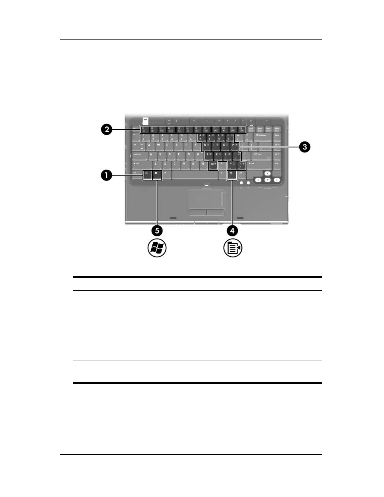
Keys
Component Description
1 fn key Combines with other keys and buttons
to perform system tasks. For example,
pressing fn+f7 decreases screen
brightness.*
2 Function keys (12) Perform system and application tasks.
When combined with fn, function keys
perform additional tasks as hotkeys.
†
3 Keypad keys (15) In Windows, can be used like the keys
on an external numeric keypad.
(Continued)
1–2 Hardware and Software Guide
Page 12

Hardware
Component Description
4 Windows applications key In Windows, displays a shortcut menu
for items beneath the pointer.
5 Windows logo key In Windows, displays the Windows
Start menu.
*The keys and buttons that can be combined with the fn key as hotkeys
include the esc and function keys.
†
For information about using hotkeys, refer to the “Hotkeys” section in
Chapter 2, “Keyboard and TouchPad.”
Hardware and Software Guide 1–3
Page 13
Hardware
TouchPad
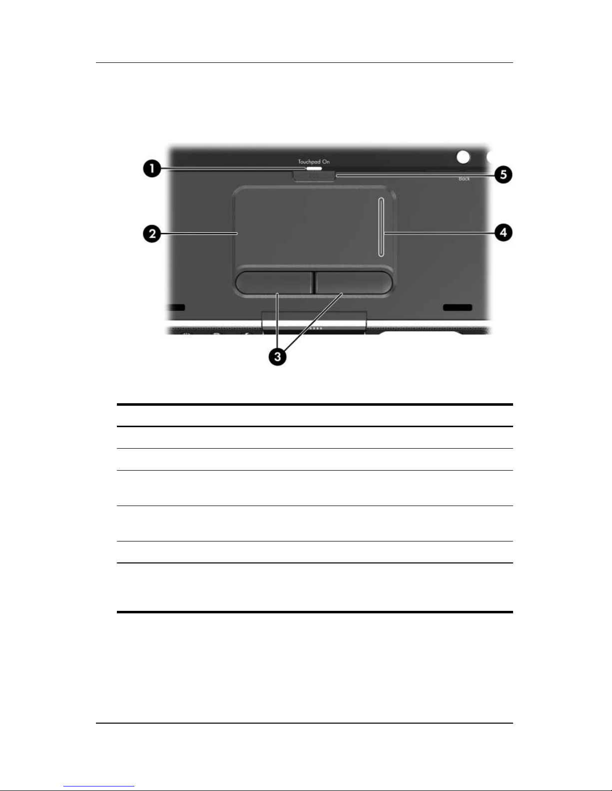
Component* Description
1 TouchPad light On: TouchPad is enabled.
2 TouchPad* Moves the pointer.
3 Left and right TouchPad
buttons*
4 TouchPad vertical scrolling
region*
Function like the left and right buttons
on an external mouse.
Scrolls upward or downward.
5 TouchPad button Enables/disables the TouchPad.
*This table describes default settings. For information about changing the
functions of these TouchPad components, refer to the “
Preferences” section in Chapter 2, “Keyboard and TouchPad.”
Setting TouchPad
1–4 Hardware and Software Guide
Page 14
Power Controls
Hardware
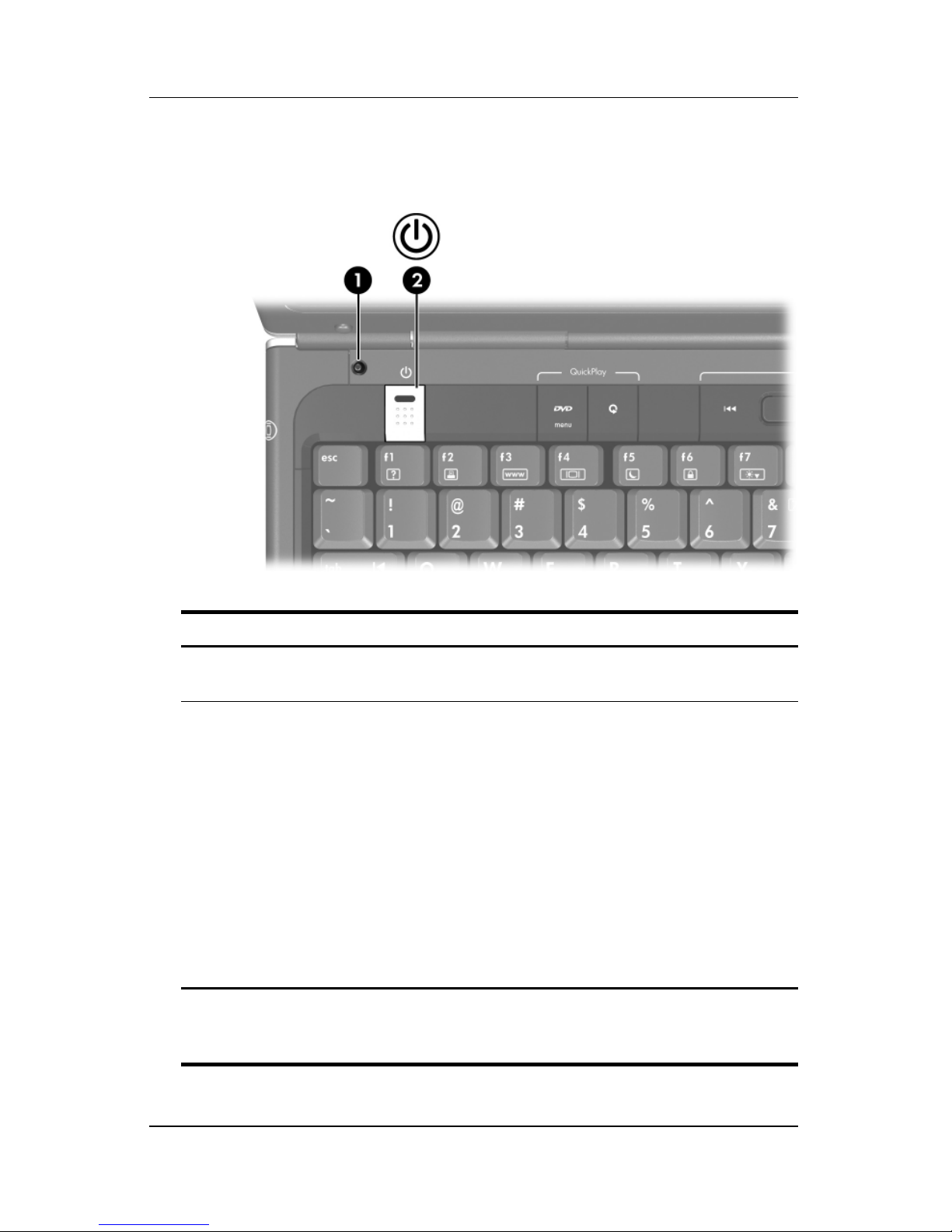
Component Description
1 Display switch* Initiates standby when the computer is
closed.*
2 Power button* When the computer is
■ Off, press to start the computer in Windows.
■ On, briefly press to initiate hibernation.
■ In standby, briefly press to resume from
standby into Windows.
■ In hibernation, briefly press to restore from
hibernation into Windows.
If the system has stopped responding
✎
and Windows shutdown procedures
cannot be used, press and hold for at
least 4
*This table describes default settings. For information about changing the
function of the display switch or
Power Preferences” section in Chapter 3, “Power.”
power button, refer to the “Setting Other
seconds to turn off the computer.
Hardware and Software Guide 1–5
Page 15
Hardware
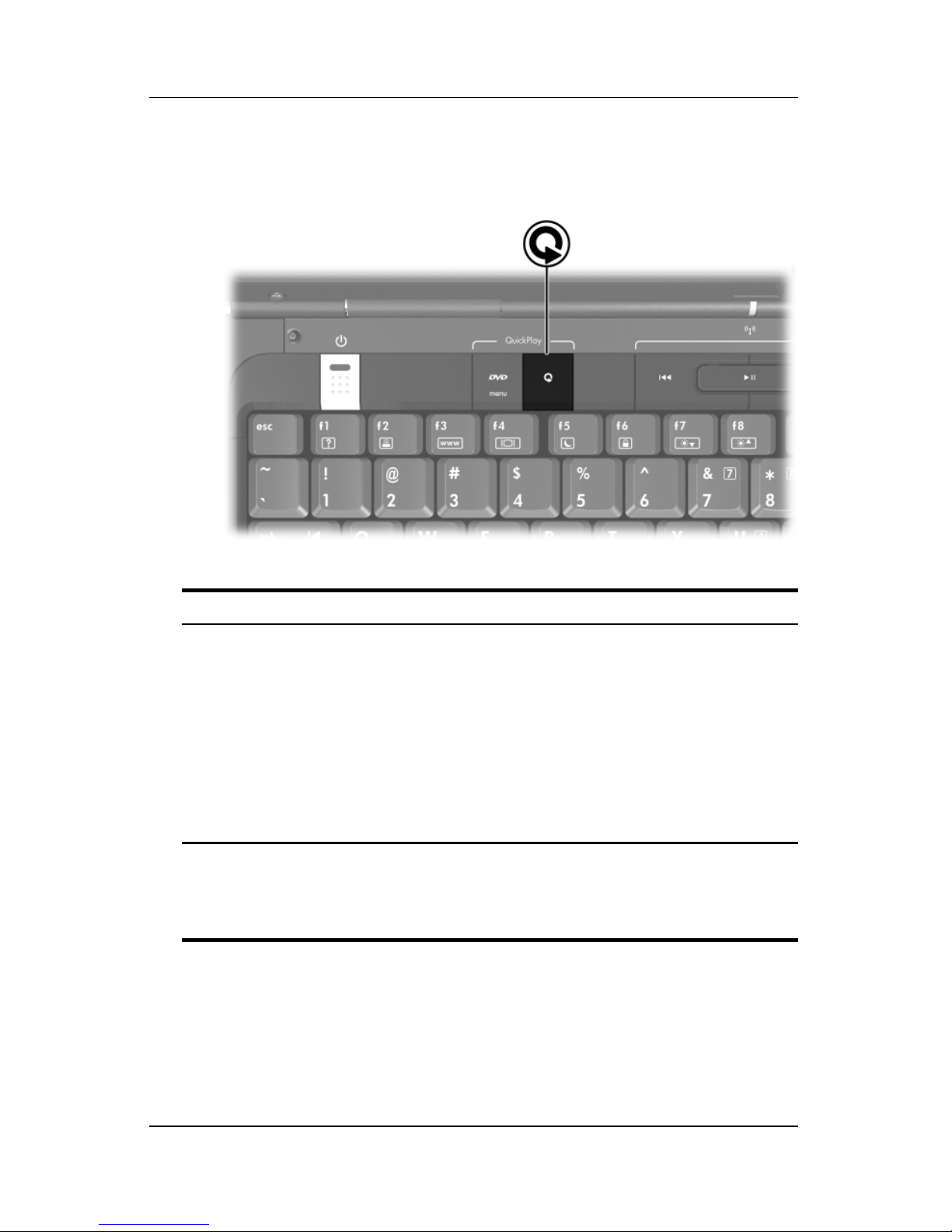
DVD Button
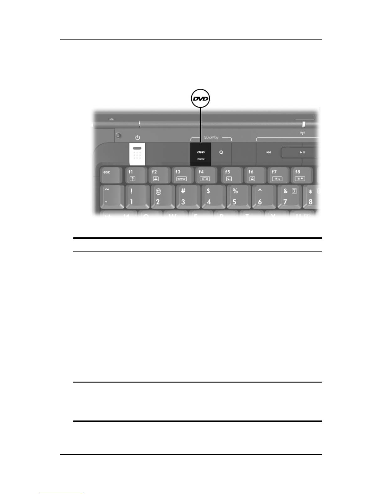
Component Description
DVD button When the computer is
■ On, opens the default DVD application
to start a DVD in the optical drive.
■ Off, opens QuickPlay to start a DVD in
the optical drive. If the QuickPlay
software is not installed, the computer
starts in Windows.
■ In hibernation, opens QuickPlay to start
a DVD in the optical drive. If the
QuickPlay software is not installed, the
computer resumes from hibernation.
Refer to the QuickPlay online Help
✎
for details on using QuickPlay.
*The function of the DVD button in Windows can be changed. For
instructions, refer to the “
section in Chapter 8, “Software Updates and Recovery and System
Software.”
Quick Launch Buttons (Select Models Only)”
1–6 Hardware and Software Guide
Page 16
Media Button
Hardware
Component Description
Media button If QuickPlay is installed, opens QuickPlay to
start a CD in the optical drive or a music file
on the hard drive.
If QuickPlay is not installed and the
computer
■ On, Opens the default media player to
start a CD in the optical drive or a music
file on the hard drive.
■ Off or in hibernation, no function.
*The function of the media button in Windows can be changed. For
instructions, refer to the “
section in Chapter 8, “Software Updates and Recovery and System
Software.”
Quick Launch Buttons (Select Models Only)”
is
Hardware and Software Guide 1–7
Page 17
Hardware
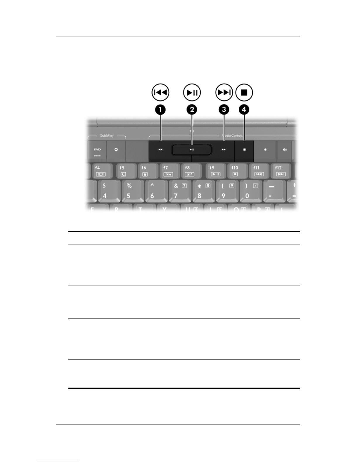
Media Controls—Media Activity Buttons
Component Description
1 Previous/Rewind button When a disc is playing in the optical drive:
■ Press to play the previous track or
chapter.
■ Press fn+this button to rewind.
2 Play/Pause button When a disc is in the optical drive and is
■ Not playing, press to play the disc.
■ Playing, press to pause the disc.
Next/Fast Forward button When a disc is playing in the optical drive:
3
■ Press once to play the next track or
chapter.
■ Press fn+this button to fast forward.
Stop button When a disc is playing in the optical drive,
4
press to stop the current disc activity,
such as fast forwarding, rewinding, etc.
1–8 Hardware and Software Guide
Page 18
Hardware
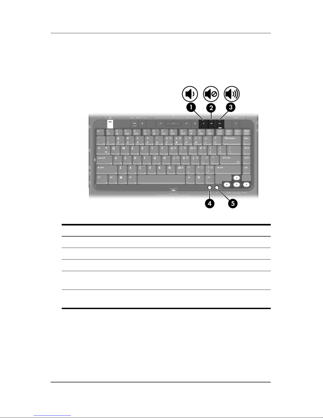
Media Controls—Volume, Back and OK
Buttons
Component Description
1 Volume down button Decreases system volume.
2 Volume mute button Mutes or restores volume.
3 Volume up button Increases system volume.
4 back button Emulates the Back button on the
Microsoft Internet Explorer toolbar.
5 ok button Selects an item you have chosen on
the screen.
Hardware and Software Guide 1–9
Page 19
Hardware
Lights
Component Description
1 Caps lock light On: Caps lock is on.
Power light* On: Computer is turned on.
2
Blinking: Computer is in standby.
Off: Computer is off.
3 Mute light On: Volume is muted.
4 Num lock light On: Num lock or the embedded numeric
keypad is
*There are 2 power lights. Both lights display the same information. The
light on the power button is visible only when the computer is open;
other power light is always visible on the front of the computer.
the
on.
1–10 Hardware and Software Guide
Page 20
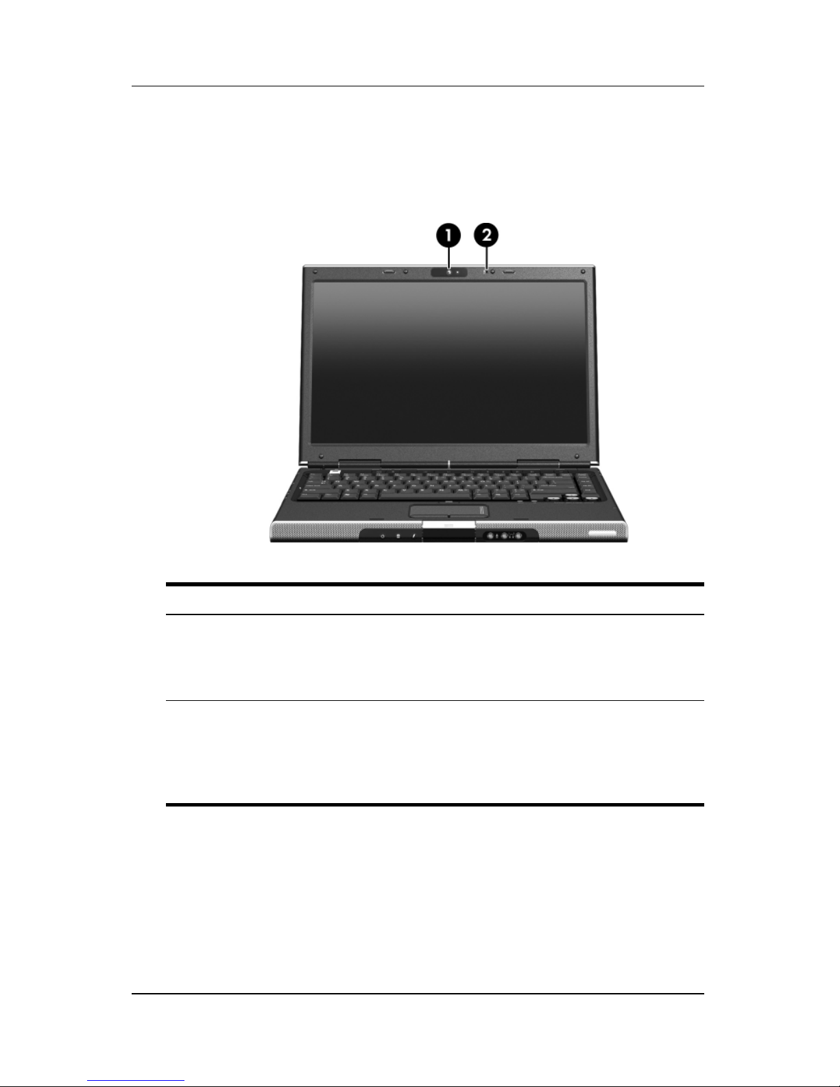
Camera and Microphone
Hardware
(Select
Models Only)
Component Description
1 Camera On select models, functions as a Web
camera. For more information, refer to the
Using the HP Webcam (Select Models
“
Only)” section in Chapter 4, “Multimedia.”
Microphone On select models, functions as an
2
embedded microphone. For more
information, refer to the “
Embedded Microphone (Select Models
Only)” section in Chapter 4, “Multimedia.
Using the
Hardware and Software Guide 1–11
Page 21
Hardware
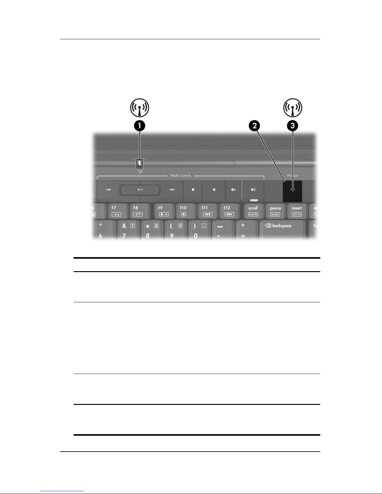
Wireless Lights and Button
(Select
Models Only)
Component Description
1 Wireless light* On: One or more internal wireless devices,
such as a wireless LAN device and/or a
Bluetooth® device, are turned on.
Wireless button Turns the wireless functionality on or off, but
2
does not create a wireless connection.
To establish a wireless connection, a
✎
wireless network must already be set
up. For information about establishing a
wireless connection, refer to Chapter
Wireless (Select Models Only).”
“
Wireless light* On: One or more internal wireless devices,
3
such as a WLAN and/or a Bluetooth device,
are turned on.
*There are 2 wireless lights. Both lights display the same information. The
light on the wireless button is visible only when the computer is open; the
other wireless light is always visible on the rear of the computer.
5,
1–12 Hardware and Software Guide
Page 22

Hardware
Wireless Antennae (Select Models Only)
Component Description
Antennae (2)* Send and receive wireless device signals.
Exposure to Radio Frequency
Å
Radiation
notices in your region, refer to
Regulatory, Safety, and Environmental
Notices
*The antennae are not visible from the outside of the computer. For optimal
transmission, keep the areas immediately around the
obstructions.
. For wireless regulatory
.
antennae free from
Hardware and Software Guide 1–13
Page 23
Hardware
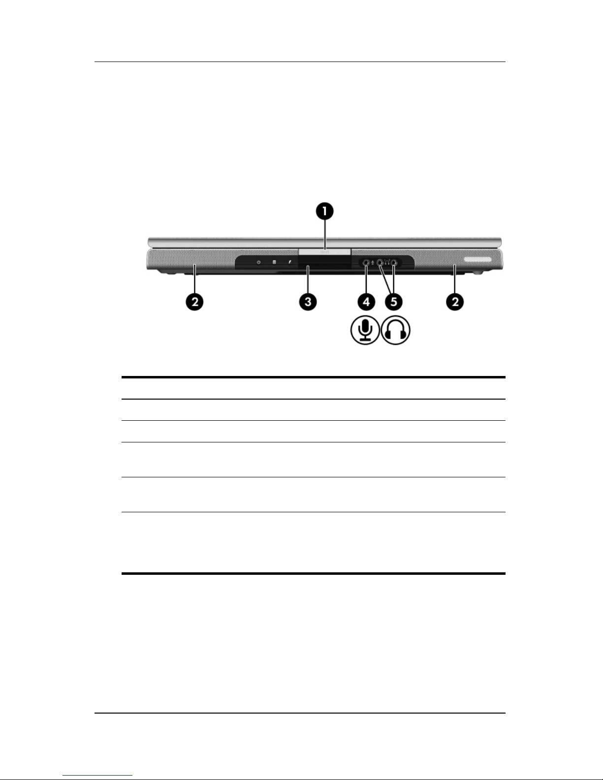
Front Components
Speakers, Jacks, Display Release Button
and
Infrared Lens
Component Description
1 Display release button Opens the computer.
2 Stereo speakers (2) Produce stereo sound.
Consumer Infrared lens Links the computer to an optional remote
3
control.
4 Audio-in
(microphone)
5 Audio-out (headphone)
jacks (2)
1–14 Hardware and Software Guide
jack
Connects an optional monaural (single
sound channel) microphone.
Connect optional headphones or
powered stereo speakers. Also connect
the audio function of an audio/video
device such as a television or
VCR.
Page 24
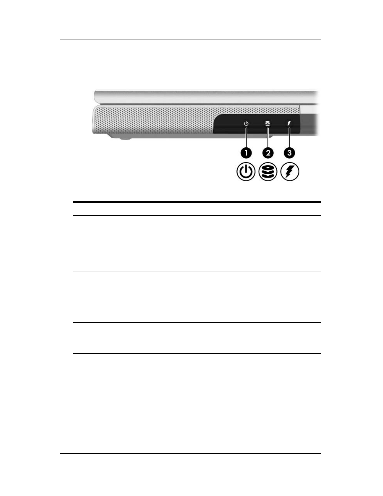
Lights
Component Description
Hardware
1 Power light* On: Computer is turned on.
Blinking: Computer is in standby.
Off: Computer is off.
2 IDE (Integrated Drive
Electronics) drive light
On or blinking: The internal hard drive
or an optical drive is being accessed.
3 Battery light On: The battery pack is charging.
Blinking: The battery pack has
reached a low-battery condition.
Off: The battery pack is fully charged
or not inserted.
*There are 2 power lights. Both lights display the same information. The
light on the power button is visible only when the computer is open; the
other power light is always visible on the front of the computer.
Hardware and Software Guide 1–15
Page 25
Hardware
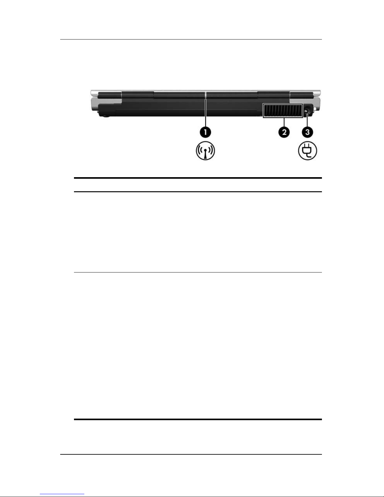
Rear Components
Component Description
Wireless light
1
(select
models only)*
2 Exhaust vent
On: An internal wireless device, such as a
wireless LAN device and/or a Bluetooth
device, is turned on.
To establish a wireless connection,
✎
a wireless network must already be
set up. For more information, refer
to Chapter
Models Only).”
†
Provides airflow to cool internal
components.
To prevent overheating, do not
Ä
obstruct vents. Use the computer
only on a hard, flat surface. Do not
allow another hard surface, such
as a printer, or a soft surf
as pillows or thick rugs or clothing,
to block the airflow.
The computer fan starts up
✎
automatically to cool internal
components and prevent
overheating. It is normal for the
internal fan to cycle on and off
during routine operation.
5, “Wireless (Select
ace, such
1–16 Hardware and Software Guide
(Continued)
Page 26

Hardware
Component Description
Power connector Connects the AC adapter cable.
3
*There are 2 wireless lights. Both lights display the same information. The
light on the wireless button is visible only when the computer is open; the
other wireless light is always visible on the rear of the computer.
†
The computer has 4 vents. This and all other vents are visible on the
bottom of the computer. One vent is also visible on the left side of the
computer.
Hardware and Software Guide 1–17
Page 27
Hardware
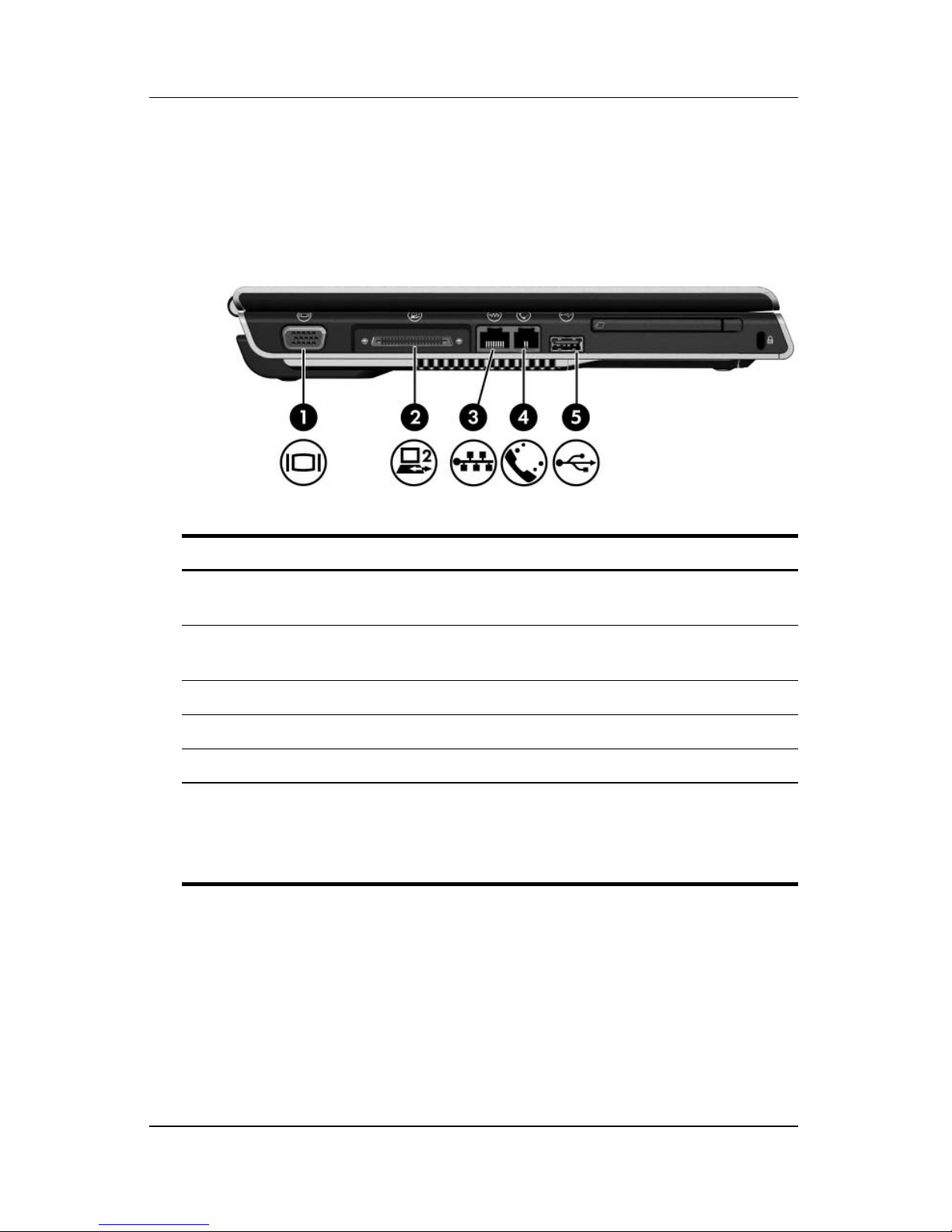
Left-Side Components
Ports and Jacks
Component Description
1 External monitor port Connects an optional VGA monitor or
projector.
Expansion port 2* Connects the computer to an optional
2
expansion product.
3 RJ-45 (network) jack Connects an optional network cable.
4 RJ-11 (modem) jack Connects the modem cable.
5 USB port
*For expansion port signal information, refer to the “Expansion Port
Input/Output Signals” section in “Appendix A.”
†
The computer has 3 USB ports. The other USB ports are on the right side
of the computer.
†
Connects an optional USB device.
†
1–18 Hardware and Software Guide
Page 28
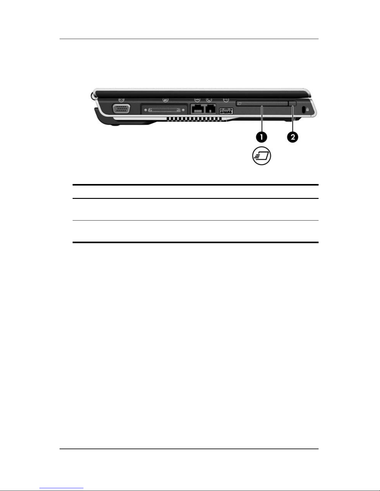
ExpressCard Slot and Button
Component Description
ExpressCard slot Supports optional ExpressCard/54 or
1
ExpressCard/34 cards.
Hardware
ExpressCard eject button Ejects an optional ExpressCard from
2
the ExpressCard slot.
Hardware and Software Guide 1–19
Page 29
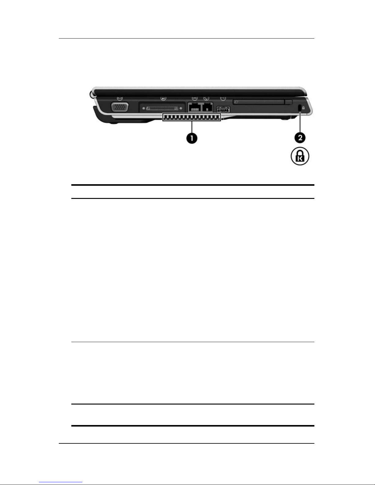
Hardware
Vent and Security Cable Slot
Component Description
1 Exhaust vent* Provides airflow to cool internal
components.
To prevent overheating, do not
Ä
obstruct vents. Use the computer
only on a hard, flat surface. Do not
allow another hard surface, such
as a printer, or a soft surface, such
as pillows or thick rugs or clothing,
to block the airflow.
The computer fan starts up
✎
automatically to cool internal
components and prevent
overheating. It is normal for the
internal fan to cycle on and off
during routine operation.
2 Security cable slot Attaches an optional security cable to the
computer.
The security cable is designed to
✎
act as a deterrent, but may not
prevent the computer from being
mishandled or stolen.
*The computer has 4 vents. This and all other vents are visible on the
bottom of the computer. One vent is also visible on the rear of the computer.
1–20 Hardware and Software Guide
Page 30
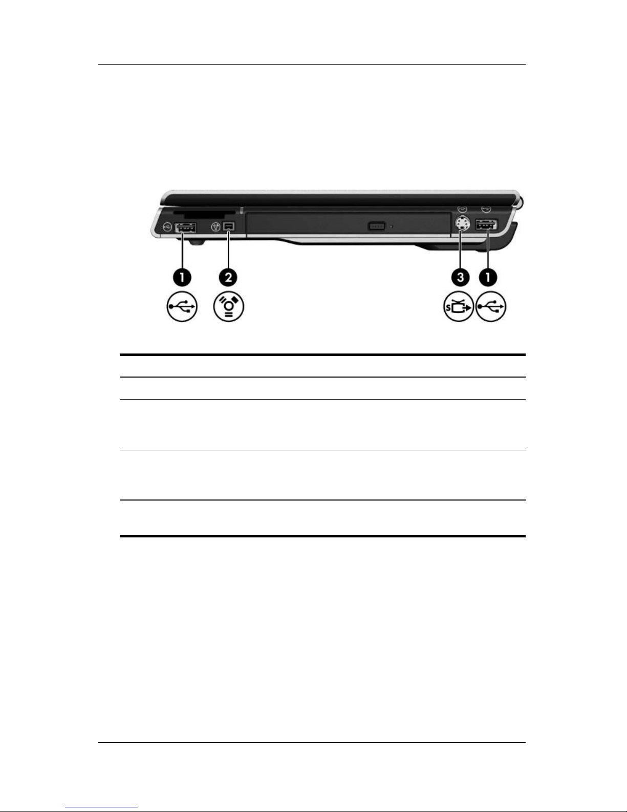
Right-Side Components
Ports and Jack
Hardware
Component Description
1 USB ports (2)* Connect optional USB devices.
2 1394 port Connects an optional 1394 device such
as a scanner, a digital camera, or a digital
camcorder.
3 S-Video–out jack Connects an optional S-Video device,
such as a television, VCR, camcorder,
projector, or video capture card.
*The computer has 3 USB ports. The other USB port is on the left side of
the computer.
Hardware and Software Guide 1–21
Page 31

Hardware
Digital Media Slot Components and
Optical
Component Description
Drive
1 Digital Media Slot Supports digital cards.*
2 Digital Media Slot light On: A digital card is being accessed.*
3 Optical drive
4
*The supported digital cards are Secure Digital (SD) Memory Card, Memory
Stick, Memory Stick Pro, xD-Picture Card, MultiMediaCard, and
SmartMedia (SM) card.
†
DVD/CD-RW Combo Drive—varies by computer model.
Media tray release button Opens the optical drive media tray.
The type of optical drive—for example, a DVD-ROM drive or a
†
Supports an optical disc.
1–22 Hardware and Software Guide
Page 32

Bottom Components
Mini Card and Memory Compartments
Hardware
Component Description
Memory
1
compartment
2 Mini Card
compartment
Contains 2 memory slots that support
replaceable memory modules. The number of
preinstalled memory modules varies by
computer model.
Holds an optional Mini Card device.
To prevent an unresponsive system and
Ä
the display of a warning message, install
only a Mini Card device authorized for
use in your computer by the
governmental agency that regulates
wireless devices in your country. If you
install a device and then receive a
warning message, remove the device to
restore computer functionality. Then
contact Customer Care. If the computer
is connected to the Internet, you can get
help by e-mail; or access Customer
Care telephone numbers through the
Help and Support Center.
Hardware and Software Guide 1–23
Page 33

Hardware
Bays, Battery Latch and Vents
Component Description
1 Battery bay Holds a battery pack.
2 Battery pack release
latch*
3 Exhaust vents (4)
†
Releases a battery pack from the
battery
Provide airflow to cool internal components.
Ä
✎
bay.
To prevent overheating, do not
obstruct vents. Use the computer
only on a hard, flat surface. Do not
allow another hard surface, such as
a printer, or a soft surface, such as
pillows or thick rugs or clothing, to
block the airflow.
The computer fan starts up
automatically to cool internal
components and prevent
overheating. It is normal for the
internal fan to cycle on and off during
routine operatio
n.
4 Hard drive bay Holds the internal hard drive.
*Battery packs vary by model.
†
The computer has 4 vents. One vent is also visible on the left side of
computer, and one vent is also visible on the rear of the computer.
the
1–24 Hardware and Software Guide
Page 34

Additional Components
Hardware
The components included with your computer vary by region,
country, computer model, and the optional hardware you
purchased. The following sections identify the standard external
components included with most computer models.
Hardware
Component Description
1 Battery pack Powers the computer when the computer
is not connected to external
power.
2 AC adapter Converts AC power to DC power.
3 Power cord Connects an AC adapter to an AC outlet.
Power cords and adapters vary in appearance by region and
✎
country. Battery packs vary by model.
Hardware and Software Guide 1–25
Page 35

Hardware
Optical Discs
The computer includes software provided on optical discs (CDs
and DVDs) that is not yet installed, as well as backup discs of
software that is preinstalled on the computer.
Locate the plastic bag included with the computer and remove the
discs that display the sticker below.
Depending on how you plan to use your computer, you may want
to install the software contained on these discs now.
For instructions on inserting and removing an optical disc, refer
CD and DVD Procedures,” in Chapter 4, “Multimedia.”
to “
1–26 Hardware and Software Guide
Page 36

Labels
The labels affixed to the computer provide information you
may
internationally with the computer.
The appearance and position of labels varies by model.
✎
■ Service tag—Provides the product name, serial number (s/n),
■ Microsoft Certificate of Authenticity—Contains the
Hardware
need when you troubleshoot system problems or travel
and other specifics about the computer. Have this information
available when you contact Customer Care. The service tag
label is affixed to the bottom of the computer.
Microsoft Windows Product Key. You may need the Product
Key to update or troubleshoot the operating system. This
certificate is affixed to the bottom of the computer.
■ Regulatory label—Provides regulatory information about the
computer. The regulatory label is affixed to the bottom of the
computer.
■ Modem approval label—Provides regulatory information
about the modem and lists the agency approval markings
required by some of the countries in which the modem has
been approved for use. You may need this information when
traveling internationally. The modem approval label is affixed
on the inside of the memory module compartment cover.
■ Wireless certification label(s)—Provide information about
optional wireless devices available on select models, and the
approval markings of some of the countries in which the
devices have been approved for use. An optional device may
be a wireless local area network (WLAN) device or a
Bluetooth
more wireless devices, one or more certification labels are
included with the computer. You may need this information
when traveling internationally. Wireless certification labels
are affixed on the inside of the Mini Card compartment cover.
® device. If the computer model includes one or
Hardware and Software Guide 1–27
Page 37

✎
2
Keyboard and TouchPad
This chapter provides information on the functions and features
of components when used in Microsoft® Windows®. If using
QuickPlay (select models only), the functionality of some
components may differ. Refer to the HP QuickPlay online Help
for more information.
Hardware and Software Guide 2–1
Page 38

Keyboard and TouchPad
TouchPad
Identifying TouchPad Components
The TouchPad includes the following components:
1 TouchPad light 4 TouchPad vertical scrolling region
2 TouchPad 5 TouchPad button
3 Left and right
TouchPad buttons
2–2 Hardware and Software Guide
Page 39

Using the TouchPad
In Windows the TouchPad provides the navigation, selection, and
scroll functions of an optional external mouse.
In Windows:
■ To move the pointer, slide your finger across the TouchPad
surface in the direction you want to move the pointer.
■ To execute the click functions of the left or right button on
an
external mouse, press the left or right TouchPad button.
■ To scroll, place your finger onto the scrolling region, and then
slide your finger upward or downward. (Sliding your finger
from the TouchPad to the scrolling region without first lifting
your finger from the TouchPad and then placing it on the
scrolling region will not activate the scrolling region.)
Keyboard and TouchPad
■ To enable or disable the TouchPad, press the TouchPad
button. When the TouchPad is enabled, the TouchPad light
on.
is
The TouchPad is enabled when the computer is turned on. If
you work with keystrokes rather than mouse actions, you may
prefer to disable the TouchPad to prevent accidental
TouchPad activity.
Setting TouchPad Preferences
In the Windows Mouse Properties window you can
■ Adjust basic pointing device settings such as click speed,
pointer speed and shape, and mouse trails.
■ Configure the right and left TouchPad buttons for
right-handed or left-handed use. These buttons are set
default for right-handed use.
by
Hardware and Software Guide 2–3
Page 40

Keyboard and TouchPad
To access the Mouse Properties window:
» Select Start > Control Panel > Printers and Other
Hardware > Mouse.
In the TouchPad Properties window you can access additional
TouchPad preferences.
To access the TouchPad Properties window, use the TouchPad to
select Start > Control Panel > Printers and Other Hardware >
Mouse > Device Settings, and then select the Settings button. (If
you follow this path using an optional external mouse, the
TouchPad Properties window may be unavailable.)
Among the preferences available in the TouchPad Properties
window are
■ TouchPad Tapping, which enables you to tap the TouchPad
once to select an item or twice to double-click an item.
To access TouchPad Tapping settings, select Tapping .
■ Edge Motion, which sets the TouchPad to continue cursor
movement when your finger reaches the edge of the
TouchPad.
To access Edge Motion settings, select Pointer Motion.
■ Long Distance Scrolling, which sets the scrolling region to
continue scrolling when your finger reaches the end of the
scrolling region.
To access Long Distance Scrolling, select Virtual Scrolling.
■ PalmCheck, which helps keep the TouchPad from being
accidentally activated while you are using the keyboard.
To access PalmCheck, select Sensitivity.
2–4 Hardware and Software Guide
Page 41

Hotkeys
Identifying Hotkeys
Hotkeys are preset combinations of the fn key 1, the esc key 2,
or one of the function keys 3.
The icons on the f1 through f12 function keys represent their
hotkey functions.
Keyboard and TouchPad
Hardware and Software Guide 2–5
Page 42

Keyboard and TouchPad
Hotkey Quick Reference
The following table identifies the default hotkey functions. The
function of the
refer to
the “Setting Other Power Preferences” section in
Chapter 3, “Power.”
Default Function Hotkey
Open the Help and Support Center. fn+f1
Open the Print Options window. fn+f2
Open the default Internet browser. fn+f3
Switch the image among displays. fn+f4
Initiate standby. fn+f5
fn+f5 hotkey can be changed. For instructions,
Initiate QuickLock. fn+f6
Decrease screen brightness. fn+f7
Increase screen brightness. fn+f8
Play, pause, or resume an audio CD or DVD. fn+f9
Stop an audio CD or DVD. fn+f10
Play the previous track or chapter on an audio CD
DVD.
or
Play the next track or chapter on an audio CD
DVD.
or
Display system information. fn+esc
Clear the system information display esc
fn+f11
fn+f12
2–6 Hardware and Software Guide
Page 43

Keyboard and TouchPad
Using Hotkey Procedures
Using Hotkeys on the Internal Keyboard
To use a hotkey command on the computer keyboard, use either
of the following procedures:
■ Briefly press fn, and then briefly press the second key of
hotkey command.
the
■ Press and hold down fn, briefly press the second key of
hotkey command, and then release both keys at the
the
time.
same
Using Hotkey Commands
Open the Help and Support Center (fn+f1)
In Windows the fn+f1 hotkey opens the Help and Support Center.
In addition to providing information about your Windows
operating system, the Help and Support Center provides
■ Information about your computer, such as model and serial
number, installed software, hardware components, and
specifications.
■ Answers to questions about using your computer.
■ Tutorials to help you learn to use computer and Windows
features.
■ Updates for your Windows operating system, drivers, and the
software provided on your computer.
■ Checkups for computer functionality.
■ Automated and interactive troubleshooting, repair solutions,
and system recovery procedures.
■ Links to HP support specialists.
Hardware and Software Guide 2–7
Page 44

Keyboard and TouchPad
Open the Print Options Window (fn+f2)
In Windows the fn+f2 hotkey opens the Print Options window of
the active Windows application.
Open the Default Internet Browser (fn+f3)
In Windows the fn+f3 hotkey opens the default Internet browser.
■ Until you have set up your Internet or network services, the
fn+f3 hotkey opens the Windows Internet Connection Wizard.
■ After you have set up your Internet or network services and
your Web browser home page, you can use the
quickly access your
home page and the Internet.
fn+f3 hotkey to
Switch Image Among Displays (fn+f4)
The fn+f4 hotkey switches the image among display devices
connected to the system. For example, if a monitor is
connected
to the computer through the monitor port, each time you press the
fn+f4 hotkey the image switches among the computer display, the
monitor display, and a simultaneous display on both the computer
and the monitor.
Most external monitors receive video information from the
computer using the external VGA video standard. The
fn+f4
hotkey can also toggle images among other devices receiving
video information from the computer.
2–8 Hardware and Software Guide
Page 45

The following video transmission types, with examples of devices
that use them, are supported by the
■ LCD (computer display)
■ External VGA (most external monitors)
■ S-Video (televisions, camcorders, VCRs, and video capture
cards with S-Video–in jacks)
■ Composite video (televisions, camcorders, VCRs, and video
capture boards with composite video-in jacks)
Composite video devices can be connected to the system only
✎
by using an HP expansion product.
Initiate Standby (fn+f5)
Keyboard and TouchPad
fn+f4 hotkey:
The fn+f5 hotkey is set by default to initiate standby.
When standby is initiated, your work is stored in random access
memory (RAM), the screen is cleared, and power is conserved.
While the computer is in standby, the power lights blink.
■ To initiate standby, the computer must be on. If the computer
is in hibernation, you must restore from hibernation before
you can initiate standby.
■ To resume from standby, briefly press the power button, use
the TouchPad, press any key on the keyboard, or press a
TouchPad button. To restore from hibernation, briefly press
the power button.
The function of the fn+f5 hotkey can be changed. For example,
you can set the
fn+f5 hotkey to initiate hibernation instead of
standby. In all Windows operating system windows, references to
the sleep button apply to the
fn+f5 hotkey.
For information about changing the function of the fn+f5 hotkey,
refer to the “
Setting Other Power Preferences” section in
Chapter 3, “Power.”
For more information about using standby and hibernation, refer
to Chapter
Hardware and Software Guide 2–9
3, “Power.”
Page 46

Keyboard and TouchPad
Initiate QuickLock (fn+f6)
In Windows the fn+f6 hotkey initiates the QuickLock security
feature.
QuickLock protects your work by displaying the operating
system Log On window. While the Log On window is displayed,
the computer cannot be accessed until a Windows user password
or a Windows administrator password is entered.
Before you can use QuickLock, you must set a Windows user
password or a Windows administrator password. For instructions,
refer to the Help and Support Center.
To use QuickLock, press fn+f6 to display the Log On window and
lock the computer. Then follow the instructions on the screen to
enter your Windows user password or your Windows
administrator password and access the computer.
For information about combining Windows passwords with HP
passwords, refer to Chapter 6, “
Security.”
Decrease Screen Brightness (fn+f7)
The fn+f7 hotkey decreases the brightness of the computer screen.
The longer you hold down the
fn+f7 hotkey, the more the screen
dims. Decreasing screen brightness conserves power.
To increase screen brightness:
» Press the fn+f8 hotkey.
Increase Screen Brightness (fn+f8)
The fn+f8 hotkey increases the brightness of the computer
screen.
the
To decrease screen brightness:
The longer you hold down the fn+f8 hotkey, the more
screen brightens.
» Press the fn+f7 hotkey.
2–10 Hardware and Software Guide
Page 47

Keyboard and TouchPad
Media Activity Hotkeys (fn+f9 through fn+f12)
The following 4 media activity hotkeys control the play of an
a DVD.
✎
audio CD or
To control the play of a video CD, use the media activity controls
in your Windows video CD player application.
You can also control the play of an audio CD, a DVD, a video
CD, or an MP3 file by using the media activity buttons on your
computer.
The first 4 media control buttons control media activity. The
last 3 media control buttons control volume.
The media activity buttons are described in the “Using the Media
Activity Buttons” section in Chapter 4, “Multimedia.”
Play, Pause or Resume an Audio CD or a DVD
(fn+f9)
■ If the audio CD or the DVD is not playing, press the fn+f9
hotkey to begin or resume the play.
■ If the audio CD or the DVD is playing, press the fn+f9 hotkey
to pause the play.
Stop an Audio CD or a DVD (fn+f10)
The fn+f10 hotkey stops the play of an audio CD or a DVD.
You must stop a CD or DVD that is playing before you can
remove it from the optical drive. For more information about
inserting or removing a CD or DVD, refer to the “
Procedures” section in Chapter 4, “Multimedia.”
CD and DVD
Hardware and Software Guide 2–11
Page 48

Keyboard and TouchPad
Play Previous Track or Chapter of an
Audio CD or a DVD (fn+f11)
The fn+f11 hotkey plays the previous track of an audio CD or the
previous chapter of a DVD that is playing.
Play Next Track or Chapter of an Audio CD
or a DVD (fn+f12)
The fn+f12 hotkey plays the next track of an audio CD or the next
chapter of a DVD that is playing.
Display System Information (fn+esc)
The fn+esc hotkey displays information about system hardware
components and firmware version numbers.
In the Windows fn+esc display, the version of the system BIOS
(basic input-output system) is displayed as the BIOS date. On
some computer models, the BIOS date is displayed in decimal
format. The BIOS date is sometimes called the system ROM
version number.
For information about updating the system ROM, refer to the
Software Updates” section in Chapter 8, “Software Updates and
“
Recovery and System Software.”
To clear the fn+esc display:
» Press esc.
2–12 Hardware and Software Guide
Page 49

Keyboard and TouchPad
Media Menu Controls Buttons
The buttons above the keyboard that are labeled media controls
are described in other places in this guide. These buttons are
identified in the following illustration. Links to information about
these buttons are provided later in this section.
1 DVD button 3 Media activity controls
2 Volume buttons 4 Media button
Hardware and Software Guide 2–13
Page 50

Keyboard and TouchPad
Finding DVD and Media Button Information
To fi nd
■ A summary of DVD and media button functions, refer to the
DVD Button” and “Media Button” sections in Chapter 1,
“
“Hardware.”
■ Information about DVD and media button functions in
Windows, refer to “
Chapter 4, “Multimedia.”
■ Information about changing the Windows functions of the
DVD and media button, refer to the “
(Select Models Only)” section in Chapter 8, “Software
Updates and Recovery and System Software.”
Using the QuickPlay Buttons” in
Quick Launch Buttons
Finding Media Activity Button Information
To find information about using the media activity buttons in
Windows, refer to the “
Using the Media Activity Buttons”
section in Chapter 4, “Multimedia.”
Finding Volume Button Information
To find information about using the volume buttons in Windows,
refer to the “
“Multimedia.”
Volume Controls” section in Chapter 4,
2–14 Hardware and Software Guide
Page 51

Keyboard and TouchPad
Keypads
You can do keypad work with your computer by using the keypad
embedded in the computer keyboard or by connecting an optional
external keypad. The keypad embedded in the computer keyboard
is called the embedded numeric keypad.
The embedded numeric keypad cannot be used while an external
numeric keypad is connected to the computer.
Using the Embedded Numeric Keypad
The embedded numeric keypad consists of 15 keys that can be
used like the keys on an external numeric keypad. When the
embedded numeric keypad is turned on, each keypad key
performs the functions indicated by the icon in the upper-right
corner of the key.
Hardware and Software Guide 2–15
Page 52

Keyboard and TouchPad
Turning the Embedded Numeric Keypad
On
and Off
When the embedded numeric keypad is off, press fn+num lk 1 to
turn the
When the embedded numeric keypad is on, press fn+num lk to turn
the keypad
keypad on. The num lock light 2 is turned on.
off. The num lock light is turned off.
2–16 Hardware and Software Guide
Page 53

Keyboard and TouchPad
Switching the Functions of Keypad Keys
You can temporarily switch the functions of an embedded
numeric keypad key between its standard function and its keypad
function.
■ To use a key on the keypad as a keypad key while the
keypad
■ To use a key on the keypad as a standard key while the
keypad is turned on:
❏ Press and hold fn to type with the key in lowercase.
❏ Press and hold fn+shift to type with the key in uppercase.
Releasing fn returns a keypad key to its set function. For example,
a keypad key returns to its keypad function if the keypad is turned
on or to its standard function if the keypad is turned off.
is turned off, press and hold fn while pressing the key.
Using an External Numeric Keypad
The embedded numeric keypad cannot be used while an
✎
optional external numeric keypad is connected to the computer.
Most keys on most external numeric keypads function differently
depending on whether num lock mode is on or off. For example:
■ When num lock mode is on, most keypad keys type numbers.
■ When num lock mode is off, most keypad keys function like
the arrow, page up, or page down keys.
Hardware and Software Guide 2–17
Page 54

Keyboard and TouchPad
Turning Num Lock Mode On and Off
As
You Work
To turn num lock mode on or off on an external numeric keypad
as you work, press the
not on the computer.
■ When an external numeric keypad is turned on and is in num
lock mode, the num lock light on the computer is on.
■ When an external numeric keypad is turned off or is turned on
with num lock mode turned off, the num lock light on the
computer is off.
num lk key on the external numeric keypad,
2–18 Hardware and Software Guide
Page 55

✎
3
Power
This chapter provides information on the functions and
features of components when used in Microsoft Windows. If
using QuickPlay (select models only), the functionality of
some components may differ. Refer to the HP QuickPlay
online Help for more information.
Hardware and Software Guide 3–1
Page 56

Power
Power Sources
Selecting a Power Source
Use the following table to select a recommended power source
for the way you plan to use the computer.
Task Recommended Power Source
Work in most software
applications
Charge or calibrate a
battery pack in the
computer
Install or modify
system software or
write to an optical disc
■ Charged battery pack in the computer
■ External power supplied through one of the
following devices:
❐ AC adapter
❐ Optional expansion product
❐ Optional power adapter
External power supplied through one of the
following devices:
■ AC adapter
■ Optional expansion product
■ Optional power adapter
Do not charge the computer battery
Å
pack onboard aircraft. Charging the
battery pack may damage aircraft
electronic systems.
External power supplied through one of the
following devices:
■ AC adapter
■ Optional expansion product
3–2 Hardware and Software Guide
■ Optional power adapter
Page 57

Connecting the AC Adapter
WARNING: To reduce the risk of electric shock or damage to the
Å
equipment:
■ Plug the power cord into an AC outlet that is easily accessible at all
times.
■ Disconnect power from the computer by unplugging the power cord
from the AC outlet (not by unplugging the power cord from the
computer).
■ If provided with a 3-pin attachment plug on the power cord, plug
the cord into a grounded (earthed) 3-pin outlet. Do not disable the
power cord grounding pin; for example, by attaching a 2-pin
adapter. The grounding pin is an important safety feature. It is
possible to receive an electric shock from a system that is not
properly grounded.
Power
To connect the computer to external AC power:
1. Plug the AC adapter into the power connector 1 on the
computer.
2. Plug the power cord into the AC adapter 2.
3. Plug the other end of the power cord into an AC outlet 3.
Hardware and Software Guide 3–3
Page 58

Power
Switching Between Battery and
External
The computer runs on external power whenever external power
is
inserted battery pack. External power can be supplied through
an
combination power adapter.
Because the computer switches between battery power and
external power according to the availability of external power:
■ If the computer is running on battery power and you connect
■ If the computer is running on external power (and contains a
Power
available to the computer. This conserves the charge in an
AC adapter, an optional expansion product, or optional
the computer to external power, the computer switches to
external power.
charged battery pack) and you disconnect the computer from
external power, the computer switches to battery power.
Displaying the Power Meter Icon
✎
When the computer is running Windows, a Power Meter icon is
displayed by default in the notification area, at the far right of the
taskbar. The Power Meter icon changes shape whenever the
power source changes between battery power and external power.
If the Power Meter icon is not displayed in the notification area
when the
1. Select Start > Control Panel > Performance and
2. Click the Advanced tab.
3. Select the Always show icon on the taskbar check box.
4. Click OK.
If you cannot see an icon you have placed in the notification
area (at the far right of the taskbar), the icon may be hidden.
Click the arrow in the notification area to view hidden icons.
computer is running Windows:
Maintenance
> Power Options.
3–4 Hardware and Software Guide
Page 59

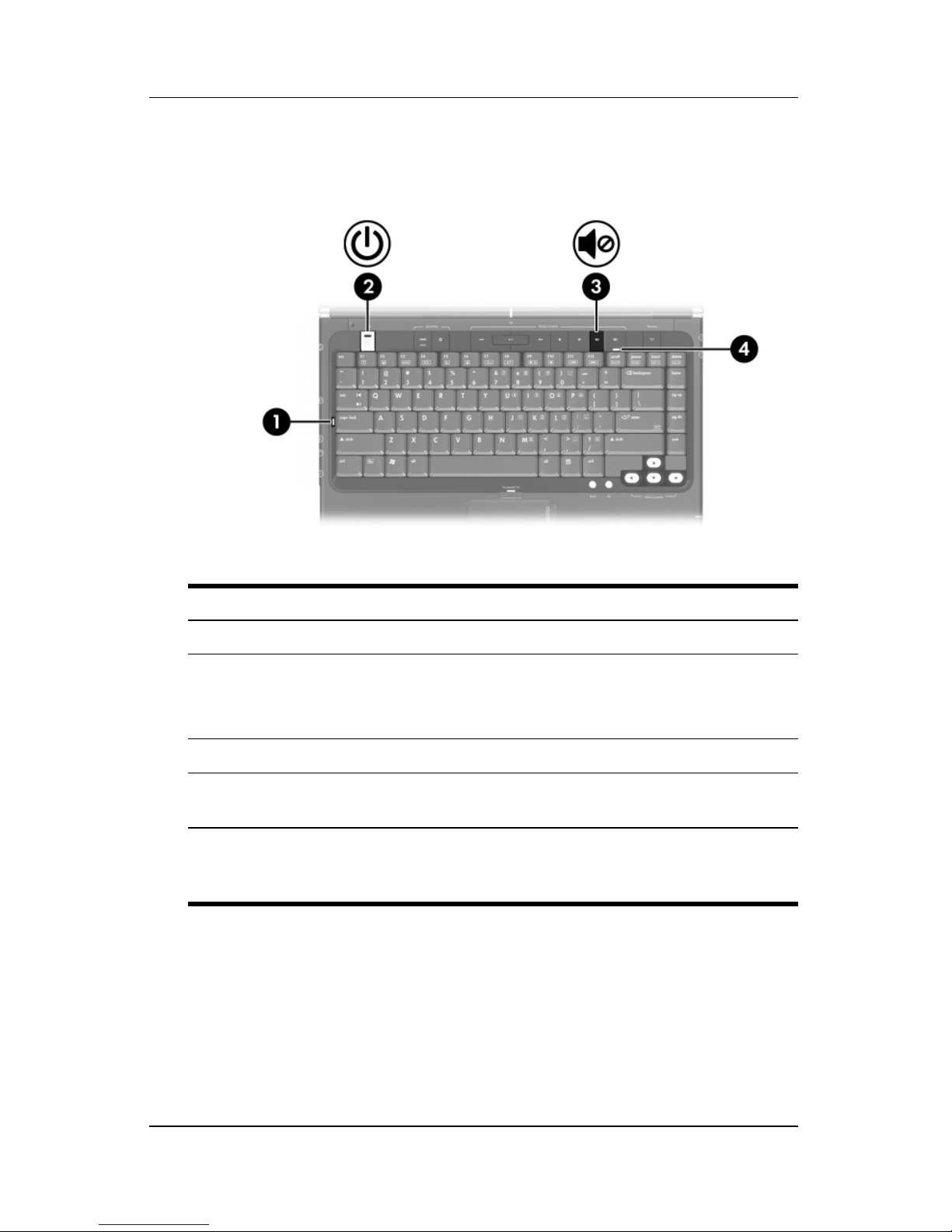
Power Control and Light Locations
This illustration is provided as a quick reference to the locations
of the power controls and lights on the computer.
The function of each of these items is summarized in Chapter 1,
Hardware.” Instructions for using these items are provided in
“
this chapter.
1 Display switch 5 DVD button
2 Power button 6 Media button
3 Power light 7 Power light
4 fn+f5 hotkey 8 Battery light
Power
There are 2 power lights. Both display the same information. The
✎
Hardware and Software Guide 3–5
light on the power button is visible only when the computer is
open; the other power light is always visible on the front of the
computer.
Page 60

Power
Standby, Hibernation and Shutdown
Overviews
CAUTION: To avoid a complete battery discharge, do not leave your
Ä
Standby
computer in standby for extended periods. Connect the computer to an
external power source.
Standby reduces power to system components that are not in use.
When standby is initiated, your work is stored in random access
memory (RAM), the screen is cleared, and the power lights blink.
When you resume from standby, your work is returned to the
screen where you left off.
CAUTION: To reduce the risk of information loss, save your work
Ä
before initiating standby.
Hibernation
CAUTION: If the configuration of the computer system is changed during
Ä
hibernation, it may not be possible to resume from hibernation. When the
computer is in hibernation:
■ Do not connect or disconnect the computer from an expansion
product.
■ Do not add or remove any memory modules.
■ Do not insert remove or replace any optical drives.
■ Do not connect or disconnect an external device.
■ Do not insert or remove an external media card such as an
ExpressCard or Digital Media Slot card.
3–6 Hardware and Software Guide
Page 61

Ä
Power
Hibernation saves your work to a hibernation file on the hard
drive and then shuts down the computer. When hibernation is
complete, the power lights are turned off. When you restore from
hibernation, your work is returned to the screen where you left
off. If a power-on password has been set, the password must be
entered to restore from hibernation. Restoring from hibernation
takes a little longer than resuming from standby but is much faster
than returning to your place manually after restarting the
computer.
CAUTION: To reduce the risk of information loss, save your work
before initiating hibernation.
When the computer is running on battery power, hibernation is
initiated by default after 30 minutes of computer inactivity or
whenever the computer reaches a critical low-battery condition.
Determining Whether the Computer Is Off
in Hibernation
or
To determine whether the computer is turned off or in
hibernation, press the power button.
■ If the computer is in hibernation, the computer restores from
hibernation and your work is returned to the screen.
■ If the computer is off, Windows loads.
Hardware and Software Guide 3–7
Page 62

Power
Enabling or Disabling Hibernation
Hibernation is enabled by default but can be disabled. To prevent
loss of work when the computer is in Windows and reaches a
critical low-battery condition, disable hibernation only during a
battery pack calibration.
To be sure that hibernation is enabled:
» Select Start > Control Panel > Performance and
Maintenance > Power Options icon
hibernation is enabled, the Enable hibernation check box is
selected.
To set the time interval after which the system initiates
hibernation:
1. Select Start > Control Panel > Performance and
Maintenance > Power Options.
> Hibernate tab. If
2. Click one of the intervals in the System hibernates list.
Leaving Your Work
If you are working in Windows and plan to resume shortly—
Initiate standby for shorter times and hibernation for longer times
or for power conservation. The amount of time a battery pack can
support standby or hibernation or hold a charge varies by
computer configuration and the condition of the battery pack.
Standby requires more power than hibernation.
If you plan to resume within 2 weeks—Shut down the computer
from Windows. If possible, connect the computer to external
power to keep an inserted battery pack fully charged.
3–8 Hardware and Software Guide
Page 63

Power
If the computer will be unused and disconnected from external
power for more than 2 weeks—Shut down the computer from
Windows. To extend the life of an inserted battery pack, remove
the battery pack and store it in a cool, dry location. For
information about storing the battery pack, refer to the “
Storing a
Battery Pack” section later in this chapter.
If an external power supply is uncertain, for example, during an
electrical storm or low-battery condition— Take one of the
following actions:
■ Save your work, and then initiate standby.
■ Save your work, and then initiate hibernation.
■ Shut down the computer.
Hardware and Software Guide 3–9
Page 64

Power
Interference with Drive Media and Bluetooth
Communication (Select Models Only)
CAUTION: To prevent the loss of information, possible audio and
Ä
video degradation, or loss of audio or video playback quality, do not
initiate standby or hibernation while reading or writing to an optical
disc.
Standby and hibernation interfere with the use of Bluetooth
communication and media. Note the following guidelines:
■ If the computer is in standby or hibernation, you cannot
initiate a Bluetooth transmission.
■ If standby or hibernation is initiated while a drive medium
such as a CD or DVD is in use:
❏ Your playback may be interrupted.
❏ You may see the warning message “Putting the computer
into hibernation or standby might stop the playback. Do
you want to continue?” If this message is displayed,
No.
click
❏ You may need to restart the disc to resume audio and
video playback.
Standby, Hibernation and Shutdown
Procedures
This section explains the default standby, hibernation, and
shutdown procedures and includes information about turning the
display on or off. For information about changing the Windows
function of some of the power features on your computer, refer to
Power Preferences” section later in this chapter.
the “
The controls and lights discussed in this section are illustrated in
in the “
chapter.
3–10 Hardware and Software Guide
Power Control and Light Locations” section earlier in this
Page 65

Turning the Computer On or Off
Task Procedure Results
Power
Turn the
computer on in
Windows when
the computer is
off or in
hibernation.
Shut down the
computer from
Windows.
Turn off the
display while the
power is on.
Press the power button.
Pressing the power button
✎
turns on the computer from
standby, hibernation, or
shutdown.
Save your work and close all open
applications. Then shut down the
computer through the operating
system by selecting Start
Computer > Turn Off.
If the system is unresponsive
✎
and you are unable to shut
down the computer with this
procedure, refer to the “
Emergency Shutdown
Procedures” section later in
this chapter.
Close the computer. Closing the computer
> Turn Off
Using
■ Power lights are
turned
■ The Windows
operating system
loads.
■ Power lights are
turned
■ The Windows
operating system
shuts
■ Computer is
turned off.
activates the display
switch, which
initiates standby.
on.
off.
down.
Hardware and Software Guide 3–11
Page 66

Power
Initiating or Resuming from Standby
Task Procedure Result
Initiate standby With the computer on, use any of the
following procedures:
■ Press the fn+f5 hotkey.
■ Close the computer.
■ Select Start > Turn Off
Computer > Stand by.
■ In Windows XP Professional,
if Stand by is not displayed:
1. Press the down arrow.
2. Select Stand by from the
drop-down list.
3. Click OK.
Allow the system
to initiate
standby
Resume from
standby
No action is required. The system
initiates standby
■ After 10 minutes of inactivity while
running on battery power.
■ After 25 minutes of inactivity while
running on external power.
Press the power button.* ■ Power lights are
■ Power lights blink.
■ Screen clears.
■ Power lights blink.
■ Screen clears.
turned
on.
■ Your work returns
to the screen.
*Depending on your computer configuration, you may also be able to resume
from standby by moving or activating a control on an optional mouse or by
opening the display if the computer was closed while in standby.
3–12 Hardware and Software Guide
Page 67

Initiating or Restoring from Hibernation
Hibernation cannot be initiated unless it is enabled. Hibernation
is enabled by default.
To be sure that hibernation remains enabled
» Select Start > Control Panel > Performance and
Maintenance
hibernation is enabled, the Enable hibernation check box
selected.
is
Task Procedure Result
> Power Options > Hibernate tab. If
Power
Initiate
hibernation
from Windows.
Allow the
system to
initiate
hibernation
from Windows.
Select Start >Turn Off Computer.*
Then hold down shift as you select
Hibernate.
In Windows XP Professional, if
Hibernate is not displayed:
1. Press the down arrow.
2. Select Hibernate from the
drop-down list.
3. Click OK.
No action is required. If the computer is
running on battery power and
hibernation is enabled, the system
initiates hibernation
■ After 30 minutes of computer
inactivity.
■ Whenever the battery pack reaches
a critical low-battery condition.
Power settings and timeouts can
✎
be changed using Power
Options in Windows Control
Panel.
■ Power lights are
turned off.
■ Screen clears.
■ Power lights are
turned
■ Screen clears.
off.
Restore from
hibernation.
Hardware and Software Guide 3–13
Press the power button. ■ Power lights are
turned
■ Yo ur wo r k r et ur ns
to the screen.
on.
Page 68

Power
Using Emergency Shutdown Procedures
CAUTION: Emergency shutdown procedures result in the loss of
Ä
unsaved information.
If the computer is unresponsive and you are unable to use normal
Windows shutdown procedures, try the following emergency
procedures in the sequence provided:
■ Press ctrl+alt+del. Then select Shut Down > Turn off.
■ Press and hold the power button for at least 4 seconds.
■ Unplug the computer from external power and remove the
battery pack.
Power Preferences
Using Power Schemes
You can set and use power schemes only when the computer is in
Windows.
A power scheme controls the amount of power the computer uses
while running on external power or on a battery pack, and also
sets the computer to initiate standby or hibernation after a period
of inactivity you specify.
To select a preset power scheme or create a custom power
scheme:
» Select Start > Control Panel > Performance and
Maintenance > Power Options, and then follow the
instructions on the screen.
3–14 Hardware and Software Guide
Page 69

Setting a Security Prompt
You can add a security feature that prompts you for a password
when the computer is turned on, resumes from standby, or
restores from hibernation.
To set the computer to prompt for a password:
1. Select Start > Control Panel > Performance and
Maintenance > Power Options.
2. Click the Advanced tab.
3. Select the check box for Prompt for password when
computer resumes from standby.
4. Click Apply.
5. Click OK.
Power
For information about other passwords and security features,
refer to Chapter 6, “
Security.”
Setting Other Power Preferences
You can change the Windows function of the power button, the
fn+f5 hotkey, and the display switch.
At the default settings for the fn+f5 hotkey, power button, and
display switch, when the computer is on in Windows:
■ Briefly pressing the power button initiates hibernation.
■ Pressing the fn+f5 hotkey, called the sleep button in a
Windows operating system, initiates standby.
■ Closing the display activates the display switch, which turns
off the display and initiates standby.
Hardware and Software Guide 3–15
Page 70

Power
To change the Windows function of the power button, the fn+f5
hotkey, or
the display switch:
1. Select Start > Control Panel > Performance and
Maintenance
❏ To change the function of the power button, select a
> Power Options > Advanced tab.
function from the drop-down list for When I press the
power button on my computer.
❏ To change the function of the fn+f5 hotkey, select a
function from the drop-down list for When I press the
sleep button on my computer.
❏ To change the function of the display switch when you
close the display, select a function from the drop-down list
for When I close the lid of my portable computer. (The
function of the display switch when you open the display
is unaffected by these settings. If you initiate standby by
closing the display, the display switch turns on the
computer when you open the display.)
2. Click OK.
The Hibernate function is available in the power button, sleep
button, and display switch drop-down lists only if hibernation
enabled. If the Hibernate function is not available on these
is
select Start > Control Panel > Performance and
lists,
Maintenance
> Power Options > Hibernate tab. Select the
Enable hibernation check box, and then click OK.
3–16 Hardware and Software Guide
Page 71

Processor Performance Controls
Power
(Select
CAUTION: To prevent overheating, do not obstruct vents. Use the
Ä
✎
computer only on a hard flat surface. Do not allow another hard
surface, such as a printer, or a soft surface, such as pillows, thick rugs,
or clothing, to block the airflow.
In some cases, a computer may operate at a higher speed on
external power than on battery power. If the battery pack is the
sole source of power and the battery power is extremely low,
the computer may attempt to conserve power by reducing
processor speed and graphics performance.
On select computer models, Windows XP enables you to manage
processor performance controls by selecting a power scheme. The
processing speed can be set
optimal power conservation.
Models Only)
for optimal performance or for
Hardware and Software Guide 3–17
Page 72

Power
After a power scheme has been set, no other intervention is
required to control the performance of your computer processor.
The following table describes the processor performance on
external and battery power for the available power schemes.
Processor Performance
Power Scheme
Home/Office Desk Always runs at the highest
Portable/Laptop
(default)*
Presentation Performance state is
Always On Always runs at the highest
Minimal Power
Management
Max Battery Performance state is
While on External Power
performance state.
Performance state is
determined based on
CPU demand.
determined based on
CPU demand.
performance state.
Performance state is
determined based on
CPU demand.
determined based on
CPU demand.
Processor Performance
While on Battery Power
Performance state is
determined based on
demand.
CPU
Performance state is
determined based on
demand.
CPU
Runs at the lowest possible
performance state.
Always runs at the highest
performance state.
Performance state is
determined based on
demand.
CPU
Runs at the lowest possible
performance state.
*It is recommended that you use the Portable/Laptop power scheme.
3–18 Hardware and Software Guide
Page 73

Battery Pack
WARNING: To reduce potential safety issues, only the AC adapter
Å
Inserting or Removing a Battery Pack
Inserting a Battery Pack
provided with the computer, a replacement AC adapter provided by HP,
or a compatible battery pack purchased as an accessory from HP
should be used with the computer.
Although battery packs vary by model, the insertion procedure is
the same for all models.
To insert a battery pack:
Power
1. Turn the computer upside down on a flat surface.
2. Insert the battery pack into the battery bay 1 and rotate the
battery pack 2 until it is seated.
Hardware and Software Guide 3–19
Page 74

Power
Replacing a Battery Pack
CAUTION: To prevent loss of work when removing a battery pack that
Ä
Removing a Battery Pack
is the only power source, initiate hibernation or turn off the computer
before removing the battery pack.
Although battery packs vary by model, the removal procedure is
the same for all models.
To remove a battery pack:
1. Turn the computer upside down with the battery bay
facing
2. Slide the battery release latch 1 to release the battery pack.
you.
3. Pivot the battery pack away from the computer 2, and
remove it from the battery bay 3.
3–20 Hardware and Software Guide
Page 75

Charging a Battery Pack
The battery pack charges when it is inserted into the computer
and the computer is connected to external power. External power
can be supplied through the following:
■ AC adapter
■ Optional expansion product
■ Optional power adapter
WARNING: To reduce potential safety issues, only the AC adapter
Å
provided with the computer, a replacement AC adapter provided by HP,
or a compatible battery pack purchased as an accessory from HP
should be used with the computer.
To prolong battery life and optimize the accuracy of battery
charge displays:
Power
Å
WARNING: Do not charge the computer battery pack onboard
aircraft. Charging the battery pack may damage aircraft electronic
systems.
■ If you are charging a new battery pack:
❏ Charge the battery pack while the computer is connected
to external power through the AC adapter.
❏ When you charge the battery pack, charge it fully.
■ If you are charging an in-use battery pack:
❏ Allow the battery pack to discharge to about 10 percent
a full charge through normal use before charging it.
of
❏ When you charge the battery pack, charge it fully.
A battery pack inserted in the computer charges whenever the
computer is plugged into external power through an AC adapter
or an optional power adapter, or docked in an optional expansion
product.
Hardware and Software Guide 3–21
Page 76

Power
A battery pack inserted in the computer charges whether the
computer is off or in use, but the battery pack charges faster while
the computer is off. Charging may be delayed if a battery pack is
new, has been unused for 2 weeks or more, or is much warmer or
cooler than room temperature.
The battery light displays charge status:
■ On: the battery pack is charging.
■ Blinking: the battery pack has reached a low-battery
condition and is not charging.
■ Off: the battery pack is fully charged or not installed.
For information about determining the amount of charge in a
battery pack, refer to the “
Monitoring the Battery Pack Charge”
section next in this chapter.
Monitoring the Battery Pack Charge
Obtaining Accurate Charge Information
To increase the accuracy of battery charge information:
■ Allow a battery pack to discharge to about 10 percent of a full
charge through normal use before charging it.
■ When you charge a battery pack, charge it fully.
■ If a battery pack has been unused for one month or more,
calibrate the battery pack instead of simply charging it.
For information about battery calibration, refer to the
Calibrating a Battery Pack” section later in this chapter.
“
3–22 Hardware and Software Guide
Page 77

Displaying Charge Reports
To display battery charge information on the screen in Windows,
use the Windows Power Meter feature described later in this
section.
To access the Windows Power Meter display in Windows:
■ Select Start > Control Panel > Performance and
Maintenance > Power Options > Power Meter tab.
– or –
■ Select the Power Meter icon, which is displayed by default
in the notification area, at the far right of the taskbar.
To display the Power Meter icon if the default setting has been
changed:
»
Select
Maintenance > Power Options.
select
then
Start > Control Panel > Performance and
the
Always show icon on the taskbar
click
OK.
Select the
Power
Advanced
tab,
check box, and
Interpreting Charge Indicators
Power Meter displays battery status in both percent and time:
■ The percent indicates the amount of charge remaining in the
battery pack.
■ The time indicates the approximate running time remaining
on the battery pack if the battery pack continues to provide
power at the current level. For example, the time remaining
will decrease if you start playing a DVD and will increase if
you stop playing a DVD.
Hardware and Software Guide 3–23
Page 78

Power
Managing Low-Battery Conditions
This section describes default low-battery condition alerts and
system responses. The default battery light responses cannot be
changed. To change other responses, select Start > Control
Panel
then follow the instructions on the screen.
Identifying Low-Battery Conditions
When a battery pack that is the only power source for the
computer reaches a low-battery condition, a text warning
message is displayed, and the battery light blinks.
If a low-battery condition is not resolved and the amount of
charge remaining in the battery pack continues to drop, the
computer eventually enters a critical low-battery condition.
> Performance and Maintenance > Power Options, and
When the computer is in Windows or standby and enters a critical
low-battery condition:
■ If hibernation is enabled, the system initiates hibernation.
Some unsaved work may be lost.
■ If hibernation is disabled, the computer remains briefly in
standby, and then shuts
down. All unsaved work is lost.
Hibernation is enabled by default. To be sure that hibernation
remains enabled, select Start > Control Panel
and Maintenance > Power Options icon
> Performance
> Hibernate tab. If
hibernation is enabled, the Enable hibernation check box is
selected.
3–24 Hardware and Software Guide
Page 79

Resolving Low-Battery Conditions
CAUTION: To reduce the risk of losing information when the computer
Ä
reaches a critical low-battery condition and has initiated hibernation, do
not restore power until the power lights are turned off.
To resolve a low-battery condition:
■ If external power is available, connect the computer to the
external power source.
■ If a charged battery pack is available, shut down the computer
or initiate hibernation, insert the charged battery pack, and
then turn on the computer.
■ If no power source is available, save your work and initiate
hibernation or shut down the computer.
Power
Calibrating a Battery Pack
Three steps are involved in calibrating the battery pack: fully
charging, fully discharging, and then fully recharging.
Hardware and Software Guide 3–25
Page 80

Power
When to Calibrate
Even if a battery pack is heavily used, calibration should be
necessary only once a month. You do not have to calibrate a new
battery pack.
Calibration does not usually increase battery run time, but it can
increase the accuracy of battery charge displays, especially under
the following conditions:
■ When the battery pack has been unused for one month
more.
or
■ When you notice a significant change in battery run time.
■ When the battery charge displays seem inaccurate.
For more information about battery charge displays, refer to
Monitoring the Battery Pack Charge” section earlier in
the “
this chapter.
How to Calibrate
To calibrate a battery pack, you must fully charge, fully
discharge, and then fully recharge the battery pack while the
computer is running Windows.
Step 1: Charging the Battery Pack
Charge the battery pack while the computer is on. To charge the
battery pack:
1. Insert the battery pack into the computer.
2. Connect the computer to the AC adapter, an optional power
adapter, or an optional expansion product, and then plug the
adapter or device into external power. (The computer battery
light is turned on.)
3. Leave the computer connected to external power until the
battery pack is fully charged. (The computer battery light is
turned off.)
3–26 Hardware and Software Guide
Page 81

Ä
Power
Step 2: Discharging the Battery Pack
CAUTION: To prevent loss of information, save your work before
beginning an unattended discharge procedure.
The computer must remain on throughout the discharge process.
The battery pack can discharge whether or not you are using the
computer, but the battery pack will discharge faster if the
computer is in use.
If you use the computer occasionally during the discharge process
described below and energy-saving timeouts have been disabled,
expect the following performance from your system during the
discharge:
■ Any unsaved work from your current session will be lost
when the battery pack is fully discharged and the computer is
shut down.
■ The system will not turn off a connected optional monitor.
■ The system will not decrease hard drive speed while the
computer is idle.
■ System-initiated hibernation will not occur.
To fully discharge the battery pack:
1. Disable hibernation. To disable hibernation:
Select Start > Control Panel > Performance and
Maintenance
the Enable hibernation check box
> Power Options > Hibernate tab. Then clear
.
2. Select Start > Control Panel > Performance and
Maintenance
> Power Options > Power Schemes tab.
3. Record all settings in the Plugged in column and all settings
in the Running on batteries column, so that you can reset
them after calibration.
4. Use the drop-down lists to set each item in both columns
Never.
to
5. Click OK.
Hardware and Software Guide 3–27
Page 82

Power
6. Disconnect the computer from the external power source,
do not turn off the computer.
but
7. Run the computer on battery power until the battery pack is
fully discharged. The battery light begins to blink when the
battery pack has discharged to a low-battery condition. When
the battery pack is fully discharged, the computer is shut
down.
Step 3: Recharging the Battery Pack
1. Plug the computer into external power until the battery pack
is fully recharged and the
You can use the computer while the battery pack is
recharging, but the battery pack will charge faster if the
computer is turned off.
battery light is turned off.
Ä
2. If the computer is turned off, turn on the computer after
battery pack is fully charged and the battery light is off.
the
3. Display the settings on the Power Schemes table. To access
Power Schemes tab:
the
Select Start > Control Panel > Performance and
Maintenance > Power Options > Power Schemes tab.
4. Reenter the settings you recorded earlier for the items in the
Plugged in column and the Running on batteries column.
5. Click OK.
CAUTION: After calibrating the battery pack, reenable hibernation.
Failure to reenable hibernation may result in a complete battery
discharge and potential information loss. To reenable hibernation:
Select Start > Control Panel > Performance and
Maintenance
Enable hibernation check box, and then click Apply.
> Power Options > Hibernate tab. Select the
3–28 Hardware and Software Guide
Page 83

Conserving Battery Pack Power
Using the following battery conservation settings and procedures
extends the time that a battery pack can run the computer from a
single charge.
Conserving Power as You Work
To conserve power as you work:
■ Prevent devices you are not using from drawing power from
the computer. For example:
❏ Turn off wireless and local area network (LAN)
connections and close modem applications.
❏ Disconnect any external devices from the computer that
are not plugged into an external power source.
Power
❏ Stop or remove any optional digital cards that you are not
using.
❏ Turn off a device connected to the S-Video–out jack.
■ Use optional, externally powered speakers instead of the
internal speakers whenever possible. When you must use
internal speakers, minimize system volume. Volume can
the
be adjusted with the volume buttons.
■ Minimize screen brightness.
❏ To decrease screen brightness, press the fn+f7 hotkey.
❏ To increase screen brightness, press the fn+f8 hotkey.
■ If you leave your work, initiate standby or hibernation, or
shut down the computer.
Hardware and Software Guide 3–29
Page 84

Power
Selecting Power Conservation Settings
You can set and use the following power conservation settings
only while the computer is in Windows.
To set the computer to use less power in Windows:
■ Select a short wait for the screen saver and select a screen
saver with minimal graphics and motion. To select a screen
saver and a screen saver wait time:
Select Start > Control Panel > Appearance and Themes >
Display > Screen Saver tab, and then follow the instructions
on the screen.
■ Select or create a power scheme that minimizes power use.
For more information about using power schemes, refer to the
Using Power Schemes” section earlier in this chapter.
“
Storing a Battery Pack
CAUTION: To prevent damage to a battery pack, do not expose it to
Ä
high temperatures for extended periods of time.
If the computer will be unused and disconnected from external
power for more than 2
High temperatures, which may be present in parked cars or some
workplaces, accelerate the self-discharge rate of a stored battery
pack. To prolong the charge of a stored battery pack, place it in a
location that is cool and dry.
Calibrate a battery pack that has been stored for one month or
more before using it.
weeks, remove and store the battery pack.
3–30 Hardware and Software Guide
Page 85

Disposing of a Used Battery Pack
WARNING: To reduce the risk of fire or burns, do not disassemble,
Å
crush, or puncture a battery pack; short the external contacts on a
battery pack; or dispose of a battery pack in fire or water. Do not
expose a battery pack to high temperatures above 60°C (140°F).
Replace only with the HP battery pack approved for this computer.
Refer to the Regulatory, Safety, and Environmental Notices for
battery disposal information.
Power
Hardware and Software Guide 3–31
Page 86

✎
4
Multimedia
This chapter provides information on the functions and features
of components when used in Microsoft Windows. If using
QuickPlay (select models only), the functionality of some
components may differ. Refer to the HP QuickPlay online Help
for more information.
Hardware and Software Guide 4–1
Page 87

Multimedia
Volume Controls
You can adjust volume with the volume buttons on the computer.
Instructions are provided later in this section. The volume mute
button on the computer overrides all software volume settings.
You can also adjust volume by using the volume control software
available in the Windows operating system and in some Windows
multimedia applications. Instructions are provided later in this
section.
■ To adjust volume using the computer volume buttons:
❏ To decrease volume, press the volume down button 1.
❏ To mute volume, press the volume mute button 2.
❏ To increase volume, press the volume up button 3.
❏ To restore volume, press the volume down, volume up, or
volume mute button.
When volume is muted, the mute light (on the volume mute
button) is turned on. When volume is restored, the mute light
is turned off.
4–2 Hardware and Software Guide
Page 88

■ To access the Windows volume controls, select Start >
Control Panel > Sounds, Speech, and Audio Devices >
Sounds and Audio Devices, and then click the Vo lu me tab.
❏ To access additional sound quality settings, such as
balance, select the Advanced button in the Device
volume
❏ To display a volume icon in the notification area, at the far
right of the taskbar, select the check
icon in the taskbar, and then
Volume can also be adjusted within some applications
pane.
✎
Internal Speakers
Multimedia
box for Place volume
click Apply.
The internal speakers, identified in the following illustration, play
sound in stereo, games, drive media, the Internet, and other
sources.
If an external device, such as headphones, is connected to an
audio-out (headphone) jack, the internal speakers are disabled.
Hardware and Software Guide 4–3
Page 89

Multimedia
External Audio Devices
Using the Audio-In (Microphone) Jack
A device connected to the microphone jack can be used only
when the computer is in Windows.
The audio-in jack, identified in the following illustration,
connects an optional monaural (single sound channel)
microphone.
It is recommended that you use an electret condenser microphone
with a 3.5-mm plug. If you connect a dynamic microphone, the
recommended sensitivity may not be achieved.
4–4 Hardware and Software Guide
Page 90

Using the Embedded Microphone
Multimedia
(Select
Models Only)
Select computer models include a built-in microphone, located on
the top of the display. For more information, refer to the “
and Microphone (Select Models Only)” section in Chapter 1,
“Hardware.”
Camera
Using the Audio-Out (Headphone) Jacks
WARNING: To reduce the risk of personal injury, adjust the volume
Å
Ä
Connecting the Audio-Out Jacks
before putting on headphones.
CAUTION: To prevent possible damage to an external device, do not
plug a monaural (single sound channel) plug into an audio-out jack.
An audio-out jack, sometimes called a headphone jack, connects
optional headphones or externally powered stereo speakers. An
audio-out jack is also used to connect the audio functions of
audio/video device such as a television or VCR. The computer
an
is set by default to transmit analog audio signals through the
audio-out (headphone) jack.
The computer can transmit S/PDIF signals only through an
optional expansion product.
Hardware and Software Guide 4–5
Page 91

Multimedia
When any device is connected to an audio-out jack, the internal
speakers are disabled.
When you connect a device to an audio-out jack, use only a
3.5-mm plug.
Setting Audio Output Preferences
The computer is set by default to transmit analog audio signals
through the 2
audio-out (headphone) jacks.
4–6 Hardware and Software Guide
Page 92

External Video Devices
Connecting an S-Video Device
Multimedia
(Select
Models Only)
An S-Video device can be used while the computer is in Windows
only when TV-Out is enabled on the Player Setup menu. To
activate S-Video, press
fn+f4.
Connecting the Audio
The S-Video–out jack supports video signals only.
If you are setting up a configuration that combines audio and
video functions, such as playing a DVD movie on your computer
and displaying it on your television, you need a standard 3.5-mm
audio cable, available from most computer or electronics retailers.
Connect the stereo end of the audio cable into an audio-out
(headphone) jack on the computer. Connect the other end of the
cable into the audio-in jack on the external device. For more
information about the computer audio-out jacks and about the
types of devices that can be connected to them, refer to the
“
Using the Audio-Out (Headphone) Jacks” section earlier in this
chapter.
S/PDIF audio support is available only through an optional
✎
Hardware and Software Guide 4–7
expansion product.
Page 93

Multimedia
Connecting the Video
To transmit video signals through the S-Video–out jack, you need
a standard S-Video cable, available from most computer or
electronics retailers.
To connect the S-Video cable:
1. Plug one end of the S-Video cable into the computer
S-Video–out jack, illustrated below.
2. Plug the other end of the cable into the S-Video–in jack on
the external device.
3. Press the fn+f4 keys to switch the image among display
devices connected to the computer.
4–8 Hardware and Software Guide
Page 94

Multimedia
Displaying a Video Image
To display a video image, both the computer and the video device
must be turned
on.
You can switch the image between the computer display and the
video device display by repeatedly pressing the
Pressing the
fn+f4 hotkey switches the image among the computer
fn+f4 hotkey.
display, any connected displays, and simultaneous display.
The computer can transmit composite video signals to an external
device only through an optional HP expansion product.
Using the HP Webcam (Select Models Only)
Select computer models include a built-in Web camera, located
on the top of the display. This camera can be used with a variety
of software programs. For more information, refer to the “
and Microphone (Select Models Only)” section in Chapter 1,
“Hardware.”
Camera
When the camera 1 is being accessed by a program, the camera
light 2 is turned on.
Hardware and Software Guide 4–9
Page 95

Multimedia
Capturing Video on the HP Webcam
You can use the HP Webcam to capture video for playback at a
later time.
Example: Capturing Video With Windows
MovieMaker
The following example is provided for demonstration purposes
only. The specific software application may not be installed on
your computer.
1. Select Start > Programs > Windows MovieMaker.
2. Click Capture from Video Device. The Video Capture
Wizard opens.
3. Select the HP Webcam from the list of available devices.
✎
4. Check the microphone and camera settings, and adjust if
necessary.
5. Click Next.
6. Select the file name and path where you want to save the
video file, and then click Next.
7. Select the video settings, and then click Next.
8. Click Start Capture. When you finish recording, click Stop
Capture.
9. Click Finish to save the video file and close the wizard.
You can also capture video with the HP Webcam in other
applications. For more information, refer to the online help for
the particular applications.
4–10 Hardware and Software Guide
Page 96

Multimedia
Streaming Video with an Instant Message
Program
You can use the HP Webcam to send real-time video information
through an instant message program, like Windows Messenger.
Example: Streaming Video with Windows
Messenger
The following example is provided for demonstration purposes
only. The specific software application may not be installed on
your computer.
1. Open Windows Messenger by double-clicking the icon in the
notification area.
2. Sign in to Windows Messenger.
3. Select Actions > Voice/Video > Start a Video
Conversation.
4. Click the name of the person you want to connect with, and
then click OK. An instant message window is displayed, and
your webcam image is displayed next to your message area.
5. If the Audio and Video Tuning Wizard opens, follow the
instructions to optimize your camera and microphone
settings.
Hardware and Software Guide 4–11
Page 97

Multimedia
Taking Still Photographs with the HP Webcam
You can also use the HP Webcam to take still pictures.
1. Select Start > Control Panel > Scanners and Cameras.
2. Double-click the listing for the HP Webcam, and then
Next.
click
3. Click Take Picture.
4. Follow the directions on the Picture wizard to select any of
the following options:
❏ Publish the pictures to a Web site.
❏ Order prints of the pictures.
❏ Save the pictures on your computer.
Adjusting Camera Properties
You can adjust the following properties for the HP Webcam.
■ Brightness—Controls the amount of light that is incorporated
into the image. A higher brightness setting creates a brighter
image; a lower brightness setting creates a darker image.
■ Contrast—Controls the difference between lighter and darker
areas on the image. A higher contrast setting intensifies the
image; a lower contrast setting maintains more of the original
information’s dynamic range but leads to a flatter image.
■ Hue—Controls the aspect of color that distinguishes it from
another color (what makes a color red, green, or blue). Hue
distinct from saturation, which measures the intensity of
is
the hue.
■ Saturation—Controls the strength of color in the final image.
A higher saturation setting creates a bolder image; a lower
saturation setting creates a more subtle image.
■ Sharpness—Controls the definition of edges in an image. A
higher sharpness setting creates a more defined image; a
lower sharpness setting creates a softer image.
4–12 Hardware and Software Guide
Page 98

Multimedia
■ Gamma—Controls the contrast affecting the mid-level grays
or midtones of an image. Adjusting the gamma of an image
allows you to change brightness values of the middle range of
gray tones without dramatically altering the shadows and
highlights. A lower Gamma setting makes greys look black,
and makes dark colors even darker.
■ White Balance—Controls the color temperature of the
dominant light sources. This enables white objects in the
image to appear truly white. The white balance settings in
Properties dialog box are displayed as WB (Red) and
the
(Blue). A higher white balance setting increases the
WB
concentration of the color (red or blue); a lower white balance
setting decreases the concentration of the selected color.
■ Exposure—Controls the relative amount of light that enters
the camera sensor. A higher exposure setting allows more
light; a lower exposure setting allows less light.
■ Gain—Controls the intensity range, thus altering the color
contrast of the image. A higher gain setting stretches the
intensity range; a lower gain setting shrinks the intensity.
■ Light Source—Controls the settings to adjust the camera
exposure for the ambient light.
■ Flip—Reverses the captured image vertically.
■ Mirror—Reverses the captured image horizontally.
■ Privacy—Turns off the capture function.
■ Low Light—Lowers the frame rate automatically in a poor
lighting environment to maintain the brightness of the
captured image.
The Properties dialog box is accessible from various programs
that use the HP Webcam, usually from a configuration, settings,
or properties menu.
Hardware and Software Guide 4–13
Page 99

Multimedia
Example: Adjusting the Camera Properties
from Windows Movie Maker
The following example is provided for demonstration purposes
only. The specific software application may not be installed on
your computer.
You can also restore the default settings by clicking Default,
✎
and then clicking Apply, and then OK.
1. Select Start > All Programs > Windows Movie Maker.
2. Click Capture from Video Device.
3. Click the HP Webcam in the list of available devices, and
then click Configure. The Properties dialog box opens.
4. Adjust the camera properties, and then click Apply.
5. Click OK.
You can also set some of the properties to auto-adjust by
✎
selecting the appropriate check box on the far right.
Guidelines for Using the HP Webcam
For optimum performance, observe the following guidelines
while using the HP Webcam:
■ Be sure that you have the latest version of an instant message
program before attempting a video conversation.
■ Your webcam may not work properly across some network
firewalls. If you are having trouble viewing or sending video
to someone on another LAN or outside your network firewall,
contact your network administrator for assistance.
■ Whenever possible, place bright light sources behind the
camera and out of the picture area.
4–14 Hardware and Software Guide
Page 100

CD and DVD Procedures
Inserting an Optical Disc
1. Turn on the computer.
2. Press the release button 1 on the drive bezel to release the
media tray.
3. Pull out the tray 2.
4. Hold the CD or DVD by the edges to avoid touching the
surfaces, and position the disc over the tray with the
flat
side up.
label
If the tray is not fully accessible, tilt the disc carefully to
✎
position it over the spindle
Multimedia
✎
5. Gently press the disc 3 down onto the tray spindle until the
disc snaps into place.
6. Close the media tray 4.
After you insert a disc, a short pause is normal. If you have not
selected a default media player, an AutoPlay dialog box opens.
It prompts you to indicate how you want to use the media
content.
Hardware and Software Guide 4–15
 Loading...