

Page 1

HP Pavilion dm3 Entertainment PC
Maintenance and Service Guide
Page 2

© Copyright 2010 Hewlett-Packard
Development Company, L.P.
Bluetooth is a trademark owned by its
proprietor and used by Hewlett-Packard
Company under license. Microsoft,
Windows, and Windows Vista are U.S.
registered trademarks of Microsoft
Corporation. Intel and Intel Pentium are
trademarks of Intel Corporation in the U.S.
and other countries. AMD and ATI are
trademarks of Advanced Micro Devices,
Inc. SD Logo is a trademark of its
proprietor.
The information contained herein is subject
to change without notice. The only
warranties for HP products and services are
set forth in the express warranty statements
accompanying such products and services.
Nothing herein should be construed as
constituting an additional warranty. HP shall
not be liable for technical or editorial errors
or omissions contained herein.
This guide is a troubleshooting reference
used for maintaining and servicing the
computer. It provides comprehensive
information on identifying computer
features, components, and spare parts; on
troubleshooting computer problems; and on
performing computer disassembly
procedures.
First Edition: August 2010
Document Part Number: 622652-001
Page 3

Safety warning notice
WARNING! To reduce the possibility of heat-related injuries or of overheating the computer, do not
place the computer directly on your lap or obstruct the computer air vents. Use the computer only on
a hard, flat surface. Do not allow another hard surface, such as an adjoining optional printer, or a soft
surface, such as pillows or rugs or clothing, to block airflow. Also, do not allow the AC adapter to
contact the skin or a soft surface, such as pillows or rugs or clothing, during operation. The computer
and the AC adapter comply with the user-accessible surface temperature limits defined by the
International Standard for Safety of Information Technology Equipment (IEC 60950).
iii
Page 4

iv Safety warning notice
Page 5

Table of contents
1 Product description ........................................................................................................................................ 1
2 External component identification ................................................................................................................ 5
Top components ................................................................................................................................... 5
Display components ............................................................................................................ 5
Keys ..................................................................................................................................... 6
Lights ................................................................................................................................... 7
TouchPad components ........................................................................................................ 8
Front components ................................................................................................................................ 9
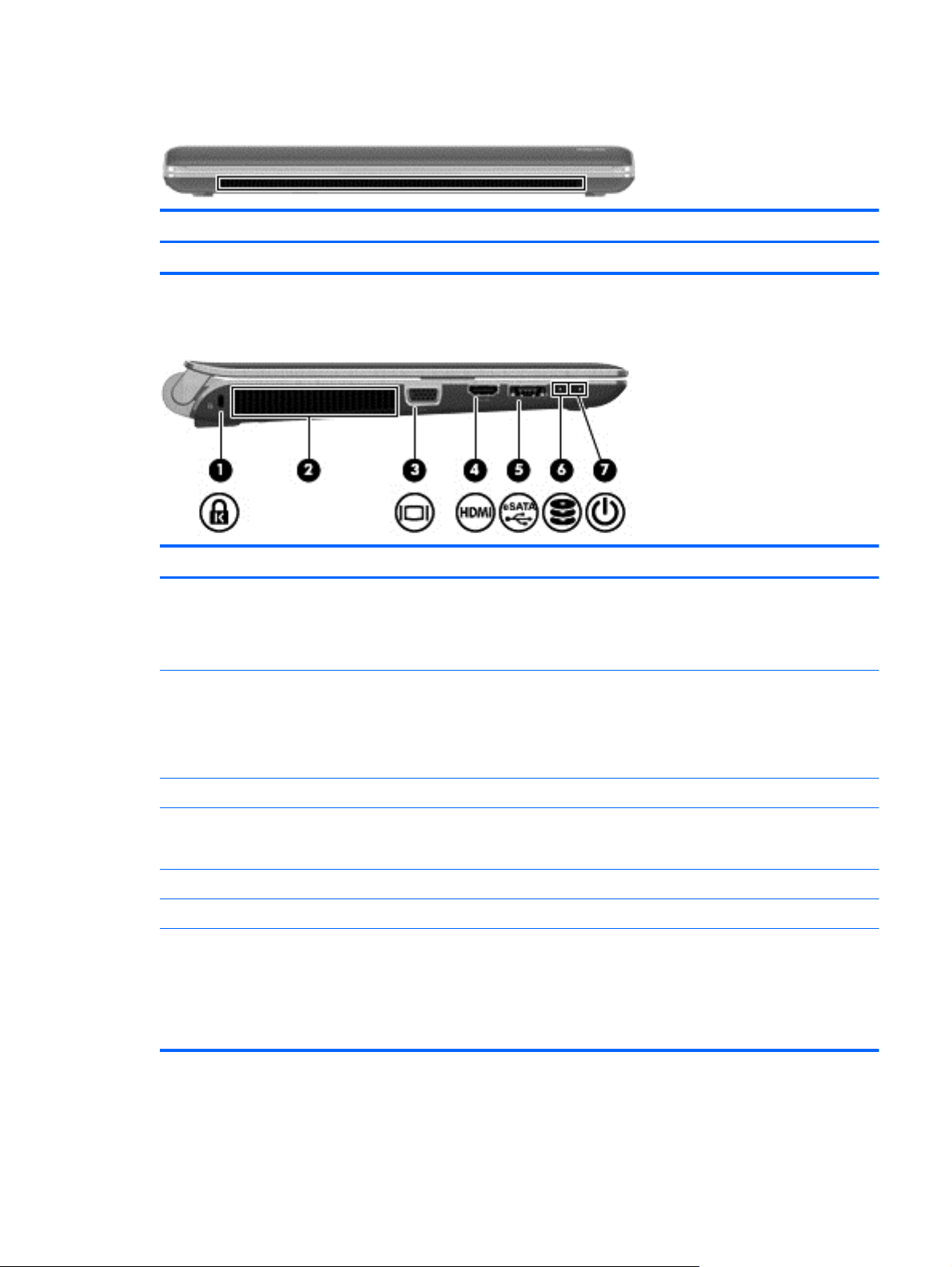
Left-side components ........................................................................................................................... 9
Right-side components ....................................................................................................................... 10
Bottom components ........................................................................................................................... 11
Wireless antennas .............................................................................................................................. 13
Additional hardware components ....................................................................................................... 14
3 Illustrated parts catalog ............................................................................................................................... 15
Serial number label ............................................................................................................................ 15
Computer major components ............................................................................................................. 16
Display assembly components ........................................................................................................... 19
Plastics kit .......................................................................................................................................... 21
Mass storage devices ......................................................................................................................... 22
Miscellaneous parts ............................................................................................................................ 23
Sequential part number listing ............................................................................................................ 23
4 Removal and replacement procedures ....................................................................................................... 27
Preliminary replacement requirements ............................................................................................... 27
Tools required .................................................................................................................... 27
Service considerations ....................................................................................................... 27
Plastic parts ....................................................................................................... 27
Cables and connectors ..................................................................................... 28
Drive handling ................................................................................................... 28
Grounding guidelines ......................................................................................................... 29
Electrostatic discharge damage ........................................................................ 29
v
Page 6

Packaging and transporting guidelines ............................................. 30
Workstation guidelines ..................................................................... 30
Equipment guidelines ....................................................................... 31
Component replacement procedures ................................................................................................. 32
Serial number label ............................................................................................................ 32
Computer feet .................................................................................................................... 33
Battery ............................................................................................................................... 34
SIM .................................................................................................................................... 35
Hard drive .......................................................................................................................... 36
Memory module ................................................................................................................. 39
RTC battery ....................................................................................................................... 41
Keyboard ........................................................................................................................... 42
Top cover ........................................................................................................................... 45
Speaker assembly ............................................................................................................. 48
Mini system board (left) ..................................................................................................... 50
Mini system board (right) ................................................................................................... 52
Power cable ....................................................................................................................... 54
WLAN module .................................................................................................................... 55
WWAN module .................................................................................................................. 57
Power button board ........................................................................................................... 59
Display assembly ............................................................................................................... 61
Fan/heat sink assembly ..................................................................................................... 67
System board ..................................................................................................................... 73
5 Setup Utility (BIOS) ....................................................................................................................................... 75
Starting Setup Utility ........................................................................................................................... 75
Using Setup Utility .............................................................................................................................. 76
Changing the language of Setup Utility ............................................................................. 76
Navigating and selecting in Setup Utility ............................................................................ 76
Display system information ................................................................................................ 77
Restoring default settings in Setup Utility .......................................................................... 77
Exiting Setup Utility ............................................................................................................ 78
Setup Utility menus ............................................................................................................................ 78
Main menu ......................................................................................................................... 78
Security menu .................................................................................................................... 78
System Configuration menu .............................................................................................. 79
Diagnostics menu .............................................................................................................. 79
Updating the BIOS ............................................................................................................................. 81
Determining the BIOS ........................................................................................................ 81
Downloading a BIOS update ............................................................................................. 81
6 Specifications ................................................................................................................................................ 83
Computer specifications ..................................................................................................................... 83
vi
Page 7

13.3-inch display specifications .......................................................................................................... 84
Hard drive specifications .................................................................................................................... 85
External Blu-ray ROM DVD±RW SuperMulti Double-Layer Drive specifications ............................... 86
External DVD±RW and CD-RW SuperMulti Double-Layer Combo Drive specifications .................... 87
7 Backup and recovery .................................................................................................................................... 88
Creating recovery discs ...................................................................................................................... 89
Backing up your information ............................................................................................................... 90
Using Windows Backup and Restore ................................................................................ 91
Using system restore points .............................................................................................. 91
When to create restore points ........................................................................... 91
Create a system restore point ........................................................................... 91
Restore to a previous date and time ................................................................. 92
Performing a recovery ........................................................................................................................ 92
Recovering from the recovery discs .................................................................................. 92
Recovering from the dedicated recovery partition (select models only) ............................ 93
8 Connector pin assignments ......................................................................................................................... 94
Audio-in (microphone) ........................................................................................................................ 94
Audio-out (headphone) ....................................................................................................................... 94
External monitor ................................................................................................................................. 94
HDMI .................................................................................................................................................. 96
RJ-45 (network) .................................................................................................................................. 97
Universal Serial Bus ........................................................................................................................... 97
9 Power cord set requirements ...................................................................................................................... 98
Requirements for all countries ............................................................................................................ 98
Requirements for specific countries and regions ............................................................................... 99
10 Recycling ................................................................................................................................................... 100
Battery .............................................................................................................................................. 100
Display .............................................................................................................................................. 100
Index ................................................................................................................................................................. 106
vii
Page 8

viii
Page 9

1 Product description
Category Description
Product Name HP Pavilion dm3 Entertainment PC
Processors Intel Pentium® U5400 (1.2 GHz, 3M L3 cache) UMA
Intel Pentium U5400 (1.2 GHz, 3M L3 cache) Discrete
Intel Core i3–330UM (1.2 GHz, 3M L3 cache) UMA
Intel Core i3–330UM (1.2 GHz, 3M L3 cache) Discrete
Intel Dual Core i5–430UM (1.2 GHz SC turbo up to 1.73GHz, 3M L3 cache)
Discrete
Intel Core i3–380UM (1.33 GHz, 3M L3 cache) UMA
Intel Core i3–380UM (1.33 GHz, 3M L3 cache) Discrete
Intel Core i5–470UM (1.33 GHz SC turbo, 3M L3 cache) Discrete
Chipset Intel HM55 Express Chipset
Graphics Intel HD Graphics
ATi Park LP (ATI Mobility Radeon™ HD5430) with 1024MB of dedicated video
memory (128Mx16 DDR3 800MHz x 4 PCs)
Support Blu-ray playback with HD Decode, DX10.1 and DX11 Support and HDMI
Support
Panels 33.8-cm (13.3-in) HD LED BrightView (1366x768) (3.6mm) SVA
Memory 2 customer-accessible/upgradable memory module slots
Supports up to 8 GB memory
Supports the following DDR3 configurations at 800 MHz:
8192-MB total system memory (4096 × 2)
●
6144-MB total system memory (2048 x 1 + 4096 x 1)
●
4096-MB total system memory (2048 × 2)
●
4096-MB total system memory (4096 x 1)
●
3072-MB total system memory (1024 x 1 + 2048 x 1)
●
2048-MB total system memory (1024 × 2)
●
2048-MB total system memory (2048 × 1)
●
1024-MB total system memory (1024 × 1)
●
1
Page 10

Category Description
Hard drives
640-GB, 7200-rpm
640-GB, 5400-rpm
500-GB, 7200-rpm
320-GB, 7200-rpm
250-GB, 7200-rpm
160-GB, 7200-rpm
Support for 128-GB SSD in single HDD configurations
Optical drives Supports only external optical drives
Supports 9.5-mm, 6.35-cm (2.5-inch) hard drives
●
Serial ATA (SATA)
●
HP ProtectSmart Hard Drive Protection Customer-accessible
●
12.7-mm tray load
●
Serial ATA (SATA)
●
External USB: DVD±RW SuperMulti Double-Layer Drive with LightScribe
●
External USB: Blu-ray ROM DVD±R/RW SuperMulti Double-Layer Drive with
●
LightScribe
Webcam Low-light VGA camera with fixed focus and microphone
Audio
Ethernet
Wireless Integrated wireless local-area network (WLAN) options via Half-Mini Card
Integrated WWAN and GPS function (FMC):
2 Altec/Lansing stereo speakers with enclosures
●
Headphone jack
●
Microphone jack
●
Integrated 10/100/1000 network interface card (NIC)
●
Ethernet cable not included
●
Broadcom 802.11 bgn WLAN + Bluetooth® Combo card
●
Broadcom 802.11 bgn WLAN card
●
Atheros 802.11 bgn WLAN card
●
Ralink 802.11 bgn WLAN + Bluetooth Combo card
●
Qualcomm Gobi2/Birlion with 2 antennas
●
5 band antenna support: 2100/1800/1900/800/900 with additional GPS band
●
x.x GHz antennas in display enclosure
●
2 Chapter 1 Product description
Page 11

Category Description
External media card Digital Media Slot, supporting the following optional digital card formats:
MultiMediaCard (MMC)
●
Secure Digital (SD) Memory Card
●
Secure Digital High Capacity (SDHC) Memory Card
●
Memory Stick (MS)
●
Memory Stick Pro (MSP)
●
xD-Picture Card (XD) (also types H and M)
●
SIM card slot:
Populated with WWAN
●
User accessible
●
Ports Audio-in (stereo microphone)
Audio-out (stereo headphone)
Hot Plug/Unplug and auto detector for correct output to wide-aspect vs. standard-
aspect video
HDMI v.1.3b supporting 1080p with HDCP key
Multi-pin AC power (non-smart pin)
RJ-45 (Ethernet, includes link and activity lights)
USB 2.0 (3)
VGA (Dsub 15-pin) supporting 1920 × 1200 external resolution at 75 GHz
Keyboard/pointing devices Full size keyboard
TouchPad with TouchPad buttons
Supports 2-way scroll with legend
Taps enabled by default
Touchpad on/off capability
Touchpad gesture to be default on; rotate gesture default off
Power requirements 65-W AC adapter (Non-smart ID Pin supported) with localized cable plug support
6-cell, 2.8-Ah (62-Wh) polymer battery
Security Security cable slot
Operating system Preinstalled:
Windows® 7 Basic (32-bit)
●
Windows 7 Basic (64-bit)
●
Windows 7 Premium (32-bit)
●
Windows 7 Premium (64-bit)
●
Windows 7 Professional (32-bit)
●
3
Page 12

Category Description
Microsoft® Office preinstalled on:
Serviceability End-user replaceable parts:
AC adapter
Battery (system)
Hard drive
Memory modules
RTC battery
SIM card (for WWAN)
Windows 7 Professional (64-bit)
●
Windows 7 Home Basic (32-bit and 64-bit)
●
Windows 7 Home Premium (32-bit and 64-bit)
●
Windows 7 Professional (32-bit and 64-bit)
●
4 Chapter 1 Product description
Page 13
2 External component identification
Top components
Display components
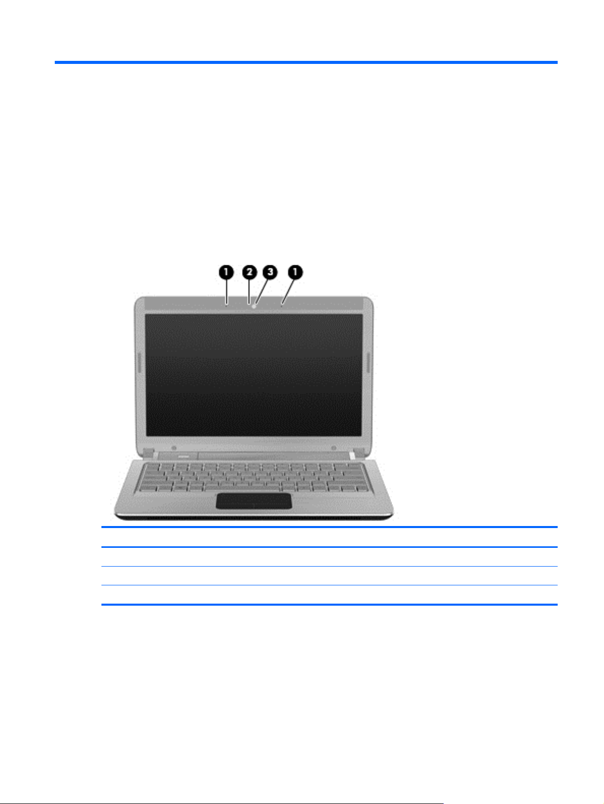
Item Component Function
(1) Internal microphones (2) Record sound.
(2) Webcam light On—The webcam is in use.
(3) Webcam Records video and captures still photographs.
Top components 5
Page 14
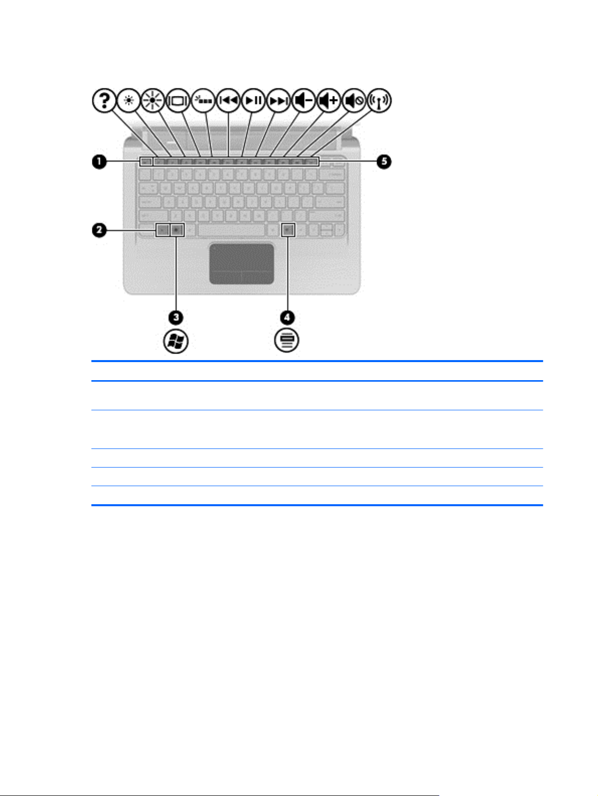
Keys
Item Component Function
(1) esc key Displays system information when pressed in
combination with the fn key.
(2) fn key Executes frequently used system functions when
pressed in combination with an arrow key or the esc
key.
(3) Windows logo key Displays the Windows Start menu.
(4) Windows applications key Displays a shortcut menu for items beneath the cursor.
(5) Action keys Executes frequently used system functions.
6 Chapter 2 External component identification
Page 15
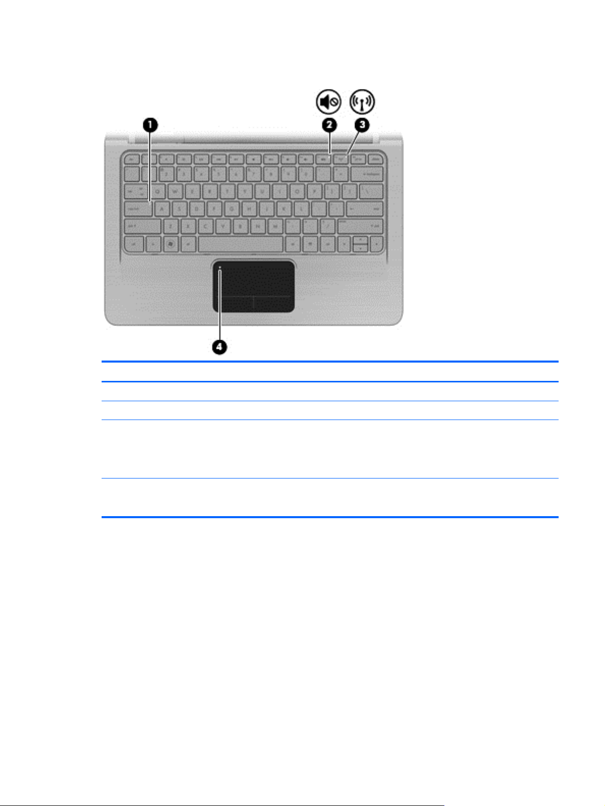
Lights
Item Component Description
(1) Caps lock light On—Caps lock is on.
(2) Mute light On—Computer sound is off.
(3) Wireless light
(4) TouchPad light
White—An integrated wireless device, such as a
●
wireless local area network (WLAN) device and/or
a Bluetooth® device, is on.
Amber—No wireless devices are detected.
●
Off—TouchPad is enabled.
●
Amber—TouchPad is disabled.
●
Top components 7
Page 16
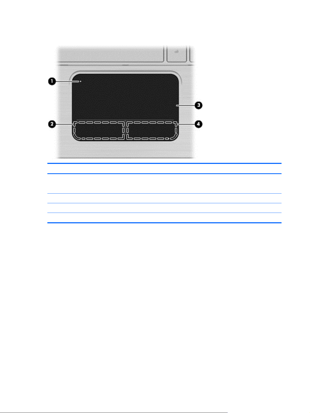
TouchPad components
Item Component Function
(1) TouchPad light
(2) Left TouchPad button Functions like the left button on an external mouse.
(3) TouchPad scroll zone Scrolls up or down.
(4) Right TouchPad button Functions like the right button on an external mouse.
Off—TouchPad is enabled.
●
Amber—TouchPad is disabled.
●
8 Chapter 2 External component identification
Page 17
Front components
Item Component Function
(1) Speakers (2) Produce sound.
Left-side components
Item Component Function
(1) Security cable slot Attaches an optional security cable to the computer.
NOTE: The security cable is designed to act as a
deterrent, but it might not prevent the computer from
being mishandled or stolen.
(2) Vent Enables airflow to cool internal components.
NOTE: The computer fan starts up automatically to
cool internal components and prevent overheating. It is
normal for the internal fan to cycle on and off during
routine operation.
(3) External monitor port Connects an external VGA monitor or projector.
(4) HDMI port Connects an optional video or audio device, such as a
high-definition television, or any compatible digital or
audio component.
(5) USB port Connects an optional USB device.
(6) Drive light On—The hard drive is in use.
(7) Power light Supports the following digital card formats:
On—The computer is on.
●
Flashing—The computer is in Sleep.
●
Off—The computer is off or in Hibernation.
●
Front components 9
Page 18
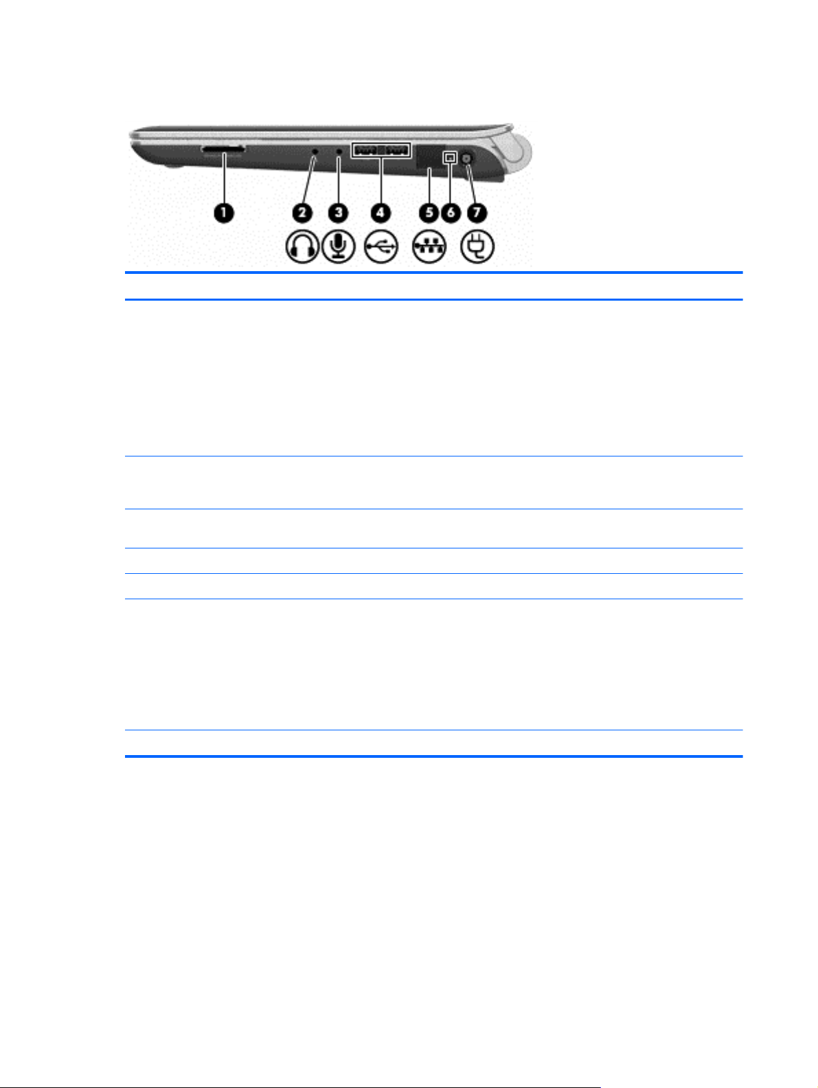
Right-side components
Item Component Function
(1) Digital Media Slot (select models only) Supports the following optional digital card formats:
(2) Audio-out (headphone) jack Produces sound when connected to optional powered
Memory Stick (MS)
●
Memory Stick Pro (MSP)
●
MultiMediaCard (MMC)
●
Secure Digital (SD) Memory Card
●
xD-Picture Card (XD)
●
stereo speakers, headphones, earbuds, a headset, or
television audio.
(3) Audio-in (microphone) jack Connects an optional computer headset microphone,
stereo array microphone, or monaural microphone.
(4) USB ports (2) Connects optional USB devices.
(5) RJ-45 (network) jack (optional) Connects a network cable.
(6) AC adapter light
(7) Power connector Connects an AC adapter.
Flashing white—The computer is in Sleep.
●
On white—The computer is connected to external
●
power.
Flashing amber—The computer is charged.
●
Off—The computer is not connected to external
●
power.
10 Chapter 2 External component identification
Page 19
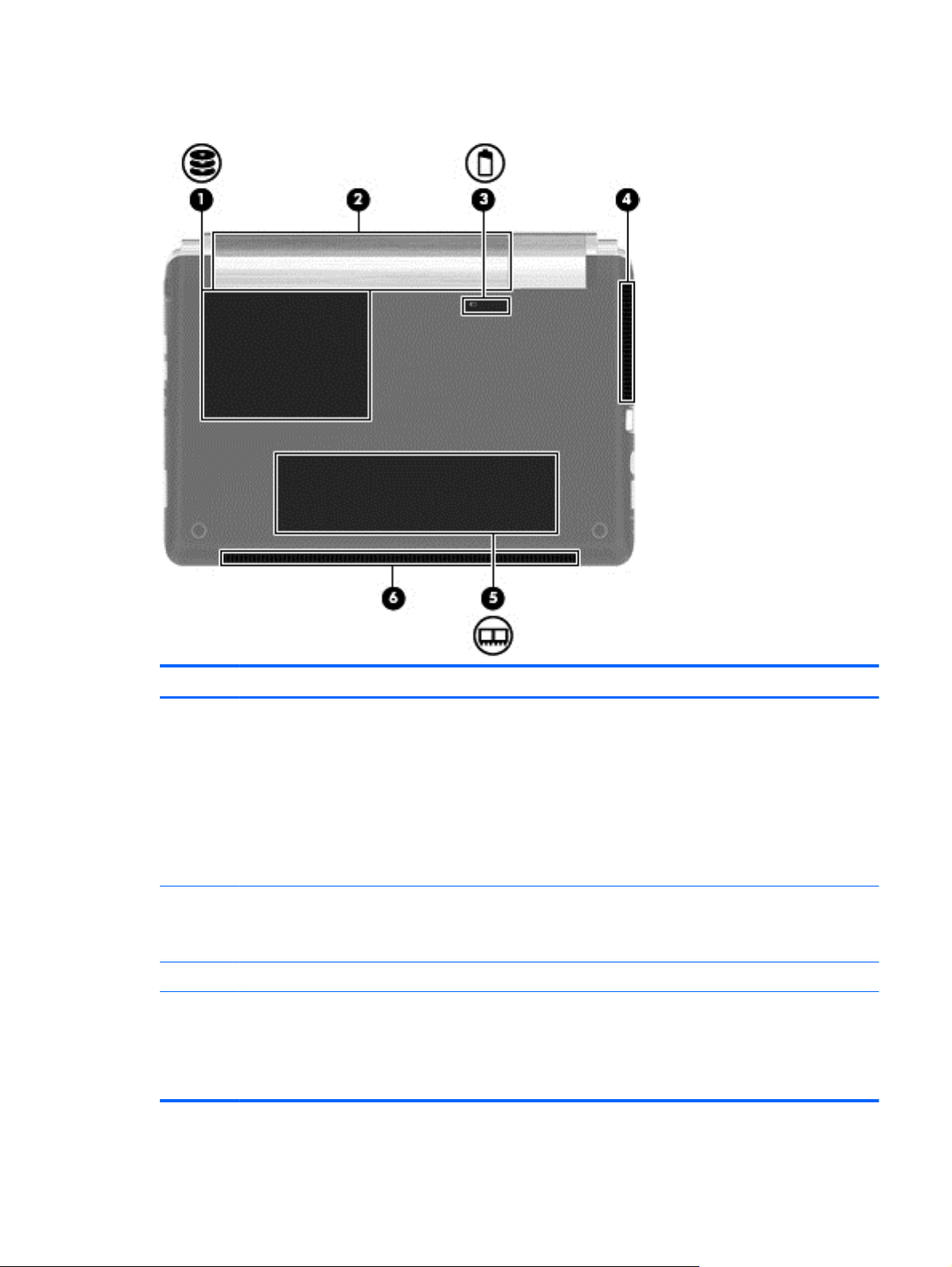
Bottom components
Item Component Function
(1) Hard drive bay Holds the hard drive and wireless wide area network
(WWAN) module (select models only).
NOTE: To prevent an unresponsive system, replace
the wireless module only with a wireless module
authorized for use in the computer by the
governmental agency that regulates wireless devices
in your country or region. If you replace the module
and then receive a warning message, remove the
module to restore computer functionality, and then
contact technical support through Help and Support.
(2) Battery bay Holds the battery and contains the SIM slot.
NOTE: The battery is preinstalled in the battery bay
at the factory.
(3) Battery release latch Releases the battery from the battery bay.
(4) Vent Enable airflow to cool internal components.
NOTE: The computer fan starts up automatically to
cool internal components and prevent overheating. It
is normal for the internal fan to cycle on and off during
routine operation.
Bottom components 11
Page 20

Item Component Function
(5) Memory module compartment Contains the memory module slot (2 slots on select
models) and a wireless LAN module.
NOTE: To prevent an unresponsive system, replace
the wireless module only with a wireless module
authorized for use in the computer by the
governmental agency that regulates wireless devices
in your country or region. If you replace the module
and then receive a warning message, remove the
module to restore computer functionality, and then
contact technical support through Help and Support.
(6) Speakers (2) Produce sounds.
12 Chapter 2 External component identification
Page 21
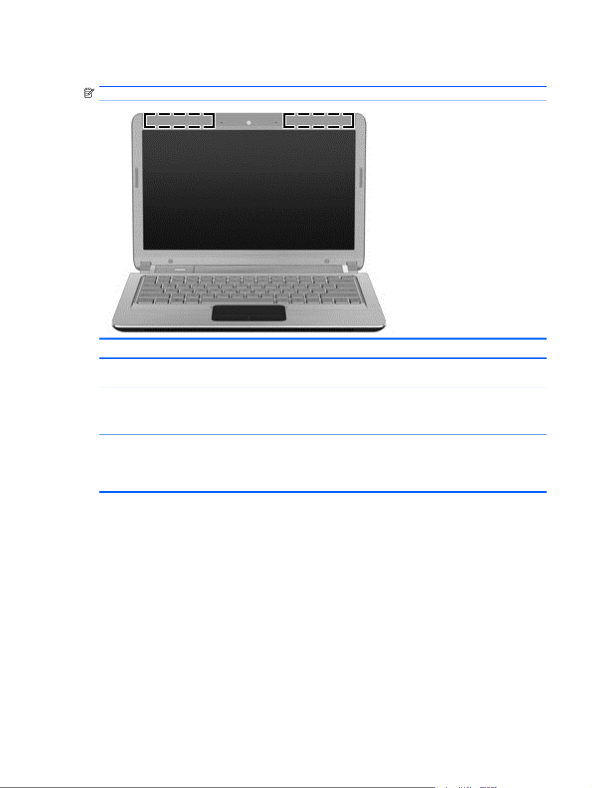
Wireless antennas
NOTE: Your computer might look different from the illustration in this section
Item Component Function
(1) WWAN antennas (2)*(select models only) Send and receive wireless signals to communicate
WLAN antennas (2)* Send and receive wireless signals to communicate
*The antennas are not visible from the outside of the device. For optimal transmission, keep the areas immediately around
the antennas free from obstructions.
To see wireless regulation notices, see the section of the Regulatory, Safety and Environmental Notices that applies to your
country or region. These notices are located in Help and Support.
with wireless wide-area networks (WWAN).
with wireless local area networks (WLAN).
Holds the battery and contains the SIM slot.
Wireless antennas 13
Page 22
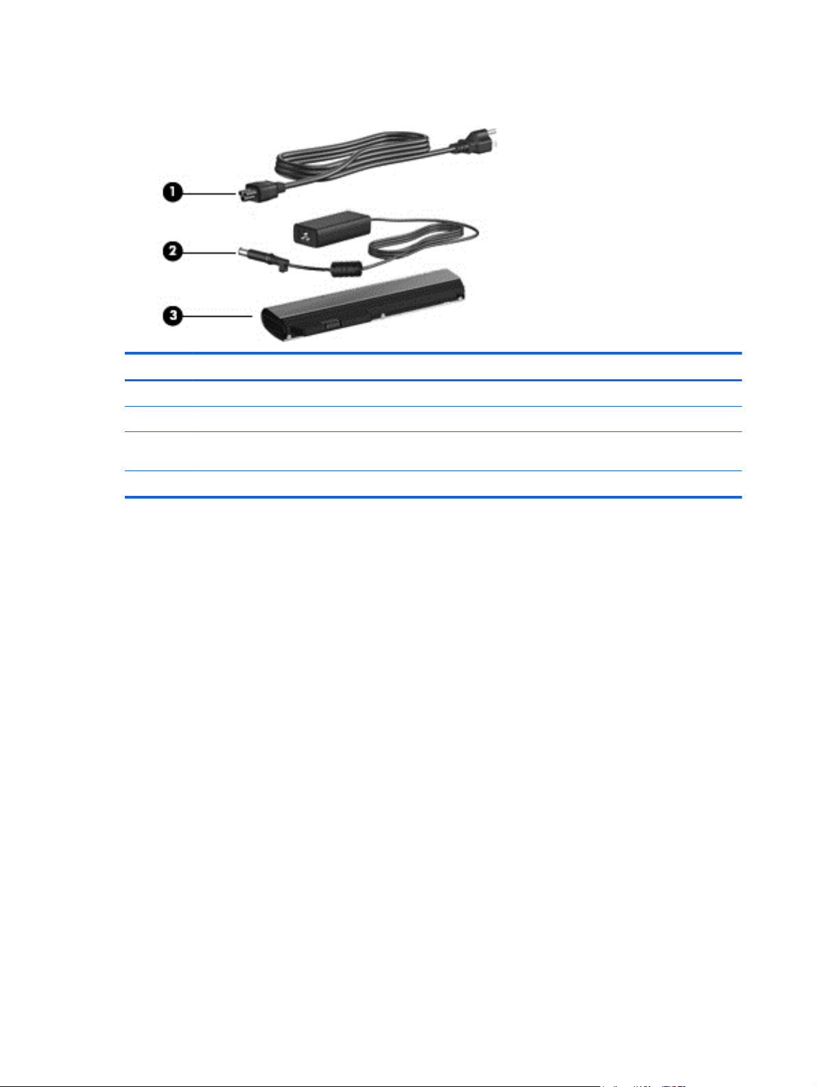
Additional hardware components
Item Component Function
(1) Power cord* Connects the AC adapter.
(2) AC adapter Converts AC power to DC power.
(3) Battery* Powers the computer when the computer is not
*Batteries and power cords vary in appearance by region or country.
plugged into external power.
14 Chapter 2 External component identification
Page 23
3 Illustrated parts catalog
Serial number label
When ordering parts or requesting information, provide the computer serial number and model
description provided on the serial number label.
(1) Product name—This is the product name affixed to the front of the computer.
(2) Serial number (s/n)—This is an alphanumeric identifier that is unique to each product.
(3) Part number/Product number (p/n)—This number provides specific information about the product's
hardware components. The part number helps a service technician to determine what components
and parts are needed.
(4) Warranty period—This number describes the duration of the warranty period for the computer.
Serial number label 15
Page 24
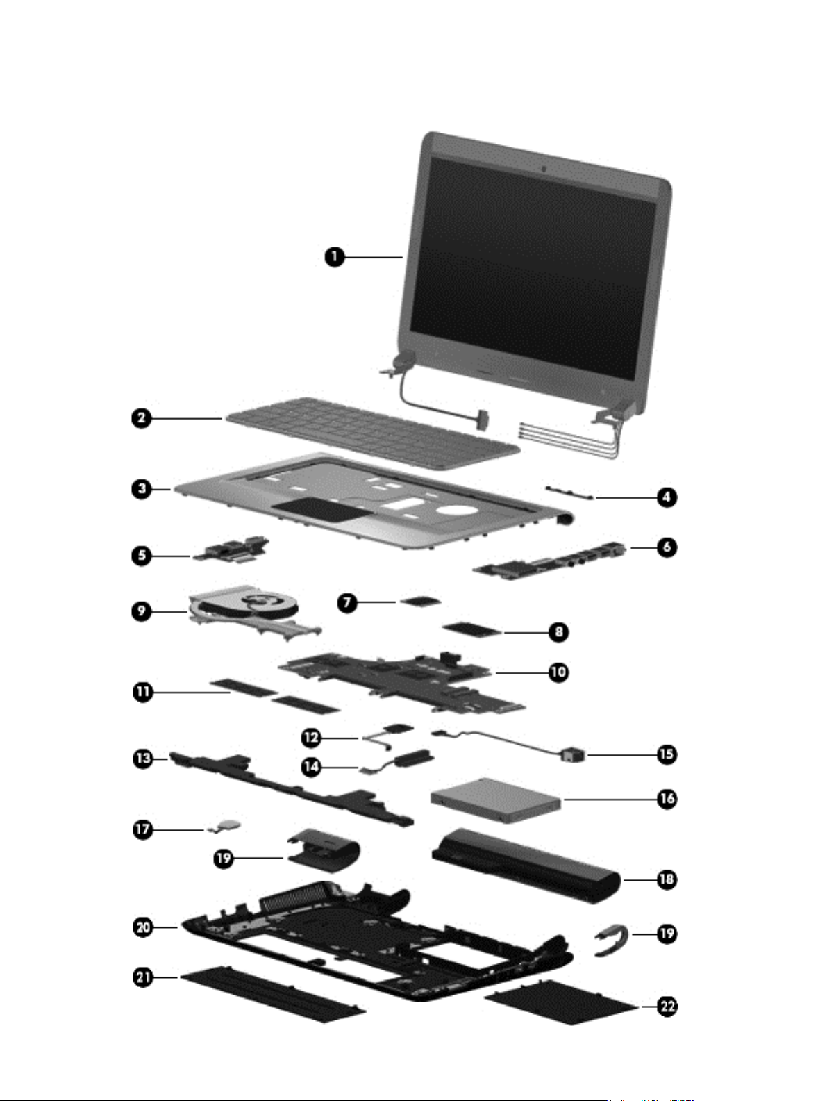
Computer major components
16 Chapter 3 Illustrated parts catalog
Page 25

Item Description Spare part number
(1) Display assembly
33.8-cm (13.3-in) HD LED Brightview SVA
NOTE: For more information on the display assembly internal component
spare part information, see
(2) Keyboard (includes keyboard cable) for use in the:
United States 619433-001
French Canada 619433-121
Thailand 619433-281
Japan 619433-291
Taiwan 619433-AB1
South Korea 619433-AD1
Backlit Keyboard (includes keyboard cable) for use in the:
United States 619434-001
French Canada 619434-121
Thailand 619434-281
Japan 619434-291
Taiwan 619434-AB1
South Korea 619434-AD1
Display assembly components on page 19.
633279–001
(3) Top cover (includes TouchPad) 626743-001
(4) Webcam module 619459–001
(5) Left mini system board 626740–001
(6) Right mini system board 626739–001
(7) WLAN module
Broadcom 802.11 bgn WLAN + Bluetooth Combo card 621184-001
Broadcom 802.11 bgn WLAN card 621751-001
Atheros 802.11 bgn WLAN card 621752-001
Ralink 802.11 bgn WLAN + Bluetooth Combo card 621753-001
(8) HSPA EV-DO Birlion MiniCard UNDP WWAN module (optional) 621185-001
(9) Heat sink (includes replacement thermal material)
UMA 619440-001
Discrete 626735-001
(10) System board (includes embedded processor and replacement thermal)
Intel Pentium U5400 (1.2 GHz, 3M L3 cache) UMA 619456-001
Intel Pentium U5400 (1.2 GHz, 3M L3 cache) Discrete 619457-001
Computer major components 17
Page 26

Item Description Spare part number
Intel Core i3–330UM (1.2 GHz, 3M L3 cache) UMA 621560-001
Intel Core i3–330UM (1.2 GHz, 3M L3 cache) Discrete 621561-001
Intel Dual Core i5–430UM (1.2 GHz SC turbo up to 1.73GHz, 3M L3 cache)
Discrete
Intel Core i3–380UM (1.33 GHz, 3M L3 cache) UMA 626598-001
Intel Core i3–380UM (1.33 GHz, 3M L3 cache) Discrete 626599-001
Intel Core i5–470UM (1.33 GHz SC turbo, 3M L3 cache) Discrete 626600-001
(11) Memory modules (PC3, 1066 MHz)
2GB 598856-001
1GB 598859-001
4GB 599092-001
(12) Power button board 626742–001
(13) Speakers 619454-001
(14) Hard drive cable (included in cable kit) 626734-001
(15) Power and RJ-45 connector and cable (included in cable kit)
(16) Hard drive (includes hard drive bracket and Mylar cover)
640 GB, 7200 RPM 619445-001
500 GB, 7200 RPM 619444-001
320 GB, 7200 RPM 619443-001
621562-001
250 GB, 7200 RPM 619442-001
160 GB, 7200 RPM 619441-001
640 GB,INTERNAL, 7200 RPM 621046-001
SSD 160 GB 619445-001
Hard Drive Hardware Kit (not illustrated; includes hard drive bracket and hard
drive screws)
(17) RTC battery (includes cable) 619451-001
(18) Battery 6C 62WHr 2.8Ah LI 619438-001
(19) Hinge covers 626737-001
(20) Base enclosure 619437-001
Plastics kit 619450-001
(21) Memory module compartment access cover
(22) Hard drive bay access cover
619446-001
18 Chapter 3 Illustrated parts catalog
Page 27
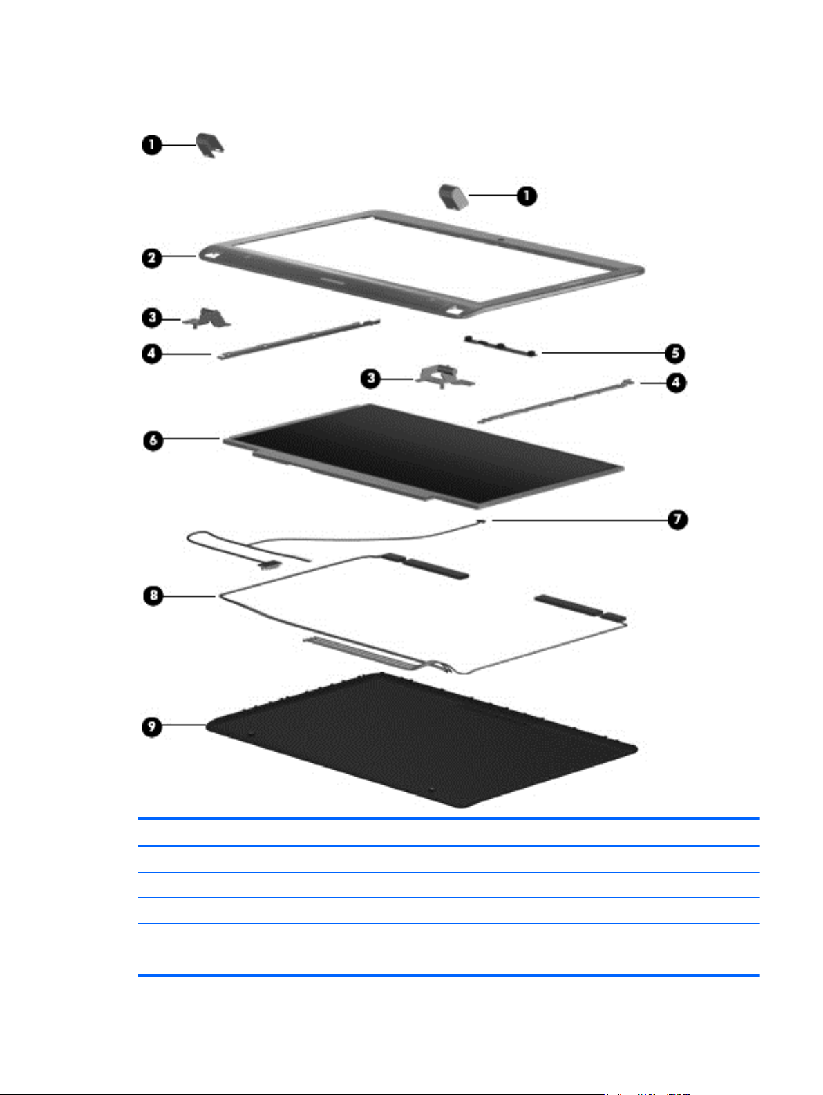
Display assembly components
Item Description Spare part number
(1) Display hinge covers 626637-001
(2) Display bezel (includes WLAN and WWAN antennas) 619499–001
(3) Display hinges (with hinges) 619477-001
(5) Webcam module 619549-001
(6) 33.8-cm (13.3-in) HD LED Brightview SVA panel 619448-001
Display assembly components 19
Page 28

Item Description Spare part number
(7) Display cable (includes microphone) 619439–001
(8) Wireless antenna (includes WLAN and WWAN antenna transceivers and cable) 619435-001
(9) Display back cover (includes logo) for use with: 619436–001
Display EMI shield (not illustrated) 626736-001
20 Chapter 3 Illustrated parts catalog
Page 29
Plastics kit
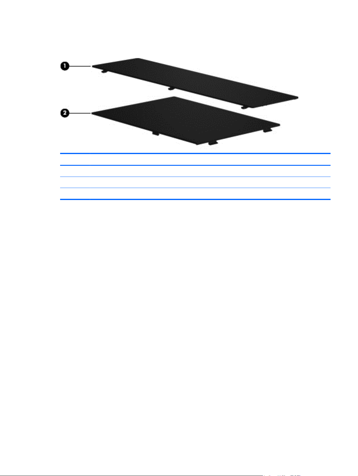
Item Description Spare part number
Plastics Kit 619450-001
(1) Memory module compartment cover
(2) Hard drive bay access cover
Plastics kit 21
Page 30
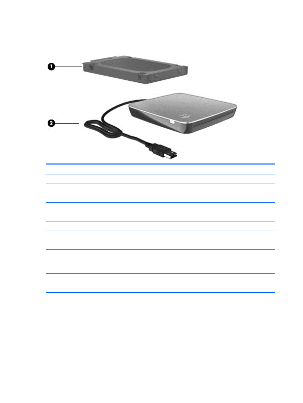
Mass storage devices
Item Description Spare part number
(1) Hard drive (includes hard drive bracket and Mylar cover)
640 GB, 7200 RPM 619445-001
500 GB, 7200 RPM 619444-001
320 GB, 7200 RPM 619443-001
250 GB, 7200 RPM 619442-001
160 GB, 7200 RPM 619441-001
640 GB,INTERNAL, 7200 RPM 621046-001
SSD 160 GB 619455-001
Hard Drive Hardware Kit (not illustrated; includes hard drive bracket and hard
drive screws)
(2) External Optical drive (optional)
DVD±RW and CD-RW SuperMulti Double-Layer Combo Drive with LightScribe 584383–001
Blu-ray ROM with LightScribe DVD±R/RW SuperMulti Double-Layer Drive 584384–001
619446-001
22 Chapter 3 Illustrated parts catalog
Page 31

Miscellaneous parts
Description Spare part number
AC adapter 609939-001
AC adapter (for use in emerging markets) 609948-001
Power cords for use in:
Australia 490371-011
India 490371-D61
Japan 490371-291
South Korea 490371-AD1
Taiwan 490371-AB1
Thailand 490371-201
the People’s Republic of China 490371-AA1
the United Kingdom and Singapore 490371-031
the United States 490371-001
Cable Kit
Power cable
●
hard drive cable
●
Rubber Kit 619452–001
Screw Kit
Phillips PM2.0×3.0 screw
●
Phillips PM2.5×4.0 screw
●
Phillips PM2.5×6.0 screw
●
Phillips PM2.5×12.0 screw
●
Phillips PM3.0×4.0 screw
●
Phillips PM1.6×2.5 screw
●
Phillips PM2.5×.5 screw
●
Sequential part number listing
Spare part
number
Description
626734–001
619453–001
490371-001 Power cord for use in North America
490371-011 Power cord for use in Australia
490371-031 Power cord for use in the United Kingdom and Singapore
490371-201 Power cord for use in Thailand
Miscellaneous parts 23
Page 32

Spare part
number
490371-291 Power cord for use in Japan
490371-AA1 Power cord for use in the People's Republic of China
490371-AB1 Power cord for use in Taiwan
490371-AD1 Power cord for use in South Korea
490371-D61 Power cord for use in India
584383-001 DVD±RW and CD-RW SuperMulti Double-Layer Combo Drive with LightScribe external drive (includes
584384-001 Blu-ray ROM DVD±RW SuperMulti Double-Layer Drive with LightScribe external drive (includes bezel,
598856-001 4096-MB memory module (PC3, 1066 MHz)
598859-001 2048-MB memory module (PC3, 1066 MHz)
599092-001 1024-MB memory module (PC3, 1066 MHz)
609939-001 65-W RC/V AC adapter
609948-001 65-W RC/V AC adapter (for use in emerging markets)
619433-001 Keyboard for use in the United States (includes cable and 2 retention clips)
619433-121 Keyboard for use in French Canada (includes cable and 2 retention clips)
Description
bezel, bracket, and cable)
bracket, and cable)
619433-281 Keyboard for use in Thailand (includes cable and 2 retention clips)
619433-291 Keyboard for use in Japan (includes cable and 2 retention clips)
619433-AB1 Keyboard for use in Taiwan (includes cable and 2 retention clips)
619433-AD1 Keyboard for use in South Korea (includes cable and 2 retention clips)
619434-001 Backlit keyboard for use in the United States (includes cable and 2 retention clips)
619434-121 Backlit keyboard for use in French Canada (includes cable and 2 retention clips)
619434-281 Backlit Keyboard for use in Thailand (includes cable and 2 retention clips)
619434-291 Backlit Keyboard for use in Japan (includes cable and 2 retention clips)
619434-AB1 Backlit keyboard for use in Taiwan (includes cable and 2 retention clips)
619434-AD1 Backlit keyboard for use in South Korea (includes cable and 2 retention clips)
619435-001 Antennas (includes WLAN and WWAN antennas)
619436-001 Display back cover
619437-001 Base enclosure
619438–001 6-cell, 62-WHr 2.8Ah LI battery
619439-001 Display cable
619440–001 Heat sink for use only with computer models equipped with UMA graphics subsystem (includes
replacement thermal material)
619441-001 160-GB, 7200-rpm hard drive (includes hard drive bracket and Mylar cover)
619442-001 250-GB, 7200-rpm hard drive (includes hard drive bracket and Mylar cover)
24 Chapter 3 Illustrated parts catalog
Page 33

Spare part
number
619443-001 320-GB, 7200-rpm hard drive (includes hard drive bracket and Mylar cover)
619444–001 500-GB, 7200-rpm hard drive (includes hard drive bracket and Mylar cover)
619445-001 640-GB, 7200-rpm hard drive (includes hard drive bracket and Mylar cover)
619446–001 Hard Drive Hardware Kit (includes hard drive bracket, Mylar cover, and hard drive screws)
619447–001 Display hinges (includes left and right display hinges)
619448–001 33.8-cm (13.3-in) HD LED BrightView display panel (includes display panel and backlight cables)
619449–001 Display assembly bezel (includes WLAN and WWAN antennas)
619450–001 Plastics Kit
Description
NOTE: For more Plastics Kit information, see
619451-001 RTC battery
619452-001 Rubber Kit
619453–001 Screw Kit
619454-001 Speakers
619455–001 128-GB, SSD
619456–001 System board equipped with UMA graphics subsystem and Intel Pentium U5400 (1.2 GHz, 3M L3 cache);
includes replacement thermal material)
619457–001 System board equipped with discrete graphics subsystem and Intel Pentium U5400 (1.2 GHz, 3M L3
cache); includes replacement thermal material)
619459-001 Webcam
621046-001 160-GB, 7200-rpm internal hard drive (includes hard drive bracket and Mylar cover)
621184-001 Broadcom 802.11 bgn WLAN + Bluetooth Combo card
621185–001 HSPA EV-DO Birlion MiniCard UNDP WWAN module
621560–001 System board equipped with UMA graphics subsystem and Intel Core i3–330UM (1.2 GHz, 3M L3
cache); includes replacement thermal material)
621561–001 System board equipped with discrete graphics subsystem and Intel Core i3–330UM (1.2 GHz, 3M L3
cache); includes replacement thermal material)
Plastics kit on page 21.
621562–001 System board equipped with discrete graphics subsystem andIntel Dual Core i5–430UM (1.2 GHz SC
turbo up to 1.73GHz, 3M L3 cache; includes replacement thermal material)
621751-001 Broadcom 802.11 bgn WLAN card
621752-001 Atheros 802.11 bgn WLAN card
621753-001 Ralink 802.11 bgn WLAN + Bluetooth Combo card
626598–001 System board equipped with UMA graphics subsystem and Intel Core i3–380UM (1.33 GHz, 3M L3
cache; includes replacement thermal material)
626599–001 System board equipped with discrete graphics subsystem and Intel Core i3–380UM (1.33 GHz, 3M L3
cache; includes replacement thermal material)
626600–001 System board equipped with discrete graphics subsystem and Intel Core i5–470UM (1.33 GHz SC turbo,
3M L3 cache; includes replacement thermal material)
Sequential part number listing 25
Page 34

Spare part
number
626734-001 Cable kit
626735–001 Heat sink for use only with computer models equipped with discrete graphics subsystem (includes
626736-001 Display EMI shield
626737-001 Display hinge covers
626739-001 Right mini system board
626740-001 Left mini system board
626742–001 Power button board
626743–001 Top cover (includes TouchPad and TouchPad cable)
633279–001 33.8-cm (13.3-in) HD LED BrightView display assembly
Description
replacement thermal material)
26 Chapter 3 Illustrated parts catalog
Page 35

4 Removal and replacement procedures
Preliminary replacement requirements
Tools required
Use the following tools to complete the removal and replacement procedures:
Magnetic screwdriver
●
Phillips P0 and P1 screwdrivers
●
Flat-bladed screwdriver
●
Service considerations
The following sections include some of the considerations that you should keep in mind during
disassembly and assembly procedures.
NOTE: As you remove each subassembly from the computer, place the subassembly (and all
accompanying screws) away from the work area to prevent damage.
Plastic parts
CAUTION: Using excessive force during disassembly and reassembly can damage plastic parts.
Use care when handling the plastic parts. Apply pressure only at the points designated in the
maintenance instructions.
Preliminary replacement requirements 27
Page 36

Cables and connectors
CAUTION: When servicing the computer, be sure that cables are placed in their proper locations
during the reassembly process. Improper cable placement can damage the computer.
Cables must be handled with extreme care to avoid damage. Apply only the tension required to
unseat or seat the cables during removal and insertion. Handle cables by the connector whenever
possible. In all cases, avoid bending, twisting, or tearing cables. Be sure that cables are routed in
such a way that they cannot be caught or snagged by parts being removed or replaced. Handle flex
cables with extreme care; these cables tear easily.
Drive handling
CAUTION: Drives are fragile components that must be handled with care. To prevent damage to
the computer, damage to a drive, or loss of information, observe these precautions:
Before removing or inserting a hard drive, shut down the computer. If you are unsure whether the
computer is off or in Hibernation, turn the computer on, and then shut it down through the
operating system.
Before handling a drive, be sure that you are discharged of static electricity. While handling a drive,
avoid touching the connector.
Before removing a diskette drive or optical drive, be sure that a diskette or disc is not in the drive and
be sure that the optical drive tray is closed.
Handle drives on surfaces covered with at least one inch of shock-proof foam.
Avoid dropping drives from any height onto any surface.
After removing a hard drive, an optical drive, or a diskette drive, place it in a static-proof bag.
Avoid exposing a hard drive to products that have magnetic fields, such as monitors or speakers.
Avoid exposing a drive to temperature extremes or liquids.
If a drive must be mailed, place the drive in a bubble pack mailer or other suitable form of protective
packaging and label the package “FRAGILE.”
28 Chapter 4 Removal and replacement procedures
Page 37

Grounding guidelines
Electrostatic discharge damage
Electronic components are sensitive to electrostatic discharge (ESD). Circuitry design and structure
determine the degree of sensitivity. Networks built into many integrated circuits provide some
protection, but in many cases, ESD contains enough power to alter device parameters or melt
silicon junctions.
A discharge of static electricity from a finger or other conductor can destroy static-sensitive devices or
microcircuitry. Even if the spark is neither felt nor heard, damage may have occurred.
An electronic device exposed to ESD may not be affected at all and can work perfectly throughout a
normal cycle. Or the device may function normally for a while, then degrade in the internal layers,
reducing its life expectancy.
CAUTION: To prevent damage to the computer when you are removing or installing internal
components, observe these precautions:
Keep components in their electrostatic-safe containers until you are ready to install them.
Use nonmagnetic tools.
Before touching an electronic component, discharge static electricity by using the guidelines
described in this section.
Avoid touching pins, leads, and circuitry. Handle electronic components as little as possible.
If you remove a component, place it in an electrostatic-safe container.
The following table shows how humidity affects the electrostatic voltage levels generated by
different activities.
CAUTION: A product can be degraded by as little as 700 V.
Typical electrostatic voltage levels
Relative humidity
Event 10% 40% 55%
Walking across carpet 35,000 V 15,000 V 7,500 V
Walking across vinyl floor 12,000 V 5,000 V 3,000 V
Motions of bench worker 6,000 v 800 V 400 V
Removing DIPS from plastic tube 2,000 V 700 V 400 V
Removing DIPS from vinyl tray 11,500 V 4,000 V 2,000 V
Removing DIPS from Styrofoam 14,500 V 5,000 V 3,500 V
Removing bubble pack from PCB 26,500 V 20,000 V 7,000 V
Packing PCBs in foam-lined box 21,000 V 11,000 V 5,000 V
Preliminary replacement requirements 29
Page 38

Packaging and transporting guidelines
Follow these grounding guidelines when packaging and transporting equipment:
To avoid hand contact, transport products in static-safe tubes, bags, or boxes.
●
Protect ESD-sensitive parts and assemblies with conductive or approved containers or
●
packaging.
Keep ESD-sensitive parts in their containers until the parts arrive at static-free workstations.
●
Place items on a grounded surface before removing items from their containers.
●
Always be properly grounded when touching a component or assembly.
●
Store reusable ESD-sensitive parts from assemblies in protective packaging or
●
nonconductive foam.
Use transporters and conveyors made of antistatic belts and roller bushings. Be sure that
●
mechanized equipment used for moving materials is wired to ground and that proper materials
are selected to avoid static charging. When grounding is not possible, use an ionizer to dissipate
electric charges.
Workstation guidelines
Follow these grounding workstation guidelines:
Cover the workstation with approved static-shielding material.
●
Use a wrist strap connected to a properly grounded work surface and use properly grounded
●
tools and equipment.
Use conductive field service tools, such as cutters, screwdrivers, and vacuums.
●
When fixtures must directly contact dissipative surfaces, use fixtures made only of static-
●
safe materials.
Keep the work area free of nonconductive materials, such as ordinary plastic assembly aids
●
and Styrofoam.
Handle ESD-sensitive components, parts, and assemblies by the case or PCM laminate. Handle
●
these items only at static-free workstations.
Avoid contact with pins, leads, or circuitry.
●
Turn off power and input signals before inserting or removing connectors or test equipment.
●
30 Chapter 4 Removal and replacement procedures
Page 39

Equipment guidelines
Grounding equipment must include either a wrist strap or a foot strap at a grounded workstation.
When seated, wear a wrist strap connected to a grounded system. Wrist straps are flexible
●
straps with a minimum of one megohm ±10% resistance in the ground cords. To provide proper
ground, wear a strap snugly against the skin at all times. On grounded mats with banana-plug
connectors, use alligator clips to connect a wrist strap.
When standing, use foot straps and a grounded floor mat. Foot straps (heel, toe, or boot straps)
●
can be used at standing workstations and are compatible with most types of shoes or boots. On
conductive floors or dissipative floor mats, use foot straps on both feet with a minimum of one
megohm resistance between the operator and ground. To be effective, the conductive strips
must be worn in contact with the skin.
The following grounding equipment is recommended to prevent electrostatic damage:
Antistatic tape
●
Antistatic smocks, aprons, and sleeve protectors
●
Conductive bins and other assembly or soldering aids
●
Nonconductive foam
●
Conductive tabletop workstations with ground cords of one megohm resistance
●
Static-dissipative tables or floor mats with hard ties to the ground
●
Field service kits
●
Static awareness labels
●
Material-handling packages
●
Nonconductive plastic bags, tubes, or boxes
●
Metal tote boxes
●
Electrostatic voltage levels and protective materials
●
The following table lists the shielding protection provided by antistatic bags and floor mats.
Material Use Voltage protection level
Antistatic plastic Bags 1,500 V
Carbon-loaded plastic Floor mats 7,500 V
Metallized laminate Floor mats 5,000 V
Preliminary replacement requirements 31
Page 40

Component replacement procedures
This chapter provides removal and replacement procedures.
There are as many as 56 screws, in 7 different sizes, that must be removed, replaced, or loosened
when servicing the computer. Make special note of each screw size and location during removal
and replacement.
Serial number label
When ordering parts or requesting information, provide the computer serial number and model
description provided on the serial number label.
(1) Product name: This is the product name affixed to the front of the computer.
(2) Serial number (s/n): This is an alphanumeric identifier that is unique to each product.
(3) Part number/Product number (p/n): This number provides specific information about the product's
hardware components. The part number helps a service technician to determine what components
and parts are needed.
(4) Warranty period: This number describes the duration of the warranty period for the computer.
32 Chapter 4 Removal and replacement procedures
Page 41

Computer feet
Description Spare part number
Rubber Kit 619452-001
The computer feet are adhesive-backed rubber pads. The feet attach to the base enclosure in the
locations illustrated below.
Component replacement procedures 33
Page 42

Battery
Description Spare part number
6 cell, 2.80 Ah, 62 Wh 619438-001
Before disassembling the computer:
1. Shut down the computer. If you are unsure whether the computer is off or in Hibernation, turn on
the computer, and then shut it down through the operating system.
2. Disconnect all external devices connected to the computer.
3. Disconnect the power from the computer by first disconnecting the power cord from the AC
outlet and then disconnecting the AC adapter from the computer.
Remove the battery:
1. Turn the computer upside down on a flat surface.
2. Slide the battery release latch (1) to release the battery.
3. Slide the battery out of the computer (2).
To insert the battery, insert the bottom edge of the battery into the battery bay until the battery is
seated. The battery release latch automatically locks the battery into place.
34 Chapter 4 Removal and replacement procedures
Page 43

SIM
NOTE: The SIM is provided by the end user as a security measure for the WWAN module. The SIM
should be removed, placed into a static-dissipative container, and then replaced when the computer
is reassembled.
Before removing the SIM:
1. Shut down the computer. If you are unsure whether the computer is off or in Hibernation, turn
the computer on, and then shut it down through the operating system.
2. Disconnect all external devices connected to the computer.
3. Disconnect the power from the computer by first disconnecting the power cord from the AC
outlet, and then disconnecting the AC adapter from the computer.
4. Remove the battery (see
Remove the SIM:
1. Press in on the SIM (1) to release it from the SIM slot.
2. Remove the SIM (2) from the computer.
Reverse this procedure to install the SIM.
Battery on page 34).
Component replacement procedures 35
Page 44

Hard drive
NOTE: The hard drive spare part kit includes a hard drive bracket and hard drive connector. The
hard drive bracket and hard drive connector, as well as the hard drive bracket screws, are also
available in the Hard Drive Hardware Kit.
Description Spare part number
640 GB, 7200 rpm 619445–001
500 GB, 7200 rpm 619444-001
320 GB, 7200 rpm 619443-001
250 GB, 7200 rpm 619442-001
160 GB, 7200 rpm 619441-001
640 GB, INTERNAL, 7200 rpm 621046–001
SSD 160GB 619455-001
Hard drive hardware kit (not illustrated, includes connector, bracket, and screws) 619446-001
Before removing the hard drive:
1. Shut down the computer. If you are unsure whether the computer is off or in Hibernation, turn on
the computer, and then shut it down through the operating system.
2. Disconnect all external devices connected to the computer.
3. Disconnect the power from the computer by first disconnecting the power cord from the AC
outlet and then disconnecting the AC adapter from the computer.
4. Remove the battery (see
Battery on page 34).
Remove the hard drive:
1. Position the computer with the back toward you.
2. Press the orange hard drive release latch that located in the battery bay (1) and secures the
hard drive cover to the computer.
36 Chapter 4 Removal and replacement procedures
Page 45

3. Lift the left side of the hard drive cover and remove the cover (2). The hard drive cover is
included in the plastics kit, spare part number 619450-001.
4. Remove the two Phillips PM2.5×4.0 screws (1) that secure the hard drive to the system board.
5. Use the mylar tab to lift the hard drive out of the computer at an angle (2).
6. Disconnect the hard drive cable from the hard drive (3).
7. Use the mylar tab on the hard drive bracket to lift the hard drive out (4) of the hard drive bay.
Component replacement procedures 37
Page 46

8. To replace the hard drive bracket, remove the four Phillips PM3.0×4.0 screws (1) that secure the
hard drive bracket to the hard drive
9. Grasp the two attached Mylar tabs and pull the bracket straight up to remove it from the hard
drive (2).
Reverse this procedure to install the hard drive.
38 Chapter 4 Removal and replacement procedures
Page 47

Memory module
Description Spare part number
1 GB, 1066 MHz DDR3 598859-001
2 GB, 1066 MHz DDR3 598856-001
4 GB, 1066 MHz DDR3 599092-001
Before removing the memory module:
1. Shut down the computer. If you are unsure whether the computer is off or in Hibernation, turn on
the computer, and then shut it down through the operating system.
2. Disconnect all external devices connected to the computer.
3. Disconnect the power from the computer by first disconnecting the power cord from the AC
outlet and then disconnecting the AC adapter from the computer.
4. Remove the battery (see
Battery on page 34).
Remove the memory module:
1. Turn the computer upside down with the front toward you.
2. Slide the orange memory module cover release latch that located in the battery bay (1) and
secures the memory module cover to the computer.
3. Lift the cover off the computer (2). The mini-card compartment cover is included in the plastics
kit, spare part number 619450-001.
NOTE: Small tabs hold the cover in place. Firmly pull up on the cover to release the tabs.
4. Spread the retaining tabs (1) on each side of the memory module slot to release the memory
module. (The edge of the module opposite the slot rises away from the computer.)
Component replacement procedures 39
Page 48

5. Remove the module (2) by pulling it away from the slot at an angle.
NOTE: Memory modules are designed with a notch (3) to prevent incorrect insertion into the
memory module slot.
Reverse this procedure to install a memory module.
40 Chapter 4 Removal and replacement procedures
Page 49

RTC battery
Description Spare part number
RTC battery 619451-001
Before removing the RTC battery:
1. Shut down the computer. If you are unsure whether the computer is off or in Hibernation, turn on
the computer, and then shut it down through the operating system.
2. Disconnect all external devices connected to the computer.
3. Disconnect the power from the computer by first disconnecting the power cord from the AC
outlet and then disconnecting the AC adapter from the computer.
4. Remove the battery (see
5. Remove the memory module cover (see
Battery on page 34).
Memory module on page 39).
Remove the RTC battery:
1. Unplug the RTC battery from the system board (1).
2. Lift the battery (2) out of the computer.
Reverse this procedure to install the RTC battery.
Component replacement procedures 41
Page 50

Keyboard
Description Spare part number
For use in French Canada 619433-121
For use in Japan 619433-291
For use in the South Korea 619433-AD1
For use in Taiwan 619433-AB1
For use in Thailand 619433-281
For use in the United States 619433-001
For use in French Canada with backlight 619434-121
For use in Japan with backlight 619434-291
For use in South Korea with backlight 619434-AD1
For use in Taiwan with backlight 619434-AB1
For use in Thailand with backlight 619434-281
For use in the United States with backlight 619434-001
Before removing the keyboard:
1. Shut down the computer. If you are unsure whether the computer is off or in Hibernation, turn on
the computer, and then shut it down through the operating system.
2. Disconnect all external devices connected to the computer.
3. Disconnect the power from the computer by first disconnecting the power cord from the AC
outlet and then disconnecting the AC adapter from the computer.
4. Remove the battery (see
5. Remove the hard drive (see
6. Remove the Memory Module compartment cover (see
Battery on page 34).
Hard drive on page 36).
Memory module on page 39).
Remove the keyboard:
1. Turn the computer upside down with the front toward you.
2. Remove the three Phillips PM2.5×5.0 screws that secure the keyboard to the computer.
42 Chapter 4 Removal and replacement procedures
Page 51

3. Turn the computer display-side up with the front toward you.
4. Open the computer as far as possible.
5. Release the tabs along the top (1) edge of the keyboard using a thin flat-bladed screwdriver.
6. Lift the top edge of the keyboard, and set the keyboard back towards the display (2).
7. Release the zero insertion force (ZIF) connector (1) to which the keyboard cable is attached and
disconnect the keyboard cable (2) from the system board.
8. Remove the keyboard.
Component replacement procedures 43
Page 52

Reverse this procedure to install the keyboard.
44 Chapter 4 Removal and replacement procedures
Page 53

Top cover
Description Spare part number
Top cover (includes TouchPad) 626743-001
Before removing the top cover:
1. Shut down the computer. If you are unsure whether the computer is off or in Hibernation, turn on
2. Disconnect all external devices connected to the computer.
3. Disconnect the power from the computer by first disconnecting the power cord from the AC
4. Remove the following components:
the computer, and then shut it down through the operating system.
outlet and then disconnecting AC adapter from the computer.
a. Battery (see
b. Hard drive (See
c. Memory module (see
d. Keyboard (see
Battery on page 34)
Hard drive on page 36)
Memory module on page 39)
Keyboard on page 42)
Remove the top cover:
1. Turn the computer upside down with the front toward you.
2. Remove two rubber feet (1) and two rubber rectangles (2) that are located on the bottom of the
computer.
3. Remove the two Phillips PM2.5x3 and three Phillips PM2.5x6.5 screws on the base enclosure
(3). Remove the two silver trim rings (4) from the base enclosure.
4. Turn the computer display-side up with the front toward you.
5. Open the computer as far as possible.
Component replacement procedures 45
Page 54

6. Remove the three Phillips PM2.5×6.0 screw that secures the top cover to the computer.
7. Release the touchpad ZIF connector (1).
46 Chapter 4 Removal and replacement procedures
Page 55

8. Lift the rear edge of the top cover (1) until the top cover disengages from the base enclosure.
Remove the top cover (2).
NOTE: The TouchPad is glued to the top cover and is included with the top cover spare part.
Reverse this procedure to install the top cover.
Component replacement procedures 47
Page 56

Speaker assembly
Description Spare part number
Speaker assembly (includes cable) 619454-001
Before removing the speaker assembly:
1. Shut down the computer. If you are unsure whether the computer is off or in Hibernation, turn on
the computer, and then shut it down through the operating system.
2. Disconnect all external devices connected to the computer.
3. Disconnect the power from the computer by first disconnecting the power cord from the AC
outlet and then disconnecting the AC adapter from the computer.
4. Remove the following components:
a. Battery (see
b. Hard drive (see
c. Keyboard (see
d. Top cover (see
Battery on page 34)
Hard drive on page 36)
Keyboard on page 42)
Top cover on page 45)
Remove the speaker assembly:
1. Position the base enclosure with the front edge towards you.
2. Disconnect the speaker cable (1)
from the system board.
3. Remove the two Phillips PM2.5×3.0 screws (2) that secure the speaker assembly to the top
cover.
4. Lift up and remove the speakers (3).
48 Chapter 4 Removal and replacement procedures
Page 57

Reverse this procedure to install the speaker assembly.
Component replacement procedures 49
Page 58

Mini system board (left)
Description Spare part number
Mini system board (left) 626740-001
Before removing the mini system board:
1. Shut down the computer. If you are unsure whether the computer is off or in Hibernation, turn
the computer on, and then shut it down through the operating system.
2. Disconnect all external devices connected to the computer.
3. Disconnect the power from the computer by first disconnecting the power cord from the AC
outlet and then disconnecting the AC adapter from the computer.
4. Remove the following components:
a. Battery (see
b. Hard drive (see
c. Keyboard (see
d. Top cover (see
Battery on page 34)
Hard drive on page 36)
Keyboard on page 42)
Top cover on page 45)
Remove the mini system board (left):
1. Position the base enclosure with the front edge towards you.
2. Locate the ZIF connector (1) and disconnect it from the system board (2).
3. Remove the two Phillips PM2.0×3.0 screws (3) that secure the mini system board to the base
enclosure cover.
50 Chapter 4 Removal and replacement procedures
Page 59

4. Lift up and remove the mini system board (4).
Reverse this procedure to install the mini system board (left).
Component replacement procedures 51
Page 60

Mini system board (right)
Description Spare part number
Mini system board (right) 626739-001
Before removing the mini system board:
1. Shut down the computer. If you are unsure whether the computer is off or in Hibernation, turn
the computer on, and then shut it down through the operating system.
2. Disconnect all external devices connected to the computer.
3. Disconnect the power from the computer by first disconnecting the power cord from the AC
outlet and then disconnecting the AC adapter from the computer.
4. Remove the following components:
a. Battery (see
b. Hard drive (see
c. Keyboard (see
d. Top cover (see
Battery on page 34)
Hard drive on page 36)
Keyboard on page 42)
Top cover on page 45)
Remove the mini system board (right):
1. Position the base enclosure with the front edge towards you.
2. Locate the ZIF connector (1) and disconnect it from the system board (2).
3. Remove the three Phillips PM2.0×3.0 screws (3) that secure the mini system board to the base
enclosure cover.
52 Chapter 4 Removal and replacement procedures
Page 61

4. Lift up and remove the mini system board (4).
Reverse this procedure to install the mini system board (right).
Component replacement procedures 53
Page 62

Power cable
Description Spare part number
The power cable is included in the Cable Kit 626734-001
Before removing the power cable:
1. Shut down the computer. If you are unsure whether the computer is off or in Hibernation, turn
the computer on, and then shut it down through the operating system.
2. Disconnect all external devices connected to the computer.
3. Disconnect the power from the computer by first disconnecting the power cord from the AC
outlet and then disconnecting the AC adapter from the computer.
4. Remove the following components:
a. Battery (see
b. Hard drive (see
c. Keyboard (see
d. Top cover (see
Battery on page 34)
Hard drive on page 36)
Keyboard on page 42)
Top cover on page 45)
Remove the power cable:
1. Position the base enclosure with the front edge towards you.
2. Lift up on the power cable (1) and disconnect the cable from its routing (2) to remove the power
cable.
Reverse this procedure to install the power cable.
54 Chapter 4 Removal and replacement procedures
Page 63

WLAN module
Description Spare part
Broadcom 802.11 bgn WLAN + Bluetooth Combo card 621184-001
Broadcom 802.11 bgn WLAN card 621751-001
Atheros 802.11 bgn WLAN card 621752-001
Ralink 802.11 bgn WLAN + Bluetooth Combo card 621753-001
number
Before removing the WLAN module:
1. Shut down the computer. If you are unsure whether the computer is off or in Hibernation, turn on
the computer, and then shut it down through the operating system.
2. Disconnect all external devices connected to the computer.
3. Disconnect the power from the computer by first disconnecting the power cord from the AC
outlet and then disconnecting the AC adapter from the computer.
4. Remove the following components:
a. Battery (see
b. Hard drive (see
Battery on page 34)
Hard drive on page 36)
c. Keyboard (see
d. Top cover (see
Keyboard on page 42)
Top cover on page 45)
Remove the WLAN module:
1. Position the base enclosure with the front edge towards you.
2. Disconnect the main antenna cable and the auxiliary antenna cable (1) from the wireless
module.
3. Remove the two Phillips PM2.0×3.0 screws (2) that secures the WLAN module to the computer.
(The edge of the module opposite the slot rises away from the computer.)
Component replacement procedures 55
Page 64

4. Remove the WLAN module (3) by pulling it away from the slot at an angle.
CAUTION: To prevent an unresponsive system, replace the wireless module only with a
wireless module authorized for use in the computer by the governmental agency that regulates
wireless devices in your country or region. If you replace the module and then receive a warning
message, remove the module to restore computer functionality, and then contact technical
support through Help and Support.
NOTE: WLAN modules are designed with a notch (4) to prevent incorrect insertion into the
WLAN module slot.
Reverse this procedure to install a WLAN module.
56 Chapter 4 Removal and replacement procedures
Page 65

WWAN module
Description Spare part number
HSPA EV-DO Birlion MiniCard UNDP WWAN module (optional) 621185-001
Before removing the WWAN module:
1. Shut down the computer. If you are unsure whether the computer is off or in Hibernation, turn on
the computer, and then shut it down through the operating system.
2. Disconnect all external devices connected to the computer.
3. Disconnect the power from the computer by first disconnecting the power cord from the AC
outlet and then disconnecting the AC adapter from the computer.
4. Remove the following components:
a. Battery (see
b. Hard drive (see
c. Keyboard (see
d. Top cover (see
Battery on page 34)
Hard drive on page 36)
Keyboard on page 42)
Top cover on page 45)
Remove the WWAN module:
1. Position the base enclosure with the front edge towards you.
2. Disconnect the WWAN antenna cables (1) from the WWAN module.
NOTE: The red WWAN antenna cable is connected to the WWAN module “Main” terminal. The
blue WWAN antenna cable is connected to the WWAN module “Aux” terminal.
3. Remove the two Phillips PM2.0×3.0 screws (2) that secures the WWAN module to the computer.
(The edge of the module opposite the slot rises away from the computer.)
Component replacement procedures 57
Page 66

4. Remove the WWAN module (3) by pulling it away from the slot at an angle.
CAUTION: To prevent an unresponsive system, replace the wireless module only with a
wireless module authorized for use in the computer by the governmental agency that regulates
wireless devices in your country or region. If you replace the module and then receive a warning
message, remove the module to restore computer functionality, and then contact technical
support through Help and Support.
NOTE: WWAN modules are designed with a notch (4) to prevent incorrect insertion into the
WWAN module slot.
Reverse this procedure to install a WWAN module.
58 Chapter 4 Removal and replacement procedures
Page 67

Power button board
Description Spare part number
Power button board 626742-001
Before removing the power button board:
1. Shut down the computer. If you are unsure whether the computer is off or in Hibernation, turn
the computer on, and then shut it down through the operating system.
2. Disconnect all external devices connected to the computer.
3. Disconnect the power from the computer by first disconnecting the power cord from the AC
outlet and then disconnecting the AC adapter from the computer.
4. Remove the following components:
a. Battery (see
b. Hard drive (see
c. Keyboard (see
d. Top cover (see
Battery on page 34)
Hard drive on page 36)
Keyboard on page 42)
Top cover on page 45)
Remove the power button board:
1. Position the base enclosure with the front edge towards you.
2. Locate the power button board cable (1) and disconnect the cable from the system board (2).
3. Remove the Phillips PM2.0×3.0 screw (3) that secures the power button board to the system
board.
Component replacement procedures 59
Page 68

4. Lift out and remove the power button board (4).
Reverse this procedure to install the power button board.
60 Chapter 4 Removal and replacement procedures
Page 69

Display assembly
Description Spare part number
33.8-cm (13.3-in) HD LED BrightView display assembly 633279–001
Before removing the display assembly:
1. Shut down the computer. If you are unsure whether the computer is off or in Hibernation, turn on
the computer, and then shut it down through the operating system.
2. Disconnect all external devices connected to the computer.
3. Disconnect the power from the computer by first disconnecting the power cord from the AC
outlet and then disconnecting the AC adapter from the computer.
4. Remove the following components:
a. Battery (see
b. Keyboard (see
c. Top cover (see
5. Disconnect the wireless antenna cables from the WLAN module (see
Battery on page 34)
Keyboard on page 42)
Top cover on page 45)
WLAN module
on page 55).
6. Disconnect the wireless antenna cables from the WWAN module (see
WWAN module
on page 57).
Remove the display assembly:
1. Turn the computer display-side up, with the front toward you.
2. Open the display as far as possible.
3. Disconnect the display panel cable (1) from the system board and remove it from its routing
channel.
Component replacement procedures 61
Page 70

4. Pull the WLAN and WWAN antenna cables (2) from the clip in the routing channel leading to the
display hinge (3).
CAUTION: Support the display assembly when removing the display screws in the following
steps. Failure to support the display assembly can result in damage to the assembly and other
components.
5. Remove the three Phillips PM2.5×7.0 screws (1) that secure the display assembly to the
computer.
6. Remove the hinge covers (2)
62 Chapter 4 Removal and replacement procedures
Page 71

7. Lift the display panel (3) straight up to remove it.
Reverse this procedure to install the display assembly.
Component replacement procedures 63
Page 72

8. To replace any of the display assembly internal components, remove the following screw covers
and screws:
(1) Two rectangle mylar screw covers on the display bezel bottom edge
(2) Two round mylar screw covers on the display bezel bottom edge
(3) Two Phillips PM2.5×4.0 screws
The display screw covers are included in the rubber kit, spare part number 619452-001.
9. Lift up and remove the display back cover. The back cover is available using spare part number
619436-001.
Reverse this procedure to install the display back cover.
10. To replace the display panel, remove the two Phillips 2.5x3.0 screws from each hinge (1) and lift
up to remove each display panel hinge (2).
64 Chapter 4 Removal and replacement procedures
Page 73

11. Lift up and remove the display panel (3). The display panel is available using spare part number
619448-001.
12. To replace the webcam module (select models only), remove the two Phillips 2.0×3.0 (1) screws.
13. Disconnect the webcam module cable (2) from the webcam module, and remove the webcam
module (3). The webcam module is available using spare part number 619459-001.
Reverse this procedure to install the webcam module.
14. To replace the wireless antenna transceivers, lift up on the silver transceiver (1) and release the
adhesive material from the display cover (2).
Component replacement procedures 65
Page 74

15. Lift up to remove the antenna transceivers (3). The wireless antenna transceivers with cable is
available using spare part number 619435-001..
Reverse this procedure to install the display wireless antenna transceivers.
16. To replace the WWAN antenna transceivers, lift up on the silver transceiver and release the
adhesive material from the display cover (1).
17. Lift up to remove the antenna transceivers (2). The wireless antenna transceivers with cable is
available using spare part number 619435-001..
Reverse this procedure to install the display WWAN antenna transceivers.
66 Chapter 4 Removal and replacement procedures
Page 75

Fan/heat sink assembly
Description Spare part number
Fan/heat sink assembly (includes replacement thermal material) for use only with computer
models with UMA graphics subsystem memory
Fan/heat sink assembly (includes replacement thermal material) for use only with computer
models with discrete graphics subsystem memory
619440-001
626735-001
Before removing the fan/heat sink assembly:
1. Shut down the computer. If you are unsure whether the computer is off or in Hibernation, turn on
the computer, and then shut it down through the operating system.
2. Disconnect all external devices connected to the computer.
3. Disconnect the power from the computer by first disconnecting the power cord from the AC
outlet and then disconnecting the AC adapter from the computer.
4. Remove the following components:
a. Battery (see
b. Hard drive (see
c. Keyboard (see
d. Top cover (see
Battery on page 34)
Hard drive on page 36)
Keyboard on page 42)
Top cover on page 45)
e. Display assembly (see
f. System board (see
Display assembly on page 61)
System board on page 73)
Remove the fan/heat assembly (fan/heat sink appearance may vary):
NOTE: The following steps apply only to computer models equipped with graphics subsystems
having UMA memory.
1. Turn the system board right-side up, with the front toward you.
Component replacement procedures 67
Page 76

2. Disconnect the fan cable from the system board.
3. Follow the sequence embossed on heat sink to loosen the four Phillips PM2.5×7.0 captive
screws (1–4) that secure the fan/heat sink assembly to the system board.
NOTE: Due to the adhesive quality of the thermal material located between the fan/heat sink
assembly and system board components, it might be necessary to move the fan/heat sink
assembly from side to side to detach the assembly.
68 Chapter 4 Removal and replacement procedures
Page 77

4. Remove the fan/heat sink assembly (5) by lifting straight up.
NOTE: The following steps apply only to computer models equipped with graphics subsystems
having discrete memory.
1. Turn the system board right-side up, with the front toward you.
Component replacement procedures 69
Page 78

2. Disconnect the fan cable from the system board.
3. Loosen the four Phillips captive screws (1–4) and two Phillips spring-loaded captive screws (5–
6) that secure the fan/heat sink assembly.
NOTE: Due to the adhesive quality of the thermal material located between the fan/heat sink
assembly and system board components, it might be necessary to move the fan/heat sink
assembly from side to side to detach the assembly.
70 Chapter 4 Removal and replacement procedures
Page 79

4. Remove the fan/heat sink assembly (7) by lifting straight up.
Reverse this procedure to install the fan/heat sink assembly.
The thermal material must be thoroughly cleaned from the surface of the fan/heat sink assembly (1),
(3) and the processor (2) and video components (4) each time the fan/heat sink assembly is
removed. Thermal pads and thermal paste must be installed on all surfaces before the fan/heat sink
assembly is reinstalled.
NOTE: Thermal pads and thermal paste are included with all fan/heat sink assembly, system board,
and processor spare part kits.
The following illustration shows the locations for thermal material on systems with UMA graphics
subsystems.
The thermal material must be thoroughly cleaned from the surface of the fan/heat sink assembly (1)
and (3), and the processor component (2), each time the fan/heat sink assembly is removed. Thermal
Component replacement procedures 71
Page 80

pads and thermal paste must be installed on all surfaces before the fan/heat sink assembly is
reinstalled.
The following illustration shows the locations for thermal material on systems with discrete graphics
subsystems.
72 Chapter 4 Removal and replacement procedures
Page 81

System board
NOTE: The system board spare part kit includes UMA or discrete graphics subsystem memory and
replacement thermal material.
Description Spare part number
Intel Pentium U5400 (1.2 GHz, 3M L3 cache) UMA 619456-001
Intel Pentium U5400 (1.2 GHz, 3M L3 cache) Discrete 619457-001
Intel Core i3–330UM (1.2 GHz, 3M L3 cache) UMA 621560-001
Intel Core i3–330UM (1.2 GHz, 3M L3 cache) Discrete 621561-001
Intel Dual Core i5–430UM (1.2 GHz SC turbo up to 1.73GHz, 3M L3 cache) Discrete 621562-001
Intel Core i3–380UM (1.33 GHz, 3M L3 cache) UMA 626598-001
Intel Core i3–380UM (1.33 GHz, 3M L3 cache) Discrete 626599-001
Intel Core i5–470UM (1.33 GHz SC turbo, 3M L3 cache) Discrete 626600-001
When replacing the system board, be sure that the following components are removed from the
defective system board and installed on the replacement system board:
Memory modules (see
●
WLAN module (see
●
Memory module on page 39)
WLAN module on page 55)
Before removing the system board:
1. Shut down the computer. If you are unsure whether the computer is off or in Hibernation, turn on
the computer, and then shut it down through the operating system.
2. Disconnect all external devices connected to the computer.
3. Disconnect the power from the computer by first disconnecting the power cord from the AC
outlet and then disconnecting the AC adapter from the computer.
4. Remove the following components:
a. Battery (see
b. Hard drive (see
c. WLAN module (see
d. Memory module (see
e. Keyboard (see
f. Top cover (see
Battery on page 34)
Hard drive on page 36)
WLAN module on page 55)
Memory module on page 39)
Keyboard on page 42)
Top cover on page 45)
g. Display assembly (see
Display assembly on page 61)
Remove the following cables from the system board:
Power connector cable (see
●
Power cable on page 54).
Component replacement procedures 73
Page 82

Remove the system board:
1. Turn the computer upright with the right side toward you.
2. Remove the five Phillips PM2.5×4.0 (1) screws that secure the system board to the computer.
3. Lift the system board (2), and pull it away from the base enclosure.
4. Remove the hard drive cable (3) from the bottom of the system board.
Reverse this procedure to install the system board.
When replacing the system board, be sure that the following components are removed from the
defective system board and installed on the replacement system board:
Fan/heat sink assembly (see
●
Fan/heat sink assembly on page 67).
Reverse the preceding procedure to install the system board.
74 Chapter 4 Removal and replacement procedures
Page 83

5 Setup Utility (BIOS)
Starting Setup Utility
Setup Utility is a ROM-based information and customization utility that can be used even when your
Windows operating system is not working.
The utility reports information about the computer and provides settings for startup, security, and
other preferences.
To start Setup Utility:
Open Setup Utility by turning on or restarting the computer. While the “Press the ESC key for
▲
Startup Menu” message is displayed in the lower-left corner of the screen, press f10.
– or –
1. Open Setup Utility by turning on or restarting the computer. While the “Press the ESC key for
Startup Menu” message is displayed in the lower-left corner of the screen, press esc.
2. When the Startup Menu is displayed, press f10.
Starting Setup Utility 75
Page 84

Using Setup Utility
Changing the language of Setup Utility
The following procedure explains how to change the language of Setup Utility. If Setup Utility is not
already running, begin at step 1. If Setup Utility is already running, begin at step 2.
1. Open Setup Utility by turning on or restarting the computer. While the “Press the ESC key for
Startup Menu” message is displayed in the lower-left corner of the screen, press f10.
– or –
Open Setup Utility by turning on or restarting the computer. While the “Press the ESC key for
Startup Menu” message is displayed in the lower-left corner of the screen, press esc. When the
Startup Menu is displayed, press f10.
2. Use the arrow keys to select System Configuration > Language, and then press enter.
3. Use the arrow keys to select a language, and then press enter.
4. When a confirmation prompt with your language selected is displayed, press enter.
5. To save your change and exit Setup Utility, use the arrow keys to select Exit > Exit Saving
Changes, and then press enter.
Your change goes into effect immediately.
Navigating and selecting in Setup Utility
Because Setup Utility is not Windows based, it does not support the TouchPad. Navigation and
selection are by keystroke.
To choose a menu or a menu item, use the arrow keys.
●
To choose an item in a list or to toggle a field, for example an Enable/Disable field, use either the
●
arrow keys or f5 or f6.
To select an item, press enter.
●
To close a text box or return to the menu display, press esc.
●
To display additional navigation and selection information while Setup Utility is open, press f1.
●
76 Chapter 5 Setup Utility (BIOS)
Page 85

Display system information
The following procedure explains how to display system information in Setup Utility. If Setup Utility is
not open, begin at step 1. If Setup Utility is open, begin at step 2.
1. Open Setup Utility by turning on or restarting the computer. While the “Press the ESC key for
Startup Menu” message is displayed in the lower-left corner of the screen, press f10.
– or –
Open Setup Utility by turning on or restarting the computer. While the “Press the ESC key for
Startup Menu” message is displayed in the lower-left corner of the screen, press esc. When the
Startup Menu is displayed, press f10.
2. Select the Main menu. System information such as the system time and date, and identification
information about the computer is displayed.
3. To exit Setup Utility without changing any settings, use the arrow keys to select Exit > Exit
Discarding Changes, and then press enter.
Restoring default settings in Setup Utility
The following procedure explains how to restore the Setup Utility default settings. If Setup Utility is not
already running, begin at step 1. If Setup Utility is already running, begin at step 2.
1. Open Setup Utility by turning on or restarting the computer. While the “Press the ESC key for
Startup Menu” message is displayed in the lower-left corner of the screen, press f10.
– or –
Open Setup Utility by turning on or restarting the computer. While the “Press the ESC key for
Startup Menu” message is displayed in the lower-left corner of the screen, press esc. When the
Startup Menu is displayed, press f10.
2. Use the arrow keys to select Exit > Load Setup Defaults, and then press enter.
3. When the Setup Confirmation is displayed, press enter.
4. To save your change and exit Setup Utility, use the arrow keys to select Exit > Exit Saving
Changes, and then press enter.
The Setup Utility default settings go into effect when the computer restarts.
NOTE: Your password, security, and language settings are not changed when you restore the
factory default settings.
Using Setup Utility 77
Page 86

Exiting Setup Utility
You can exit Setup Utility with or without saving changes.
To exit Setup Utility and save your changes from the current session:
●
If the Setup Utility menus are not visible, press esc to return to the menu display. Then use the
arrow keys to select Exit > Exit Saving Changes, and then press enter.
To exit Setup Utility without saving your changes from the current session:
●
If the Setup Utility menus are not visible, press esc to return to the menu display. Then use the
arrow keys to select Exit > Exit Discarding Changes, and then press enter.
After either choice, the computer restarts in Windows.
Setup Utility menus
The menu tables in this section provide an overview of Setup Utility options.
NOTE: Some of the Setup Utility menu items listed in this section may not be supported by your
computer.
Main menu
Select To do this
System information
Security menu
Select To do this
Administrator password Enter, change, or delete an administrator password.
Power-On Password Enter, change, or delete a power-on password.
View and change the system time and date.
●
View identification information about the computer.
●
View specification information, such as processor
●
information, memory size, and system BIOS.
78 Chapter 5 Setup Utility (BIOS)
Page 87

System Configuration menu
Select To do this
Language Support Change the Setup Utility language.
Button Sound (select models only) Enable/disable the capacitive button tapping sound.
Virtualization Technology (select models only) Enable/disable the processor Virtualization Technology.
Processor C6 State (select models only) Enable/disable the processor C6 sleep state.
LAN Power Saving Enable/disable the LAN power saving. Reduces the power
Card Reader/1394 Power Saving (select models only) Enable/disable Card Reader/1394 Power Saving.
Fan Always On Enabled/disable Fan Always On. When enabled, the
Action Keys Mode Enable/disable the Action Keys.
Boot Options Set the following boot options:
consumption of the LAN controller.
computer fan will always be on.
POST Hotkey Delay (seconds)―Set the delay for the
●
user to press hot keys in intervals of 5 seconds each (0,
5, 10, 15, or 20)
QuickWeb Support―Enable/disable the QuickWeb
●
Boot Menu during Setup Utility. Set the delay for the
user to start Setup Utility in 5 or 10 second intervals.
Diagnostics menu
Select To do this
Primary Hard Disk Self Test Run a comprehensive self-test on the hard drive.
Delay to boot Windows―Enable/disable the delay to
●
boot Windows in 2, 3, 5, 10, 15, and 30 second
intervals.
Floppy Boot―Enable/disable boot from diskette.
●
Internal Network Adapter Boot―Enable/disable boot
●
from internal Network Adapter.
Boot Order―Set the boot order for:
●
Notebook Hard Drive
◦
USB Diskette on Key/USB Hard Disk
◦
Internal CD/DVD ROM Drive
◦
USB CD/DVD ROM Drive
◦
USB Floppy
◦
Network Adapter
◦
NOTE: On models with two hard drives, this menu option is
called the Primary Hard Disk Self Test.
Setup Utility menus 79
Page 88

Select To do this
Secondary Hard Disk Self Test (on select models only) Run a comprehensive self-test on the system memory.
Memory Test Run a diagnostic test on the system memory.
80 Chapter 5 Setup Utility (BIOS)
Page 89

Updating the BIOS
Updated versions of the BIOS might be available on the HP Web site.
Most BIOS updates on the HP Web site are packaged in compressed files called SoftPaqs.
Some download packages contain a file named Readme.txt, which contains information regarding
installing and troubleshooting the file.
Determining the BIOS
To determine whether available BIOS updates contain later BIOS versions than those currently
installed on the computer, you need to know the version of the system BIOS currently installed.
BIOS version information (also known as ROM date and System BIOS) is displayed by pressing fn
+esc (if you are already in Windows) or by opening Setup Utility.
To use Setup Utility for displaying BIOS information:
1. Open Setup Utility by turning on or restarting the computer. While the “Press the ESC key for
Startup Menu” message is displayed in the lower-left corner of the screen, press f10.
2. If Setup Utility does not open with the system information displayed, use the arrow keys to select
the Main menu.
When the Main menu is selected, BIOS and other system information is displayed.
3. To exit Setup Utility, use the arrow keys to select Exit > Exit Discarding Changes, and then
press enter.
Downloading a BIOS update
CAUTION: To prevent damage to the computer or an unsuccessful installation, download and
install a BIOS update only when the computer is connected to reliable external power using the AC
adapter. Do not download or install a BIOS update while the computer is running on battery power,
docked in an optional docking device, or connected to an optional power source. During the
download and installation, follow these instructions:
Do not disconnect power from the computer by unplugging the power cord from the AC outlet.
Do not shut down the computer or initiate Sleep or Hibernation.
Do not insert, remove, connect, or disconnect any device, cable, or cord.
Updating the BIOS 81
Page 90

To download a BIOS update:
1. Access the page on the HP Web site that provides software for the computer:
Select Start > Help and Support > Maintain.
2. Follow the instructions on the screen to identify the computer and access the BIOS update you
want to download.
3. At the download area:
a. Identify the BIOS update that is later than the BIOS version currently installed on the
computer. Make a note of the date, name, or other identifier. You might need this
information to locate the update later, after it has been downloaded to your hard drive.
b. Follow the instructions on the screen to download your selection to the hard drive.
Make a note of the path to the location on the hard drive where the BIOS update will be
downloaded. You will need to access this path when you are ready to install the update.
NOTE: If you connect your computer to a network, consult the network administrator before
installing any software updates, especially system BIOS updates.
BIOS installation procedures vary. Follow any instructions that are displayed on the screen after the
download is complete. If no instructions are displayed:
1. Open Windows Explorer by selecting Start > Computer.
2. Double-click your hard drive designation. The hard drive designation is typically Local Disk (C:).
3. Using the hard drive path you recorded earlier, open the folder on the hard drive that contains
the update.
4. Double-click the file that has an .exe extension (for example, filename.exe).
The BIOS installation begins.
5. Complete the installation by following the instructions on the screen.
NOTE: After a message on the screen reports a successful installation, delete the downloaded file
from the hard drive.
82 Chapter 5 Setup Utility (BIOS)
Page 91

6 Specifications
Computer specifications
Metric U.S.
Dimensions
Length 23.233 cm 9.1 in
Width 32.6 cm 12.83 in
Height (front to back) 2.24 to 3.185 cm 0.90 to 1.3 in
Weight 1.8 kg 3.97 lbs
Input power
Operating voltage 18.5 V dc @ 3.5 A - 65 W
Operating current 3.5 A
Temperature
Operating (not writing to optical disc) 0°C to 35°C 32°F to 95°F
Operating (writing to optical disc) 5°C to 35°C 41°F to 95°F
Nonoperating -20°C to 60°C -4°F to 140°F
Relative humidity
Operating 10% to 90
Nonoperating 5% to 95%
Maximum altitude (unpressurized)
Operating -15 m to 3,048 m -50 ft to 10,000 ft
Nonoperating -15 m to 12,192 m -50 ft to 40,000 ft
NOTE: Applicable product safety standards specify thermal limits for plastic surfaces. The computer operates well within
this range of temperatures.
Computer specifications 83
Page 92

13.3-inch display specifications
Metric U.S.
Dimensions
Height 16.5 mm 6.5 in
Width 29.34 mm 11.6 in
Diagonal 33.66 mm 13.3 in
Number of colors Up to 16.8 million
Contrast ratio 500:1 (typical)
Brightness 200 nits (typical)
Pixel resolution
Pitch 0.2148 × 0.2148 mm
Format 1366 × 768
Configuration RGB vertical stripe
Backlight LED
Total power consumption 4.8 W
Viewing angle ±40° horizontal, +15°/-30° vertical (typical)
84 Chapter 6 Specifications
Page 93

Hard drive specifications
640-GB* 500-GB* 320-GB* 250-GB* 640-GB* 160-GB*
Dimensions
Height 9.5 mm 9.5 mm 9.5 mm 9.5 mm 9.5 mm 9.5 mm
Width 70 mm 70 mm 70 mm 70 mm 70 mm 70 mm
Weight 105 g 101 g 101 g 101 g 101 g 70 g
Interface type SATA SATA SATA SATA SATA SATA
Transfer rate 142 MB/sec 100 MB/sec 100 MB/sec 100 MB/sec 100 MB/sec 300 MB/sec
SSD
Security ATA security ATA security ATA security ATA security ATA
security
Seek times (typical read, including setting)
Single track 1.5 ms 1.0 ms 1.5 ms 2.0 ms 2.0 ms —
Average 12.0 ms 14.0 ms 12.0 ms 12.0 ms 12.0 ms —
Maximum 24.0 ms 22.0 ms 22.0 ms 22.0 ms 22.0 ms —
Logical blocks 1,250,263,768976,785,075 625,142,448 488,397,168 312,581,808250,069,68
Disc rotational speed 7200 rpm 7200 rpm 7200 rpm 7200 rpm 7200 rpm —
Operating temperature 0°C to 60°C
(32°F to
140°F)
*1 GB = 1 billion bytes when referring to hard drive storage capacity. Actual accessible capacity is less. Actual drive
specifications may differ slightly.
NOTE: Certain restrictions and exclusions apply. Contact technical support for details.
5°C to 55°C (41°F to 131°F) 0°C to 70°C
ATA
security
0
(32°F to
158°F)
Hard drive specifications 85
Page 94

External Blu-ray ROM DVD±RW SuperMulti Double-Layer Drive specifications
Applicable disc Read Write
BD-ROM, BD-ROM-DL, BD-R,
BD-R-DL, BD-RE, BD-RE-DL,
DVD-ROM, DVD+R, DVD+R-DL,
DVD+RW, DVD-R, DVD-R-DL,
DVD-RW, DVD-RAM (Ver.2),
CD-DA, CD-ROM (mode 1 and
mode 2), CD-ROM XA (mode 2,
form 1 and form 2), Photo CD
(single and multiple sessions),
CD Extra, CD-R, CD-RW, and
CD-TEXT
Access time BD DVD
Random < 230 ms < 180 ms
Cache buffer 4.5 MB
Data transfer rate
2X BD-RAM 9 MB/sec
8X DVD 2,400 KB/sec
16X CD-R 2,400 KB/sec
16X CD-RW 2,400 KB/sec
DVD-RAM (Ver.2), DVD+R,
DVD-R, CD-R, and CD-ROM
86 Chapter 6 Specifications
Page 95

External DVD±RW and CD-RW SuperMulti Double-Layer Combo Drive specifications
Applicable disc Read Write
CD-DA, CD+(E)G, CD-MIDI, CD-
TEXT, CDROM, CD-ROM XA,
MIXED MODE CD, CD-I, CD-I
Bridge (Photo-CD, Video CD),
Multisession CD (Photo-CD, CDEXTRA, Portfolio, CD-R, CDRW), CD-R, CD-RW, DVD-ROM
(DVD-5, DVD-9, DVD-10,
DVD-18), DVD-R, DVD-RW,
DVD+R, DVD+RW, DVD-RAM
Access time CD DVD
Random < 175 ms < 230 ms
Cache buffer 2.5 MB
Data transfer rate
24X CD-ROM 3,600 KB/sec
8X DVD 10,800 KB/sec
24X CD-R 3,600 KB/sec
16X CD-RW 2,400 KB/sec
8X DVD+R 10,800 KB/sec
4X DVD+RW 5,400 KB/sec
CD-R and CD-RW DVD+R,
DVD+RW, DVD-R, DVD-RW,
DVD-RAM
8X DVD-R 10,800 KB/sec
4X DVD-RW 5,400 KB/sec
2.4X DVD+R(9) 2,700 KB/sec
5X DVD-RAM 6,750 KB/sec
Transfer mode Multiword DMA mode
External DVD±RW and CD-RW SuperMulti Double-Layer Combo Drive specifications 87
Page 96

7 Backup and recovery
Recovery after a system failure is as complete as your most current backup. HP recommends
creating recovery discs immediately after software setup. As you add new software and data files,
you should continue to back up your system on a regular basis to maintain a reasonably current
backup.
Tools provided by the operating system and HP Recovery Manager software are designed to help
you with the following tasks for safeguarding your information and restoring it in case of a system
failure:
Creating a set of recovery discs (Recovery Manager software feature). Recovery discs are used
●
to start up (boot) your computer and restore the operating system and software programs to
factory settings in case of system failure or instability.
Backing up your information regularly to protect your important system files.
●
Creating system restore points (operating system feature). System restore points allow you to
●
reverse undesirable changes to your computer by restoring the computer to an earlier state.
Recovering a program or driver (Recovery Manager software feature). This feature helps you
●
reinstall a program or driver without performing a full system recovery.
Performing a full system recovery (Recovery Manager software feature). With Recovery
●
Manager, you can recover your full factory image if you experience system failure or instability.
Recovery Manager works from a dedicated recovery partition (select models only) on the hard
drive or from recovery discs you create.
NOTE: Computers with a solid-state drive (SSD) may not have a recovery partition. To check
for the presence of a recovery partition, click Start, right-click Computer, click Manage, and
then click Disk Management. If the partition is present, an HP Recovery drive is listed in the
window. If a recovery partition is not present, use the recovery discs you created.
88 Chapter 7 Backup and recovery
Page 97

Creating recovery discs
HP recommends creating recovery discs to be sure that you can restore the system to its original
factory state if you experience serious system failure or instability. Create these discs after setting up
the computer for the first time.
Handle these discs carefully and keep them in a safe place. The software allows the creation of only
one set of recovery discs.
NOTE: If the computer does not include an integrated optical drive, use an optional external optical
drive (purchased separately) to create recovery discs, or purchase recovery discs for the computer
from the HP Web site.
Note the following guidelines before creating recovery discs:
Use high-quality DVD-R, DVD+R, BD-R (writable Blu-ray), or CD-R discs. All these discs are
●
purchased separately. DVDs and BDs have a much higher capacity than CDs. If you use CDs,
up to 20 discs may be required, whereas only a few DVDs or BDs are required.
NOTE: Read-write discs, such as CD-RW, DVD±RW, double-layer DVD±RW, and BD-RE
(rewritable Blu-ray) discs, are not compatible with the Recovery Manager software.
The computer must be connected to AC power during this process.
●
Only one set of recovery discs can be created per computer.
●
Number each disc before inserting it into the optical drive.
●
If necessary, exit the program before you have finished creating the recovery discs. The next
●
time you open Recovery Manager, you are prompted to continue the disc creation process.
To create a set of recovery discs:
1. Select Start > All Programs > Recovery Manager > Recovery Disc Creation.
2. Follow the on-screen instructions.
Creating recovery discs 89
Page 98

Backing up your information
As you add new software and data files, back up the system on a regular basis to maintain a
reasonably current backup. Back up the system at the following times:
At regularly scheduled times
●
NOTE: Set reminders to back up your information periodically.
Before the computer is repaired or restored
●
Before you add or modify hardware or software
●
Note the following when backing up:
Create system restore points using the Windows System Restore feature, and periodically copy
●
them to disc.
Store personal files in the Documents library and back up this folder periodically.
●
Back up templates stored in their associated programs.
●
Save customized settings in a window, toolbar, or menu bar by taking a screen shot of your
●
settings. The screen shot can be a time-saver if you have to reset your preferences.
To copy the screen and paste it into a word-processing document:
1. Display the screen.
2. Copy the screen:
To copy only the active window, press alt+prt sc.
To copy the entire screen, press prt sc.
3. Open a word-processing document, and then select Edit > Paste.
4. Save the document.
Back up your information to an optional external hard drive, a network drive, or discs.
●
When backing up to discs, use any of the following types of discs (purchased separately): CD-R,
●
CD-RW, DVD+R, DVD-R, or DVD±RW. The discs you use depend on the type of optical drive
installed in the computer.
NOTE: DVDs store more information than CDs, so using them for backup reduces the number
of recovery discs required.
When backing up to discs, number each disc before inserting it into the optical drive of the
●
computer.
90 Chapter 7 Backup and recovery
Page 99

Using Windows Backup and Restore
To create a backup using Windows Backup and Restore:
NOTE: Be sure that the computer is connected to AC power before you start the backup process.
NOTE: The backup process might take over an hour, depending on file size and the speed of the
computer.
1. Select Start > All Programs > Maintenance > Backup and Restore.
2. Follow the on-screen instructions to set up and create a backup.
NOTE: Windows includes the User Account Control feature to improve the security of the computer.
You might be prompted for your permission or password for tasks such as installing software, running
utilities, or changing Windows settings. See Help and Support for more information.
Using system restore points
When backing up the system, you are creating a system restore point. A system restore point allows
you to save and name a snapshot of your hard drive at a specific point in time. You can then recover
back to that point if you want to reverse subsequent changes made to your system.
NOTE: Recovering to an earlier restore point does not affect data files saved or e-mails created
since the last restore point.
Create additional restore points to provide increased protection for your system files and settings.
When to create restore points
Before you add or extensively modify software or hardware
●
Periodically, whenever the system is performing optimally
●
NOTE: If you revert to a restore point and then change your mind, you can reverse the restoration.
Create a system restore point
1. Select Start > Control Panel > System and Security > System.
2. In the left pane, click System Protection.
3. Click the System Protection tab.
4. Under Protection Settings, select the disk for which you want to create a restore point.
5. Click Create.
6. Follow the on-screen instructions.
Backing up your information 91
Page 100

Restore to a previous date and time
To revert to a restore point (created at a previous date and time), when the computer was functioning
optimally:
1. Select Start > Control Panel > System and Security > System.
2. In the left pane, click System protection.
3. Click the System Protection tab.
4. Click System Restore.
5. Follow the on-screen instructions.
Performing a recovery
NOTE: You can recover only files that you have previously backed up. HP recommends using HP
Recovery Manager to create a set of recovery discs (entire drive backup) as soon as you set up your
computer.
Recovery Manager software allows you to repair or restore the system if you experience system
failure or instability. Recovery Manager works from recovery discs or from a dedicated recovery
partition (select models only) on the hard drive. However, if the computer includes a solid-state drive
(SSD), you might not have a recovery partition. If that is the case, use the recovery discs that you
created.
NOTE: Windows has its own built-in repair features, such as System Restore. If you have not
already tried these features, try them before using Recovery Manager.
NOTE: Recovery Manager recovers only software that was preinstalled at the factory. Software not
provided with this computer must be downloaded from the manufacturer's Web site or reinstalled from
the disc provided by the manufacturer.
Recovering from the recovery discs
To restore the system from the recovery discs:
1. Back up all personal files.
2. Insert the first recovery disc into an optional external optical drive and restart the computer.
3. Follow the on-screen instructions.
92 Chapter 7 Backup and recovery
 Loading...