

HP Pavilion 23-p009, Pavilion 23-p010, Pavilion 23-p017c, Pavilion 23-p020t CTO, Pavilion 23-p027c Reference Guide
...Page 1

Hardware Reference Guide
HP ProOne 400 G1 All-in-One
Page 2

© Copyright 2014 Hewlett-Packard
Development Company, L.P. The
information contained herein is subject to
change without notice.
Windows is either a trademark or registered
trademark of Microsoft Corporation in the
United States and/or other countries.
Intel and Core are trademarks of Intel
Corporation in the U.S. and other countries.
Bluetooth is a trademark owned by its
proprietor and used by Hewlett-Packard
Company under license.
The only warranties for HP products and
services are set forth in the express
warranty statements accompanying such
products and services. Nothing herein
should be construed as constituting an
additional warranty. HP shall not be liable
for technical or editorial errors or omissions
contained herein.
This document contains proprietary
information that is protected by copyright.
No part of this document may be
photocopied, reproduced, or translated to
another language without the prior written
consent of Hewlett-Packard Company.
First Edition (January 2014)
Document part number: 754627-001
Page 3

About This Book
This guide provides basic information for upgrading this computer model.
WARNING! Text set off in this manner indicates that failure to follow directions could result in bodily
harm or loss of life.
CAUTION: Text set off in this manner indicates that failure to follow directions could result in
damage to equipment or loss of information.
NOTE: Text set off in this manner provides important supplemental information.
iii
Page 4

iv About This Book
Page 5

Table of contents
1 Product features ............................................................................................................................................. 1
Overview .............................................................................................................................................. 1
Front components ................................................................................................................................ 3
Side components .................................................................................................................................. 4
Rear components ................................................................................................................................. 5
Keyboard features ................................................................................................................................ 6
Adjusting the stand ............................................................................................................................... 7
Waking the computer ........................................................................................................................... 7
Serial number location .......................................................................................................................... 8
2 Display options ............................................................................................................................................... 9
Adjusting the audio signal .................................................................................................................... 9
Adjusting display brightness ................................................................................................................. 9
3 Hardware repair and upgrade ...................................................................................................................... 11
Warnings and cautions ....................................................................................................................... 11
Additional information ......................................................................................................................... 11
Connecting and disconnecting power ................................................................................................ 12
Connecting power .............................................................................................................. 12
Disconnecting power ......................................................................................................... 12
Installing a cable lock ......................................................................................................................... 13
Installing an access panel security screw .......................................................................................... 14
Synchronizing the optional wireless keyboard and mouse ................................................................. 15
Removing batteries from the optional wireless keyboard or mouse ................................................... 16
Attaching the computer to a mounting fixture ..................................................................................... 17
Connecting a second display ............................................................................................................. 19
Locating internal components ............................................................................................................ 21
Removing and installing memory ....................................................................................................... 21
SODIMMs .......................................................................................................................... 21
DDR3-SDRAM SODIMMs ................................................................................................. 21
Populating SODIMM sockets ............................................................................................. 23
Installing SODIMMs ........................................................................................................... 23
Replacing the battery ......................................................................................................................... 27
Replacing drives ................................................................................................................................. 32
Replacing a hard drive ....................................................................................................... 32
Removing a hard drive ...................................................................................... 32
v
Page 6

Removing a 3.5-inch hard drive ........................................................ 32
Removing a 2.5-inch solid state drive (SSD), self-encrypting
drive (SED), or solid state hybrid drive (SSHD) ................................ 35
Installing a hard drive ........................................................................................ 39
Installing a 3.5-inch hard drive .......................................................... 39
Installing a 2.5-inch solid state drive (SSD), self-encrypting drive
(SED), or solid state hybrid drive (SSHD) ........................................ 41
Replacing the optical disc drive ......................................................................................... 43
Appendix A Electrostatic discharge .............................................................................................................. 48
Preventing electrostatic damage ........................................................................................................ 48
Grounding methods ............................................................................................................................ 48
Appendix B Computer operating guidelines, routine care, and shipping preparation ............................. 49
Computer operating guidelines and routine care ............................................................................... 49
Optical disc drive precautions ............................................................................................................ 50
Shipping preparation .......................................................................................................................... 50
Index ................................................................................................................................................................... 51
vi
Page 7
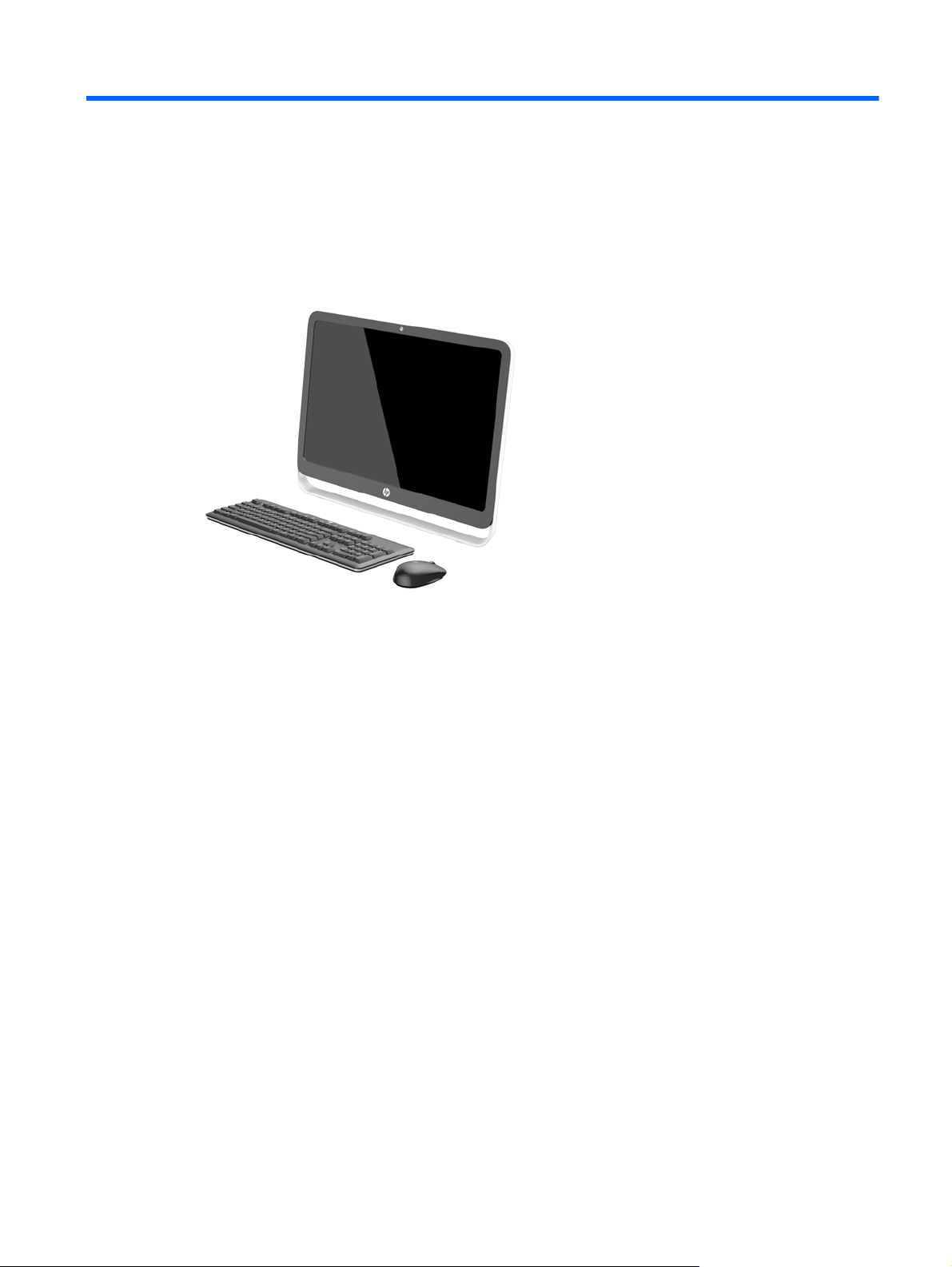
1 Product features
Overview
Figure 1-1 HP ProOne 400 G1 All-in-One
The HP ProOne 400 G1 All-in-One offers the following features:
Integrated All-in-One form factor
●
54.6-cm (21.5-inch) diagonal widescreen WLED backlit anti-glare LCD (1920 x 1080)
●
Optical touch screen
●
Adjustable tilt
●
Removable panel on the back of the computer allows users or technicians to easily and
●
efficiently service the PC
VESA mounting holes (100 mm x 100 mm)
●
●
4th generation Intel
Up to 2 TB Hard Drive, 180 GB Solid State Drive, 256 GB Self-encrypting Solid State Drive, 500
●
GB Self-encrypting Drive, or 1 TB Solid State Hard Drive
Optional Tray-load HP SuperMulti DVD+/-RW SATA Optical Disc Drive, DVD-ROM Disc Drive,
●
or Slim BDXL Blu-ray Writer
Intel H81 Express chipset
●
Two SODIMM slots with up to 16 GB of DDR3 SDRAM memory and dual channel memory
●
support
Intel integrated graphics
●
®
Core™ processors
DisplayPort video out (with audio) for second display support
●
Serial port
●
Overview 1
Page 8

DP audio, DP to VGA/DVI/HDMI dongle support
●
● Integrated Realtek RTL8151GH-CG GbE Ethernet Controller
Wireless connectivity (optional):
●
Intel Dual Band Wireless-N 7260, 802.11 a/b/g/n
◦
◦
WLAN and Bluetooth Combo Card, 802.11 a/b/g/n Bluetooth
Optional integrated webcam and dual microphone array
●
● Premium stereo speakers
● Optional 5-in-1 media card reader
6 USB ports: 1 USB 3.0, 1 USB 3.0 (fast-charging), 4 USB 2.0
●
Choice of wired or wireless keyboard and mouse
●
Wired USB keyboard and mouse
◦
HP USB–PS/2 washable keyboard and mouse
◦
Wireless keyboard and mouse
◦
●
Windows
Up to 89-percent energy-efficient external power supply
●
●
ENERGY STAR
®
7 Professional 32-bit or 64-bit or Windows® 8.1 Professional 64-bit operating system
®
qualified, EPEAT® Gold registered
®
4.0
For more information, go to
http://www.hp.com/go/productbulletin and search for your specific
computer model to find the model-specific QuickSpecs.
2 Chapter 1 Product features
Page 9
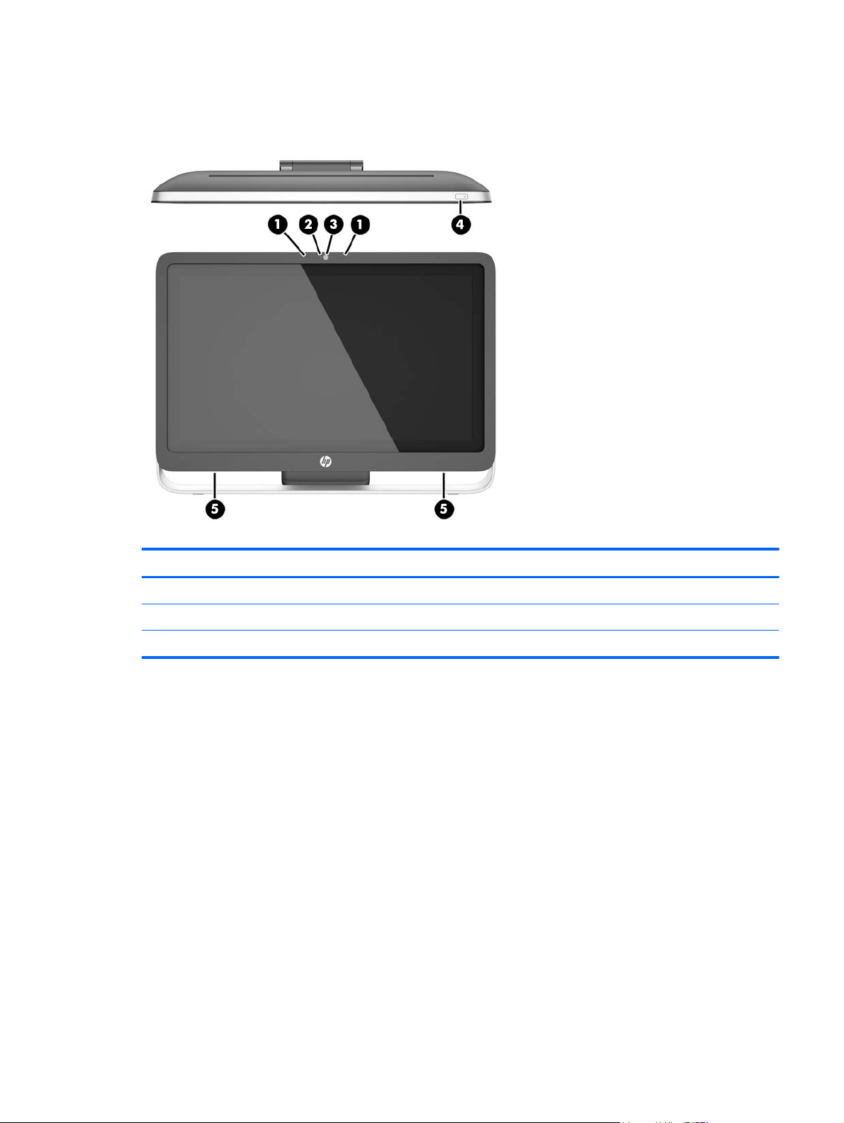
Front components
Figure 1-2 Front components
Table 1-1 Front Components
Component Component
1 Dual microphone array (optional) 4 Power button
2 Webcam activity LED (with optional webcam) 5 High-performance stereo speakers
3 Webcam (optional)
Front components 3
Page 10
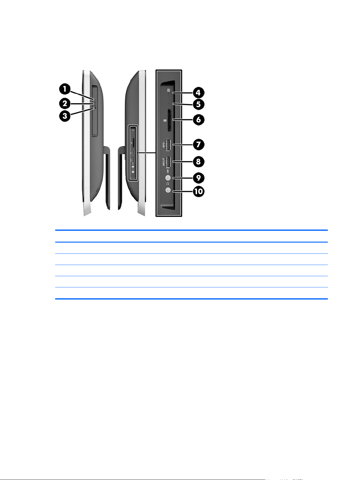
Side components
Figure 1-3 Side components
Table 1-2 Side components
Component Component
1 Tray-load optical disc drive 6 HP 5-in-1 media card reader (optional)
2 Optical disc drive eject button 7 USB 3.0 port
3 Optical disc drive activity LED 8 USB 3.0 port, fast-charging
4 Hard disc drive activity LED 9 Microphone jack
5 HP 5-in-1 medial card reader (optional) LED 10 Headphone jack
4 Chapter 1 Product features
Page 11
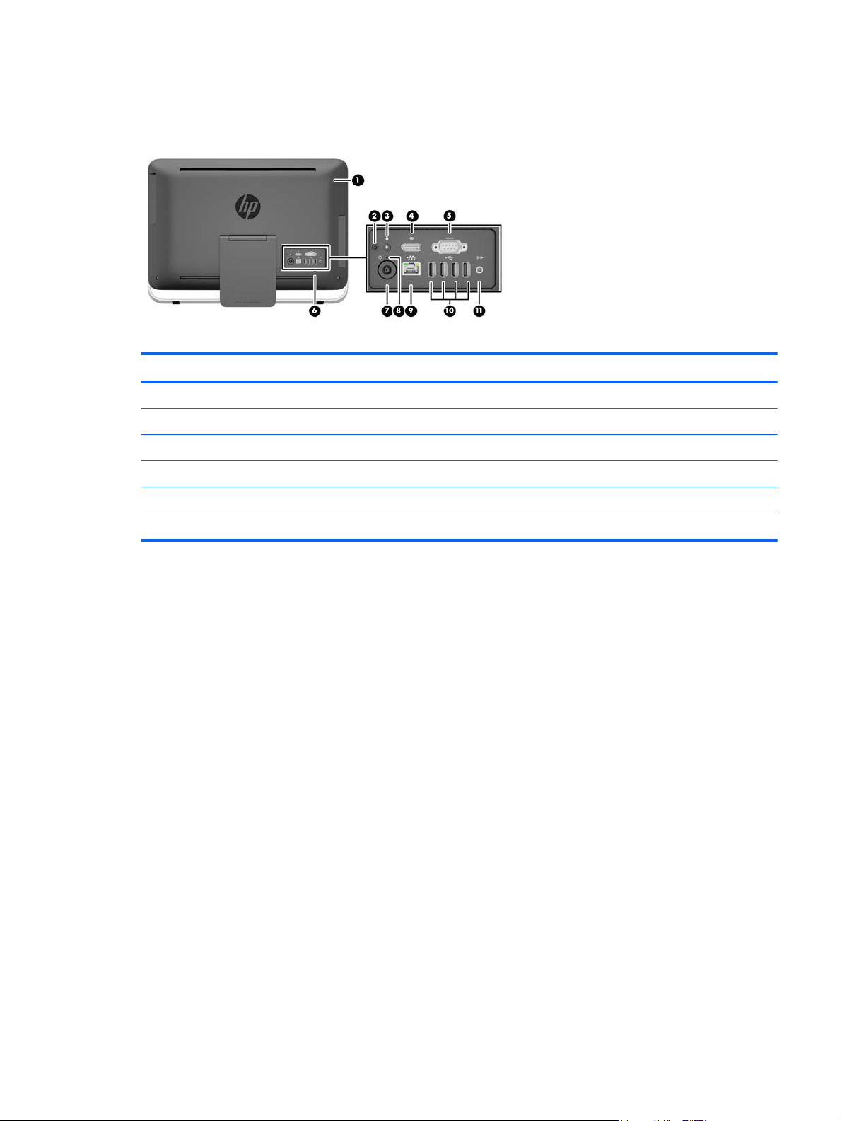
Rear components
Figure 1-4 Rear components
Table 1-3 Rear components
Component Component
1 Access panel 7 Power supply connector
2 Access panel security screw (storage position) 8 Power supply DC-in activity LED
3 Security screw hole (locking position) 9 RJ-45 Gigabit Ethernet port
4 DisplayPort port 10 (4) USB 2.0 ports
5 Serial port 11 Stereo audio line out
6 Cable lock slot
Rear components 5
Page 12
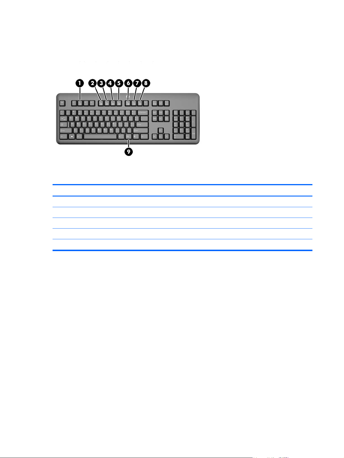
Keyboard features
Figure 1-5 Keyboard features
Table 1-4 Keyboard features
Component Component
1 Sleep 6 Mute Volume
2 Fast Reverse 7 Decrease Volume
3 Play/Pause 8 Increase Volume
4 Stop 9 Function
5Fast Forward
6 Chapter 1 Product features
Page 13

Adjusting the stand
This stand allows you to tilt the computer backward from 10 degrees to 25 degrees to set it to a
comfortable angle.
Figure 1-6 Adjusting tilt
Waking the computer
To wake the HP ProOne 400 G1 All-in-One:
To wake the computer from standby using the touch feature, swipe the screen or touch the
▲
screen and hold for at least two seconds.
To wake the computer from hibernation, press and release the power button.
▲
This affects the HP ProOne 400 G1 All-in-One equipped with one of the following operating systems:
Windows 8 (all editions, 64-bit)
●
Windows 7 (all editions, 32-bit and 64-bit)
●
Adjusting the stand 7
Page 14
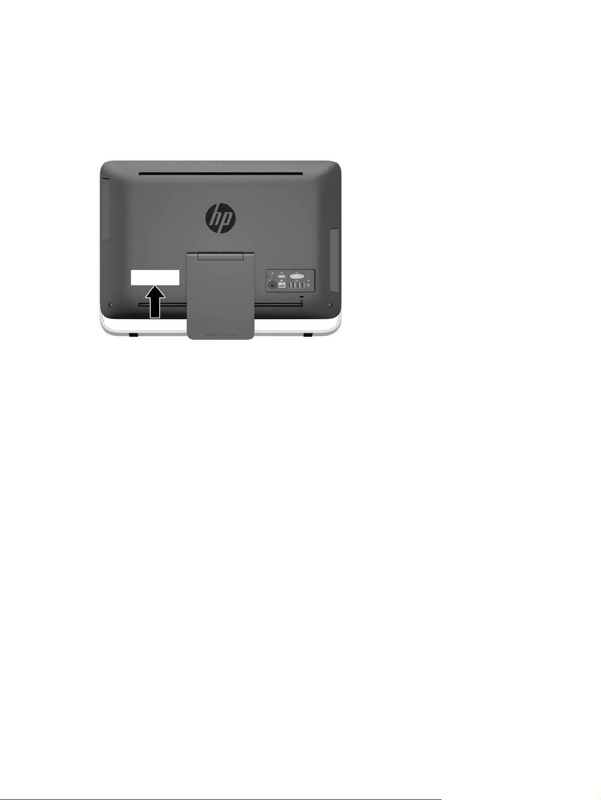
Serial number location
The computer has a unique serial number and a product ID number that are located on the exterior of
the computer. Keep these numbers available for use when contacting customer service for
assistance.
Figure 1-7 Locating the serial number
8 Chapter 1 Product features
Page 15

2 Display options
Adjusting the audio signal
There is no hardware volume control button on the HP ProOne 400 G1 AiO. (However, some
●
keyboards do have volume function buttons.)
● Volume can be adjusted with the operating system (OS) master control or the software (SW)
audio player control.
The OS master control and SW audio player control are independent. However, they are both
●
simultaneously active and affect the overall volume of the audio signal.
If the audio signal is not audible, check the OS master control and SW audio player control to be
●
sure that neither is set too low.
Adjusting display brightness
The HP ProOne 400 G1 AiO backlight brightness settings control the overall brightness of the internal
display panel only.
Windows 7 and Windows 8 each offer two methods for controlling the backlight brightness of the
internal display panel. These two options adjust the backlight brightness from 100% down to 30% of
the full backlight brightness.
Windows 7
1. Select Control Panel > Power Options.
2. Move the screen brightness slider at the bottom of the window to make adjustments.
– or –
1. Click Start > Programs > Productivity and Tools > HP My Display.
2. Select Adjust.
3. Move the slider to make adjustments.
4. At the bottom of the window, click Apply or OK to save the changes.
Windows 8
1. Point to the upper-right of the Start screen to display the Charms menu.
2. Click Settings.
3. In the lower corner of the right panel, click Brightness.
4. Move the slider to make adjustments.
– or –
1. From the desktop window, point to the task bar at the lower edge of the screen.
2. Click the Show hidden icons arrow then click the HP My Display icon.
3. Select Adjust.
Adjusting the audio signal 9
Page 16

4. Move the slider to make adjustments.
5. At the bottom of the window, click Apply or OK to save the changes.
10 Chapter 2 Display options
Page 17

3 Hardware repair and upgrade
Warnings and cautions
Before performing upgrades be sure to carefully read all of the applicable instructions, cautions, and
warnings in this guide.
WARNING! To reduce the risk of personal injury from electrical shock, hot surfaces, or fire:
Disconnect the power cord from the wall outlet and allow the internal system components to cool
before touching.
Do not plug telecommunications or telephone connectors into the network interface controller (NIC)
receptacles.
Do not disable the power cord grounding plug. The grounding plug is an important safety feature.
Plug the power cord in a grounded (earthed) outlet that is easily accessible at all times.
For your safety, do not place anything on power cords or cables. Arrange them so that no one may
accidentally step on or trip over them. Do not pull on a cord or cable. When unplugging from the
electrical outlet, grasp the cord by the plug.
To reduce the risk of serious injury, read the Safety & Comfort Guide. It describes proper workstation,
setup, posture, and health and work habits for computer users, and provides important electrical and
mechanical safety information. This guide is located on the Web at
http://www.hp.com/ergo.
WARNING! Computers that are inappropriately situated on dressers, bookcases, shelves, desks,
speakers, chests, or carts may fall over and cause personal injury.
Care should be taken to route all cords and cables connected to the computer so that they can not be
pulled, grabbed, or tripped over.
WARNING! Energized and moving parts inside.
Disconnect power to the equipment before removing the access panel.
Replace and secure the access panel before reenergizing the equipment.
CAUTION: Static electricity can damage the electrical components of the computer or optional
equipment. Before beginning these procedures, be sure that you are discharged of static electricity by
briefly touching a grounded metal object. See
information.
When the computer is plugged into an AC power source, voltage is always applied to the system
board. You must disconnect the power cord from the power source before opening the computer to
prevent damage to internal components.
Additional information
For more information on removing and replacing hardware components, the Computer Setup utility,
and troubleshooting, refer to the Maintenance and Service Guide (available in English only) for your
computer model at
http://www.hp.com.
Electrostatic discharge on page 48 for more
Warnings and cautions 11
Page 18
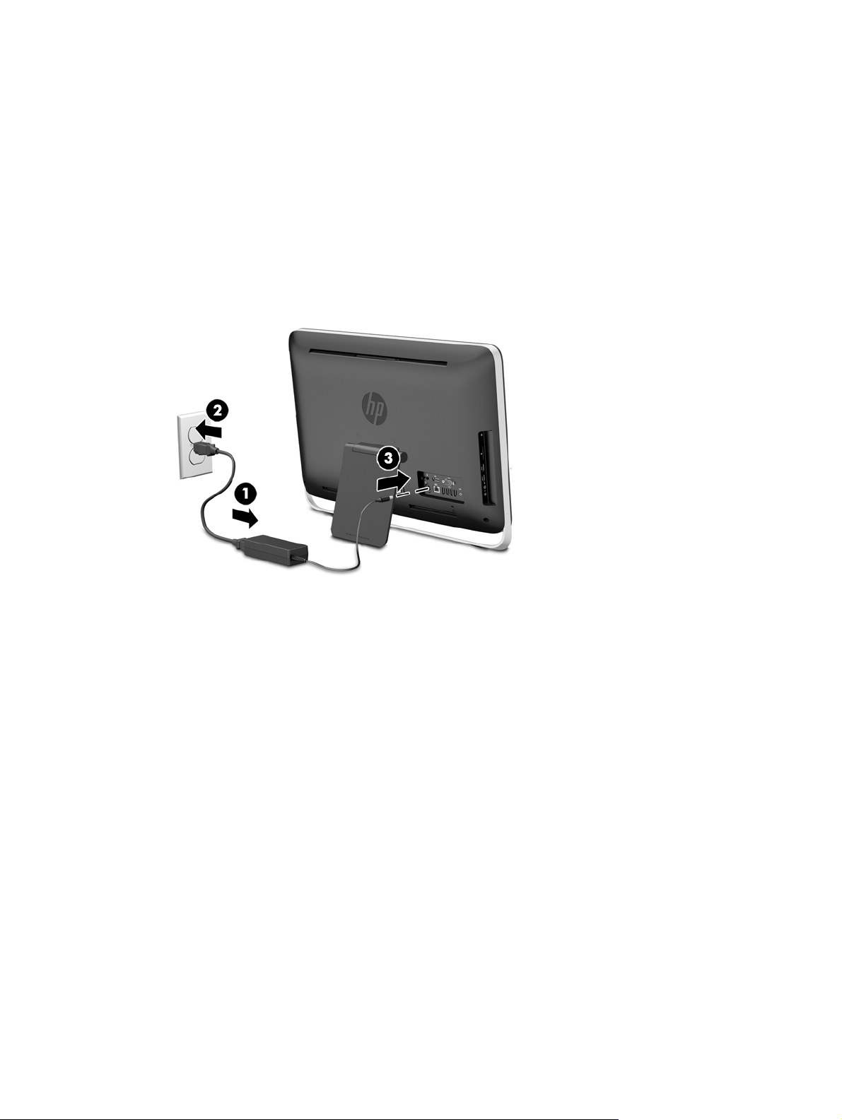
Connecting and disconnecting power
Connecting power
1. Connect the peripheral cables to the appropriate ports.
2. Plug the female end of the power cord into the power supply brick (1).
3. Connect the other end of the power cord to an electrical outlet (2).
4. Connect the round end of the power supply cord to the power supply connector on the rear of
the computer (3).
Figure 3-1 Connecting power
5. Press the power button on the top of the computer to turn it on.
Disconnecting power
1. Remove all removable media, such as optical discs or USB flash drives, from the computer.
2. Turn off the computer properly through the operating system, then turn off any external devices.
3. Remove the cable lock, if one is installed on the rear of the computer.
4. Disconnect the power cord from the power supply connector on the rear of the computer.
12 Chapter 3 Hardware repair and upgrade
Page 19

Installing a cable lock
The cable lock slot enables you to secure your computer. A cable lock is a key lock device that has a
wire cable attached. You attach one end of the cable to your desk (or other stationary object) and the
other end of the cable to the cable lock slot on back of the computer. Secure the cable lock with the
key.
Figure 3-2 Installing a cable lock
Installing a cable lock 13
Page 20

Installing an access panel security screw
You may prevent access to internal components by securing the access panel. Remove the T15
tamper-resistant Torx security screw from the storage position in the rear of the computer and screw
it into the security screw hole (locking position) to prevent removal of the access panel.
Figure 3-3 Securing the access panel
14 Chapter 3 Hardware repair and upgrade
Page 21

Synchronizing the optional wireless keyboard and mouse
The optional wireless keyboard and mouse are easy to set up. Just remove the battery tabs on both
the keyboard and the mouse to activate the preinstalled batteries.
NOTE: For better mouse battery life and performance, avoid using your mouse on a dark or high-
gloss surface, and turn mouse power off when not in use.
To synchronize the wireless keyboard and mouse:
1. Make sure the keyboard and mouse are next to the computer, within 30 cm (1 foot) and away
from interference from other devices.
2. Turn on the computer.
3. Make sure the Power switch on the bottom of the mouse is in the On position.
4. Insert the wireless receiver into a USB port on the computer.
Figure 3-4 Installing the wireless receiver
5. Press and hold the Connect button on the wireless receiver for five seconds until the blue activity
LED begins blinking.
NOTE: When the blue activity LED begins blinking, you have 30 seconds to synchronize the
mouse with the wireless receiver.
6. Press and release the Connect button on the bottom of the mouse. The blue activity LED from
the wireless receiver turns off when synchronization is complete.
NOTE: If the Connect button on the bottom of the mouse is pressed again, the synchronization
of the wireless receiver and the mouse will be broken. Turn the mouse off, then on again to
restore the synchronization.
NOTE: If the procedure does not work, remove and then reinsert the wireless keyboard and mouse
receiver from the back of the computer and then synchronize the keyboard and mouse again. If
synchronization still does not work, remove and replace the batteries.
Synchronizing the optional wireless keyboard and mouse 15
Page 22

Removing batteries from the optional wireless keyboard or mouse
NOTE: The wireless keyboard and mouse are optional components.
To remove batteries from the wireless keyboard, remove the battery door on the underside of the
keyboard (1) and lift the batteries out of the battery compartment (2).
Figure 3-5 Removing batteries from the wireless keyboard
To remove batteries from the wireless mouse, remove the battery door on the underside of the mouse
(1) and lift the batteries out of the battery compartment (2).
Figure 3-6 Removing batteries from the wireless mouse
16 Chapter 3 Hardware repair and upgrade
Page 23

Attaching the computer to a mounting fixture
The computer stand is secured to a VESA mount inside the computer chassis. You can remove the
stand and install the computer on a wall, monitor arm, or other mounting fixture.
Table 3-1 Computer dimensions (without stand)
Computer dimensions (without stand)
Height 362.9 mm 14.3 in
Width 557.9 mm 22.0 in
Depth 59.4 mm 2.3 in
Computer weight (without stand)
Minimum configuration 7.42 kg 16.4 lb
With Options 7.57 kg 16.7 lb
VESA standard hole patterns
height x width 100 mm x 100 mm 3.94 in x 3.94 in
To remove the stand:
1. Remove all removable media, such as optical discs or USB flash drives, from the computer.
2. Turn off the computer properly through the operating system, then turn off any external devices.
3. Disconnect the power cord from the power outlet and disconnect any external devices.
CAUTION: Regardless of the power-on state, voltage is always present on the system board
as long as the system is plugged into an active AC outlet. You must disconnect the power cord
to avoid damage to the internal components of the computer.
4. Remove/disengage any security devices that prohibit opening the computer.
5. Place the computer face down on a soft flat surface. HP recommends that you set down a
blanket, towel, or other soft cloth to protect the bezel and screen surface from scratches or other
damage.
6. Loosen the two captive screws at the bottom of the computer (1) to release the bottom edge of
the access panel.
Attaching the computer to a mounting fixture 17
Page 24

7. Rotate the bottom edge of the access panel up (2), and then lift the access panel off of the
computer (3).
Figure 3-7 Removing the access panel
8. Place the access panel down on a flat surface with the inside of the panel facing up.
9. Remove the three screws (1) securing the stand to the access panel, and then remove the stand
(2).
Figure 3-8 Removing the stand
NOTE: Save the screws together with the stand in case they are needed in the future.
10. Set the top edge of the access panel down on the top edge of the computer chassis (1). Be sure
to align the hooks on the underside of the top edge of the access panel with the top edge of the
computer.
11. Rotate the bottom edge of the access panel down (2) and press it firmly onto the chassis until it
locks into place.
18 Chapter 3 Hardware repair and upgrade
Page 25

12. Tighten the captive screws (3) to secure the access panel in place.
Figure 3-9 Replacing the access panel
The computer is now ready to be mounted to a wall, monitor arm, or other mounting fixture.
Connecting a second display
The DisplayPort connector on the rear of the computer allows you to connect a second display to the
computer.
If you are adding a second display that has a DisplayPort connector, then no DisplayPort video
adapter is required. If you are adding a second display that does not have a DisplayPort connector,
you can purchase a DisplayPort video adaptor from HP for your configuration.
DisplayPort adapters and video cables are purchased separately. HP offers the following adapters:
DisplayPort to VGA adapter
●
DisplayPort to DVI adapter
●
DisplayPort to HDMI adapter
●
To connect a second display:
1. Turn off power to the computer and the second display that you are connecting to the computer.
Connecting a second display 19
Page 26

2. If your second display has a DisplayPort connector, connect a DisplayPort cable directly
between the DisplayPort connector on the rear of the computer and the DisplayPort connector
on the second display.
Figure 3-10 Connecting a second display using a DisplayPort cable
3. If your second display does not have a DisplayPort connector, connect a DisplayPort video
adapter to the DisplayPort connector of the computer. Then connect a cable (VGA, DVI. or
HDMI, depending on your application) between the adapter and the second display.
Figure 3-11 Connecting a second display using a DisplayPort adapter
4. Turn on power to the computer and the second display.
NOTE: Use the graphics card software or the Windows Display Settings to configure the second
display as a mirrored image of the primary display or an extension of the primary display.
20 Chapter 3 Hardware repair and upgrade
Page 27

Locating internal components
The following sections contain procedures for removing and replacing these internal components:
Optical disc drive
●
Hard disc drive, solid state drive, or self-encrypting drive
●
Battery
●
Memory
●
Figure 3-12 Locating internal components
Component Component
1 Optical disc drive 3 Battery
2 Hard disc drive 4 Memory
Removing and installing memory
The computer comes with double data rate 3 synchronous dynamic random access memory (DDR3SDRAM) small outline dual inline memory modules (SODIMMs).
SODIMMs
The memory sockets on the system board can be populated with up to two industry-standard
SODIMMs. These memory sockets are populated with at least one preinstalled SODIMM. To achieve
the maximum memory support, you can populate the system board with up to 16 GB of memory.
DDR3-SDRAM SODIMMs
For proper system operation, the SODIMMs must be:
industry-standard 204-pin
●
unbuffered non-ECC PC3-10600 DDR3-1600 MHz-compliant
●
1.5 volt DDR3-SDRAM SODIMMs
●
Locating internal components 21
Page 28

The DDR3-SDRAM SODIMMs must also:
● support CAS latency 11 DDR3 1600 MHz (11-11-11 timing)
contain the mandatory Joint Electronic Device Engineering Council (JEDEC) specification
●
In addition, the computer supports:
● 1-Gbit, 2-Gbit, and 4-Gbit non-ECC memory technologies
● single-sided and double-sided SODIMMS
SODIMMs constructed with x8 and x16 SDRAMs; SODIMMs constructed with x4 SDRAMs are
●
not supported
NOTE: The system will not operate properly if you install unsupported SODIMM memory.
HP offers upgrade memory for this computer and advises that the consumer purchase it to avoid
compatibility issues with unsupported third-party memory.
22 Chapter 3 Hardware repair and upgrade
Page 29

Populating SODIMM sockets
The system will automatically operate in single channel mode, dual channel mode, or flex mode,
depending on how the SODIMMs are installed. Refer to the following table to identify the SODIMM
channel locations.
Table 3-2 Identifying SODIMM locations
Location System board label Channel
Lower Socket SODIMM1 Channel A
Upper Socket SODIMM3 Channel B
The system will operate in single channel mode if the SODIMM sockets are populated in one
●
channel only.
The system will operate in flex mode if the memory capacity of the SODIMM in Channel A is not
●
equal to the memory capacity of the SODIMM in Channel B. In flex mode, the channel populated
with the least amount of memory describes the total amount of memory assigned to dual
channel and the remainder is assigned to single channel. If one channel will have more memory
than the other, the larger amount should be assigned to channel A.
The system will operate in a higher-performing dual channel mode if the memory capacity of the
●
SODIMM in Channel A is equal to the memory capacity of the SODIMM in Channel B.
In any mode, the maximum operational speed is determined by the slowest SODIMM in the
●
system.
Installing SODIMMs
There are two memory sockets on the system board. To remove or install memory modules:
1. Remove all removable media, such as optical discs or USB flash drives, from the computer.
2. Turn off the computer properly through the operating system, then turn off any external devices.
3. Disconnect the power cord from the power outlet and disconnect any external devices.
CAUTION: You must disconnect the power cord and wait approximately 30 seconds for the
power to drain before adding or removing memory modules. Regardless of the power-on state,
voltage is always supplied to the memory modules as long as the computer is plugged into an
active AC outlet. Adding or removing memory modules while voltage is present may cause
irreparable damage to the memory modules or system board.
4. Remove/disengage any security devices that prohibit opening the computer.
5. Place the computer face down on a soft flat surface. HP recommends that you set down a
blanket, towel, or other soft cloth to protect the bezel and screen surface from scratches or other
damage.
6. Loosen the two captive screws at the bottom of the computer (1) to release the bottom edge of
the access panel.
Removing and installing memory 23
Page 30

7. Rotate the bottom edge of the access panel up (2), and then lift the access panel off of the
computer (3).
Figure 3-13 Removing the access panel
8. Remove the three screws securing the VESA panel to the chassis (1), and then lift the panel out
of the chassis (2).
Figure 3-14 Removing the VESA panel
9. Remove the two screws securing the fire enclosure shield to the chassis (1).
24 Chapter 3 Hardware repair and upgrade
Page 31

10. Rotate the shield to the right (2), and then lift it off the chassis (3).
Figure 3-15 Removing the fire enclosure shield
The memory modules can now be seen in the right side of the chassis.
Figure 3-16 Locating the memory modules
Removing and installing memory 25
Page 32

11. To remove a memory module, press outward on the two latches on each side of the SODIMM
(1), then pull the SODIMM out of the socket (2).
Figure 3-17 Removing a memory module
12. To install a memory module, slide the SODIMM into the socket at approximately a 30° angle (1),
then press the SODIMM down (2) so that the latches lock it in place.
Figure 3-18 Installing a memory module
NOTE: A memory module can be installed in only one way. Match the notch on the module
with the tab on the memory socket.
13. Engage the three tabs on the right edge of the fire enclosure shield with the matching slots on
the right side of the chassis and rotate the fire enclosure shield down onto the chassis.
14. Fasten the two screws to secure the fire enclosure shield to the chassis.
15. Place the VESA panel onto the chassis and fasten the three screws to secure the VESA panel to
the chassis.
16. Set the top edge of the access panel down on the top edge of the computer chassis (1). Be sure
to align the hooks on the underside of the top edge of the access panel with the top edge of the
computer.
26 Chapter 3 Hardware repair and upgrade
Page 33

17. Rotate the bottom edge of the access panel down (2) and press it firmly onto the chassis until it
locks into place.
18. Tighten the captive screws (3) to secure the access panel in place.
Figure 3-19 Replacing the access panel
19. Place the computer in the upright position.
20. Reconnect the power cord and external devices.
21. Lock any security devices that were disengaged when the access panel was removed.
22. Turn on the computer. The computer automatically recognizes the additional memory when you
turn on the computer.
Replacing the battery
The battery is located on the system board on the left side of the memory modules. The battery that
comes with the computer provides power to the real-time clock. When replacing the battery, use a
battery equivalent to the battery originally installed in the computer. The computer comes with a 3-volt
lithium coin cell battery.
WARNING! The computer contains an internal lithium manganese dioxide battery. There is a risk of
fire and burns if the battery is not handled properly. To reduce the risk of personal injury:
Do not attempt to recharge the battery.
Do not expose to temperatures higher than 60 °C (140 ºF).
Do not disassemble, crush, puncture, short external contacts, or dispose of in fire or water.
Replace the battery only with the HP spare designated for this product.
CAUTION: Before replacing the battery, it is important to back up the computer CMOS settings.
When the battery is removed or replaced, the CMOS settings will be cleared.
Static electricity can damage the electronic components of the computer or optional equipment.
Before beginning these procedures, be sure that you are discharged of static electricity by briefly
touching a grounded metal object.
Replacing the battery 27
Page 34

NOTE: The lifetime of the lithium battery can be extended by plugging the computer into a live AC
wall socket. The lithium battery is only used when the computer is NOT connected to AC power.
HP encourages customers to recycle used electronic hardware, HP original print cartridges, and
rechargeable batteries. For more information about recycling programs, go to
http://www.hp.com/
recycle.
1. Remove all removable media, such as optical discs or USB flash drives, from the computer.
2. Turn off the computer properly through the operating system, then turn off any external devices.
3. Disconnect the power cord from the power outlet and disconnect any external devices.
CAUTION: Regardless of the power-on state, voltage is always present on the system board
as long as the system is plugged into an active AC outlet. You must disconnect the power cord
to avoid damage to the internal components of the computer.
4. Remove/disengage any security devices that prohibit opening the computer.
5. Place the computer face down on a soft flat surface. HP recommends that you set down a
blanket, towel, or other soft cloth to protect the bezel and screen surface from scratches or other
damage.
6. Loosen the two captive screws at the bottom of the computer (1) to release the bottom edge of
the access panel.
7. Rotate the bottom edge of the access panel up (2), and then lift the access panel off of the
computer (3).
Figure 3-20 Removing the access panel
28 Chapter 3 Hardware repair and upgrade
Page 35

8. Remove the three screws securing the VESA panel to the chassis (1), and then lift the panel out
of the chassis (2).
Figure 3-21 Removing the VESA panel
9. Remove the two screws securing the fire enclosure shield to the chassis (1).
Replacing the battery 29
Page 36

10. Rotate the shield to the right (2), and then lift it off the chassis (3).
Figure 3-22 Removing the fire enclosure shield
The battery can now be seen on the left side of the memory modules.
Figure 3-23 Locating the battery
11. To release the battery from its holder, insert a thin metal instrument into the slot on the side of
the holder below the battery (1) and pry the battery up and out of the holder (2).
30 Chapter 3 Hardware repair and upgrade
Page 37

12. To insert the new battery, slide one edge of the replacement battery under the holder’s lip with
the positive side up (1) and press the other edge down into the holder so that it snaps in place
(2).
Figure 3-24 Removing and Replacing a Coin Cell Battery (Type 1)
13. Engage the three tabs on the right edge of the fire enclosure shield with the matching slots on
the right side of the chassis and rotate the fire enclosure shield down onto the chassis.
14. Fasten the two screws to secure the fire enclosure shield to the chassis.
15. Place the VESA panel onto the chassis and fasten the three screws to secure the VESA panel to
the chassis.
16. Set the top edge of the access panel down on the top edge of the computer chassis (1). Be sure
to align the hooks on the underside of the top edge of the access panel with the top edge of the
computer.
17. Rotate the bottom edge of the access panel down (2) and press it firmly onto the chassis until it
locks into place.
18. Tighten the captive screws (3) to secure the access panel in place.
Figure 3-25 Replacing the access panel
19. Place the computer in the upright position.
20. Reconnect the power cord and external devices.
21. Lock any security devices that were disengaged when the access panel was removed.
Replacing the battery 31
Page 38

22. Turn on the computer.
23. Reset the date and time, your passwords, and any special system setups using Computer
Setup.
Replacing drives
Replacing a hard drive
The hard drive is located behind the access panel on the lower left side of the computer (when
viewed from behind). The drive is housed in a removable cage.
Any one of the following may be installed in the computer:
One 3.5-inch hard drive
●
One 2.5-inch solid state drive (SSD), self-encrypting drive (SED), or solid state hybrid drive
●
(SSHD)
NOTE: The 2.5-inch drive option kit from HP also contains the adapter required to install this
drive.
Removing a hard drive
●
Installing a hard drive
●
Removing a hard drive
Removing a 3.5-inch hard drive
●
Removing a 2.5-inch solid state drive (SSD), self-encrypting drive (SED), or solid state hybrid
●
drive (SSHD)
Removing a 3.5-inch hard drive
1. Remove all removable media, such as optical discs or USB flash drives, from the computer.
2. Turn off the computer properly through the operating system, then turn off any external devices.
3. Disconnect the power cord from the power outlet and disconnect any external devices.
CAUTION: Regardless of the power-on state, voltage is always present on the system board
as long as the system is plugged into an active AC outlet. You must disconnect the power cord
to avoid damage to the internal components of the computer.
4. Remove/disengage any security devices that prohibit opening the computer.
5. Place the computer face down on a soft flat surface. HP recommends that you set down a
blanket, towel, or other soft cloth to protect the bezel and screen surface from scratches or other
damage.
6. Loosen the two captive screws at the bottom of the computer (1) to release the bottom edge of
the access panel.
32 Chapter 3 Hardware repair and upgrade
Page 39

7. Rotate the bottom edge of the access panel up (2), and then lift the access panel off of the
computer (3).
Figure 3-26 Removing the access panel
The hard drive cage can now be seen in the lower left side of the chassis.
Figure 3-27 Locating the hard drive cage
8. Loosen the captive screw securing the hard drive cage in the chassis (1).
Replacing drives 33
Page 40

9. Slide the hard drive cage left, and then lift it out of the chassis (2).
Figure 3-28 Removing the hard drive cage
10. Remove the four mounting screws (1) securing the 3.5-inch hard drive in the hard drive cage. Be
sure to keep the screws together with the blue rubber grommets to use to install a replacement
drive.
11. Slide the 3.5-inch hard drive out of the hard drive cage (2).
Figure 3-29 Removing the mounting screws
For instructions on installing a hard drive, see Installing a hard drive on page 39.
34 Chapter 3 Hardware repair and upgrade
Page 41

Removing a 2.5-inch solid state drive (SSD), self-encrypting drive (SED), or solid state hybrid drive
(SSHD)
1. Remove all removable media, such as optical discs or USB flash drives, from the computer.
2. Turn off the computer properly through the operating system, then turn off any external devices.
3. Disconnect the power cord from the power outlet and disconnect any external devices.
CAUTION: Regardless of the power-on state, voltage is always present on the system board
as long as the system is plugged into an active AC outlet. You must disconnect the power cord
to avoid damage to the internal components of the computer.
4. Remove/disengage any security devices that prohibit opening the computer.
5. Place the computer face down on a soft flat surface. HP recommends that you set down a
blanket, towel, or other soft cloth to protect the bezel and screen surface from scratches or other
damage.
6. Loosen the two captive screws at the bottom of the computer (1) to release the bottom edge of
the access panel.
Replacing drives 35
Page 42

7. Rotate the bottom edge of the access panel up (2), and then lift the access panel off of the
computer (3).
Figure 3-30 Removing the access panel
The hard drive cage can now be seen in the lower left side of the chassis.
Figure 3-31 Locating the hard drive cage
8. Loosen the captive screw securing the hard drive cage in the chassis (1).
36 Chapter 3 Hardware repair and upgrade
Page 43

9. Slide the hard drive cage left, and then lift it out of the chassis (2).
Figure 3-32 Removing the hard drive cage
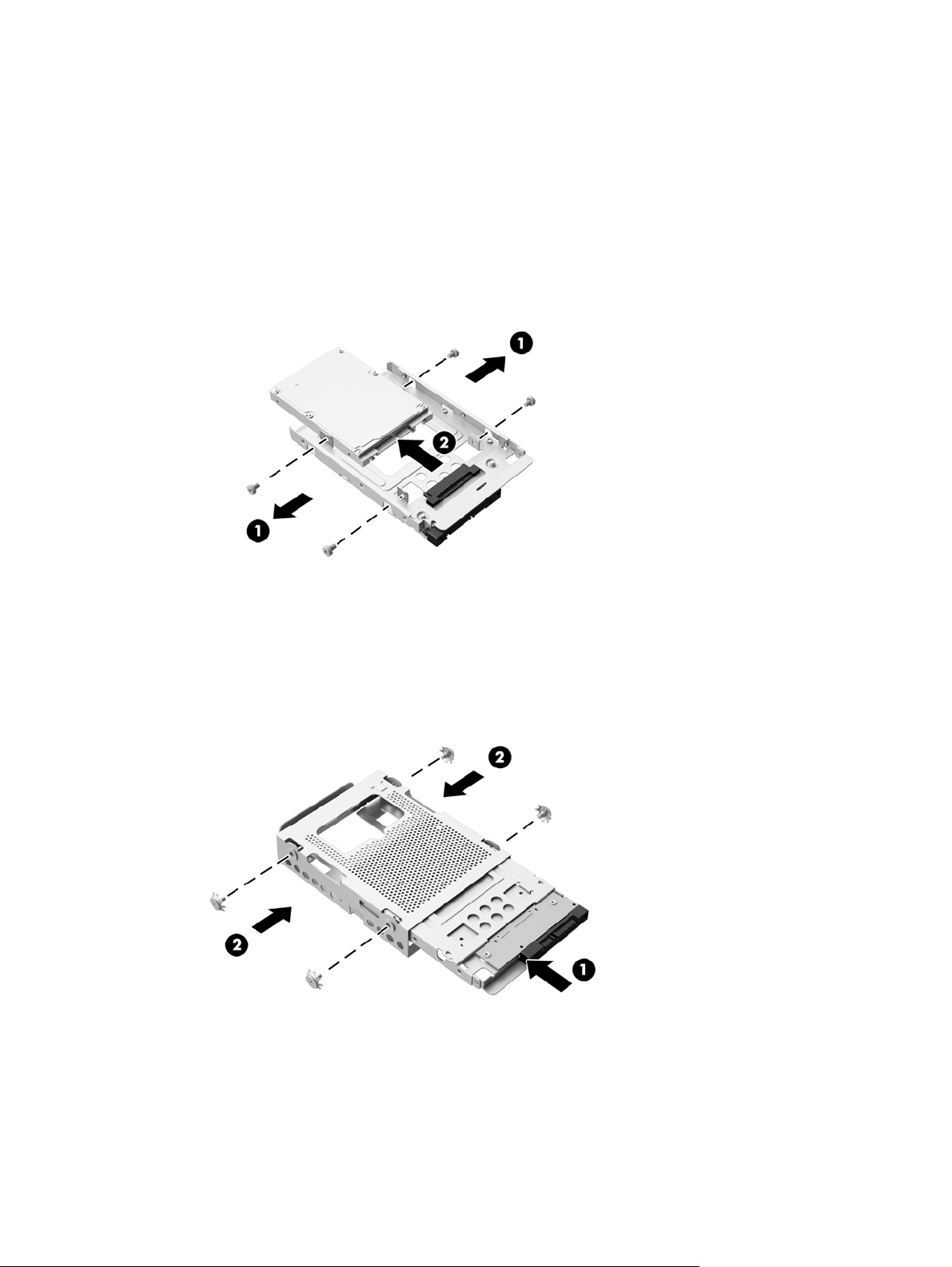
10. Remove the four mounting screws (1) securing the 2.5-inch drive adapter in the hard drive cage.
Be sure to keep the screws together with the blue rubber grommets to use to install a
replacement drive.
11. Slide the 2.5-inch drive adapter out of the hard drive cage (2).
Figure 3-33 Removing the drive cage
12. Remove the four screws (1) securing the 2.5-inch drive in the drive adapter. Be sure to keep the
screws to use to install a replacement drive.
Replacing drives 37
Page 44

13. Slide the 2.5-inch hard drive out of the drive adapter (2).
Figure 3-34 Removing the 2.5-inch drive adapter from the drive cage
For instructions on installing a hard drive, see Installing a hard drive on page 39.
38 Chapter 3 Hardware repair and upgrade
Page 45

Installing a hard drive
Installing a 3.5-inch hard drive
●
●
Installing a 2.5-inch solid state drive (SSD), self-encrypting drive (SED), or solid state hybrid
drive (SSHD)
Installing a 3.5-inch hard drive
1. Slide the new 3.5-inch hard drive into the hard drive cage (1). Be sure that the hard drive
connector is facing up at the open end of the drive.
2. Screw the four mounting screws through the sides of the hard drive cage into the 3.5-inch hard
drive (2). Be sure to keep the blue rubber grommets behind each screw.
Figure 3-35 Installing the 3.5-inch hard drive in the hard drive cage
3. With the 3.5-inch hard drive connector facing toward the center of the chassis, place the hard
drive cage into the chassis and slide it toward the center until it snaps into place (1).
4. Tighten the captive screw (2) to secure the hard drive cage in the chassis.
Figure 3-36 Installing the hard drive cage
Replacing drives 39
Page 46

5. Set the top edge of the access panel down on the top edge of the computer chassis (1). Be sure
to align the hooks on the underside of the top edge of the access panel with the top edge of the
computer.
6. Rotate the bottom edge of the access panel down (2) and press it firmly onto the chassis until it
locks into place.
7. Tighten the captive screws (3) to secure the access panel in place.
Figure 3-37 Replacing the access panel
8. Place the computer in the upright position.
9. Reconnect the power cord and external devices.
10. Lock any security devices that were disengaged when the access panel was removed.
11. Turn on the computer.
40 Chapter 3 Hardware repair and upgrade
Page 47
Installing a 2.5-inch solid state drive (SSD), self-encrypting drive (SED), or solid state hybrid drive
(SSHD)
1. Insert the 2.5-inch solid state drive (SSD), self-encrypting drive (SED), or solid state hybrid drive
(SSHD) into the 2.5-inch drive adapter (1). Be sure that the connector is at the opening of the
adapter.
2. Fasten the four screws (2) to secure the 2.5-inch solid state drive (SSD), self-encrypting drive
(SED), or solid state hybrid drive (SSHD) in the 2.5-inch drive adapter.
Figure 3-38 Securing the 2.5-inch hard drive in the adapter
3. Slide the 2.5-inch drive adapter into the hard drive cage (1).
4. Screw the four mounting screws with grommets through the sides of the hard drive cage into the
2.5-inch drive adapter (2). Be sure to keep the blue rubber grommets behind each screw.
Figure 3-39 Installing the 2.5-inch drive adapter in the hard drive cage
5. With the 2.5-inch drive connector facing toward the center of the chassis, place the drive cage
into the chassis and slide it toward the center until it snaps into place (1).
Replacing drives 41
Page 48
6. Tighten the captive screw (2) to secure the hard drive cage in the chassis.
Figure 3-40 Installing the hard drive cage
7. Set the top edge of the access panel down on the top edge of the computer chassis (1). Be sure
to align the hooks on the underside of the top edge of the access panel with the top edge of the
computer.
8. Rotate the bottom edge of the access panel down (2) and press it firmly onto the chassis until it
locks into place.
9. Tighten the captive screws (3) to secure the access panel in place.
Figure 3-41 Replacing the access panel
10. Place the computer in the upright position.
11. Reconnect the power cord and external devices.
12. Lock any security devices that were disengaged when the access panel was removed.
13. Turn on the computer.
42 Chapter 3 Hardware repair and upgrade
Page 49

Replacing the optical disc drive
The optical disc drive is located above the hard drive on the left side of the computer (when viewed
from behind).
1. Remove all removable media, such as optical discs or USB flash drives, from the computer.
2. Turn off the computer properly through the operating system, then turn off any external devices.
3. Disconnect the power cord from the power outlet and disconnect any external devices.
CAUTION: Regardless of the power-on state, voltage is always present on the system board
as long as the system is plugged into an active AC outlet. You must disconnect the power cord
to avoid damage to the internal components of the computer.
4. Remove/disengage any security devices that prohibit opening the computer.
5. Place the computer face down on a soft flat surface. HP recommends that you set down a
blanket, towel, or other soft cloth to protect the bezel and screen surface from scratches or other
damage.
6. Loosen the two captive screws at the bottom of the computer (1) to release the bottom edge of
the access panel.
Replacing drives 43
Page 50

7. Rotate the bottom edge of the access panel up (2), and then lift the access panel off of the
computer (3).
Figure 3-42 Removing the access panel
The optical disc drive can now be seen in the upper left side of the chassis.
Figure 3-43 Locating the optical disc drive
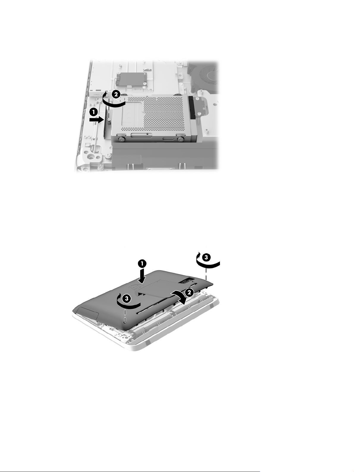
8. Loosen the captive screw (1) through the optical disc drive bracket that secures the optical disc
drive to the chassis.
NOTE: The optical disc drive bracket is installed on the chassis if the model does not have an
optical disc drive. Remove the bracket from the chassis and follow the remaining steps using two
screws from the option kit to mount the bracket to the optical disc drive.
44 Chapter 3 Hardware repair and upgrade
Page 51

9. Slide the optical disc drive left (2) to remove it from the chassis.
Figure 3-44 Removing the optical disc drive
10. Remove the two screws attaching the optical disc drive bracket to the optical disc drive.
Figure 3-45 Removing the optical disc drive bracket
Replacing drives 45
Page 52

11. Attach the optical disc drive bracket to the new optical disc drive by screwing the two screws
through the bracket into the new drive.
Figure 3-46 Installing the optical disc drive bracket
12. Place the new optical disc drive into the chassis and push the drive in firmly until it snaps into
place (1).
NOTE: The optical disc drive can be installed in only one way.
13. Tighten the captive screw (2) through the optical disc drive bracket to secure the drive to the
chassis.
Figure 3-47 Installing the optical disc drive
14. Set the top edge of the access panel down on the top edge of the computer chassis (1). Be sure
to align the hooks on the underside of the top edge of the access panel with the top edge of the
computer.
15. Rotate the bottom edge of the access panel down (2) and press it firmly onto the chassis until it
locks into place.
46 Chapter 3 Hardware repair and upgrade
Page 53

16. Tighten the captive screws (3) to secure the access panel in place.
Figure 3-48 Replacing the access panel
17. Place the computer in the upright position.
18. Reconnect the power cord and external devices.
19. Lock any security devices that were disengaged when the access panel was removed.
20. Turn on the computer.
Replacing drives 47
Page 54

A Electrostatic discharge
A discharge of static electricity from a finger or other conductor may damage system boards or other
static-sensitive devices. This type of damage may reduce the life expectancy of the device.
Preventing electrostatic damage
To prevent electrostatic damage, observe the following precautions:
Avoid hand contact by transporting and storing products in static-safe containers.
●
Keep electrostatic-sensitive parts in their containers until they arrive at static-free workstations.
●
Place parts on a grounded surface before removing them from their containers.
●
Avoid touching pins, leads, or circuitry.
●
Always be properly grounded when touching a static-sensitive component or assembly.
●
Grounding methods
There are several methods for grounding. Use one or more of the following methods when handling
or installing electrostatic-sensitive parts:
Use a wrist strap connected by a ground cord to a grounded workstation or computer chassis.
●
Wrist straps are flexible straps with a minimum of 1 megohm +/- 10 percent resistance in the
ground cords. To provide proper ground, wear the strap snug against the skin.
Use heelstraps, toestraps, or bootstraps at standing workstations. Wear the straps on both feet
●
when standing on conductive floors or dissipating floor mats.
Use conductive field service tools.
●
Use a portable field service kit with a folding static-dissipating work mat.
●
If you do not have any of the suggested equipment for proper grounding, contact an HP authorized
dealer, reseller, or service provider.
NOTE: For more information on static electricity, contact an HP authorized dealer, reseller, or
service provider.
48 Appendix A Electrostatic discharge
Page 55

B Computer operating guidelines, routine
care, and shipping preparation
Computer operating guidelines and routine care
Follow these guidelines to properly set up and care for the computer:
● Keep the computer away from excessive moisture, direct sunlight, and extremes of heat and
cold.
Operate the computer on a sturdy, level surface. Leave a 10.2-cm (4-inch) clearance on all
●
vented sides of the computer to permit the required airflow.
Never restrict the airflow into the computer by blocking any vents or air intakes.
●
Never operate the computer with any of the access panels removed.
●
Do not place computers so near each other that they are subject to each other’s recirculated or
●
preheated air.
If the computer is to be operated within a separate enclosure, intake and exhaust ventilation
●
must be provided on the enclosure, and the same operating guidelines listed above will still
apply.
Keep liquids away from the computer and keyboard.
●
Never cover the ventilation slots with any type of material.
●
● Install or enable power management functions of the operating system or other software,
including sleep states.
When cleaning the computer turn off power to the computer and unplug the power cord before
●
you do any of the following:
Wipe the exterior of the computer with a soft, damp cloth as needed. Using cleaning
◦
products may discolor or damage the finish.
◦ Do not use cleaners that contain any petroleum based materials such as benzene, thinner,
or any volatile substance to clean the screen or cabinet. These chemicals may damage the
computer.
Wipe the screen with a soft, clean antistatic cloth. For more difficult cleaning situations, use
◦
a 50/50 mix of water and Isopropyl alcohol. Spray the cleaner onto a cloth and use the
damp cloth to gently wipe the screen surface. Never spray the cleaner directly on the
screen surface. It may run behind the bezel and damage the electronics.
Occasionally clean the air vents on all vented sides of the computer. Lint, dust, and other
◦
foreign matter can block the vents and limit the airflow.
Computer operating guidelines and routine care 49
Page 56

Optical disc drive precautions
Be sure to observe the following guidelines while operating or cleaning the optical disc drive.
Do not move the drive during operation. This may cause it to malfunction during reading.
●
Avoid exposing the drive to sudden changes in temperature, as condensation may form inside
●
the unit. If the temperature suddenly changes while the drive is on, wait at least one hour before
you turn off the power. If you operate the unit immediately, it may malfunction while reading.
Avoid placing the drive in a location that is subject to high humidity, extreme temperatures,
●
mechanical vibration, or direct sunlight.
CAUTION: If any object or liquid falls into the drive, immediately unplug the computer and have it
checked by an authorized HP service provider.
Shipping preparation
Follow these suggestions when preparing to ship the computer:
1. Back up the hard drive files on optical media or external USB drives. Be sure that the backup
media is not exposed to electrical or magnetic impulses while stored or in transit.
NOTE: The hard drive locks automatically when the system power is turned off.
2. Remove and store all removable media.
3. Turn off the computer and external devices.
4. Disconnect the power cord from the electrical outlet, then from the computer.
5. Disconnect the system components and external devices from their power sources, then from
the computer.
NOTE: Be sure that all boards are seated properly and secured in the board slots before
shipping the computer.
6. Pack the system components and external devices in their original packing boxes or similar
packaging with sufficient packing material to protect them.
50 Appendix B Computer operating guidelines, routine care, and shipping preparation
Page 57

Index
A
additional information 11
adjusting
audio 9
brightness 9
audio, adjusting 9
B
battery, replacing 27
brightness, adjusting 9
C
components
front 3
internal 21
rear 5
side 4
computer operating guidelines 49
D
display
adjusting audio 9
adjusting brightness 9
DisplayPort video adapter,
connecting 19
drive
2.5-inch, installing 41
2.5-inch, removing 35
3.5-inch, installing 39
3.5-inch, removing 32
types 32
E
electrostatic discharge, preventing
damage 48
F
features
keyboard 6
overview 1
front components 3
G
grounding methods 48
H
hard drive
2.5-inch 32
2.5-inch, installing 41
2.5-inch, removing 35
3.5-inch 32
3.5-inch, installing 39
3.5-inch, removing 32
replacing 32
self-encrypting drive (SED) 32
solid state drive (SSD) 32
solid state hybrid drive
(SSHD) 32
types 32
I
installation guidelines 11
installing
2.5-inch hard drive 41
2.5-inch self-encrypting drive
(SED) 41
2.5-inch solid state drive
(SSD) 41
2.5-inch solid state hybrid drive
(SSHD) 41
3.5-inch hard drive 39
access panel security screw
14
battery 27
cable lock 13
memory 23
optical disc drive 43
second display 19
internal components 21
K
keyboard
features 6
removing batteries 16
synchronizing wireless 15
M
memory
installing 23
removing 23
SODIMMs specifications 21
specifications 21
mounting the computer 17
mouse
removing batteries 16
synchronizing wireless 15
O
optical disc drive
precautions 50
replacing 43
P
power
connecting 12
disconnecting 12
product ID locations 8
R
rear components 5
removing
2.5-inch hard drive 35
2.5-inch self-encrypting drive
(SED) 35
2.5-inch solid state drive
(SSD) 35
2.5-inch solid state hybrid drive
(SSHD) 35
3.5-inch hard drive 32
battery 27
stand 17
S
second display connection 19
security
access panel security screw
location 14
cable lock slot location 13
self-encrypting drive (SED)
2.5-inch, installing 41
2.5-inch, removing 35
serial number locations 8
shipping preparation 50
side components 4
Index 51
Page 58

SODIMM
identification 23
location 23
specifications 21
solid state drive (SSD)
2.5-inch, installing 41
2.5-inch, removing 35
solid state hybrid drive (SSHD)
2.5-inch, installing 41
2.5-inch, removing 35
specifications, memory 21
stand, removing 17
swivel adjustment 7
synchronizing wireless keyboard
and mouse 15
T
tilt adjustment 7
V
ventilation guidelines 49
VESA mounting holes 17
W
waking the computer 7
warnings and cautions 11
52 Index
 Loading...