

Page 1

HP StorageWorks
P9000 Configuration Guide
P9500 Disk Array
Abstract
This guide provides requirements and procedures for connecting a P9000 disk array to a host system, and for configuring the
disk array for use with a specific operating system. This document is intended for system administrators, HP representatives,
and authorized service providers who are involved in installing, configuring, and operating P9000 disk arrays.
HP Part Number: AV400-96380
Published: May 2011
Edition: Second
Page 2

© Copyright 2010, 2011 Hewlett-Packard Development Company, L.P.
Confidential computer software. Valid license from HP required for possession, use or copying. Consistent with FAR 12.211 and 12.212, Commercial
Computer Software, Computer Software Documentation, and Technical Data for Commercial Items are licensed to the U.S. Government under
vendor's standard commercial license.
The information contained herein is subject to change without notice. The only warranties for HP products and services are set forth in the express
warranty statements accompanying such products and services. Nothing herein should be construed as constituting an additional warranty. HP shall
not be liable for technical or editorial errors or omissions contained herein.
Acknowledgments
Microsoft® and Windows® are U.S. registered trademarks of Microsoft Corporation.
UNIX is a registered trademark of The Open Group.
Oracle is a registered US trademark of Oracle Corporation, Redwood City, California.
Page 3

Contents
1 Overview................................................................................................10
What's in this guide................................................................................................................10
Audience...............................................................................................................................10
Features and requirements.......................................................................................................10
Fibre Channel interface...........................................................................................................11
Device emulation types............................................................................................................12
Failover.................................................................................................................................12
SNMP configuration................................................................................................................13
RAID Manager command devices.............................................................................................13
2 HP-UX.....................................................................................................14
Installation roadmap...............................................................................................................14
Installing and configuring the disk array....................................................................................14
Defining the paths..............................................................................................................15
Setting the host mode and host group mode for the disk array ports.........................................15
Setting the system option modes..........................................................................................15
Configuring the Fibre Channel ports.....................................................................................16
Installing and configuring the host.............................................................................................16
Loading the operating system and software...........................................................................16
Installing and configuring the FCAs .....................................................................................16
Clustering and fabric zoning...............................................................................................16
Fabric zoning and LUN security for multiple operating systems.................................................17
Connecting the disk array........................................................................................................17
Verifying FCA installation....................................................................................................17
Verifying device recognition................................................................................................18
Configuring disk array devices.................................................................................................19
Verifying the device files and drivers.....................................................................................20
Creating the device files.....................................................................................................20
Creating the physical volumes.............................................................................................22
Creating new volume groups...............................................................................................22
Creating logical volumes....................................................................................................24
Creating the file systems.....................................................................................................26
Setting the I/O timeout parameter........................................................................................26
Creating the mount directories.............................................................................................27
Mounting and verifying the file systems.................................................................................27
Setting and verifying the auto-mount parameters....................................................................28
3 Windows................................................................................................30
Installation roadmap...............................................................................................................30
Installing and configuring the disk array....................................................................................30
Defining the paths..............................................................................................................30
Setting the host mode and host group mode for the disk array ports.........................................31
Setting the system option modes..........................................................................................32
Configuring the Fibre Channel ports.....................................................................................32
Installing and configuring the host.............................................................................................32
Loading the operating system and software...........................................................................32
Installing and configuring the FCAs .....................................................................................32
Fabric zoning and LUN security...........................................................................................33
Connecting the disk array........................................................................................................33
Contents 3
Page 4

Verifying the host recognizes array devices............................................................................34
Configuring disk devices..........................................................................................................34
Writing signatures..............................................................................................................34
Creating and formatting disk partitions.................................................................................35
Verifying file system operations ...........................................................................................35
4 Novell NetWare......................................................................................36
Installation roadmap...............................................................................................................36
Installing and configuring the disk array....................................................................................36
Defining the paths..............................................................................................................36
Setting the host mode and host group mode for the disk array ports.........................................37
Configuring the Fibre Channel ports.....................................................................................37
Installing and configuring the host.............................................................................................37
Loading the operating system and software...........................................................................37
Installing and configuring the FCAs .....................................................................................37
Configuring NetWare client................................................................................................37
Configuring NetWare ConsoleOne......................................................................................38
Clustering and fabric zoning...............................................................................................38
Fabric zoning and LUN security for multiple operating systems.................................................39
Connecting the disk array........................................................................................................39
Verifying new device recognition.........................................................................................39
Configuring disk devices..........................................................................................................40
Creating the disk partitions.................................................................................................40
Assigning the new devices to volumes...................................................................................42
Mounting the new volumes..................................................................................................43
Verifying client operations...................................................................................................43
Middleware configuration........................................................................................................44
Host failover......................................................................................................................44
Multipath failover .........................................................................................................44
Helpful Multipath commands.....................................................................................45
Configuring NetWare 6.x servers for Cluster Services........................................................46
Installing Cluster Services...........................................................................................46
Creating logical volumes...........................................................................................47
5 NonStop.................................................................................................48
Installation roadmap...............................................................................................................48
Installing and configuring the disk array....................................................................................48
Defining the paths..............................................................................................................48
Setting the host mode and host group mode for the disk array ports.........................................49
Setting system option modes................................................................................................49
Configuring the Fibre Channel ports.....................................................................................50
Installing and configuring the host.............................................................................................50
Loading the operating system and software...........................................................................50
Installing and configuring the FCSAs ...................................................................................50
Fabric zoning and LUN security for multiple operating systems.................................................50
Connecting the disk array........................................................................................................51
Verifying disk array device recognition.................................................................................51
Configuring disk devices..........................................................................................................51
6 OpenVMS...............................................................................................52
Installation roadmap...............................................................................................................52
Installing and configuring the disk array....................................................................................52
Defining the paths..............................................................................................................53
4 Contents
Page 5

Setting the host mode for the disk array ports........................................................................54
Setting the UUID................................................................................................................54
Setting the system option modes..........................................................................................55
Configuring the Fibre Channel ports.....................................................................................55
Installing and configuring the host.............................................................................................55
Loading the operating system and software...........................................................................56
Installing and configuring the FCAs .....................................................................................56
Clustering and fabric zoning...............................................................................................56
Fabric zoning and LUN security for multiple operating systems.................................................57
Configuring FC switches..........................................................................................................57
Connecting the disk array........................................................................................................57
Verifying disk array device recognition.................................................................................57
Configuring disk array devices.................................................................................................58
Initializing and labeling the devices.....................................................................................58
Mounting the devices.........................................................................................................58
Verifying file system operation.............................................................................................59
7 VMware..................................................................................................61
Installation roadmap...............................................................................................................61
Installing and configuring the disk array....................................................................................61
Defining the paths..............................................................................................................61
Setting the host mode and host group mode for the disk array ports.........................................62
Setting the system option modes..........................................................................................62
Configuring the Fibre Channel ports.....................................................................................62
Installing and configuring the host.............................................................................................62
Loading the operating system and software...........................................................................62
Installing and configuring the FCAs .....................................................................................62
Clustering and fabric zoning...............................................................................................63
Fabric zoning and LUN security for multiple operating systems.................................................63
Configuring VMware ESX Server..........................................................................................64
Connecting the disk array........................................................................................................64
Setting up virtual machines (VMs) and guest operating systems.....................................................65
Setting the SCSI disk timeout value for Windows VMs.............................................................65
Sharing LUNs....................................................................................................................65
Selecting the SCSI emulation driver......................................................................................67
8 Linux.......................................................................................................69
Installation roadmap...............................................................................................................69
Installing and configuring the disk array....................................................................................69
Defining the paths..............................................................................................................69
Setting the host mode and host group mode for the disk array ports.........................................70
Configuring the Fibre Channel ports.....................................................................................70
Setting the system option modes..........................................................................................70
Installing and configuring the host.............................................................................................71
Installing and configuring the FCAs .....................................................................................71
Loading the operating system and software...........................................................................71
Clustering and fabric zoning...............................................................................................71
Fabric zoning and LUN security for multiple operating systems.................................................71
Connecting the disk array........................................................................................................72
Restarting the Linux server...................................................................................................72
Verifying new device recognition.........................................................................................72
Configuring disk array devices.................................................................................................73
Partitioning the devices.......................................................................................................73
Contents 5
Page 6

Creating the file systems.....................................................................................................74
Creating file systems with ext2........................................................................................74
Creating the mount directories.............................................................................................74
Creating the mount table....................................................................................................74
Verifying file system operation.............................................................................................75
9 Solaris....................................................................................................76
Installation roadmap...............................................................................................................76
Installing and configuring the disk array....................................................................................76
Defining the paths..............................................................................................................76
Setting the host mode and host group mode for the disk array ports.........................................77
Setting the system option modes..........................................................................................78
Configuring the Fibre Channel ports.....................................................................................78
Installing and configuring the host.............................................................................................78
Loading the operating system and software...........................................................................78
Installing and configuring the FCAs......................................................................................79
WWN.........................................................................................................................79
Setting the disk and device parameters............................................................................79
Configuring FCAs with the Oracle SAN driver stack...........................................................80
Configuring Emulex FCAs with the lpfc driver....................................................................81
Configuring QLogic FCAs with the qla2300 driver.............................................................82
Verifying the FCA configuration...........................................................................................82
Clustering and fabric zoning...............................................................................................83
Fabric Zoning and LUN security for multiple operating systems.................................................83
Connecting the disk array........................................................................................................83
Adding the new device paths to the system............................................................................84
Verifying host recognition of disk array devices .....................................................................84
Configuring disk array devices.................................................................................................84
Labeling and partitioning the devices...................................................................................85
Creating the file systems.....................................................................................................85
Creating the mount directories.............................................................................................86
Configuring for use with Veritas Volume Manager 4.x and later....................................................86
10 IBM AIX.................................................................................................87
Installation roadmap...............................................................................................................87
Installing and configuring the disk array....................................................................................87
Defining the paths..............................................................................................................87
Setting the host mode and host group mode for the disk array ports.........................................88
Setting the system option modes..........................................................................................89
Configuring the Fibre Channel ports.....................................................................................89
Installing and configuring the host.............................................................................................89
Loading the operating system and software...........................................................................89
Installing and configuring the FCAs .....................................................................................89
Clustering and fabric zoning...............................................................................................89
Fabric zoning and LUN security for multiple operating systems.................................................90
Connecting the disk array........................................................................................................90
Verifying host recognition of disk array devices......................................................................90
Configuring disk array devices.................................................................................................91
Changing the device parameters.........................................................................................91
Assigning the new devices to volume groups.........................................................................93
Creating the journaled file systems.......................................................................................95
Mounting and verifying the file systems.................................................................................97
6 Contents
Page 7

11 Citrix XenServer Enterprise........................................................................99
Installation roadmap...............................................................................................................99
Installing and configuring the disk array....................................................................................99
Defining the paths..............................................................................................................99
Setting the host mode and host group mode for the disk array ports.......................................100
Configuring the Fibre Channel ports...................................................................................100
Setting the system option modes........................................................................................100
Installing and configuring the host...........................................................................................100
Installing and configuring the FCAs ...................................................................................101
Loading the operating system and software.........................................................................101
Clustering and fabric zoning.............................................................................................101
Fabric zoning and LUN security for multiple operating systems...............................................101
Connecting the disk array......................................................................................................102
Restarting the Linux server.................................................................................................102
Verifying new device recognition.......................................................................................102
Configuring disk array devices...............................................................................................103
Configuring multipathing..................................................................................................103
Creating a Storage Repository...........................................................................................106
Adding a Virtual Disk to a domU.......................................................................................108
Adding a dynamic LUN....................................................................................................110
12 Troubleshooting....................................................................................111
Error conditions....................................................................................................................111
13 Support and other resources...................................................................113
Contacting HP......................................................................................................................113
Subscription service..........................................................................................................113
Documentation feedback..................................................................................................113
Related information...............................................................................................................113
Conventions for storage capacity values..................................................................................113
A Path worksheet.......................................................................................115
Worksheet...........................................................................................................................115
B Path worksheet (NonStop)........................................................................116
Worksheet...........................................................................................................................116
C Disk array supported emulations..............................................................117
HP-UX.................................................................................................................................117
Supported emulations.......................................................................................................117
Emulation specifications....................................................................................................117
LUSE device parameters....................................................................................................119
SCSI TID map for Fibre Channel adapters...........................................................................121
Windows............................................................................................................................122
Supported emulations.......................................................................................................122
Emulation specifications....................................................................................................122
Novell NetWare...................................................................................................................125
Supported emulations.......................................................................................................125
Emulation specifications....................................................................................................125
NonStop.............................................................................................................................128
Supported emulations.......................................................................................................128
Contents 7
Page 8

Emulation specifications....................................................................................................128
OpenVMS...........................................................................................................................129
Supported emulations.......................................................................................................129
Emulation specifications....................................................................................................129
VMware..............................................................................................................................132
Supported emulations.......................................................................................................132
Emulation specifications....................................................................................................132
Linux...................................................................................................................................135
Supported emulations.......................................................................................................135
Emulation specifications....................................................................................................135
Solaris................................................................................................................................138
Supported emulations.......................................................................................................138
Emulation specifications....................................................................................................138
IBM AIX..............................................................................................................................141
Supported emulations.......................................................................................................141
Emulation specifications....................................................................................................141
Disk parameters by emulation type.....................................................................................143
Byte information table.......................................................................................................149
Physical partition size table...............................................................................................151
D Using Veritas Cluster Server to prevent data corruption................................153
Using VCS I/O fencing.........................................................................................................153
E Reference information for the HP System Administration Manager (SAM)........156
Configuring the devices using SAM.........................................................................................156
Setting the maximum number of volume groups using SAM........................................................157
F HP Clustered Gateway deployments..........................................................158
Windows............................................................................................................................158
HBA configuration............................................................................................................158
MPIO software................................................................................................................158
Array configuration..........................................................................................................158
LUN presentation........................................................................................................158
Membership partitions.................................................................................................158
Snapshots..................................................................................................................158
Dynamic volume and file system creation............................................................................158
Linux...................................................................................................................................159
HBA configuration............................................................................................................159
MPIO software................................................................................................................159
Array configuration..........................................................................................................159
LUN presentation........................................................................................................159
Membership partitions.................................................................................................159
Snapshots..................................................................................................................160
Dynamic volume and file system creation............................................................................160
Glossary..................................................................................................161
Index.......................................................................................................163
8 Contents
Page 9

Contents
Contents 9
Page 10

1 Overview
What's in this guide
This guide includes information on installing and configuring P9000 disk arrays. The following
operating systems are covered:
• HP-UX
• Windows
• Novell Netware
• NonStop
• OpenVMS
• VMware
• Linux
• Solaris
• IBM AIX
For additional information on connecting disk arrays to a host system and configuring for a
mainframe, see the HP StorageWorks P9000 Mainframe Host Attachment and Operations Guide.
Audience
This document is intended for system administrators, HP representatives, and authorized service
providers who are involved in installing, configuring, and operating the HP P9000 storage systems.
Features and requirements
The disk array provides following features:
• Storage capacity:
Maximum FC PortsMaximum CapacityMaximum DrivesModel
1601.2 PB2048P9500
• Server support: Check with your HP representative for the servers and Fibre Channel adapters
supported by your disk arrays.
NOTE: See the following list for specific OS server support:
◦ OpenVMS server support: PCI-based AlphaServers; PCI-based Integrity (IA64) Servers.
◦ VMware server support: VMware-supported processor.
◦ Windows server support: Windows PC server with the latest HP supported patches.
• Operating system support: For supported disk array microcode and OS versions, see the HP
SPOCK website: http://www.hp.com/storage/spock.
For all operating systems, before installing the disk array, ensure the environment conforms to the
following requirements:
• Fibre Channel Adapters (FCAs): Install FCAs, all utilities, and drivers. For installation details,
see the adapter documentation.
• HP StorageWorks P9000 Remote Web Console or HP StorageWorks P9000 Command View
Advanced Edition Suite Software for configuring disk array ports and paths.
10 Overview
Page 11

• HP StorageWorks P9000 Array Manager Software
• Check with your HP representative for other P9000 software available for your system.
NOTE:
• Linux, NonStop, and Novell NetWare: Make sure you have superuser (root) access.
• OpenVMS firmware version: Alpha System firmware version 5.6 or later for Fibre Channel
support. Integrity servers have no minimum firmware version requirement.
• HP does not support using Command View Advanced Edition Suite Software from a Guest
OS.
In addition, for Solaris, ensure the following requirements are aslo met before installing the disk
array:
• Volume Manager: Solaris Volume Manager or Veritas Volume Manager.
• Oracle SAN software: For Solaris 8/9 (if not using Emulex, QLogic, or JNI drivers), latest SAN
Foundation Software with current patches. For Solaris 10 (if not using Emulex, or QLogic
drivers), latest SAN (Leadville driver stack) with current patches.
Oracle StorEdge Traffic Manager/Oracle VM Storage Multipathing requires that you configure
/kernel/drv/scsi_vhci.conf.
For Solaris 8/9 SAN information, see Oracle StorEdge SAN Foundation Software & Installation
Guide and Oracle StorEdge Traffic Manager Software Installation and Configuration Guide
at www.oracle.com.
For Solaris 10 and later SAN information, see Solaris Fibre Channel and Storage Multipathing
Administration Guide at www.oracle.com.
Fibre Channel interface
The P9000 family of disk arrays supports the following Fibre Channel elements:
• Connection speeds of 2 Gbps, 4 Gbps, and 8 Gbps.
• Short-wave non-OFC (open fibre control) optical interface
• Multimode optical cables with SC or LC connectors
• Public or private arbitrated loop (FC-AL) or direct fabric attach
• Fibre Channel switches
Even though the interface is Fibre Channel, this guide uses the term “SCSI disk” because disk array
devices are defined to the host as SCSI disks.
Fibre Channel elements specific to NonStop:
• Connection speeds of 1 Gbps, 2 Gbps, and 4 Gbps
• Short-wave non-OFC (open fiber control) optical interface
• Multimode optical cables with LC connectors
• Direct connect (PriNL) or fabric switch connect (N-port or DFA)
• Fibre Channel switches
Fibre Channel interface 11
Page 12

Device emulation types
The P9000 family of disk arrays supports these device emulation types:
• OPEN-x devices: OPEN-x logical units represent disk devices. Except for OPEN-V, these devices
are based on fixed sizes. OPEN-V is a user-defined size based on a CVS device. Supported
emulations include OPEN-3, OPEN-8, OPEN-9, OPEN-E, OPEN-L, and OPEN-V devices.
• LUSE devices (OPEN-x*n): Logical Unit Size Expansion (LUSE) devices combine 2 to 36 OPEN-x
devices to create expanded LDEVs larger than standard OPEN-x disk devices. For example,
an OPEN-x LUSE volume created from ten OPEN-x volumes is designated as OPEN-x*10.
• CVS devices (OPEN-x CVS): Volume Size Configuration (VSC) defines custom volumes (CVS)
that are smaller than normal fixed-sized logical disk devices (volumes). (OPEN-V is a CVS-based
custom disk size that you determine. OPEN-L does not support CVS.) Although OPEN-V is a
CVS-based device, the product name in the SCSI inquiry string is OPEN-V opposed to the
fixed size OPEN-[389E] devices that appear as OPEN-x-CVS.
• LUSE (expanded) CVS devices (OPEN-x*n CVS): LUSE CVS combines CVS devices to create
an expanded device. This is done by first creating CVS custom-sized devices and then using
LUSE to combine from 2 to 36 CVS devices. For example, if three OPEN-9 CVS volumes are
combined to create an expanded device, this device is designated as OPEN-9*3-CVS. OPEN-V
devices are designated as OPEN-V*n (without CVS).
• FX Devices (3390-3A/B/C, OPEN-x FXoto): The Data Exchange feature allows you to share
data across mainframe, UNIX, and PC server platforms using special multi-platform volumes.
The VLL feature can be applied to DE devices for maximum flexibility in volume size.
(FX Devices—Not applicable to NonStop, Novell Netware, OpenVMS, and VMware)
NOTE: When the P9500 is connected to external storage devices, HP recommends using OPEN-V
as the emulation the array makes visible to the host. This allows configuration of external storage
LDEVs without losing data. Using any other emulation might cause data loss in the external storage
LUNs. For new deployments, use OPEN-V, because some features (such as features available with
HP StorageWorks P9000 Snapshot Software or HP StorageWorks P9000 Continuous Access
Journal Software) are only supported with OPEN-V.
For detailed information, see “Emulation specifications (HP-UX)” (page 117).
Failover
Depending on the operating system used, the disk arrays support many standard software products
that provide host, application, or I/O path failover, and management.
HP-UX
• HP Multi-Computer/Serviceguard (MC/Serviceguard) software for application failover
• Alternate link for I/O path failover (included in HP-UX)
• Logical volume management (included in HP-UX)
OpenVMS
The P9000 family of disk arrays is supported with OpenVMS's resident Multipath software, which
provides I/O path failover.
Solaris
• The Veritas Cluster Server, Solaris Cluster, and Fujitsu Siemens Computers PRIMECLUSTER
host failover products are supported for the Solaris operating system. See the documentation
for these products and Oracle technical support for installation and configuration information.
12 Overview
Page 13
Your HP representative might need to set specific disk array system modes for these products.
Check with your HP representative for the current versions supported.
• For I/O path failover, different products are available from Oracle, Veritas, and HP. Oracle
supplies software called STMS for Solaris 8/9 and Storage Multipathing for Solaris 10. Veritas
offers VxVM, which includes DMP. HP supplies HDLM. All these products provide multipath
configuration management, FCAs I/O load balancing, and automatic failover support, however
their level of configuration possibilities and FCAs support differs.
• For instructions on STMS, Storage Multipathing, or VxVM, see the manufacturers' manuals.
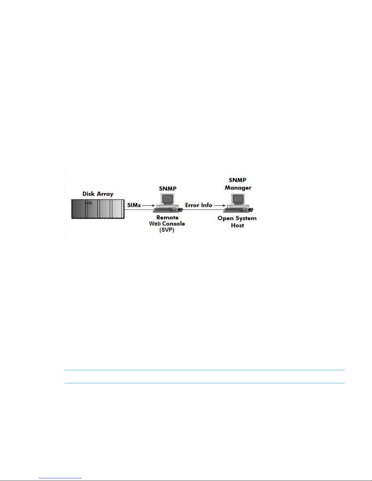
SNMP configuration
The P9000 family of disk arrays supports standard SNMP for remotely managing arrays. The
SNMP agent on the SVP performs error-reporting operations requested by the SNMP manager.
SNMP properties are usually set from the SVP but they can also be set remotely using Remote Web
Console or Command View Advanced Edition Suite Software. For specific procedures, see the
applicable user guide.
Figure 1 SNMP configuration
RAID Manager command devices
The following applies to OpenVMS, HP-UX, IBM AIX, Linux, Solaris, VMware, and Windows.
• HP StorageWorks P9000 RAID Manager Software manages HP StorageWorks P9000 Business
Copy Software or HP StorageWorks P9000 Continuous Access Synchronous Software
operations from a host server. To use RAID Manager, you must designate at least one LDEV
as a command device. This can be done with Remote Web Console or Command View
Advanced Edition Suite Software. For information about how to designate a command device,
see the applicable user guide.
• Creating scripts to configure all devices at once could save you considerable time.
The following applies to OpenVMS.
When creating a command device, HP recommends creating a LUN 0 device of 35 megabytes
(the smallest allowed). This allows you to use host-based RAID management tools available from
HP, and will allow HP support to perform some additional diagnostics.
NOTE: Storage assigned to the LUN 0 device is not accessible to OpenVMS.
SNMP configuration 13
Page 14

2 HP-UX
You and the HP service representative each play a role in installation. The HP service representative
is responsible for installing the disk array and formatting the disk devices. You are responsible for
configuring the host server for the new devices with assistance from the HP service representative.
Installation roadmap
Perform these actions to install and configure the disk array:
1. “Installing and configuring the disk array” (page 14)
• “Defining the paths” (page 15)
• “Setting the host mode and host group mode for the disk array ports” (page 15)
• “Setting the system option modes” (page 15)
• “Configuring the Fibre Channel ports” (page 16)
2. “Installing and configuring the host” (page 16)
• “Loading the operating system and software” (page 16)
• “Installing and configuring the FCAs ” (page 16)
• “Clustering and fabric zoning” (page 16)
• “Fabric zoning and LUN security for multiple operating systems” (page 17)
3. “Connecting the disk array” (page 17)
• “Verifying FCA installation” (page 17)
• “Verifying device recognition” (page 18)
4. “Configuring disk array devices” (page 19)
• “Verifying the device files and drivers” (page 20)
• “Creating the device files” (page 20)
• “Creating the physical volumes” (page 22)
• “Creating new volume groups” (page 22)
• “Creating logical volumes” (page 24)
• “Creating the file systems” (page 26)
• “Setting the I/O timeout parameter” (page 26)
• “Creating the mount directories” (page 27)
• “Mounting and verifying the file systems” (page 27)
• “Setting and verifying the auto-mount parameters” (page 28)
Installing and configuring the disk array
The HP service representative performs these tasks:
• Assembling hardware and installing software
• Loading the microcode updates
• Installing and formatting devices
After these tasks are finished, use Remote Web Console, Command View Advanced Edition, or
Array Manager to complete the remaining disk array configuration tasks. If you do not have these
programs, your HP service representative can perform these tasks for you.
14 HP-UX
Page 15

Defining the paths
Use Command View Advanced Edition or Remote Web Console to define paths between hosts
and volumes (LUNs) in the disk array.
This process is also called “LUN mapping.” In the Remote Web Console, LUN mapping includes:
• Configuring ports
• Enabling LUN security on the ports
• Creating host groups
• Assigning Fibre Channel adapter WWNs to host groups
• Mapping volumes (LDEVs) to host groups (by assigning LUNs)
In Command View Advanced Edition, LUN mapping includes:
• Configuring ports
• Creating storage groups
• Mapping volumes and WWN/host access permissions to the storage groups
For details see the HP StorageWorks P9000 Provisioning for Open Systems User Guide. Note the
LUNs and their ports, WWNs, nicknames, and LDEVs for later use in verifying host and device
configuration.
Setting the host mode and host group mode for the disk array ports
After the disk array is installed, you must set the host mode for each host group that is configured
on a disk array port to match the host OS. Set the host mode using LUN Manager in Remote Web
Console or Command View Advanced Edition. If these are not available, the HP service
representative can set the host mode using the SVP. The host mode setting for HP-UX is 08.
CAUTION: The correct host mode must be set for all new installations (newly connected ports)
to HP-UX hosts. Do not select a mode other than 08 for HP-UX. Changing a host mode after the
host has been connected is disruptive and requires the server to be rebooted.
When a new host group is added, additional host group modes (options) can be configured. The
storage administrator must verify if an additional host group mode is required for the host group.
The following host group modes (options) are available for HP-UX:
Table 1 Host group modes (options) HP-UX
CommentsDefaultFunction
Host
Group
Mode
Previously MODE280InactiveDeletion of Ghost LUN12
HP-UX 11.31 onlyInactiveTask retry ID enable33
CAUTION: Changing host group modes for ports where servers are already installed and
configured is disruptive and requires the server to be rebooted.
Setting the system option modes
The HP service representative sets system option modes based on the operating system and software
configuration of the host. In some situations, the system option modes shown in Table 2
(page 50) enable storage system behaviors that are more compatible with the requirements of a
NonStop system than the default modes. Ask your service representative if these modes apply in
your situation.
Installing and configuring the disk array 15
Page 16

Table 2 System option modes (NonStop)
Minimum microcode versionSystemOption Mode
P9500
Available from initial release142
Available from initial release454
N/A685
1
N/A724
HP also recommends setting host group mode 13 with P9000 storage systems that are connected
to HP NonStop systems.
Configuring the Fibre Channel ports
Configure the disk array Fibre Channel ports by using Command View Advanced Edition or Remote
Web Console. Select the settings for each port based on your SAN topology. Use switch zoning
if you connect different types of hosts to the array through the same switch.
Installing and configuring the host
This section explains how to install and configure Fibre Channel adapters (FCAs) that connect the
host to the disk array.
Loading the operating system and software
Follow the manufacturer's instructions to load the operating system and software onto the host.
Load all OS patches and configuration utilities supported by HP and the FCA manufacturer.
Installing and configuring the FCAs
Install and configure the Fibre Channel adapters using the FCA manufacturer's instructions.
Clustering and fabric zoning
If you plan to use clustering, install and configure the clustering software on the servers.
Clustering is the organization of multiple servers into groups. Within a cluster, each server is a
node. Multiple clusters compose a multi-cluster environment. The following example shows a
multi-cluster environment with three clusters, each containing two nodes. The nodes share access
to the disk array.
16 HP-UX
Page 17
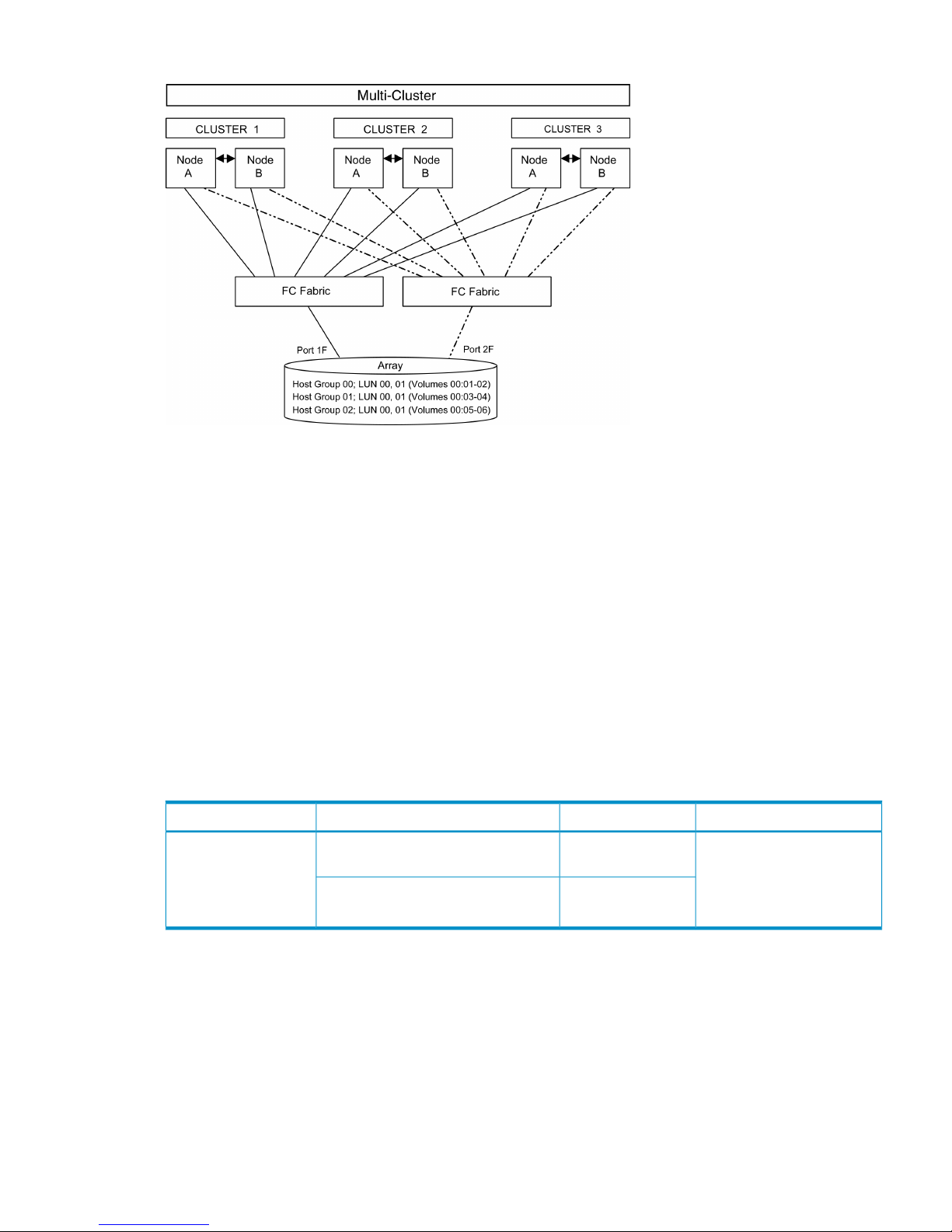
Figure 2 Multi-cluster environment (HP-UX)
Within the SAN, the clusters can be homogeneous (all the same operating system) or heterogeneous
(mixed operating systems). How you configure LUN security and fabric zoning depends on the
operating system mix and the SAN configuration.
Fabric zoning and LUN security for multiple operating systems
You can connect multiple clusters with multiple operating systems to the same switch and fabric
using appropriate zoning and LUN security as follows:
• Storage port zones can overlap if more than one operating system needs to share an array
port.
• Heterogeneous operating systems can share an array port if you set the appropriate host
group and mode. All others must connect to a dedicated array port.
• Use LUN Manager for LUN isolation when multiple hosts connect through a shared array port.
LUN Manager provides LUN security by allowing you to restrict which LUNs each host can
access.
Table 3 Fabric zoning and LUN security settings
LUN SecurityFabric ZoningOS MixEnvironment
Must be used when multiple
hosts or cluster nodes connect
through a shared port
Not requiredhomogeneous (a single OS type present
in the SAN)
Standalone SAN
(non-clustered)
Clustered SAN
Multi-Cluster SAN
Requiredheterogeneous (more than one OS type
present in the SAN)
Connecting the disk array
The HP service representative performs the following steps to connect the disk array to the host:
1. Verifying operational status of the disk array channel adapters, LDEVs, and paths.
2. Connecting the Fibre Channel cables between the disk array and the fabric switch or host.
3. Verifying the ready status of the disk array and peripherals.
Verifying FCA installation
After configuring the ports on the disk array, verify that the FCAs are installed properly.
Connecting the disk array 17
Page 18

Use the ioscan –f command, and verify that the rows shown in the example are displayed. If
these rows are not displayed, check the host adapter installation (hardware and driver installation)
or the host configuration.
Example
# ioscan –f
Class I H/W Path Driver S/W State H/W Type Description
...
fc 0 8/12 fcT1 CLAIMED INTERFACE HP Fibre ...
lan 1 8/12.5 fcT1_cntl CLAIMED INTERFACE HP Fibre ...
fcp 0 8/12.8 fcp CLAIMED INTERFACE FCP Proto...
ext bus 2 8/12.8.0.255.0 fcpdev CLAIMED INTERFACE FCP Devic...
Verifying device recognition
Verify that the HP-UX system recognizes the new devices on the disk array.
If the SCSI paths were defined after the system is powered on, you must halt and restart the system
to allow the system to recognize the new devices.
To verify device recognition:
1. Log in to the system as root.
2. Display the device data to verify that the system recognizes the newly installed devices on the
disk array. Use the ioscan –fn command to display the device data.
On a system with a large LUN configuration, HP-UX cannot build device files on all LUNs.
Enter insf –e to build all missing device files.
Example
# ioscan -fn
Class I H/W Path Driver S/W State H/W Type...
bc 6 14 ccio CLAIMED BUS_NEXUS...
fc 1 14/12 fcT1 CLAIMED INTERFACE...
lan 2 14/12.5 fcT1_cntl CLAIMED INTERFACE...
fcp 1 14/12.8 fcp CLAIMED INTERFACE...
ext_bus 6 14/12.8.0.0.0 fcpmux CLAIMED INTERFACE...
disk 4 14/12.8.0.0.0.0.0 sdisk CLAIMED DEVCE...
disk 5 14/12.8.0.0.0.0.1 sdisk CLAIMED DEVICE...
ext_bus 7 14/12.8.0.255.0 fcpdev CLAIMED INTERFACE...
target 10 14/12.8.0.255.0.0 tgt CLAIMED DEVICE...
ctl 5 14/12.8.0.255.0.0.0 sctl CLAIMED DEVICE...
In the example:
• HP OPEN-9 device: SCSI bus number = 14/12, bus instance = 6, SCSI target ID = 0,
LUN = 0.
• HP OPEN-9*2 device: SCSI bus number = 14/12, bus instance = 6, SCSI target ID =
0, LUN = 1.
• If UNKNOWN is displayed for a disk, the HP 9000 system might be configured properly.
See the HP documentation or contact HP customer support for assistance with the HP
9000 system or the HP-UX operating system.
3. Enter the device data for each disk array device in a table. See “Path worksheet” (page 115).
4. Construct the device file name for each device, using the device information, and enter the
file names in your table. Use the following formula to construct the device file name:
cxtydz
where:
• x = SCSI bus instance number
• y = SCSI target ID
18 HP-UX
Page 19

• z = LUN
• c stands for controller
• t stands for target ID
• d stands for device
The numbers x, y, and z are hexadecimal.
Table 4 Device file name example (HP-UX)
File nameLUNSCSI TIDHardware pathSCSI bus instance
number
c6t0d00614/12.6.000
c6t0d12614/12.6.100
5. Verify that the SCSI TIDs correspond to the assigned port address for all connected ports (see
mapping tables in SCSI TID map for Fibre Channel adapters (HP-UX), for values). If so, the
logical devices are recognized properly.
If the logical devices are not recognized properly:
• Check the AL-PA for each port using the LUN Manager software.
• If the same port address is set for multiple ports on the same loop (AL with HUB), all port
addresses except one changed to another value, and the relationship between AL-PA and
TID does not correspond to the mapping given in SCSI TID map for Fibre Channel adapters
(HP-UX), set a different address for each port, reboot the server, and then verify new
device recognition again.
• If unused device information remains, the TID-to-AL-PA mapping will not correspond to
the mapping given in SCSI TID map for Fibre Channel adapters (HP-UX). Renew the device
information, and then verify new device recognition again.
Configuring disk array devices
Disk arrays are configured using the same procedure for configuring any new disk on the host.
This includes the following procedures:
1. “Verifying the device files and drivers” (page 20)
2. “Creating the device files” (page 20)
3. “Creating the physical volumes” (page 22)
4. “Creating new volume groups” (page 22)
5. “Creating logical volumes” (page 24)
6. “Creating the file systems” (page 26)
7. “Setting the I/O timeout parameter” (page 26)
8. “Creating the mount directories” (page 27)
9. “Mounting and verifying the file systems” (page 27)
10. “Setting and verifying the auto-mount parameters” (page 28)
The HP-UX system uses the Logical Volume Manager (LVM) to manage the OPEN-x devices on the
disk array. The instructions in this section do not explicitly cover all LVM configuration issues. For
further information on LVM configuration, see the HP-UX user documentation.
HP System Administrator Manager (SAM) can be used instead of UNIX commands to configure
SCSI disk devices. See Reference information for the HP System Administrator Manager SAM for
further information. The newer releases of HP-UX have deprecated the SAM tool and replaced it
with the System Management Homepage (SMH) tool.
Configuring disk array devices 19
Page 20

Verifying the device files and drivers
The device files for new devices are usually created automatically during HP-UX startup. Each
device must have a block-type device file in the /dev/dsk directory and a character-type device
file in the /dev/rdsk directory.
However, some HP-compatible systems do not create the device files automatically. If verification
shows that the device files were not created, follow the instructions in “Creating the device files”
(page 20).
The following procedure verifies both types of device files:
1. Display the block-type device files in the /dev/dsk directory using the ls –l command with
the output piped to more. Verify there is one block-type device file for each disk array device.
Example
# ls –l /dev/dsk | more
Total 0
brw-r - - - - - 1 bin sys 28 0x006000 Dec 6 15:08 c6t0d0
brw-r - - - - - 1 bin sys 280 0x06100 Dec 6 15:08 c6t0d1
2. Verify that the block-type device file name for each device is correct.
3. Display the character-type device files in the /dev/rdsk directory using the ls –l command
with the output piped to more. Verify that there is one character-type device file for each disk
array device.
Example
# ls –l /dev/rdsk | more
Total 0
crw-r - - - - - 1 bin sys 177 0x006000 Dec 6 15:08 c6t0d0
crw-r - - - - - 1 bin sys 177 0x006100 Dec 6 15:08 c6t0d1
4. Use the device data table you created to verify that the character-type device file name for
each device is correct.
This task can also be accomplished with the lssf command.
5. After verifying the block-type and character-type device files, verify the HP-UX driver for the
disk array using the ioscan –fn command.
Example
# ioscan -fn
Class I H/W Path Driver S/W State H/W Type Desc
-----------------------------------------------------------bc 0 root CLAIMED BUS_NEXUS...
bc 1 8 bc CLAIMED BUS_NEXUS...
fc 0 8/12 fcT1 CLAIMED INTERFACE...
fcp 0 8/12.8 fcp CLAIMED INTERFACE...
ext_bus 2 8/12.8.0.255.0 fcpdev CLAIMED INTERFACE...
disk 3 8/12.8.8.255.0.6.0 sdisk CLAIMED DEVICE...
/dev/dsk/c2t6d0 /dev/rdsk/c2t6d0
disk 4 8/12.8.8.255.0.6.1 sdisk CLAIMED DEVICE...
/dev/dsk/c2t6d1 /dev/rdsk/c2t6d1
disk 5 8/12.8.8.255.0.8.0 sdisk CLAIMED DEVICE...
/dev/dsk/c2t8d0 /dev/rdsk/c2t8d0
Creating the device files
If the device files were not created automatically when the system was restarted, use the insf
–e command in the /dev directory to create the device files. After this command is executed,
20 HP-UX
Page 21

repeat the procedures in “Verifying device recognition” (page 18) to verify new device recognition
and the device files and driver.
Example
# insf -e
insf: Installing special files for mux2 instance 0 address 8/0/0
: : : :
: : : :
#
Failure of the insf –e command indicates a SAN problem.
If the device files for the new disk array devices cannot be created automatically, you must create
the device files manually using the mknodcommand as follows:
1. Retrieve the device information you recorded earlier.
2. Construct the device file name for each device, using the device information, and enter the
file names in your table. Use the following formula to construct the device file name:
cxtydz
where:
• x = SCSI bus instance number
• y = SCSI target ID
• z = LUN
• c stands for controller
• t stands for target ID
• d stands for device
The numbers x, y, and z are hexadecimal.
3. Construct the minor number for each device, using the device information, and enter the file
names in your table. Use the following formula to construct the minor number:
0xxxyz00 where
xx = SCSI bus instance number, y = SCSI target ID, and z = LUN.
4. Display the driver information for the system using the lsdev command.
Example
# lsdev
Character Block Driver Class
: : : :
188 31 sdisk disk
#
5. Enter the major numbers for the device drivers into the table. You should now have all required
device and driver information in the table.
Configuring disk array devices 21
Page 22

6. Create the device files for all disk array devices (SCSI disk and multiplatform devices) using
the mknodcommand. Create the block-type device files in the /dev/dsk directory and the
character-type device files in the /dev/rdsk directory.
Example
# cd /dev/dsk Go to /dev/dsk directory.
# mknod /dev/dsk/c2t6d0 b 31 0x026000 Create block-type file.
File name, b=block-type,
31=major #, 0x026000= minor #
# cd /dev/rdsk Go to /dev/rdsk directory.
# mknod /dev/rdsk/c2t6d0 c 188 0x026000 Create character-type file.
File name, c=character-type,
177=major #, 0x026000=minor #
:
#
The character-type device file is required for volumes used as raw devices (for example,
3390-3A/B/C). The block-type device file is not required for volumes used as raw devices.
If you need to delete a device file, use the rm –i command.
Table 5 Device information example (HP-UX)
Major
no.
block
files
Major
no.
char.
files
Minor no.Dev fileLUNTIDDev typeDriverHW pathDiskInstBus
311880x026000c2t6d006OPEN-9sdisk8/12.8.8.255.0.6.03028/12
311880x026100c2t6d116OPEN-9sdisk8/12.8.8.255.0.6.14028/12
311880x028000c2t8d0083390-3Bsdisk8/12.8.8.255.0.8.05028/12
Creating the physical volumes
A physical volume must be created for each new SCSI disk device.
To create the physical volumes:
1. Use the pvcreate command to create the physical volumes with the character-type device
file as the argument. Specify the /dev/rdsk directory.
Example
# pvcreate /dev/rdsk/c6t0d0
Physical volume "/dev/rdsk/c6t0d0" has been successfully created.
:
# pvcreate /dev/rdsk/c6t0d1
Physical volume "/dev/rdsk/c6t0d1" has been successfully created.
Do not use the –f option with the pvcreate command. This option creates a new physical
volume forcibly and overwrites the existing volume. If you accidentally enter the character-type
device file for an existing volume, you will lose the data on that volume.
2. Repeat step 1 for each OPEN-x device on the disk array.
Creating new volume groups
You must create new volume groups for the new physical volumes. If desired, you can also add
any of the volumes on the disk array to existing volume groups using the vgextend command.
22 HP-UX
Page 23

The physical volumes that make up one volume group can be located either in the same disk array
or in other disk arrays.
To allow more volume groups to be created, use SAM to modify the HP-UX system kernel
configuration. See Reference information for the HP System Administrator Manager SAM for details.
The newer releases of HP-UX have deprecated the SAM tool and replaced it with the System
Management Homepage (SMH) tool.
To create volume groups:
1. Use the vgdisplay command to display the existing volume groups.
2. Choose a unique name for the new volume group (for example: vg06).
3. Create the directory for the new volume group.
Example
# mkdir /dev/vg06
4. Use the ls –l command (with the output piped to grep to display only the files containing
“group”) to display the minor numbers for the existing group files.
Example
# ls –1 /dev/vg* | grep group
crw-rw-rw 1 root root 64 0x0000000 Nov7 08:13 group
:
5. Choose a unique minor number for the new group file in sequential order (for example, when
existing volume groups are vg00-vg05 and the next group name is vg06, use minor number
06 for the vg06 group file).
The minor numbers are hexadecimal (for example, the 10th minor number is 0x0a0000).
6. Use mknod to create the group file for the new directory. Specify the volume group name,
major number, and minor number. The major number for all group files is 64.
Example
In this example: group name = vg06, major number of group file = 64, minor number of
existing group file = 06 (which must be unique for each volume group), and c = character.
# mknod /dev/vg06/group c 64 0x060000
:
7. Create the volume group.
To allocate more than one physical volume to the new volume group, add the other physical
volumes, separated by a space.
Example
# vgcreate /dev/vg06 /dev/dsk/c6t0d0
Volume group "/dev/vg06" has been successfully created.
Volume group configuration for /dev/vg06 has been saved in
/etc/1vmconf/vg06.conf.
For Logical Unit Size Expansion (LUSE) volumes that contain more than 17 OPEN-8/9 LDEVs
or more than 7043 MB (OPEN-8/9*n-CVS), use the –s and –e physical extent (PE) parameters
of the vgcreate command. See LUSE device parameters.
If you need to delete a volume group, use the vgremove command (for example, vgremove
/dev/vgnn). If the vgremove command does not work because the volume group is not
active, use the vgexport command (for example, vgexport /dev/vgnn).
8. Use the vgdisplay command to verify that the new directory was created.
Configuring disk array devices 23
Page 24

9. Use vgdisplay –v to verify that the volume group was created correctly. The –v option
displays the detailed volume group information.
Example
# vgdisplay –v /dev/vg06
- - - Volume groups - - VG Name /dev/vg06
VG Write Access read/write
VG Status available
Max LV 255
Cur LV 0
Open LV 0
Max PV 16
Cur PV 1
Act PV 1
Max PE per PV 1016
VGDA 2
PE Size (Mbytes) 4
Total PE 586
Alloc PE 0
Free PE 586
Total PVG 0
- - Physical Volumes - - PV Name /dev/dsk/c6t0d0
PV Status available
Total PE 586
Free PE 586
Creating logical volumes
Use these commands for logical volume configuration:
• lvremove
Deletes a logical volume. Any file system attached to the logical volume must be unmounted
before executing the lvremove command.
Example
lvremove /dev/vgnn/lvolx
• lvextend
Increases the size of an existing logical volume.
Example
lvextend –L size /dev/vgnn/lvolx
• lvreduce
Decreases the size of an existing logical volume. Any file system attached to the logical volume
must be unmounted before executing the lvreduce command.
Example
lvreduce –L size /dev/vgnn/lvolx
CAUTION: Data within the file system can be lost after execution of lvreduce.
Create logical volumes after you create volume groups. A logical volume must be created for each
new SCSI disk device.
24 HP-UX
Page 25

To create logical volumes:
1. Use the lvcreate –L command to create a logical volume.
Specify the volume size (in megabytes) and the volume group for the new logical volume.
HP-UX assigns the logical volume numbers automatically (lvol1, lvol2, lvol3). Use the following
capacity values for the size parameter:
OPEN-K = 1740
OPEN-3 = 2344
OPEN-8 = 7004
OPEN-9 = 7004
OPEN-E = 13888
OPEN-L = 34756
OPEN-V = 61432
To calculate S1 for CVS, LUSE, and CVS LUSE volumes, first use the vgdisplay command
to display the physical extent size (PE Size) and usable number of physical extents (Free PE)
for the volume. Calculate the maximum size value (in MB) as follows:
S1 = (PE Size) × (Free PE)
Logical volumes can span multiple physical volumes. Use the diskinfo command for extended
LUNs.
2. Create an OPEN-3 logical volume the size of the physical volume, using 2344 for the size
parameter. An OPEN-9 volume uses 7040 for the size parameter to create a logical volume
the size of the physical volume.
Example
# lvcreate –L 2344 /dev/vg06
Logical volume "/dev/vg06/lvol1" has been successfully created with
character device "/dev/vg06/rlvol1".
Logical volume "/dev/vg06/lvol1" has been successfully extended.
Volume Group configuration for /dev/vg06 has been saved in
/etc/1vmconf/vg06.conf.
3. Use the lvdisplay command to verify that the logical volume was created correctly.
Example
# lvdisplay /dev/vg06/lvol1
- - - Logical volume - - LV Name /dev/vg06/lvol1
VG Name /dev/vg06
LV Permission read/write
LV Status available/syncd
Mirror copies 0
Consistency Recovery MWC
Schedule parallel
LV Size (Mbytes) 2344
Current LE 586
Allocated PE 586
Stripes 0
Stripe Size (Kbytes) 0
Bad block on
Allocation strict
4. Repeat steps 1–3 for each logical volume to be created.
You can create only one logical volume at a time. However, you can verify multiple logical
volumes at a time.
Configuring disk array devices 25
Page 26

Creating the file systems
Create the file system for each new logical volume on the disk array. The default file system types
are:
• HP-UX OS version 10.20 = hfs or vxfs, depending on entry in the /etc/defaults/fs
file.
• HP-UX OS version 11.0 = vxfs
• HP-UX OS version 11.i = vxfs
To create file systems:
1. Use the newfs command to create the file system using the logical volume as the argument.
Example 1
# newfs /dev/vg06/rlvol1
newfs: /etc/default/fs determine the file system type
mkfs (hfs): Warning -272 sectors in the last cylinder are not
allocated.
mkfs (hfs): /dev/vg06/rlvol1 - 2400256 sectors in 3847 cylinders
of 16 tracks,
2547.9MB in 241 cyl groups (16 c/g, 10.22Mb/g, 1600 ig/g)
Super block backups (for fsck -b) at:
16, 10040, 20064, 30038, 40112, 50136, 60160, 70184, 80208, 90232, ...
2396176
Example 2
# newfs /dev/vg06/rlvol1 create file system
newfs: / etc/default/fs determine the file system type
mkfs (hfs): ...
:
7188496, 7198520, 7208544
#
Example 3
# newfs -F vxfs /dev/vg06/rlvol1 Specify file system type
:
# newfs -F hfs /dev/vg06/rlvol2
2. Repeat step 1 for each logical volume on the disk array.
Setting the I/O timeout parameter
Set the I/O timeout value for each disk device to 60 seconds.
1. Verify the current I/O timeout value using the pvdisplay command:
Example
# pvdisplay /dev/dsk/c0t6d0
- - - Physical volumes - - PV Name /dev/dsk/c0t6d0
VG Name /dev/vg06
PV Status available
Allocatable yes
VGDA 2
Cur LV 1
PE Size (Mbytes) 4
Total PE 586
Free PE 0
Allocated PE 586 [OPEN-9]
Stale PE 0
IO Timeout (Seconds) default [I/O timeout value]
2. If the I/O timeout value is not 60, change the value to 60 using the pvchange -t command:
26 HP-UX
Page 27

Example
# pvchange -t 60 /dev/dsk/c0t6d0
Physical volume "/dev/dsk/c0t6d0" has been successfully changed.
Volume Group configuration for /dev/vg06 has been saved in
/etc/lvmconf/vg06.conf.
3. Verify that the new I/O timeout value is 60 seconds using the pvdisplay command:
Example
# pvdisplay /dev/dsk/c0t6d0
--- Physical volumes --PV Name /dev/dsk/c0t6d0
VG Name /dev/vg06
PV Status available
:
Stale PE 0
IO Timeout (Seconds) 60 [New I/O timeout value]
4. Repeat steps 1–3 for each new disk connected to the system.
Creating the mount directories
Create a mount directory for each logical volume. Choose a unique name for each mount directory
that identifies the logical volume.
To create a mount directory for each logical volume:
1. Use mkdir with the new mount directory name as the argument to create the mount directory.
Example
# mkdir /AHPMD-LU00
2. Use the ls –x command to verify the new mount directory.
Example
The following example shows the root directory as the location for the mount directories.
# ls -x
AHPMD-LU00 bin dev device etc export
floppy home hstsboof kadb kernel lib
3. Repeat steps 1–2 for each logical volume on the disk array.
Mounting and verifying the file systems
After the mount directories have been created, mount and verify the file system for each logical
volume.
To mount and verify the file systems:
1. Use mount to mount the file system for the volume.
Example
# mount /dev/vg06/lvol1 /AHPMD-LU00
2. Repeat step 1 for each logical volume on the disk array.
If you need to unmount a file system, use the unmount command.
3. Use the bdf command to verify that the file systems are correct. The capacity is listed under
Kbytes.
Example
# bdf
Filesystem Kbytes used avail %used Mounted on
Configuring disk array devices 27
Page 28

/ldev/vg00/lvol1 59797 59364 0 100% /
:
/ldev/vg06/lvol1 2348177 9 2113350 0% /AHPMD-LU00
4. As a final verification, perform some basic UNIX operations (for example file creation, copying,
and deletion) on each logical device to make sure that the devices on the disk array are fully
operational.
Example
#cd /AHPMD-LU00
#cp /bin/vi /AHPMD-LU00/vi.back1
#ls -l
drwxr-xr-t 2 root root 8192 Mar 15 11:35 lost+found
-rwxr-xr-x 1 root sys 217088 Mar 15 11:41 vi.back1
#cp vi.back1 vi.back2
#ls -l drwxr-xr-t 2 root root 8192 Mar 15 11:35 lost+found
-rwxr-xr-x 1 root sys 217088 Mar 15 11:41 vi.back1
-rwxr-xr-x 1 root sys 217088 Mar 15 11:52 vi.back2
Setting and verifying the auto-mount parameters
Set up and verify the auto-mount parameters for each new volume. The /etc/checklist file
(which can also be called the /etc/fstab file) contains the auto-mount parameters for the logical
volumes.
To set up and verify the auto-mount parameters:
1. Edit the /etc/checklist (/etc/fstab) file to add a line for each OPEN-x device on the
disk array. This example and the following table show the auto-mount parameters.
Example
#cp -ip /etc/checklist /etc/checklist.standard
#vi /etc/checklist
/dev/vg00/lvol1 / hfs rw 0 1 # root
/dev/vg00/lvol2 swap ignore rw 0 0 # primary swap
:
/dev/vg06/lvol1 /AHPMD-LU00 hfs defaults 0 2 # AHPMD-LU00
/dev/vg06/lvol2 /AHPMD-LU01 hfs defaults 0 2 # AHPMD-LU01
P1 P2 P3 P4 P5 P6 P7
Table 6 Auto-mount parameters (HP-UX)
EnterNameParameter
Block-type device file nameDevice to mountP1
Mount directory nameMount pointP2
Type of file system (for example, hfs, vxfs)File systemP3
“defaults” or other appropriate mount optionsMount optionsP4
0EnhanceP5
Order for performing file system checksFile system check (fsck pass)P6
Comment statementCommentsP7
2. Reboot the system.
28 HP-UX
Page 29

3. Use the bdf command to verify the file system again.
Configuring disk array devices 29
Page 30

3 Windows
You and the HP service representative each play a role in installation. The HP service representative
is responsible for installing the disk array and formatting the disk devices. You are responsible for
configuring the host server for the new devices with assistance from the HP service representative.
Installation roadmap
Perform these actions to install and configure the disk array:
1. “Installing and configuring the disk array” (page 30)
• “Defining the paths” (page 30)
• “Setting the host mode and host group mode for the disk array ports” (page 31)
• “Setting the system option modes” (page 32)
• “Configuring the Fibre Channel ports” (page 32)
2. “Installing and configuring the host” (page 32)
• “Loading the operating system and software” (page 32)
• “Installing and configuring the FCAs ” (page 32)
• “Fabric zoning and LUN security” (page 33)
3. “Connecting the disk array” (page 33)
• “Verifying the host recognizes array devices” (page 34)
4. “Configuring disk devices” (page 34)
• “Writing signatures” (page 34)
• “Creating and formatting disk partitions” (page 35)
• “Verifying file system operations ” (page 35)
Installing and configuring the disk array
The HP service representative performs these tasks:
• Assembling hardware and installing software
• Loading the microcode updates
• Installing and formatting devices
After these tasks are finished, use Remote Web Console, Command View Advanced Edition, or
Array Manager to complete the remaining disk array configuration tasks. If you do not have these
programs, your HP service representative can perform these tasks for you.
Defining the paths
Use Remote Web Console or Command View Advanced Edition to define paths (LUNs) between
hosts and volumes in the disk array.
This process is also called “LUN mapping.” In Remote Web Console, LUN mapping includes:
• Configuring ports
• Enabling LUN security on the ports
• Creating host groups
• Assigning Fibre Channel adapter WWNs to host groups
• Mapping volumes (LDEVs) to host groups (by assigning LUNs)
30 Windows
Page 31

In Command View Advanced Edition, LUN mapping includes:
• Configuring ports
• Creating storage groups
• Mapping volumes and WWN/host access permissions to the storage groups
For more information about LUN mapping, see the HP StorageWorks P9000 Provisioning for Open
Systems User Guide or Remote Web Console online help. Note the LUNs and their ports, WWNs,
nicknames, and LDEVs for later use in verifying host and device configuration.
IMPORTANT: A LUN assigned a number greater than FF is outside the accepted range of numbers
for a Windows server (00 to FE) and will not be recognized by the server or be visible for use.
Windows 2000: A LUN 0 must be created to discover more than LUNs 0 to 7.
Setting the host mode and host group mode for the disk array ports
After the disk array is installed, set the host mode for each host group that is configured on a disk
array port to match the host OS. Set the host mode using LUN Manager in Remote Web Console
or Command View Advanced Edition. If these are not available, the HP service representative can
set the host mode using the SVP.
The available host mode settings are as follows:
Table 7 Host mode settings (Windows)
DescriptionHost mode
HP recommended. For use with LUSE volumes when online LUN
expansion is required or might be required in the future.
2C (available on some array
models)
HP recommended. Use if future online LUN expansion is not
required or planned.
0C
Table 8 Volume names for host mode setting (Windows)
Volume name as seen on hostVolume on P9000 array (examples)
host mode = 2Chost mode = 0C
OPEN-EOPEN-EOPEN-E
OPEN-9OPEN-9OPEN-9
OPEN-9OPEN-9*2OPEN-9*2
OPEN-9-CVSOPEN-9*3-CVSOPEN-9*3-CVS
CAUTION: The correct host mode must be set for all new installations (newly connected ports)
to Windows hosts. Do not select a mode other than 2C or 0C. Changing a host mode after the
host is connected is disruptive and requires a server reboot.
When a new host group is added, additional host group modes (options) can be configured. The
storage administrator must verify if an additional host group mode is required for the host group.
The following host group modes (options) are available for Windows:
Installing and configuring the disk array 31
Page 32

Table 9 Host group modes (options) Windows
DefaultFunctionHost Group
Mode
InactiveParameter Setting Failure for TPRLO
When using the Emulex FCA in the Windows environment, the
parameter setting for TPRLO failed. After receiving TPRLO and
FCP_CMD, respectively. PRLO will respond when HostMode=0x0C/
0x2C and HostModeOption=0x06. (MAIN Ver.50-03-14-00/00
and later)
6
InactiveSIM report at link failure.
Select HMO 13 when you want SIM notification when the number
of link failures detected between ports exceeds the threshold.
13
InactiveV-Vol expansion.
Select HMO 40 when all of the following conditions are satisfied:
• The host mode 0C Windows or 2C Windows Extension is used.
• You want to automate recognition of the DP-VOL capacity after
increasing the DP-VOL capacity.
40
CAUTION: Changing host group modes for ports where servers are already installed and
configured is disruptive and requires the server to be rebooted.
Setting the system option modes
The HP service representative sets the system option mode(s) based on the operating system and
software configuration of the host. Notify your HP representative if you install storage agnostic
software (such as backup or cluster software) that might require specific settings.
Configuring the Fibre Channel ports
Configure the disk array Fibre Channel ports by using Command View Advanced Edition or Remote
Web Console. Select the settings for each port based on your SAN topology. Use switch zoning
if you connect different types of hosts to the array through the same switch.
Installing and configuring the host
This section explains how to install and configure Fibre Channel adapters (FCAs) that connect the
host to the disk array.
Loading the operating system and software
Follow the manufacturer's instructions to load the operating system and software onto the host.
Load all OS patches and configuration utilities supported by HP and the FCA manufacturer.
Installing and configuring the FCAs
Install and configure the Fibre Channel adapter using the FCA manufacturer's instructions.
HP supplies driver, firmware, and BIOS downloads for commonly available FCAs. These downloads
contain FCA settings that are tested and approved by HP. To obtain a download, log onto the HP
website at www.hp.com and search for the model name or number of your FCA. Download the
file, and follow the installation instructions in the “readme” or documentation file supplied with
each download.
Contact your HP representative for current information on compatible FCAs.
32 Windows
Page 33

Fabric zoning and LUN security
By using appropriate zoning and LUN security, you can connect various servers with various
operating systems to the same switch and fabric with the following restrictions:
• Storage port zones can overlap if more than one operating system needs to share an array
port.
• Heterogeneous operating systems can share an array port if you set the appropriate host
group and mode. All others must connect to a dedicated array port.
• Use LUN Manager for LUN isolation when multiple hosts connect through a shared array port.
LUN Manager provides LUN security by allowing you to restrict which LUNs each host can
access.
• QLogic and Emulex FCAs must be in separate zones (a QLogic zone and an Emulex zone)
whether the FCAs are in the same or separate servers.
• If booting over the SAN, within a server, the booting FCAs must be from the same vendor.
Additional data storage FCAs can be from a different vendor.
Table 10 Fabric zoning and LUN security settings (Windows)
LUN securityFabric zoningOS mixEnvironment
Must be used when
multiple hosts or cluster
nodes connect through
a shared port
Not requiredhomogeneous (a
single OS type present
in the SAN)
Standalone SAN
(non-clustered)
Clustered SAN
Multi-Cluster SAN
Requiredheterogeneous (more
than one OS type
present in the SAN)
• If you plan to use clustering, install and configure the clustering software on the servers.
Clustering is the organization of multiple servers into groups. Within a cluster, each server is
a node. Multiple clusters compose a multi-cluster environment. The following example shows
a multi-cluster environment with three clusters, each containing two nodes. The nodes share
access to the disk array.
Figure 3 Multi-cluster environment (Windows)
Connecting the disk array
The HP service representative performs the following steps to connect the disk array to the host:
Connecting the disk array 33
Page 34

1. Verifying operational status of the disk array channel adapters, LDEVs, and paths.
2. Connecting the Fibre Channel cables between the disk array and the fabric switch or host.
3. Verifying the ready status of the disk array and peripherals.
Verifying the host recognizes array devices
1. Log into the host as an administrator.
2. Right-click My Computer , and then click Manage.
3. Click Device Manager.
4. Click SCSI and then RAID Controllers.
5. Click the Fibre Channel adapter, and verify all devices are displayed.
6. Click each device, click Properties, and then click Settings.
7. Record the device information using the worksheet in “Worksheet” (page 115).
Configuring disk devices
Disk devices are configured using the following procedures:
• “Writing signatures” (page 34)
• “Creating and formatting disk partitions” (page 35)
• “Verifying file system operations ” (page 35)
NOTE: You must use GPT for disk devices greater than 2TB.
Writing signatures
1. Right-click My Computer and then click Manage.
2. Click Disk Management. A message notifies you that disks have been added.
3. Click OK to update the system configuration and start the Write Signature wizard.
4. For each new disk, click OK to write a signature, or click No to prevent writing a signature.
5. When you have performed this process for all new disks, the Disk Management main window
opens and displays the added disks.
34 Windows
Page 35

Creating and formatting disk partitions
Dynamic Disk is supported with no restrictions for a disk array connected to a Windows
2000/2003/2008 system. For more information, see Microsoft's online help.
CAUTION: Do not partition or create a file system on a device that will be used as a raw device
(for example, some database applications use raw devices.)
1. In the Disk Management main window, select the unallocated area for the SCSI disk you want
to partition.
2. Click the Action menu, and then click Create Partition to launch the New Partition Wizard.
Follow the Partition Wizard to create and format partitions and assign drive letters. Format
partitions with the following settings and format options.
File System: NTFS (enables Windows to write to the disk).
Allocation unit size: Default. Do not change this entry.
Volume label: Enter a volume label, or leave this field blank for no label.
Format Options: Click Perform a Quick Format to decrease the time required to format the
partition. Click Enable file and folder compression only if you want to enable compression.
3. Verify the Disk Management main window displays the correct file system (NTFS) for the
formatted partition. “Healthy” indicates the partition has been created and formatted
successfully.
4. Repeat this procedure for each new disk device.
5. Exit Disk Management, clicking Yes to save your changes.
Verifying file system operations
1. Open My Computer and check that the new disks are present.
2. Right-click each disk to view Properties and verify the properties are correct (label, type,
capacity, and file system).
3. Copy a file from an existing drive to each new drive to verify the new drives are working,
and then delete the copies.
Configuring disk devices 35
Page 36

4 Novell NetWare
You and the HP service representative each play a role in installation. The HP service representative
is responsible for installing the disk array and formatting the disk devices. You are responsible for
configuring the host server for the new devices with assistance from the HP service representative.
Installation roadmap
Perform these actions to install and configure the disk array:
1. “Installing and configuring the disk array” (page 36)
• “Defining the paths” (page 36)
• “Setting the host mode and host group mode for the disk array ports” (page 37)
• “Configuring the Fibre Channel ports” (page 37)
2. “Installing and configuring the host” (page 37)
• “Loading the operating system and software” (page 37)
• “Installing and configuring the FCAs ” (page 37)
• “Configuring NetWare client” (page 37)
• “Configuring NetWare ConsoleOne” (page 38)
• “Clustering and fabric zoning” (page 38)
• “Fabric zoning and LUN security for multiple operating systems” (page 39)
3. “Connecting the disk array” (page 39)
• “Verifying new device recognition” (page 39)
4. “Configuring disk devices” (page 40)
• “Creating the disk partitions” (page 40)
• “Assigning the new devices to volumes” (page 42)
• “Mounting the new volumes” (page 43)
• “Verifying client operations” (page 43)
Installing and configuring the disk array
The HP service representative performs these tasks:
• Assembling hardware and installing software
• Loading the microcode updates
• Installing and formatting devices
After these tasks are finished, use Remote Web Console, Command View Advanced Edition, or
Array Manager to complete the remaining disk array configuration tasks. If you do not have these
programs, your HP service representative can perform these tasks for you.
Defining the paths
Use Command View Advanced Edition or Remote Web Console to define paths between hosts
and volumes (LUNs) in the disk array.
This process is also called “LUN mapping.” In the Remote Web Console, LUN mapping includes:
• Configuring ports
• Enabling LUN security on the ports
36 Novell NetWare
Page 37

• Creating host groups
• Assigning Fibre Channel adapter WWNs to host groups
• Mapping volumes (LDEVs) to host groups (by assigning LUNs)
In Command View Advanced Edition, LUN mapping includes:
• Configuring ports
• Creating storage groups
• Mapping volumes and WWN/host access permissions to the storage groups
For details see the HP StorageWorks P9000 Provisioning for Open Systems User Guide. Note the
LUNs and their ports, WWNs, nicknames, and LDEVs for later use in verifying host and device
configuration.
Setting the host mode and host group mode for the disk array ports
After the disk array is installed, you must set the host mode for each host group that is configured
on a disk array port to match the host OS. Set the host mode using LUN Manager in Remote Web
Console or Command View Advanced Edition. If these are not available, the HP service
representative can set the host mode using the SVP. The host mode setting for Novell NetWare is
0A.
CAUTION: The correct host mode must be set for all new installations (newly connected ports)
to Novell NetWare hosts. Do not select a mode other than 0A for Novell NetWare. The host modes
must be set for certain middleware environments (for example, Novell High Availability Server,
NHAS, System Fault Tolerance, SFT III). Changing a host mode after the host has been connected
is disruptive and requires the server to be rebooted.
When a new host group is added, additional host group modes (host mode options) can be
configured. The storage administrator must verify if an additional host group mode is required for
the host group.
CAUTION: Changing host group modes for ports where servers are already installed and
configured is disruptive and requires the server to be rebooted.
Configuring the Fibre Channel ports
Configure the disk array Fibre Channel ports by using Command View Advanced Edition or Remote
Web Console. Select the settings for each port based on your SAN topology. Use switch zoning
if you connect different types of hosts to the array through the same switch.
Installing and configuring the host
This section explains how to install and configure Fibre Channel adapters (FCAs) that connect the
host to the disk array.
Loading the operating system and software
Follow the manufacturer's instructions to load the operating system and software onto the host.
Load all OS patches and configuration utilities supported by HP and the FCA manufacturer.
Installing and configuring the FCAs
Install and configure the Fibre Channel adapters using the FCA manufacturer's instructions.
Configuring NetWare client
NetWare 6.x
Installing and configuring the host 37
Page 38

NetWare Client software is required for the client system. After installing the software on the
NetWare server, follow these steps:
1. Open the Novell Client Configuration dialog and click the Advanced Settings tab.
2. Change the following parameters:
Give up on Requests to Sas: 180
Net Status Busy Timeout: 90
Configuring NetWare ConsoleOne
NetWare 6.x
Novell NetWare v6.x requires a tool called ConsoleOne to work in a storage environment.
ConsoleOne is a free Java utility used to manage network resources. Configure ConsoleOne as
follows:
1. Ensure NetWare Client software is already installed.
2. Install ConsoleOne on the NetWare 6.x server.
3. From the NetWare Client, run ConsoleOne:
z:public/mgmt/consoleOne/1.2/bin/ConsoleOne
4. Right-click the Server icon, and select Disk Management Devices.
5. Scroll left to the Media tab.
6. Click Partitions, New, and select a device.
7. Click Create, click NSS pools, click New, and name the pool. The pool name and volume
name can be the same.
8. Click Create, click NSS Logical Volume, select New, name the volume, then select the pool.
9. Select Allow volume quota to grow to pool size.
10. Leave the default settings on the next page and click Finish.
Clustering and fabric zoning
If you plan to use clustering, install and configure the clustering software on the servers.
Clustering is the organization of multiple servers into groups. Within a cluster, each server is a
node. Multiple clusters compose a multi-cluster environment. The following example shows a
multi-cluster environment with three clusters, each containing two nodes. The nodes share access
to the disk array.
38 Novell NetWare
Page 39

Figure 4 Multi-cluster environment (Novell NetWare)
Within the SAN, the clusters must be homogeneous (all the same operating system). Heterogeneous
(mixed operating systems) clusters are not allowed. How you configure LUN security and fabric
zoning depends on the SAN configuration.
Fabric zoning and LUN security for multiple operating systems
You can connect multiple clusters with multiple operating systems to the same switch and fabric
using appropriate zoning and LUN security as follows:
• Storage port zones can overlap if more than one operating system needs to share an array
port.
• Heterogeneous operating systems can share an array port if you set the appropriate host
group and mode. All others must connect to a dedicated array port.
• Use LUN Manager for LUN isolation when multiple hosts connect through a shared array port.
LUN Manager provides LUN security by allowing you to restrict which LUNs each host can
access.
Table 11 Fabric zoning and LUN security settings (Novell NetWare)
LUN SecurityFabric ZoningOS MixEnvironment
Must be used when multiple
hosts or cluster nodes connect
through a shared port
Not requiredhomogeneous (a single OS type present
in the SAN)
Standalone SAN
(non-clustered)
Clustered SAN
Multi-Cluster SAN
Requiredheterogeneous (more than one OS type
present in the SAN)
Connecting the disk array
The HP service representative performs the following steps to connect the disk array to the host:
1. Verifying operational status of the disk array channel adapters, LDEVs, and paths.
2. Connecting the Fibre Channel cables between the disk array and the fabric switch or host.
3. Verifying the ready status of the disk array and peripherals.
Verifying new device recognition
To verify that the NetWare system recognizes the new disk array devices:
Connecting the disk array 39
Page 40

1. In the NetWare directory, enter SERVER to get to the server console.
2. At the server console, enter LIST DEVICES to display all devices. Use the Pause key as
needed. The device number (for example, 0x000B) and device type are displayed for each
device:
Example
NetWare prompt> LIST DEVICES
1. 0x000B: [V6E0-A2-D7D:0] HP OPEN-3 rev:0111
2. 0x000C: [V6E0-A2-D7D:1] HP OPEN-3 rev:0111
:
:
3. Record the device number for each new device on the worksheet in “Path worksheet” (page 115).
This information will be useful later during disk partitioning and volume creation.
4. Verify that all new disk devices are listed.
Configuring disk devices
Configure the disks in the disk array using the same procedure for configuring any new disk on
the host. This includes the following procedures:
1. “Creating the disk partitions” (page 40)
2. “Assigning the new devices to volumes” (page 42)
3. “Mounting the new volumes” (page 43)
4. “Verifying client operations” (page 43)
Creating scripts to configure all devices at once can save you considerable time.
Creating the disk partitions
Before you create the disk partitions, consult the Novell documentation for confirmation about the
type of partition that is available with your operating system version.
NetWare 5.x
1. At the server console enter “LOAD NWCONFIG” to load the Configuration Options module.
2. On the Configuration Options screen, click Standard disk options and press Enter to access
the NetWare disk options.
3. On the Available Disk Options screen, select Modify disk partitions and Hot Fix and press
Enter.
4. The Available Disk Drives screen lists the devices by device number. Record the device numbers.
On the Available Disk Drives screen, select the device to partition, and then press Enter.
5. If the partition table has already been initialized, skip this step. If the partition table has not
been initialized, the partition table message is displayed. Press Enter to confirm the message.
When the Initialize the partition table? message appears, select Yes and press Enter to initialize
the partition table.
6. On the Disk Partition Options screen, select Create NetWare disk partition, and press Enter.
7. You are now prompted to create the partition either automatically or manually. Select the
desired option, and press Enter.
If you select automatic partitioning, NetWare will create the disk partition and hot fix area
using the available disk space (the hot fix area will be approximately two percent of the
partition size). If you select manual partitioning, enter a partition size and hot fix area.
8. On the Disk Partition Information screen, verify (or enter) the partition size and hot fix data
area size, and press F10 to save the changes. The Disk Partition Options screen appears.
9. Select Create NetWare disk partition again, and press Enter.
10. When the Create NetWare Partition? message appears, click Yes and press Enter to create
the specified disk partition on the selected device.
40 Novell NetWare
Page 41

11. Press Esc until you are returned to the Available Devices screen. Repeat Step 4–Step 10 to
create the disk partition on each new OPEN-x and LUSE device.
12. When you are finished creating disk partitions, return to the Available Disk Options screen,
click Return to previous menu and press Enter.
NetWare 6.0
1. Start ConsoleOne on the Windows server.
2. Select and right-click the targeted server, and then click Properties.
3. Select the Media tab, click Devices, and then initialize the new devices.
4. Click the Partitions option on the Media tab, select the desired device, and then select New....
The Create a new partition screen appears.
5. On the Create a new partition screen, select the desired device, select NSS in the Type box,
and click OK.
6. Enter the partition size in bytes (B), kilobytes (KB), megabytes (MB), or gigabytes (GB), and
then click OK.
7. To reserve space for the Hot Fix error correction feature, select Hot Fix and enter the amount
of space or percentage you want to reserve.
Mirrored partitions must be compatible in data area size. This means the new partition must
be at least the same size or slightly larger than the other partitions in the group. The physical
size (combined data and Hot Fix size) of the partition must be at least 100 KB larger, but no
more than 120 MB larger than the data size of the existing partitions in the mirror group.
8. To mirror the partition, select Mirror and select one of the following options:
• Create New Mirror. This option means you are making the partition capable of being
part of a mirror group. You do not actually create the group until you add another mirrored
partition to the partition you are creating.
• Existing Mirror Group. (If you select this option, also select the ID of the mirrored partition.)
This shows a list of existing mirror groups that are compatible in data area size. This
option lets you add this new partition to one of the mirror groups in the list.
9. Select NSSPools on the Media tab, and select New….
The Create a New Pool screen appears.
10. On the Create a New Pool screen, enter the name for the new pool, and click Next.
11. Select the disk to be included in the pool, and click Next.
12. On the Create Pool – Attribute Information screen, check Activate on Creation to make the
new pool active, and then click Finish.
13. Select a label for the partition (optional).
14. Click OK.
NetWare 6.5
1. Enter NSSMU at the server console.
2. In the main menu, select Partitions.
3. Press Insert, then select a device where you want to create a partition.
4. Select NSS as the partition type.
5. Enter the size of the partition in bytes (B), kilobytes (KB), megabytes (MB), or gigabytes (GB),
and then click OK.
Configuring disk devices 41
Page 42

Assigning the new devices to volumes
A volume can span as many as 32 devices, so you can assign more than one device to a volume.
The addition of new volumes to the NetWare server might require a memory upgrade. See the
NetWare documentation or contact Novell customer support.
NetWare 5.x
1. On the Available Disk Options screen, click NetWare Volume options and press Enter to
display the volume options.
The existing volumes are listed by volume name, and the volume options are displayed at the
bottom of the screen.
2. Execute the Add/View/Modify volume segments command by pressing the Ins or F3
key.
The Segment List of Volume Disk screen displays the existing devices by device number. The
Volume assignment column displays (free space) for each device that is not yet assigned to a
volume.
3. Execute the Make a volume assignment command as follows:
1. Move the cursor to the line containing the desired device.
2. Move the cursor onto (free space) in the Volume assignment column.
3. Press Enter.
4. When the What do you want to do with this free segment? message appears,
select an option, and press Enter. If you selected Make this segment part of another
volume, select the volume to add this segment to, and then press Enter.
5. In the Disk Segment Parameters screen, enter the new volume name (or verify the selected
volume), and enter the disk segment size. The segment size is the same as the partition size
entered during disk partitioning.
6. Press F10 to save the new volume information and return to the Volume Disk Segment List
screen.
7. On the Volume Disk Segment List screen, press F10 to save the new volume information and
return to the volume list.
8. Repeat Step 1–Step 7 until you have assigned all new disk array devices to volumes. When
you are finished assigning new devices to volumes, press Esc to save your volume changes.
9. When the confirmation message appears, click Yes and then press Enter to save all changes
and return to the Installation Option screen.
NetWare 6.0
1. Using ConsoleOne, right-click the targeted server and click Properties.
2. Click the Media tab and select NSSPools.
3. Click New... to open the Create a New Logical Volume screen and enter the name for the
new pool. Then click Next.
4. On the Create Logical Volume—Storage Information screen, select the desired pool/device,
enter the desired Volume Quota, and click Next.
5. After you have created the pool, select Activate and Mount in the On Creation box, and then
click Finish.
NetWare 6.5
1. Enter NSSMU at the server console.
2. In the main menu, select Pools.
3. Press Insert and enter a name for the new pool.
4. Select Activate and Mount in the On Creation box as desired.
42 Novell NetWare
Page 43

5. Specify the Virtual Server Name, IP Address, Advertising Protocols and, if necessary, the CIFS
Server Name.
6. Select Create.
Mounting the new volumes
NetWare 5.x
1. From the Available Disk Options screen, click NetWare Volume options to display the volume
list and volume options, and then click Mount/Dismount an existing volume and press Enter.
2. On the Directory Services Login/Authentication screen, enter the NetWare administrator
password, then press Enter.
3. An informational message displays the number of new volumes just added. Press Enter to
continue.
4. You are now prompted to select the desired mount action. Click either Mount all volumes or
Mount volumes selectively as desired.
The mount status for all volumes is now displayed.
5. If you chose to mount volumes selectively, select the desired volume, press Enter to mount the
volume, and then confirm that the volume's status changed to MOUNTED. Repeat this step
for each new volume to confirm that all new volumes can be mounted successfully.
6. When you have confirmed that all new volumes/devices were mounted successfully, you are
finished with disk array device configuration. Leave the new volumes mounted for now, so
you can verify that NetWare clients can access the new volumes.
NetWare 6.0
1. Using ConsoleOne, right-click the targeted server, and click Properties.
2. Click the Media tab, and click NSS Logical Volumes.
3. Click New, enter a name for the volume, then click Next.
4. In the Create Logical Volume - Storage Information window, select the desired pool/device,
enter the desired Volume Quota, then click Next.
5. In the Create Logical Volume - Storage Information window check Activate and Mount in the
“On Creation” box, then click Finish.
6. Confirm that the logical volume has been created.
7. Map the created Logical Volume as the Network Drive.
8. Confirm the mapped drive.
NetWare 6.5
1. Enter NSSMU at the server console.
2. In the main menu, select Volumes.
3. Press Insert and enter a name for the new volume, then click Next.
4. Select the desired pool/device, enter the desired Volume Quota, then click Next.
5. Review and change volume attributes as necessary.
6. Select Create.
Verifying client operations
After configuring the Novell NetWare system, verify that NetWare clients can access the new
volumes. To verify access:
1. Copy an existing file onto each new volume.
2. Verify that the file was copied successfully.
Configuring disk devices 43
Page 44

Middleware configuration
The disk array supports many industry-standard middleware products which provide host failover
and logical volume management. Available host failover products for the Novell NetWare server
operating system include the Novell High Availability Server (NHAS), SFT III software products,
Novell Clustering Services, and Novell Multipath Support.
Logical volume management functions are included in the Novell NetWare server operating system
(for example, Installation Option NetWare Loadable Module, NWAdmin).
Host failover
The NHAS and SFT III software products provide hardware fault tolerance (that is, host failover
capability) for the Novell NetWare environment.
Novell Clustering Service provides fault tolerance by moving (failing over) server resources from
one server to another.
If you plan to use these products with the disk array, contact your HP service representative for the
latest information about support and configuration requirements.
For assistance with NHAS or SFT III operations, see the Novell user documentation, or contact
Novell customer support.
Multipath failover
The P9000 disk arrays support NetWare multipath failover. If multiple FCAs are connected to the
disk array with commonly-shared LUNs, you can configure path failover to recognize each new
device path:
1. In the startup.cfg file, enter
SET MULTI-PATH SUPPORT=ON LOAD SCSIHD.CDM AEN
2. If the line LOAD CPQSHD.CDM is present, it should be commented out.
Example startup.cfg
SET MULTI-PATH SUPPORT=ON
LOAD ACPIDRV.PSM
######## End PSM Drivers ########
LOAD SCSIHD.CDM AEN
#LOAD CPQSHD.CDM
LOAD IDECD.CDM
######## End CDM Drivers ########
LOAD IDEATA.HAM SLOT=10011
LOAD CPQRAID.HAM SLOT=10019
LOAD QL2300.HAM SLOT=2 /LUNS /ALLPATHS /PORTNAMES/CONSOLE
LOAD QL2300.HAM SLOT=3 /LUNS /ALLPATHS /PORTNAMES /CONSOLE
######## End HAM Drivers ########
3. Restart the server.
44 Novell NetWare
Page 45

4. To see a list of the failover devices and paths, at the server prompt enter:
list failover devices
Example failover device path listing
0x20 [V6E0-A2-D0:0] HP OPEN-3 rev:HP16
Up 0x0D [V6E0-A2-D0:0] HP OPEN-3 rev:HP16 Priority = 0 selected
Up 0x1B [V6E0-A3-D0:0] HP OPEN-3 rev:HP16 Priority = 0
0x21 [V6E0-A2-D0:2] HP OPEN-3 rev:HP16
Up 0x0F [V6E0-A2-D0:2] HP OPEN-3 rev:HP16 Priority = 0 selected
Up 0x1D [V6E0-A3-D0:2] HP OPEN-3 rev:HP16 Priority = 0
0x22 [V6E0-A2-D0:4] HP OPEN-3 rev:HP16
Up 0x11 [V6E0-A2-D0:4] HP OPEN-3 rev:HP16 Priority = 0 selected
Up 0x1F [V6E0-A3-D0:4] HP OPEN-3 rev:HP16 Priority = 0
0x23 [V6E0-A2-D0:1] HP OPEN-3 rev:HP16
Up 0x0E [V6E0-A2-D0:1] HP OPEN-3 rev:HP16 Priority = 0 selected
Up 0x1C [V6E0-A3-D0:1] HP OPEN-3 rev:HP16 Priority = 0
0x24 [V6E0-A2-D0:1] HP OPEN-3 rev:HP16
Up 0x0E [V6E0-A2-D0:3] HP OPEN-3 rev:HP16 Priority = 0 selected
Up 0x1C [V6E0-A3-D0:3] HP OPEN-3 rev:HP16 Priority = 0
Helpful Multipath commands
Other useful Multipath commands are described in the following sections.
MM Set failover priority <pathid> = <number> </insert>
This command sets the priority level for each path. The ID must be a valid path ID, and the number
must be a decimal integer value in the range 1-4,000,000, with 1 being the highest priority and
4,000,000 being the lowest priority. The default value of 0 (zero) indicates that there is no priority.
The /insert option will move the priorities on all paths that were equal or lower than <number>.
For example, if the paths had priorities of 1,2,3,4, and a new path is assigned a number 2 using
the /insert option, then the paths that were 2, 3, and 4 are moved to 3, 4, and 5, and the new
path assigned priority 2.
MM Set failover state <pathid> = <Up: Down> </setpath>
This command sets the state of the path. The ID must be a valid path ID. If the path is Up, it can
be taken offline, and will not be used to switch to. Another path will be selected. If the path is
offline, the path will be reactivated, if possible, and set to an Up state. The /setpath option will
reselect the highest priority path that is up.
MM Set failover path <pathid>
This command moves the selected path to the one specified by the path ID. The ID must be a valid
path that is up. This does not alter the priorities on the paths, and any reselection of the path might
cause the path to change. A later option will be added to reassign that path to the highest priority.
MM Restore failover path device_id
This command forces the device to reselect the highest priority path that is online. The device_id
must be a valid device ID.
MM Reset failover registry
This command will delete all the failover entries in the registry, and recreate them again based on
the current set of failover devices.
As a path fails, it is automatically marked as a Down (offline) path, and the next highest priority
path is automatically selected. When the device is reactivated, the state is automatically reset to
an Up (online) state, and again the highest priority path is selected.
Use the NWCONFIG NetWare utility to create partitions/Volumes for each LUN. For additional
information consult these websites:
http://www.novell.com.
Middleware configuration 45
Page 46

http://www.support.novell.com.
Configuring NetWare 6.x servers for Cluster Services
The following requirements must be met in order to use clustering:
• NetWare 6.x on each server in the cluster.
• All servers must be in the same NDS tree.
• Cluster Services running on each server in the cluster.
• All servers must have a connection to the shared disk array.
• All cluster servers configured with the IP protocol and on the same IP subnet.
• One client running Windows 98 with Novell Client v4.83 or later.
Installing Cluster Services
1. Bring up all servers that will be in the cluster.
2. Log into a client as Administrator.
3. Insert the NetWare 6.x CD in the CD drive of the client.
4. Start Cluster Services installation:
1. Select Start and Run.
2. Enter “D: \ NWDEPLOY.EXE” and click OK (where D: points to the CD drive).
3. Double-click the Post-Installation Tasks folder.
4. Click Install or Upgrade a Novell Cluster.
5. Click Next on the NetWare Cluster Services for NetWare 6.0 Installation window.
5. Create the new cluster:
1. Select Create New Cluster on the NCS Action window.
2. Enter a Unique Cluster Object name (for example, Cluster_Object).
3. Click Browse.
4. Double-click to open the tree that contains the cluster servers.
5. Click Next.
6. Select the server context within the tree (Novell), and click OK.
7. Click Next.
6. Add servers to the cluster:
Click Browse.
Highlight all of the servers that you want to add and click Add to Cluster. Use the shift and
control keys to select multiple nodes.
After all servers in the cluster appear on the list, click Next.
Wait while NWDeploy accesses each node.
After all services have been accessed and added to the “NetWare Servers in Cluster” list,
click OK.
7. Enter a unique IP address for the Master_IP_Address_Resource (for example, 10.1.1.5) in the
Cluster IP Address Selection window and click Next.
8. Set up the shared media:
Verify that Yes is selected next to “Does the cluster have shared media?”
Select No next to “... mirror Cluster Partition”, if prompted.
Click Next to accept the default shared media settings, if prompted.
Select Start Clustering on newly added or upgraded servers after installation.
46 Novell NetWare
Page 47

9. Install the licenses:
Insert the appropriate Cluster License diskette into drive A: of the client.
Click Next.
Click Next to select all available licenses.
Click Next at the summary screen.
10. Click Finish to complete installation. Main file copy starts now.
11. When the installation is complete, click Close.
12. Wait for the Deployment Manager to reappear on the client. Click Cancel, then click Yes to
close the Deployment Manager.
Creating logical volumes
NetWare 6.0
1. Using ConsoleOne, select the targeted server, right click, and click Properties.
2. Click the Media tab, and click NSS Logical Volumes.
3. Click New, enter a name for the volume, and click Next.
4. In the Create Logical Volume - Storage Information window, select the desired pool/device,
enter the desired Volume Quota, then click Next.
5. In the Create Logical Volume - Storage Information window, check Activate and Mount in the
“On Creation” box, then click Finish.
6. Confirm that the logical volume has been created.
7. Map the created Logical Volume as the Network Drive.
8. Confirm the mapped drive.
NetWare 6.5
1. Enter NSSMU at the server console.
2. In the main menu, select Volumes.
3. Press Insert and enter a name for the new volume, then click Next.
4. Select the desired pool/device, enter the desired Volume Quota, then click Next.
5. Review and change volume attributes as necessary.
6. Select Create.
Middleware configuration 47
Page 48

5 NonStop
You and the HP service representative each play a role in installation. The HP service representative
is responsible for installing the disk array and formatting the disk devices. You are responsible for
configuring the host server for the new devices with assistance from the HP service representative.
The HP NonStop operating system runs on HP S-series and Integrity NonStop servers to provide
continuous availability for applications, databases, and devices. The NonStop OS and servers
support high transaction volumes and complex mixed workloads. An open application development
environment supports common standards, including Java, CORBA, SQL, OBDC, JDBC, HTTP,
TCP/IP, and application programming interfaces.
Installation roadmap
Perform these actions to install and configure the disk array:
1. “Installing and configuring the disk array” (page 48)
• “Defining the paths” (page 48)
• “Setting the host mode and host group mode for the disk array ports” (page 49)
• “Setting system option modes” (page 49)
• “Configuring the Fibre Channel ports” (page 50)
2. “Installing and configuring the host” (page 50)
• “Loading the operating system and software” (page 16)
• “Installing and configuring the FCSAs ” (page 50)
• “Fabric zoning and LUN security for multiple operating systems” (page 50)
3. “Connecting the disk array” (page 51)
• “Verifying disk array device recognition” (page 51)
4. “Configuring disk devices” (page 51)
Installing and configuring the disk array
The HP service representative performs these tasks:
• Assembling hardware and installing software
• Loading the microcode updates
• Installing and formatting devices
After these tasks are finished, use Remote Web Console, Command View Advanced Edition, or
Array Manager to complete the remaining disk array configuration tasks. If you do not have these
programs, your HP service representative can perform these tasks for you.
Defining the paths
Command View Advanced Edition or Remote Web Console to define paths (LUNs) between hosts
and volumes in the disk array.
For non-host mirrored disks, create two identical host groups on two different ports (one port in
each cluster in the array) with identical LUNs in each group.
For host mirrored disks, create two sets of two identical host groups (four total host groups).
Configure one set of two host groups for the Primary (P) path and its backup (B). Assign these two
host groups to two different ports in two different clusters of the disk array, and give each host
group access to separate but identical LUNs. Configure the other set of two host groups for the
Mirror (M) and Mirror Backup (MB) paths. Assign these two host groups to two different ports in
48 NonStop
Page 49

two different clusters of the disk array, and give each host group access to separate but identical
LUNs. This arrangement minimizes the shared components among the four paths, providing both
mirroring and greater failure protection.
NOTE: For the highest level of availability and fault tolerance, HP recommends the use of two
P9000 disk arrays, one for the Primary disks and one for the Mirror disks.
This process is also called “LUN mapping.”
In Remote Web Console, LUN mapping includes:
• Configuring ports
• Enabling LUN security on the ports
• Creating host groups
• Assigning Fibre Channel ServerNet adapter WWNs to host groups
• Mapping volumes (LDEVs) to host groups (by assigning LUNs)
In Command View Advanced Edition, LUN mapping includes:
• Configuring ports
• Creating storage groups
• Mapping volumes and WWN/host access permissions to the storage groups
For details, see HP StorageWorks P9000 Provisioning for Open Systems User Guide.
Record the LUNS and their ports, WWNs, nicknames, and LDEVs. This information will be used
later to verify host and device configuration.
Setting the host mode and host group mode for the disk array ports
After the disk array is installed, you must set the host mode for each host group that is configured
on a disk array port to match the host OS. Set the host mode using LUN Manager in Remote Web
Console or Command View Advanced Edition. If these are not available, the HP service
representative can set the host mode using the SVP. The host mode for NonStop is 0C or 2C. Use
host mode 2C if you plan to use LUN size expansion (LUSE).
CAUTION: The correct host mode must be set for all new installations (newly connected ports)
to NonStop hosts. Do not select a mode other than 0C or 2C for NonStop. Changing a host mode
after the host has been connected is disruptive and requires the server to be rebooted.
When a new host group is added, additional host group modes (options) can be configured. The
storage administrator must verify if an additional host group mode is required for the host group.
CAUTION: Changing host group modes for ports where servers are already installed and
configured is disruptive and requires the server to be rebooted.
Setting system option modes
The HP service representative sets system option modes based on the operating system and software
configuration of the host. In some situations, the system option modes shown in Table 2
(page 50) enable storage system behaviors that are more compatible with the requirements of a
NonStop system than the default modes. Ask your service representative if these modes apply in
your situation.
Installing and configuring the disk array 49
Page 50

Table 12 System option modes (NonStop)
Minimum microcode versionSystemOption Mode
P9500
Available from initial release142
Available from initial release454
N/A685
1
N/A724
HP also recommends setting host group mode 13 with P9000 storage systems that are connected
to HP NonStop systems.
System option mode 724 is used to balance the load across the cache PC boards by improving
the process of freeing pre-read slots. To use system option mode 724, four or more cache PC
boards must be installed.
Contact your HP storage service representative for information about these configuration options.
Notify your HP service representative if you install backup or other software that requires specific
settings on the storage system.
Configuring the Fibre Channel ports
Configure the disk array Fibre Channel ports by using Command View Advanced Edition or Remote
Web Console. Select the settings for each port based on your SAN topology. Use switch zoning
if you connect different types of hosts to the array through the same switch.
Installing and configuring the host
This section explains how to install and configure the host and Fibre Channel ServerNet Adapters
(FCSAs) that connect the host to the disk array.
Loading the operating system and software
Follow the manufacturer's instructions to load the operating system and software onto the host.
Load all OS patches and configuration utilities supported by HP and the FCA manufacturer.
Installing and configuring the FCSAs
Install and configure the adapters using the Fibre Channel ServerNet Adapter Installation and
Support Guide, available at the NonStop Technical Library website: http://h30163.www3.hp.com/
ntl/.
Fabric zoning and LUN security for multiple operating systems
You can connect multiple clusters of various operating systems to the same switch using appropriate
switch zoning and array LUN security as follows:
• Use LUN Manager for LUN isolation when multiple NonStop systems connect through a shared
array port. LUN Manager provides LUN security by allowing you to restrict which LUNs each
host can access.
• Do not connect other operating systems to the same disk array ports or even use a port that
shares a processor with the same port as NonStop systems.
• Use SAN switches dedicated to NonStop connections, or solutions that have been qualified
by HP. These HP-qualified solutions can include operating systems other than NonStop, but
fabric zoning and LUN security must be used to isolate them from the NonStop systems.
50 NonStop
Page 51

Table 13 Fabric zoning and LUN security settings (NonStop)
LUN SecurityFabric ZoningEnvironment
Must be usedNot requiredSingle node SAN
Must be usedNot requiredMultiple node SAN
Connecting the disk array
The HP service representative performs the following steps to connect the disk array to the host:
1. Verifying operational status of the disk array channel adapters, LDEVs, and paths.
2. Connecting the Fibre Channel cables between the disk array and the fabric switch or host.
3. Verifying the ready status of the disk array and peripherals.
Verifying disk array device recognition
For the NonStop host to recognize disk devices, the disk devices must first be added, configured,
and started using the installation procedure described in chapter 2 of the Fibre Channel ServerNet
Adapter Installation and Support Guide available at the NonStop Technical Library website:
http://h30163.www3.hp.com/ntl/.
Configuring disk devices
Configure the disk array devices in the same way you would configure any new disk on the host.
Creating scripts to configure all devices at once could save you considerable time.
See the Fibre Channel ServerNet Adapter Installation and Support Guide, at the NonStop Technical
Library website:
http://h30163.www3.hp.com/ntl/.
To configure the array disk devices, use SCF commands including ADD, START, and INIT as
detailed in subsection DISK configuration (ESS Connection) of Chapter 2, Installing an FCSA.
Connecting the disk array 51
Page 52

6 OpenVMS
You and the HP service representative each play a role in installation. The HP service representative
is responsible for installing the disk array and formatting the disk devices. You are responsible for
configuring the host server for the new devices with assistance from the HP service representative.
Installation roadmap
Perform these actions to install and configure the disk array:
1. “Installing and configuring the disk array” (page 52)
• “Defining the paths” (page 53)
• “Setting the host mode for the disk array ports” (page 54)
• “Setting the UUID” (page 54)
• “Setting the system option modes” (page 55)
• “Configuring the Fibre Channel ports” (page 55)
2. “Installing and configuring the host” (page 55)
• “Loading the operating system and software” (page 56)
• “Installing and configuring the FCAs ” (page 56)
• “Clustering and fabric zoning” (page 56)
• “Fabric zoning and LUN security for multiple operating systems” (page 57)
3. “Configuring FC switches” (page 57)
4. “Connecting the disk array” (page 57)
• “Verifying disk array device recognition” (page 57)
5. “Configuring disk array devices” (page 58)
• “Initializing and labeling the devices” (page 58)
• “Mounting the devices” (page 58)
• “Verifying file system operation” (page 59)
Installing and configuring the disk array
The HP service representative performs these tasks:
• Assembling hardware and installing software
• Loading the microcode updates
• Installing and formatting devices
• Configuring array groups and creating LDEVs
After these tasks are finished, use Remote Web Console, Command View Advanced Edition, or
Array Manager to complete the remaining disk array configuration tasks. If you do not have these
programs, your HP service representative can perform these tasks for you.
52 OpenVMS
Page 53

IMPORTANT: For optimal performance when configuring any P9000 disk array with a Tru64
host, HP does not recommend:
• Sharing of CHA (channel adapter) microprocessors
• Multiple host groups sharing the same CHA port
NOTE: As illustrated in “Microprocessor port sharing (OpenVMS)” (page 53), there is no
microprocessor sharing with 8-port module pairs. With 16- and 32-port module pairs, alternating
ports are shared.
Table 14 Microprocessor port sharing (OpenVMS)
Ports sharedNr. of ports per
microprocessor
DescriptionModelChannel
adapter
N/A18-port 2GB CHIP Pair8HSRAE020A
CL1 - 1 & 5; 3 & 7
CL2 - 2 & 6; 4 & 8
216-port 2GB CHIP Pair16HSRAE006A
CL1 - 1 & 5; 3 & 7
CL2 - 2 & 6; 4 & 8
232-port 2GB CHIP Pair32HSRAE007A
N/A18-port 4GB CHIP Pair8FS2RAE021A
CL1 - 1 & 5; 3 & 7
CL2 - 2 & 6; 4 & 8
216-port 4GB CHIP Pair16FS2RAE022A
CL1 - 1 & 5; 3 & 7
CL2 - 2 & 6; 4 & 8
232-port 4GB CHIP Pair32FS2RAE023A
Defining the paths
Use Command View Advanced Edition or Remote Web Console to define paths between hosts
and volumes (LUNs) in the disk array.
This process is also called “LUN mapping.” In Remote Web Console, LUN mapping includes:
• Configuring ports
• Enabling LUN security on the ports
• Creating host groups
• Assigning Fibre Channel adapter WWNs to host groups
• Mapping volumes (LDEVs) to host groups (by assigning LUNs)
Path configuration for OpenVMS requires the following steps:
1. Define one command device LUN per array and present it to the OpenVMS hosts across all
connected paths.
2. If host mode option 33 is not enabled, for all LUNs, determine the device number as follows
(once OpenVMS sees the P9000 disks):
OpenVMS device name ($1$dgaxxx), where xxx = CU with LDEV appended (Then convert
the created number from hex to decimal)
Example
For a LUN with a CU of 2 and an LDEV of 59:
CU with LDEV appended = 259
259 hex = 601 decimal
The example LUN is presented to OpenVMS as $1$dga601.
Installing and configuring the disk array 53
Page 54

3. For all LUNs if host mode option 33 is used, the DGA device number is the UUID value for
the LUN.
4. Once all paths are defined, use the SYSMAN utility on each OpenVMS system in the SAN
to discover the array ports and LUNs just added.
For a single system:
$run sys$system:sysman io autoconfigure/LOG
For all systems in an OpenVMS cluster:
$run sys$system:sysman
sysman> set environment/cluster
sysman> io autoconfigure/log
5. Verify the online status of the P9000 LUNs, and confirm that all expected LUNs are shown
online.
Setting the host mode for the disk array ports
After the disk array is installed, you must set the host mode for each host group that is configured
on a disk array port to match the host OS. Set the host mode using LUN Manager in Remote Web
Console or Command View Advanced Edition. For procedures, see the applicable user guide
available at http://www.hp.com/support/manuals. If these are not available, the HP service
representative can set the host mode using the SVP.
The required host mode setting for OpenVMS is 05.
When a new host group is added, additional host group modes (options) can be configured. The
storage administrator must verify if an additional host group mode is required for the host group.
The following host group mode (option) is available for OpenVMS:
Table 15 Host mode setting (OpenVMS)
DescriptionHost Mode
Use this host mode to enable the option that sets the UUID33
Setting the UUID
HP recommends that OpenVMS customers use host mode option 33 to enable the UUID feature.
This increases the capabilities for OpenVMS hosts that access the disk array, by:
• Allowing the presentation of CU:LDEVs before 7F:FF to the OpenVMS hosts.
• Allowing the OpenVMS system administrator to define the DGA device number to present to
the OpenVMS host.
If use of host mode option 33 is enabled after devices are already presented to an OpenVMS
host, HP recommends rebooting the OpenVMS host. Though SYSMAN IO AUTO can be used to
discover new DGA devices, this helps avoid problems with stale data structures within OpenVMS.
SAN boot and UUID with OpenVMS. The UUID can be used with OpenVMS for Integrity servers.
This includes the system disk, quorum disk, and DOSD volumes. However for OpenVMS AlphaServer
hosts, the UUID for those volumes must be set to the decimal value of the hexadecimal value of the
CU:LDEV value. If the CU:LDEV value is 01:FF, then the UUID must be set to 511 (the decimal value
of 01FF). Thus, none of these volumes can have a CU:LDEV value greater than 7F:FF. Additionally,
these volumes must use LUN numbers 1 to 255. These are limitations of the AlphaServer firmware
used (both for the definition of known paths by the wwidmgr and by the boot code).
54 OpenVMS
Page 55

If host mode option 33 is not set, then the default behavior is to present the volumes to the OpenVMS
host by calculating the decimal value of the hexadecimal CU:LDEV value. That calculated value
will be the value of the DGA device number.
CAUTION:
• The UUID (or by default the decimal value of the CU:LDEV value) must be unique across the
SAN for the OpenVMS host and/or OpenVMS cluster. No other SAN storage controllers
should present the same value. If this value is not unique, data loss will occur.
• If host mode option 33 is not set, none of the OpenVMS LUNs can have a CU:LDEV value
greater than 7F:FF. That hexadecimal value equals decimal 32767, which is the largest DGA
device number allowed by OpenVMS.
• If host mode option 33 is set and the UUID for the LUN is not set, then the device will NOT
be presented to the OpenVMS host. If configuration problems arise, use the
SYS$ETC:FIBRE_SCAN program to search for devices that are presented to the OpenVMS
host.
Use the following procedure to set the UUID.
1. Start LUN Manager and display the LUN Manager window .
2. In the tree, double-click a port. The host groups corresponding to the port are displayed.
3. In the tree, select a host group. The LU Path list displays showing information about LU paths
associated with the selected host group.
4. In the LU Path list, select one or more LUNs to which volumes are assigned (if a volume is
assigned to an LUN, the columns on the right of the LUN column are not empty). When plural
LUNs are selected, same UUID is set to all selected LUNs.
5. Right-click the selection and then select Set UUID. The Set UUID window will be displayed .
6. Enter a UUID in UUID in the Set UUID window. When a OpenVMS server host is used, a UUID
can consist of the numerical value between 1 to 32,767.
7. Click OK to close the Set UUID window.
8. Click Apply in the LUN Manager window. A message appears asking whether to apply the
setting to the storage system.
9. Click OK to close the message. The settings are applied to the storage system and the UUID
is set.
CAUTION: The correct host mode must be set for all new installations (newly connected ports)
to OpenVMS hosts. Do not select a mode other than 05 for OpenVMS. Changing a host mode
after the host has been connected is disruptive and requires the server to be rebooted.
Setting the system option modes
The HP service representative sets the system option mode(s) based on the operating system and
software configuration of the host. Notify your HP representative if you install storage agnostic
software (such as backup or cluster software) that might require specific settings.
Configuring the Fibre Channel ports
Configure the disk array Fibre Channel ports by using Command View Advanced Edition or Remote
Web Console. Select the settings for each port based on your SAN topology. Use switch zoning
if you connect different types of hosts to the array through the same switch.
Installing and configuring the host
This section explains how to install and configure Fibre Channel adapters (FCAs) that connect the
host to the disk array.
Installing and configuring the host 55
Page 56

Loading the operating system and software
Follow the manufacturer's instructions to load the operating system and software onto the host.
Load all OS patches and configuration utilities supported by HP and the FCA manufacturer.
Installing and configuring the FCAs
Install and configure the Fibre Channel adapters using the FCA manufacturer's instructions.
Clustering and fabric zoning
If you plan to use clustering, install and configure the clustering software on the servers.
Clustering is the organization of multiple servers into groups. Within a cluster, each server is a
node. Multiple clusters compose a multi-cluster environment. The following example shows a
multi-cluster environment with three clusters, each containing two nodes. The nodes share access
to the disk array.
Figure 5 Multi-cluster environment (OpenVMS)
56 OpenVMS
Page 57

Within the SAN, the clusters can be homogeneous (all the same operating system) or heterogeneous
(mixed operating systems). How you configure LUN security and fabric zoning depends on the
operating system mix and the SAN configuration.
WARNING! For OpenVMS — HP recommends that a volume be presented to one OpenVMS
cluster or stand alone system at a time. Volumes should not be presented to allow them to move
between stand alone systems and/or OpenVMS clusters, as this can lead to corruption of the
OpenVMS volume and data loss.
Fabric zoning and LUN security for multiple operating systems
You can connect multiple clusters with multiple operating systems to the same switch and fabric
using appropriate zoning and LUN security as follows:
• Storage port zones can overlap if more than one operating system needs to share an array
port.
• Heterogeneous operating systems can share an array port if you set the appropriate host
group and mode. All others must connect to a dedicated array port.
• Use LUN Manager for LUN isolation when multiple hosts connect through a shared array port.
LUN Manager provides LUN security by allowing you to restrict which LUNs each host can
access.
Table 16 Fabric zoning and LUN security settings (OpenVMS)
LUN SecurityFabric ZoningOS MixEnvironment
Must be used when multiple
hosts or cluster nodes connect
through a shared port
Not requiredhomogeneous (a single OS type present
in the SAN)
Standalone SAN
(non-clustered)
Clustered SAN
Multi-Cluster SAN
Requiredheterogeneous (more than one OS type
present in the SAN)
Configuring FC switches
OpenVMS supports Fibre Channel only in a switched fabric topology. See the switch documentation
to set up the switch.
Connecting the disk array
The HP service representative connects the disk array to the host by:
1. Verifying operational status of the disk array channel adapters, LDEVs, and paths.
2. Connecting the Fibre Channel cables between the disk array and the fabric switch or host.
3. Creating Fibre Channel zones connecting the host systems to the array ports. See your switch
manufacturer's documentation for information on setting up zones.
4. Verifying the ready status of the disk array and peripherals.
Verifying disk array device recognition
Verify that the host recognizes the disk array devices:
1. Enter the show device dg command:
$ show device dg
Configuring FC switches 57
Page 58

2. Check the list of peripherals on the host to verify the host recognizes all disk array devices. If
any devices are missing:
• If host mode option 33 is enabled, check the UUID values in the Remote Web Console
LUN mapping
• If host mode option 33 is not enabled, check the CU:LDEV mapping
• To ensure the created OpenVMS device number is correct, check the values do not conflict
with other device numbers or LUNs already created on the SAN
• LUN/CU:LDEV and FCA WWN mappings on the host port
• Run the $ mcr sys$etc:fibre_scan command and capture the output to scan for
the devices that OpenVMS discovers during a scan of the Fibre Channel storage devices.
3. Record the disk numbers and other device information. You will need the disk numbers when
you format, partition, and mount the disks.
Configuring disk array devices
Configure the disk array devices in the same way you would configure any new disk on the host
server. Creating scripts to configure all devices at once could save you considerable time.
Initializing and labeling the devices
Use the initialize command to format each disk array volume and write an identifying label
on it:
Example
$ init $1$dga100 testxp
Mounting the devices
Use the mount command to mount and identify each disk array volume:
Example
$ mount $1$dga100 testxp
58 OpenVMS
Page 59

Verifying file system operation
1. Use the show device d command to list the devices:
Example
$ show device dg
NOTE: Use the show device/full dga100 command to show the path information for
the device:
Example:
$ show device/full $1$dga100:
Disk $1$DGA100: (NODE01), device type HP OPEN-V, is online, file-oriented
device, shareable, device has multiple I/O paths, served to cluster via MSCP
Server, error logging is enabled.
Error count 0 Operations completed 148
Owner process "" Owner UIC [SYSTEM]
Owner process ID 00000000 Dev Prot S:RWPL,O:RWPL,G:R,W
Reference count 0 Default buffer size 512
Current preferred CPU Id 1 Fastpath 1
WWID 01000010:6006-0E80-05B0-0000-0000-B047-0000-0081
Host name "NODE01" Host type, avail hp AlphaServer GS1280 7/1150, yes
Alternate host name "NODE02" Alt. type, avail HP rx3600 (1.59GHz/9.0MB), yes
Allocation class 1
I/O paths to device 3
Path PGA0.5006-0E80-05B0-0000 (NODE01), primary path, current path.
Error count 0 Operations completed 146
Path PGB0.5006-0E80-05B0-0010 (NODE01).
Error count 0 Operations completed 2
Path MSCP (NODE02).
Error count 0 Operations completed 0
2. Create a test user directory:
Example
$ create/directory $1$dga100:[user]
This command creates a user directory name USER at the top level of the newly added volume
$1$DGA100.
3. Change to the new directory:
Example
$ set default
$1$dga100:[user]
4. Verify that this directory exists:
Example
$ show default
$1$dga100:[user]
If the user directory does not exist, OpenVMS returns an error.
5. Create a test user file:
Example
$ create test.txt
this is a line of text for the test file test.txt
[Control-Z]
The create command creates a file with data entered from the terminal. Control-z terminates
the data input.
6. Verify whether the file is created:
Example
Configuring disk array devices 59
Page 60

$ directory
Directory $1$DGA100:[USER]
TEST.TXT;1
Total of 1 file.
7. Verify the content of the data file:
Example
$ type test.txt
this is a line of text for the test file test.txt
8. Delete the data file:
Example
$ delete test.txt;
$ directory
%DIRECT-W-NOFILES, no files found
$ type test.txt
%TYPE-W-SEARCHFAIL,error searching for
$1$DGA100:[USER]TEST.TXT; -RMS-E-FNF,
file not found
The delete command removes the test.txt file. The directory command verifies that
the test.txt file is removed, and the type command verifies that the test.txt file is no
longer in the system.
9. Delete the test user directory by entering this command:
Example
$ delete $1$dga100:[000000]user.dir;
$ show default $1$DGA100:[USER]
%DCL-I-INVDEF, $1$DGA100:[USER] does not exist
The delete command removes the USER directory from the disk volume. The show default
command verifies that the user directory is removed.
10. Restore the default login directory by entering this command:
set default sys$login:
60 OpenVMS
Page 61

7 VMware
You and the HP service representative each play a role in installation. The HP service representative
is responsible for installing the disk array and formatting the disk devices. You are responsible for
configuring the host server for the new devices with assistance from the HP service representative.
Installation roadmap
Perform these actions to install and configure the disk array:
1. “Installing and configuring the disk array” (page 61)
• “Defining the paths” (page 61)
• “Setting the host mode and host group mode for the disk array ports” (page 62)
• “Setting the system option modes” (page 62)
• “Configuring the Fibre Channel ports” (page 62)
2. “Installing and configuring the host” (page 62)
• “Loading the operating system and software” (page 62)
• “Installing and configuring the FCAs ” (page 62)
• “Clustering and fabric zoning” (page 63)
• “Fabric zoning and LUN security for multiple operating systems” (page 63)
3. “Connecting the disk array” (page 64)
4. “Setting up virtual machines (VMs) and guest operating systems” (page 65)
• “Setting the SCSI disk timeout value for Windows VMs” (page 65)
• “Sharing LUNs” (page 65)
• “Selecting the SCSI emulation driver” (page 67)
Installing and configuring the disk array
The HP service representative performs these tasks:
• Assembling hardware and installing software
• Loading the microcode updates
• Installing and formatting devices
After these tasks are finished, use Remote Web Console, Command View Advanced Edition, or
Array Manager to complete the remaining disk array configuration tasks. If you do not have these
programs, your HP service representative can perform these tasks for you.
Defining the paths
Use Command View Advanced Edition or Remote Web Console to define paths between hosts
and volumes (LUNs) in the disk array.
This process is also called “LUN mapping.” In the Remote Web Console, LUN mapping includes:
• Configuring ports
• Enabling LUN security on the ports
• Creating host groups
• Assigning Fibre Channel adapter WWNs to host groups
• Mapping volumes (LDEVs) to host groups (by assigning LUNs)
Installation roadmap 61
Page 62

In Command View Advanced Edition, LUN mapping includes:
• Configuring ports
• Creating storage groups
• Mapping volumes and WWN/host access permissions to the storage groups
For details see the HP StorageWorks P9000 Provisioning for Open Systems User Guide. Note the
LUNs and their ports, WWNs, nicknames, and LDEVs for later use in verifying host and device
configuration.
Setting the host mode and host group mode for the disk array ports
After the disk array is installed, you must set the host mode for each host group that is configured
on a disk array port to match the host OS. Set the host mode using LUN Manager in Remote Web
Console. If Remote Web Console is not available, the HP service representative can set the host
mode using the SVP. The host mode setting for VMware 01 for P9000 arrays.
CAUTION: The correct host mode must be set for all new installations (newly connected ports)
to VMware hosts. Do not select a mode other than 01 for VMware. Changing a host mode after
the host has been connected is disruptive and requires the server to be rebooted.
When a new host group is added, additional host group modes (host mode options) can be
configured. The storage administrator must verify if an additional host group mode is required for
the host group.
IMPORTANT: HP recommends selecting host group mode 19 (processing time for reserve
commands during I/O processing is shortened). Your HP representative will select host group mode
19 for you.
CAUTION: Changing host group modes for ports where servers are already installed and
configured is disruptive and requires the server to be rebooted.
Setting the system option modes
The HP service representative sets the system option mode(s) based on the operating system and
software configuration of the host. Notify your HP representative if you install storage agnostic
software (such as backup or cluster software) that might require specific settings.
Configuring the Fibre Channel ports
Configure the disk array Fibre Channel ports by using Command View Advanced Edition or Remote
Web Console. Select the settings for each port based on your SAN topology. Use switch zoning
if you connect different types of hosts to the array through the same switch.
Installing and configuring the host
This section explains how to install and configure Fibre Channel adapters (FCAs) that connect the
host to the disk array.
Loading the operating system and software
Follow the manufacturer's instructions to load the operating system and software onto the host.
Load all OS patches and configuration utilities supported by HP and the FCA manufacturer.
Installing and configuring the FCAs
Install and configure the Fibre Channel adapters using the FCA manufacturer's instructions.
62 VMware
Page 63

Clustering and fabric zoning
If you plan to use clustering, install and configure the clustering software on the servers.
Clustering is the organization of multiple servers into groups. Within a cluster, each server is a
node. Multiple clusters compose a multi-cluster environment. The following example shows a
multi-cluster environment with three clusters, each containing two nodes. The nodes share access
to the disk array.
Figure 6 Multi-cluster environment (VMware)
Within the SAN, the clusters can be homogeneous (all the same operating system) or heterogeneous
(mixed operating systems). How you configure LUN security and fabric zoning depends on the
operating system mix and the SAN configuration.
Fabric zoning and LUN security for multiple operating systems
You can connect multiple clusters with multiple operating systems to the same switch and fabric
using appropriate zoning and LUN security as follows:
• Storage port zones can overlap if more than one operating system needs to share an array
port.
• Heterogeneous operating systems can share an array port if you set the appropriate host
group and mode. All others must connect to a dedicated array port.
• Use LUN Manager for LUN isolation when multiple hosts connect through a shared array port.
LUN Manager provides LUN security by allowing you to restrict which LUNs each host can
access.
Table 17 Fabric zoning and LUN security settings (VMware)
LUN SecurityFabric ZoningOS MixEnvironment
Must be used when multiple
hosts or cluster nodes connect
through a shared port
Not requiredhomogeneous (a single OS type present
in the SAN)
Standalone SAN
(non-clustered)
Clustered SAN
Multi-Cluster SAN
Requiredheterogeneous (more than one OS type
present in the SAN)
Installing and configuring the host 63
Page 64

Configuring VMware ESX Server
VMware ESX Server 2.5x
1. Open the management interface, select the Options tab, and then click Advanced Settings....
2. In the “Advanced Settings” window, scroll down to Disk.MaskLUN.
3. Verify that the value is large enough to support your configuration (default=8). If the value is
less than the number of LUNs you have presented then you will not see all of your LUNs. The
maximum value is 256.
VMware ESX Server 3.0x
1. Open Virtual Infrastructure client and select the configuration tab, then select Advanced Settings.
2. In the left pane of the “Advanced Settings” window, select Disk, then scroll down to
“Disk.MaxLUN”.
3. Verify that the value is large enough to support your configuration (default=8). If the value is
less than the number of LUNs you have presented then you will not see all of your LUNs. The
maximum value is 256.
Connecting the disk array
The HP service representative performs the following steps to connect the disk array to the host:
1. Verifying operational status of the disk array channel adapters, LDEVs, and paths.
2. Connecting the Fibre Channel cables between the disk array and the fabric switch or host.
3. Verifying the ready status of the disk array and peripherals.
64 VMware
Page 65

Setting up virtual machines (VMs) and guest operating systems
Setting the SCSI disk timeout value for Windows VMs
To ensure Windows VM’s (Windows 2000 and Windows Server 2003) wait at least 60 seconds
for delayed disk operations to complete before generating errors, you must set the SCSI disk timeout
value to 60 seconds by editing the registry of the guest operating system as follows:
CAUTION: Before making any changes to the registry file, make a back up copy of the existing
file.
1. Start the registry editor: select Start > Run, enter regedit.exe, and click OK.
2. In the directory tree in the left panel, select HKEY_LOCAL_MACHINE > System >
CurrentControlSet > Services > Disk.
3. In the right pane locate the DWORD entry “TimeOutValue.” and right click. Select Modify,
then set the data value to x03c (hexadecimal) or 60 (decimal).
NOTE: If the DWORD “TimeOutValue” does not exist, click Edit > New> DWORD value and
enter the name “TimeOutValue.”
Sharing LUNs
To share LUNs between VMs within a single ESX server, set the SCSI controller to virtual mode. To
share LUNs across multiple ESX servers or in a virtual to physical configuration, set the SCSI
controller to physical mode.
VMware ESX Server 2.5x
1. In the management interface, double-click the VM you plan to edit.
2. Click the Hardware tab, select the SCSI controller you will use for your shared LUNs, and then
click Edit....
Setting up virtual machines (VMs) and guest operating systems 65
Page 66

3. Select the Bus Sharing mode (virtual or physical) appropriate for your configuration, and then
click OK.
66 VMware
Page 67

NOTE: Sharing VMDK disks is not supported.
VMware ESX Server 3.0x
1. In VirtualCenter, select the VM you plan to edit, and then click Edit Settings.
2. Select the SCSI controller for use with your shared LUNs.
NOTE: If only one SCSI controller is present, add another disk that uses a different SCSI bus
than your current configured devices.
3. Select the Bus Sharing mode (virtual or physical) appropriate for your configuration, and then
click OK.
NOTE: Sharing VMDK disks is not supported.
Selecting the SCSI emulation driver
Select the HP supported SCSI emulation driver for a guest OS as follows:
1. Windows
• For Windows 2000 use the BusLogic SCSI driver.
• For Widows 2003 use the LSI Logic SCSI driver.
Setting up virtual machines (VMs) and guest operating systems 67
Page 68

2. Linux
• For the 2.4 kernel use the LSI Logic SCSI driver.
• For the 2.6 kernel use the BusLogic SCSI driver.
68 VMware
Page 69

8 Linux
You and the HP service representative each play a role in installation. The HP service representative
is responsible for installing the disk array and formatting the disk devices. You are responsible for
configuring the host server for the new devices with assistance from the HP service representative.
Installation roadmap
Perform these actions to install and configure the disk array:
1. “Installing and configuring the disk array” (page 69)
• “Defining the paths” (page 69)
• “Setting the host mode and host group mode for the disk array ports” (page 70)
• “Configuring the Fibre Channel ports” (page 70)
• “Setting the system option modes” (page 70)
2. “Installing and configuring the host” (page 71)
• “Installing and configuring the FCAs ” (page 71)
• “Loading the operating system and software” (page 71)
• “Clustering and fabric zoning” (page 71)
• “Fabric zoning and LUN security for multiple operating systems” (page 71)
3. “Connecting the disk array” (page 72)
• “Restarting the Linux server” (page 72)
• “Verifying new device recognition” (page 72)
4. “Configuring disk array devices” (page 73)
• “Partitioning the devices” (page 73)
• “Creating the file systems” (page 74)
• “Creating the mount directories” (page 74)
• “Creating the mount table” (page 74)
• “Verifying file system operation” (page 75)
Installing and configuring the disk array
The HP service representative performs these tasks:
• Assembling hardware and installing software
• Loading the microcode updates
• Installing and formatting devices
After these tasks are finished, use Remote Web Console, Command View Advanced Edition, or
Array Manager to complete the remaining disk array configuration tasks. If you do not have these
programs, your HP service representative can perform these tasks for you.
Defining the paths
Use Command View Advanced Edition or Remote Web Console to define paths between hosts
and volumes (LUNs) in the disk array.
Installation roadmap 69
Page 70

This process is also called “LUN mapping.” In the Remote Web Console, LUN mapping includes:
• Configuring ports
• Enabling LUN security on the ports
• Creating host groups
• Assigning Fibre Channel adapter WWNs to host groups
• Mapping volumes (LDEVs) to host groups (by assigning LUNs)
In Command View Advanced Edition, LUN mapping includes:
• Configuring ports
• Creating storage groups
• Mapping volumes and WWN/host access permissions to the storage groups
For details see the HP StorageWorks P9000 Provisioning for Open Systems User Guide. Note the
LUNs and their ports, WWNs, nicknames, and LDEVs for later use in verifying host and device
configuration.
Setting the host mode and host group mode for the disk array ports
After the disk array is installed, you must set the host mode for each host group that is configured
on a disk array port to match the host OS. Set the host mode using LUN Manager in Remote Web
Console or Command View Advanced Edition. If these are not available, the HP service
representative can set the host mode using the SVP.
The host mode setting for Linux is 00.
CAUTION: The correct host mode must be set for all new installations (newly connected ports)
to Linux hosts. Do not select a mode other than 00 for Linux. Changing a host mode after the host
has been connected is disruptive and requires the server to be rebooted.
When a new host group is added, additional host group modes (options) can be configured. The
storage administrator must verify if an additional host group mode is required for the host group.
The following host group mode (option) is available for Linux:
Table 18 Host group mode (option) Linux
CommentsDefaultFunctionHost
Group
Mode
Previously MODE249InactiveReporting Unit Attention when adding LUN7
CAUTION: Changing host group modes for ports where servers are already installed and
configured is disruptive and requires the server to be rebooted.
Configuring the Fibre Channel ports
Configure the disk array Fibre Channel ports by using Command View Advanced Edition or Remote
Web Console. Select the settings for each port based on your SAN topology. Use switch zoning
if you connect different types of hosts to the array through the same switch.
Setting the system option modes
The HP service representative sets the system option mode(s) based on the operating system and
software configuration of the host. Notify your HP representative if you install storage agnostic
software (such as backup or cluster software) that might require specific settings.
70 Linux
Page 71

Installing and configuring the host
This section explains how to install and configure Fibre Channel adapters (FCAs) that connect the
host to the disk array.
Installing and configuring the FCAs
Install and configure the Fibre Channel adapters using the FCA manufacturer's instructions.
Loading the operating system and software
Follow the manufacturer's instructions to load the operating system and software onto the host.
Load all OS patches and configuration utilities supported by HP and the FCA manufacturer.
Clustering and fabric zoning
If you plan to use clustering, install and configure the clustering software on the servers.
Clustering is the organization of multiple servers into groups. Within a cluster, each server is a
node. Multiple clusters compose a multi-cluster environment. The following example shows a
multi-cluster environment with three clusters, each containing two nodes. The nodes share access
to the disk array.
Figure 7 Multi-cluster environment (Linux)
Within the SAN, the clusters can be homogeneous (all the same operating system) or heterogeneous
(mixed operating systems). How you configure LUN security and fabric zoning depends on the
operating system mix and the SAN configuration.
Fabric zoning and LUN security for multiple operating systems
You can connect multiple clusters with multiple operating systems to the same switch and fabric
using appropriate zoning and LUN security as follows:
• Storage port zones can overlap if more than one operating system needs to share an array
port.
• Heterogeneous operating systems can share an array port if you set the appropriate host
group and mode. All others must connect to a dedicated array port.
• Use LUN Manager for LUN isolation when multiple hosts connect through a shared array port.
LUN Manager provides LUN security by allowing you to restrict which LUNs each host can
access.
Installing and configuring the host 71
Page 72

Table 19 Fabric zoning and LUN security settings (Linux)
LUN SecurityFabric ZoningOS MixEnvironment
Must be used when multiple
hosts or cluster nodes connect
through a shared port
Not requiredhomogeneous (a single OS type present
in the SAN)
Standalone SAN
(non-clustered)
Clustered SAN
Multi-Cluster SAN
Requiredheterogeneous (more than one OS type
present in the SAN)
Connecting the disk array
The HP service representative performs the following steps to connect the disk array to the host:
1. Verifying operational status of the disk array channel adapters, LDEVs, and paths.
2. Connecting the Fibre Channel cables between the disk array and the fabric switch or host.
3. Verifying the ready status of the disk array and peripherals.
Restarting the Linux server
To recognize the new device(s), restart the Linux server as follows:
1. Power on the display of the Linux server.
2. Power on all devices other than the Linux server.
3. Confirm ready status of all devices.
4. Power on the Linux server.
Verifying new device recognition
1. Verify that the FCA driver is installed using the lsmod command.
2. View the device information in the /proc/scsi/scsi file.
Example
#cat /proc/scsi/scsiAttached devices:
Host: scsi0 Channel: 00 Id: 00 Lun: 00
Vendor: HP Model: OPEN-9 Rev: 2105
Type: Direct-Access ANSI SCSI revision: 02
Host: scsi0 Channel: 00 Id: 00 Lun: 01
Vendor: HP Model: OPEN-9 Rev: 2105
Type: Direct-Access ANSI SCSI revision: 02
Host: scsi0 Channel: 00 Id: 00 Lun: 02
Vendor: HP Model: OPEN-9 Rev: 2105
Type: Direct-Access ANSI SCSI revision: 02
Host: scsi0 Channel: 00 Id: 00 Lun: 03
Vendor: HP Model: OPEN-9 Rev: 2105
Type: Direct-Access ANSI SCSI revision: 02
72 Linux
Page 73

3. Verify that the system recognizes the disk array partitions by viewing the /proc/partitions
file.
Example
#cat /proc/partitions
major minor #blocks name rio rmerge rsect ...
8 0 7211520 sda 1 3 8 ...
8 1 7181087 sda1 0 0 0 ...
8 2 28272 sda2 0 0 0 ...
8 16 7211520 sdb 1 3 8 ...
8 17 7181087 sdb1 0 0 0 ...
8 18 28272 sdb2 0 0 0 ...
8 32 7211520 sdc 1 3 8 ...
8 33 7181087 sdc1 0 0 0 ...
8 34 28272 sdc2 0 0 0 ...
8 48 7211520 sdd 1 3 8 ...
8 49 7181087 sdd1 0 0 0 ...
8 50 28272 sdd2 0 0 0 ...
8 64 7211520 sde 1 3 8 ...
8 65 7181087 sde1 0 0 0 ...
8 66 28272 sde2 0 0 0 ...
8 80 7211520 sdf 1 3 8 ...
8 81 7173022 sdf1 0 0 0 ...
8 82 32130 sdf2 0 0 0 ...
8 96 7211520 sdg 1 3 8 ...
8 97 7173022 sdg1 0 0 0 ...
104 0 17776560 cciss/c0d0 168200 352184 4166792...
104 1 257024 cciss/c0d0p1 1 3 8 ...
104 2 1048560 cciss/c0d0p2 2 3 16 ...
104 3 16470960 cciss/c0d0p3 168193 352166 4166736...
In the previous example, the “sd” devices represent the P9000 disk partitions and the “cciss”
devices represent the internal hard drive partitions on an HP Proliant system.
Configuring disk array devices
Disks in the disk array are configured using the same procedure for configuring any new disk on
the host. This includes the following procedures:
1. “Partitioning the devices” (page 73)
2. “Creating the file systems” (page 74)
3. “Creating the mount directories” (page 74)
4. “Creating the mount table” (page 74)
5. “Verifying file system operation” (page 75)
Creating scripts to configure all devices at once could save you considerable time.
Partitioning the devices
In a Linux environment, one LUN can be divided into a maximum of four primary partitions (using
fdisk) or maximum of one extended partition.
After the device parameters have been set, the next step is to set the partitions. To partition the
devices:
1. Enter fdisk/dev/device_name.
Example
# fdisk/dev/sda
2. Select p to display the present partitions.
3. Select n to make a new partition. You can make up to four primary partitions or you can make
one extended partition. The extended partition can be divided into a maximum of 11 logical
partitions, which can be assigned partition numbers from 5 to 15.
Configuring disk array devices 73
Page 74

4. Select w to write the partition information to disk and complete the fdisk command.
5. Other commands that you might want to use include:
d to remove partitions
q to stop a change
6. Repeat steps 1–5 for each device.
Creating the file systems
The supported file system for Linux is ext2.
Creating file systems with ext2
1. Enter mkfs –t ext2 /dev/device_name.
Example
# mkfs –t ext2 /dev/sdd
2. Repeat step 1 for each device on the disk array.
Creating the mount directories
Create mount directories using the mkdir command. Choose names for the mount directories
which identify both the logical volume and partition.
1. Enter mkdir /mnt/mount_point.
Example
# mkdir /mnt/A5700F_LU00
2. Repeat step 1 for each device on the disk array.
Creating the mount table
Add the new devices to the /etc/fstab file to specify the automount parameters for each device.
74 Linux
Page 75

1. Edit the /etc/fstab file to add one line for each device to be automounted.
Each line of the file contains: (A) device name, (B) mount point, (C) file system type (“ext2”),
(D) mount options (“defaults”), (E) enhance parameter (“1”), and (F) fsck pass 2.
Example
/dev/sdb /A5700F_ID08 ext2 defaults 1 2
/dev/sdc /A5700F_ID09 ext2 defaults 1 2
/dev/sdd /A5700F_ID10 ext2 defaults 1 2
A B C D E F
Make an entry for each device. After all the entries are made, save the file and exit the editor.
2. Reboot the system.
3. Display the mounted devices using the df –h command and verify that the devices were
automounted.
Example
# df -h
Filesystem Size Used Avail Used% Mounted on
/dev/sda1 1.8G 890M 866M 51% /
/dev/sdb1 1.9G 1.0G 803M 57% /usr
/dev/sdc1 2.2G 13k 2.1G 0% /A5700F-LU00
#
Verifying file system operation
Verify file system operation by copying a file to each device.
Configuring disk array devices 75
Page 76

9 Solaris
You and the HP service representative each play a role in installation. The HP service representative
is responsible for installing the disk array and formatting the disk devices. You are responsible for
configuring the host server for the new devices with assistance from the HP service representative.
Installation roadmap
Perform these actions to install and configure the disk array:
1. “Installing and configuring the disk array” (page 76)
• “Defining the paths” (page 76)
• “Setting the host mode and host group mode for the disk array ports” (page 77)
• “Setting the system option modes” (page 78)
• “Configuring the Fibre Channel ports” (page 78)
2. “Installing and configuring the host” (page 78)
• “Loading the operating system and software” (page 78)
• “Installing and configuring the FCAs” (page 79)
• “Verifying the FCA configuration” (page 82)
• “Clustering and fabric zoning” (page 83)
• “Fabric Zoning and LUN security for multiple operating systems” (page 83)
3. “Connecting the disk array” (page 83)
• “Adding the new device paths to the system” (page 84)
• “Verifying host recognition of disk array devices ” (page 84)
4. “Configuring disk array devices” (page 84)
• “Labeling and partitioning the devices” (page 85)
• “Creating the file systems” (page 85)
• “Creating the mount directories” (page 86)
5. “Configuring for use with Veritas Volume Manager 4.x and later” (page 86)
Installing and configuring the disk array
The HP service representative performs these tasks:
• Assembling hardware and installing software
• Loading the microcode updates
• Installing and formatting devices
After these tasks are finished, use Remote Web Console, Command View Advanced Edition, or
Array Manager to complete the remaining disk array configuration tasks. If you do not have these
programs, your HP service representative can perform these tasks for you.
Defining the paths
Use Command View Advanced Edition or Remote Web Console to define paths between hosts
and volumes (LUNs) in the disk array.
76 Solaris
Page 77

This process is also called “LUN mapping.” In the Remote Web Console, LUN mapping includes:
• Configuring ports
• Enabling LUN security on the ports
• Creating host groups
• Assigning Fibre Channel adapter WWNs to host groups
• Mapping volumes (LDEVs) to host groups (by assigning LUNs)
In Command View Advanced Edition, LUN mapping includes:
• Configuring ports
• Creating storage groups
• Mapping volumes and WWN/host access permissions to the storage groups
For details see the HP StorageWorks P9000 Provisioning for Open Systems User Guide. Note the
LUNs and their ports, WWNs, nicknames, and LDEVs for later use in verifying host and device
configuration.
Setting the host mode and host group mode for the disk array ports
After the disk array is installed, you must set the host mode for each host group that is configured
on a disk array port to match the host OS. Set the host mode using LUN Manager in Remote Web
Console Command View Advanced Edition. The host mode setting for Solaris is 09.
CAUTION: The correct host mode must be set for all new installations (newly connected ports)
to Solaris hosts. Do not select a mode other than 09 for Solaris. Changing a host mode after the
host has been connected is disruptive and requires the server to be rebooted.
When a new host group is added, additional host group modes (options) can be configured. The
storage administrator must verify if an additional host group mode is required for the host group.
For Solaris, host group mode 7 should always be set because this is a prerequisite when using the
Oracle SAN driver.
The following host group modes (options) are available for Solaris:
Table 20 Host group modes (options) Solaris
CommentsDefaultFunction
Host
Group
Mode
Previously MODE186
Do not apply this option to
Oracle Cluster.
InactiveVeritas DBE+RAC Database
Edition/Advanced Cluster for Real Application
Clusters or if Veritas Cluster Server 4.0 or
later with I/O fencing function is used.
2
Previously MODE249InactiveReporting Unit Attention when adding LUN7
Installing and configuring the disk array 77
Page 78

Table 20 Host group modes (options) Solaris (continued)
CommentsDefaultFunction
Host
Group
Mode
Optional This mode is
common to all host
platforms.
InactiveSIM report at link failure
Select HMO 13 to enable SIM notification
when the number of link failures detected
between ports exceeds the threshold.
13
NOTE: Note:HMO 22
can be changed while the
host is online. However
I/O activity may be
affected when it is being
changed. It is
recommended to stop the
host IO on the port where
you want to change the
HMO 22 setting.
OFFVeritas Cluster Server
When a reserved volume receives a Mode
Sense command from a node that is not
reserving this volume, the host will receive the
following responses from the storage system:
ON: Normal response
OFF (default): Reservation Conflict
NOTE:
• When HMO 22 is ON, the volume status
(reserved/non-reserved) will be checked
more frequently (several tens of msec per
LU).
• When HMO 22 is ON, the host OS will
not receive warning messages when a
Mode Select command is issued to a
reserved volume.
• There is no impact on the Veritas Cluster
Server software when HMO 22 is OFF.
Set HMO 22 to ON when the software is
experiencing numerous reservation
conflicts.
• Set HMO 22 to ON when Veritas Cluster
Server is connected.
22
CAUTION: Changing host group modes for ports where servers are already installed and
configured is disruptive and requires the server to be rebooted.
Setting the system option modes
The HP service representative sets the system option mode(s) based on the operating system and
software configuration of the host. Notify your HP representative if you install storage agnostic
software (such as backup or cluster software) that might require specific settings.
Configuring the Fibre Channel ports
Configure the disk array Fibre Channel ports by using Command View Advanced Edition or Remote
Web Console. Select the settings for each port based on your SAN topology. Use switch zoning
if you connect different types of hosts to the array through the same switch.
Installing and configuring the host
This section explains how to install and configure Fibre Channel adapters (FCAs) that connect the
host to the disk array.
Loading the operating system and software
Follow the manufacturer's instructions to load the operating system and software onto the host.
Load all OS patches and configuration utilities supported by HP and the FCA manufacturer.
78 Solaris
Page 79

Installing and configuring the FCAs
Install and configure the FCA driver software and setup utilities according to the manufacturer's
instructions. Configuration settings specific to the P9000 array differ depending on the manufacturer.
Specific configuration information is detailed in the following sections.
WWN
The FCA configuration process might require you to enter the WWN for the array port(s) to which
the FCA connects. Your HP representative can provide you this information or you can display this
information on the SAN switch.
Setting the disk and device parameters
The queue depth parameter (max_throttle) for the devices must be set according to one of the
options specified in Table 21 (page 79).
Table 21 Max throttle (queue depth) requirements for the devices (Solaris)
RequirementsQueue depth option
P9000: Queue_depth 2048 default.
CAUTION: The number of issued commands must be
completely controlled. Because queuing capacity of the
disk array is 2048 per port , you must adjust the number
of issued commands from Solaris system to less than 2048.
Otherwise, memory allocate failed messages may occur
on the Solaris system, and all read/write I/O may stop,
causing the system to hang.
Option 1
P9000: Number of LUs x queue_depth 2048 and
queue_depth 32
Option 2 (preferred)
NOTE: You can adjust the queue depth for the devices later as needed (within the specified
range) to optimize the I/O performance.
The required I/O time-out value (TOV) for devices is 60 seconds (default TOV=60). If the I/O TOV
has been changed from the default, change it back to 60 seconds by editing the sd_io_time
or ssd_io_time parameter in the /etc/system file.
You may also need to set several other parameters (such as FC fibre support). See the user
documentation that came with your FCA to determine whether other options are necessary to meet
your operational requirements.
NOTE: Use the same settings and device parameters for all systems. For Fibre Channel, the
settings in the system file apply to the entire system, not to just the FCAs.
To set the I/O TOV and queue depth for the devices:
1. Make a backup of the /etc/system file: cp /etc/system /etc/system.old.
2. To assure you use the default TOV, make sure that no sd_io_time values are set in the
/etc/system file or modify the /etc/system file to show the following values:
set sd:sd_io_time=0x3c
set ssd:ssd_io_time=0x3c for Oracle generic FCA
Installing and configuring the host 79
Page 80

3. To set the queue depth, add the following to the /etc/system file:
set sd:sd_max_throttle = x
set ssd:ssd_max_throttle = x for Oracle generic FCA
(for x value, see Table 21 (page 79))
Example:
set sd:sd_max_throttle = 16 <— Add this line to /etc/system
set ssd:ssd_max_throttle = 16 <— Add this line to /etc/system (for Oracle generic FCA)
Configuring FCAs with the Oracle SAN driver stack
Oracle branded FCAs are only supported with the Oracle SAN driver stack. The Oracle SAN
driver stack also supports current Emulex and QLogic FCAs.
NOTE: Ensure host group mode 7 is set for the P9000 array ports where the host is connected
to enable automatic LUN recognition using this driver.
To configure the FCA:
• Check with your HP representative to determine which non-Oracle branded FCAs are supported
by HP with the Oracle SAN driver Stack, and if a specific System Mode or Host Group Mode
setting is required for Oracle and non-Oracle branded FCAs.
• For Solaris 8/9, install the latest Oracle StorEdge SAN software available from http://
www.oracle.com with associated patches. Use the Oracle supplied install_it script that is
provided with the software to automate installation.
• For Solaris 10, use the Oracle update manager to install the latest patches.
• To use Oracle StorEdge Traffic Manager (MPxIO)/Oracle Storage Multipathing, edit the driver
configuration file /kernel/drv/scsi_vhci.conf to add the Vendor ID and Product ID
to the “device-type-scsi-options-list” parameter. See the Oracle StorEdge Traffic Manager
Software Installation and Configuration Guide or Solaris Fibre Channel and Storage
Multipathing Administration Guide, and HP StorageWorks MPxIO for Oracle Solaris
Application Notes, for further details.
• For Solaris 8/9 change to “no” as shown:
mpxio-disable="no";
• For all Solaris releases, add the following lines:
device-type-scsi-options-list =
"HP OPEN", "symmetric-option";
symmetric-option = 0x1000000;
NOTE: There must be exactly 6 spaces between HP and OPEN.
• Instead of using the default round-robin algorithm, add the following lines in addition to the
previous lines for systems with a large amount of sequential I/O activity:
device-type-mpxio-options-list=
"device-type=HP OPEN", "load-balance-options=logical-block-options";
logical-block-options="load-balance=logical-block", "region-size=18";
NOTE: There must be exactly 6 spaces between HP and OPEN.
For further information see document IDs 76504 and 76505 at https://support.oracle.com
80 Solaris
Page 81

• For Solaris 8/9, perform a reconfiguration reboot of the host to implement changes to the
configuration file. For Solaris 10, use the stmsboot command which will perform the
modifications and then initiate a reboot.
• For Solaris 8/9, after you have rebooted and the LDEV has been defined as a LUN to the
host, use the cfgadm command to configure the controller instances for SAN connectivity.
The controller instance (c#) may differ between systems. Replace the WWPN in the following
example with the WWPNs for your array ports.
Example
# cfgadm -al
Ap_Id Type Receptacle Occupant Condition
c3 fc-fabric connected configured unknown
c3::50060e8003285301 disk connected configured unknown
c4 fc-fabric connected configured unknown
c4::50060e8003285311 disk connected configured unknown
# cfgadm -c configure c3::50060e8003285301
# cfgadm -c configure c4::50060e8003285311
Configuring Emulex FCAs with the lpfc driver
NOTE: The lpfc driver cannot be used with Oracle StorEdge Traffic Manager/Oracle Storage
VM Multipathing. Emulex does not support using both the lpfc driver and the emlxs driver (provided
with the Oracle SAN driver stack) concurrently. To use the emlxs driver, see Configuring FCAs
with the Oracle SAN driver stack.
To determine which Emulex FCAs and driver version HP supports with the lpfc driver, contact your
HP representative. The lpfc driver is not supported on x86 architecture. Configure Emulex FCAs
with the lpfc driver as follows:
• Ensure you have the latest supported version of the lpfc driver (available from http://
www.emulex.com).
• Edit the /kernel/drv/lpfc.conf driver configuration file to set up the FCA for a SAN
infrastructure:
topology = 2;
• If multiple FCAs and VxVM are used, adjust the following parameters to assure correct VxVM
behavior:
no-device-delay=0;
nodev-tmo=30;
linkdown-tmo=30; # verify, should be default value
• Persistent bindings are necessary in a fabric topology and are used to bind a SCSI target ID
to a particular WWPN (of an array port). This is required to guarantee that the SCSI target
IDs will remain the same when the system is rebooted. Persistent bindings can be set by editing
the configuration file or by using the lputil utility. The following example illustrates the
binding of target 20 (lpfc instance 2) to WWPN 50060e8003285301 and the binding of
target 30 (lpfc instance 0) to WWPN 50060e8003285311:
fcp-bind-WWPN="50060e8003285301:lpfc2t20",
"50060e8003285311:lpfc0t30";
(Replace the WWPNs in the previous example with the WWPNs for your array ports.)
• For each LUN that needs to be accessed, add an entry to the /kernel/drv/sd.conf file.
For example, assume you want to access LUNs 1 and 2 through both paths. You would add
the following entries (preferably at the end of the file):
name="sd" parent="lpfc" target=20 lun=1;
name="sd" parent="lpfc" target=20 lun=2;
Installing and configuring the host 81
Page 82

name="sd" parent="lpfc" target=30 lun=1;
name="sd" parent="lpfc" target=30 lun=2;
• Perform a reconfiguration reboot to implement the changes to the configuration files.
• If LUNs have been preconfigured in the /kernel/drv/sd.conf file, use the devfsadm
command to perform LUN rediscovery after configuring LUNs as explained in “Defining the
paths” (page 15).
Configuring QLogic FCAs with the qla2300 driver
NOTE: The qla2300 driver cannot be used with Oracle StorEdge Traffic Manager/Oracle
Storage Multipathing. To configure a QLogic FCA using the Oracle SAN driver stack, see
Configuring FCAs with the Oracle SAN driver stack.
Contact your HP representative to determine which QLogic FCAs and driver version HP supports
with the qla2300 driver. The qla2300 driver is not supported on x86 architecture. Configure
QLogic FCAs with the qla2300 driver as follows:
• Ensure you have the latest supported version of the qla2300 driver (available from http://
www.qlogic.com).
• Edit the /kernel/drv/qla2300.conf driver configuration file to set up the FCA for a SAN
infrastructure:
hba0-connection-options=1;
hba0-link-down-timeout=30;
hba0-persistent-binding-configuration=1;
• Persistent bindings are necessary in a fabric topology and are used to bind a SCSI target ID
to a particular WWPN (of an array port). This is required to guarantee that the SCSI target
IDs will remain the same when the system is rebooted. Persistent bindings can be set by editing
the configuration file or by using the SANsurfer utility. The following example illustrates the
binding of target 20 (hba instance 0) to WWPN 50060e8003285301 and the binding of
target 30 (hba instance 1) to WWPN 50060e8003285311:
hba0-SCSI-target-id-20-fibre-channel-port-name="50060e8003285301";
hba1-SCSI-target-id-30-fibre-channel-port-name="50060e8003285311";
(Replace the WWPNs in the previous example with the WWPNs for your array ports.)
• With qla2300 v4.20, 5.02, or later:
Verify that the following entry is present in /kernel/drv/sd.conf:
name="sd" parent="qla2300" target=0;
Perform a reconfiguration reboot to implement the changes to the configuration files.
Use the /opt/QLogic_Corporation/drvutil/qla2300/qlreconfig –d qla2300
-s command to perform LUN rediscovery after configuring LUNs as explained in “Defining
the paths” (page 15).
Verifying the FCA configuration
After installing the FCAs, verify recognition of the FCAs and drivers as follows:
1. Log into the system as root. Verify that all devices are powered on and properly connected
to the system.
2. Use the prtdiag command (SPARC only) to verify that the FCA is installed properly. Use the
prtconf command and/or browse the /var/adm/messages file to check whether the FCA
driver has attached. Look for the WWN/WWPN of the FCA in the /var/adm/messages
file or use an FCA-specific tool or command.
82 Solaris
Page 83

Clustering and fabric zoning
If you plan to use clustering, install and configure the clustering software on the servers.
Clustering is the organization of multiple servers into groups. Within a cluster, each server is a
node. Multiple clusters compose a multi-cluster environment. The following example shows a
multi-cluster environment with three clusters, each containing two nodes. The nodes share access
to the disk array.
Figure 8 Multi-cluster environment (Solaris)
Within the SAN, the clusters can be homogeneous (all the same operating system) or heterogeneous
(mixed operating systems). How you configure LUN security and fabric zoning depends on the
operating system mix and the SAN configuration.
Fabric Zoning and LUN security for multiple operating systems
Array Manager offers the ability to limit access to a given host to a specific host/WWN.
• Security must be enabled for LUN isolation when multiple hosts connect through a shared
array port. See the HP StorageWorks SAN Design Reference Guide (http://www.hp.com/
go/sandesign) for fabric zoning and LUN security configuration rules.
Connecting the disk array
The HP service representative performs the following steps to connect the disk array to the host:
1. Verifying operational status of the disk array channel adapters, LDEVs, and paths.
2. Connecting the Fibre Channel cables between the disk array and the fabric switch or host.
3. Verifying the ready status of the disk array and peripherals.
Connecting the disk array 83
Page 84

Adding the new device paths to the system
After configuring the FCAs and to ensure the new devices are recognized, some FCA drivers
require you to configure each LUN individually (either through the driver configuration file or in
/kernel/drv/sd.conf).
CAUTION: To ensure that the system can boot properly even if you make a mistake in the driver
configuration file, add the new paths at the end of the file. (This ensures that the system boot entries
higher up in the file will execute first.)
Pre-configure additional LUNs (not yet made available) to avoid unnecessary reboots. See “Installing
and configuring the FCAs” (page 79) for individual driver requirements.
Verifying host recognition of disk array devices
Verify that the host recognizes the disk array devices as follows:
1. Use format to display the device information.
2. Check the list of disks to verify the host recognizes all disk array devices. If any devices are
missing or if no array devices are shown, check the following:
• SAN (zoning configuration and cables)
• Disk array path configuration (FCA HBA WWNs, host group 09 and host group mode
7 set, and LUNs defined for the correct array ports)
Verify that host group 09 and host group mode 7 are set. Although host group mode 7
is required only with the Oracle SAN driver stack, always setting it is a best practice.
• Host FCA configuration (WWN information, driver instance, target and LUN assignment,
and /var/adm/messages)
• If you are using the Oracle SAN driver and P9000 LUNs were not present when the
configuration was done, you may need to reset each FCA if no LUNs are visible. The
following example shows the commands to detect the FC-fabric attached FCAs (c3, c5)
and resetting them.
# cfgadm -l | grep fc-fabric
c3 fc-fabric connected configured unknown
c5 fc-fabric connected configured unknown
# luxadm -e forcelip /dev/cfg/c3
# luxadm -e forcelip /dev/cfg/c5
Configuring disk array devices
Disk arrays are configured using the same procedure for configuring any new disk on the host.
This typically includes the following procedures:
1. “Labeling and partitioning the devices” (page 85)
2. “Creating the file systems” (page 85)
3. “Creating the mount directories” (page 86)
84 Solaris
Page 85

TIP: Creating scripts to configure all devices at once could save you considerable time.
Labeling and partitioning the devices
Partition and label the new devices using the Oracle format utility.
CAUTION: The repair, analyze, defect, and verify commands/menus are not applicable to the
P9000 arrays. When selecting disk devices, be careful to select the correct disk as using the
partition/label commands on disks that have data can cause data loss.
1. Enter format at the root prompt to start the utility.
2. Verify that all new devices are displayed. If they are not, exit the format utility (quit or Ctrl-D),
and ensure port and LUN assigned was done correctly for all devices and that all new devices
were added to the driver configuration file.
3. Record the character-type device file names (for example, c1t2d0) for all the new disks. You
will use this data either to create the file systems or to use them with the Oracle or Veritas
Volume Manager.
4. When you are asked to specify the disk, enter the number of the device to be labeled.
5. When you are asked if you want to label the disk, enter y for “yes.”
6. If you are not using Veritas Volume Manager or Solaris Volume Manager with named disk
sets, use the partition command to create or adjust the slices (partitions) as necessary.
7. Repeat this labeling procedure for each new device (use the disk command to select another
disk).
8. When you finish labeling the disks, enter quit or press Ctrl-D to exit the format utility.
For further information, see the System Administration Guide - Devices and File Systems at:
http://www.oracle.com/technetwork/indexes/documentation.
Creating the file systems
1. If you want to create a file system, create a file system of your choice on the given disks. For
the various file systems you can set specific parameters that can have an impact on performance
and are application-dependant.
2. If you want to create a UFS file system, you can create the file system using the newfs –C
maxcontig command to potentially achieve better performance. In most cases, the default
maxcontig value on Solaris is 128. maxcontig sets the number of file system blocks read
in read-ahead.
Example
# newfs -C 32 /dev/rdsk/c1t2d0s0
For OPEN-V devices, you should use 32 or a multiple of 64 (64, 128, 192) as the maxcontig
value. For OPEN-x (non OPEN-V) devices, you should use 6 or a multiple of 6 (12, 18, 24,
30) as maxcontig.
The track size for OPEN-V is 256 KB, the stripe size 512 KB. The track size for fixed size
OPEN-x is 48 KB and the stripe size 384 KB. As the UFS block size is 8 KB, specifying a
value of 32 for OPEN-V (32*8 KB = 256 KB) or 6 for fixed size OPEN-x (6*8 KB = 48 KB)
will match the track size. Thus matching the track size or a multiple of the track size will
optimize the I/O performance. The maxcontig value that you choose depends on your
applications, and you can change the maxcontig parameter to a different value at any time.
Use the character-type device file (for example, /dev/rdsk/c1t2d0s0) as the argument.
3. When the confirmation appears, enter y for yes if the file name is correct. If the file name is
not correct, enter n and repeat the previous steps.
4. Repeat this procedure for each new OPEN-x device.
Configuring disk array devices 85
Page 86

5. You may check and change the maxcontig parameter later with the fstyp and tunefs
commands as outlined in the following example:
# fstyp -v /dev/rdsk/c1t2d0s0 | grep maxcontig
maxcontig 128 rotdelay 0ms rps 90
# tunefs -a 32 /dev/rdsk/c1t2d0s0
Creating the mount directories
1. Create a mount directory for each device using the mkdir command.
2. Enter each device into the mount table by editing /etc/vfstab.
3. Use the mount -a command to auto-mount devices.
4. Use a df -k command to verify the devices auto-mounted.
Configuring for use with Veritas Volume Manager 4.x and later
HP P9000 disk arrays are certified for VxVM support.
Be sure to set the driver parameters correctly when you install the FCA. Failure to do so can result
in a loss of path failover in DMP. See “Installing and configuring the FCAs” (page 79) and the
FCA manufacturer's instructions for setting specific FCA parameters.
VxVM 3.2 and later use ASL to configure the DMP feature and other parameters. The ASL is required
for all arrays. With VxVM 5.0 or later, the ASL is delivered with the Volume Manager and does
not need to be installed separately. With VxVM 4.x versions, you need to download and install
the ASL from the Symantec/Veritas support website (http://support.veritas.com):
1. Select Volume Manager for Unix/Linux as product and search the P9000 array model for
Solaris as the platform.
2. Read the TechFile that appears and follow the instructions to download and install the ASL.
After installing the ASL, verify that the P9000 array is visible and the ASL is present using the
vxdmpadm listctlr all and vxddladm listsupport all commands.
Example
# vxddladm listsupport all
grep HPlibvxxp256.so HP All
libvxhpxp.so HP 0450, 0451
libhpxp12k.so HP 50, 51
86 Solaris
Page 87

10 IBM AIX
You and the HP service representative each play a role in installation. The HP service representative
is responsible for installing the disk array and formatting the disk devices. You are responsible for
configuring the host server for the new devices with assistance from the HP service representative.
Installation roadmap
Perform these actions to install and configure the disk array:
1. “Installing and configuring the disk array” (page 87)
• “Defining the paths” (page 87)
• “Setting the host mode and host group mode for the disk array ports” (page 88)
• “Setting the system option modes” (page 89)
• “Configuring the Fibre Channel ports” (page 89)
2. “Installing and configuring the host” (page 89)
• “Loading the operating system and software” (page 89)
• “Installing and configuring the FCAs ” (page 89)
• “Clustering and fabric zoning” (page 89)
• “Fabric zoning and LUN security for multiple operating systems” (page 90)
3. “Connecting the disk array” (page 90)
• “Verifying host recognition of disk array devices” (page 90)
4. “Configuring disk array devices” (page 91)
• “Changing the device parameters” (page 91)
• “Assigning the new devices to volume groups” (page 93)
• “Creating the journaled file systems” (page 95)
• “Mounting and verifying the file systems” (page 97)
Installing and configuring the disk array
The HP service representative performs these tasks:
• Assembling hardware and installing software
• Loading the microcode updates
• Installing and formatting devices
After these tasks are finished, use Remote Web Console, Command View Advanced Edition, or
Array Manager to complete the remaining disk array configuration tasks. If you do not have these
programs, your HP service representative can perform these tasks for you.
Defining the paths
Use Command View Advanced Edition or Remote Web Console to define paths between hosts
and volumes (LUNs) in the disk array.
This process is also called “LUN mapping.” In the Remote Web Console, LUN mapping includes:
• Configuring ports
• Enabling LUN security on the ports
• Creating host groups
Installation roadmap 87
Page 88

• Assigning Fibre Channel adapter WWNs to host groups
• Mapping volumes (LDEVs) to host groups (by assigning LUNs)
In Command View Advanced Edition, LUN mapping includes:
• Configuring ports
• Creating storage groups
• Mapping volumes and WWN/host access permissions to the storage groups
For details see the HP StorageWorks P9000 Provisioning for Open Systems User Guide. Note the
LUNs and their ports, WWNs, nicknames, and LDEVs for later use in verifying host and device
configuration.
Setting the host mode and host group mode for the disk array ports
After the disk array is installed, you must set the host mode for each host group that is configured
on a disk array port to match the host OS. Set the host mode using LUN Manager in Remote Web
Console or Command View Advanced Edition Software. If these are not available, the HP service
representative can set the host mode using the SVP. The host mode for AIX is 0F.
CAUTION: The correct host mode must be set for all new installations (newly connected ports)
to AIX hosts. Do not select a mode other than 0F for AIX. Changing a host mode after the host has
been connected is disruptive and requires the server to be rebooted.
When a new host group is added, additional host group modes (options) can be configured. The
storage administrator must verify if an additional host group mode is required for the host group.
The following host group modes are available for AIX:
Table 22 Host group mode (option) IBM AIX
CommentsDefaultFunction
Host
Group
Mode
Previously MODE186
Do not apply this option to
Oracle Cluster.
InactiveVeritas Storage Foundation for Oracle RAC,
DBE+RAC Database Edition/Advanced
Cluster for Real Application Clusters or if
Veritas Cluster Server 4.0 or later with I/O
fencing function is used.
2
InactiveThis Host Group Mode can change the
response to the Host when a reserved device
has received a mode sense command
unrelated to the Reserve. The effects of this
mode are:
1. The retry time is shortened for device
recognition (several tens of ms/LU)
Warning messages are prevented from
being generated in the OS log
2. Even if the option is not set ON, no
operation error(s) are caused for Veritas
Cluster Server Software
Host Group Mode 22 = OFF - Reserve
Conflict response
Host Group Mode 22 = ON - Normal End
response
22
88 IBM AIX
Page 89

CAUTION: Changing host group modes for ports where servers are already installed and
configured is disruptive and requires the server to be rebooted.
Setting the system option modes
The HP service representative sets the system option mode(s) based on the operating system and
software configuration of the host. Notify your HP representative if you install storage agnostic
software (such as backup or cluster software) that might require specific settings.
Configuring the Fibre Channel ports
Configure the disk array Fibre Channel ports by using Command View Advanced Edition or Remote
Web Console. Select the settings for each port based on your SAN topology. Use switch zoning
if you connect different types of hosts to the array through the same switch.
Installing and configuring the host
This section explains how to install and configure Fibre Channel adapters (FCAs) that connect the
host to the disk array.
Loading the operating system and software
Follow the manufacturer's instructions to load the operating system and software onto the host.
Load all OS patches and configuration utilities supported by HP and the FCA manufacturer.
Installing and configuring the FCAs
Install and configure the Fibre Channel adapters using the FCA manufacturer's instructions.
Clustering and fabric zoning
If you plan to use clustering, install and configure the clustering software on the servers.
Clustering is the organization of multiple servers into groups. Within a cluster, each server is a
node. Multiple clusters compose a multi-cluster environment. The following example shows a
multi-cluster environment with three clusters, each containing two nodes. The nodes share access
to the disk array.
Figure 9 Multi-cluster environment (IBM AIX)
Installing and configuring the host 89
Page 90

Within the SAN, the clusters can be homogeneous (all the same operating system) or heterogeneous
(mixed operating systems). How you configure LUN security and fabric zoning depends on the
operating system mix and the SAN configuration.
Fabric zoning and LUN security for multiple operating systems
You can connect multiple clusters with multiple operating systems to the same switch and fabric
using appropriate zoning and LUN security as follows:
• Storage port zones can overlap if more than one operating system needs to share an array
port.
• Heterogeneous operating systems can share an array port if you set the appropriate host
group and mode. All others must connect to a dedicated array port.
• Use LUN Manager for LUN isolation when multiple hosts connect through a shared array port.
LUN Manager provides LUN security by allowing you to restrict which LUNs each host can
access.
Table 23 Fabric zoning and LUN security settings (IBM AIX)
LUN SecurityFabric ZoningOS MixEnvironment
Must be used when multiple
hosts or cluster nodes connect
through a shared port
Not requiredhomogeneous (a single OS type present
in the SAN)
Standalone SAN
(non-clustered)
Clustered SAN
Multi-Cluster SAN
Requiredheterogeneous (more than one OS type
present in the SAN)
Connecting the disk array
The HP service representative performs the following steps to connect the disk array to the host:
1. Verifying operational status of the disk array channel adapters, LDEVs, and paths.
2. Connecting the Fibre Channel cables between the disk array and the fabric switch or host.
3. Verifying the ready status of the disk array and peripherals.
Verifying host recognition of disk array devices
1. Log into the host as an administrator (root).
2. If the disk array LUNs are defined after the IBM system is powered on, issue a cfgmgr
command to recognize the new devices.
3. Use the lsdev command to display system device data and verify that the system recognizes
the newly installed devices.
The devices are listed by device file name. All new devices should be listed as Available. If
they are listed as Define, you must perform additional configuration steps before they can be
used.
The following example shows that the device hdisk0 is installed on bus 60 and has TID=5
and LUN=0:
#lsdev -Cc disk
hdisk0 Available 10-60-00-5, 0 16 Bit SCSI Disk Drive
hdisk1 Available 10-60-00-6, 0 16 Bit SCSI Disk Drive
4. Record the device file names for the new devices. You will use this information when you
change the device parameters. For information about changing the device parameters, see
“Changing the device parameters” (page 91).
90 IBM AIX
Page 91

5. Use the lscfg command to identify the AIX disk device's corresponding array LDEV
designation.
For example, enter the following command to display the emulation type, LDEV number, CU
number and array port designation for disk device hdisk3.
# lscfg –vl hdisk3
Configuring disk array devices
Disks in the disk array are configured using the same procedure for configuring any new disk on
the host. This includes the following procedures:
• “Changing the device parameters” (page 91)
• “Assigning the new devices to volume groups” (page 93)
• “Creating the journaled file systems” (page 95)
• “Mounting and verifying the file systems” (page 97)
Creating scripts to configure all devices at once can save you considerable time.
Changing the device parameters
When the device files are created, the system sets the device parameters to the system default
values. You might need to change a few of those values for each new OPEN-x device: For more
information, see Table 24 (page 91) and Table 25 (page 91).
• Read/write (R/W) timeout value
• Queue depth
• Queue type
Table 24 Device parameters-read/write timeout and queue type (IBM AIX)
Required ValueDefault ValueParameter
6030Read/write timeout
SimpleNoneQueue type
Table 25 Device parameters-queue depth (IBM AIX)
Recommended ValueParameter
32
Queue depth per LU
1024
Queue depth per port (MAXTAGS)
The recommended queue depth settings might not provide the best I/O performance for your
system. You can adjust the queue depth setting to optimize the I/O performance of the disk array.
Displaying the device parameters using the AIX command line
At the command line prompt, enter lsattr -E -l hdiskx, where hdiskx is the device file
name.
Example
# lsattr –E -l hdisk2
Changing the device parameters using the AIX command line
1. To change the R/W timeout parameter, enter:
chdev –1 hdiskx –a rw_timeout='60'
Configuring disk array devices 91
Page 92

2. To change the queue depth parameter, enter:
chdev –l hdiskx –a queue_depth='x'
where x is a value from the previous table.
3. To change the queue type parameter, enter:
chdev –l hdiskx –a q_type='simple'
For example, enter the following command to change the queue depth for the device hdisk3:
# chdev –l hdisk3 –a queue_depth='2'
4. Verify that the parameters for all devices were successfully changed.
For example, enter the following command to verify the parameter change for the device
hdisk3:
# lsattr –E –l hdisk3
5. Repeat these steps for each OPEN-x device on the disk array.
TIP: The lsattr command also shows useful information, such as LUN ID of the mapped
LDEV, worldwide name of the disk array FC port, and N-Port ID.
Another useful command for determining the slot position and port worldwide name of the
FCA is the lscfg –v –l hdiskx command.
Changing the device parameters using SMIT
1. Start SMIT. (Optional) For an ASCII session, use the smit –C command.
2. Select Devices.
Example
System Management
Move cursor to desired item and press Enter.
Software Installation and Maintenance
Software License Management
Devices
System Storage Management (Physical & Logical Storage)
Security & Users
Communications Applications and Services
Print Spooling
Problem Determination
Performance & Resource Scheduling
System Environments
Processes & Subsystems
Applications
Using SMIT (information only)
3. Select Fixed Disk.
4. Select Change/Show Characteristics of a Disk.
5. Select the desired device from the Disk menu.
The Change/Show Characteristics of a Disk screen for that device is displayed.
6. Enter the correct values for the read/write timeout value, queue depth, and queue type
parameters. Press Enter to complete the parameter changes.
Example
Change/Show Characteristics of a Disk
Type or select values in entry fields.
Press Enter AFTER making all desired changes.
[MORE...4]
92 IBM AIX
Page 93

Status
Location
Parent adapter
Connection address
Physical volume IDENTIFIER
ASSIGN physical volume identifier no
Queue DEPTH [2]
Queuing TYPE [simple]
Use QERR Bit [yes]
Device CLEARS its Queue on Error [no]
READ/WRITE time out value [60]
START unit time out value [60]
REASSIGN time out value [120]
APPLY change to DATABASE only no
7. Repeat these steps for each OPEN-x device on the disk array.
Assigning the new devices to volume groups
Assign the new devices to volume groups using the AIX system's Logical Volume Manager (accessed
from within SMIT). This operation is not required when the volumes are used as raw devices.
Assigning a device to a volume group
1. Start SMIT. (Optional) For an ASCII session, use the smit –C command.
2. Select System Storage Management (Physical & Logical Storage).
Example
System Management
Move cursor to desired item and press Enter.
Software Installation and Maintenance
Software License Management
Devices
System Storage Management (Physical & Logical Storage)
Security & Users
Communications Applications and Services
Print Spooling
Problem Determination
Performance & Resource Scheduling
System Environments
Processes & Subsystems
Applications
Using SMIT (information only)
3. Select Logical Volume Manager.
Example
System Storage Management (Physical & Logical Storage)
Move cursor to desired item and press Enter.
Logical Volume Manager
File Systems
Files & Directories
Removable Disk Management *1
System Backup Manager
4. Select Volume Groups.
Example
Logical Volume Manager
Move cursor to desired item and press Enter.
Volume Groups
Logical Volumes
Configuring disk array devices 93
Page 94

Physical Volumes
Paging Space
5. Select Add a Volume Group.
Example
Volume Groups
Move cursor to desired item and press Enter.
List All Volume Groups
Add a Volume Group
Set Characteristics of a Volume Group
List Contents of a Volume Group
Remove a Volume Group
Activate a Volume Group
Deactivate a Volume Group
Import a Volume Group
Export a Volume Group
Mirror a Volume Group *1
Unmirror a Volume Group *1
Synchronize LVM Mirrors *1
Back Up a Volume Group
Remake a Volume Group
List Files in a Volume Group Backup
Restore Files in a Volume Group Backup
6. Enter or select values for the following fields:
Volume Group name (the volume group can contain multiple hdisk devices)
Physical partition size in megabytes, see Physical partition size table
Physical Volume names
To enter values, place the cursor in the field and type the value.
To select values, place the cursor in the field and press F4.
Example
Type or select values in entry fields.
Press Enter AFTER making all desired changes.
[Entry Fields]
VOLUME GROUP name [vg01]
Physical partition SIZE in megabytes 4
PHYSICAL VOLUME names [hdisk1]
Activate volume group AUTOMATICALLY yes
at system restart?
Volume Group MAJOR NUMBER []
7. Enter yes or no in the Activate volume group AUTOMATICALLY at system restart? field.
If you are not using HACMP (High Availability Cluster Multi-Processing) or HAGEO (High
Availability Geographic), enter yes.
If you are using HACMP and/or HAGEO, enter no.
8. Press Enter when you have entered the values. The confirmation screen appears.
Example
ARE YOU SURE?
Continuing may delete information you may want
to keep. This is your last chance to stop
before continuing.
Press Enter to continue.
Press Cancel to return to the applications.
94 IBM AIX
Page 95

9. Press Enter again.
The Command Status screen appears. To ensure the devices have been assigned to a volume
group, wait for OK to appear on the Command Status line.
10. Repeat these steps for each volume group needed.
Creating the journaled file systems
Create the journaled file systems using SMIT. This operation is not required when the volumes are
used as raw devices. The largest file system permitted in AIX is 64 GB.
1. Start SMIT.
2. Select System Storage Management (Physical & Logical Storage).
Example
System Management
Move cursor to desired item and press Enter.
Software Installation and Maintenance
Software License Management
Devices
System Storage Management (Physical & Logical Storage)
Security & Users
Communications Applications and Services
Print Spooling
Problem Determination
Performance & Resource Scheduling
System Environments
Processes & Subsystems
Applications
Using SMIT (information only)
3. Select File Systems.
Example
System Storage Management (Physical & Logical Storage)
Move cursor to desired item and press Enter.
Logical Volume Manager
File Systems
Files & Directories
Removable Disk Management *1
System Backup Manager
4. Select Add / Change / Show / Delete File Systems.
Example
File Systems
Move cursor to desired item and press Enter.
List All File Systems
List All Mounted File Systems
Add / Change / Show / Delete File Systems
Mount a File System
Mount a Group of File Systems
Unmount a File System
Unmount a Group of File Systems
Verify a File System
Backup a File System
Restore a File System
5. Select Journaled File System.
Example
Configuring disk array devices 95
Page 96

Add / Change / Show / Delete File Systems
Move cursor to desired item and press Enter.
Journaled File Systems
CDROM File Systems
Network File System (NFS)
Cache Fs *1
6. Select Add a Journaled File System.
Example
Journaled File System
Move cursor to desired item and press Enter.
Add a Journaled File System
Add a Journaled File System on a Previously Defined
Logical Volume
Change / Show Characteristics of a Journaled File System
Remove a Journaled File System
Defragment a Journaled File System
7. Select Add a Standard Journaled File System.
Example
Add a Journaled File System
Move cursor to desired item and press Enter.
Add a Standard Journaled File System
Add a Compressed Journaled File System
Add a Large File Enabled Journaled File System
8. Select a volume group, and press Enter.
Example
Volume Group Name
Move cursor to desired item and press Enter.
rootvg
vg01
9. Enter values for the following fields:
SIZE of file system (in 512-byte blocks). Enter the lsvg command to display the number of free
physical partitions and physical partition size. Calculate the maximum size of the file system
as follows: (FREE PPs - 1) x (PP SIZE) x 2048.
Mount Point: Enter mount point name. (Make a list of the mount point names for reference.)
Mount AUTOMATICALLY at system restart? Enter yes.
CAUTION: In high availability systems (HACMP and/or HAGEO), enter no.
Number of bytes per node. Enter the number of bytes appropriate for the application, or use
the default value.
Example
Add a Journaled File System
Type or select values in entry fields.
Press Enter AFTER making all desired changes.
[Entry Fields]
Volume group name vg01
SIZE of file system (in 512-byte blocks) [4792320]
MOUNT POINT [VG01]
Mount AUTOMATICALLY at system restart? no
PERMISSIONS read/write
Mount OPTIONS []
96 IBM AIX
Page 97

Start Disk Accounting? no
Fragment Size (bytes) 4096
Number of bytes per inode 4096
Compression algorithm no
Allocation Group Size (Mbytes) *1
10. Press Enter to create the Journaled File System.
The Command Status screen appears.
Wait for “OK” to appear on the Command Status line.
11. To continue creating Journaled File Systems, press the F3 screen. key until you return to the
Add a Journaled File System screen. Repeat steps 2 through 10 for each Journaled File System
to be created.
12. To exit SMIT, press the F10 key.
Mounting and verifying the file systems
Mount the file systems and verify that the file systems were created correctly and are functioning
properly.
1. Mount the file system. Enter:
mount mount_point_name
Example
# mount /vg01
2. Repeat step 1 for each new file system.
3. Use the df command to verify the size of the file systems. The capacity is listed in 512-byte
blocks. To list capacity in 1024-byte blocks, use the df –k command.
Example
# df
File system 512-blocks free %Used Iused %Iused Mounted on
/dev/hd4 8192 3176 61% 652 31% /
/dev/hd2 1024000 551448 46% 6997 5% /usr
/dev/hd9var 8192 5512 32% 66 6% /var
/dev/hd3 24576 11608 52% 38 0% /tmp
/dev/hd1 8192 7840 4% 17 1% /home
/dev/lv00 4792320 4602128 4% 16 1% /VG00 (OPEN-3)
/dev/lv01 4792320 4602128 4% 16 1% /VG01 (OPEN-3)
/dev/lv02 14401536 13949392 4% 16 1% /VG02 (OPEN-9)
4. Verify that the file system is usable by performing some basic operations (for example, file
creation, copying, and deletion) on each logical device.
Example
# cd /hp00
# cp /smit.log /hp00/smit.log.back1
# ls -l hp00
–rw-rw-rw- 1 root system 375982 Nov 30 17:25 smit.log.back1
# cp smit.log.back1 smit.log.back2
# ls -l
-rw-rw-rw- 1 root system 375982 Nov 30 17:25 smit.log.back1
-rw-rw-rw- 1 root system 375982 Nov 30 17:28 smit.log.back2
# rm smit.log.back1
# rm smit.log.back2
Configuring disk array devices 97
Page 98

5. Use the df command to verify that the file systems have successfully automounted after a
reboot. Any file systems that were not automounted can be set to automount using the SMIT
Change a Journaled File System screen.
If you are using HACMP or HAGEO, do not set the file systems to automount.
Example
# df
File system 512-blocks free %Used Iused %Iused Mounted on
/dev/hd4 8192 3176 61% 652 31% /
/dev/hd2 1024000 551448 46% 6997 5% /usr
/dev/hd9var 8192 5512 32% 66 6% /var
/dev/hd3 24576 11608 52% 38 0% /tmp
/dev/hd1 8192 7840 4% 17 1% /home
/dev/lv00 4792320 4602128 4% 16 1% /hp00
/dev/lv01 4792320 4602128 4% 16 1% /hp01
/dev/lv02 14401536 13949392 4% 16 1% /hp02
HACMP and HAGEO do not provide a complete disaster recovery or backup solution and
are not a replacement for standard disaster recovery planning and backup/recovery
methodology.
98 IBM AIX
Page 99

11 Citrix XenServer Enterprise
You and the HP service representative each play a role in installation. The HP service representative
is responsible for installing the disk array and formatting the disk devices. You are responsible for
configuring the host server for the new devices with assistance from the HP service representative.
Installation roadmap
Perform these actions to install and configure the disk array:
1. “Installing and configuring the disk array” (page 99)
• “Defining the paths” (page 99)
• “Setting the host mode and host group mode for the disk array ports” (page 100)
• “Configuring the Fibre Channel ports” (page 100)
• “Setting the system option modes” (page 100)
2. “Installing and configuring the host” (page 100)
• “Installing and configuring the FCAs ” (page 101)
• “Loading the operating system and software” (page 101)
• “Clustering and fabric zoning” (page 101)
• “Fabric zoning and LUN security for multiple operating systems” (page 101)
3. “Connecting the disk array” (page 102)
• “Restarting the Linux server” (page 102)
• “Verifying new device recognition” (page 102)
4. “Configuring disk array devices” (page 103)
• Configuring multipathing
• Creating a Storage Repository
• Adding a Virtual Disk to a domU
• Adding a dynamic LUN
Installing and configuring the disk array
The HP service representative performs these tasks:
• Assembling hardware and installing software
• Loading the microcode updates
• Installing and formatting devices
After these tasks are finished, use Remote Web Console, Command View Advanced Edition, or
Array Manager to complete the remaining disk array configuration tasks. If you do not have these
programs, your HP service representative can perform these tasks for you.
Defining the paths
Use Command View Advanced Edition or Remote Web Console to define paths between hosts
and volumes (LUNs) in the disk array.
This process is also called “LUN mapping.” In the Remote Web Console, LUN mapping includes:
• Configuring ports
• Enabling LUN security on the ports
Installation roadmap 99
Page 100

• Creating host groups
• Assigning Fibre Channel adapter WWNs to host groups
• Mapping volumes (LDEVs) to host groups (by assigning LUNs)
In Command View Advanced Edition, LUN mapping includes:
• Configuring ports
• Creating storage groups
• Mapping volumes and WWN/host access permissions to the storage groups
For details see the HP StorageWorks P9000 Provisioning for Open Systems User Guide. Note the
LUNs and their ports, WWNs, nicknames, and LDEVs for later use in verifying host and device
configuration.
Setting the host mode and host group mode for the disk array ports
After the disk array is installed, you must set the host mode for each host group that is configured
on a disk array port to match the host OS. Set the host mode using LUN Manager in Remote Web
Console or Command View Advanced Edition. If these are not available, the HP service
representative can set the host mode using the SVP.
The host mode setting for Linux is 00.
CAUTION: The correct host mode must be set for all new installations (newly connected ports)
to Linux hosts. Do not select a mode other than 00 for Linux. Changing a host mode after the host
has been connected is disruptive and requires the server to be rebooted.
When a new host group is added, additional host group modes (options) can be configured. The
storage administrator must verify if an additional host group mode is required for the host group.
The following host group mode (option) is available for Linux:
Table 26 Host group mode (option) Linux
CommentsDefaultFunctionHost
Group
Mode
Previously MODE249InactiveReporting Unit Attention when adding LUN7
CAUTION: Changing host group modes for ports where servers are already installed and
configured is disruptive and requires the server to be rebooted.
Configuring the Fibre Channel ports
Configure the disk array Fibre Channel ports by using Command View Advanced Edition or Remote
Web Console. Select the settings for each port based on your SAN topology. Use switch zoning
if you connect different types of hosts to the array through the same switch.
Setting the system option modes
The HP service representative sets the system option mode(s) based on the operating system and
software configuration of the host. Notify your HP representative if you install storage agnostic
software (such as backup or cluster software) that might require specific settings.
Installing and configuring the host
This section explains how to install and configure Fibre Channel adapters (FCAs) that connect the
host to the disk array.
100 Citrix XenServer Enterprise
 Loading...