

Page 1

HP
P9000 Continuous Access Synchronous for
Mainframe Systems User Guide
Abstract
This guide describes and provides instructions for using HP P9000 Continuous Access Synchronous Software to configure and
perform Continuous Access Synchronous operations on the HP P9500 disk array. The intended audience is a storage system
administrator or authorized service provider with independent knowledge of HP P9000 disk arrays and the HP Remote Web
Console.
HP Part Number: AV400-96398
Published: September 2011
Edition: Fifth
Page 2

© Copyright 2010, 2011 Hewlett-Packard Development Company, L.P.
Confidential computer software. Valid license from HP required for possession, use or copying. Consistent with FAR 12.211 and 12.212, Commercial
Computer Software, Computer Software Documentation, and Technical Data for Commercial Items are licensed to the U.S. Government under
vendor's standard commercial license.
The information contained herein is subject to change without notice. The only warranties for HP products and services are set forth in the express
warranty statements accompanying such products and services. Nothing herein should be construed as constituting an additional warranty. HP shall
not be liable for technical or editorial errors or omissions contained herein.
Acknowledgements
Microsoft®, Windows®, Windows® XP, and Windows NT® are U.S. registered trademarks of Microsoft Corporation.
UNIX® is a registered trademark of The Open Group.
Export Requirements
You may not export or re-export this document or any copy or adaptation in violation of export laws or regulations.
Without limiting the foregoing, this document may not be exported, re-exported, transferred or downloaded to or within (or to a national resident
of) countries under U.S. economic embargo, including Cuba, Iran, North Korea, Sudan, and Syria. This list is subject to change.
This document may not be exported, re-exported, transferred, or downloaded to persons or entities listed on the U.S. Department of Commerce
Denied Persons List, Entity List of proliferation concern or on any U.S. Treasury Department Designated Nationals exclusion list, or to parties directly
or indirectly involved in the development or production of nuclear, chemical, biological weapons, or in missile technology programs as specified
in the U.S. Export Administration Regulations (15 CFR 744).
Revision History
DescriptionDateEdition
Applies to microcode version 70-01-01-00/00 or later.October 2010First
Applies to microcode version 70-01-24-00/00 or later.November 2010Second
Applies to microcode version 70-01-62-00/00 or later.January 2011Third
Applies to microcode version 70-02-01-00/00 or later.May 2011Fourth
Applies to microcode version 70-02-7x-00/00 or later.September 2011Fifth
Page 3

Contents
1 Continuous Access Synchronous Z overview...................................................7
How Continuous Access Synchronous Z works .............................................................................7
Typical components .................................................................................................................8
Disk arrays..............................................................................................................................8
Main (MCU), remote (RCU) disk arrays...................................................................................9
Volume pairs ...........................................................................................................................9
Data path .............................................................................................................................10
Consistency groups ................................................................................................................10
Interfaces ..............................................................................................................................10
Failover software ...................................................................................................................10
Error reporting communications ...............................................................................................11
Overview of initial, update copy operations ..............................................................................11
Initial copy .......................................................................................................................11
Update copy ....................................................................................................................11
2 Requirements and specifications.................................................................13
System requirements ...............................................................................................................13
BCM specifications ................................................................................................................14
Command device ..............................................................................................................17
F/M = FB message output control option when operating R-VOLs.............................................17
PPRC specifications, restrictions ................................................................................................17
Continuous Access Synchronous Z operations performed with PPRC .........................................18
Continuous Access Synchronous Z options not supported with PPRC .........................................18
PPRC, BCM command comparison.......................................................................................19
P/DAS support, restrictions .....................................................................................................20
Restrictions........................................................................................................................20
GDPS support .......................................................................................................................20
RMF PPRC Link-path statistical information support.......................................................................21
TPC-R cooperation support.......................................................................................................23
Cache failure....................................................................................................................24
Unregistered error code for TPC-R........................................................................................24
3 Planning for Continuous Access Synchronous Z.............................................25
Preparing P9500 disk arrays....................................................................................................25
Ensuring adequate cache....................................................................................................25
Installing or removing cache memory/shared memory............................................................25
Using DASD fast write........................................................................................................25
Using an earlier model storage system..................................................................................26
Enabling R-VOL Read, other system options...........................................................................26
Planning for system performance..............................................................................................27
Planning volume pairs.............................................................................................................29
Volume pair requirements and recommendations....................................................................29
Handling duplicate VOLSERs ..............................................................................................30
Planning I/O to the R-VOL...................................................................................................31
Managing differential data.................................................................................................31
Maximum number of pairs supported...................................................................................31
Calculating maximum number of pairs.............................................................................31
Priority set for initial copy operations and scheduling order.....................................................33
Planning data paths................................................................................................................34
Amount of bandwidth required............................................................................................34
Fibre Channel requirements.................................................................................................34
Supported data path configurations.....................................................................................35
Contents 3
Page 4

Planning ports...................................................................................................................37
Port requirements...........................................................................................................37
Error reporting communications................................................................................................37
4 Sharing Continuous Access Synchronous Z volumes......................................39
Volume types that can be shared with Continuous Access Synchronous Z.......................................39
Continuous Access Journal Z....................................................................................................41
Business Copy Z.....................................................................................................................41
Configurations with Business Copy Z S-VOLs.........................................................................41
Configurations with Business Copy Z T-VOLs..........................................................................42
Status reporting, data currency............................................................................................43
Virtual LVI/LUN......................................................................................................................43
Cache Residency....................................................................................................................44
Compatible XRC and CC.........................................................................................................44
Auto LUN..............................................................................................................................44
Restrictions........................................................................................................................44
5 Configuration operations...........................................................................45
Configuration workflow...........................................................................................................45
Define port attributes...............................................................................................................45
Configure disk arrays and define logical paths...........................................................................46
Configure additional logical paths............................................................................................51
Set number of volumes to be copied concurrently, path watch time................................................52
6 Pair operations.........................................................................................55
Pair operations workflow.........................................................................................................55
Check pair status....................................................................................................................55
Create pairs..........................................................................................................................55
Suspend pairs........................................................................................................................58
Resynchronize pairs................................................................................................................59
Delete pairs...........................................................................................................................59
Change fence level, other pair options......................................................................................60
7 Monitoring and maintenance.....................................................................61
Monitor pair status..................................................................................................................61
How pair status changes.....................................................................................................61
Pair status definitions..........................................................................................................61
Suspend types..............................................................................................................62
System behavior............................................................................................................63
Export pair information...........................................................................................................64
Monitor copy operations, I/O .................................................................................................64
Select data to be graphed .................................................................................................65
Resize graph, save data.................................................................................................66
Monitor, maintain logical paths................................................................................................66
Logical path status definitions..............................................................................................67
Delete logical paths...........................................................................................................67
RCU maintenance...................................................................................................................68
Change minimum paths, round trip time, other RCU options....................................................68
Add, delete SSIDs for an RCU.............................................................................................68
Delete Continuous Access Synchronous Z..............................................................................69
Managing power-off for disk arrays and network devices.............................................................69
General information...........................................................................................................69
Planned outage of the main disk array..................................................................................70
Planned outage of the remote disk array or data path.............................................................70
Planned outage of the main and remote systems....................................................................70
Miscellaneous maintenance.....................................................................................................71
ICKDSF maintenance..........................................................................................................71
4 Contents
Page 5

8 Data migration.........................................................................................72
Migrate data.........................................................................................................................72
9 Planning and procedures for disaster recovery..............................................74
Disaster recovery overview.......................................................................................................74
Transfer sense information between sites...............................................................................74
File and database recovery.................................................................................................74
CSUSPEND/QUIESCE TSO command..................................................................................75
IEA494I system console message.........................................................................................75
Switch operations to the remote site..........................................................................................75
Analyze R-VOL currency......................................................................................................76
Transfer operations back to the main site...................................................................................76
10 Troubleshooting......................................................................................78
General troubleshooting..........................................................................................................78
Error codes and messages.......................................................................................................81
Service Information Messages (SIMs).........................................................................................82
Pinned track recovery..............................................................................................................82
11 Support and other resources.....................................................................83
Contacting HP........................................................................................................................83
Subscription service............................................................................................................83
Documentation feedback....................................................................................................83
Related information.................................................................................................................83
HP websites......................................................................................................................84
Conventions for storage capacity values....................................................................................84
Typographic conventions.........................................................................................................84
A Using PPRC commands for Continuous Access Synchronous Z........................86
Overview of PPRC commands...................................................................................................86
CGROUP (FREEZE/RUN) support.............................................................................................88
Requirements.....................................................................................................................89
CGROUP (FREEZE/RUN) command.....................................................................................89
Using the CGROUP command.............................................................................................90
Using PPRC TSO commands with CGROUP support................................................................91
IEA494I and IEA491E console messages...................................................................................93
IEA494I message...............................................................................................................93
IEA491E message..............................................................................................................94
P9500 response characteristics to failure conditions....................................................................94
GDPS Continuous Access Synchronous Z Compatible XRC matrix.............................................97
B Continuous Access Synchronous Z scripting................................................101
Scripting overview................................................................................................................101
Scripting syntax....................................................................................................................103
Syntax overview...............................................................................................................103
Script file requirements......................................................................................................104
Script symbols.................................................................................................................104
Execute a script....................................................................................................................105
Delete script files..................................................................................................................106
Export script trace files..........................................................................................................106
Operation macro commands..................................................................................................107
Create pairs....................................................................................................................107
Release pairs...................................................................................................................110
Suspend pairs.................................................................................................................111
Resynchronize pairs..........................................................................................................112
Change pair options........................................................................................................113
Start a pair.....................................................................................................................114
Contents 5
Page 6

Get pair status.................................................................................................................114
Select devices..................................................................................................................115
Internal macro commands......................................................................................................116
Internal macro command definitions...................................................................................117
AddList......................................................................................................................117
Delay........................................................................................................................117
End...........................................................................................................................117
If / EndIf....................................................................................................................117
MakeString................................................................................................................118
Message....................................................................................................................119
SetList........................................................................................................................119
Start..........................................................................................................................119
Work variables.....................................................................................................................120
Reserved variables................................................................................................................120
Reserved result variables...................................................................................................120
Reserved status variables..................................................................................................121
Optional script parameters.....................................................................................................122
Error reporting.....................................................................................................................124
C Continuous Access Synchronous Z GUI reference........................................129
Continuous Access Synchronous Z windows.............................................................................129
Pair Operation window.........................................................................................................130
Detailed Information dialog box.........................................................................................132
Add Pair dialog box.............................................................................................................134
Suspend Pair dialog box.......................................................................................................135
Resume Pair dialog box.........................................................................................................136
Delete Pair dialog box...........................................................................................................137
Change Pair Option dialog box.............................................................................................137
Display Filter dialog box .......................................................................................................138
RCU Operation window........................................................................................................138
RCU Operations list when “MCU&RCU” selected ................................................................140
When LDKC, a CU group, or CU is selected in tree.........................................................140
When an MCU or RCU is selected in tree.......................................................................141
RCU Operations list when “Port” selected ...........................................................................141
RCU Status dialog box..........................................................................................................142
Add RCU dialog box............................................................................................................143
RCU Option dialog box.........................................................................................................144
Add Path dialog box.............................................................................................................144
Add SSID dialog box............................................................................................................145
Usage Monitor window.........................................................................................................145
History window....................................................................................................................146
History window notes.......................................................................................................147
Export operations history..................................................................................................147
System Option window..........................................................................................................148
Glossary..................................................................................................149
Index.......................................................................................................151
6 Contents
Page 7

1 Continuous Access Synchronous Z overview
Unless otherwise specified, the term P9000 in this guide refers to the following disk array:
• P9500 Disk Array
The GUI illustrations in this guide were created using a Windows computer with the Internet Explorer
browser. Actual windows may differ depending on the operating system and browser used. GUI
contents also vary with licensed program products, storage system models, and firmware versions.
Continuous Access Synchronous Z helps you create and maintain a synchronous backup of critical
data in a remote location. This manual provides information and instructions for planning,
configuring, creating, maintaining, monitoring, and troubleshooting a Continuous Access
Synchronous Z synchronous system on P9500 storage systems.
A Continuous Access Synchronous Z system creates and maintains a mirror image of a production
volume at a remote location. Data in a remote disk array using Continuous Access Synchronous
Z stays synchronized with the data in the local P9500 system. This happens when data is written
from the host to the local disk array then to the remote disk array through an interconnecting Fibre
Channel data path. The local disk array acknowledges the write I/O operation is complete to the
host after the remote disk array has acknowledged to the local disk array that the copy data has
been received.
Continuous Access Synchronous Z can be teamed with Business Copy Z or Continuous Access
Journal Z, on either or both local and remote sites. These copy tools allow restoration from one or
more additional copies of critical data.
How Continuous Access Synchronous Z works
A pair is created in the following procedure:
1. Select a volume on the local system that you want to copy.
2. Create or identify the volume on the remote system that will contain the copy.
3. Connect the local and remote systems with a Fibre Channel data path
4. Copy all local volume data to the remote volume.
During a typical initial copy, all data written to the local volume (M-VOL) is copied to the remote
volume (R-VOL), insuring that the secondary copy is a complete and consistent backup.
When a pair is suspended, writes to the local volume continues but are no longer copied to the
secondary side, and the pair is no longer synchronous.
• If a special R-VOL write option is enabled, the remote volume becomes available for read/write
access by secondary host applications. Otherwise the R-VOL remains as it was at the time of
the suspension.
• Changes to local and remote volumes (if applicable) are tracked by differential bitmaps until
the local and remote volumes are resynchronized.
• When resynchronization takes place, only the changed data is transferred, reducing copy
time.
Continuous Access Synchronous Z system transfers control parameters and FBA-format data for
consecutive updated records in a track using a single write operation. This eliminates the overhead
that is usually required for performing FBA-to-CKD and CKD-to-FBA conversions.
When Continuous Access Synchronous Z is used, the copy processing of Continuous Access
Synchronous Z is performed in addition to the processing to the volume not allocated to the
Continuous Access Synchronous Z pair. Therefore, there is a possibility that the performance
decreases compared with the case where Continuous Access Synchronous Z is not used and rises
utilization rates.
How Continuous Access Synchronous Z works 7
Page 8
To plan and implement a Continuous Access Synchronous Z installation, an understanding of its
components is required. This is provided in the following sections.
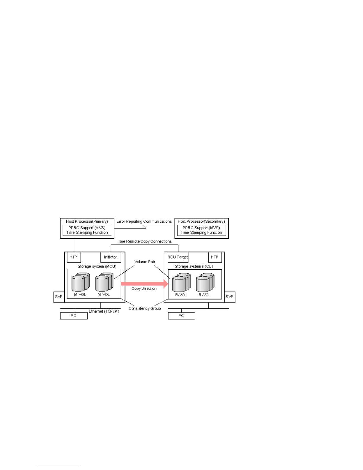
Typical components
A typical configuration consists of the following elements. Many but not all require user set up.
• A P9500 system—on the local side connected to a host. The system on the remote side, which
may be a P9500 system, must be connected to the local array via Fibre Channel data paths.
The remote array may consist of a different model—XP12000 Disk Array/XP10000 Disk
Array, and so on.
• A host at the local site, connected to the local disk array. It is also highly desirable to have a
host at the secondary site connected to the remote system for use in disaster recovery. If this
is not possible, the local host must have channel connections to the remote disk array for the
data to be used in the event of a disaster.
• A volume (M-VOL) on the local system that is copied to a volume (R-VOL) on the remote system.
• Fibre Channel data paths for data transfer between the local and remote disk arrays.
• Initiator and RCU target ports for the Fibre Channel interface.
• Remote Web Console graphical user interface software, used to perform Continuous Access
Synchronous Z configuration and pair operations. Alternatively, Business Continuity Manager
(BCM) and PPRC commands can be used for pair operations.
The following shows a typical Continuous Access Synchronous Z environment.
Figure 1 Continuous Access Synchronous Z components
Disk arrays
This guide documents Continuous Access Synchronous Z operations in which the main system is
a P9500 and the remote system is a P9500, XP24000/XP20000 Disk Array, or XP12000 Disk
Array/XP10000 Disk Array.
• The main disk array consists of a main control unit (MCU) and service processor (SVP).
• The remote disk array consists of the remote control unit (RCU) and the SVP.
The main and remote disk arrays are often referred to as the MCU and RCU.
The main disk array communicates with the remote disk array over dedicated Fibre Channel data
paths.
8 Continuous Access Synchronous Z overview
Page 9
Main (MCU), remote (RCU) disk arrays
The main disk array manages the M-VOL and the following operations:
• Host I/O operations to the M-VOL
• Initial copy and update copy operations between the M-VOL and R-VOL.
• Pair status and configuration information
The remote disk array manages the R-VOL and the following operations:
• Remote copy operations issued by the main system
• Assists in managing pair status and configuration (for example, rejects write I/Os to the R-VOL).
The P9500 CU can function simultaneously as a main disk array for one or more M-VOLs, and as
a remote disk array for one or more R-VOLs. This kind of configuration requires that data paths
and Fibre Channel ports to be properly configured for both copy directions.
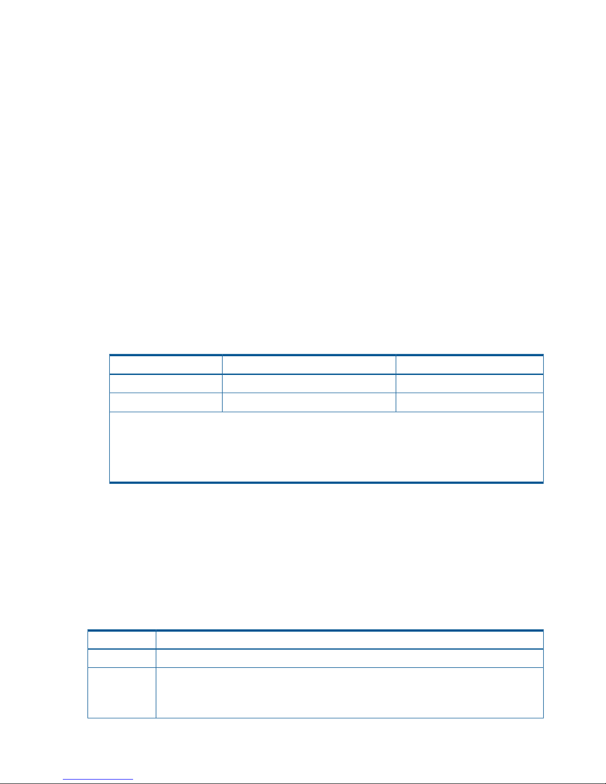
When you use XP12000 Disk Array/XP10000 Disk Array for MCU or RCU, the CU number that
can be used is limited. The following table provides the CU number range when P9500,
XP24000/XP20000 Disk Array, or XP12000 Disk Array/XP10000 Disk Array is used for MCU
or RCU.
Table 1 CU number range when P9500, XP24000/XP20000 Disk Array, or XP12000 Disk
Array/XP10000 Disk Array is used for MCU or RCU
RCUMCU
P9500XP24000/XP20000 Disk
Array
XP12000 Disk
Array/XP10000 Disk Array
MCU:0x00 to 0x3fMCU:0x00 to 0x3fMCU:0x00 to 0x3fXP12000 Disk
Array/XP10000 Disk Array
RCU:0x00 to 0x3fRCU:0x00 to 0x3fRCU:0x00 to 0x3f
MCU:0x00 to 0xfeMCU:0x00 to 0xfeMCU:0x00 to 0x3fXP24000/XP20000 Disk
Array
RCU:0x00 to 0xfeRCU:0x00 to 0xfeRCU:0x00 to 0x3f
MCU:0x00 to 0xfeMCU:0x00 to 0xfeMCU:0x00 to 0x3fP9500
RCU:0x00 to 0xfeRCU:0x00 to 0xfeRCU:0x00 to 0x3f
IMPORTANT: If you are creating a Continuous Access Synchronous Z pair with different series
of disk arrays (for example, P9500 and XP12000 Disk Array/XP10000 Disk Array), make sure
that each disk array has a unique serial number. It is possible that a serial number overlap could
occur (although this would be extremely rare). If you have two disk arrays with the same serial
number and you need to configure remote copy pairs between the two storage systems, contact
your HP account team for assistance.
Volume pairs
As described above, data written from the mainframe host is stored in the M-VOL and the remote
copy is stored in the R-VOL. The pair can be suspended, resynchronized, reverse resynchronized,
and returned to the Simplex state.
• When paired, the volumes are synchronized.
• When suspended, new data is sent to the M-VOL but not the R-VOL.
• When resynchronized, changed data is copied to the R-VOL.
• When necessary, data in the R-VOL can be copied to the M-VOL.
During normal operations, the M-VOL remains available to the host for read and write I/O
operations. The remote system rejects write I/Os for the R-VOL, unless the write-enable option is
Volume pairs 9
Page 10

specified for the R-VOL. Then, write I/O is allowed to the R-VOL while the pair is suspended. In
this instance, R-VOL and M-VOL track maps keep track of differential data and are used to
resynchronize the pair.
Volumes on the local and remote systems must be defined and formatted prior to pairing.
Data path
Continuous Access Synchronous Z operations are carried out between local and remote disk arrays
connected by a Fibre Channel interface. The data path, also referred to as the remote copy
connection, connects ports on the local P9500 system to the ports on the remote disk array. The
ports are assigned attributes that allow them to send and receive data.
One data path connection is required, but two or more independent connections are recommended,
for hardware redundancy. A maximum of eight paths per control unit (CU) can be used.
Consistency groups
A consistency group is a set of volume pairs that are in the same main and remote system on which
copy operations are performed simultaneously, and in which the pairs status remains consistent.
When you issue a command, it is executed on all pairs in the group. The pairs pair status changes
at the same time, depending on the group options.
Yet, while consistency is a primary function of a group, certain operations take priority. For example,
if the Suspended commend is issued to a consistency group in which one of the pairs is in the
process of being updated, the pair is not suspended immediately, as all the other pairs are. It is
suspended only when the update operation is completed. This allows for data integrity to be
maintained between M-VOLs and R-VOLs. The same behavior occurs for a suspended operation
caused by system failure.
Continuous Access Synchronous Z operations can be performed on pairs in a maximum of 128
consistency groups on the main system.
Interfaces
You perform Continuous Access Synchronous Z operations using any of the following interfaces:
• Remote Web Console, a browser-based interface from which Continuous Access Synchronous
Z can be setup, operated, and monitored. The GUI provides the simplest method for performing
operations, requiring no previous experience.
◦ The main disk array must be LAN-attached to a Remote Web Console computer.
◦ The remote disk array should also be LAN-attached to a separate Remote Web Console
at the remote site. This allows you to perform operations more efficiently on the remote
disk array in the event that the main site is not available.
• Configuration, pair operations, and pair status monitoring can be performed using Business
Continuity Manager commands from the host to the disk array.
• Most operations can be performed using PPRC commands from the host. All P9500 systems
support IBM PPRC host software functions.
Failover software
Host failover software is used to transfer information between host servers at the local and remote
sites. It is a critical component of any disaster recovery solution.
• When Continuous Access Synchronous Z is used as a disaster recovery tool, host failover is
required to insure effective recovery operations.
• When Continuous Access Synchronous Z is used as a data migration tool, host failover is
recommended.
10 Continuous Access Synchronous Z overview
Page 11
Continuous Access Synchronous Z does not provide host-failover functions. Use the failover software
most suitable for your platform and requirements.
Error reporting communications
Error reporting communications (ERC) transfers information between host processors at the main
and remote sites. It is a critical component of a disaster recovery effort.
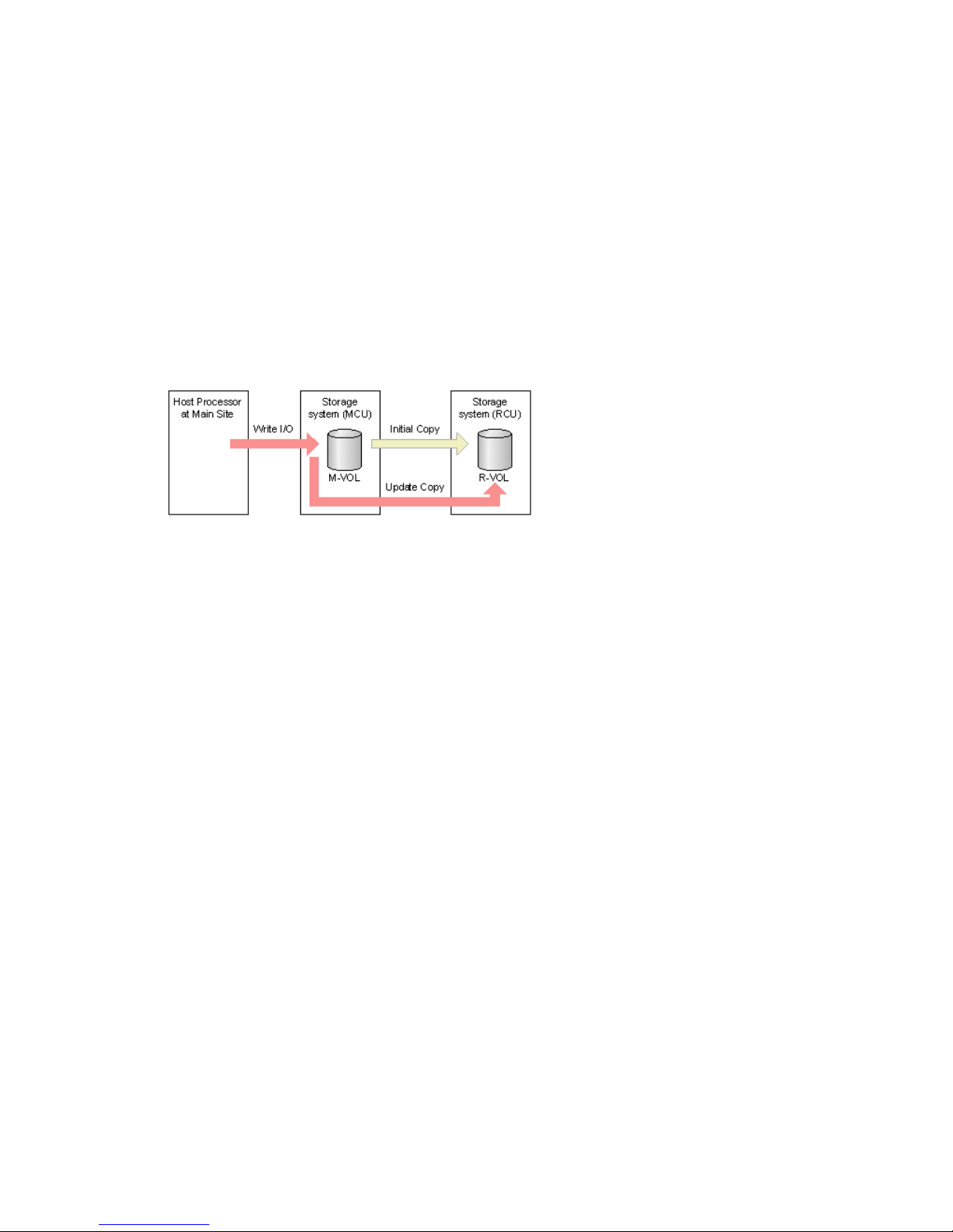
Overview of initial, update copy operations
When you perform the initial copy operation, all the data in the M-VOL is copied into the R-VOL.
Thereafter, Continuous Access Synchronous Z and the main and remote systems execute update
copy as often as writes are sent by the host. The update operation copies host updates to the R-VOL
at the same time that they are copied to the M-VOL.
The following figure illustrates the initial and the update copy operations.
Figure 2 Remote copy operations
Initial copy
When a new pair is created, the entire contents of the M-VOL are copied to the R-VOL, cylinder
by track (this does not include for diagnostic and unassigned alternate tracks). The initial copy
synchronizes the M-VOL and R-VOL, independently of host I/O processes.
In an initial copy, you can elect to have no data copied if the M-VOL and R-VOL are already
identical. You can also specify options that provide additional flexibility between the speed of
data transfer and system performance.
• The copy pace option allows you to specify the maximum number of tracks (1-15) that can be
copied simultaneously before the main system accepts another host request for that M-VOL. If
more tracks are copied, the operation completes more quickly; if fewer tracks are copied,
performance is maintained at a higher level.
• The priority option allows you to specify the order in which copying is performed on multiple
pairs. This is used if more pairs are being created than the maximum initial copy activity
setting.
• The maximum initial copy activity option allows you to specify the maximum number of
concurrent initial copy and resync copy operations that each main system performs (not
pair-specific).
• The Round Trip Time option allows you to specify the time limit for data to travel from the
M-VOL to R-VOL. This value is used by the system to control initial copy pace when update
copying is in progress.
These options are available on Remote Web Console only.
Update copy
If the host issues an update after the initial copy is complete, the data is written to the M-VOL and
copied to the R-VOL. The write operation is acknowledged to the host as complete after the data
is copied to the R-VOL in the RCU.
Error reporting communications 11
Page 12

Update copy has a higher priority than initial copy. However, if an initial copy is in progress when
updates are sent by the host, the update copy must wait until the initial copy’s copy pace completes.
For example, if the copy pace is 15 tracks, the update copy may wait up to 15 tracks (1 cylinder).
12 Continuous Access Synchronous Z overview
Page 13

2 Requirements and specifications
This chapter provides basic system requirements, along with specifications for BCM, PPRC, and
other mainframe-related interfaces and functions. In addition to the information in this chapter,
“Planning for Continuous Access Synchronous Z” (page 25) provides many specifications,
recommendations, and restrictions for the elements of a Continuous Access Synchronous Z system
that require attention before setting up and using Continuous Access Synchronous Z.
System requirements
Continuous Access Synchronous Z operations require P9500 main and remote disk array containing
the M-VOLs and R-VOLs, data paths between the disk arrays, host(s) on the primary and remote
sites, and interface software.
The following lists and describe general requirements.
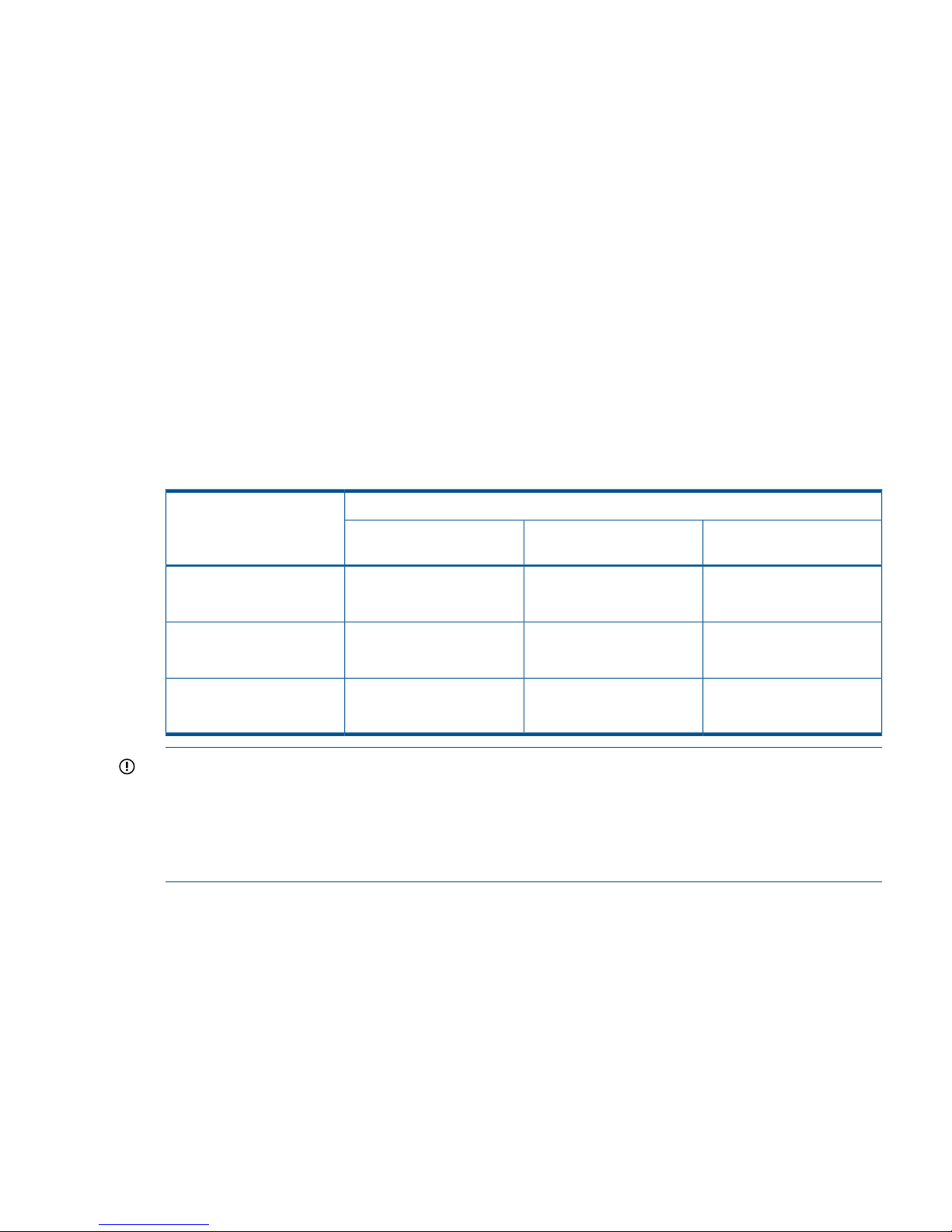
Table 2 General system requirements
RequirementItem
3390-1, 3390-2, 3390-3, 3390-9, 3390-L, 3380-3, 3390-MSupported device
emulation types
Main and remote sites
• At the main site, P9500 is required.
• At the remote site, the following models can be used:
P9500
XP24000/XP20000 Disk Array (60–07–51–xx/xx or later)
XP12000/XP10000 Disk Array (50–09–98–xx/xx or later)
Contact your HP team for assistance.
Continuous Access Synchronous Z supports RAID 1, RAID 5, and RAID6 configurations.RAID levels supported
Continuous Access
Synchronous Z
• Separate license keys are required for each system.
• Must be installed on main and remote system
• Synchronous only. P9500 does not support Asynchronous.
• Can co-exist with Continuous Access Synchronous.
None.Other required licenses
Supported mainframe host
operating systems
• zLinux
• OS/390
• zOS
• z/VM
• z/VSE
Contact your HP account team for the latest information.
Mainframe related
• IBM PPRC is supported.
• If the R-VOL is assigned to the M-VOL of Continuous Access Journal Z, and the main
and/or remote systems consist of several CPU complexes, a SYSPLEX timer is required
to provide a common time reference for the host I/O timestamping function.
Contact your HP account team for the latest information.
Fibre Channel (FICON), direct or with switch connections. See “Planning data paths”
(page 34).
8 paths at maximum, from MCU to RCU.
Data path
System requirements 13
Page 14

Table 2 General system requirements (continued)
RequirementItem
Logical paths
• Maximum of eight from main disk array to remote disk array.
• Logical paths are established for main and remote disk array CUs separately.
• Maximum number of logical paths allowed for a disk array is 32 (8 paths per remote
system X 4 remote systems per main system).
Maximum number of
remote systems
• Maximum of four remote systems per main system.
• Each remote system CU must be added separately to a main system.
Pair volumes
• M-VOL and R-VOL must be the same size and emulation.
• One M-VOL may only be copied to one R-VOL.
• M-VOL and R-VOL can be shared with other program product volumes. See “Volume
types that can be shared with Continuous Access Synchronous Z” (page 39).
See “Planning volume pairs” (page 29) on for more information.
Limited per P9500 system. See “Maximum number of pairs supported” (page 31).Number of pairs
Must be insured by the user. The track format for the M-VOL and R-VOL must meed the
following requirements:
Disk Track Format
• The M-VOL and R-VOL must have the same track format.
• Record zero (R0) must be standard format, with key length of zero and data length of
eight. The main system aborts the initial copy operation if R0 is not standard format.
• The CCHH (logical cylinder address and logical head address) of R0 must be identical
to the physical cylinder address and physical head address of the track.
• The CCHH of each user record in a track must be unique.
Error Reporting
Communications (ERC)
software
• Required for disaster recovery.
• Recommended for data migration.
See “Error reporting communications” (page 37) for more information.
Continuous Access
Synchronous Z Interfaces
• Remote Web Console
Required.◦
◦ Storage Administrator (Remote Copy) role is required.
◦ The main system must be LAN-attached to a Remote Web Console computer.
◦ The remote system should be attached using a separate LAN at the remote site.
• BCM
Optional.◦
◦ Command device required.
See “BCM specifications ” (page 14).
• PPRC
◦ Optional.
See “PPRC specifications, restrictions ” (page 17).
BCM specifications
Pair operations may be performed using BCM commands from the host system to the disk array.
With BCM commands, you can add, suspend, resynchronize, and delete pairs, as well as monitor
pair status. You can also create the Continuous Access Synchronous Z association between main
and remote system (add RCU).
14 Requirements and specifications
Page 15
NOTE: Although the same Continuous Access Synchronous Z pair operations may be performed
by using Business Continuity Manager or PPRC, Business Continuity Manager and PPRC are
independent functions. Do not use Business Continuity Manager and PPRC for the same pair
operation.
The following tables show the correspondence between the LINK parameters (ports) and (system
adapter ID) values.
For more information on BCM, see the HP P9000 for Business Continuity Manager Software User
Guide. Also see Table 6 (page 19) for corresponding PPRC functionality.
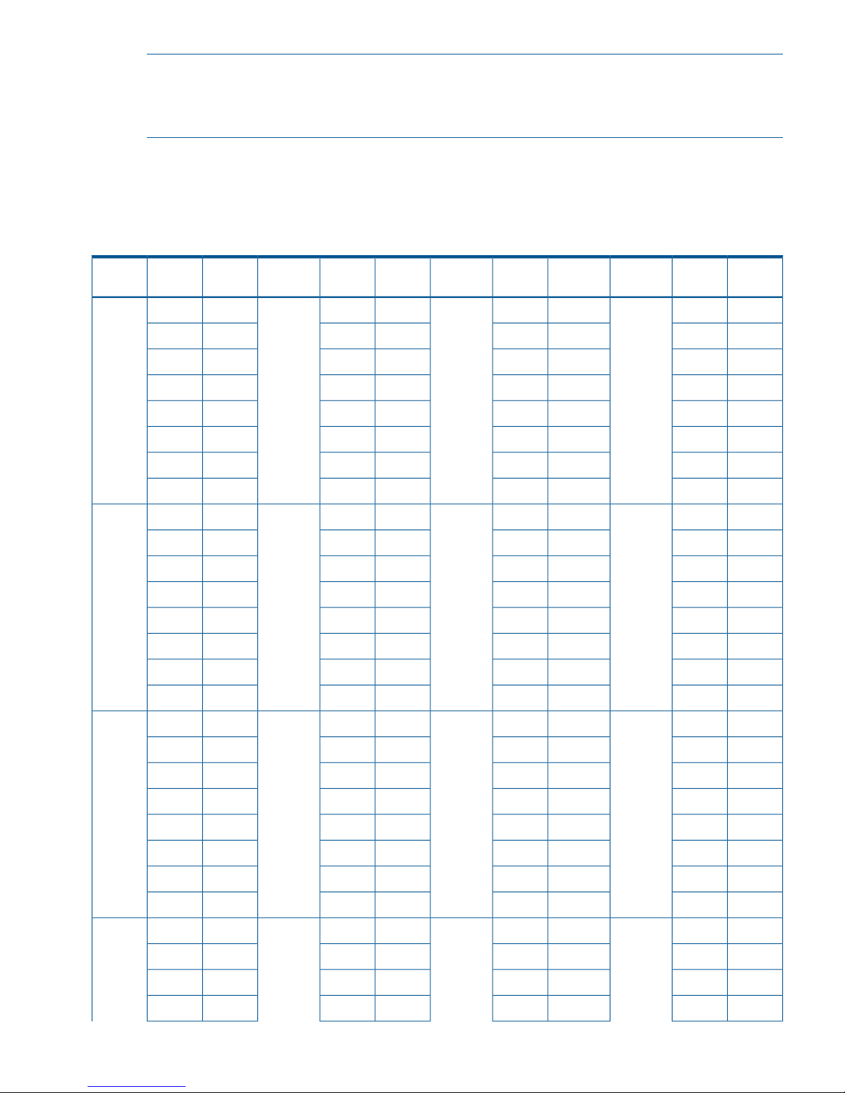
Table 3 SAID values for PATH LINK (CL1)
SAIDPortPackage
Local
SAIDPortPackage
Local
SAIDPortPackage
Local
SAIDPortPackage
Local
X'0088'CL9-J1LUX'0080'CL9-A1AUX'0008'CL1-J1GUX'0000'CL1-A1EU
(DKA
Add2)
(DKA
Basic)
(Add4)(Basic)
X'00A8'CLB-JX'00A0'CLB-AX'0028'CL3-JX'0020'CL3-A
X'00C8'CLD-JX'00C0'CLD-AX'0048'CL5-JX'0040'CL5-A
X'00E8'CLF-JX'00E0'CLF-AX'0068'CL7-JX'0060'CL7-A
X'0089'CL9-KX'0081'CL9-BX'0009'CL1-KX'0001'CL1-B
X'00A9'CLB-KX'00A1'CLB-BX'0029'CL3-KX'0021'CL3-B
X'00C9'CLD-KX'00C1'CLD-BX'0049'CL5-KX'0041'CL5-B
X'00E9'CLF-KX'00E1'CLF-BX'0069'CL7-KX'0061'CL7-B
X'008A'CL9-L1LLX'0082'CL9-C1ALX'000A'CL1-L1GLX'0002'CL1-C1EL
(DKA
Add3)
(DKA
Add1)
(Add5)(Add1)
X'00AA'CLB-LX'00A2'CLB-CX'002A'CL3-LX'0022'CL3-C
X'00CA'CLD-LX'00C2'CLD-CX'004A'CL5-LX'0042'CL5-C
X'00EA'CLF-LX'00E2'CLF-CX'006A'CL7-LX'0062'CL7-C
X'008B'CL9-MX'0083'CL9-DX'000B'CL1-MX'0003'CL1-D
X'00AB'CLB-MX'00A3'CLB-DX'002B'CL3-MX'0023'CL3-D
X'00CB'CLD-MX'00C3'CLD-DX'004B'CL5-MX'0043'CL5-D
X'00EB'CLF-MX'00E3'CLF-DX'006B'CL7-MX'0063'CL7-D
------X'000C'CL1-N1HUX'0004'CL1-E1FU
(Add6)(Add2)
----X'002C'CL3-NX'0024'CL3-E
----X'004C'CL5-NX'0044'CL5-E
----X'006C'CL7-NX'0064'CL7-E
----X'000D'CL1-PX'0005'CL1-F
----X'002D'CL3-PX'0025'CL3-F
----X'004D'CL5-PX'0045'CL5-F
----X'006D'CL7-PX'0065'CL7-F
------X'000E'CL1-Q1HLX'0006'CL1-G1FL
(Add7)(Add3)
----X'002E'CL3-QX'0026'CL3-G
----X'004E'CL5-QX'0046'CL5-G
----X'006E'CL7-QX'0066'CL7-G
BCM specifications 15
Page 16

Table 3 SAID values for PATH LINK (CL1) (continued)
SAIDPortPackage
Local
SAIDPortPackage
Local
SAIDPortPackage
Local
SAIDPortPackage
Local
----X'000F'CL1-RX'0007'CL1-H
----X'002F'CL3-RX'0027'CL3-H
----X'004F'CL5-RX'0047'CL5-H
----X'006F'CL7-RX'0067'CL7-H
Table 4 SAID values for PATH LINK (CL2)
SAIDPortPackage
Local
SAIDPortPackage
Local
SAIDPortPackage
Local
SAIDPortPackage
Local
X'0098'CLA-J2XUX'0090'CLA-A2MUX'0018'CL2-J2TUX'0010'CL2-A2QU
(DKA
Add2)
(DKA
Basic)
(Add4)(Basic)
X'00B8'CLC-JX'00B0'CLC-AX'0038'CL4-JX'0030'CL4-A
X'00D8'CLE-JX'00D0'CLE-AX'0058'CL6-JX'0050'CL6-A
X'00F8'CLG-JX'00F0'CLG-AX'0078'CL8-JX'0070'CL8-A
X'0099'CLA-KX'0091'CLA-BX'0019'CL2-KX'0011'CL2-B
X'00B9'CLC-KX'00B1'CLC-BX'0039'CL4-KX'0031'CL4-B
X'00D9'CLE-KX'00D1'CLE-BX'0059'CL6-KX'0051'CL6-B
X'00F9'CLG-KX'00F1'CLG-BX'0079'CL8-KX'0071'CL8-B
X'009A'CLA-L2XLX'0092'CLA-C2MLX'001A'CL2-L2TLX'0012'CL2-C2QL
(DKA
Add3)
(DKA
Add1)
(Add5)(Add1)
X'00BA'CLC-LX'00B2'CLC-CX'003A'CL4-LX'0032'CL4-C
X'00DA'CLE-LX'00D2'CLE-CX'005A'CL6-LX'0052'CL6-C
X'00FA'CLG-LX'00F2'CLG-CX'007A'CL8-LX'0072'CL8-C
X'009B'CLA-MX'0093'CLA-DX'001B'CL2-MX'0013'CL2-D
X'00BB'CLC-MX'00B3'CLC-DX'003B'CL4-MX'0033'CL4-D
X'00DB'CLE-MX'00D3'CLE-DX'005B'CL6-MX'0053'CL6-D
X'00FB'CLG-MX'00F3'CLG-DX'007B'CL8-MX'0073'CL8-D
------X'001C'CL2-N2UUX'0014'CL2-E2RU
(Add6)(Add2)
----X'003C'CL4-NX'0034'CL4-E
----X'005C'CL6-NX'0054'CL6-E
----X'007C'CL8-NX'0074'CL8-E
----X'001D'CL2-PX'0015'CL2-F
----X'003D'CL4-PX'0035'CL4-F
----X'005D'CL6-PX'0055'CL6-F
----X'007D'CL8-PX'0075'CL8-F
------X'001E'CL2-Q2ULX'0016'CL2-G2RL
(Add7)(Add3)
----X'003E'CL4-QX'0036'CL4-G
----X'005E'CL6-QX'0056'CL6-G
----X'007E'CL8-QX'0076'CL8-G
16 Requirements and specifications
Page 17
Table 4 SAID values for PATH LINK (CL2) (continued)
SAIDPortPackage
Local
SAIDPortPackage
Local
SAIDPortPackage
Local
SAIDPortPackage
Local
----X'001F'CL2-RX'0017'CL2-H
----X'003F'CL4-RX'0037'CL4-H
----X'005F'CL6-RX'0057'CL6-H
----X'007F'CL8-RX'0077'CL8-H
Command device
Business Continuity Manager requires a command device on the Continuous Access Synchronous
Z disk array that is independent of the command device for an open system. The command device
for BCM can be configured only from BCM.
To find the command device using Remote Web Console:
1. In Remote Web Console, click File/Reports. The Report Display window displays.
2. Click the LDEV tab.
If you are using XP12000 Disk Array/XP10000 Disk Array, only the volumes with a CU: LDEV
number between 00: 00 to 3F: FF can be used as command devices.
F/M = FB message output control option when operating R-VOLs
When the suspension or the release operation is performed from Business Continuity Manager
(BCM) to the R-VOL of Continuous Access Synchronous Z pair in the Duplex status, the status of
the M-VOL becomes Suspend and the F/M = FB message is output to the host connected to MCU.
You can control the output of this message by setting the system option mode 776.
However, even if the system option mode 776 is set, the F/M = FB message is output when the
pair status becomes Suspend due to the failure. Moreover, the F/M = FB message is not output
regardless of the setting of system option mode 776 if PPRC support by host = No is selected on
the CU Option dialog box.
Table 5 Whether to output the F/M = FB message when operating R-VOLs
SettingsCause of the
suspension of M-VOL
The system option mode 776 is OFFThe system option mode 776 is ON
PPRC support by host
= No
PPRC support by host
= Yes
PPRC support by host
= No
PPRC support by host
= Yes
NoYesNoNoSuspended by the
suspension or the
release operation from
BCM to R-VOLs
NoYesNoYesSuspended by failure
PPRC specifications, restrictions
Most Continuous Access Synchronous Z operations can be performed using PPRC TSO or ICKDSF
PPRCOPY commands from the host system console. All P9500 systems support IBM PPRC host
software functions.
PPRC specifications, restrictions 17
Page 18

Continuous Access Synchronous Z operations performed with PPRC
Using PPRC commands, you can perform the following operations:
• Create, suspend, resynchronize, and delete Continuous Access Synchronous Z pairs
• Suspend, resynchronize, and delete Continuous Access Synchronous Z consistency groups
• Establish and delete data paths
• View path and pair status
The following applies when using PPRC commands:
• The P9500 is capable of automatically configuring a Fibre Channel port as an initiator or
RCU target port, if required, in response to the TSO CESTPATH and CDELPATH commands.
Initiator and RCU target ports are required for sending and receiving data to and from the
main and remote system. System option mode 114 must be enabled for automatic port
configuration in response to PPRC commands. Only HP Technical Support can set System
Option Modes.
◦ The P9500 makes sure that the main disk array port specified for an interconnecting link
is offline to a host, and automatically configures it as an initiator port if required. Similarly,
the corresponding remote disk array port is configured as an RCU target port when
required.
When the CDELPATH command is issued, Continuous Access Synchronous Z logical paths
are removed. If there are no more Continuous Access Synchronous Z logical paths on
the port, the port is automatically changed from initiator port to RCU target port.
◦ If the ports are in initiator/external mix mode, initiator ports do not automatically change
to RCU target ports, nor to RCU target ports automatically change to initiator ports, even
though system option mode 114 is enabled.
• Relating to the Fibre Channel interface, do not use the CESTPATH and CDELPATH commands
when using LUN Manager’s SCSI path definition function. Fibre Channel ports must be
configured as initiator or RCU target ports before the CESTPATH and CDELPATH commands
are issued.
NOTE: Ensure that the relevant paths are offline before issuing the CESTPATH command.
The add path operation fails if active logical paths exist, because the port attribute cannot be
changed.
Continuous Access Synchronous Z options not supported with PPRC
The following Continuous Access Synchronous Z options cannot be changed using PPRC. Use
Remote Web Console to change these options.
• RCU and CU options. The following default values are used for these options:
Minimum Paths = 1◦
◦ RIO MIH Time = 15 sec
18 Requirements and specifications
Page 19

◦ PPRC Support = Yes
◦ Service SIM of Remote Copy = Not Report
• Initial copy priority, the CFW (cache fast write) Data option, and DFW (DASD fast write) to
R-VOL option. If CESTPAIR is used to create a pair, the following values are used for these
options. Use Remote Web Console to change these options.
◦ Initial copy priority = 0
◦ CFW Data = Copy to R-VOL. If you select the only M-VOL value, the data set that is
updated by CFW in the M-VOL cannot be used in the R-VOL. To use this data set in the
R-VOL, release the pair and format the data set.
◦ CFW Data = only M-VOL can be set with a PPRC command when the Remote Copy
Function Switch is used. Contact your HP account team for more information.
◦ DFW to R-VOL = DFW not required. This setting does not affect M-VOL I/O performance.
If one side of cache is closed due to a remote system failure, the copy operation still uses
DFW. The difference between not required and required is that new pairs cannot be
established with the required option when one side of RCU cache is closed. In this case,
the Add Pair operation fails (This restriction applies only when the CU emulation type of
RCU is 3390).
PPRC, BCM command comparison
BCM and PPRC are independent functions. Do not use BCM and PPRC for the same pair operation.
The following lists the PPRC commands that correspond BCM commands.
Table 6 Corresponding PPRC, BCM commands
Support typeBCM commandParameterPPRC command
configYKBLDPTHDEVNCESTPATH
configPRIM
configSEC
configLINK
Not supportedCGROUP
Not supportedRESETHP
configYKMAKE/YKRESYNCDEVNCESTPAIR
configPRIM
configSEC
Command (RESYNC)MODE
Parameter (NOCOPY)
config (CopyPace)PACE
config (ErrorLevel)CRIT
Not supportedMSGREQ
Not supportedONLINSEC
configYKSUSPND
*1
DEVNCSUSPEND
configPRIM
configSEC
Not supportedPRIMARY
PPRC specifications, restrictions 19
Page 20

Table 6 Corresponding PPRC, BCM commands (continued)
Support typeBCM commandParameterPPRC command
Not supportedQUIESCE
configYKDELETEDEVNCDELPAIR
PRIM
SEC
configYKRECOVERDEVNCRECOVER
PRIM
SEC
ID
configYKQUERYDEVNCQUERY
Not supportedFORMAT/UNFORMAT
Not supportedVOLUME/PATHS
configYKFREEZE/YKRUNDEVNCGROUP
configPRIM
configSEC
commandFREEZE/RUN
configYKDELPTHDEVNCDELPATH
configPRIM
configSEC
*1. The YKSUSPEND command supports only the pair suspend command for M-VOL.
P/DAS support, restrictions
Continuous Access Synchronous Z supports the IBM P/DAS host software function. P/DAS allows
you to relocate or migrate data by redirecting all application I/Os from the M-VOL to the R-VOL
without interrupting access to the data. See the following IBM publications for important information
on the requirements and procedures for P/DAS operations: Planning for IBM Remote Copy
(SG24-2595), Advanced Copy Services (SC35-0355), DFSMS MVS V1 Remote Copy Guide and
Reference (SC35-0169).
Restrictions
The following restrictions apply to P/DAS use with Continuous Access Synchronous Z:
• P/DAS through channel extenders is not supported.
• P/DAS does not support CFW operations. You must stop CFW applications before performing
P/DAS operations on Continuous Access Synchronous Z volumes.
• P/DAS swap option #2 (switch pair & swap) is supported for P/DAS between the P9500 and
XP12000 Disk Array/XP10000 Disk Array storage systems.
Contact your HP account team for the latest information on P/DAS support.
GDPS support
Continuous Access Synchronous Z provides remote copy support for IBM’s Geographically Dispersed
Parallel Sysplex® (GDPS) facility. GDPS is an IBM service for mirroring data and balancing
20 Requirements and specifications
Page 21

workload on disk arrays spread across two or more sites up to 40 km (20 miles) apart. With this
support, users who are running IBM Parallel Sysplex systems can take advantage of the P9500’s
suite of remote copy options for data availability.
GDPS operations feature automatic control of groups of PPRC-managed volumes using host-based
scripts and PPRC commands; for example, CGROUP (FREEZE/RUN). GDPS support may have
additional installation requirements for Continuous Access Synchronous Z main and remote system,
depending on the P9500 firmware and Continuous Access Synchronous Z versions.
Check the following items with your HP representative:
• The P9500 does not support controlling the FREEZE Option through the CESTPATH LINK
parameter. The FREEZE Option must be controlled using the CGROUP option of CESTPATH.
• Please make changes as needed to the CESTPATH LINK definitions in your GDPS configuration
files or configuration database.
For more information on GDPS, see the following IBM publications: Geographically Dispersed
Parallel Sysplex: the S/390 Multi-site Application Availability Solution, Executive Summary
(GF22-5114); and Geographically Dispersed Parallel Sysplex: the S/390 Multi-site Application
Availability Solution (GF22-5063).
RMF PPRC Link-path statistical information support
When you use z/OS Resource Measurement Facility (RMF), and if you specify the IBM TotalStorage
Enterprise Storage Server (ESS), you can acquire PPRC Fibre Link-path statistical information.
If the total size of the data for the data-acquisition interval is 100 KB and below, zero may be
reported for the data size.
The following two tables show P9500 system adaptor IDs (SAID) for the LINK parameters (ports)
that display when PPRC Link-path statistical information is acquired with RMF.
The P9500 system adaptor ID (SAID) values in the following tables are different from the ones for
the LINK parameters of CESTPATH TSO commands (see Table 3 (page 15) and Table 4 (page
16)).
Table 7 SAID values for Link-path statistical Information (CL1)
SAIDPortPackage
Local
SAIDPortPackage
Local
SAIDPortPackage
Local
SAIDPortPackage
Local
X'0060'CL9-J1LUX'0040'CL9-A1AUX'0020'CL1-J1GUX'0000'CL1-A1EU
(DKA
Add2)
(DKA
Basic)
(Add4)(Basic)
X'0061'CLB-JX'0041'CLB-AX'0021'CL3-JX'0001'CL3-A
X'0062'CLD-JX'0042'CLD-AX'0022'CL5-JX'0002'CL5-A
X'0063'CLF-JX'0043'CLF-AX'0023'CL7-JX'0003'CL7-A
X'0064'CL9-KX'0044'CL9-BX'0024'CL1-KX'0004'CL1-B
X'0065'CLB-KX'0045'CLB-BX'0025'CL3-KX'0005'CL3-B
X'0066'CLD-KX'0046'CLD-BX'0026'CL5-KX'0006'CL5-B
X'0067'CLF-KX'0047'CLF-BX'0027'CL7-KX'0007'CL7-B
X'0070'CL9-L1LLX'0050'CL9-C1ALX'0030'CL1-L1GLX'0010'CL1-C1EL
(DKA
Add3)
(DKA
Add1)
(Add5)(Add1)
X'0071'CLB-LX'0051'CLB-CX'0031'CL3-LX'0011'CL3-C
X'0072'CLD-LX'0052'CLD-CX'0032'CL5-LX'0012'CL5-C
X'0073'CLF-LX'0053'CLF-CX'0033'CL7-LX'0013'CL7-C
X'0074'CL9-MX'0054'CL9-DX'0034'CL1-MX'0014'CL1-D
X'0075'CLB-MX'0055'CLB-DX'0035'CL3-MX'0015'CL3-D
RMF PPRC Link-path statistical information support 21
Page 22
Table 7 SAID values for Link-path statistical Information (CL1) (continued)
SAIDPortPackage
Local
SAIDPortPackage
Local
SAIDPortPackage
Local
SAIDPortPackage
Local
X'0076'CLD-MX'0056'CLD-DX'0036'CL5-MX'0016'CL5-D
X'0077'CLF-MX'0057'CLF-DX'0037'CL7-MX'0017'CL7-D
------X'0028'CL1-N1HUX'0008'CL1-E1FU
(Add6)(Add2)
----X'0029'CL3-NX'0009'CL3-E
----X'002a'CL5-NX'000a'CL5-E
----X'002b'CL7-NX'000b'CL7-E
----X'002c'CL1-PX'000c'CL1-F
----X'002d'CL3-PX'000d'CL3-F
----X'002e'CL5-PX'000e'CL5-F
----X'002f'CL7-PX'000f'CL7-F
------X'0038'CL1-Q1HLX'0018'CL1-G1FL
(Add7)(Add3)
----X'0039'CL3-QX'0019'CL3-G
----X'003a'CL5-QX'001a'CL5-G
----X'003b'CL7-QX'001b'CL7-G
----X'003c'CL1-RX'001c'CL1-H
----X'003d'CL3-RX'001d'CL3-H
----X'003e'CL5-RX'001e'CL5-H
----X'003f'CL7-RX'001f'CL7-H
Table 8 SAID values for Link-path statistical Information (CL2)
SAIDPortPackage
Local
SAIDPortPackage
Local
SAIDPortPackage
Local
SAIDPortPackage
Local
X'00e0'CLA-J2XUX'00c0'CLA-A2MUX'00a0'CL2-J2TUX'0080'CL2-A2QU
(DKA
Add2)
(DKA
Basic)
(Add4)(Basic)
X'00e1'CLC-JX'00c1'CLC-AX'00a1'CL4-JX'0081'CL4-A
X'00e2'CLE-JX'00c2'CLE-AX'00a2'CL6-JX'0082'CL6-A
X'00e3'CLG-JX'00c3'CLG-AX'00a3'CL8-JX'0083'CL8-A
X'00e4'CLA-KX'00c4'CLA-BX'00a4'CL2-KX'0084'CL2-B
X'00e5'CLC-KX'00c5'CLC-BX'00a5'CL4-KX'0085'CL4-B
X'00e6'CLE-KX'00c6'CLE-BX'00a6'CL6-KX'0086'CL6-B
X'00e7'CLG-KX'00c7'CLG-BX'00a7'CL8-KX'0087'CL8-B
X'00f0'CLA-L2XLX'00d0'CLA-C2MLX'00b0'CL2-L2TLX'0090'CL2-C2QL
(DKA
Add3)
(DKA
Add1)
(Add5)(Add1)
X'00f1'CLC-LX'00d1'CLC-CX'00b1'CL4-LX'0091'CL4-C
X'00f2'CLE-LX'00d2'CLE-CX'00b2'CL6-LX'0092'CL6-C
X'00f3'CLG-LX'00d3'CLG-CX'00b3'CL8-LX'0093'CL8-C
X'00f4'CLA-MX'00d4'CLA-DX'00b4'CL2-MX'0094'CL2-D
X'00f5'CLC-MX'00d5'CLC-DX'00b5'CL4-MX'0095'CL4-D
22 Requirements and specifications
Page 23
Table 8 SAID values for Link-path statistical Information (CL2) (continued)
SAIDPortPackage
Local
SAIDPortPackage
Local
SAIDPortPackage
Local
SAIDPortPackage
Local
X'00f6'CLE-MX'00d6'CLE-DX'00b6'CL6-MX'0096'CL6-D
X'00f7'CLG-MX'00d7'CLG-DX'00b7'CL8-MX'0097'CL8-D
------X'00a8'CL2-N2UUX'0088'CL2-E2RU
(Add6)(Add2)
----X'00a9'CL4-NX'0089'CL4-E
----X'00aa'CL6-NX'008a'CL6-E
----X'00ab'CL8-NX'008b'CL8-E
----X'00ac'CL2-PX'008c'CL2-F
----X'00ad'CL4-PX'008d'CL4-F
----X'00ae'CL6-PX'008e'CL6-F
----X'00af'CL8-PX'008f'CL8-F
------X'00b8'CL2-Q2ULX'0098'CL2-G2RL
(Add7)(Add3)
----X'00b9'CL4-QX'0099'CL4-G
----X'00ba'CL6-QX'009a'CL6-G
----X'00bb'CL8-QX'009b'CL8-G
----X'00bc'CL2-RX'009c'CL2-H
----X'00bd'CL4-RX'009d'CL4-H
----X'00be'CL6-RX'009e'CL6-H
----X'00bf'CL8-RX'009f'CL8-H
TPC-R cooperation support
The Basic HyperSwap function of TPC-R (IBM disaster recovery software) has the following
requirements:
• System option mode 114 is set to OFF.
• System option modes 484 and 769 are set to ON.
• Cnt Ac-S Z synchronous pairs are created after both the paths from MCU to RCU and from
RCU to MCU are established.
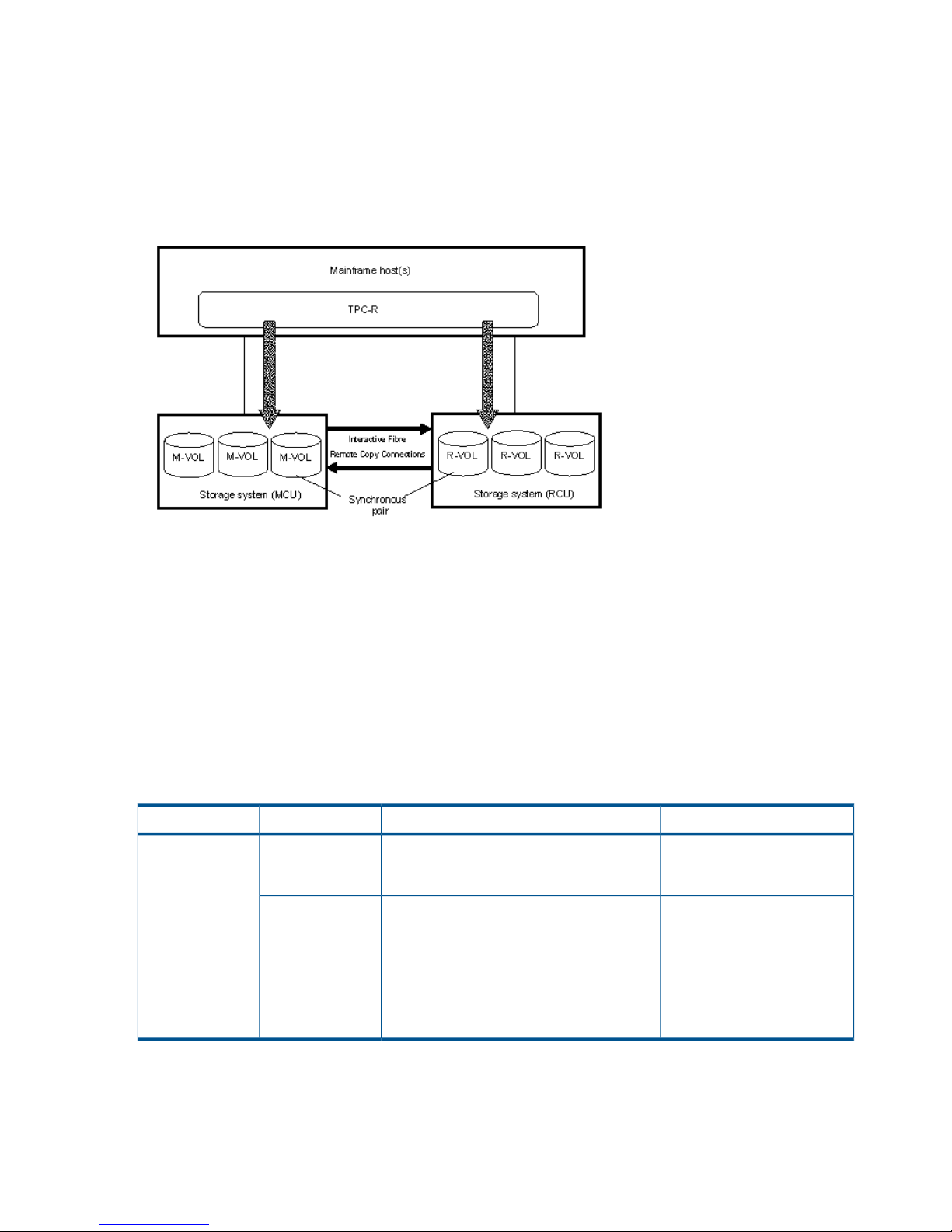
When performing a Basic HyperSwap to exchange M-VOLs and R-VOLs, Cnt Ac-S Z synchronous
pairs are resynchronized using the path that is already established (see “Configuration of Cnt Ac-S
Z synchronous pair M-VOLs and R-VOLs using TPC-R” (page 24). If a path is not established, Basic
HyperSwap will not complete correctly.
For optimal performance, the maximum number of pairs for Basic HyperSwap is 1,000 per CHA,
which is the path for accessing connected Cnt Ac-S Z volumes.
If Basic HyperSwap is performed from TPC-R, the MIH value of the host I/O and host operation
needs to be approximately one second.
If the Basic HyperSwap function is performed from TPC-R, the resources in the host system must be
ensured sufficiently. If the shortage of resources occurs, resynchronization for Cnt Ac-S Z synchronous
pair may fail with the messages of IOSHM0803E (HyperSwap Disabled) and IOSHM0201I (Reason
Code:40) in the host system. If the resynchronization failed, restore the resource shortage, and
then delete the failed M-VOL and R-VOL Cnt Ac-S Z pair in suspend status from the TPC-R. The pair
create operation must be initiated again after the failed pair deletion.
TPC-R cooperation support 23
Page 24
The Basic HyperSwap function performed from TPC-R may fail, when the FREEZE command process
does not complete within 20 seconds. We recommend the following conditions to complete the
FREEZE command process within 20 seconds.
• (Number of Host paths) x (Number of LPARs) x (Number of CGROUPs (Number of CUs)) ≤
160
• Number of pairs ≤ 4,096
Figure 3 Configuration of Cnt Ac-S Z synchronous pair M-VOLs and R-VOLs using TPC-R
Cache failure
When a cache failure occurs on the storage system, recover the cache failure, and then
resynchronize the Cnt Ac-S Z pair from TPC-R. Resynchronizing the Cnt Ac-S Z pair before recovering
the cache failure causes the resynchronization to fail. In this case, TPC-R issues a pair-deletion
command and resynchronizes the Cnt Ac-S Z pair automatically. All data in the M-VOL is recopied
to the R-VOL.
Unregistered error code for TPC-R
When using Basic HyperSwap, an unregistered error code for TPC-R might be displayed. In this
case, recover the Cnt Ac-S Z pair using the method described in the following table.
Table 9 Unregistered error code for TPC-R
Recovery procedureDescriptionOperationError code
Remove the failure on the
cache, and then retry the Cnt
Ac-S Z pair creation operation.
The Cnt Ac-S Z pair creation failed because
it was executed when a failure occurred in
the cache.
Pair creation0F0E
Remove the failure in the
cache, and then retry the Cnt
The Cnt Ac-S Z pair resynchronization
operation failed because it was executed
Pair
resynchronization
Ac-S Z pair resynchronization
operation.
when a failure occurred in the cache.
Although the Cnt Ac-S Z pair is deleted and
recreated (a whole copy) by the recovery
operation of TPC-R from the Cnt Ac-S Z pair
resynchronization failure, the recovery
operation fails.
24 Requirements and specifications
Page 25

3 Planning for Continuous Access Synchronous Z
This chapter provides information and instructions for planning main and remote system, pair
volumes, data paths, and the other elements.
Preparing P9500 disk arrays
The following preparations are required for the disk arrays in a Continuous Access Synchronous
Z pair relationship:
• Remote Web Console must be LAN-attached for the main and remote disk arrays. See the HP
P9000 Remote Web Console User Guide for information.
• The main and remote disk arrays must be set up for Continuous Access Synchronous Z
operations. See “Ensuring adequate cache” (page 25) and “Using DASD fast write” (page 25).
Make sure to consider the amount of Cache Residencydata that will be stored in cache when
determining the amount of cache for Continuous Access Synchronous Z operations.
• Set the system option modes, if needed, for your Continuous Access Synchronous Z
configuration on the main and remote disk arrays. See “Enabling R-VOL Read, other system
options” (page 26) for more information.
• Make sure that the main disk array is configured to report sense information to the host. The
remote disk array should also be attached to a host server for reporting of sense information
in the event of a problem with a R-VOL or remote system. If the remote disk array is not attached
to a host, it is recommended that it be attached to a main site host so that monitoring can be
performed.
• On the host operating system, make sure that the missing interrupt handler (MIH) value is set
high enough to accommodate the number of pairs, the cable length between the main and
remote system, and the initial copy pace. The recommended MIH value for Continuous Access
Synchronous Z operations is 60 seconds. For MVS, the MIH value is specified in the
SYS1.PARMLIB file. The recommended MIH value for Compatible XRC is different than for
Continuous Access Synchronous Z. If you are performing Continuous Access Synchronous Z
and Compatible XRC on the same disk array at the same time, contact your HP representative
for assistance.
• Install the data path between the main and remote system. Distribute data paths between
different storage clusters and extenders or switches to provide maximum flexibility and
availability. The logical paths between the main and remote system must be different than the
logical paths between the host and remote system. See “Planning data paths” (page 34) for
more information.
Ensuring adequate cache
Cache must be operable for the pair’s main and remote disk arrays; otherwise, the create pair
operation fails. The remote cache should be configured to adequately support Continuous Access
Synchronous Z remote copy workloads, as well as any local workload activity.
Installing or removing cache memory/shared memory
Cache memory/shared memory cannot be installed or removed when a Cnt Ac-S Z pair is in
Pending status. Check the pair status before installing or removing cache memory/shared memory.
If the pair is in Pending status, split the pair, install or remove cache memory/shared memory, and
then resynchronize the pair.
Using DASD fast write
DASD fast write (DFW) is required at the main and remote system only when Required is specified
for the PPRC DFW to R-VOL option. If DFW to an R-VOL is blocked but the pair was established
Preparing P9500 disk arrays 25
Page 26
with the Required option specified, the main system detects DFW OFF at the R-VOL and suspends
the pair. The default for Continuous Access Synchronous Z pairs created using PPRC commands
is Not Required, therefore they are not suspended when DFW to R-VOL is blocked.
The DFW to R-VOL setting does not affect M-VOL I/O performance. If one side of cache is closed
due to a remote system failure, the copy operation still uses DFW. The difference between not
required and required is that new pairs cannot be established with the required option when one
side of RCU cache is closed. In this case, the Add Pair operation fails (This restriction applies only
when the CU emulation type of RCU is 3390).
Using an earlier model storage system
• If you are creating a Continuous Access Synchronous Z pair using an earlier model disk array
at the remote site (such as the XP12000/XP10000 Disk Array), make sure that both the main
and remote disk array have a unique 5–digit serial number. It is possible that a serial number
overlap could occur. If you have two systems with the same serial number, contact your HP
account team for assistance.
• When you connect the storage systems with the following combinations, the range you can
specify for each model is restricted.
◦ P9500 Disk Array and XP12000/XP10000 Disk Array
When you connect P9500 Disk Array and XP12000/XP10000 Disk Array, you can specify
the ranges in the following table.
Table 10 Range you can specify when connecting P9500 Disk Array and XP12000/XP10000
Disk Array
XP12000/XP10000 Disk Array
*1*3
P9500 Disk Array
*1
Restriction item
From 1A to GRFrom 1A to GRPort number
From 00:00 to 3F:FFFrom 00:00:00 to 00:3F:FFLDKC*2:CU:LDEV
*1 It does not affect to the value whether the model connects as MCU or RCU.
*2 LDKC number is applied only for P9500.
*3 If you connect a P9500 with an XP12000/XP10000 Disk Array, or a P9500 with an XP24000/XP20000
Disk Array, contact HP Technical Support for further information on the XP12000/XP10000 Disk Array and the
XP24000/XP20000 Disk Array DKCMAIN program version.
Enabling R-VOL Read, other system options
You can tailor P9500 systems to enable the R-VOL Read option and other functions. System option
modes related to Continuous Access Synchronous Z and PPRC operations are shown in the table
below.
(For more information on I/O to the R-VOL, see “Planning I/O to the R-VOL” (page 31).
P9500 option modes can only be changed by your HP representative. Since they are set to their
default values at installation, discuss changes with your HP team.
Table 11 Option modes for Continuous Access Synchronous Z
DescriptionOption mode
R-VOL read-only function (RCU only).20
Selects function of CRIT=Y(ALL) or CRIT=Y(PATHS).36
• Mode 36 ON: CRIT=Y(ALL) => equivalent to Fence Level = Data.
• Mode 36 OFF: CRIT=Y(PATHS) => equivalent to Fence Level = Status.
26 Planning for Continuous Access Synchronous Z
Page 27

Table 11 Option modes for Continuous Access Synchronous Z (continued)
DescriptionOption mode
Allows you to change the volume that is suspended when the FREEZE command is issued from the
host. The target will change from the volume in the CU for which the FREEZE command is issued to
the volume in the entire DKC if this mode is ON.
64
• Mode 64 ON: The volume in the entire DKC is suspended.
• Mode 64 OFF: The volume in the CU for which the FREEZE command is issued is suspended.
Allows dynamic port mode setting (Initiator/RCU target for Fibre Channel) through PPRC CESTPATH
and CDELPATH commands.
114
• Mode 114 ON: Initiator ports automatically change to RCU target ports. or vice versa.
• Mode 114 OFF (default): Initiator ports do not change to RCU target ports, or vice versa.
For Fibre Channel interface, do not use the CESTPATH and CDELPATH commands at the same time
as the SCSI path definition function of LUN Manager. Fibre Channel interface ports need to be
configured as initiator ports or RCU target ports before the CESTPATH and CDELPATH commands
are issued.
Even if you set system option mode 114 ON, initiator ports will not automatically change to RCU
target ports, nor vice versa, when these ports are in initiator/external mix mode.
Allows you to update the VOLSER and VTOC of the R-VOL while the pair is suspended, if both mode
20 and 190 are ON.
190
Allows you to select whether the Remote Copy Path status, SIM218x, is reported to the host or not.308
• Mode 308 ON: SIM218x will be reported to the host.
• Mode 308 OFF: SIM218x will not be reported to the host.
Allows you to select the indication type if you use the PPRC CQUERY command to display the remote
copy path status.
484
• Mode 484 ON: The status of path using the Fibre Channel interface is displayed. WWNN will
be indicated.
• Mode 484 OFF: The status of path using an ESCON interface is displayed. WWNN is invalid.
If the a previous model storage system or the storage system of XP12000 Disk Array/XP10000 Disk
Array microcode version 50-05-XX-XX or earlier is connected, mode 484 must be OFF.
Allows you to specify when the Basic HyperSwap function of TPC-R is used. This function can allow
the CESTPATH operation to establish a path to several RCUs at a time. Since attributes of a port are
769
switched if the CESTPATH operation is performed with system option mode 144 ON, the path status
between the main storage system and remote storage system is changed to linkdown. If the CESTPATH
operation is performed to two or more RCUs, MIH may be reported to a host, and the other CESTPATH
operation, which has detected the linkdown path, retries the CESTPATH operation. To disable an
MIH report to a host, set the system option mode to ON to disable the CESTPATH and retry the
operation when a linkdown is detected.
• Mode 769 ON: Does not retry when linkdown is detected during the CESTPATH operation.
• Mode 769 OFF: Retries when linkdown is detected during the CESTPATH operation.
Allows you to select whether to output the F/M = FB message to the host of MCU when the suspension
or the release operation is performed from Business Continuity Manager to the R-VOL of Continuous
Access Synchronous Z pair in the Duplex status.
776
• Mode 776 ON: The F/M = FB message is not output.
• Mode 776 OFF: The F/M = FB message is output.
This mode must be set to both MCU and RCU.
Planning for system performance
Remote copy operations can affect I/O performance on the host as well as the main and remote
disk arrays. Continuous Access Synchronous Z provides several options for minimizing the impact
Planning for system performance 27
Page 28

of synchronous operations on performance, or maximize the effectiveness of copy operations to
ensure the best level of backup data integrity. The following options address I/O and performance:
• RCU options (see “RCU maintenance” (page 68) and accompanying information)
• System- and CU-wide options regarding initial copy (see “Set number of volumes to be copied
concurrently, path watch time” (page 52)).
• Pair options (see field descriptions in “Create pairs” (page 55))
Your HP service provider can also help you optimize copy operations and performance as follows:
• Analyze write-workload. The workload data you collect (MB/s and IOPS) helps determine the
following key elements. When sized properly, they form a data path that operates free of
data bottlenecks under all workload levels. (Bottlenecks severely impact performance.)
◦ Amount of bandwidth
◦ Number of data paths
◦ Number of host-interface paths
◦ Number of ports dedicated for Continuous Access Synchronous Z on the main and remote
system
• If you are setting up Continuous Access Synchronous Z for disaster recovery, make sure that
remote disk arrays are attached to a host server. This enables both the reporting of sense
information and the transfer of host failover information. If the remote site is unattended by a
host, you should attach the remote disk arrays to a host server at the main site so that the
system administrator can monitor conditions.
The following lists conditions that affect storage system performance and provides recommendations
for addressing them.
Table 12 Conditions affecting performance, recommendations
RecommendationDescriptionCondition
Spread write-intensive data across several
volumes to minimize queuing.
Write-intensive workloads, such as database
logging volumes, can have a significant impact
on storage system I/O response times.
Write-intensive
workloads
Spread workloads with large write block sizes
across several volumes.
Workloads with large write block sizes, such
as DB deferred writes, can impact performance.
Large block size
Spread the workload across several storage
systems to use additional channels.
The demand on the main system host channels
can affect performance.
High host channel
demand
Avoid performing restore operations to volumes
that belong to Continuous Access Synchronous
Continuous Access Synchronous Z operations
can have a negative impact on workloads with
Sequential write
operations
Z pairs. Instead, restore data to a scratcha high percentage of sequential write
volume, and then create the Continuous Access
Synchronous Z pair.
operations, such as batch processing operations
(for example, dump/restore, sort operations).
Consider increasing the cache size of the
Continuous Access Synchronous Z storage
Large cache size improves read performance,
which allows more storage system resources to
Cache size
systems to improve overall performance. Forbe devoted to write operations. Insufficient
best results, the cache and NVS capacity ofcache resources results in command retries,
the main and remote system should be thestate-change-pending (SCP) notifications, and
puncture conditions. same. This allows the remote site to function
adequately during disaster recovery.
28 Planning for Continuous Access Synchronous Z
Page 29

Table 12 Conditions affecting performance, recommendations (continued)
RecommendationDescriptionCondition
Distribute Continuous Access Synchronous Z
remote copy operations among several remote
systems to avoid overloading any one system.
The remote system’s performance directly affects
the performance of the main system. If a remote
system becomes overloaded with heavy update
Capacity of remote
system
activity, host and main system performance can
also be degraded.
Install a sufficient number of data paths to will
meet all write-workload levels. This is especially
An inadequate number of data paths decreases
performance. Performing copy operations over
long distances also degrades performance.
Data paths
important for systems containing both M-VOLs
and R-VOLs.
Planning volume pairs
To plan Continuous Access Synchronous Z pair volumes, you need to do the following:
• At the local site, identify the volumes that contain important data to be backed up
• At the remote site, set up the volumes that will hold the copied data
Volume pair requirements and recommendations
The following requirements and information are provided to help you prepare Continuous Access
Synchronous Z volumes:
• A volume can only be assigned to one Continuous Access Synchronous Z pair.
• The R-VOL must be at least the same size as the M-VOL.
• Continuous Access Synchronous Z requires a one-to-one relationship between the M-VOL and
R-VOL. The M-VOL cannot be copied to more than one R-VOL, and more than one M-VOL
cannot be copied to one R-VOL.
• Logical Volume Images (LVIs)
All basic mainframe LVIs that can be configured on the P9500 system are supported for
Continuous Access Synchronous Z; for example, 3390 3, 3R, 9, L.
◦
◦ Data Exchange volumes (3390 3A/B/C) are not supported.
◦ Data can be copied between volumes with the same emulation and capacity (for example,
3390 3R to 3390 3R).
◦ Data can be copied from smaller volumes to larger volumes (for example, 3390 3 to
3390 9) of the same emulation (VTOC expansion must be used).
However, HP strongly recommends that you limit copying from a smaller volume to a
larger volume to data migration purposes and not disaster recovery. Under the disaster
recovery scenario, you would not be able to perform Continuous Access Synchronous Z
operations in the reverse direction, from the remote disk array to the main disk array,
because a larger volume cannot be copied to a smaller volume.
Also, with larger-to-smaller volumes, if the BCM SUSPEND command is issued, you cannot
use the remote system R/W option and Reverse option.
• The following disk track format are required for pair volumes. Continuous Access Synchronous
Z cannot detect exceptions to these requirements. The main system will abort the initial copy
operation if the track format for both the M-VOL and R-VOL does not meet the following
requirements.
◦ The M-VOL and R-VOL must have the same track format.
◦ Record zero (R0) must be standard format, with key length of zero and data length of
eight. The main system will abort the initial copy operation if R0 is not standard format.
Planning volume pairs 29
Page 30

◦ The CCHH (logical cylinder address and logical head address) of R0 must be identical
to the physical cylinder address and physical head address of the track.
◦ The CCHH of each user record in a track must be unique.
• Continuous Access Synchronous Z operates on volumes rather than on datasets; multivolume
datasets files require special attention. For complete duplication and recovery of a multivolume
datasets (for example, a large database file that spans several volumes), make sure that all
volumes of the file are copied to Continuous Access Synchronous Z R-VOLs.
• Continuous Access Synchronous Z pair volumes can be shared with non-Continuous Access
Synchronous Z program products. See “Sharing Continuous Access Synchronous Z volumes”
(page 39) for more information.
• Continuous Access Synchronous Z also supports Virtual LVI. This allows you to configure LVIs
that are smaller than standard LVIs. When custom-size LVIs are assigned to a Continuous
Access Synchronous Z pair, the R-VOL must have the same capacity as the M-VOL. Remote
Web Console displays the LVI of M-VOLs and R-VOL.
• When creating multiple pairs concurrently, make sure that you set up R-VOL LDEV IDs in a
way that allows the system to correctly match them to your selected M-VOLs.
Even though you select multiple volumes as M-VOLs in the Remote Web Console Add Pair
procedure, only one of them displays in the dialog box—the one with the lowest LDEV ID.
Because of this, you are able to specify only one R-VOL. The system automatically assigns
LDEVs on the remote system as R-VOLs for the other selected M-VOLs according to LDEV ID.
For example, three LDEVs have been set up on the remote system to become an R-VOL, named
LDEV 01, LDEV 02, and LDEV 03. During the Add Pair operation, you select three volumes
as M-VOLs, and then select LDEV 01 as the R-VOL. The system will then assign LDEV 02 and
LDEV 03 as the R-VOL for the other two M-VOLs. Therefore, make sure that you assign LDEV
IDs to your R-VOL that will be selected in the proper order.
Handling duplicate VOLSERs
When the M-VOL is copied to the R-VOL during the initial copy operation, the M-VOL VOLSER
(Volume Serial Number) is also copied to the R-VOL. Therefore, the M-VOL and R-VOL have the
same VOLSER. Because z/OS does not allow duplicate VOLSERs, the host system administrator
must take precautions to prevent system problems related to duplicate VOLSERs (such as defining
R-VOLs not to come online automatically to the same z/OS sysplex).
If the volumes that become R-VOLs are physically attached to the same system images as the
M-VOLs, the following error-prone situations may occur:
• When a pair is established using the TSO CESTPAIR command, the remote system might be
online (PPRC allows this; Continuous Access Synchronous Z does not). This could produce a
duplex secondary online to a host image, the results of which are not predictable.
• When a pair is released, the old R-VOL is usually offline. Then, when a host system is IPL’d
(initial program loaded), the operator is offered both volumes and asked which volume should
be left offline. You can avoid duplication of the VOLSER as follows:
1. Identify the volumes that are not accessed by the host system.
2. Perform CHP OFF or some other operation to ensure that the volumes are inaccessible.
3. When performing IPL, make sure to perform LOAD CLEAR.
To avoid these problems
• HP strongly recommends that your specify OFFLINE=YES if the remote volumes are to be
generated in the production host’s IOCP and system generation.
• If you cannot create a pair because the R-VOL is online with hosts, all paths must be offline
from all hosts. If you cannot identify the hosts that are online, contact HP Technical Support.
30 Planning for Continuous Access Synchronous Z
Page 31

Your HP representative can obtain the information about online paths from SSBLOG of the
SVP.
Planning I/O to the R-VOL
The remote system rejects I/O to the R-VOL, unless the R-VOL-read option is enabled. The R-VOL
read option allows read-only access to an R-VOL while the pair is suspended.
• The R-VOL read option (mode 20) must be enabled by an HP representative.
• When you read an R-VOL from the host, the reference date in the VTOC is updated. In this
case, you must permit update of the VTOC.
• The CSUSPEND command to the R-VOL of a suspended pair will be rejected when the R-VOL
read option is enabled, for 2105 or 2107 controller emulation.
• If system modes 20 and 190 are enabled simultaneous, the VOLSER of the suspended R-VOL
may be changed, which allows the R-VOL to be online to the same host as the M-VOL, while
the pair is suspended. All other write I/Os to the R-VOL are rejected. The main system copies
the M-VOL VOLSER back onto the R-VOL when the pair is resynchronized.
• For write-access to an R-VOL, the pair must be released.
Managing differential data
You will have the opportunity to specify how differential data is managed during the Add Pair
operation. Differential data is update data that is collected when the pair is split. This data is stored
in units of tracks or cylinders until the pair is resynchronized. Then it is restored to the R-VOL.
When you start the initial copy, you will specify whether to manage differential data by Tracks or
Cylinders. In Remote Web Console, you also have the Auto option. With Auto, either Cylinder or
Track is used, depending on the basic size of the LDEV.
• When you manage the differential data by Cylinders, the association with Compatible
FlashCopy is restricted. See the HP P9000 for Compatible FlashCopy Mirroring User Guide
for more details.
• When creating a pair with BCM, the Auto option is not available. If you do not specify
anything, Cylinder is used.
• If VLL is used, the number of cylinders that you set with VLL software is used to determine the
Auto setting.
◦ If the M-VOL has 10,019 or more cylinders, Cylinder is set.
◦ If the volume has less than 10,019 cylinders, Track is set.
Maximum number of pairs supported
Continuous Access Synchronous Z supports a maximum of 32,768 pairs, which is the maximum
number of pairs supported by the P9500 Disk Array. If BCM is used, a command device must be
defined; therefore, the maximum number of pairs in the P9500 is 32,767.
Calculating maximum number of pairs
It is necessary to calculate the maximum number of pairs you can have on the P9500 Disk Array.
The maximum number is limited according to the following:
• The number of LDEVs of the disk array.
The relationship between LDEVs in the disk array and the capacity of shared memory is shown
in the following table.
Planning volume pairs 31
Page 32

Table 13 Shared memory and number of LDEVs
Total number of LDEVsAdditional shared memory for Continuous Access
Synchronous Z
16,384Base(16KLDEV,SI/VM)
65,28064KLDEV,SI/VM Extension1,FCV2,DP, CoW Snapshot,TPF
• The number of cylinders in the volumes, which must be calculated.
• The number of bitmap areas required for Continuous Access Synchronous Z data. This must
be calculated using the number of cylinders.
◦ The bitmap areas that are used for Continuous Access Synchronous are shared with
Continuous Access Synchronous Z, Continuous Access Journal, and Continuous Access
Journal Z. If you also use these products, you must use the total number of each pair’s
bitmap areas to calculate the maximum number of pairs.
◦ If Continuous Access Synchronous Z and Continuous Access Journal Z share the same
volume, you must use the total number of bitmap areas for both pairs regardless of whether
the shared volume is main or remote.
To determine the number of cylinders
Add the number of cylinders for all volumes being copied together to get the number of cylinders.
To calculate the number of bitmap areas in each volume
Use the following formula to calculate the number of bitmap areas in each volume:
The number of bitmap areas = ceil((number of cylinders x 15)/122,752)
The ceil() indicate that the value between the parentheses should be rounded up to the nearest
integer.
122,752 is the amount of differential data per bitmap area. The differential data is measured in
bits. The formula calculates the number of bits when the differential data is recorded based on a
track boundary. If you are tracking the differential data by cylinder, use the number of the cylinders
instead of the number derived from the formula by replacing the "number of cylinders x 15" term
in the formula with "number of cylinders" when you calculate the number of bitmap areas.
To calculate the maximum number of pairs that can be created
The maximum number of pairs you can create is defined by the following:
• The number of bitmap areas required to create pairs (determined above).
• The total number of bitmap areas of the storage system is 65,536.
Calculate the maximum number of pairs you can create using the following formula. Use the total
number of bitmap areas shown in the table above, and the required number of bitmap areas
calculated above.
The floor() indicate that the value between the parentheses should be rounded down to the
next lower integer.
Maximum number of pairs = floor (the total number of bitmap areas in
the storage system / Number of bitmap areas)
The maximum number of pairs is limited to 32,768. If BCM is used, it is 32,767.
When the calculated maximum number of pairs exceeds the total number of LDEVs of the storage
system, and the total number of LDEVs of the storage system is less than 32,768, the total number
of LDEVs of the storage system becomes the maximum number of pairs.
32 Planning for Continuous Access Synchronous Z
Page 33

Priority set for initial copy operations and scheduling order
For performing more initial copy operations than the setting value of the Maximum Initial Copy
Activities set on the System Option dialog box, the scheduling order (Priority) can be set for the
initial copy operations to be performed. This section explains the assignment of the scheduling
order of initial copy operations in cases where two sets of multiple initial copy operations are
performed.
An example is described in which 4 Cnt Ac-S Z pairs are created at the same time in cases where
the setting value of the Maximum Initial Copy Activities is 2. The Priority which is set for the M-VOLs
of Cnt Ac-S Z pairs is shown in the following table.
Table 14 Priority set for M-VOLs for which initial copy operation is performed
Value set for PriorityM-VOL
2LDEV 00
3LDEV 01
1LDEV 02
4LDEV 03
The order of starting initial copy and the Priority which is set for the M-VOLs are shown in the
following table.
Table 15 Relationship between order of starting initial copy and priority set for M-VOLs
Value set for PriorityM-VOLOrder of starting initial copy
1LDEV 021
2LDEV 002
3LDEV 013
4LDEV 034
In this case, as the setting value of the Maximum Initial Copy Activities is 2, initial copy operations
for LDEV 02 and LDEV 00 are started. If either one of the initial copy operations for LDEV 02 and
LDEV 00 is completed, the initial copy for LDEV 01 is started.
The next example explains the assignment of the scheduling order of initial copy operations in
cases where initial copy is already performed and two Cnt Ac-S Z pairs are newly added. The
M-VOLs of the Cnt Ac-S Z pairs to be newly added and the Priority are shown in the following
table.
Table 16 Priority set for M-VOLs of Cnt Ac-S Z pairs to be added
Value set for PriorityM-VOL
2LDEV 10
1LDEV 11
If initial copy is already started and if any initial copy is newly added, the additional initial copy
is started after the previously performed initial copy is completed. The priority of all the initial copy
operations being performed is shown in the following table.
Planning volume pairs 33
Page 34

Table 17 Order of starting initial copy being performed
RemarksValue set for PriorityM-VOLOrder of starting initial
copy
Cnt Ac-S Z pair for which initial copy
is already instructed to be performed
1LDEV 021
Cnt Ac-S Z pair for which initial copy
is already instructed to be performed
2LDEV 002
Cnt Ac-S Z pair for which initial copy
is already instructed to be performed
3LDEV 013
Cnt Ac-S Z pair for which initial copy
is already instructed to be performed
4LDEV 034
Cnt Ac-S Z pair for which initial copy
is newly instructed to be performed
1LDEV 115
Cnt Ac-S Z pair for which initial copy
is newly instructed to be performed
2LDEV 106
The Priority is determined within the range of the number of initial copy operations performed at
the same time. Therefore, until the first initial copy operations complying with the order of the
Priority are completed, the additional initial copy operations are not started.
Planning data paths
A data path must be designed to adequately manage all possible amounts of data that could be
generated by the host and sent to the M-VOL and R-VOL. This section provides requirements and
planning considerations for the following key elements of the data path:
• “Amount of bandwidth required” (page 34)
• “Fibre Channel requirements” (page 34)
• “Supported data path configurations” (page 35)
• “Planning ports” (page 37)
Amount of bandwidth required
Sufficient bandwidth must be present to handle data transfer of all workload levels. The amount
of bandwidth required for your Continuous Access Synchronous Z system is based on the amount
of I/O sent from the host to the main volume. You determine required bandwidth by measuring
write-workload. Workload data is collected using RMF data. Consult your HP account team for
more information.
Fibre Channel requirements
The main and remote disk arrays must be connected using multimode or single-mode optical fiber
cables.
• For distances up to 1.5 km (4,920 feet), multimode shortwave Fibre Channel interface cables
are used. For distances between 0.5 km to 1.5 km, with at least one switch are required. You
can use a maximum of two switches.
• For the distances from 1.5 km to 10 km, (4,920 feet to 6.2 miles) single mode longwave
optical fiber cables are required.
• For distances from 10 km to 30 km (6.2 to 18.6 miles), single-mode longwave Fibre Channel
interface cables with up to two switches are required.
• For distances greater than 30 km. Approved third-party channel extender products and
telecommunications lines are required. Continuous Access Synchronous Z operations typically
do not extend past 30 km.
34 Planning for Continuous Access Synchronous Z
Page 35

With Fibre Channel connections, you can use the switches as ordinary switch connections. No
special settings are required for the P9500.
Direct connections up to 10 km with single-mode longwave Fibre Channel interface cables are
supported. Link speed determines the maximum distance you can transfer data and still achieve
good performance. The following shows link speed and maximum distance for best performance.
Table 18 Link speed, maximum distance to 10 km
Maximum distance for best performanceLink speed
10 km1 Gbps
6 km2 Gbps
3 km4 Gbps
2 km8 Gbps
Your HP account team can provide the latest information on the availability of Fibre Channel
Continuous Access Synchronous Z connections.
Supported data path configurations
Three Fibre Channel configurations are supported for Continuous Access Synchronous Z.
• Direct connection—two devices are connected directly together, shown below.
Figure 4 Direct connection
*1
Set port topology to: Fab off, FC-AL.
In the configuration using 8UFC or 16UFC P/K between the MCU and RCU with a long
distance (approximately 100 km) direct connection, the response time of the host mode I/O
can be improved by setting host mode options as shown in the following Table.
For the configuration to set the host mode options, ensure the use of a HP-approved extender.
Table 19 Host mode options for long-distance remote copy connection
When to select this optionsHost mode optionsNo
Use this option if you want to fix the number of buffer-to-buffer credits (BBCs) to
control the data transfer size on the Fibre Channel due to long distance
BB Credit Set UP
Option 1
*1,*2
49
(approximately 100 km) between MCU and RCU for the Cnt Ac-S Z pairs without
switches.
Use this option combining with host mode option 50.
Use this option if you want to fix the number of buffer-to-buffer credits (BBCs) to
control the data transfer size on the Fibre Channel due to long distance
BB Credit Set UP
Option 2
*1,*2
50
(approximately 100 km) between MCU and RCU for the Cnt Ac-S Z pairs without
switches.
Planning data paths 35
Page 36

Table 19 Host mode options for long-distance remote copy connection (continued)
When to select this optionsHost mode optionsNo
Use this option combining with host mode option 49.
Use this option if you want to fix the response time of the host I/O due to long
distance (approximately 100 km) between MCU and RCU for the Cnt Ac-S Z
pairs without switches.
Round Trip Set UP
Option
*2
51
*1
For using the function of fixing the number of BB Credit, you must set both of the host mode
options, 49 and 50.
*2
Host mode options 49, 50, and 51 are enabled for the 8UFC or 16UFC package.
• Switch connection—up to three optical fiber cables are connected using switches. Up to two
switches can be used, as shown below.
Figure 5 Switch connection
*1
Set port topology to the following:
NL port: Fab on, FC-AL
N port: Fab on, Point-to-Point
Some switch vendors require F port (for example, McData ED5000).
• Extender connection—channel extenders and switches are used to connect the devices across
large distances, as shown below.
Figure 6 Extender connection
*1
Set port topology to the following:
NL/FL port: Fab on, FC-AL
F port: Fab on, Point-to-Point
• Best practice is to create at least two independent data paths (one per cluster) between the
main and remote system for hardware redundancy for this critical element.
• When 4,000 pairs or more are used, we recommend that you restrict the number of pairs
when creating pairs, so that 4,000 pairs or less use one physical path, to distribute load on
the physical path.
36 Planning for Continuous Access Synchronous Z
Page 37

Planning ports
Data is transferred along the data path from the initiator to RCU target ports on the main and
remote system.
• Initiator ports send data.
• RCU target ports receive data.
• The amount of data each of these ports can transmit is limited.
You must know the amount of data that will be transferred (write-workload) during peak periods.
Then you can ensure not only that bandwidth meets data transfer requirements, but that a sufficient
number of each system’s ports are specified as initiator and RCU target ports to handle all workload
levels.
The Fibre Channel ports on P9500 systems can have the following attributes:
Target port: Connects the disk array and an open system host.
Initiator port: Sends Continuous Access Synchronous Z commands to the paired storage system.
Initiator ports must be configured on the main system for Continuous Access Synchronous Z
operations. When you want to copy data from the remote system to the main system, initiator ports
also must be configured on the remote system.
NOTE: P9500 automatically configures a Fibre Channel port as an initiator or RCU target, if
required, in response to the TSO CESTPATH and CDELPATH commands. See system option mode
114 in Table 11 (page 26).
For Fibre Channel interface, do not use the CESTPATH and CDELPATH commands at the same
time as the SCSI path definition function of LUN Manager
RCU Target port: Receives Continuous Access Synchronous Z commands and data. RCU target
ports must be configured on the remote system for Continuous Access Synchronous Z operations.
When you want to copy data from remote system to main system, RCU target ports also must be
configured on the main system.
External port: Required for External Storage copy operations. This port is not used for Continuous
Access Synchronous Z copy operations. This port can be changed to a target, initiator, or RCU
target port.
Initiator/external port: This setting shows the combination of ports that have an initiator port and
an external port attribute. Only a port that has an initiator port attribute within these ports can be
used for Continuous Access Synchronous Z. This attribute cannot be changed by the Continuous
Access Synchronous Z software. For details on the port to which an initiator/external mix mode
is set, see the HP P9000 External Storage for Open and Mainframe Systems User Guide.
Port requirements
Ports set up for Continuous Access Synchronous Z operations have the following max/min
requirements:
• One initiator port can be connected to a maximum of 64 RCU target ports.
• One remote system port can be connected to a maximum of 16 ports on a main system. The
number of logical paths that can be specified does not depend on the number of ports
configured for Continuous Access Synchronous Z.
Error reporting communications
Error reporting communications (ERC) transfers information between host processors at the main
and remote sites. It is a critical component of a disaster recovery effort.
Error reporting communications 37
Page 38

You can configure ERC using channel to channel communications, NetView technology, or other
interconnection technologies depending on your installation requirements and standards. Continuous
Access Synchronous Z does not provide ERC between the main and remote sites.
• When Continuous Access Synchronous Z is used as a disaster recovery tool, ERC is required
to ensure effective recovery operations.
• When Continuous Access Synchronous Z is used as a data migration tool, ERC is
recommended.
• When a pair is suspended due to an error condition, the main system generates sense
information that results in an IEA491E system console message. This information should be
transferred to the remote site using ERC for effective disaster detection and recovery.
38 Planning for Continuous Access Synchronous Z
Page 39

4 Sharing Continuous Access Synchronous Z volumes
This chapter helps you plan Continuous Access Synchronous Z pair volumes when they are shared
with non-Continuous Access Synchronous Z volumes. It discusses all of the program products that
can be used with Continuous Access Synchronous Z.
Volume types that can be shared with Continuous Access Synchronous Z
The following table indicates whether non-Continuous Access Synchronous Z volumes can also be
used as Continuous Access Synchronous Z M-VOLs and R-VOLs.
Table 20 z/OS system volume types that can be shared with Continuous Access Synchronous Z
Used as R-VOL?Used as M-VOL?Functions and volumes
Business Copy Z
YesYesS-VOL in Split status
NoNoS-VOL in Resync-R status
NoNoS-VOL that is also used as a Cnt Ac-J Z primary or Cnt
Ac-J Z remote volume
YesYesS-VOL (none of above)
NoYesT-VOL in Split status
NoNoT-VOL (none of above)
NoNoReserved volume
Compatible FlashCopy
YesYesS-VOL
NoYes#1,
#3
T-VOL
Compatible FlashCopy SE
No
4
Yes
4
S-VOL
No
4
No
4
T-VOL
Compatible XRC
NoYesMain volume
NoYesRemote volume
Concurrent Copy (CC)
NoYesCC volume
Auto LUN
#2
Yes. If the source volume is
used as an R-VOL, volume
migration stops.
Yes. If the source volume is
used as a M-VOL, volume
migration stops.
Source volume (when volume migration is in progress)
YesYesSource volume (after vol migration finishes)
NoNoTarget volume
NoNoReserved volume
Continuous Access Journal Z
NoNoP-VOL (main volume) in Pending Duplex status
Volume types that can be shared with Continuous Access Synchronous Z 39
Page 40

Table 20 z/OS system volume types that can be shared with Continuous Access Synchronous Z
(continued)
Used as R-VOL?Used as M-VOL?Functions and volumes
No. The volume can be used
as an R-VOL only when you
YesP-VOL in Duplex status
restore a Cnt Ac-S Z pair or
perform a BCM YKRESYNC
REVERSE operation.
No. The volume can be used
as R-VOL only when you
YesP-VOL in Suspend status
restore a Cnt Ac-S Z pair or
perform a BCM YKRESYNC
REVERSE operation.
No. The volume can be used
as R-VOL only when you
YesP-VOL suspended due to a failure
restore a Cnt Ac-S Z pair or
perform a BCM YKRESYNC
REVERSE operation.
NoNoS-VOL (remote volume) in Pending status
NoNoS-VOL in Duplex status
NoYesS-VOL in Suspend status
NoYesS-VOL in Swapping status
NoYesS-VOL suspended due to a failure
Volume Retention
YesYesVolume with Read/Write attribute
YesYesVolume with Read Only attribute
NoNoVolume with Protect attribute
Volume Security for Mainframe
Yes. If the volume is disabled
for use as S-VOL, the volume
cannot be used as R-VOL.
YesVolume registered in a security group
Data Exchange
NoNoVolume for mainframe and open-systems use
Cache Residency
YesYesVolume with CRM data
Parallel Access Volumes
YesYesParallel Access Volumes volume
Virtual LVI
YesYesVirtual LVI volume
#1: The volume performs differently according to the type of difference management. For details, see the HP P9000
for Compatible FlashCopy Mirroring User Guide.
#2: For more information, contact HP Technical Support.
#3: If you use Continuous Access Synchronous Z with Compatible FlashCopy, the Continuous Access Synchronous Z
pairs must be created without using the consistency groups.
#4 For more details, see the topic on interoperability with other products and functions in the HP P9000 for Compatible
FlashCopy Mirroring User Guide.
40 Sharing Continuous Access Synchronous Z volumes
Page 41

The following sections clarify key information regarding shared volumes.
Continuous Access Journal Z
Continuous Access Synchronous Z and Continuous Access Journal Z can share the same pair
volumes. Using a combined Continuous Access Synchronous Z and Continuous Access Journal Z
configuration can extend disaster recovery options to a third data center.
Like Continuous Access Synchronous Z, a Continuous Access Journal Z pair maintains a copy of
the production volume in a second location. However, unlike Continuous Access Synchronous Z,
the Continuous Access Journal Z S-VOL is asynchronous, and the remote system can be located
much greater distances from the local and remote Continuous Access Synchronous Z sites.
Creating both a Continuous Access Synchronous Z and a Continuous Access Journal Z backup
insures that a copy in a third location is available in the event that the main site or one of the
systems fails.
Configurations consisting of Continuous Access Synchronous Z and Continuous Access Journal Z
pair volumes are covered extensively in the HP P9000 Continuous Access Journal for Mainframe
Systems User Guide.
Business Copy Z
Business Copy Z volumes can be assigned to Continuous Access Synchronous Z pairs, and
Continuous Access Synchronous Z volumes can be assigned to Business Copy Z pairs.
Sharing Continuous Access Synchronous Z and Business Copy Z volumes provides multiple copies
of data at the local and/or remote sites.
For information about Business Copy Z, see the HP P9000 Business Copy for Mainframe Systems
User Guide.
NOTE: Business Copy Z is recommended for in-system copy operations. If Business Copy Z is
not installed, Continuous Access Synchronous Z can be used to copy within the same P9500. This
configuration requires at least one fiber cable loop.
Continuous Access Synchronous Z M-VOLs and R-VOLs can be shared with Business Copy Z S-VOLs
and T-VOLs.
The Quick Restore operation of Business Copy Z can be performed on a Business Copy Z pair
when the Continuous Access Synchronous Z pair is suspended. For information about the Quick
Restore operation, see the HP P9000 Business Copy for Mainframe Systems User Guide.
NOTE: When using PPRC, the Split status cannot be distinguished from the V-Split status. If you
share a Business Copy Z T-VOL with a Continuous Access Synchronous Z R-VOL, either use the
PPRC command to perform the Steady Split operation, or use Remote Web Console to confirm the
pair statuses. Perform the Steady Split operation using the CSUSPEND parameters (specify the
serial number of the PRIM as MPS00).
Configurations with Business Copy Z S-VOLs
Continuous Access Synchronous Z can share a Business Copy Z S-VOL in three configurations:
• In the following figure, the Continuous Access Synchronous Z M-VOL also functions as a
Business Copy Z M-VOL. This configuration allows you to use Business Copy Z for onsite data
backup in case of Continuous Access Synchronous Z failure. Or, the Continuous Access
Synchronous Z R-VOL can be used to provide remote backup of the Business Copy Z S-VOL
in case of a Business Copy Z failure.
Continuous Access Journal Z 41
Page 42

Figure 7 Shared Cnt Ac-S Z M-VOL with BC Z S-VOL
• In the following figure, the Continuous Access Synchronous Z R-VOL also functions as a Business
Copy Z S-VOL. In this configuration, Business Copy Z provides another (or several more)
backup copies of a Continuous Access Synchronous Z M-VOL.
When a Business Copy Z S-VOL is shared with the Continuous Access Synchronous Z R-VOL,
the write operation to the Continuous Access Synchronous Z M-VOL takes a longer time than
normally. This is especially true when the Business Copy Z pair is in the PSUS(SP) status and
is caused by the Business Copy Z copying process.
Figure 8 Shared Cnt Ac-S Z R-VOL with BC Z S-VOL
• In the following figure, the configurations shown in the first two figures in this section are
combined. Both the Continuous Access Synchronous Z M-VOL and R-VOL function as Business
Copy Z S-VOLs, providing multiple copies at the local and remote sites.
Figure 9 Shared Cnt Ac-S Z M-VOL, R-VOL with multiple BC Z S-VOLs
Configurations with Business Copy Z T-VOLs
In the following figure, a Business Copy Z T-VOL also functions as a Continuous Access Synchronous
Z M-VOL. This configuration requires that the Business Copy Z pair is split before the Continuous
Access Synchronous Z pair is created.
Figure 10 Shared BC Z T-VOL with Cnt Ac-S Z M-VOL
42 Sharing Continuous Access Synchronous Z volumes
Page 43

Status reporting, data currency
The following table explains whose pair status is reported under different combinations of shared
volumes.
• Continuous Access Synchronous Z pair status is reported to the host if you query the Continuous
Access Synchronous Z M-VOL or R-VOL. To obtain the Business Copy Z pair status, query the
Business Copy Z S-VOL pair.
• Business Copy Z supports multiple R-VOLs for each of its S-VOLs, but when you issue a pair
status query, the status is returned only for the pair whose R-VOL has the lowest LDEV ID. To
check pair status for the other R-VOLs, direct a host query to the specific R-VOL using the
R-VOL’s LDEV ID in the host command.
Remote Web Console displays the status of all R-VOLs associated with a Business Copy Z
M-VOL.
Table 21 Pair status reporting
Pair statusNumber of BC Z R-VOLsNumber of Cnt
Ac-S Z pairs
Simplex00
Business Copy Z pair status10
Business Copy Z pair status for the R-VOL with lowest LDEV ID2 or more0
Continuous Access Synchronous Z pair status01
Continuous Access Synchronous Z pair status11
Continuous Access Synchronous Z pair status2 or more1
The following table shows when data is current on a shared Continuous Access Synchronous
Z/Business Copy Z volume based on the pair statuses.
Table 22 Data currency of a shared volume
Business Copy Z pair statusContinuous
Access
SuspendedResyncSuspendedSplit PendingDuplexPending
Duplex
Synchronous Z
pair status
Not CurrentNot CurrentCurrentNot CurrentNot CurrentNot CurrentPending
Duplex
Not CurrentNot CurrentCurrentNot CurrentNot CurrentNot CurrentDuplex
Not CurrentCurrentCurrentCurrentCurrentNot CurrentSuspended
-R-VOL by
operator/
Suspended
Virtual LVI/LUN
Virtual LVI/LUN volumes can be assigned to Continuous Access Synchronous Z pairs, with the
following restrictions:
• The R-VOL must have the same capacity than the M-VOL.
• When performing Virtual LVI/LUN operations on an existing Continuous Access Synchronous
Z M-VOL or R-VOL, you must release the pair first to return the volume to Simplex status.
For further information on Virtual LVI/LUN, see the HP P9000 Provisioning for Mainframe Systems
User Guide.
Virtual LVI/LUN 43
Page 44

Cache Residency
Cache Residency volumes that can be assigned to Continuous Access Synchronous Z pairs, and
Cache Residency operations can be performed on Continuous Access Synchronous Z M-VOLs and
R-VOLs. For more information, see the HP P9000 Cache Manager User Guide.
Compatible XRC and CC
P9500 is functionally compatible with the IBM Extended Remote Copy (XRC) function and IBM
2105, and 2107 Concurrent Copy function. For more information on XRC and/or CC, see the
applicable IBM documentation.
Auto LUN
Continuous Access Synchronous Z volumes in certain pair statuses may be used as Auto LUN
volumes, as explained in the following table.
Table 23 When Continuous Access Synchronous Z volumes can be used as VM volumes
Used as Auto LUN volume?Volume/Pair status
NoM-VOL/R-VOL in Pending Duplex status
YesM-VOL/R-VOL in Duplexstatus
YesM-VOL/R-VOL in Suspended -R-VOL by operator status
Restrictions
The restrictions below must be followed when a Continuous Access Synchronous Z volume in Duplex
status is used as an Auto LUN volume.
• Set I/O rates less than 50 IOPS while migrating volumes; if more than 50 IOPS, volumes may
not be migrated.
• If a data path failure occurs, remove the failure then migrate the volume.
• If an external volume or a V-VOL is used, information from before the volume is migrated is
displayed o the remote system Remote Web Console window. If the Auto LUN is completed
and the Continuous Access Synchronous Z pair is suspended and resynchronized, the volume’s
information is updated.
• Do not migrate M-VOL and R-VOL at the same time; otherwise a host I/O timeout occurs.
• Do not change the status of a volume during migration; the status may not change.
44 Sharing Continuous Access Synchronous Z volumes
Page 45

5 Configuration operations
This chapter provides instructions and information for setting up a Continuous Access Synchronous
Z system that is ready for pair operations.
Configuration workflow
Configuration tasks consist of the following:
• Check prerequisites for each procedure.
• In the production system, identify the production volume or volumes that will become Continuous
Access Synchronous Z M-VOLs. In the remote backup system, create the volumes that will
become the R-VOLs. For information on pair volume requirements, see “Planning volume pairs”
(page 29).
• On the main and remote system, install the data paths. For more information, see “Planning
data paths” (page 34).
• On main and remote system, configure the Fibre Channel ports that will be used for Continuous
Access Synchronous Z operations. Configure initiator and RCU target ports. Review “Planning
ports” (page 37), and then see “Define port attributes” (page 45) for details.
• On the main system, create the Continuous Access Synchronous Z association with the remote
system where your R-VOL(s) will be located. See “Configure disk arrays and define logical
paths” (page 46). Logical paths between the systems are added during this procedure.
You may also perform these additional procedures prior to the initial copy:
• Add additional logical paths. See “Configure additional logical paths” (page 51).
• Specify the number of volumes to copy at one time. See “Set number of volumes to be copied
concurrently, path watch time” (page 52).
Define port attributes
Initiator and RCU target ports must be set up on the main and remote system for Continuous Access
Synchronous Z command and data transfer.
Prerequisite information
Before configuring ports, make sure they are ready to have a new attribute assigned, as follows:
• If you are changing a target port to an initiator port, prepare the port for the change as follows:
Disconnect the port from the host.◦
◦ Release affected pairs.
◦ Delete all logical paths.
◦ Remove all channel paths to the port.
• If you are changing an initiator port to target or RCU target port, prepare the port for the
change as follows:
◦ Release affected pairs.
◦ Delete the paths from the initiator port to the remote storage system.
◦ Delete the RCU.
The number of hosts connected to a target port must be limited to 128 or fewer to avoid
disconnection. See “Planning ports” (page 37) for information on target, initiator, and RCU target
ports.
Configuration workflow 45
Page 46

Procedure 1 To define port attributes
1. On the menu bar, click Actions > Remote Copy > Continuous Access Synchronous for Mainframe
> RCU Operation. The RCU Operation window opens.
2. Change to Modify mode by clicking the icon.
3. In the Switch Display box, select Port. The ports associated with the local storage system are
listed.
4. Right-click the port that you want to configure and select the desired port type (Initiator, RCU
Target, or Target).
5. When you have modified all the ports you want, review the Preview list.
• To change the attribute that you set for a port, right-click the port in the full upper list and
select the new attribute.
• To cancel a modification, right-click the port in the Preview list and select Delete.
6. When you are satisfied, click Apply to save your modifications in the system.
Configure disk arrays and define logical paths
You configure the main and remote system for Continuous Access Synchronous Z by adding an
RCU to the main system. This prepares both systems for Continuous Access Synchronous Z commands
and operations. During the procedure, logical paths will also be set up between the systems.
Prerequisite information
• This procedure is performed on the main system.
• The main and remote system must be ready for Continuous Access Synchronous Z operations.
See “Preparing P9500 disk arrays” (page 25) for more information.
• The data path must be set up. See “Planning data paths” (page 34) for more information.
• The port attributes on the main and remote system must be configured for Continuous Access
Synchronous Z. See “Define port attributes” (page 45).
• The remote system serial number, LDKC, controller ID, and port numbers are required. The
secondary SSID may also be required.
To configure the Continuous Access Synchronous Z systems and define logical paths
46 Configuration operations
Page 47

This procedure adds an RCU, a remote system to the main system. This configures the main and
remote system for Continuous Access Synchronous Z.
1. On the menu bar, click Actions > Remote Copy > Continuous Access Synchronous for Mainframe
> RCU Operation. The RCU Operation window opens.
2. Change to Modify mode by clicking the icon.
3. In the Display box, select MCU&RCU. The tree displays CUs for the accessed system.
4. Click the desired CU in the tree. You must add RCUs to each CU separately.
5. Right-click the list area on the right-side. In the menu that displays, click RCU Operation/Add
RCU. The Add RCU dialog box displays.
Configure disk arrays and define logical paths 47
Page 48

6. In the RCU S/N box, enter the remote CU’s 5-digit serial number.
7. In the Controller ID box, select the remote system’s controller ID.
8. In the Logical Adr. (RCU CU) box, enter the CU number of the RCU being added. The CU
number differs by the specified controller ID, as follows:
• When the specified controller ID is 6 (P9500) or 5 (XP24000/XP20000 Disk Array), you
can select a CU number from 00 to FE.
• When the specified controller ID is 4 (XP12000 Disk Array/XP10000 Disk Array), you
can select a CU number from 00 to 3F.
9. In the SSID boxes, enter the SSID(s) of the RCU being added. The P9500 uses one SSID for
each set of 256 volumes and one SSID for each set of 64 volumes or four SSIDs per CU. SSID
is 4-FFFF (hexadecimal).
10. In the M-R Path box, define the logical path between local and remote systems. You can define
a maximum or eight logical paths to an RCU.
1. In the Port column, select a local system initiator port, which you previously set up.
2. In the Pair-Port column, select the remote system RCU target port, also previously set up.
This establishes a logical path between the ports.
You can abbreviate the number to two characters. For example, “1A” can be entered instead
of “CL1-A”. Letters can be uppercase or lowercase.
11. Click Option. The RCU Option dialog box displays.
48 Configuration operations
Page 49

12. In the Minimum Paths box, enter the minimum number of paths necessary for operations to
continue. If the number of paths in Normal status falls below the Minimum Paths value you
set, the main system suspends Continuous Access Synchronous Z pairs. This is done to prevent
a performance drop on the host because of low overall bandwidth between main and remote
system. The default is 1.
• If your pairs contain critical data and you are using Continuous Access Synchronous Z
for disaster recovery, set the minimum number to one. This insures that Continuous Access
Synchronous Z operations continue even when there is only one remaining data path.
• If performance is a higher priority than critical data, set the minimum number of paths to
two or more (up to eight per CU).
NOTE: If the pair is suspended because the number of paths has dropped below the Minimum
Paths setting, the M-VOL fence level determines whether write operations continue or are
rejected to the M-VOL.
13. In the RIO MIH Time (sec.) box, enter the amount of time that can pass before the system stops
the copy operation as failed. RIO MIH means “remote I/O missing interrupt handler”. The
range of time is from 10 seconds to 100 seconds. The default is 15 seconds.
14. Use FREEZE to enable or disable support for the CGROUP (FREEZE/ RUN) PPRC TSO
command. FREEZE is available only when PPRC support = Yes.
• If you select Enable, the main system will accept and perform the CGROUP command.
• If you select Disable, the main system will reject the CGROUP command.
Enable FREEZE only after all main-remote paths have been added.
The PPRC commands do not allow you to change the remote system options.
15. In the Round Trip Time (ms) box, enter the time limit for data to travel from the M-VOL to the
R-VOL. This value is used by the system to control initial copy pace when update copying is
in progress.
NOTE: The default setting of 1 on the P9500 produces a lower than expected initial copy
throughput when the distances involved between the main and remote system cause the RIO
response time to exceed 15 milliseconds.
If the difference between Round Trip Time and the initial copy pace is significant, for example,
1ms RT Time : 500ms initial copy pace, the system slows or even interrupts the initial copy
operation so that the update copy can continue.
Configure disk arrays and define logical paths 49
Page 50

If the difference between the two is insignificant, for example, 1ms : 5 ms, initial copying is
allowed to run at the specified pace.
To determine Round Trip Time value
The value of Round Trip Time = round trip time between MCU-RCU x 2(*) + initial copy response time (ms)
(*) A data transfer between main and remote system involves two response sequences in one command issuance.
Therefore, you need to double the round trip time.
• For the “round trip time” in the formula, contact HP Technical Support, or use a ping
command. If you do not use lines between the main system and remote system, specify
“1”.
• The "initial copy response time" in the formula is the response time required for multiple
initial copy operations. You can use the following formula to get the initial copy response
time. To get the time, you should use the following: the initial copy pace, the max number
of maximum initial copy VOLs , the speed of the line between main and remote system ,
and the number of lines.
Initial copy response time (ms) = (1[MB] / “Speed of line between MCU-RCU[MB/ms](*1)”) x (“initial copy
pace”(*2) / 15) x (“max number of maximum initial copy VOLs (*3)” / “Number of lines between MCU-RCU”(*4))
(*1) When you connect MCU with RCU without lines, specify 0.17[MB/ms] in “Speed of line
between MCU and RCU”.
(*2) For “initial copy pace” in the formula above, see the table below.
(*3) For “maximum number of maximum initial copy volumes,” use the value set up per storage
system. The default is 64.
(*4) Even if “Max number of maximum copy VOLs” / “Number of lines between MCU-RCU”
is larger than 16, specify “Max number of maximum initial copy VOLs” / “Number of lines
between MCU-RCU” as 16.
Table 24 Initial copy pace used for response time calculation
Initial, Update Copy in ProgressInitial Copy Only in
Progress
Interface
When Initial Copy Pace Specified
at the Time of Pair Creation is 9
to 15
When Initial Copy Pace Specified
at the Time of Pair Creation is 1
to 8
8User-specified value between 1
and 8
User-specified valueBusiness
Continuity
Manager
8User-specified value between 1
and 8
User-specified valueRemote Web
Console
8(*)15(*)PPRC command
(TSO/ICKDSF)
and CU
emulation is
2105 or 2107
(*) When a PPRC command (TSO/ICKDSF) is used and the CU emulation type is 2105 or 2107, the initial copy
pace specified is invalid. Therefore, the fixed value will be set.
50 Configuration operations
Page 51

Table 25 Sample settings
Round Trip
Time
Specified[ms]
Number of Maximum
Initial Copy VOLs
Initial Copy PaceNumber of Lines
b/w MCU/RCU
Line Speed b/w
MCU/RCU
[MB/ms]
Round Trip Time
between MCU
RCU[ms]
160641540.10
220641540.130
360641540.1100
If using XP12000 Disk Array/XP10000 Disk Array: Set the following parameters using use
the System Option window.
• Maximum Initial Copy Activity
• Path Blockade Watch
16. Click Set.
17. Review the Preview list. To change a path, right-click it in the Preview list and select Modify.
Make any changes in the Add Path dialog box then click Set. To delete the added logical
path(s), right-click it in the Preview list and select Delete.
18. When satisfied, click Apply. This saves the configuration.
Configure additional logical paths
You can configure additional logical paths as needed. A maximum of eight logical paths are
supported.
Prerequisite information
• Logical paths can be added from the main or remote system.
• Please review the path-related prerequisites in “Configure disk arrays and define logical paths”
(page 46).
Procedure 2 To configure additional logical paths
1. On the menu bar, click Actions > Remote Copy > Continuous Access Synchronous for Mainframe
> RCU Operation. The RCU Operation window opens.
2. Change to Modify mode by clicking the icon.
3. In the Display box, select MCU&RCU.
4. In the tree, open the main system CU grouping and CU, then select the desired RCU.
5. In the list area, right-click, then select Add Path from the menu. The Add Path dialog box
displays.
Configure additional logical paths 51
Page 52

6. In the M-R Path box, define the logical path between local and remote systems:
In the Port column, select a local system initiator port.
In the Pair-Port column, select the remote system RCU target port. This establishes a logical
path with the selected initiator port.
You can abbreviate the number to two characters. For example, “1A” can be entered instead
of “CL1-A”. Letters may be uppercase or lowercase.
7. When you have entered the desired logical paths, click Set.
8. Review changes in the Preview list. To make a change, right-click it in the Preview list and
select Modify. Make any changes in the Add Path dialog box then click Set. To delete the
added logical path(s), right-click it in the Preview list and select Delete.
9. When satisfied, click Apply. This adds the logical path(s) to the Continuous Access Synchronous
Z system.
Set number of volumes to be copied concurrently, path watch time
You can modify the number of concurrent copy operations for the initial copy and resync operations.
You can change factory-set options relating to Continuous Access Synchronous Z:
Prerequisite information
• The number of volumes in the system that can be copied concurrently during initial copy and
resync operations (1-512).
• The number of volumes in the CU that can be copied concurrently during initial copy operations
(1-16).
• The time that the system is allowed to monitor path blockades.
• The time that the system is allowed to monitor path-watch related SIMs.
• Whether the services SIM in remote storage system is reported to the host.
Procedure 3 To change concurrently copied volumes, path watch time, related SIMs (system-wide)
1. On the menu bar, click Actions > Remote Copy > Continuous Access Synchronous for Mainframe
> System Option. The System Option window opens.
2. Change to Modify mode by clicking the icon.
3. In the tree, click Subsystem Option.
52 Configuration operations
Page 53

4. Right-click in the list area and select System Option from the menu. The related dialog box
displays.
5. In the Maximum Initial Copy Activities box, enter the number of volumes that you want to be
copied concurrently during an initial copy or resync operation. The number can range from
1 to 512 volumes. The default is 64 volumes.
• This setting may impact the performance of the main system. This depends on this setting
and the amount of I/O activity. Using the default limits the impact on performance.
• When you specify more than 64, the system starts copying in the first 64 pairs but does
not start the 65th pair until one of the pairs is synchronized, and so on.
6. In the Maximum Initial Copy Activities (CU) box, enable or disable whether to allow the number
of concurrent initial copy or resync operations at the CU level (from 1 to 15). If disabled,
Maximum Initial Copy Activities cannot be set at the CU level.
7. In the Path Blockade Watch (sec.), enter the number of seconds that the system will monitor
for path blockades. The watch time can be set from 2 to 45 seconds. The default setting is 40
seconds.
If you create a pair with the synchronous mode, and if the status of all paths becomes
"Monitoring" because of a path error, MIH may occur in the host. The time of the Path Blockade
Watch must be shortened than the setting time of MIH timer in the host.
8. In the Path Blockade SIM Watch (sec.), enter the number of seconds the system will monitor
the SIMs that are reported when paths are blocked. The SIM watch value can be set from 2
to 100 seconds. The default setting is 70 seconds. The value you enter must be larger than
the Path Blockade Watch.
If you create a pair with the synchronous mode, and if the status of all paths becomes
"Monitoring" because of a path error, MIH may occur in the host. The time of the Path Blockade
Watch must be shortened than the setting time of MIH timer in the host.
9. The Services SIM of Remote Copy setting indicates whether or not the services SIM in remote
storage system is reporting to the host.
10. You can change the value after clicking Set by right-clicking it in the Preview list and selecting
Modify. In the dialog that appears, make any corrections and click Set.
To cancel the setting, right-click it in the Preview list and select Delete.
11. When satisfied, click Apply. This completes and saves the configuration.
Procedure 4 To change number of concurrent copies (for selected CU)
1. On the menu bar, click Actions > Remote Copy > Continuous Access Synchronous for Mainframe
> System Option. The System Option window opens.
2. Change to Modify mode by clicking the icon.
3. In the System Option window tree, select CU Option(LDKC#00).
4. In the list, select and right-click the desired CU or CUs, then select CU Option from the menu.
CU Option is disabled in the menu if Maximum Initial Copy Activities (CU) is disabled in the
System Option dialog box. See previous procedure.
The CU Option dialog box displays.
5. In the Service SIM of Remote Copy box, select whether or not the services SIM in remote storage
system is reporting to the host.
6. In the PPRC support by host box, select the status of PPRC support for the host.
7. In the SCP Time(sec.) box, select the State change pending (SCP) time.
8. In the Maximum Initial Copy Activities box, enter the number of volumes that can be copied
concurrently during an initial copy operation. The number can range from 1 to 16 volumes
at the CU level.
9. Click Set.
Set number of volumes to be copied concurrently, path watch time 53
Page 54

10. You can change the value after clicking Set by right-clicking it in the Preview list and selecting
Modify. In the dialog that appears, make any corrections and click Set.
To cancel the setting, right-click it in the Preview list and select Delete.
11. When satisfied, click Apply. This completes and saves the configuration.
54 Configuration operations
Page 55

6 Pair operations
This chapter provides prerequisite information and the instructions for performing Continuous Access
Synchronous Z operations.
Pair operations workflow
Basic Continuous Access Synchronous Z operations consists of the following.
• Check prerequisites for each procedure.
• Always check pair status. Each Continuous Access Synchronous Z operation requires the pair
to be in a specific status.
• Create the pair, in which the R-VOL becomes a duplicate of the M-VOL.
• Suspend the pair, which separates the M-VOL and R-VOL and allows read/write access to
the R-VOL if desired.
• Resynchronize the pair, in which the R-VOL again mirrors the ongoing, current data in the
M-VOL.
• Delete a pair
For disaster recovery procedures, see “Planning and procedures for disaster recovery” (page 74).
Check pair status
Every Continuous Access Synchronous Z operation requires that the pairs have a specific status.
Before performing any operation, check pair status.
• Find status requirements under the Prerequisites topics for each operation.
• To view a pair’s current status in the GUI, or review status definitions, see “Monitor pair status”
(page 61).
Create pairs
When you create the initial copy, all data in the M-VOL on the main system is copied to the R-VOL
on the remote system. The M-VOL remains available to the host for I/O operations.
Prerequisite information
The following information is provided to help you prepare for the Add Pair operation:
• The initial copy is performed from the main system.
• R-VOLs must be offline to all hosts.
• You will select the main and remote volumes to be paired by individual volumes' CU and/or
LDEV numbers. You should have this information on hand.
• Ports must be configured for Continuous Access Synchronous Z. See “Define port attributes”
(page 45) for more information.
• The main and remote system must be configured for Continuous Access Synchronous Z. See
“Configure disk arrays and define logical paths” (page 46) for more information.
• Stop Performance Monitor before performing the initial copy to avoid overloading with TCP/IP
traffic.
M-VOL Fence Level settings
The M-VOL Fence Level setting, which you specify during the Add Pair operation, determines
whether the host is denied access or continues to access the M-VOL when a Continuous Access
Pair operations workflow 55
Page 56

Synchronous Z pair is suspended due to an error. You will select one of the following fence level
settings:
• Data – the M-VOL is fenced if an update copy operation fails. “Data” ensures that the R-VOL
remains identical to the M-VOL. This is done by preventing the host from writing to the M-VOL
during a failure. This setting should be considered for the most critical volumes for disaster
recovery. This setting reduces the amount of time required to analyze the currency of the R-VOL
during disaster recovery efforts. This setting is also designed for applications that can continue
to operate with another device pair.
This setting is functionally equivalent to the CRIT(YES-ALL) parameter for the CESTPAIR
command.
• Status – the M-VOL is fenced only if the main system is not able to change R-VOL status to
suspended when an update copy operation fails. If the main system successfully changes
R-VOL pair status to suspended, subsequent write I/O operations to the M-VOL will be accepted,
and the system will keep track of updates to the M-VOL. This allows the pair to be
resynchronized quickly. This setting also reduces the amount of time required to analyze R-VOL
currency during disaster recovery.
This setting is functionally equivalent to the CRIT(YES PATHS) parameter for the CESTPAIR
command.
• Never – the M-VOL is never fenced. This setting should be used when I/O performance
outweighs data recovery. “Never” ensures that the M-VOL remains available to applications
for updates, even if all Continuous Access Synchronous Z copy operations have failed. The
R-VOL may no longer be in sync with the M-VOL, but the main system keeps track of updates
to the M-VOL while the pair is suspended. Host failover capability is essential if this fence level
setting is used. For disaster recovery, the currency of the R-VOL is determined by using the
sense information transferred via host failover or by comparing the R-VOL contents with other
files confirmed to be current.
This setting is functionally equivalent to the CRIT(NO) parameter for the CESTPAIR command.
Procedure 5 To create one or more initial copies
1. On the menu bar, click Actions > Remote Copy > Continuous Access Synchronous for Mainframe
> Pair Operation. The Pair Operation window opens.
2. Change to Modify mode by clicking the icon.
3. In the tree, select the CU grouping or CU in which the LDEV or LDEVs are located that you
want to pair.
4. From the list, select the LDEV or LDEVs to be paired. The volume(s) must be in Simplex status.
5. Right-click the selections and click Add Pair. The Add Pair dialog box displays.
• The M-VOL field displays LDEV, CLPR number, and CLPR name.
A pound symbol (#) at the end (00:00:3C #) indicates an external volume.
• If you selected more than one M-VOL, the M-VOL with the lowest LDEV ID is displayed.
6. Assign an R-VOL by selecting LDEV ID from the R-VOL list, left to right. If you selected multiple
volumes as M-VOLs, specify the R-VOL for the M-VOL that is displayed.
Volumes for the subsequent R-VOL are automatically assigned according to LDEV ID. If an
R-VOL is not available, you will have to create the pair individually. For an in-depth explanation,
see the bullet on creating multiple pairs in “Planning volume pairs” (page 29).
7. From the RCU list, select the remote system in which the paired R-VOL(s) are located.
8. From the M-VOL Fence Level list, select the fence level for the new M-VOL(s). The fence level
determines the conditions under which the main system rejects write operations to the M-VOL.
For an explanation of the options, see “Change fence level, other pair options” (page 60).
56 Pair operations
Page 57

9. In the Initial Copy list, select one of the following:
• Entire Volume – to create the Continuous Access Synchronous Z pair relationship and
copy the data from main to remote volumes immediately. (Default)
• None – to create the Continuous Access Synchronous Z pair relationship but copy no
data from main to remote volumes. You must ensure that data in the M-VOL and R-VOL
are identical when selecting None.
10. Copy Pace – enter the maximum number of tracks to be copied during the initial copy. Default
is 15.
• Between 1-5 is slow, and is used to lessen impact to host I/O.
• Between 5-10 is a medium pace.
• Between 11-15 is a fast pace. Host I/O performance can be lowered.
11. From the Priority list, specify the scheduling order for the initial copy operation. The default
value is 32, and 1 to 256 can be specified.
For performing more initial copy operations than the setting value of the Maximum Initial Copy
Activities set on the System Option dialog box, the scheduling order (Priority) can be set for
the initial copy operations to be performed.
The Priority is determined within the range of the number of initial copy operations performed
at the same time. Therefore, until the first initial copy operations complying with the order of
the Priority are completed, the additionally specified initial copy operations are not started.
The CESTPAIR TSO command does not support the option for scheduling order for the initial
copy operation. When the Continuous Access Synchronous Z pair is created with CESTPAIR
command, initial copy operation is performed according to the order that the CESTPAIR
command is executed.
If a time-out error occurs during the Add Pair operation, the copy operation may not be
executed correctly in the order specified in the Priority field. A time-out error may be caused
by the CU configuration or a data path error. Review the error, Delete the pair with the error,
and then retry the Add Pair operation.
12. From the Difference Management list, select the method for managing differential data. With
Auto, either Cylinder or Track is used by the system, depending on the basic size of the logical
volume image (LVI). Default is Auto. For more information, see “Managing differential data”
(page 31).
This option cannot be changed after a pair is created.
13. From the CFW Data list, select whether the CFW data will be copied to the R-VOL.
14. From the DFW to R-VOL list, select whether the main system will suspend the pair if the remote
system cannot execute DFW (DASD fast write) to the R-VOL.
15. From the Time Stamp list, select whether or not the host I/O timestamp is transferred from M
VOL to R VOL.
16. Click Set.
17. You can review these settings in the Preview pane on the Pair Operation window.
• To modify a setting, right-click the list item and select Modify from the menu.
• To delete an item, right-click and click Delete.
18. When satisfied, click Apply.
If the operation does not start normally, an error code displays in the Error Code column in the
Preview list. To display an error message, select the LDEV, right-click, and select Error Detail.
Create pairs 57
Page 58

Suspend pairs
You can suspend a pair, which suspends data copying to the R-VOL. The following takes place
when a pair is suspended:
• I/O writes from the host continue to the M-VOL, but stop to the R-VOL.
• Any current update copy operation completes to the R-VOL, ensuring data consistency to the
point of the suspend operation.
• Pair status changes to suspended-delete pair to RCU.
• The main system records the updated tracks to the M-VOL that occur after pair suspension as
differential data. This data is copied to the R-VOL when the pair is resynchronized.
• You can set an option to block updates to the M-VOL while the pair is suspended. This results
in the M-VOL and R-VOL staying synchronized.
• Another option is to enable I/O to the R-VOL from a host. The remote system records the
updated tracks as differential data. When the pair is resynchronized, the remote system sends
the differential data to the main system, which merges all differential data to determine which
tracks are out-of-sync.
Prerequisite information
• The pair must be in Pending or Duplex status.
Procedure 6 To suspend one or more pairs
1. On the menu bar, click Actions > Remote Copy > Continuous Access Synchronous for Mainframe
> Pair Operation. The Pair Operation window opens.
2. Change to Modify mode by clicking the icon.
3. In the tree, select CU or the CU grouping where the pair is located.
4. In the volume list, select the Continuous Access Synchronous Z pair(s) that you want to suspend.
5. Right-click, and select Suspend Pair from the menu. The Suspend Pair dialog box displays.
6. Select a option from the SSB [F/M=FB] list.
When this option is enabled (and PPRC Support = Yes), the MCU will notify all attached hosts
(IEA494I message) that the pair was suspended. This option should always be enabled.
If PPRC support = No, the x’FB’ sense information will not be reported to the host, even if the
SSB (F/M = FB) suspend option is enabled.
Do not use the M-VOL failure suspend kind option if the M-VOL is required for system operation.
Make sure to use the R-VOL suspend kind option, so that the M-VOL continues accepting I/Os.
7. From the Suspend Kind list, select one of the following:
• R-VOL (default). The M-VOL accepts host write I/O (though still adheres to the fence level
in failure conditions).
This setting should be used when you need to keep the M-VOL online.
• M-VOL Failure. The main system will reject host write I/O to the M-VOL while the pair is
suspended, regardless of fence level.
Use this option when you need to maintain synchronization of the pair while it is
suspended. Do not use this option if the M-VOL is required for system operation.
8. Click Set then Apply.
If the operation does not start normally, an error code displays in the Error Code column in the
Preview list. To display an error message, select the LDEV, right-click, and select Error Detail.
58 Pair operations
Page 59

Resynchronize pairs
While a Continuous Access Synchronous Z pair is suspended, the main system does not perform
update copy operations to the R-VOL. Resynchronizing a pair updates the R-VOL with differential
data accumulated since the suspension, so that its data is again identical with the M-VOL’s data.
Update copy operations begin again to the R-VOL.
Procedure 7 To resynchronize a pair
1. On the menu bar, click Actions > Remote Copy > Continuous Access Synchronous for Mainframe
> Pair Operation. The Pair Operation window opens.
2. Change to Modify mode by clicking the icon.
3. In the tree, select CU or the CU grouping where the pair is located.
4. In the list, select the pair volume that is suspended and that you want to resynchronize,
right-click, and select Resume Pair from the menu. The Resume Pair dialog box displays.
5. If you are changing the M-VOL Fence Level, select a new fence level from the list. This is
optional. See fence level descriptions in the prerequisites for “Create pairs” (page 55).
6. From the Copy Pace list, select the number of the tracks, 1-15, for the resync operation(s). The
default is 15. For more on copy pace levels, see the descriptions in “Create pairs” (page 55).
7. From the Priority list, enter the desired priority, or scheduling order, for the resync operation.
You can set priority from 0 to 256. The default is 32. For more on priority, see the descriptions
in “Create pairs” (page 55).
8. From the Time Stamp list, select whether or not the host I/O timestamp is transferred from M
VOL to R VOL.
9. Click Set then Apply.
If the operation does not start normally, an error code displays in the Error Code column in
the Preview list. To display an error message, select the LDEV, right-click, and select Error
Detail.
10. Verify that the operation completed successfully and that pair status is Duplex on the Pair
Operation window. You can update the progress of the operation by clicking File/Refresh.
Delete pairs
A Continuous Access Synchronous Z pair can be released or deleted. Doing this deletes the
Continuous Access Synchronous Z relationship, though not the volumes or their data.
Prerequisite information
• When it is no longer necessary to maintain a remote copy of the M-VOL, delete a pair from
the main system only. All update operations are stopped and pair status for both the M-VOL
and R-VOL changes to Simplex.
When a pair is released, the main system continues to accept write I/O to the former M-VOL
but does not keep track of the updates.
• Delete a pair from the remote system only for disaster recovery purposes. When you do this,
the remote system changes the R-VOL pair status to Simplex, but does not change the M-VOL’s
status. When the main system performs the next Continuous Access Synchronous Z operation
for the pair, the main system detects that the R-VOL status is Simplex, and then changes M-VOL
status to suspended-delete pair to RCU.
The CDELPAIR TSO command can be used to release Continuous Access Synchronous Z pairs
from the MCU.
To restart a pair that was released from the remote system, you must release the pair from the
main system, then create the pair from the main system.
Resynchronize pairs 59
Page 60

NOTE: When you release a pair from the remote system, remember that the R-VOL and M-VOL
are identical (for example, same volume label). Make sure to take appropriate precautions to
prevent a system problem due to duplicate volumes.
Procedure 8 To delete a pair
1. On the menu bar, click Actions > Remote Copy > Continuous Access Synchronous for Mainframe
> Pair Operation. The Pair Operation window opens.
2. Change to Modify mode by clicking the icon.
3. In the tree, select CU or the CU grouping where the pair is located.
4. In the list, select the pair volume that you want to want to release, right-click, and select Delete
Pairfrom the menu. The Delete Pair dialog box displays.
5. From the Deleting Mode list, select one of the following:
• Normal: Deletes the pair or pairs only if the MCU can change the pair status of the M-VOL
and R-VOL to Simplex.
• All: Releases all Continuous Access Synchronous Z pairs with the same MCU and RCU
(the same CU) as the selected pair. You can select this option from either the MCU or
RCU.
• Force: Forcibly deletes the pair or pairs, even when the main system is unable to
communicate with the remote system. Specifying Force allows host operations to continue.
NOTE: When the pair(s) selected for release have a status of either Simplex, the default
setting is Force (and therefore it cannot be changed). Otherwise, the default setting is Normal.
6. Click Set then Apply.
If the operation does not start normally, an error code displays in the Error Code column in
the Preview list. To display an error message, select the LDEV, right-click, and select Error
Detail.
7. Verify that operation completed successfully and that pair status is Simplex or Deleting on the
Pair Operation window. You can update the progress of the operation by clicking File/Refresh.
Change fence level, other pair options
You can change a pair’s fence level, which is an option that establishes whether or not the system
rejects write operations to the M-VOL under certain failure circumstances.
Other pair options such as difference management cannot be changed unless you release and
recreate the pair.
Procedure 9 To change the fence level
1. On the menu bar, click Actions > Remote Copy > Continuous Access Synchronous for Mainframe
> Pair Operation. The Pair Operation window opens.
2. Change to Modify mode by clicking the icon.
3. In the tree, select CU or the CU grouping where the pair is located.
4. Select the M-VOL from the list pane, right click, and click Change Pair Option. The Change
Pair Option dialog box displays.
5. From the M-VOL Fence Level box, select the fence level for the new pair(s). See descriptions
in the prerequisites for “Create pairs” (page 55).
6. From the CFW Data list, select whether the CFW data will be copied to the R-VOL.
7. Click Set then Apply.
If the operation does not start normally, an error code displays in the Error Code column in the
Preview list. To display an error message, select the LDEV, right-click, and select Error Detail.
60 Pair operations
Page 61

7 Monitoring and maintenance
This chapter provides information and instructions for monitoring and maintaining the Continuous
Access Synchronous Z system.
Monitor pair status
Monitoring the Continuous Access Synchronous Z system is an ongoing operation that should be
performed frequently to keep track of and maintain your pairs.
• When you want to perform a pair command, first check the pair’s status. Each operation
requires a specific status or set of statuses.
• Pair-status changes when an operation is performed. Check status to see that pairs are operating
correctly and that data is updated from M-VOLs to R-VOLs in the Paired status, or that differential
data management is performed in the Suspended status.
Monitoring using the GUI is done at the user’s discretion. Monitoring should be repeated frequently.
Email notifications of problems can be set up using the GUI.
Procedure 10 To monitor pair status
1. On the menu bar, click Actions > Remote Copy > Continuous Access Synchronous for Mainframe
> Pair Operation. The Pair Operation window opens.
2. Locate the pair volume with the status you want to review. Review pair status in the Status
column.
You can view more details by right-clicking and selecting Detail.
How pair status changes
The main system changes and maintains the status of the M-VOL and is responsible for keeping
the M-VOL and its R-VOL synchronized. The remote system maintains the status of the R-VOL.
• The main system can change the status of the M-VOL and R-VOL.
• The remote system can change the status of the R-VOL but not the M-VOL. When an operation
is performed from the remote system, the main system detects a status change in the R-VOL
and then changes M-VOL status accordingly.
• The status indicates the state of the volume or pair:
A volume that is not assigned to a pair is in Simplex status.◦
◦ When a pair is started, the remote system changes the status of the M-VOL and R-VOL to
Pending Duplex. When the initial copy operation is complete, the main system changes
the status of both volumes to Duplex.
◦ When a pair is suspended by the user, the system changes the status of the M-VOL and
R-VOL to Suspended.
◦ When a pair is suspended due to an error condition, the main/remote system changes
the M-VOL and R-VOL status to Suspended.
◦ When a pair is deleted by the user from the main system, that system changes the status
of the M-VOL and R-VOL to Simplex.
◦ When a pair is deleted from the remote system, that system changes the R-VOL status to
Simplex, and the remote system detects the pair release and changes the M-VOL status
to Suspended.
Pair status definitions
Status descriptions are provided in below. Click File/Refresh to make sure data is current.
Monitor pair status 61
Page 62

Table 26 Pair status descriptions
Access to R-VOLAccess to M-VOLDescriptionStatus
Read/writeRead/writeThis volume is not currently assigned to a Continuous
Access Synchronous Z pair.
Simplex
Read onlyRead/writeThe initial copy operation for this pair is in progress.
This pair is not yet synchronized.
Pending Duplex
Read onlyRead/writeDuplex
• The pair is synchronized
• Updates from the host to the M-VOL are
duplicated in the R-VOL.
Read/writeSuspended
• Read only if
R-VOL write
• The user has split the pair.
(see “Suspend
types” (page 62))
• The pair is not synchronized.
option is
disabled.
• When a pair is suspended from the main system,
that system changes the status of the M-VOL and
R-VOL to Suspended.
• Read/write if
R-VOL write
• When a pair is suspended from the remote
system, the remote system changes the status of
option is
enabled.
the R-VOL to Suspended. The main system detects
this (if path status is normal) and changes M-VOL
status to Suspended.
• When a pair is release from the remote system,
that system changes the R-VOL status to Simplex.
The main system detects this (if the path status is
normal) and changes the M-VOL status to
Suspended. The pair must be released from the
main system in order to change M-VOL status to
Simplex.
Read onlyRead/writeSuspended
• The main system has suspended the pair due to
an error condition.
(see “Suspend
types” (page 62))
Read only if M-VOL
fence level is Data.
• The pair is not synchronized.
• If the main system cannot keep the pair
synchronized for any reason, it changes the status
of the M-VOL and R-VOL (if possible) to
Suspended.
Suspend types
This section discusses pairs that are suspended by the user (suspended-delete pair to RCU), and
pairs that are suspended by the system (Suspended).
• You can suspend a pair when the initial copy operation is complete.
You must suspend a pair must be to perform ICKDSF maintenance on the M-VOL or to
access the R-VOL (read-only mode). Continuous Access Synchronous Z pairs are also
suspended when the CGROUP FREEZE/RUN command is processed.
◦
◦ When you suspend a pair, the main system ensures synchronization by completing any
pending update copy operation according to the user specified drain/purge suspend
option before changing the status to Suspended.
• Pairs are suspended by the main system only, for any of the following reasons:
The user released the pair from the remote system.◦
◦ An error condition related to the remote system, the R-VOL, or an update-copy operation.
◦ When the remote system cannot execute DFW (DASD fast write) to the R-VOL (when the
PPRC DFW-to-R-VOL-Required option is specified).
◦ The main system cannot communicate with the remote system.
62 Monitoring and maintenance
Page 63

Suspended types appear on the Detailed Information dialog box. The following lists the Suspended
types and descriptions.
Table 27 Suspended types
DescriptionApplies toTypes
The user split the pair from the main system using the M-VOL Failure in the
Suspend Type option in the Suspend Kind field. The R-VOL split type is, “by
MCU”.
M-VOLM-VOL by Operator
The user split the pair from the main or remote system using the R-VOL in the
Suspend Type option in the Suspend Kind field.
M-VOL R-VOLR-VOL by Operator
The remote system received a request from the main system to split the pair.
The M-VOL split type is Suspended-M-VOL by Operator or Suspended-R-VOL
by Operator.
R-VOLby MCU
The main system detected that the R-VOL status changed to Simplex because
the user released the pair from the remote system. The pair cannot be
resynchronized because the R-VOL does not have the Suspend status.
M-VOLDelete pair to RCU
The main system detected an error condition at the remote system (RCU),
that caused the main system to suspend the pair. The R-VOL suspend type is
R-VOL Failure by MCU.
M-VOL R-VOLby RCU
The main system detected an error during communication with the remote
system, or an error during update copy. In this case, the R-VOL suspend type
M-VOL R-VOLR-VOL Failure
is usually R-VOL Failure. This suspend type is also used when the number of
paths falls below the minimum number of paths setting on the RCU Option
dialog box.
The main system could not find valid control information in its nonvolatile
memory during IMPL. This condition occurs only if the main system is without
M-VOL R-VOLMCU IMPL
power for more than 48 hours (i.e., power failure and fully discharged
backup batteries).
The pair was suspended before the initial copy operation was complete. The
data on the R-VOL is not identical to the data on the M-VOL.
M-VOL R-VOLInitial Copy Failed
The pair was suspended by the CGROUP/FREEZE TSO command.M-VOL R-VOLby FREEZE
System behavior
Note the following behaviors for suspended pairs.
• The main system stops performing update operations to the R-VOL. It may or may not continue
accepting write I/Os to the M-VOL depending on the M-VOL fence level setting and suspend
option.
• If an update fails, the main system maintains exact synchronization by reporting a unit check
and de-committing the M-VOL update. This ensures that both the host system and application
program regard the write operation to the M-VOL as failed.
• If the main system accepts subsequent write I/Os for a suspended M-VOL, the system records
the updated data in the M-VOL tracks as differential data. When a suspended pair is
resynchronized, the main system copies the out of sync M-VOL tracks to the R-VOL as differential
data.
• Continuous Access Synchronous Z does not allow access to an R-VOL while the pair is
suspended (only when split).
• When a pair is suspended, whether user requested or due to failure, the main system generates
sense information to notify the host(s). If the host system supports IBM PPRC (and the PPRC
support RCU option is enabled), this notification results in an IEA494I and/or IEA491E system
console message, which indicates the reason for suspension.
Monitor pair status 63
Page 64

Export pair information
Use the Export function to save pair information to a CSV file.
The following shows an example of an exported text file. The fields are described in the table
below.
(2) Status of the pair(1) LDEV number
(4) Other CU SSID(3) Other CU S/N
(6) Pair mode(5) LDEV number of other CU
(8) Differential data setting(7) Fence Level
(10) Copy priority(9) Consistency group number
(12) Timestamp transfer(11) Pairing progress (%)
-(13) CLPR number and CLPR name
• A device ID ending in # (e.g., 00:00:3F #) indicates the LDEV is an external volume. For more
information, see the HP P9000 External Storage for Open and Mainframe Systems User Guide.
Procedure 11 To export pair information to a text file
1. On the menu bar, click Actions > Remote Copy > Continuous Access Synchronous for Mainframe
> Pair Operation. The Pair Operation window opens.
2. Change to Modify mode by clicking the icon.
3. In the Pair Operation window, click Display Filter, select the information that you want to
export, and click Set. The Pair Operation window is redisplayed with the filtered columns
displayed.
4. Click Export.
5. A message appears asking whether you want to save the information in a file. Click Yes.
6. A window appears prompting you to save the file. Browse to the location where you want to
save the file, enter the name of the file, and click Save.
7. A message appears when Continuous Access Synchronous Z finishes saving the file. Click
OK .
Monitor copy operations, I/O
Start and stop monitoring in Performance Monitor. See the HP P9000 Performance for Open and
Mainframe Systems User Guide for instructions.
In Remote Web Console, click Actions > Remote Copy > Continuous Access Synchronous for
Mainframe > Usage Monitor. Fields are described below.
64 Monitoring and maintenance
Page 65

Table 28 Usage Monitor fields
DescriptionItem
Monitoring Switch
• Enable: Monitoring is on. Graph displays.
• Disable: Monitoring is off. Graph is disabled.
The data collection interval.Gathering Interval
When monitoring is stopped, the default value (1) is displayed.
The most recent data sample time on the graph.Update
Remote I/O statistics and status of remote copy monitor.Usage Monitor
Graph
Select data to be graphed
The usage monitor graph plots the I/O data that you specify. On the graph:
• The x-axis indicates time.
• The y-axis indicates the number of I/Os during the sampling period.
• The legend on the right side shows the data being displayed.
The value on the y-axis varies according to the maximum value of the statistical data appearing
in the graph. If the y-axis value exceeds 10,000,000, the value is shown in exponential notation
(for example, 1E7 = 1×107 = 10,000,000; 2E8 = 2×108 = 200,000,000).
Procedure 12 To specify I/O data to be graphed
1. Make sure that usage monitoring is running (Monitoring Switch = Enable). The usage monitor
graph can be viewed only when monitoring is on.
2. On the menu bar, click Actions > Remote Copy > Continuous Access Synchronous for Mainframe
> Usage Monitor. The Usage Monitor window opens.
3. Change to Modify mode by clicking the icon.
4. Right-click the graph and select Display Item from the menu. The Display Item dialog box
displays.
Monitor copy operations, I/O 65
Page 66

5. In the Select Volume box, select one of the following:
• ALL Volumes, to view I/O statistics for all LDEVs in the system. When selected, the LDKC
number, CU number, and LDEV number appear above the graph.
- A device ID ending in # (e.g., 00:00:3F #) indicates the LDEV is an external volume.
For more information, see the HP P9000 External Storage for Open and Mainframe
Systems User Guide.
• Volume, to view I/O statistics for a specific LDEV. Enter the LDKC number (00 or 01),
CU number (00-FE) and LDEV ID (00-FF) of the desired volume.
6. In the Monitor Data boxes, select the I/O statistics data that you want to appear on the graph.
You must select at least one box. The following describes the selections you can make.
Table 29 Remote copy I/O statistics data
DescriptionData type
RIO Count
Total number of remote I/OsAll RIO Count
Total number of write I/OsAll Write Count
Number of errors that occur during remote I/ORIO Error Count
Initial Copy
Number of initial copy remote I/OsInitial copy RIO count
Average transfer rate for initial remote I/Os (kB/sec)Average Transfer Rate
Average response time (msec) for initial copy remote I/OsAverage response
Update Copy
Number of update copy remote I/OsUpdate copy RIO count
Average transfer rate (kB/sec)Average transfer rate
Average response time (msec) for update copy remote I/OsAverage response
Synchronization [2]
For initial copy operations, the percentage of pairs synchronized out
of the total number of pairs
Pair Synchronized
Number of tracks that have not yet been copied by the initial or resync
copy operation
Out of Sync Tracks
(1) The RIO statistics are included for Continuous Access Synchronous Z OPEN and z/OS operations, if present
(2) Synchronization data cannot be displayed for pairs created with the previous version of Continuous Access
Synchronous Z. “0” displays in this case.
7. Click Set to close the Display Item dialog box. The Usage Monitor window now shows a graph
of the selected I/O statistics data for the selected LDEV(s).
Resize graph, save data
• To enlarge the graph, right-click it and select Large Size.
• To close the graph, right-click it and select Close.
• To save monitoring data in text files, use the Performance Monitor Export Tool.
Monitor, maintain logical paths
Check logical path status to keep track of and maintain paths.
66 Monitoring and maintenance
Page 67

Procedure 13 To monitor logical path status
1. On the menu bar, click Actions > Remote Copy > Continuous Access Synchronous for Mainframe
> RCU Operation. The RCU Operation window opens.
2. Select MCU&RCU in the Display box.
3. Select the RCU you want, right-click, then click RCU Status. The RCU Status dialog box displays.
Logical path status definitions
Status descriptions are provided below. Click File/Refresh to make sure data is current.
Table 30 Logical path status definitions
DescriptionStatus
This path has been successfully established and can be used for Continuous Access
Synchronous Z remote copy activities.
Normal
The link initialization procedure with the remote system has failed, because the physical
path connection between either the main and remote system, or between the main system
and the host, was missing.
Initialization Failed
A timeout error has occurred between the main and remote system.Communication Timeout
The logical path link function has been rejected by the remote system. All logical path
resources in the remote system might be used for other connections.
Path Rejected
The serial number of the control unit that is connected to this logical path does not match
the serial number specified by the Add RCU dialog box.
Serial Number Mismatch
The specified port does not have the initiator attribute.Invalid Port Mode
There are three possible causes:RCU Port Number
Mismatch
• The specified port in the remote system is physically disconnected from the main system.
• The port is not configured as an RCU target port.
• The specified port number is not available.
The microcode on the remote side does not support the fibre remote copy function; or the
specified port type is not RCU target.
RCU Port Type Mismatch
A timeout error has occurred on the path between the main and remote system.Communication Failed
This logical path was blockaded because a path error or a link error occurred continuously.Logical Blockade
This logical path was blockaded because a program error occurred.Program Error
This logical path is in progress of changing the attribute of port.In Progress
Delete logical paths
You can delete a logical path to a remote system.
Prerequisite information
• Delete logical paths from the main system.
• Make sure that the remaining number of paths is equal to or greater than the minimum number
of paths setting on the RCU Option dialog box, otherwise the delete path operation will fail.
Procedure 14 To delete a logical path
1. On the menu bar, click Actions > Remote Copy > Continuous Access Synchronous for Mainframe
> RCU Operation. The RCU Operation window opens.
2. Change to Modify mode by clicking the icon.
3. In the RCU Operation window, click MCU&RCU. The tree and list on the right-side display
information about remote system.
Monitor, maintain logical paths 67
Page 68

4. In the tree, select the local system then select the desired remote system (RCU).
5. In the right-side list, select and right-click the paths you want to delete then click Delete Path.
A confirmation message appears.
6. Click OK.
7. Review your selections in the Preview list. To modify, right-click an item and select Modify. To
delete in item, right-click and select Delete.
8. When satisfied, click Apply. This saves the configuration to the Continuous Access Synchronous
Z system.
RCU maintenance
Change minimum paths, round trip time, other RCU options
You can change the options that affect how the system runs your copy operations. These are:
• Number of minimum paths for a pair
• Wait time until data transfer is complete (MIH RIO)
• FREEZE Option, which defines that the support for the CGROUP (FREEZE/ RUN) PPRC TSO
command is enable or disable.
• Round trip time, which affects update and initial copy priorities
Procedure 15 To change the RCU options
1. On the menu bar, click Actions > Remote Copy > Continuous Access Synchronous for Mainframe
> RCU Operation. The RCU Operation window opens.
2. Change to Modify mode by clicking the icon.
3. Select MCU&RCU in the Display box.
4. Right-click the desired RCU in the list and click RCU Operation/Change RCU Option.
5. In the RCU Option dialog box, change the options as desired. Refer to steps related to the
RCU Option dialog box in the procedure, “Configure disk arrays and define logical paths”
(page 46).
Add, delete SSIDs for an RCU
Before adding an SSID (storage system identifier), make sure that the data path is properly installed.
You can add three SSIDs to each remote system. Before deleting an SSID, make sure that the
remaining SSIDs are still valid, because the connection between the MCU and RCU may be lost.
Procedure 16 To add SSIDs
1. On the menu bar, click Actions > Remote Copy > Continuous Access Synchronous for Mainframe
> RCU Operation. The RCU Operation window opens.
2. Change to Modify mode by clicking the icon.
3. In the Display box, click the MCU&RCU.
4. In the tree, click the appropriate CU, then click the desired RCU.
5. In the list area, right-click the Path and then click Add SSID. The Add SSID dialog box displays.
6. Enter the new SSID(s).
7. Click Set then Apply.
Procedure 17 To delete SSIDs
1. On the menu bar, click Actions, Remote Copy,Continuous Access Synchronous Z, and then
RCU Operation. The RCU Operation window opens.
2. In the Display box, click the MCU&RCU.
3. In the tree, click the appropriate CU, then click the desired RCU.
68 Monitoring and maintenance
Page 69

4. In the list area, right-click the Path and then click Delete SSID.
5. When the confirmation message appears, click OK to delete the SSID.
6. Click Apply.
Delete Continuous Access Synchronous Z
You can delete the Continuous Access Synchronous Z relationship between the main and remote
system.
Prerequisite information
• All Continuous Access Synchronous Z pairs must be deleted.
• All logical paths will be deleted when the relationship is deleted.
• Deleting the Continuous Access Synchronous Z relationship with a remote system does not
affect the Continuous Access Synchronous Z operations between other main system CUs and
that remote system.
• After a remote system is deleted, you can reconfigure the data path to add another remote
system (RCU) to the main system, or you can remove the data path and reconfigure the main
system ports (initiator ports to ordinary target ports for fiber) to provide additional host channels
for the main system.
Procedure 18 To delete the Continuous Access Synchronous Z relationship between one or more
remote systems (RCUs) and a main system
1. On the menu bar, click Actions > Remote Copy > Continuous Access Synchronous for Mainframe
> RCU Operation. The RCU Operation window opens.
2. Change to Modify mode by clicking the icon.
3. Make sure MCU&RCU is selected in Display.
4. Click the main system CU, then select the RCU(s) that you want to delete from the RCU list.
Right-click and click RCU Operation/ Delete RCU.
5. When the confirmation message appears, click OK.
6. Verify the requested operation(s) in the Preview list.
To remove one or more operations, select the operation(s) from the preview list, right-click,
and click Delete.
7. When ready, click Apply.
Managing power-off for disk arrays and network devices
Though you are responsible for controlling power-off activities, it is advisable to check with your
HP representative.
The following sections provide instructions for performing planned outages when Continuous Access
Synchronous Z is present.
General information
Please review the following system behaviors regarding powering off:
• If power is removed from a main system while Continuous Access Synchronous Z operations
are in progress, the Continuous Access Synchronous Z pairs are not affected.
• When power is restored on the main system, the system communicates with the remote system(s)
to confirm R-VOL pair status(es). Make sure that Continuous Access Synchronous Z
Managing power-off for disk arrays and network devices 69
Page 70

communications are fully restored (all paths have normal status) before beginning I/O
operations to the M-VOL.
If the main system accepts an I/O for a M-VOL before this, all communications are restored,
the main system will suspend the pair and change M-VOL status to suspended-by RCU. The
main system cannot change the pair status of the R-VOL.
• If power is removed from a remote system or from a data path component while Continuous
Access Synchronous Z operations are in progress, the main system detects the communication
failure, suspends all affected pairs, and generates SIMs reporting the failures. The main system
changes the M-VOL status to suspended-by RCU but cannot change the status of the R-VOLs.
• If a main or remote system is powered off and the backup batteries are fully discharged while
Continuous Access Synchronous Z pairs are suspended, differential data is not be retained.
In this unlikely case, the system marks all tracks of all suspended Continuous Access
Synchronous Z M-VOL as modified so that the main system will perform the equivalent of an
entire initial copy operation when the pairs are resynchronized. R-VOL differential data is
used for the R-VOL write enable option.
Planned outage of the main disk array
A planned outage of the main system does not affect Continuous Access Synchronous Z.
Planned outage of the remote disk array or data path
You must split the Continuous Access Synchronous Z pairs in a remote system prior to a planned
outage of the system or to a data path component (for example, switch, channel extender).
Procedure 19 To perform a planned outage of a Continuous Access Synchronous Z remote system
or data path component
1. Identify the Continuous Access Synchronous Z M-VOLs that are paired with R-VOL in the remote
system that is to be powered off.
For data path outage, identify all M-VOLs in the main system that use the path or component
to be powered off.
You need to know the MCU, CU, and LDEV ID for each of the M-VOLs.
2. Connect to each main that contains affected M-VOLs, and split all affected Continuous Access
Synchronous Z pairs. Confirm the changed pair status.
3. Perform the planned outage of the remote system or data path.
4. When the remote system is fully powered on and ready, resynchronize the affected pairs at
each main. Confirm the pair status changes.
Planned outage of the main and remote systems
When you plan an outage of Continuous Access Synchronous Z main and remote systems at the
same time, the main system must be powered off first, and powered on last.
Procedure 20 To perform a planned outage of Continuous Access Synchronous Z main and remote
systems
1. Perform the planned outage of the main system. Because a planned outage does not affect
synchronous pairs, nothing out of the ordinary must be done regarding the Continuous Access
Synchronous Z system or operations. Do not power-on the main system at this time.
2. If a remote system to be powered off is connected to a main system that is not powered off,
suspend the Continuous Access Synchronous Z pairs before powering off the remote system.
3. Perform the planned outage of the remote systems as described in previous section.
4. Power on the remote systems. Make sure that they are fully operational and ready to
resynchronize operations before powering on the main system.
70 Monitoring and maintenance
Page 71

5. Power on the main systems, and make sure that they are ready to resynchronize operations.
If you suspend any pairs in Step 2, you can also resynchronize (Resume Pair) those pairs now.
Miscellaneous maintenance
This section provides miscellaneous maintenance information and procedures.
ICKDSF maintenance
A pair must be suspended before performing ICKDSF maintenance on the M-VOL. Write operations
to the M-VOL that specify normal authorization are duplicated on the R-VOL. Write operations with
diagnostic or device support authorization (for example, ICKDSF) are completed at the M-VOL
only.
Miscellaneous maintenance 71
Page 72

8 Data migration
This chapter discusses using Continuous Access Synchronous Z to migrate data from one storage
system to another.
Migrate data
Continuous Access Synchronous Z can be used to move data from one system to another. Data is
typically migrated for the following reasons:
• To load data onto new or scratch volumes (for example, to a new or upgraded storage system)
• To temporarily move data from an LDEV to accommodate other activities (for example, to
make repairs)
• To relocate LDEVs in order to balance workloads and distribute I/O activity evenly within or
across storage systems.
Continuous Access Synchronous Z operations within one P9500 can only be performed if the
Business Copy Z option is not active on the storage system. If you are migrating data between
storage systems using P/DAS, both storage systems must be the same type (P9500).
In a data migration, the entire contents of a volume are copied to the second volume (M-VOL to
R-VOL). The volumes are identical when the copy operation completes. The volumes are then usually
released from the Continuous Access Synchronous Z pair.
If you need to migrate data from other vendors’ storage systems to a P9500 system, contact your
HP account team.
Procedure 21 To migrate data from one volume to another
1. Make sure that the data path is installed, and Continuous Access Synchronous Z configuration
procedures are completed. See “Configuration operations” (page 45) for details.
2. Vary the target volume (R-VOL) offline from all attached hosts. The source volume (M-VOL) can
remain online.
3. Using Remote Web Console, connect to the storage system where the volume to be migrated
is located and create the Continuous Access Synchronous Z pair or pairs. See “Create pairs”
(page 55) as needed.
4. When pair status changes to Duplex, the operation is completed. You can monitor the progress
of the operation from the Pair Operations window.
5. Use the IBM P/DAS host software function to redirect all application I/Os to the R-VOL(s)
nondisruptively. If the host system does not support P/DAS, use the following procedure to
stop using the M-VOL(s) and switch to the R-VOL(s):
1. Quiesce all applications using the M-VOL(s).
2. When all update activity to the M-VOL(s) has stopped, connect to the MCU, select the
correct CU, and release the Cnt Ac-S Z pair(s).
3. If the M-VOL(s) and R-VOL(s) are attached to the same host, vary the M-VOL(s) offline first,
and then vary the R-VOL(s) online. The M-VOL(s) and R-VOL(s) have the same VOLSERs
and cannot be online to the same host(s) at the same time.
4. If an R-VOL contains more cylinders than its M-VOL, update the R-VOL volume table of
contents (VTOC) using ICKDSF/REFORMAT.
5. If you want to keep the volumes synchronized, establish the same Cnt Ac-S Z pair(s) in
the reverse direction using the No Copy initial copy option. If the original M-VOL(s) will
be temporarily unavailable for update copy operations, you can suspend the new pair(s)
so that the new MCU keeps track of changes.
6. Start the applications with the R-VOL(s). When the original M-VOL(s) become available,
you can resynchronize the pair(s) using the Resume Pair dialog box.
72 Data migration
Page 73

If the original M-VOL is temporarily unavailable for update copy operations, suspend the new pair
so that the new main system keeps track of changes.
Migrate data 73
Page 74

9 Planning and procedures for disaster recovery
This chapter provides instructions for using Continuous Access Synchronous Z for disaster recovery.
Disaster recovery overview
The major steps in preparing for disaster recovery follow:
1. Identify the volumes and groups that contain important files and data for disaster recovery.
2. Create Continuous Access Synchronous Z pairs, paying special attention to the options in
M-VOL Fence Level Settings to ensure that the system responds the way you want in the event
of a failure (see prerequisites in “Create pairs” (page 55)).
3. Install and configure host failover software between the main and remote sites.
4. Establish file and database recovery procedures. These procedures for recovering volumes
due to control unit failure should already be in place.
5. Make sure that the host system at the main site is configured to receive sense information from
the P9500 main system. This should also be done at the remote site if a host is connected to
it.
Remote copy and disaster recovery procedures are inherently complex. Consult your HP account
team on sense-level settings and recovery procedures.
Transfer sense information between sites
When the main system suspends a Continuous Access Synchronous Z pair due to an error condition,
the main and remote system send sense information with unit check status to the appropriate host(s).
This is used during disaster recovery to determine the currency of the R-VOL, and must be transferred
to the remote site via the host failover software.
If the host system supports IBM PPRC and receives PPRC compatible sense information related to
a Continuous Access Synchronous Z pair, the host OS will:
1. Temporarily suspend all application I/O operations to the M-VOL.
2. Enter an IEA491E message in the system log (SYSLOG) that indicates the time that the M-VOL
was suspended. Make sure that the system log is common to both the main and remote
operating systems.
3. Place specific information about the failure (SIM) in the SYS1.LOGREC dataset for use by
service personnel.
4. Wait for the IEA491E message to reach the remote system.
5. Resume all host application I/O operations to the M-VOL. If the M-VOL fence level setting
does not allow subsequent updates, the MCU will return a unit check for all subsequent write
I/O operations, and the application will terminate.
Make sure that the MCUs and RCUs are configured to report the service level SIMs to the host.
Select the Service SIM of Remote Copy = Report setting on the RCU Option dialog box.
File and database recovery
File recovery procedures are necessary in such cases. These procedures should be the same as
those used for recovering a data volume that becomes inaccessible due to control unit failure.
Continuous Access Synchronous Z does not provide a procedure for detecting and retrieving lost
updates. To detect and recreate lost updates, you must check other current information (for example,
database log file) that was active at the main system when the disaster occurred.
The detection and retrieval process can take some time. Your disaster recovery scenario should
be designed so that detection and retrieval of lost updates is performed after the application has
been started at the remote site.
74 Planning and procedures for disaster recovery
Page 75

You should prepare for file and database recovery using files for file recovery (for example,
database log files that have been verified as current). You can also use the sense information with
system timestamp that is transferred via ERC.
CSUSPEND/QUIESCE TSO command
See the IBM documents SG24–2595, SC35–0355, and SC35–0169 for important information
on the optional QUIESCE parameter for the CSUSPEND TSO command.
The QUIESCE option of the CSUSPEND command has been disabled by APAR OW15247 or
APAR OW15248. Refer to either of these APARs and the latest IBM PPRC documentation for
detailed information on the QUIESCE option of the CSUSPEND command. Please check with your
HP account team before using the CSUSPEND command with the QUIESCE option to suspend
Continuous Access Synchronous Z pairs on P9500 storage systems. If the CSUSPEND command
with the QUIESCE option is issued to certain volumes (for example, active SPOOL, PAGE, or
CATALOG datasets, active SYSRES volume), the attached host(s) may enter a deadlock condition
and may require a storage control IML to correct the condition.
IEA494I system console message
The IEA494I message is recommended as a trigger for automation over the IEA491E message,
because the IEA494I message is reported to all attached MVS hosts each time the M VOL pair
status changes, whereas the IEA491E message is reported to only one host system.
Switch operations to the remote site
If a disaster or failure occurs at the main site, the first disaster recovery activity is to switch your
operations to the remote site. R-VOLs are recovered individually based on the pair status and
M-VOL fence level information for each pair.
Procedure 22 To switch operations to the remote site
1. Record the pair status and fence level of each R-VOL.
2. Analyze the currency of the R-VOLs, based on its pair status and M-VOL fence level setting.
See “Analyze R-VOL currency” (page 76). For pairs with M-VOL fence level setting of Never,
further analysis is required. This can be done using sense information transferred via host
failover, or by comparing the contents of an R-VOLs with other files confirmed to be current
(for example, database log files). These R-VOLs should be recovered using files that you have
confirmed to be current.
3. Perform file recovery as needed.
4. Change the state of R-VOLs to simplex by issuing the CRECOVER TSO command.
5. If PPRC is not installed, connect to each RCU, and release all Continuous Access Synchronous
Z pairs. Release all Continuous Access Synchronous Z sync pairs in the MCU using the Deleting
Mode All option.
CAUTION: If necessary, use ICKDSF REFORMAT to change the labels (VOLSERs) of the
R-VOLs.
6. At the remote site, connect to each remote system and release all Continuous Access
Synchronous Z pairs.
When an R-VOL changes to simplex, you cannot distinguish it from a non-Continuous Access
Synchronous Z simplex volume. If necessary, use the volume manager to change the volume
labels of the R-VOLs.
7. Complete file recovery procedures.
8. When file recovery procedures have been completed, vary the R-VOLs online.
9. If an IPL of the remote host system is not required, bring the R-VOLs online. If an IPL is required:
Switch operations to the remote site 75
Page 76

1. Clear the remote copy SIMs from the RCUs before OS IPL. Connect to each RCU, open
the Continuous Access Synchronous Z System Option window, and click Clear SIM.
2. Perform an IPL of the remote host system.
3. Wait until the IPL is complete, and then vary the R-VOLs online (if they did not come online
automatically).
10. At the remote site, start critical host operations, with the previous R-VOLs now the main volumes.
Analyze R-VOL currency
Use the following table to determine an R-VOL’s currency based on pair status and M-VOL fence
level setting.
Table 31 Analyzing R-VOL currency
Currency of R-VOLFence levelTypeR-VOL status
Inconsistent. This R-VOL does not belong to a Continuous Access
Synchronous Z pair. Even if you established a Continuous Access
Data Status
Never
--Simplex
Synchronous Z pair for this volume, you must regard this volume
as inconsistent.
Inconsistent. This R-VOL is not synchronized because not all tracks
have been copied from the M-VOL yet. This R-VOL must be
initialized (or copied from the M-VOL at a later time).
Data Status
Never
--Pending Duplex
Current. This R-VOL is synchronized with its M-VOL.Data Status--Duplex
* Needs to be analyzed. This R-VOL requires further analysis to
determine its level of currency.
Never
Inconsistent. This R-VOL is not synchronized because not all tracks
have been copied from the M-VOL yet. This R-VOL must be
initialized (or copied from the M-VOL at a later time).
Data Status
Never
Initial copy
failed
Suspended
Suspect. This R-VOL is not synchronized with its M-VOL if any
write I/Os were issued to the M-VOL after the pair was
Data Status
Never
R-VOL by
operator
Suspended
suspended. This pair should be released and restarted using
Entire Volume for Initial Copy option. If you are sure that no data
on the M-VOL changed, you can use the None option.
Current. This R-VOL is synchronized with its M-VOL.DataAll other typesSuspended
Suspect. This R-VOL is not synchronized with its M-VOL if any
write I/Os were issued to the M-VOL after the pair was
Status Never
suspended. Restore the consistency of this R-VOL and update it,
if required. The time of suspension indicated on the Last Update
Time field of the Detailed Information dialog box (MCU SVP time)
will help to determine the last time this R-VOL was updated.
For pairs with a M-VOL fence level setting of Never, further analysis is required to determine the R-VOL currency. This
can be determined by using sense information transferred via host failover, or by comparing the contents of the R-VOL
with other files that are confirmed to be current (for example, database log files). The R-VOLs should be recovered
using the files that are confirmed to be current.
Actual data recovery must be done using recovery point data in the database redo log.
Transfer operations back to the main site
When host operations are running at the remote site, the main site should be restored and operations
transferred back.
In the following procedure, you will establish Continuous Access Synchronous Z pairs at the remote
site, with data flow moving from the remote site to the local. After the pairs are synchronized and
in Duplex status, they will be released, then new pairs will be created at the local site with data
flow moving from local to remote, as originally set up.
76 Planning and procedures for disaster recovery
Page 77

Procedure 23 To transfer operations to the main site
1. At the local site, bring up the host server(s). Make sure that Continuous Access Synchronous
Z components are operational.
2. At the local site, release all Continuous Access Synchronous Z pairs on the main system.
Use the Deleting Mode All option to release all Continuous Access Synchronous Z pairs in
each CU. Make sure to connect with all MCUs and all CUs to release all Continuous Access
Synchronous Z pairs.
3. At the local site, delete the Continuous Access Synchronous Z association with the remote
systems (Delete RCU). In Remote Web Console, connect to each main system and each CU
to make sure that all RCUs are deleted.
4. At the local and remote sites, change path and port settings.
- If you plan to use the same data paths:
• At the local site, change the existing initiator ports to RCU target ports.
If system option mode 114 is enabled on all MCUs and RCUs, the ports will reconfigure
automatically if you use the CESTPATH command to add the pairs at the remote site. For
Fibre Channel interface, do not use the CESTPATH and CDELPATH commands at the
same time as the SCSI path definition function of LUN Manager. The Fibre Channel
interface ports need to be configured as initiator ports or RCU target ports before the
CESTPATH and CDELPATH commands are issued.
• At the remote site, change the existing RCU target ports to initiator ports.
If system option mode 114 is enabled on all MCUs and RCUs, the ports will reconfigure
automatically if you use the TSO CESTPATH command to add the pairs at the remote site.
For Fibre Channel interface, do not use the CESTPATH and CDELPATH commands at the
same time as the SCSI path definition function of LUN Manager. The Fibre Channel
interface ports need to be configured as initiator ports or RCU target ports before the
CESTPATH and CDELPATH commands are issued.
5. At the remote site, perform Continuous Access Synchronous Z configuration procedures, setting
up the Continuous Access Synchronous Z system with the remote site as the main system, and
the local site as the remote system.
6. At the remote system create the Continuous Access Synchronous Z pairs, with the R-VOLs at
the local site. Make sure to use the Entire Volume initial copy option. Confirm that the pairs
are created and that status is Duplex.
7. At the remote system, halt host operations and vary the M-VOL offline. This maintains
synchronization of the pairs.
8. At the remote site, suspends the pairs. Confirm that the pairs are suspended and status is
Suspended - R-VOL by operator before proceeding. If an error occurs, resolve it before
proceeding.
9. At the remote system, release the pairs. You do not need to use the Delete Pair by Force option.
10. At the main and remote system, change the path and port settings.
- If you plan to use the same data paths:
• At the local site, change the existing RCU target ports to initiator ports.
• At the remote site, change the existing initiator ports to RCU target ports.
11. At the main site, perform configuration tasks in preparation for creating the pairs.
12. At the main site, establish consistency groups and create the Continuous Access Synchronous
Z pairs in the original direction. You may use the "none" initial copy option because all
M-VOLs and R-VOLs are synchronized. If there is any possibility that the volumes are not 100%
synchronized, use the Entire Volume initial copy option to be safe.
13. Vary the main system and M-VOLs online, and start the host operations.
Transfer operations back to the main site 77
Page 78

10 Troubleshooting
This chapter provides troubleshooting information.
General troubleshooting
General troubleshooting consists of the following kinds of errors and problems:
• General errors with corrective actions
• CU Path Status Problems
• Suspended Pairs
For troubleshooting information on PPRC and P/DAS operations, see the IBM PPRC and P/DAS
user documentation: Planning for IBM Remote Copy (SG24–2595), Advanced Copy Services
(SC35–0355), and DFSMS MVS V1 Remote Copy Guide and Reference (SC35–0169).
Table 32 General troubleshooting
Corrective actionError
The Remote Web Console computer hangs, or
Continuous Access Synchronous Z operations do
not function properly.
• Make sure that the problem is not being caused by the PC or
Ethernet hardware or software, and restart the PC. Restarting the
Remote Web Console computer does not affect storage system
operations.
• Make sure that all Continuous Access Synchronous Z requirements
and restrictions are met (for example, Track format, LVI, VOLSER,
DFW).
• Make sure that the main and remote system and data paths are
powered on and fully operational (NVS, cache).
• Check all input values and parameters to make sure that you
entered the correct information on the Remote Web Console
computer (for example, remote system S/N and ID, path
parameters, M-VOL and R-VOL IDs).
Call HP Technical Support for assistance.An initiator channel-enable LED indicator (on the
P9500 control panel) is off or flashing.
Make sure that the correct CU is selected.The pairs and/or remote systems are not
displaying correctly.
Resolve the error, and then try the Continuous Access Synchronous
Z operation again.
A Continuous Access Synchronous Z error
message is displayed on the PC.
Make sure that the problem is not the PC or LAN hardware or
software. Try restarting the PC and reconnecting to the storage
system.
There is a problem with the Remote Web Console
or Continuous Access Synchronous Z software.
Check the path status (RCU Status dialog box), and see
Table 33 (page 79).
The remote system path status is not normal.
See Table 34 (page 80).Pair status is Suspended (pair suspended-error).
Because the time setting of SVP is changed, the monitoring data
might not be updated. Disable Monitoring Switch, then enable again.
Monitoring data is not updated though the
Monitoring Switch option is set to Enable.
For more information on Monitoring Switch, see the HP P9000
Performance for Open and Mainframe Systems User Guide.
78 Troubleshooting
Page 79

Table 33 Troubleshooting secondary path status problems
Corrective actionDescriptionPath status
The link initialization
procedure to the remote
system failed.
Initialization Failed
• Make sure that the main and remote system are physically
and correctly connected.
• Make sure that you entered the correct remote system S/N,
SSID, and path parameters (port, link address, logical
address).
Communication between the
main and remote system
timed out.
Communication Time
Out
• Make sure the remote system is powered on and fully
functional (NVS, cache).
• Make sure that data path hardware is properly configured
and functional (cables, connectors, switches, extender
devices, communication lines, and all other devices
connected to the extenders).
• Delete the failed path. You may need to change the
minimum paths setting or delete the remote system in order
to delete the path. Then add the path/remote system using
Edit Path or Add RCU.
The main or remote system
rejected the logical path link
Path Rejected
(MCU/RCU)
• Delete the failed path.
• Also, delete all paths and remote systems not currently in
use. The main system can be connected to a maximum of
four remote systems, with up to eight paths to each system.
control function because all
logical path resources in the
two systems are being used
for other connections.
• Make sure that all main and remote system ports are
properly configured: ordinary target ports or RCU target
ports for hosts, RCU target ports for remote systems, initiator
ports for main systems. If necessary, connect to the remote
system to delete paths. Reconfigure the ports, then reconnect
to the main system and add the path/remote system again
using Edit Path or Add RCU.
The remote system’s S/N
does not match the specified
S/N.
Serial Number
Mismatch
• Make sure that you entered the correct remote system S/N,
SSID, and path parameters (port, link address, logical
address).
• Delete the failed path. You may need to change the
minimum paths setting or delete the remote system in order
to delete the path. Then add the path/remote system using
Edit Path or Add RCU.
• Fibre: Make sure that you entered the correct Controller ID,
and that the Fibre Channel topology settings on the main
and remote system ports are correct.
The specified port is not
configured as an initiator
Invalid Port Mode
• Make sure the correct main system port is configured as an
initiator port and the correct remote system port is
configured as an RCU target port.
port, or this path already
exists.
• Make sure that you entered the correct remote system S/N,
SSID, and path parameters (port, link address, logical
address).
• Delete the failed path. You may need to change the
minimum paths setting or delete the remote system in order
to delete the path. Then add the path/remote system using
Edit Path or Add RCU.
Delete the failed path. Check the port number or the cable
connection, and retry.
The specified port number is
invalid. The cable is not
Port number invalid
connected to the specified
port.
Delete the failed path and retry.A timeout error has occurred
between the main and remote
system.
Communication error
General troubleshooting 79
Page 80

Table 33 Troubleshooting secondary path status problems (continued)
Corrective actionDescriptionPath status
The specified port in the
remote system is physically
RCU Port Number
Mismatch
• Make sure that you entered the correct remote system port
number. Correct the port number if necessary.
disconnected from the main
• Make sure that the main and remote system are physically
connected.
system, or the port is not
configured as an RCU target
port.
• Make sure that the port in the RCU is configured as an RCU
target port. Configure the port as an RCU target port if
necessary.
• Make sure that the Fibre Channel topology settings of the
main and remote system ports are correct.
Make sure that the remote system port is configured as an RCU
target port. See “Define port attributes” (page 45).
The specified remote system
port is not configured as an
RCU target port.
RCU Port Type
Mismatch
Configure the port as an RCU target port if necessary.
Make sure that the remote system port and data path hardware
(cables and switches) are properly configured and functioning.
The main system connected
to the remote system
Communication Failed
successfully, but logical
communication timeout
occurred.
Repair the port on the main system.The main system port does not
work.
Logical Blockade
Repair the port on the remote system. Delete the path with Edit
Path or Delete RCU, then add the path again with Edit Path
or Add RCU.
Remote system port does not
work.
Repair the path relay equipment. Delete the path with Edit Path
or Delete RCU, then add the path again with Edit Path or Add
RCU.
The path relay equipment
does not work.
Replace the broken cable. Delete the path with Edit Path or
Delete RCU, then add the path again with Edit Path or Add
RCU.
The connection cable is
physically broken.
Delete the path with Edit Path or Delete RCU, then add the
path again with Edit Path or Add RCU.
A program error is detected.Program Error
Wait until processing is completed.Changing attribute is in
progress.
In Progress
Delete the failed path. You may need to change the minimum
paths setting or delete the remote system (RCU) to delete the
This path was not established.<blank>
path. Then add the path/remote system using Edit Path or Add
RCU.
Table 34 Troubleshooting suspended Continuous Access Synchronous Z pairs
Corrective actionDescriptionApplies toPair status/type
Resynchronize the pair from the MCU (Resume
Pair).
The user suspended the pair from
the MCU using the M-VOL Failure
M-VOLM-VOL by
Operator
for Suspend Kind option. The
R-VOL suspend type is by MCU.
Resynchronize the pair from the MCU (Resume
Pair).
The user suspended the pair from
the MCU or RCU using the R-VOL
for Suspend Kind option.
M-VOL,
R-VOL
R-VOL by
Operator
Resynchronize the pair from the MCU (Resume
Pair).
The RCU received a request from
the MCU to suspend the pair. The
R-VOLby MCU
M-VOL suspend type is M-VOL by
Operator or R-VOL by Operator.
80 Troubleshooting
Page 81

Table 34 Troubleshooting suspended Continuous Access Synchronous Z pairs (continued)
Corrective actionDescriptionApplies toPair status/type
Clear the error condition at the remote system or
R-VOL, then resynchronize the pair from the main
system.
The main system detected an error
condition at the remote system,
which caused the main system to
M-VOL,
R-VOL
Suspended (pair
suspended-error)/
by RCU
If you need to access the R-VOL to clear the error
conditions, release the pair from the remote system.
suspend the pair. The R-VOL
suspend type is R-VOL Failure.
After you clear the error conditions from R-VOL,
restart the pair.
Release the pair from the MCU (Delete Pair), and
then restart the pair (Add Pair). You should use the
The MCU detected that the R-VOL
status changed to simplex because
M-VOLDelete Pair to
RCU
Entire Volume initial copy option to resynchronizethe user released the pair from the
the pair. You can use the None initial copy option
only if no data on the M-VOL or R-VOL changed.
RCU. The pair cannot be
resynchronized because the R-VOL
does not have the suspended
status.
The main system detected an error
during communication with the
M-VOL,
R-VOL
Suspended (pair
suspended-error)/
R-VOL Failure
• Check the path status on the RCU Status dialog
box. If errors occurred on the path, clear the
error conditions.
remote system, or detected an I/O
error during update copy. In this
• Clear any error conditions at the remote system
or R-VOL, then resynchronize the pair from the
main system.
case, the suspend type for the
R-VOL is usually R-VOL Failure.
• If you need to access the R-VOL to clear the
error conditions, release the pair from the
remote system. After you clear the error
conditions, re-create the pair.
Resynchronize the pair from the main system. An
entire initial copy operation will be performed in
response to the Resume Pair request.
The main system could not find
valid control information in its
nonvolatile memory during the
IMPL procedure.
M-VOL,
R-VOL
suspended-delete
pair to RCU/
MCU IMPL
Release the pair from the main system. Clear all
error conditions on the main system, M-VOL,
remote system, and R-VOL. Re-create the pair.
The main system suspended this
pair during the initial copy
operation. The data on the R-VOL
M-VOL,
R-VOL
Suspended (pair
suspended-error)/
Initial Copy
Failed is not identical to the data on the
M-VOL.
Resynchronize the pair(s) from the MCU using
Resume Pair or the CESTPAIR (MODE=RESYNC)
TSO command.
All Continuous Access
Synchronous Z pairs in the MCU
were suspended by the
CGROUP/FREEZE command.
M-VOL,
R-VOL
by FREEZE
Table 35 Troubleshooting when changing the microcode
Corrective actionError
If the controller emulation type of the host that is connected
to the main site is 2105 or 2107, and a Continuous Access
The IEA498I message is reported when you change the
microcode online.
Synchronous Z pair exists, the IEA498I message that
indicates the path blockade may be reported to the host
when you change the microcode of the main site or the
remote site online. If the IEA498I message is reported,
confirm the path and the pair status of the main site.
Error codes and messages
Remote Web Console displays error messages when error conditions occur during Continuous
Access Synchronous Z operations. The error message describes the error and provides a part code
and error code.
Error codes and messages 81
Page 82

The error message may also include a P9500 error code. You may need to call HP Technical
Support for assistance; please report the error code(s). See the HP P9000 Remote Web Console
Messages for a list of the error codes.
Service Information Messages (SIMs)
The P9500 generates a service information message (SIM) to notify users of a possible service
requirement for the storage system. The SVP logs all SIMs related to Continuous Access Synchronous
Z operations. The SIMs reported to the zSeries and S/390 host are logged in the SYS1.LOGREC
dataset of the host operating system.
SIMs are classified according to the following severities: service, moderate, serious, or acute.
The figure below shows a typical 32 byte SIM from the P9500. SIMs are displayed on the host
console by reference code (RC) and severity. The six digit RC (composed of bytes 22, 23, and
13) identifies the possible error and determines the severity. The SIM type (byte 28) indicates the
component which experienced the error. When byte 22 = 21, the SIM is a control unit SIM. When
byte 22 = Dx, the SIM is a device SIM. When byte 22 = (D8 DC), the pair is Continuous Access
Synchronous Z. The SIM reference code DBFx indicates that the M-VOL status does not match with
the R-VOL status, or the capacity of the paired volume in the RCU exceeds the licensed capacity
of Volume Retention.
Figure 11 SIM example
For further information on the SIMs, see the HP P9000 Remote Web Console User Guide, or call
HP Technical Support for assistance.
Pinned track recovery
To recover a pinned track
The following procedure ensures the pair’s full data integrity while recovering the pinned track.
1. Connect to the main system of the pair containing a volume with the pinned track and select
the CU where the M-VOL is located.
2. Release the pair that contains the volume with the pinned track.
3. Perform your usual procedure for recovering data from a pinned track. See the pinned track
recovery procedures for your OS, or contact your HP representative for assistance in recovering
the pinned track.
4. Re-create the pair. Make sure to use the Entire Volume initial copy option.
82 Troubleshooting
Page 83

11 Support and other resources
Contacting HP
For worldwide technical support information, see the HP support website:
http://www.hp.com/support
Before contacting HP, collect the following information:
• Product model names and numbers
• Technical support registration number (if applicable)
• Product serial numbers
• Error messages
• Operating system type and revision level
• Detailed questions
Subscription service
HP recommends that you register your product at the Subscriber's Choice for Business website:
http://www.hp.com/go/e-updates
After registering, you will receive e-mail notification of product enhancements, new driver versions,
firmware updates, and other product resources.
Documentation feedback
HP welcomes your feedback.
To make comments and suggestions about product documentation, please send a message to
storagedocsfeedback@hp.com. Include the document title and manufacturing part number. All
submissions become the property of HP.
Related information
The following documents [and websites] provide related information:
• HP P9000 Business Copy for Mainframe Systems User Guide
• HP P9000 Cache Manager User Guide
• HP P9000 Cache Partition User Guide
• HP P9000 Continuous Access Journal for Mainframe Systems User Guide
• HP P9000 External Storage for Open and Mainframe Systems User Guide
• HP P9000 for Business Continuity Manager Software User Guide
• HP P9000 for Compatible FlashCopy Mirroring User Guide
• HP P9000 Performance for Open and Mainframe Systems User Guide
• HP P9000 Provisioning for Mainframe Systems User Guide
• HP P9000 Remote Web Console Messages
• HP P9000 Remote Web Console User Guide
You can find these documents on the Manuals page of the HP Business Support Center website:
http://www.hp.com/support/manuals
Contacting HP 83
Page 84

In the Storage section, click Disk Storage Systems for hardware or Storage Software for software,
and then select your product.
HP websites
For additional information, see the following HP websites:
• http://www.hp.com
• http://www.hp.com/go/storage
• http://www.hp.com/service_locator
• http://www.hp.com/support/manuals
• http://www.hp.com/support/downloads
• http://www.hp.com/storage/whitepapers
Conventions for storage capacity values
P9000 disk arrays use the following values to calculate physical storage capacity values (hard
disk drives):
• 1 KB (kilobyte) = 1,000 bytes
• 1 MB (megabyte) = 1,0002bytes
• 1 GB (gigabyte) = 1,0003bytes
• 1 TB (terabyte) = 1,0004bytes
• 1 PB (petabyte) = 1,0005bytes
• 1 EB (exabyte) = 1,0006bytes
P9000 disk arrays use the following values to calculate logical storage capacity values (logical
devices):
• 1 KB (kilobyte) = 1,024 bytes
• 1 MB (megabyte) = 1,0242bytes
• 1 GB (gigabyte) = 1,0243bytes
• 1 TB (terabyte) = 1,0244bytes
• 1 PB (petabyte) = 1,0245bytes
• 1 EB (exabyte) = 1,0246bytes
Typographic conventions
Table 36 Document conventions
ElementConvention
Cross-reference linksBlue text: Table 36 (page 84)
email addressesBlue, bold, underlined text
Website addressesBlue, underlined text: http://www.hp.com
Bold text
• Keys that are pressed
• Text typed into a GUI element, such as a box
• GUI elements that are clicked or selected, such as menu
and list items, buttons, tabs, and check boxes
Text emphasisItalic text
84 Support and other resources
Page 85

Table 36 Document conventions (continued)
ElementConvention
Monospace text
• File and directory names
• System output
• Code
• Commands, their arguments, and argument values
Monospace, italic text
• Code variables
• Command variables
Emphasized monospace textMonospace, bold text
WARNING! Indicates that failure to follow directions could result in bodily harm or death.
CAUTION: Indicates that failure to follow directions could result in damage to equipment or data.
IMPORTANT: Provides clarifying information or specific instructions.
NOTE: Provides additional information.
TIP: Provides helpful hints and shortcuts.
Typographic conventions 85
Page 86

A Using PPRC commands for Continuous Access
Synchronous Z
This appendix describes how to use PPRC commands to perform Continuous Access Synchronous
Z operations.
Overview of PPRC commands
The P9500 supports IBM Peer to Peer Remote Copy (PPRC) TSO and ICKDSF commands to enable
you to perform Continuous Access Synchronous Z operations from the zSeries and S/390 host
system. PPRC TSO commands are issued from the system console to the M-VOL or R-VOL of a
Continuous Access Synchronous Z pair. PPRCOPY ICKDSF commands are issued from JCL job
cards. The Continuous Access Synchronous Z feature must be installed on the P9500, and IBM
PPRC must be installed on the host operating system.
You cannot change the RCU options, initial copy priority, or the DFW to R-VOL pair options using
PPRC commands.
Port configuration (RCU target <-> initiator) is supported using the CESTPATH and CDELPATH TSO
commands only when system option mode 114 ON (see Table 11 (page 26)). If system option
mode 114 is OFF, you must configure the ports using the licensed Continuous Access Synchronous
Z software on the Remote Web Console computer before adding paths and after deleting paths.
Even if you set ON for system option mode 114, initiator ports will not automatically change to
RCU target ports, nor vice versa, when these ports are in initiator/external mix mode.
Table 37 (page 86) lists the Continuous Access Synchronous Z operations and describes the
corresponding PPRC TSO and ICKDSF commands.
Table 37 Continuous Access Synchronous Z operations versus PPRC TSO and ICKDSF commands
DescriptionCommand
nl
ICKDSF
nl
TSO
nl
Continuous
nl
issued to:commandcommandAccess
nl
Synchronous Z
nl
operation
If system option mode 114 is OFF, the ports
must be configured using the Continuous
———Configure Port
(RCU target to
initiator) Access Synchronous Z. If system option mode
114 is ON, the ports are configured
automatically (RCU target/initiator to
initiator/RCU target) in response to the
CESTPATH and CDELPATH TSO commands.
However, even if you set ON for system option
mode 114, initiator ports will not automatically
change to RCU target ports, or vice versa,
when these ports are in initiator/external mix
mode.
For Fibre Channel interface, do not use the
CESTPATH and CDELPATH commands at the
same time as the SCSI path definition function
of LUN Manager. The Fibre Channel interface
ports need to be configured as initiator ports
or RCU target ports before the CESTPATH and
CDELPATH commands are issued.
Establishes logical paths from an MCU to an
RCU. The default RCU options are used.
MCUPPRCOPY
nl
ESTPATH
CESTPATHAdd RCU
Deletes all active paths between an MCU and
an RCU.
M-VOLPPRCOPY
nl
DELPATH
CDELPATHDelete RCU
Displays the status of all paths for the CU
specified by the DEVN parameter. Continuous
M-VOLPPRCOPY
QUERY/
nl
CQUERY/ PATHSRCU Status
86 Using PPRC commands for Continuous Access Synchronous Z
Page 87

Table 37 Continuous Access Synchronous Z operations versus PPRC TSO and ICKDSF commands
(continued)
DescriptionCommand
nl
issued to:
ICKDSF
nl
command
TSO
nl
command
Continuous
nl
Access
nl
Synchronous Z
nl
operation
Access Synchronous Z supports the optional
FORMAT/UNFORMAT and VOLUME/PATHS
parameters.
PATHS
Establishes a Continuous Access Synchronous
Z pair and sets the initial copy and pair options
MCUPPRCOPY
nl
ESTPAIR
CESTPAIR(MODE=
COPY)
Add Pair
(copy mode = synchronous only, priority = 0,
CFW data = copy to R-VOL, DFW to R-VOL =
not required). Continuous Access Synchronous
Z supports the optional MODE, PACE, and
CRIT parameters. The MSGREQ parameter
defaults to NO.
Suspends a Continuous Access Synchronous
Z pair. Continuous Access Synchronous Z
M-VOL or
R-VOL
PPRCOPY
nl
SUSPEND
CSUSPENDSuspend Pair
supports the optional PRIMARY parameter. See
WARNING about the QUIESCE parameter at
the end of this section.
Releases a Continuous Access Synchronous Z
pair from the MCU.
M-VOLPPRCOPY
nl
DELPAIR
CDELPAIRDelete Pair (to
MCU)
Releases a Continuous Access Synchronous Z
pair from the RCU.
R-VOLPPRCOPY
nl
RECOVER
CRECOVERDelete Pair (to
RCU)
Displays the Continuous Access Synchronous
Z pair status of the volume. Continuous Access
M-VOL or
R-VOL
PPRCOPY
QUERY/
nl
CQUERY/
VOLUME
Detailed
Information
Synchronous Z supports the optional
VOLUME
FORMAT/UNFORMAT and VOLUME/PATHS
parameters.
Resynchronizes a Continuous Access
Synchronous Z pair, and sets the Continuous
M-VOLPPRCOPY
ESTPAIR
CESTPAIR(MODE=
RESYNC)
Resume Pair
Access Synchronous Z initial copy options and
pair options. Continuous Access Synchronous
Z supports the optional MODE, PACE, and
CRIT parameters.
Supported by Continuous Access Synchronous
Z. Redirects application I/Os from the M-VOL
to the R-VOL.
M-VOL and
R-VOL
—P/DAS SWAP—
Supported by Continuous Access Synchronous
Z.
MCU
(M-VOL or
simplex)
—CGROUP
(FREEZE/ RUN)
—
CAUTION: The QUIESCE option of the CSUSPEND command has been disabled by APAR
OW15247 or APAR OW15248. See either of these APARs and the latest IBM PPRC documentation
for detailed information on the QUIESCE option of the CSUSPEND command. Please check with
your HP account team before using the CSUSPEND command with the QUIESCE option to suspend
Continuous Access Synchronous Z pairs on P9500 storage systems. If the CSUSPEND command
with the QUIESCE option is issued to certain volumes (for example, active SPOOL, PAGE, or
CATALOG datasets, active SYSRES volume), the attached host(s) may enter a deadlock condition
and may require a storage control IML to correct the condition.
• For Fibre Channel interface, do not use the CESTPATH and CDELPATH commands at the same
time as the SCSI path definition function of LUN Manager. The FC ports need to be configured
Overview of PPRC commands 87
Page 88

as initiator ports or RCU target ports before the CESTPATH and CDELPATH commands are
issued.
• PPRC TSO command parameter support depends on the CU emulation (2105, or 2107). PPRC
command extensions are supported when running with 2105 or 2107 emulation.
• The PPRC TSO and ICKDSF commands have required and optional parameters that are not
described in detail in this document. For further information on PPRC TSO and PPRCOPY
ICKDSF commands, see the IBM publications Advanced Copy Services (SC35–0355), DFSMS
MVS V1 Remote Copy Guide and Reference (SC35–0169), ICKDSF R16 Refresh User’s Guide
(GC35–0033), and other IBM documents on ICKDSF R16 or later.
• The PPRC TSO and ICKDSF commands use slightly different command/ keyword names to
provide equivalent PPRC functions. For example, the CESTPAIR TSO command is equivalent
to the PPRCOPY ESTPAIR ICKDSF command. This document describes the PPRC TSO commands.
See the IBM PPRC and ICKDSF documentation for complete information on using PPRCOPY
ICKDSF instead of PPRC TSO commands.
• When the CESTPATH command is executed, the following processing is performed.
1. The path that is used before the CESTPATH command is executed but that is not specified
in the CESTPATH command is deleted.
2. The path that is used before the CESTPATH command is executed and specified in the
CESTPATH command is maintained.
3. The path that is not used before the CESTPATH command is executed but that is specified
in the CESTPATH command is added.
If you specify to delete all paths that are used before the CESTPATH command is executed,
the pair operation might be suspended because the path does not exist temporarily in the
processing described above.
• The CESTPATH RESETHP option rejects the host I/O operations. Before you use the RESETHP
option of the CESTPATH command, stop the I/O operations from the host.
• If the package connected to the host is 2105 or 2107 CU emulation type, set the ‘lss’ parameter
for both the MCU and RCU.
• If you use PPRC command and register 0xFFXX to SSID of MCU and RCU, the command may
be rejected. Please specify excepting 0xFFXX. (XX of 0xFFXX is given in hexadecimal.)
• When you issue the QUERY command with the PATH option to R-VOL by using ICKDSF, the
command might be rejected. In this case, please check the path status by using CQUERY TSO
command or Remote Web Console.
• 2105 or 2107 CU Emulation Type of MCU: When the CU emulation type of MCU is 2105 or
2107, and a host system is online to R-VOL, even if you want to create a Cnt Ac-S Z pair by
using the CESTPAIR command, the CESTPAIR command is rejected. If you use the
ONLINSEC(YES), you can create a Continuous Access Synchronous Z pair even though a host
system is online to R-VOL. If you do not use the ONLINSEC (default), or if you use the
ONLINSEC(NO), you cannot create a Continuous Access Synchronous Z pair. If RCU does not
support the 2105 or 2107 CU emulation type, you cannot check whether a host system is
online or not. In this case, if you use the CESTPAIR command, and both MCU and RCU fulfill
the following condition, specify the ONLINSEC(YES).
◦ MCU is P9500, and the host on the MCU side is connected to the package of 2105 or
2107 CU emulation type.
• When you issue the PPRCOPY SUSPEND command to the pair in the Pending status by using
ICKDSF, the command might be rejected. In this case, suspend the pair by using Remote Web
Console.
CGROUP (FREEZE/RUN) support
The Continuous Access Synchronous Z feature supports the CGROUP (FREEZE/RUN) TSO command
for PPRC, which is also used in IBM’s Geographically Dispersed Parallel Sysplex (GDPS)
environment. The CGROUP TSO command is used to control I/O operations for Continuous Access
Synchronous Z pairs on a specific MCU RCU pair.
88 Using PPRC commands for Continuous Access Synchronous Z
Page 89

The CGROUP command is supported for P9500 functioning as Continuous Access Synchronous
Z MCUs. The P9500 provides all required host reporting for CGROUP operations (for example,
IEA494I with extended long busy (ELB) state), which is a key component of GDPS operations. For
disaster recovery implementations, you must use P9500s at both sites, since the RCUs will become
MCUs in the event of a disaster.
The CGROUP command has two parameters, FREEZE and RUN. The CGROUP/FREEZE command
stops all host I/O operations to the specified Continuous Access Synchronous Z M-VOLs as well
as all Continuous Access Synchronous Z update copy operations to their associated R-VOLs. The
CGROUP/RUN command changes the pair status to suspended and allows the M-VOLs to start
accepting host I/Os.
CAUTION: The P9500 executes the CGROUP command on Continuous Access Synchronous Z
pairs.
The P9500 supports the Business Continuity Manager Freeze/Run commands that are equal to the
CGROUP command. Even if both commands are performed simultaneously, the P9500s find the
appropriate volumes, and can execute the commands. On the other hand, the host cannot detect
which command is performed.
Therefore, do not use the Business Continuity Manager Freeze/Run commands and the CGROUP
command at the same time. For further information and instructions on Business Continuity Manager,
see the HP P9000 for Business Continuity Manager Software User Guide.
Requirements
The CGROUP command can only be issued to a Continuous Access Synchronous Z M-VOL or a
simplex volume in the MCU. If CGROUP is issued to a Continuous Access Synchronous Z R-VOL,
the RCU will reject the CGROUP command (F/M=0F, Continuous Access Synchronous Z error
code=58).
The requirements for CGROUP (FREEZE/RUN) support are:
• MCU: The MCUs to which the CGROUP command will be issued must be P9500 storage
systems (all mainframe and multiplatform storage systems are both supported). For disaster
recovery implementations, you must use P9500 storage systems at both sites, since the RCUs
will become MCUs in the event of a disaster.
• PPRC: The host systems at the main and remote sites must have IBM PPRC support as well as
the PPRC ERP PTF.
• SSIDs: The MCUs to which the CGROUP command will be issued must have consecutive SSIDs.
The HP representative configures the SSIDs on the P9500 SVP.
CAUTION: MVS requires that the storage system be offline during SSID changes.
Reconfiguring SSIDs is therefore a disruptive event that must be carefully planned.
CGROUP (FREEZE/RUN) command
The CGROUP TSO command specifies:
• The device (LDEV ID of Continuous Access Synchronous Z M-VOL or simplex volume) (DEVN
parameter).
• The MCU (S/N and lowest SSID in CU) (PRIM parameter).
• The RCU (S/N and lowest SSID in CU) (SEC parameter).
The CGROUP TSO command has the following two options:
CGROUP (FREEZE/RUN) support 89
Page 90

• FREEZE: When CGROUP is issued with the FREEZE option, the MCU:
Blocks the logical path(s) between the specified MCU CU and RCU CU to stop all
Continuous Access Synchronous Z update copy operations to the R-VOLs in the specified
RCU.
◦
◦ Presents state change pending (SCP) with extended long busy status to host I/O requests,
which causes the host to queue I/Os for the M-VOLs. SCP is indicated until the
CGROUP/RUN command is issued or until the SCP time expires.
◦ Suspends all Continuous Access Synchronous Z pairs with M-VOLs on the specified MCU
CU.
After all logical MCU RCU paths are established, make sure to specify the desired SCP time
(0 600 seconds) for the MCU using the CU Option dialog box.
If the specified MCU does not have any Continuous Access Synchronous Z M-VOLs, the FREEZE
command is executed without performing any operations (paths are not blocked, SCP is not
indicated).
• RUN: When CGROUP is issued with the RUN option, the MCU:
Presents a state change interrupt (SCI) to the host(s), so that the host(s) re issue the I/Os
that were waiting while the M-VOLs were in the SCP state.
◦
◦ Changes the Continuous Access Synchronous Z M-VOL fence level to Never (PPRC
CRIT=NO), so that the suspended M-VOLs accept host write I/O operations.
Table 38 (page 90) shows the Continuous Access Synchronous Z pair status for Continuous Access
Synchronous Z M-VOLs and R-VOLs during CGROUP (FREEZE/RUN) operations.
Table 38 Pair status during CGROUP (FREEZE/RUN) operations
After CGROUP/RUNAfter CGROUP/FREEZEBefore CGROUP (FREEZE/RUN)
R-VOLM-VOLR-VOLM-VOLR-VOLM-VOL
—Simplex—Simplex—SimplexContinuous
Access
PendingSuspendedPendingSuspendedPendingPending
Synchronous Z
pair status
DuplexSuspendedDuplexSuspendedDuplexDuplex
SuspendedSuspendedSuspendedSuspendedSuspendedSuspended
Using the CGROUP command
Figure 12 (page 91) shows a simplified operational example of the CGROUP (FREEZE/RUN)
command implemented in a GDPS environment. The CGROUP (FREEZE/RUN) TSO command can
be issued by the user or through automation (such as GDPS) to perform the following sequence of
actions:
1. Suspend host updates to all Continuous Access Synchronous Z M-VOLs on the specified MCU.
2. Block the specified MCU RCU path to stop update copy operations to the R-VOLs.
3. Change all Continuous Access Synchronous Z M-VOLs on the specified MCU to suspended.
4. Resume host updates to the suspended M-VOLs.
5. The add RCU operation (CESTPATH) must be performed to reestablish the blocked logical
paths. After the MCU RCU path is reestablished, the resynchronize pair operation
(CESTPAIR/RESYNC) must be performed to resynchronize the suspended pairs.
90 Using PPRC commands for Continuous Access Synchronous Z
Page 91

Figure 12 Overview of GDPS operations
Figure key:
1. Read/write I/Os are issued from the host.
2. A failure occurs on a Continuous Access Synchronous Z M-VOL, and the MCU suspends the
pair.
3. Suspend and extended long busy state are reported to the host.
4. Host reports IEA494I with extended long busy state.
5. CGROUP/FREEZE commands are issued to groups.
6. SCP sense bytes are reported if an I/O is issued to a frozen volume.
7. I/Os are queued at the host.
8. Switch to remote (secondary) site.
Using PPRC TSO commands with CGROUP support
CESTPATH: You can use the CESTPATH command to recover a blocked MCU RCU path. Make
sure to use the same parameters as when the path was established.
CESTPAIR: After you reestablish the MCU RCU path that was blocked, you can use the
CESTPAIR/RESYNC command to resynchronize the Continuous Access Synchronous Z pairs
suspended by the CGROUP/RUN command.
CDELPAIR: After you reestablish the MCU RCU path that was blocked, you can use the CDELPAIR
command to release the Continuous Access Synchronous Z pairs suspended by the
CGROUP/FREEZE command. If CDELPAIR is issued to a Continuous Access Synchronous Z pair
whose MCU RCU path is still blocked, the MCU rejects the command (F/M=0F, Continuous Access
Synchronous Z error code=5A).
CRECOVER: You can use the CRECOVER command to change a suspended R-VOL to simplex. This
command is issued to the R-VOL and does not affect the suspended M-VOL.
CQUERY/PATHS: Figure 13 (page 92) show the output of the CQUERY command issued to a
Continuous Access Synchronous Z MCU to which the CGROUP/FREEZE command has been issued.
Figure 14 (page 92) shows the output of the CQUERY command issued to the Continuous Access
Synchronous Z RCU that has a blocked path due to the CGROUP/FREEZE command.
CGROUP (FREEZE/RUN) support 91
Page 92

Figure 13 Output to MCU: 2105 and 2107 controller emulations
Figure 14 Output to RCU: 2105 and 2107 controller emulations:
CQUERY/VOLUME. Figure 15 (page 92) show the output of the CQUERY command issued to a
Continuous Access Synchronous Z M-VOL that has been suspended by the CGROUP/FREEZE
command. As shown in Figure 15 (page 92), CQUERY issued to an M-VOL also indicates the
status of the FREEZE option: CGRPLB(YES) = enabled, CGRPLB(NO) = disabled. Figure 16 (page
93) show the output of the CQUERY command issued to a Continuous Access Synchronous Z R-VOL
with an M-VOL has been suspended by the CGROUP/FREEZE command. The pair status and path
status at the RCU are not changed.
NOTE: The values of WWNN and LIC LEVEL in Figure 15 (page 92) through Figure 16 (page
93) are invalid. Do not use the values in the figure.
Figure 15 Output to M-VOL: 2105 and 2107 controller emulations
92 Using PPRC commands for Continuous Access Synchronous Z
Page 93

Figure 16 Output to R-VOL: 2105 and 2107 controller emulations
IEA494I and IEA491E console messages
When a Continuous Access Synchronous Z pair is suspended, whether user requested or due to
failure, the MCU generates sense information to notify the host(s). If the PPRC ERP PTF is installed
and PPRC Support = Yes is selected on the RCU option dialog box, this notification results in an
IEA494I system console message as well as an IEA491E message. The IEA491E message indicates
the reason for suspension. The IEA494I and IEA491E messages are generated by the zSeries and
S/390 host based upon SSBs (sense bytes) from the storage system and not SIMs from the storage
system. Therefore, SIMs reported by the storage system to the host are not used by the GDPS
scripting.
The IEA494I message is recommended as a trigger for automation over the IEA491E message.
The IEA491E message is reported to only one host system, whereas the IEA494I message is reported
to all attached MVS hosts each time the M-VOL pair status changes. GDPS uses the IEA494I
message with extended long busy as a trigger for CGROUP (FREEZE/RUN).
If PPRC Support = No is selected on the RCU Option dialog box, the host generates the system
console message that includes the SIM instead of the IEA494I or IEA491E message.
IEA494I message
When a Continuous Access Synchronous Z pair status changes, with the exception of the transition
states suspending and deleting, the MCU reports state change interrupt (SCI) to all hosts. In response
to the SCI, the IEA494I system console message is generated (if supported by the host). P9500
reports SCI for both online and offline devices, but the host system does not generate console
messages for offline devices. Therefore, the IEA494I message is never generated with an R-VOL
device address. See Example 1 “IEA494I message with extended long busy state” for an example
of an IEA494I message.
• The MCU reports SCI for all Continuous Access Synchronous Z M-VOLs (synchronous only)
that are in the SCP state due to the CGROUP/FREEZE command. As shown in
Example 1 “IEA494I message with extended long busy state”, this IEA494I message indicates
the extended long busy state.
Example 1 IEA494I message with extended long busy state
IEA494I 0FC3,RD0FC3,PPRC PAIR SUSPENDING,SSID=0FC0,CCA=03,EXTENDED LONG BUSY STATE
• The MCU reports SCI for all Continuous Access Synchronous Z M-VOLs (synchronous only)
that are suspended due to the CGROUP/FREEZE command. This IEA494I message indicates
the extended long busy state.
• When the FREEZE option is enabled, the MCU reports SCI for a Continuous Access Synchronous
Z pair that is suspended due to a failure. When the host supports GDPS, this IEA494I message
with extended long busy triggers the CGROUP (FREEZE/RUN) command.
IEA494I and IEA491E console messages 93
Page 94

IEA491E message
When a Continuous Access Synchronous Z pair is suspended due to a failure, the MCU reports
SCI as well as unit check status and sense bytes with F/M = FB. In response to the F/M=FB sense
bytes, the IEA491E system console message is generated (if supported by the host).
Example 2 “IEA491E message” shows an example of an IEA491E message.
If the host supports GDPS and the FREEZE option is enabled, the IEA494I system console message
with extended long busy (which was generated in response to the SCI) triggers the CGROUP
(FREEZE/RUN) command.
Example 2 IEA491E message
IEA491E DSLFC0,PPRC SUSPENDED, SECONDARY NOT READY, INTERVENTION_REQUIRED, (PRI)SER=0113-90797,CCA=00
(SEC)SER=0113-90217,CCA=
P9500 response characteristics to failure conditions
The P9500 supports the CGROUP command in the GDPS environment by performing PPRC
compatible actions and returning PPRC compatible messages to failure conditions. Figure 17 (page
94) shows the failure conditions, and Table 39 (page 94) describes the response characteristics
of the P9500 to these failure conditions.
The PPRC Support=Yes option must be selected on the RCU option dialog box. If not, the host
processor generates the system console message that includes the SIM instead of the IEA494I or
IEA491E message.
Figure 17 Failure conditions
Table 39 P9500 response characteristics to failure conditions
FREEZE functionExpected messagesContinuous
Access
Failure condition
Synchronous Z
pairs
suspended?
Not activatedNo IEA480, IEA491, or IEA494 messages are
displayed.
NoFailure of all channel interfaces
on the MCU
Not activated(1) IEA480 message (SIM for physical dev.
blocked or port of phys. dev. blocked) is displayed
NoFailure of one
physical device
Failure of a
disk on the
MCU when the next I/O is issued to any volume in the
parity group.
in a parity
group
(2) No IEA491 or IEA494 messages are
displayed.
94 Using PPRC commands for Continuous Access Synchronous Z
Page 95

Table 39 P9500 response characteristics to failure conditions (continued)
FREEZE functionExpected messagesContinuous
Access
Synchronous Z
pairs
suspended?
Failure condition
Not activated(1) IEA480 message (SIM for LDEV blocked) is
displayed when the next I/O is issued to any
volume in the parity group.
NoFailure of two
physical
devices in a
parity group
(2) No IEA491 or IEA494 messages are
displayed.
Not activated(1) IEA480 message (SIM for Continuous Access
Synchronous Z path blocked) is reported when the
next I/O to any device in this MCU is issued.
NoFailure of a link between the
MCU and RCU
(2) No IEA491 or IEA494 messages are
displayed.
Not activated(1) IEA480 (SIM for cache blocked) is reported
when the next I/O to any device in this MCU is
issued.
No*One side of
MCU cache
blocked due to
failure
Failure of NVS
on the
MCU;Failure of
MCU read
cache
(2) No IEA491 or IEA494 messages are
displayed.
Not activatedNo IEA480, IEA491, or IEA494 messages are
displayed.
No*One side of
MCU cache
blocked due to
maintenance
Not activatedNo IEA480, IEA491, or IEA494 messages are
displayed.
No*One side of
MCU cache
blocked by SET
CACHE OFF
Not activatedNo IEA480, IEA491, or IEA494 messages are
displayed. The MCU returns CC=3 for all I/Os.
NoBoth sides of MCU cache
blocked due to failure
Not activated(1) The RCU reports IEA480 message (SIM for
physical device blocked or port of physical device
NoFailure of one
physical device
Failure of a
disk on the
RCU blocked) to either the MCU or the host processorin a parity
group (whichever issues the next I/O first) when the next
I/O is issued to any volume in the parity group.
If MCU receives the SIM, it passes the SIM to the
attached host processor, and the IEA480 message
is reported when the next I/O to this MCU is
issued to any M-VOL paired with the volume in
the parity group.
(2) No IEA491 or IEA494 messages are
displayed.
Activated if the
FREEZE option is
(1) The RCU reports IEA480 message (SIM for
LDEV blocked) to either the MCU or the host
YesFailure of two
physical
enabled for theprocessor (whichever issues the next I/O first)devices in a
parity group affected LCU
pairs.
when the next I/O is issued to any volume in the
parity group. If MCU receives the SIM, it passes
the SIM to the attached host processor, and the
IEA480 message is reported when the next I/O
to this MCU is issued to any M-VOL paired with
the volume in the parity group.
(2) One (or more) IEA494 messages showing
EXTENDED LONG BUSY are displayed.
(3) One (or more) IEA491 and IEA494 messages
showing PAIR SUSPENDED are displayed.
P9500 response characteristics to failure conditions 95
Page 96

Table 39 P9500 response characteristics to failure conditions (continued)
FREEZE functionExpected messagesContinuous
Access
Synchronous Z
pairs
suspended?
Failure condition
Not activated(1) The RCU reports IEA480 message (SIM for
cache blocked) to either the MCU or the host
NoOne side of
RCU cache
Failure of NVS
on the
processor (whichever issues the next I/O first). Ifblocked due to
failure
RCU;Failure of
RCU read
cache
MCU receives the SIM, it passes the SIM to the
attached host processor. Therefore, IEA480 is
reported when the next I/O to any device in this
MCU issued.
(2) No IEA491 or IEA494 messages are
displayed.
Not activatedNo IEA480, IEA491, or IEA494 messages are
displayed.
NoOne side of
RCU cache
blocked due to
maintenance
Not activatedNo IEA480, IEA491, or IEA494 messages are
displayed.
NoOne side of
RCU cache
blocked by SET
CACHE OFF
Activated if the
FREEZE option is
(1) No IEA480 (SIM of cache blocked) is
displayed.
YesBoth sides of RCU cache
blocked due to failure
enabled for the
(2) One (or more) IEA494 messages showing
EXTENDED LONG BUSY are displayed.
affected LCU
pairs.
(3) One (or more) IEA491 and IEA494 messages
showing PAIR SUSPENDED are displayed.
(4) If CGROUP FREEZE and RUN are issued,
IEA494 messages showing PAIR SUSPENDED are
displayed when the MCU accepts CGROUP RUN.
These messages are from the Continuous Access
Synchronous Z pairs for which FREEZE option is
enabled, and from main volumes which did not
already report IEA491/IEA494 at (3).
Activated if the
FREEZE option is
(1) IEA480 (SIM for Continuous Access
Synchronous Z path blocked) message is reported
YesFailure of all links between the
MCU and RCU
enabled for thewhen the next I/O to any device in this MCU is
issued. affected LCU
pairs.
(2) One (or more) IEA494 messages showing
EXTENDED LONG BUSY are displayed.
(3) One (or more) IEA491 and IEA494 messages
showing PAIR SUSPENDED are displayed.
Not activatedNo IEA480, IEA491, or IEA494 messages are
displayed.
NoOn the MCUPower failure
Activated if the
FREEZE option is
(1) IEA480 (SIM of Continuous Access
Synchronous Z path blocked) message is reported
YesOn the RCU
enabled for thewhen the next I/O to any device in this MCU is
issued.
96 Using PPRC commands for Continuous Access Synchronous Z
Page 97

Table 39 P9500 response characteristics to failure conditions (continued)
FREEZE functionExpected messagesContinuous
Access
Synchronous Z
pairs
suspended?
Failure condition
(2) One (or more) IEA494 messages showing
EXTENDED LONG BUSY are displayed.
affected LCU
pairs.
(3) One (or more) IEA491 and IEA494 messages
showing PAIR SUSPENDED are displayed.
* When one side of the MCU cache is blocked, duplex Continuous Access Synchronous Z pairs are not affected, but
pending duplex Continuous Access Synchronous Z pairs are suspended. Suspending Continuous Access Synchronous
Z pairs with pending duplex status provides additional protection in the unlikely event of a cache failure.
GDPS Continuous Access Synchronous Z Compatible XRC matrix
Table 40 (page 97) shows the functional comparison between IBM 3990 6E, P9500,
XP24000/XP20000 Disk Array, and XP12000 Disk Array/XP10000 Disk Array about the function
of GDPS support, PPRC and XRC.
NOTE: The information shown in Table 40 (page 97) may not be current. Please contact your
HP account team for the latest GDPS Continuous Access Synchronous Z Compatible XRC matrix
information.
Table 40 GDPS Continuous Access Synchronous Z Compatible XRC matrix
XP24000/XP20000 Disk
Array,
P9500IBM 3990 6EFeature
XP12000 Disk
Array/XP10000 Disk Array
GDPS
SupportedSupportedSupportedPlanned outage
SupportedSupportedSupportedUnplanned outage using
IEA494I
Default time for FREEZE is
120 sec, optional user
Default time for FREEZE is
120 sec, optional user
Default time of 120 sec for
FREEZE after IEA494I
message is issued.
IEA494I Long Busy message
defined from 0 to 600 secdefined from 0 to 600 sec
after IEA494I message is
issued.
after IEA494I message is
issued.
Table 41 GDPS Continuous Access Synchronous Z Compatible XRC matrix
XP24000/XP20000 Disk
Array,
P9500IBM 3990 6EFeature
XP12000 Disk
Array/XP10000 Disk Array
Cnt Ac-S ZContinuous Access
Synchronous Z
PPRCPeer-to-Peer Remote Copy
XP24000/XP20000 Disk
Array and XP12000 Disk
P9500, XP24000/XP20000
Disk Array, and XP12000
3990-6 to 3990-6Hardware based
Array/XP10000 Disk ArrayDisk Array/XP10000 Disk
to XP24000/XP20000 DiskArray to P9500,
Array and XP12000 Disk
Array/XP10000 Disk Array.
XP24000/XP20000 Disk
Array and XP12000 Disk
Array/XP10000 Disk Array.
P9500 response characteristics to failure conditions 97
Page 98

Table 41 GDPS Continuous Access Synchronous Z Compatible XRC matrix (continued)
XP24000/XP20000 Disk
Array,
XP12000 Disk
Array/XP10000 Disk Array
P9500IBM 3990 6EFeature
Communication using switch
and extender using Fibre
Communication using switch
and extender using Fibre
ESCON – max of 43 km
communication using
channel extenders
Interface between storage
systems
Channel and Fibre Channel
cable
Channel and Fibre Channel
cable
Synchronous, asynchronousSynchronousSynchronousCopy modes supported
The default for IBM software
commands is synchronous.
Not Supported. Dual Copy
is not supported by storage
system.
Not Supported. Dual Copy
is not supported by storage
system.
SupportedDual Copy combination
support
Supported. Some additional
options only available using
Remote Web Console/SVP.
Supported. Some additional
options only available using
Remote Web Console/SVP.
SupportedTSO command Support
Supported. Some additional
options only available using
Remote Web Console/SVP.
Supported. Some additional
options only available using
Remote Web Console/SVP.
SupportedICKDSF command support
SupportedSupportedSupportedP/DAS support
XP12000 Disk
Array/XP10000 Disk Array
32,76864Maximum pairs
16,384
XP24000/XP20000 Disk
Array
32,768
8 per logical control unit8 per logical control unit4Maximum paths between
storage systems
1 to 4, default is 4 per LCU.
Requires Remote Web
1 to 4, default is 4 per LCU.
Requires Remote Web
4Number of copy operations
on initial copy
Console (or SVP) to change
default.
Console (or SVP) to change
default.
Requires main storage
system port to be set to
Requires main storage
system port to be set to
NoDedicated interface between
storage systems
target by Remote Webtarget by Remote Web
Console (or SVP) orConsole (or SVP) or
automatically in response toautomatically in response to
establish and delete path
commands.
establish and delete path
commands.
3 or 15, default = 15 tracks3 or 15, default = 15 tracks1-255, default is 15 (setting
of 1 copies a maximum of 3
PACE parameter initial copy
option
tracks at a time, 2-255
copies a maximum of 15
tracks at a time)
R-VOL Data Never – Default
R-VOL Status
R-VOL Data Never – Default
R-VOL Status
Yes No – DefaultCRITICAL pair error options
(Fence Level parameter)
FREEZE/RUN by logical
controller SSID pair
FREEZE/RUN by logical
controller SSID pair
FREEZE/RUN by logical
controller SSID pair
CGROUP
SupportedSupportedSupportedCQUERY
98 Using PPRC commands for Continuous Access Synchronous Z
Page 99

Table 42 GDPS Continuous Access Synchronous Z Compatible XRC matrix
XP24000/XP20000 Disk
Array,
P9500IBM 3990 6EFeature
XP12000 Disk
Array/XP10000 Disk Array
Continuous Access Synchronous Z Unique Features (specified using Remote Web Console or SVP)
RCU Options
Default = 1. If the minimum
number of MCU RCU active
Default = 1. If the minimum
number of MCU RCU active
Not supportedMinimum paths
paths falls below this value,paths falls below this value,
all pairs will be suspendedall pairs will be suspended
based on the Fence Level
option in effect.
based on the Fence Level
option in effect.
Default = YES - PPRC
supported, optional
Default = YES - PPRC
supported, optional
Host must support PPRCPPRC support by host
capability to allow hostcapability to allow host
support for non PPRC
capable operating systems.
support for non PPRC
capable operating systems.
To any host or only to RCU
host
To any host or only to RCU
host
Not supported per IBM doc
Planning for IBM Remote
RCU-to-MCU SIM reporting
Copy (SG24-2594-009
p.184)
Default = Not report;
Designed for non-MVS
Default = Not report;
Designed for non-MVS
Not supported per IBM doc
Planning for IBM Remote
RCU to MCU service SIM
reporting
operating systems which do
not support SIM reporting.
operating systems which do
not support SIM reporting.
Copy (SG24-2594-009
p.184)
Table 43 GDPS Continuous Access Synchronous Z Compatible XRC matrix
XP24000/XP20000 Disk
Array,
P9500IBM 3990 6EFeature
XP12000 Disk
Array/XP10000 Disk Array
Pair Options
Optional to R-VOL, default =
M-VOL
Optional to R-VOL, default
= M-VOL
Not supportedCache fast write data
Table 44 GDPS Continuous Access Synchronous Z Compatible XRC matrix
XP24000/XP20000 Disk
Array,
P9500IBM 3990 6EFeature
XP12000 Disk
Array/XP10000 Disk Array
Compatible XRC*Compatible XRC*XRCExtended Remote Copy
Not supportedNot supportedNot supportedSMS 1.3 – SDM ver. 1
SupportedSupportedSupportedSMS 1.3 + PTFs SDM ver. 2
SupportedSupportedSupportedSMS 1.4 – SDM ver. 2
SupportedSupportedSupportedSMS 1.4+ PTFs – SDM ver.
2
SupportedSupportedSupportedSMS 1.5 – SDM ver. 2
64 per CU64 per CU4 per storage systemMax. sessions
P9500 response characteristics to failure conditions 99
Page 100

Table 44 GDPS Continuous Access Synchronous Z Compatible XRC matrix (continued)
XP24000/XP20000 Disk
Array,
XP12000 Disk
Array/XP10000 Disk Array
P9500IBM 3990 6EFeature
256 per CU256 per CU256 per storage systemMax. volumes
Multiple supportedMultiple supportedMultiple supportedUtility volumes with Multi
Reader Support
#OW30183
Per IBM docPer IBM docPer IBM docSIM/error messages
ESCON or FICONFICONParallel or ESCONPrimary storage system
interface
XP12000 Disk
Array/XP10000 Disk Array
FICONParallel or ESCONSecondary storage system
interface
Parallel or ESCON or
FICON
XP24000/XP20000 Disk
Array
ESCON or FICON
Contact your HP
representative.
Contact your HP
representative.
YesChannel extender support
50 to 70% available cache.
(Variable along with the
specified value).
50 to 70% available cache.
(Variable along with the
specified value).
50%Maximum sidefile size
60 to 80%. (Variable along
with the specified value.)
60 to 80%. (Variable along
with the specified value.)
60%Sidefile puncture %
Retries issued at 40%Retries issued at 40%
utilization, host interface
blocked at 50% utilization.
utilization, host interface
blocked at 50% utilization.
100 Using PPRC commands for Continuous Access Synchronous Z
 Loading...