

Page 1

HP P6300/P6500 EVA M6612/M6625 Disk
Enclosure Installation Instructions
HP Part Number: 5697-0179
Published: May 2011
Edition: 1
Page 2

© Copyright 2011 Hewlett-Packard Development Company, L.P.
Page 3
About this document
This document describes how to install an M6612 or M6625 disk enclosure into a rack as part of an
P6300/P6500 EVA storage array. The disk enclosure installation may be performed while the array
is in operation. You can only add one disk enclosure online at a time.
These instructions do not include adding an expansion rack. For expansion rack information, see the
HP P6300/P6500 Enteprise Virtual Array Expansion Rack Reference Guide.
If you print this document, HP recommends that you print it in color, if possible. If color printing is not
available, print it in grayscale.
Before you begin
Read the following warnings and cautions before installing the disk enclosure.
WARNING! Make sure that the rack is sufficiently stable. If provided, lower the rack leveler feet and
make sure any required stabilizers are installed. If provided, extend the rack anti-tip device. Failure
to extend the anti-tip device could result in personal injury or damage if the rack tips over.
CAUTION:
• Make sure that the rack and all equipment mounted in the rack have a reliable ground connection.
Verify that the total current of the rack components does not exceed the current rating of the power
distribution unit or the power distribution modules.
• Parts can be damaged by electrostatic discharge. User proper anti-static protection. For additional
information, see the documentation that shipped with your system.
Kit contents
• Two rack rails (left and right)
• Mounting hardware for square and round hole racks
• Two tie wraps
• Two power cords
• Two SAS mini-cables
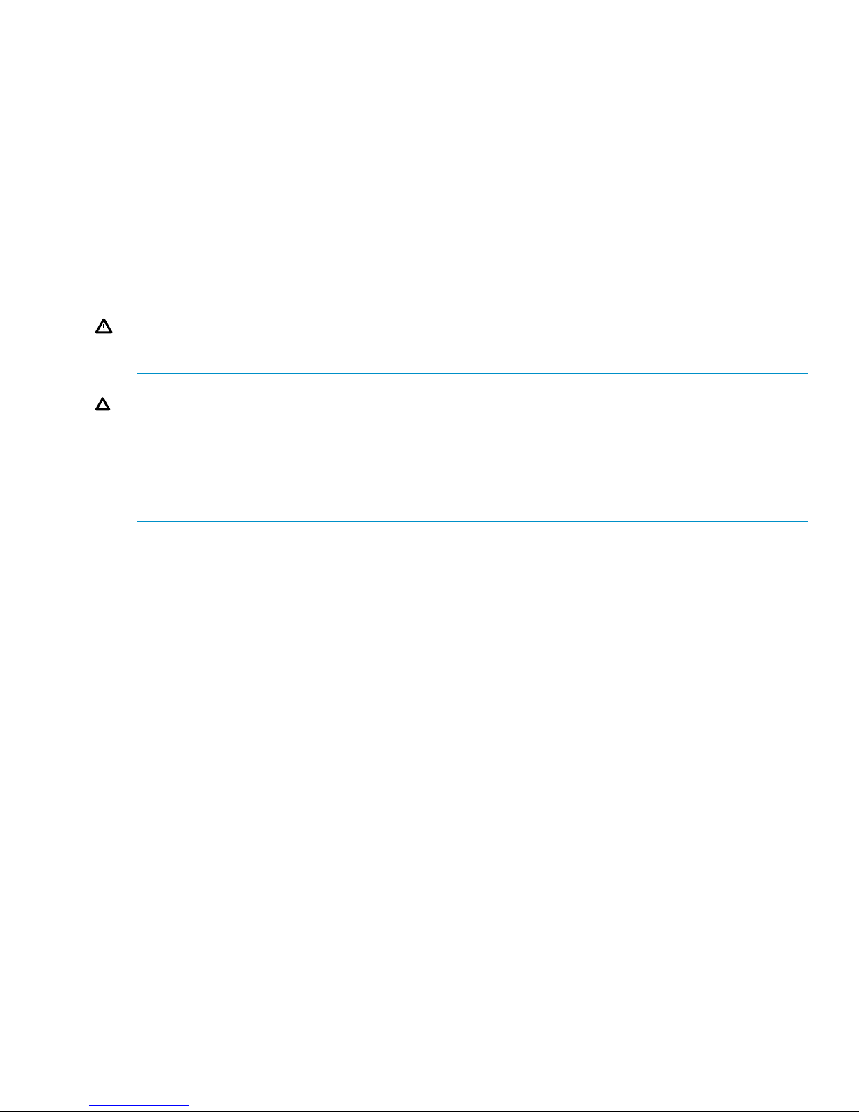
Attaching the rails
1. Position left and right rack rails at the desired 'U' position in the rack, adjust the rails to fit the
rack as needed (1, Figure 1 (page 4)).
About this document 3
Page 4
2. Secure rack rails to the front and back rack columns using screws. Make sure that the shoulders
of the screws fit inside the square or round holes of the rack (2, Figure 1).
NOTE: If installing rails in a square hole rack, use larger-sized shoulder screws and pins for
mounting. If installing rails in a round hole rack, use smaller-sized shoulder screws and pins for
mounting.
Figure 1 Secure rack rails
4 Attaching the rails
Page 5
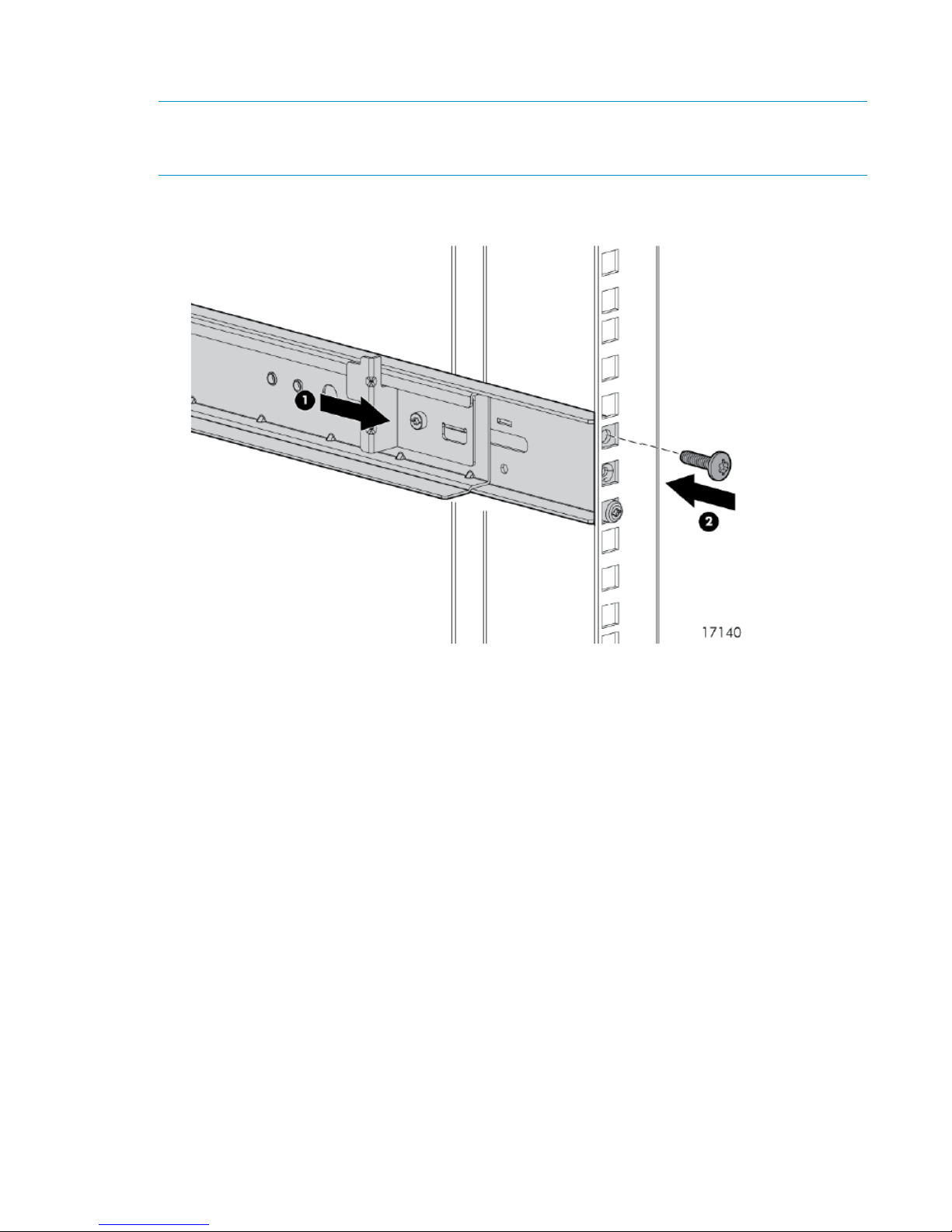
Installing the disk enclosure
1. Slide the device into position on the rails (1, Figure 2 (page 5)) and then tighten the thumbscrews
(2) on the front of the device to secure the device to the rack.
Figure 2 Secure disk enclosure to rack
NOTE: The rear ends of the rails have a CTO bracket that must engage the device chassis to
secure the rear of the chassis to the rails.
Figure 3 Engaging CTO bracket
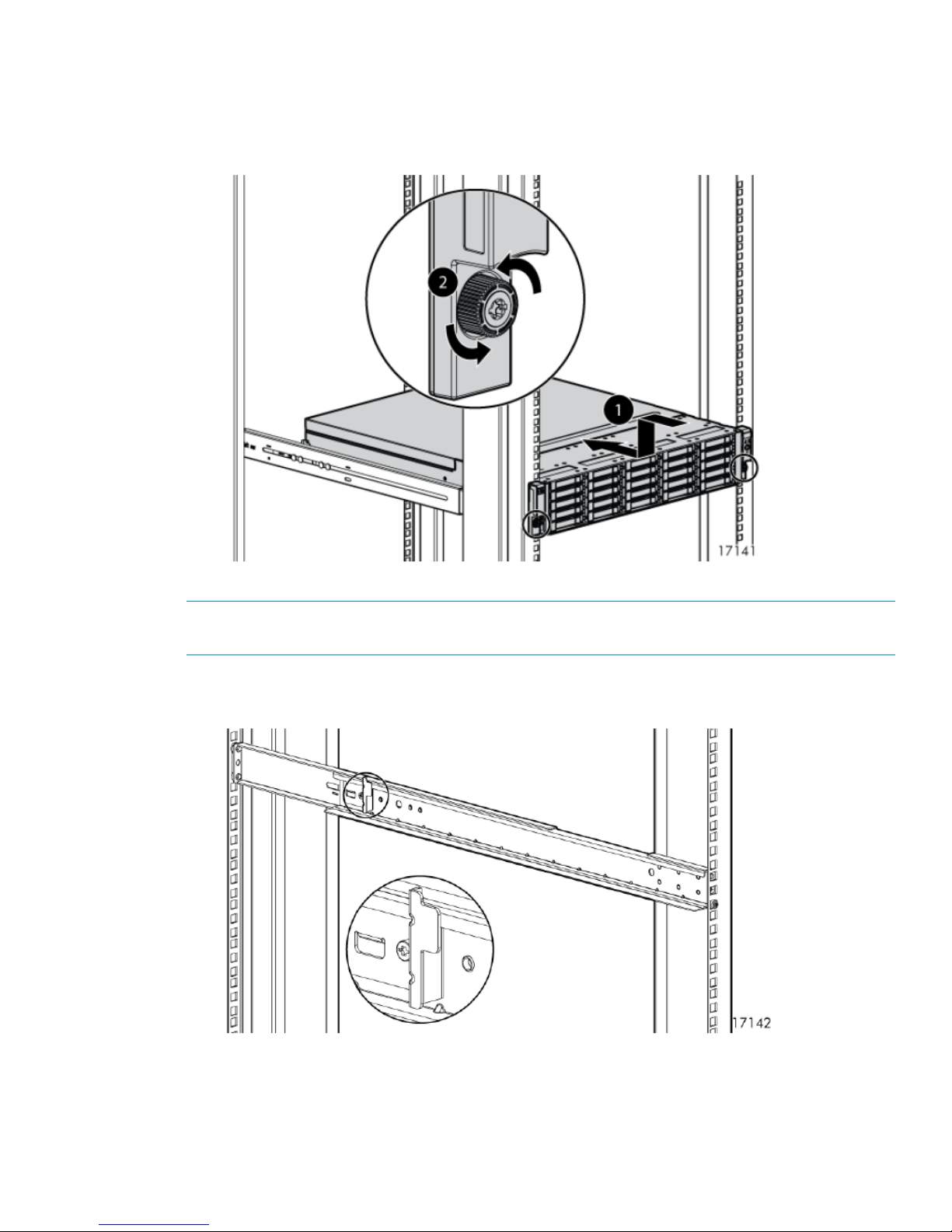
2. When cabling the device, use holes provided in the rear rack rails, install tie wraps, and route
external cable as required.
Installing the disk enclosure 5
Page 6
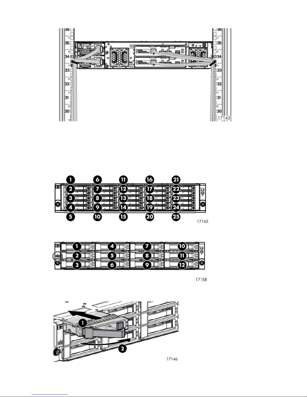
Figure 4 Installing tie wraps and routing cables
3. Populate the enclosure with available disk drives (not included with this kit). Start with the lowest
number in for the M6625, and Figure 7 (page 6) for the M6612, and continue in order until
you have inserted the desired number. If installing multiple disk enclosures, balance the quantity
and sizes of disk drives between the enclosures as evenly as possible.
Figure 5 M6625 disk drive numbering
Figure 6 M6612 disk drive numbering
Figure 7 Inserting a disk drive
6 Installing the disk enclosure
Page 7

4. Insert drive blank into any slots without a disk drive. Push the drive blank until you detect a click.
Figure 8 Inserting a drive blank
Cabling the enclosure
Two methods are described for cabling a new disk enclosure. The online method allows a disk enclosure
to be added to a powered, operational array. The offline method describes cabling an array that has
been powered down. The offline method is preferred if downtime is available.
Consider the following guidelines when connecting disk enclosures to the P6300/P6500 EVA:
• The power cords are supplied in two different colors should you decide to use the colors to denote
sides of the rack. For example, you can locate all gray power cords on the left side of the rack,
and all black power cords on the right side.
• The P6300 EVA supports a maximum of 10 disk enclosures. The P6500 supports a maximum of
20 disk enclosures. Due to space constraints, the diagrams in this document show a minimum
number of disk enclosures. However, you can follow these instructions and diagrams for any
configuration.
• In general, when cabling, the P1 port on the I/O module receives input from another I/O module
or controller, and the P2 port is used for output to another I/O module or controller.
• Always connect cables to the same colored port (green port to green port, red port to red port).
The cables shown in this document are colored green and red to easily identify connections.
• In these diagrams, the dashed lines indicate how the cabling changes when a disk enclosure is
added.
• In the offline procedure, I/O module A is cabled first and then I/O module B is cabled. However,
either I/O module can be cabled first when power is not applied to the array.
• The P6300 EVA is only available in a multiproduct rack configuration, which is designed to
maximize space (controller and disk enclosures at the bottom of the rack and non-storage hardware
above the enclosures). You may need to reconfigure rack space before adding disk enclosures.
In the multiproduct configuration, disk enclosures are added above the controller enclosure.
Cabling the enclosure 7
Page 8

Cabling the P6300 EVA enclosure while offline
1. Power down the array.
Figure 9 (page 8) shows the cabling for an array with one P6300 EVA controller enclosure and
two disk enclosures.
Figure 9 Cabling for preexisting P6300 EVA
2. Figure 10 (page 8) shows the cabling when two disk enclosures are added to the array. Unplug
the cable between DP-B on controller 1 and I/O module B port P2 of the existing disk enclosure
at the bottom of the rack. Connect the cable from DP-B on controller 1 to I/O module B port P2
on the newly installed disk enclosure closest to the controller enclosure (1, Figure 10 (page 8)).
Figure 10 Adding disk enclosures to the P6300 EVA
8 Cabling the enclosure
Page 9

Table 1 Adding disk enclosures to the P6300 EVA callouts
DescriptionCallout
Connects controller 1, DP-B to newly installed I/O module B, port P2 (closest to controller enclosure)1
Connects I/O module B, port P2 to I/O module B, port P1 between newly installed disk enclosures2
3
Connects existing I/O module B, port P2 (bottom of rack) to topmost, newly installed I/O module B,
port P1
Connects topmost, newly installed I/O module A, port P1 to bottom existing I/O module A, port P24
Connects I/O module A, port P2 to I/O module A, port P1 between newly installed disk enclosures5
Connects controller 2, DP-A to newly installed I/O module A, port P2 (closest to controller enclosure)6
3. Using a cable provided in your kit, plug one end into the P1 port on I/O module B of the newly
installed disk enclosure closest to the controller enclosure and plug the other end into the P2 port
of I/O module B of the other newly installed disk enclosure above it (2, Figure 10).
4. Using a long cable, plug one end into the P2 port of I/O module B on the existing disk enclosure
at the bottom of the rack and plug the other end into the P1 port of I/O module B on the topmost,
newly installed disk enclosure (3, Figure 10).
5. Unplug the cable between DP-A on controller 2 and I/O module A P2 on the existing disk enclosure
at the bottom of the rack. Using a long cable, connect the P1 port of I/O module A on the topmost,
newly installed disk enclosure to the P2 port of I/O module A on the existing disk enclosure at
the bottom of the rack (4, Figure 10).
6. Connect the P2 port of I/O module A on the topmost, newly installed disk enclosure to the P1
port of I/O module A on the other newly installed disk enclosure directly below it (5, Figure 10).
7. Plug one end of a cable into DP-A of controller 2 and plug the other end into the P2 port of I/O
module A on the newly installed disk enclosure directly above the controller enclosure (6,
Figure 10).
8. Using a power cord provided in your kit, plug one end into a disk enclosure power supply and
the other end into a rack power distribution module.
9. With the remaining power cord, connect the other power supply to a rack power distribution
module.
10. Press the Power On/Standby button on the power UID bezel (located at the rear of the disk
enclosure) and hold it down long enough to power up the installed enclosure.
11. Power on any other disk enclosures attached to the array and visually check that the enclosures
power on without errors. Wait at least one minute after all the enclosures are powered on for the
drives to spin up and stabilize.
12. Power on the controller enclosure by pressing the power button on the power UID bezel until the
enclosure responds (it may take up to 10 seconds for the controller enclosure to power on). Wait
five minutes for the array to stabilize.
Cabling the enclosure 9
Page 10

13. Verify the status of the newly installed disk enclosure:
a. Open HP P6000 Command View.
b. Navigate to the newly added disk enclosure within the Hardware folder in the navigation
pane and select it. The Disk Enclosure Properties window opens.
c. Select the I/O tab and verify that the Operational state for both ports on both I/O modules
is Good.
NOTE: If the newly added disk enclosure is at a different I/O module firmware version,
the overall operational state will display Loading firmware. The state will remain as Loading
firmware until the other I/O module is connected. At that point, the I/O module firmware
will be upgraded.
14. Verify that I/O modules A and B on the added enclosure have been assigned a unique (but not
necessarily sequential) index number.
Cabling the P6300 EVA enclosure while online
Figure 9 (page 8) shows the cabling for an array with one P6300 EVA controller enclosure and two
disk enclosures.
NOTE: You can only add one disk enclosure online at a time.
1. Using a power cord provided in your kit, plug one end into the disk enclosure power supply and
the other end into a rack power distribution module. You will briefly hear a rush of air as power
is applied, and the LEDs on the power UID flash. The power UID standby switch LED remains
amber.
2. With the remaining power cord, connect the other power supply to a rack power distribution
module. The power UID power switch LED turns green. The I/O module index number will likely
display 00, but if not, ignore the index number at this time.
3. Figure 11 (page 11) shows the cabling when one disk enclosure is added to the array. Unplug
the cable between DP-B on controller 2 and I/O module B port 1 on the nearest disk enclosure
below the controller enclosure. Connect the cable from DP-B on controller 2 to I/O module B port
P1 on the newly installed disk enclosure (1, Figure 11 (page 11)).
10 Cabling the enclosure
Page 11

Figure 11 Adding a disk enclosure to the P6300 EVA
Table 2 Adding a disk enclosure to the P6300 EVA callouts
DescriptionCallout
Connects controller 2, DP-B to newly installed I/O module B port P11
Connects existing I/O module B port P1 to newly installed I/O module I/O module B, port P22
Connects controller 1, DP-A to newly installed I/O module A port P13
Connects existing I/O module A, port P1 to newly installed I/O module A, port P24
4. Using a long cable, plug one end into port P1 of I/O module B that was unplugged in the previous
step and plug the other end into port P2 of I/O module B on the newly installed disk enclosure
(2, Figure 11).
In steps 3 and 4, connections to I/O module B are made first. However, either I/O module can
be cabled first as long as the other I/O module ports are not unplugged until cabling is complete
on the first I/O module and you have completed step 6. This enables the controllers to redundantly
manage storage while the cables are briefly pulled and reconnected on one side.
NOTE: With only one I/O module from the newly added enclosure cabled to the array, there
will be HP P6000 Command View warnings that indicate disk drives in the system are only
connected on one of the redundant loops. This is to be expected, and the warnings should clear
as soon as the other I/O module is connected.
5. Once you connect one I/O module (for example, B), verify the status of the I/O module B ports
and the presence of the newly added disk enclosures before you connect the other I/O modules
(in this example, A). Failure to complete this verification could result in potential loss of data access
for an extended period of time. Complete the following steps to verify:
a. Open HP P6000 Command View.
b. Navigate to the newly added disk enclosure within the Hardware folder in the navigation
pane and select it. The Disk Enclosure Properties window opens.
c. Select the I/O tab.
Cabling the enclosure 11
Page 12

d. For the I/O module that you connected, check that the overall operational state and the
connection and operational states for each port displays Good. The other I/O module that
is not yet connected will display Not installed for the overall operational state and Not
available for each port operational state.
NOTE: If the newly added disk enclosure is at a different I/O module firmware version,
the overall operational state will display Loading firmware. The state will remain as Loading
firmware until the other I/O module is connected. At that point, the I/O module firmware
will be upgraded.
e. Once you connect the other I/O module, repeat Step 5.b through Step 5.d to verify that I/O
module's status.
6. Complete the connections to I/O module A:
a. Unplug the cable between DP-A on controller 1 and I/O module A port P1 on the nearest
disk enclosure below the controller enclosure. Connect the cable from DP-A on controller 1
to I/O module A port P1 on the newly installed disk enclosure (3, Figure 11).
b. Using a long cable, plug one end into port P1 of I/O module A on the existing disk enclosure
below and closest to the controller enclosure and I/O module A port P2 on the newly installed
disk enclosure (4, Figure 11).
7. Repeat step 5 to verify the I/O module A connections.
8. Verify that I/O modules A and B on the added enclosure have been assigned a unique (but not
necessarily sequential) index number.
12 Cabling the enclosure
Page 13

Cabling the P6500 EVA enclosure while offline
Adding below the controller enclosure
1. Power down the array and existing disk enclosures.
Figure 12 (page 13) shows the cabling for an array with one P6500 EVA controller enclosure
and four disk enclosures. With the P6500 EVA, disk enclosure are balanced as evenly as possible
above and below the controller enclosures. Additionally, the controller enclosure and disk
enclosures are connected using Y-cables. The Y-cables enable each controller port to act as two
ports. For example, the DP-A port has both a DP-1 cable and a DP-2 cable.
Figure 12 Cabling for preexisting P6500 EVA
2. Figure 13 (page 14) shows the cabling when another disk enclosure is added below the controller
enclosure.
Unplug the DP-1 cable from I/O module A port P1 of the existing disk enclosure nearest the newly
installed disk enclosure and plug it into port P1 of I/O module A of the newly installed disk
enclosure (1, Figure 13 (page 14)).
Cabling the enclosure 13
Page 14

Figure 13 Adding a disk enclosure below the P6500 EVA
Table 3 Adding a disk enclosure below the P6500 EVA callouts
DescriptionCallout
1
3
Connects installed I/O module A, port P1 (below controller) to controller 1, port DP-A (using the DP-1
cable)
Connects installed I/O module A, port P2 (below controller) to existing I/O module, port P12
Connects installed I/O module B, port P1 (below controller) to controller 2, port DP-B (using the DP-1
cable)
Connects installed I/O module B, port P2 (below controller) to existing I/O module B, port P14
3. Using a cable provided in your kit, plug one end into the P1 port of I/O module A (below the
controller enclosure) that was unplugged in the previous step and plug the other end into port P2
of I/O module A of the newly installed disk enclosure (2, Figure 13).
4. Complete the connections to I/O module B of the newly installed disk enclosure (below the
controller enclosure). The result is the DP-1 cable on port P1 of I/O module B of the disk enclosure
previously closest to the controller enclosure is moved to port P1 of I/O module B of the newly
installed disk enclosure (3, Figure 13). Also, a new cable is installed between I/O module B port
P1 of the existing disk enclosure and I/O module B port P2 of the newly installed disk enclosure
(4, Figure 13).
5. Follow steps 8–14 in “Cabling the P6300 EVA enclosure while offline” (page 8) to complete
the installation.
14 Cabling the enclosure
Page 15

Adding above the controller enclosure
Complete the following procedure to add a disk enclosure above the controller enclosure.
1. Figure 14 (page 15) shows the cabling when a disk enclosure is added above the controller
enclosure. Unplug the DP-2 cable from I/O module port P1 of the existing disk enclosure nearest
the newly installed disk enclosure and plug it into port P1 of I/O module A of the newly installed
disk enclosure (1, Figure 14 (page 15)).
Figure 14 Adding a disk enclosure above the P6500 EVA
Table 4 Adding a disk enclosure above the P6500 EVA callouts
DescriptionCallout
Connects installed I/O module A, port P1 to controller 1, port DP-A (using the DP-2 cable)1
Connects installed I/O module A, port P2 (above controller) to existing I/O module A, port P12
3
Connects installed I/O module B, port P1 (above controller) to controller 2, port DP-B (using the DP-2
cable)
Connects installed I/O module B, port P2 (above controller) to existing I/O module B, port P14
Cabling the enclosure 15
Page 16

2. Using a cable provided in your kit, plug one end into the P1 port of I/O module A (above the
controller enclosure) that was unplugged in the previous step and plug the other end into port P2
of I/O module A of the newly installed disk enclosure (2, Figure 14).
3. Complete the connections to I/O module B of the newly installed disk enclosure (above the
controller enclosure). The result is the DP-2 cable on port P1 of I/O module B of the disk enclosure
previously at the top is moved to port P1 of I/O module B of the newly installed disk enclosure
(3, Figure 14). Also, a new cable is installed between I/O module B P1 of the existing disk
enclosure and I/O module B port P2 of the newly installed disk enclosure (4, Figure 14).
4. Follow steps 8–14 in “Cabling the P6300 EVA enclosure while offline” (page 8) to complete
the installation.
Cabling the P6500 EVA enclosure while online
Figure 12 (page 13) shows the cabling for an array with one P6500 EVA controller enclosure and
four disk enclosures. With the P6500 EVA, disk enclosure are balanced as evenly as possible above
and below the controller enclosure. Additionally, the controller enclosure and disk enclosures are
connected using Y-cables. The Y-cables enable each controller port to act as two ports. For example,
the DP-A port has both a DP-1 cable and a DP-2 cable.
Figure 13 (page 14) shows the cabling when another disk enclosure is added to the array below the
controller enclosure. Figure 14 (page 15) shows the cabling when a disk enclosure is added to the
array above the controller enclosure. The remaining steps in this procedure apply when the disk
enclosure is added below the controller enclosure. However, you can adapt these steps for the addition
above the controller enclosure.
Once you place the new disk enclosures in the rack, complete the following procedure to add each
new disk enclosure online.
NOTE: You can only add one disk enclosure online at a time.
1. Using a power cord provided in your kit, plug one end into the disk enclosure power supply and
the other end into a rack power distribution module. You will briefly hear a rush of air as power
is applied, and the LEDs on the power UID flash. The power UID standby switch LED remains
amber.
2. With the remaining power cord, connect the other power supply to a rack power distribution
module. The power UID power switch LED turns green. The I/O module index number will likely
display 00, but if not, ignore the index number at this time.
3. Unplug the DP-1 cable from I/O module A port P1 of the existing disk enclosure nearest the newly
installed disk enclosure and plug it into port P1 of I/O module A of the newly installed disk
enclosure (1, Figure 13 (page 14)).
4. Using a cable provided in your kit, plug one end into the P1 port of I/O module A (below the
controller enclosure) that was unplugged in the previous step and plug the other end into port P2
of I/O module A of the newly installed disk enclosure (2, Figure 13). Note the enclosure ID shown
on the I/O module to determine which one to observe with HP P6000 Command View.
In this step, connections to I/O module A are made first. However, either I/O module can be
cabled first as long as the other I/O module ports are not unplugged until cabling is complete on
the first I/O module and you have completed step 5. This enables the controllers to redundantly
manage storage while the cables are briefly pulled and reconnected on one side.
NOTE: With only one I/O module from the newly added enclosure cabled to the array, there
will be HP P6000 Command View warnings that indicate disk drives in the system are only
connected on one of the redundant Fibre Channel loops. This is to be expected, and the warnings
should clear as soon as the other I/O module is connected.
5. Once you connect one I/O module (for example, A), verify the status of the I/O module A ports
and the presence of the newly added disk enclosure (using the enclosure ID noted in the previous
step) before you connect the other I/O module (in this example, B). Failure to complete this
16 Cabling the enclosure
Page 17

verification could result in potential loss of data access for an extended period of time. Complete
the following steps to verify:
a. Open HP P6000 Command View.
b. Navigate to the newly added disk enclosure within the Hardware folder in the navigation
pane and select it. The Disk Enclosure Properties window opens.
c. Select the I/O tab.
d. For the I/O module that you connected, check that the overall operational state and the
connection and operational states for each port displays Good. The other I/O module that
is not yet connected will display Not installed for the overall operational state and Not
available for each port operational state.
NOTE: If the newly added disk enclosure is at a different I/O module firmware version,
the overall operational state will display Loading firmware. The state will remain as Loading
firmware until the other I/O module is connected. At that point, the I/O module firmware
will be upgraded.
e. Once you connect the other I/O module, repeat Step 5.b through Step 5.d to verify that I/O
module's status.
6. Complete the connections to I/O module B of the newly installed disk enclosure (below the
controller enclosure). The result is the cable on port P1 of I/O module B of the disk enclosure
previously closest to the controller enclosure is moved to port P1 of I/O module B of the newly
installed disk enclosure (3, Figure 13). Also, a new cable is installed between I/O module B port
P1 of the preexisting disk enclosure and I/O module B port P2 of the newly installed disk enclosure
(4, Figure 13).
7. Verify that I/O modules A and B on the added enclosure have been assigned a unique (but not
necessarily sequential) index number.
Cabling the enclosure 17
 Loading...