

Page 1

HP P10000 3PAR Storage System Physical
Planning Manual
Abstract
This manual provides information that is useful for planning and preparing for the installation of HP 3PAR Storage Systems.
Use this document in conjunction with the HP 3PAR Systems Assurance and Pre-Installation Site Planning Guide that details
specific system configuration and installation information for your storage system and operating site. The information in this
manual is intended for use by HP customers, in conjunction with the advice and assistance of an HP Sales Representative or
Systems Engineer, for the purpose of planning an HP 3PAR Storage System installation. The installation of HP 3PAR Storage
Systems and hardware components is to be completed by qualified technicians who are authorized by HP. Authorized technicians
include HP Field Engineers, Value Added Resellers (VARs), and authorized third-party field technicians.
HP Part Number: QL226-96013
Published: June 2011
Page 2

© Copyright 2011 Hewlett-Packard Development Company, L.P.
The information contained herein is subject to change without notice. The only warranties for HP products and services are set forth in the express
warranty statements accompanying such products and services. Nothing herein should be construed as constituting an additional warranty. HP shall
not be liable for technical or editorial errors or omissions contained herein.
Acknowledgments
Intel®, Itanium®, Pentium®, Intel Inside®, and the Intel Inside logo are trademarks or registered trademarks of Intel Corporation or its subsidiaries
in the United States and other countries.
Microsoft®, Windows®, Windows® XP, and Windows NT® are U.S. registered trademarks of Microsoft Corporation.
Adobe® and Acrobat® are trademarks of Adobe Systems Incorporated.
Java and Oracle are registered trademarks of Oracle and/or its affiliates.
UNIX® is a registered trademark of The Open Group.
Warranty
WARRANTY STATEMENT: To obtain a copy of the warranty for this product, see the warranty information website:
http://www.hp.com/go/storagewarranty
AIX is a registered trademark of the IBM Corporation
Cygwin is a trademark of Red Hat, Inc.
HP-UX is a registered trademark of the Hewlett-Packard Company.
Linux is a registered trademark of Linus Torvalds.
Microsoft Windows, and Windows NT are either registered trademarks or trademarks of Microsoft Corporation.
NEMA is a registered trademark of National Electrical Manufacturers Association.
Panasonic is a registered trademark of Matsushita Electric Industrial Co., Inc.
SecureCRT is a registered trademark of VanDyke Software, Inc.
Sun, Solaris, and Java are trademarks of Sun Microsystems, Inc.
UL is a registered trademark of Underwriters Laboratories Inc.
WinZip is a registered trademark of WinZip Computing, Inc.
All other trademarks and registered trademarks are owned by their respective owners.
Federal Communications Commission Radio Frequency Interference Statement
WARNING: Changes or modifications to this unit not expressly approved by the party responsible for compliance could void the user’s authority
to operate the equipment.
This device complies with Part 15 of FCC Rules. Operation is subjected to the following two conditions (1) this device may not cause harmful
interference, and (2) this device must accept any interference received, including interference that may cause undesired operation.
This equipment has been tested and found to comply with the limits for a Class A digital device, pursuant to Part 15 of the FCC rules. These limits
are designed to provide reasonable protection against harmful interference when the equipment is operated in a commercial environment. This
equipment generates, uses, and can radiate radio frequency energy and, if not installed and used in accordance with the instruction manual, may
cause harmful interference to radio communications. Operation of this equipment in a residential area is likely to cause harmful interference in which
case the user will be required to correct the interference at his own expense.
Canadian Compliance Statement
This ClassA digital apparatus meets all requirements of the Canadian Interference-Causing Equipment Regulations.
Cet appareil numérique de la classe A respecte toutes les exigences du Règlement sur le matérial brouilleur du Canada.
Page 3

Contents
1 Introduction...............................................................................................6
Related Documentation..............................................................................................................6
Typographical Conventions........................................................................................................6
Advisories................................................................................................................................6
2 System Components and Specifications.........................................................8
HP 3PAR Storage System Components.........................................................................................8
V400/V800 Storage System Specifications................................................................................10
Physical Specifications........................................................................................................10
Capacity Specifications......................................................................................................10
Power and Heat Specifications.................................................................................................11
Environmental Specifications....................................................................................................12
Cable Specifications...............................................................................................................13
3 General Site Planning...............................................................................14
General Planning...................................................................................................................14
Customer Responsibilities....................................................................................................14
Planning for Installation......................................................................................................14
Preparing a Pre-Installation Site Planning Guide.....................................................................15
Storage System Cabinet Shipping Containers.............................................................................15
Acclimatization.......................................................................................................................17
4 Structural/Environmental Considerations......................................................18
General Information................................................................................................................18
Establishing the Proper Foundation............................................................................................18
Benefits of Raised Floors.....................................................................................................18
Raised Floor Requirements...................................................................................................18
Weight and Pressure Loads.................................................................................................20
Tile Cutout Specifications....................................................................................................20
Anchoring Dimensions for Storage Systems............................................................................21
Additional Flooring Recommendations..................................................................................23
Hot-Aisle/Cold-Aisle Cooling Layout.....................................................................................24
Providing for Service Access.....................................................................................................25
Meeting Environmental Conditions............................................................................................25
Maintaining the Optimal Temperature..................................................................................26
Air Supply and Flow...........................................................................................................27
Air Cleanliness..................................................................................................................27
5 Power Requirements..................................................................................29
Powering HP P10000 3PAR Storage Systems..............................................................................29
Power Distribution Units (PDUs)............................................................................................31
Battery Modules................................................................................................................33
Power Cord Connections.....................................................................................................33
Electrical Requirements and Limitations......................................................................................34
Power and Heat Specifications.................................................................................................34
Power Quality........................................................................................................................35
Voltage and Frequency Tolerance.............................................................................................36
Voltage Spikes.......................................................................................................................36
Electrostatic Discharge.............................................................................................................36
Branch Circuits.......................................................................................................................36
Emergency Power Control........................................................................................................36
Redundant Power....................................................................................................................36
Contents 3
Page 4

6 Network, Cabling and Connectivity............................................................41
Planning Network Access........................................................................................................41
Supported Network Topologies............................................................................................41
Shared Network...........................................................................................................41
Private Network............................................................................................................42
TCP/IP Port Assignments..........................................................................................................42
Controller Node Connections...................................................................................................45
Required Cables.....................................................................................................................46
External Cable Connections.....................................................................................................46
Internal Cable Connections......................................................................................................47
Cable Routing Options............................................................................................................47
Service Processor Connections..................................................................................................48
Connecting the Service Processor.........................................................................................49
A Regulatory compliance notices...................................................................50
Regulatory compliance identification numbers............................................................................50
Federal Communications Commission notice..............................................................................50
FCC rating label................................................................................................................50
Class A equipment........................................................................................................50
Class B equipment........................................................................................................50
Declaration of Conformity for products marked with the FCC logo, United States only.................51
Modification.....................................................................................................................51
Cables.............................................................................................................................51
Canadian notice (Avis Canadien).............................................................................................51
Class A equipment.............................................................................................................51
Class B equipment.............................................................................................................51
European Union notice............................................................................................................51
Japanese notices....................................................................................................................52
Japanese VCCI-A notice......................................................................................................52
Japanese VCCI-B notice......................................................................................................52
Japanese VCCI marking.....................................................................................................52
Japanese power cord statement...........................................................................................52
Korean notices.......................................................................................................................52
Class A equipment.............................................................................................................52
Class B equipment.............................................................................................................52
Taiwanese notices...................................................................................................................53
BSMI Class A notice...........................................................................................................53
Taiwan battery recycle statement..........................................................................................53
Turkish recycling notice............................................................................................................53
Vietnamese Information Technology and Communications compliance marking...............................53
Recycling notices....................................................................................................................53
English recycling notice......................................................................................................53
Bulgarian recycling notice...................................................................................................54
Czech recycling notice........................................................................................................54
Danish recycling notice.......................................................................................................54
Dutch recycling notice.........................................................................................................54
Estonian recycling notice.....................................................................................................54
Finnish recycling notice.......................................................................................................55
French recycling notice.......................................................................................................55
German recycling notice.....................................................................................................55
Greek recycling notice........................................................................................................56
Hungarian recycling notice.................................................................................................56
Italian recycling notice........................................................................................................56
Latvian recycling notice.......................................................................................................56
Lithuanian recycling notice..................................................................................................57
4 Contents
Page 5

Polish recycling notice.........................................................................................................57
Portuguese recycling notice.................................................................................................57
Romanian recycling notice..................................................................................................57
Slovak recycling notice.......................................................................................................58
Spanish recycling notice.....................................................................................................58
Swedish recycling notice.....................................................................................................58
Battery replacement notices.....................................................................................................58
Dutch battery notice...........................................................................................................58
French battery notice..........................................................................................................59
German battery notice........................................................................................................59
Italian battery notice..........................................................................................................60
Japanese battery notice......................................................................................................60
Spanish battery notice........................................................................................................61
Contents 5
Page 6
1 Introduction
This manual provides information that is useful for planning and preparing for the installation of
HP 3PAR Storage Systems. Use this document in conjunction with the 3PAR Systems Assurance
and Pre-Installation Site Planning Guide that details specific system configuration and installation
information for your storage server and operating site.
Physical planning and preparation are essential to a successful installation. If you have concerns
or issues not specifically addressed in this manual, (or your systems planning document), contact
your local HP 3PAR Sales Representative or HP 3PAR Systems Engineer.
NOTE: The InServ Storage Server has been rebranded as HP 3PAR Storage System. There are
instances in this document where menu items and command output refer to the HP 3PAR Storage
System as InServ or InServ Storage Server.
Related Documentation
The following documents also provide information related to HP 3PAR Storage Systems and the
InForm® Operating System that might be useful in preparing to install, configure and operate the
equipment.
Table 1 Related Documentation
Read the…For information about…
HP 3PAR InForm OS Concepts GuideStorage system concepts and terminology
HP 3PAR InForm Management Console On-Line HelpUsing the InForm Management Console to configure and
administer HP 3PAR Storage Systems
HP 3PAR InForm OS CLI Administrator’s ManualUsing the InForm Command Line Interface (CLI) to configure
and administer HP 3PAR Storage Systems
HP 3PAR InForm OS Command Line Interface ReferenceCLI commands and their usage
Typographical Conventions
The following typographical conventions are used in this guide:
Table 2 Typographical Conventions
ExampleMeaningTypeface
Enter your system name in the Value
box and click OK.
Used for dialog box elements such as
titles and button labels.
ABCDabcd
Found < 12 > 73G disks.Used for file names, paths, and screen
output, and for text you are to enter.
ABCDabcd
Enter cli at the Windows command
prompt.
cli% removevv VV1Used to contrast your input with system
output.
ABCDabcd
Removing vv VV1.
[root@(systemID-nodeID)root]
To continue Enter your system
name ==> systemname
Used for variables in file names,
paths, and screen output, and
variables in user input.
ABCDabcd
ABCDabcd
Advisories
Before installing an HP 3PAR Storage Systems, consult the Agency Compliance Statements at the
end of this book, to obtain important safety information.
6 Introduction
Page 7

To avoid injury to people or damage to data and equipment, be sure to observe the cautions and
warnings in this guide. Always be careful when operating any electrical equipment.
The following alerts appear throughout this guide:
WARNING! Warnings alert you to actions that can cause injury to people or irreversible damage
to data or the operating system.
CAUTION: Cautions alert you to actions that can cause damage to equipment, software, or data.
NOTE: Notes are reminders, tips, or suggestions that supplement the information included in this
guide.
Advisories 7
Page 8

2 System Components and Specifications
This chapter provides detailed system specifications for the HP P10000 3PAR Storage Systems
and serves as a quick reference for other relevant specifications that are described in more detail
in other chapters of this manual.
HP 3PAR Storage System Components
HP 3PAR Storage Systems are designed around a cluster-based approach that incorporates
sophisticated data management and fault tolerance technologies that can meet the storage needs
of smaller sites and can easily be scaled for global organizations.
The HP P10000 3PAR Storage Systems are housed in a 2 meter (2M) cabinet and are comprised
of the following components:
• Controller Nodes are high-performance, data movement engines that provide the caching
capabilities and manage the flow of data in a storage system. The V400 Storage System can
accomodate two or four controller nodes while the V800 can accomodate two, four, six or
eight nodes.
• 3PAR Storage Server Backplane works in conjunction with the controller nodes to route data.
This passive, full-mesh backplane enables high-bandwidth and low-latency internal pathing
that supersedes bus-, switch-, and even InfiniBand-based architectures.
• Drive Chassis houses the drive cages that, in turn, contain the drive bays. Each drive bay can
accommodate a single drive magazine that holds an array of hard disk drives. These are
intelligent, compact, extremely dense storage units, where each is capable of holding a large
numbers of disk drives in a a small rack space (EIA-standard rack units).
• Fibre Channel adapters and FC-AL modules provide high speed routing of data and enable
granular and potentially massive connectivity to hosts and to the drive chassis.
• Service Processor provides the remote error detection and reporting capabilities that support
diagnostic and maintenance activities for storage systems. In general, one Service Processor
is required per storage system.
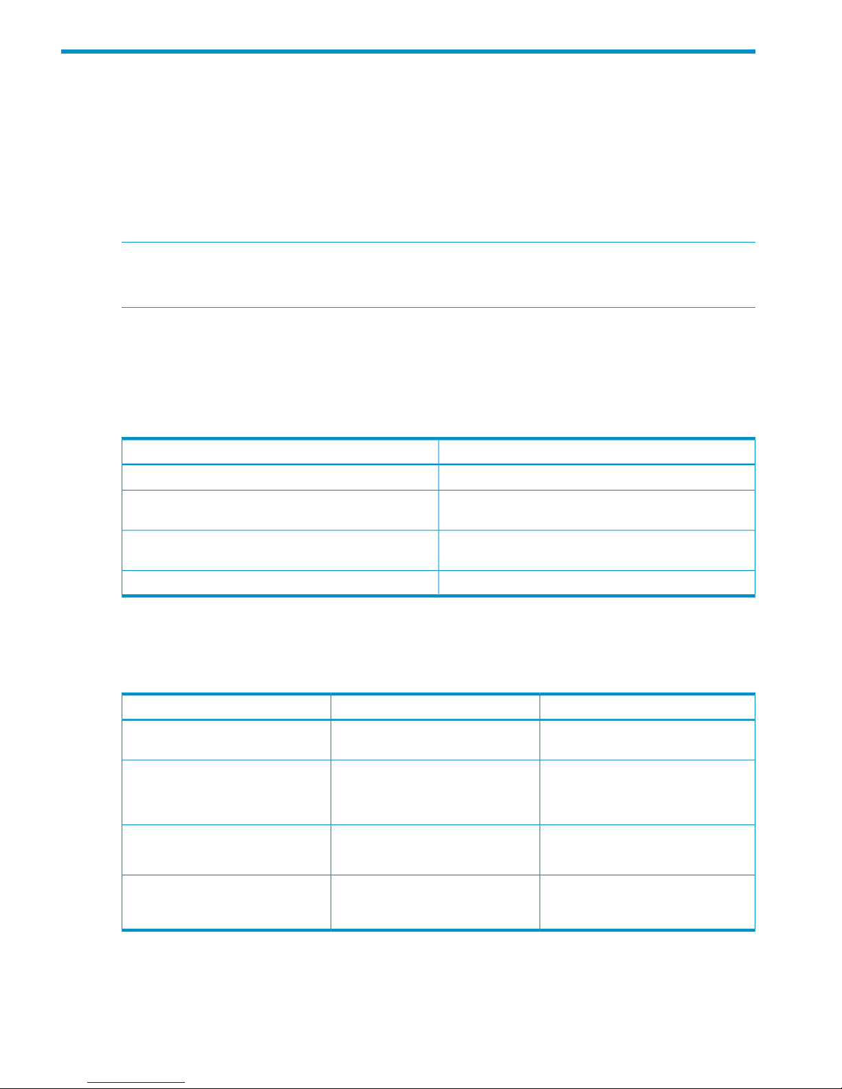
Figure 1 (page 9) and Figure 2 (page 9) show the front and rear views of a fully populated 2M
(40U) HP P10000 3PAR Storage System cabinet with the various components installed:
8 System Components and Specifications
Page 9
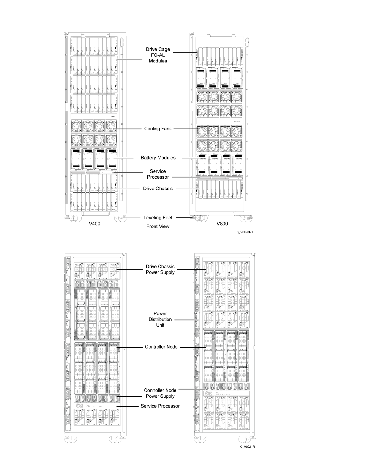
Figure 1 Front view of the HP P10000 3PAR Storage System
Figure 2 Rear View of the HP P10000 3PAR Storage System
HP 3PAR Storage System Components 9
Page 10

V400/V800 Storage System Specifications
The HP 3PAR V400 and V800 Storage Systems accommodate a maximum of up to four or eight
controller nodes, respectively. The maximum number of supported drive chassis varies according
to the number of controller nodes utilized by the system, the number and type of Fibre Channel
adapters that are installed.
Physical Specifications
The following table lists system specifications for the HP P10000 3PAR Storage Systems. These
specifications are subject to change without notice.
Table 3 V400/V800 Storage System Physical Specifications
V400/V800 Storage System Physical Specifications
2-Meter Cabinet
60 x 194.3 x 91.3 cm23.6 x 76.5 x 36 in.Dimensions (width x height x depth)
36 in. (91.44 cm) front and 30 in.
(76.2 cm) back
Service Clearance
195.5 kg439 lbs.Weight (not populated)
852.8 kg1,880 lbs.Maximum Weight (fully populated)
213.2 kg470 lbs.Maximum Weight per leveling foot
10.5 kg/sq. cm149.6 lbs/sq. in.Maximum Load per leveling Foot
Component Weights
296.7 kg654.1 lbs.V400 Base Configuration
338.9 kg747.1 lbs.V800 Base Configuration
22.5 kg49.6 lbs.2 Controller Nodes (fully populated)
81.6 kg180 lbs.Drive Chassis (fully populated)
6.0 kg13.3 lbs.Service Processor
Capacity Specifications
The following table lists system capacity and configuration details for the HP P10000 3PAR Storage
Systems.
Table 4 V400/V800 Storage System Capacity Specifications
V800V400Feature
2, 4, 6, or 82 or 4Number of controller nodes
64 GB with 2 nodes 128 GB with 4
nodes 192 GB with 6 nodes 256 GB
with 8 nodes
32/64 GB with 2 nodes 64/128 GB
with 4 nodes
Control Cache
128 GB with 2 nodes 256 GB with 4
nodes 384 GB with 6 nodes 512 GB
with 8 nodes
64/128 GB with 2 nodes 128/256
GB with 4 nodes
Data Cache
0-48 0-96 0-144 0-1920-48 0-96Host Ports
4-48 4-96 4-1924-48 4-96Host Ports GZ number
8-24 with 2 nodes 16-48 with 4 nodes
32-96 with 8 nodes
8-24 with 2 nodes 16-48 with 4 nodesFC Disk Ports
10 System Components and Specifications
Page 11

Table 4 V400/V800 Storage System Capacity Specifications (continued)
V800V400Feature
0-8 with 2 nodes 0-16 with 4 nodes
0-32 with 8 nodes
0-8 with 2 nodes 0-16 with 4 nodes10 GB /s iSCSI Host Ports
0-48 (2 node) 0-96 (4 node) 0-144 (6
node) 0-192 (8 node)
0-48 (2 node) 0-96 (4 node)Fibre Channel host ports (four-port
adapters)
1
0-32 10 Gb/s0-16 10 Gb/siSCSI host ports
16-1,92016-960Number of drives
1
2.3-1600 TB2.3-800 TBRaw capacity (approx.)
1
6,4003,200Architectural maximum number of
drives
RAID 0, 1, 5, 6, 10, 50RAID 0, 1, 5, 6, 10, 50RAID levels
2:1 - 8:12:1 - 8:1RAID 5 data to parity ratios
300 GB 15K FC, 600 GB 15K FC, 2
TB NL, 100 GB SSD, 200 GB SSD
300 GB 15K FC, 600 GB 15K FC, 2
TB NL, 100 GB SSD, 200 GB SSD
Drive capacities (GB’s approx.)
1
Number of drive chassis
2
2–482–24DC4
0.0530.053Energy consumption efficiency
3
1 Levels, ratios, and capacities all mixable within the same storage server. 1 GB=1,000,000,000 bytes.
2 A single drive chassis holds up to 40 drives in 4U of space within an EIA-standard rack.
3 Japan Green Law statement of compliance: The energy consumption efficiency value has been calculated per requirements
for Category-G Magnetic Disk Drive Units by dividing the power consumption, measured according to the definition
in the Law Concerning the Rational Use of Energy, by the storage capacity defined in the Energy Conservation Law.
The efficiency value is based on a host-maximized V800 configuration using 600GB drives.
Power and Heat Specifications
The following table lists the electrical power requirements for the HP P10000 3PAR Storage Systems.
Table 5 HP P10000 3PAR Storage System Power Requirements per Cabinet
2 Meter Cabinet
9,984
1
Max. Watts per Cabinet (fully
populated)
34,075Max. BTUs/hour per cabinet (fully
populated)
200 - 240Input Voltage (VAC)
50 - 60Frequency (Hz)
30A per PDU (de-rated to 24A)Circuit Breaker Max
200Drive Chassis (no magazines)
(4) L6-30P Plug (North America
and Japan) (4) IEC-60309 Plug
(EU and Korea)
Power Connectors
IdleTransactional
2
Node Pair (fully populated)
630705Watts
2,1502,406BTUs/hour (fully populated)
Power and Heat Specifications 11
Page 12
Table 5 HP P10000 3PAR Storage System Power Requirements per Cabinet (continued)
200200Drive Chassis (no magazines)
Drive Magazine
3
4 x 100 GB SSD Drive Magazine
5.59.8Watts
1933BTUs/hour
4 x 200 GB SSD Drive Magazine
710.3Watts
2435BTUs/hour
4 x 300 GB FC Drive Magazine
5775Watts
195256BTUs/hour
4 x 600 GB FC Drive Magazine
6576Watts
222258BTUs/hour
4 x 2 TB NL Drive Magazine
3862Watts
131211BTUs/hour
Service Processor
317Watts
1,082 BTUs/hr.BTUs/hour (fully populated)
1 Theoretical maximum based on branch circuit capacity.
2 Under maximum load.
3 Up to 10 drive magazines (40 drives) per drive chassis.
NOTE: Refer to “Power Requirements” (page 29) for complete details.
Environmental Specifications
The following table lists the environmental specifications for the HP P10000 3PAR Storage Systems.
Table 6 Environmental Specifications for the HP P10000 3PAR Storage System
ValueSpecification
0 –10,000 ft (3,048 m) 0 –40,000 ft (12,192 m)Altitude Operating Nonoperating
50 –104° F (10–40° C) 0–3,000 ft (914.4 m) 50 –95° F
(10 –35° C) 3,000–10,000 ft (914–3,048 m) –40 –203°
F (–40– 95° C) 0–40,000 ft (0–12,192 m)
Ambient temperature Operating Nonoperating
18° F/hr (10° C/hr) 18° F/hr (10° C/hr)Temperature gradient Operating Nonoperating
20 – 80 percent noncondensing, maximum gradient 10
percent per hour
Relative humidity
12 System Components and Specifications
Page 13

NOTE: Refer to “Structural/Environmental Considerations” (page 18) for complete details.
Cable Specifications
The following table lists the types of cables commonly required for the installation of HP P10000
3PAR Storage Systems.
Table 7 Required Cables
Connector TypeCable Type
RJ-45Ethernet (Category 5) 3 cables minimum with 2 static IPs
LC-LCMultimode Fibre Channel Requires 50 micron OM3 cables
for 8 or 10Gb/sec speeds.
The following table shows the typical Fibre Channel cable lengths required for a given type of
connection:
Table 8 Fibre Channel Cable Usage Guidelines
Used for...Cable Length
drive chassis to controller node connections in the same
cabinet.
6 m
cabling between cabinets. Always round up to the nearest
size.
4 m
10 m
25 m
50 m
100 m
The following table shows the maximum supported Fibre Channel cable length based on the cable
size and port speed.
Table 9 Cable Limitations for Fibre Channel Host Connectivity
Cable Length LimitSpeedCable Size
300 meters4, 8 or 10 Gb/s50 micron
150 meters4, 8 or 10 Gb/s50 micron
NOTE: Refer to “Network, Cabling and Connectivity” (page 41) for more details on cable
requirements and configurations.
Cable Specifications 13
Page 14

3 General Site Planning
This chapter provides general recommendations for physical planning and site preparation for the
installation and operation of HP P10000 3PAR Storage Systems.
General Planning
Successful installation of HP 3PAR Storage Systems requires careful planning and supervision in
collaboration with authorized HP representatives. Proper planning will help provide for a more
efficient installation and greater reliability, availability, and serviceability.
Customer Responsibilities
When planning and preparing for the installation of HP 3PAR Storage Systems at a customer site,
the customer assumes the following responsibilities:
• Providing suitable space for unpacking, installing and operating the servers
• Maintaining the proper environmental conditions for the servers
• Providing adequate power facilities for the servers
• Supplying the network connections and external cabling required by the servers
• Enabling the appropriate HP 3PAR remote support strategy
All pre installation activities should be scheduled and completed before the equipment is delivered.
Electronic equipment has special packing for shipping and receives special handling during
transportation; the manufacturing environment and packing for shipping are the responsibilities of
HP 3PAR. It is the customer's responsibility to ensure that space is available for unpacking and
installing the new equipment upon delivery.
For optimal performance at a specific location, HP 3PAR Storage Systems require controlled
environmental conditions that can best be facilitated through raised flooring and under-floor air
conditioning. It is the customer's responsibility to monitor this environment to ensure continued
conformance with the recommended environmental specifications. Refer to “Structural/Environmental
Considerations” (page 18) for specific information concerning server room environments.
Adequate power is necessary for the reliable functioning of electronic equipment and for the safety
of the customer's installation. The customer is responsible for procuring, installing, and maintaining
adequate power to the equipment. Refer to “Power Requirements” (page 29) for input electrical
power and grounding requirements.
To facilitate remote support, a telephone connection to HP 3PAR can be established through the
Service Processor. See “Network, Cabling and Connectivity” (page 41) for more information.
Planning for Installation
The following are suggested site planning considerations to be completed prior to the delivery and
installation of the selected HP 3PAR Storage System.
• Prepare a preliminary layout of the subsystem installation.
• Review the power and the heating, ventilation, and air-conditioning (HVAC) requirements.
• Order any additional support equipment indicated by the power and HVAC review.
• Work with the appropriate HP representative to ensure that all system units in the specified
configuration and all cables of the required length have been ordered.
• Make a final layout of the installation and review the layout with your HP 3PAR representative.
• Select key personnel and arrange for training with your HP representative.
14 General Site Planning
Page 15

• Verify that electrical service wiring has been installed at the server’s predetermined location.
Refer to the respective product specifications for detailed requirements.
• Verify of any additional support equipment is properly installed and operational.
At installation time, the HP representative will supervise the delivery and unpacking of the equipment.
NOTE: No part of the installation, from unloading the crated server from the delivery vehicle to
unpacking and placement, should be performed without the supervision of an HP representative.
This is a fundamental requirement for the safety of both the equipment and personnel.
Preparing a Pre-Installation Site Planning Guide
Prior to installation, the customer will complete a systems planning document such as the 3PAR
Systems Assurance and Pre-Site Planning Guide in cooperation with the local HP 3PAR Sales
Representative or HP 3PAR Systems Engineer.
The systems planning guide is a working document that contains the following information:
• Contact information for customer personnel and for HP technical sales, support, and service
personnel
• Implementation project plan
• Configuration information for the storage system to be installed, including system configuration
diagrams
• Shipping and delivery details and requirements
• Management workstation, service processor, and network information
• Description of the customer environment
• Volume and RAID level planning information
• Customer training project plan
• Additional notes and comments regarding installation
• Current support matrix
• System technical specifications
• Systems Acceptance Certificate
• Customer Services installation checklist
Storage System Cabinet Shipping Containers
A separate shipping container holds each storage system cabinet while drive magazine shipping
containers hold a maximum of 30 drive magazines each.
Shipping container measurements are as follows:
• Cabinet crate (one per 2M rack cabinet): Height: 86 in. (218.5 cm) x Width: 42 in. (106.7
cm) x Depth: 48 in. (121.9 cm)
Approximate shipping weight: 1172 lb (531.6 kg)
• Drive magazine container (one per 3 drive magazines): Height 13 in. (33.1 cm) x Width 11
in. (28 cm) x Depth 27 in. (68.6 cm)
1
Approximate shipping weight: 33.8 lb (15.4 kg)
1. For systems shipped internationally and for systems with fewer than 25 drive magazines, magazines are shipped in
boxes. Each box contains three magazines.
Storage System Cabinet Shipping Containers 15
Page 16
• Drive magazine container (one per 30 drive magazines): Height 38 in. (96.5 cm) x Width
29 in. (73.6 cm) x Depth 34 in. (86.4 cm)
Approximate shipping weight: 392 lb (177.8 kg)
• Drive magazine container (one per 50 drive magazines): Height 30 in. (76.2 cm) x Width
35 in. (88.9 cm) x Depth 45 in. (114.3 cm)
Approximate shipping weight: 618 lb (280.3 kg)
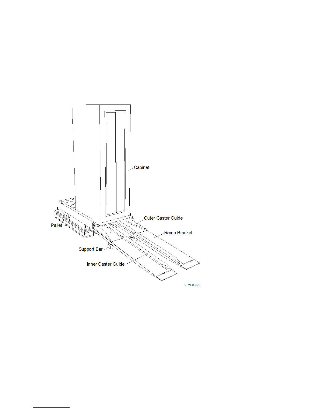
Figure 3 (page 16) shows the front view of the opened shipping container with ramps in place:
Figure 3 Front View of the Cabinet Shipping Container
When the equipment arrives, you must make sure that there is enough room to unload and unpack
the server. The specific amount of space you will need to unpack the server is based on the
dimensions of the container, the ramp and the room required to access the server so that it can be
moved to its placement destination. You will need to reserve enough space to accommodate the
crate, the ramp and the storage system as depicted in the following illustration:
16 General Site Planning
Page 17
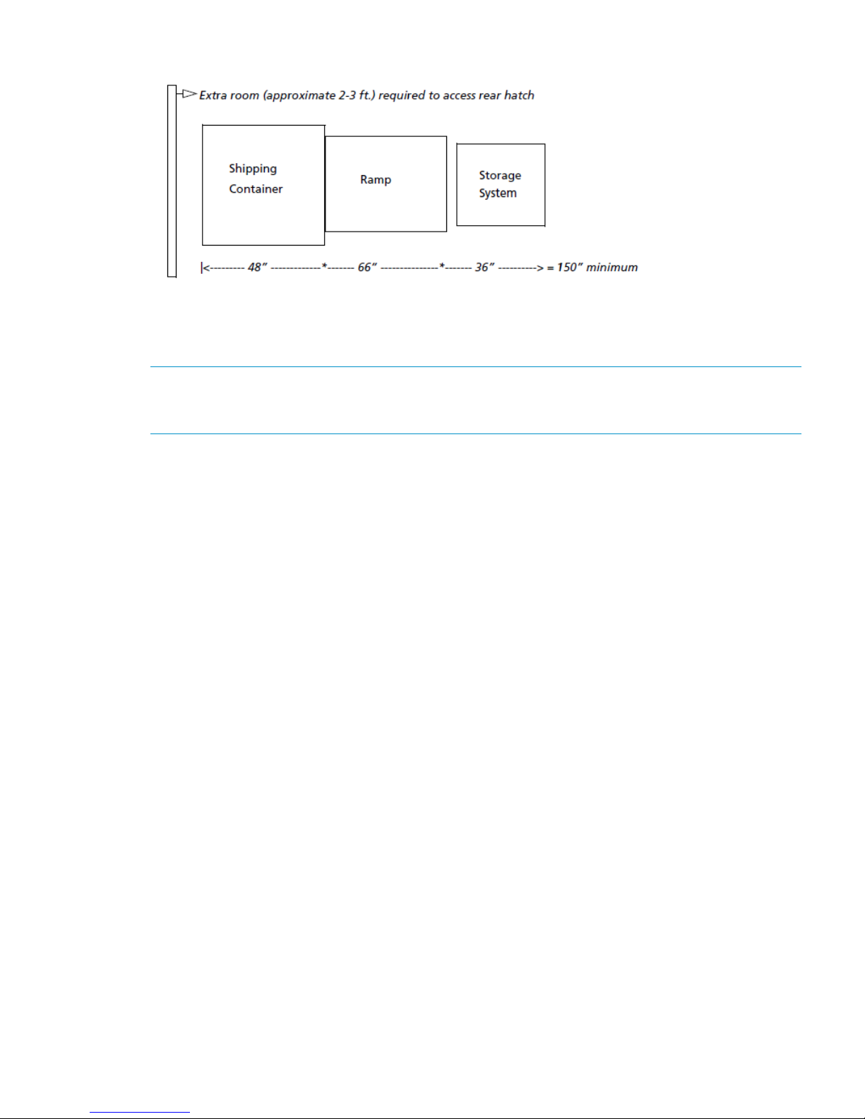
Figure 4 Total Area Required for Unpacking an HP P10000 3PAR Storage System
The specific amount of space you will need to unpack the server is based on the dimensions of the
container, the ramp and the room required to access the server so that it can be moved to its
placement destination.
NOTE: See “Structural/Environmental Considerations” (page 18)“Providing for Service Access”
(page 25) for more information on placing the storage systems and reserving room for service
access.
Acclimatization
HP 3PAR Storage Systems shipped or stored at extreme temperatures may require time to adjust
to operating temperatures before start-up. The maximum acceptable rate of temperature change
for a non-operating system is 18° F/hr (10° C/hr). The storage server requires time to acclimatize
to new environmental conditions before being powered on. During that time, it is possible to
proceed with the physical installation of the storage server; however, the storage server may need
at least 24 hours to acclimatize to a new environment prior to completing the full system installation.
If condensation is present even after the 24 hour acclimatization period, it is necessary to wait
until all condensation has evaporated before completing the power-on sequence.
Acclimatization 17
Page 18

4 Structural/Environmental Considerations
General Information
Consider the following when choosing or designing your facilities for HP 3PAR Storage Systems:
• Equipment location and layout that allows efficient use, easy maintenance, and future
expansion.
• Facility construction that provides a suitable operating environment, sufficient power and
adequate protection from fire, contamination, or other hazards.
• Suitable temperatures and appropriate air quality that is free from environmental contaminants.
The customer is responsible for maintaining the room environment according to the recommended
specifications. Environmental conditions for the room and under the floor must be maintained within
the acceptable limits to prevent any adverse impact on performance and reliability. The installation
environment should be monitored on a regular basis to ensure continued conformance to
recommended environmental specifications. The customer may request assistance from an HP 3PAR
representative to help in analyzing the site location and environment to make appropriate
recommendations.
Establishing the Proper Foundation
As with any electronic equipment that generates heat, the HP 3PAR Storage Systems must be
housed in a cool environment. Common techniques for maintaining an optimal operating
environment generally incorporate the use of raised flooring and alternating hot and cold aisle
layouts.
Benefits of Raised Floors
While not required, storage systems can be installed on raised floors with under the floor air
cooling. Raised floors will allow cables to be located safely beneath the floor. If the facility does
not have raised floors and under the floor air cooling, temperature and airflow must be in
compliance with the recommended specifications.
The raised floor system should consist of removable panels or panels on a stringer grid system,
supported by adjustable steel pedestal assemblies. The raised floor can be constructed of steel,
aluminum, or fire-retardant wood. The purpose of the raised floor system is to:
• Permit space between floors to supply cooled air to the equipment.
• Support the total weight of the system and service area loading.
• Protect interconnecting cables and power receptacles.
• Allow for future layout changes with minimum cost.
• Provide safety for personnel.
Raised Floor Requirements
There are additional structural considerations when installing storage systems in environments with
raised flooring.
NOTE: This section considers a standard raised floor construction that consists of the following:
24 in. (61-cm) square or 24 in. (61-cm) X 36-in. (91.5-cm) panels, steel or aluminum stringers,
and pedestal supports attached to an underlying concrete slab or steel deck.
Prior to installation, verify that the raised floor at the operating site meets the specifications described
in Table 10 (page 19).
18 Structural/Environmental Considerations
Page 19
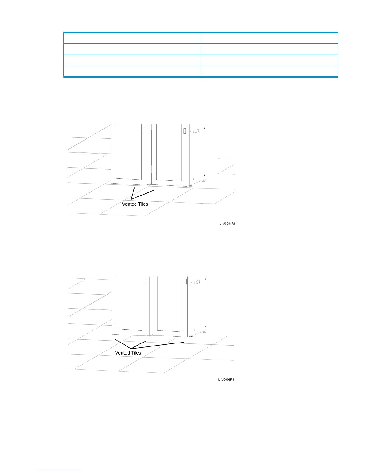
Table 10 Raised Floor Specifications
ValueSpecification
Less than 0.06 in. (1.5 mm)Less than 0 .10 in. (2.5 mm)Flatness tolerance Per 10-ft (3 m) spanOverall
Less than 0.15 in. (3.8 mm)Less than 0.02 in. (0.5 mm)Deflection DynamicPermanent
At least 5,000 lb (2,268 kg)At least 30 ft-lb (40.7 N-m)Pedestal assembly load AxialSide
Placing each storage system cabinet across two floor tiles is strongly recommended. It is also
strongly recommended that a vented floor tile be placed in front of each cabinet. Figure 5 (page 19)
shows two storage systems side-by-side, each resting across two floor tiles.
Figure 5 Adjacent Cabinets Placed Across Two Floor Panels Each (Recommended)
When necessary, a storage system can also rest across four floor tiles, with two adjacent storage
systems resting partially on the same tiles so that they use a total of six tiles, as shown in Figure 6
(page 19). Again, it is strongly recommended to have vented tiles in the front.
Figure 6 Storage System Resting Partially on the Same Floor Panels
However, before placing a cabinet on floor tiles shared with other cabinets or equipment, first
verify that the floor panels can tolerate the weight and pressure loads. Maximum weight and
pressure loads for storage servers are provided in Table 11 (page 20).
When placing cabinets with their weight shared by the same panels as shown in Figure 6 (page 19),
verify that each panel can tolerate the maximum weight per panel, calculated as follows:
Establishing the Proper Foundation 19
Page 20

where cabinet x and cabinet y are cabinets or equipment resting partially on the same floor panel.
Weight and Pressure Loads
Depending on the configuration, a storage system can weigh up to 2,000 lb (907 kg). Table 11
(page 20) provides maximum weights and pressure loads per leveling foot for storage system
cabinets. Use these values to approximate the structural support required by a storage system
cabinet.
Table 11 Maximum Weights and Pressure Loads
Maximum LoadPer Leveling
Foot
Maximum Weight Per
Leveling Foot
Maximum WeightCabinet Size
161 lb/sq in.(73 kg/sq cm)500 lb(226.8 kg)2,000 lb(907.2 kg)2M (40U)
NOTE: Table 4.2 uses nominal numbers to simplify calculations.
Tile Cutout Specifications
Figure 7 (page 21) shows the recommended tile cutout specifications for storage system cabinets.
20 Structural/Environmental Considerations
Page 21

Figure 7 Tile Cutout Specifications
WARNING! To prevent potential collapse, loaded floor panels that have cutouts to facilitate
cable routing may require additional reinforcement.
Anchoring Dimensions for Storage Systems
Some installations may prefer to anchor storage systems to the floor for better stability, especially
in seismically active locations. While HP does not supply, or specifically recommend any particular
anchoring solution, there are several third-party anchoring kits that can be procured for this purpose.
Figure 8 (page 22), Figure 9 (page 22) and Figure 10 (page 23) provide the required dimensions
for the base of the storage system cabinet:
Establishing the Proper Foundation 21
Page 22

Figure 8 Front View Dimensions for the HP P10000 3PAR Storage System
Figure 9 Side View Dimensions for the HP P10000 3PAR Storage System
22 Structural/Environmental Considerations
Page 23

Figure 10 Bottom View Dimensions for the HP P10000 3PAR Storage System
Additional Flooring Recommendations
Consider the following recommendations for raised floor installations:
• The flooring should be high enough to allow under the floor routing of cables and specified
airflow to system air intakes. The recommended minimum floor clearance is 30.5 cm (12 in).
An additional 7.6 cm (3 in) should be allowed for cables and connectors. A floor clearance
of 46 cm (18 in) is recommended for new construction.
Additional panel support may be required to restore the structural integrity of a raised floor
panel that has been cut for air opening, cable entry, and so on. Raised floors without stringers
may also require lateral support to prevent floor tile movement.
The finished floor-to-ceiling height should be a minimum of 2.44 meters (8 feet).
• The subfloor must have adequate drainage to prevent flooding and trapping of water beneath
the raised floor. Cement should be sealed to prevent the formation of particulates.
Establishing the Proper Foundation 23
Page 24

• To avoid an electrical hazard when using a metallic floor, no metal or conductive material
should be exposed to the walking surface.
• Sharp edges must be eliminated on all floor cutouts where cables pass. For wood or similar
core material, all cut edges must be covered with metal or plastic clips or grommets so that
none of the core is exposed (see NFPA 75 requirements).
• Asphalt tiles are not recommended because they produce dust that may cause equipment
malfunction.
• Carpeting is not recommended because it produces and holds dust, and can contribute to the
buildup of electrostatic charges on people and equipment.
• Most raised floors are composed of 60 cm (International/Metric) or 24 in. (Domestic/American
Standard) square floor tiles. The maximum panel size should not exceed 60 by 90 cm
(International/Metric) or 24 by 36 in. (Domestic/American Standard). The panels should have
a flame spread rating of 15 or better when tested according to the American Society for
Testing and Materials (ASTM) Standard E 84.
• The floor covering can contribute to a buildup of high static electrical charge. To minimize
static charge:
◦ Provide a conductive path to ground from the metallic raised floor structure through the
metallic supporting structure or separately from each tile.
◦ Ensure the maximum resistance for floor surface material is 20 gigohms, measured between
the floor surface and building ground.
◦ The resistance between adjacent tiles should not be less than 150 kilohms when measured
between any points on the floor, spaced 91.5 cm (36 in) apart.
◦ Maintenance of antistatic floor covering should be performed according to supplier's
recommendations.
Hot-Aisle/Cold-Aisle Cooling Layout
Air flows through the storage systems from the front to the rear, so when installing multiple storage
systems in the same room, consider facing each pair of system in a front to rear configuration. This
allows cool air to be circulated through the rows in the front of the systems and exhausted through
rows in back. This is referred to as a hot-aisle/cold-aisle layout and eliminates the direct transfer
of hot exhaust air from one system into the intake air of another as shown in Figure 11 (page 24).
Figure 11 Hot-Aisle/Cold-Aisle Layout
24 Structural/Environmental Considerations
Page 25

Form rows of racks or cabinets perpendicular to air conditioners. This formation facilitates an
unobstructed flow of heated air down the aisles to the air conditioner return ducts. Heated air must
not be forced to travel over or between the cabinets to get to the air conditioner return ducts. Doing
so could heat the air in the cold aisles. Ensure that any free-standing equipment does not allow air
to flow between the hot and cold aisles.
A cold aisle has perforated floor tiles or grates that enable cold air to rise from the raised floor
whereas the hot aisle has no tiles or grates so that hot air and cold air do not mix. Seal cable
cutouts in both hot aisles and cold aisles to increase under the floor pressure and to eliminate cold
or hot air redirection. To further optimize the airflow in hot and cold aisles, install blanking panels
at the front of all unused cabinet spaces so that hot air does not recirculate to the system’s cold air
inlet.
Providing for Service Access
HP P10000 3PAR Storage Systems are housed in 2M (40U) cabinets that measure 76.75 in. (195
cm) x 32.65 in. (82.9 cm) x 35.62 in. (90.5 cm). Cabinets feature locking rear doors and
removable side panels to improve access while installing, cabling, and servicing components.
When establishing an operating site for an storage system, provide for adequate access to cabinets
by following the access area recommendations in Table 12 (page 25).
NOTE: The V400 and V800 Storage Systems have circuit breakers located at both the front and
rear of the system. It is necessary to maintain access to both the front and rear circuit breakers.
Table 12 Recommended Access Areas for HP 3PAR Cabinets
Access Area During OperationCabinet Surface
36 in (91.4 cm)Front
30 in (76.2 cm)Rear
NoneLeft and right sides
NOTE: HP 3PAR cabinets do not require side access during operation. However, during
installation, one side of the cabinet must be removed to access the PDU power cords.
Meeting Environmental Conditions
It is recommended that you maintain a controlled environment requiring a high degree of cleanliness,
close control of temperature and humidity, and infrequent personnel access.
CAUTION: The storage system operating environment must be free from continuous vibration
and from dust and other environmental contaminants.
In addition, the operating site must comply with the following environmental specifications (Table 6
(page 12)):
Table 13 Environmental Specifications for HP 3PAR Storage Systems
ValueSpecification
Altitude
0 –10,000 ft (3,048 m)Operating
0 –40,000 ft (12,192 m)Nonoperating
Ambient temperature
50 –104° F (10–40° C)Operating
0–3,000 ft (914.4 m)
Providing for Service Access 25
Page 26

Table 13 Environmental Specifications for HP 3PAR Storage Systems (continued)
ValueSpecification
50 –95° F (10 –35° C)
3,000–10,000 ft (914–3,048 m)
–40 –203° F (–40– 95° C)Nonoperating
0–40,000 ft (0–12,192 m)
Temperature gradient
18° F/hr (10° C/hr)Operating
18° F/hr (10° C/hr)Nonoperating
20 – 80 percent noncondensing, maximum gradientRelative humidity
10 percent per hour
Maintaining the Optimal Temperature
The level of cooling required for the HP 3PAR Storage Systems is quite different from the
air-conditioning used in offices. Comfort air-conditioning systems are designed for the lower heat
and higher moisture generated by the human body. In contrast, equipment has high heat output
that is moisture-free (sensible heat). In comfort systems, sensible heat normally produces 60 to 70
percent of the load, whereas the dry heat of electronic equipment produces a sensible heat ratio
of over 95 percent.
Prior to installation, verify that the operating site is equipped with a cooling system that can support
all thermal emissions. Use the average and maximum thermal emissions of storage server components
listed in Table 14 (page 26) to estimate the cooling requirements for a storage system based on
a specific system configuration.
Proper site layout is critical to ensure the ambient temperature near the intake of the system does
not rise beyond the system specifications. Exceeding the maximum ambient temperature for any
period negatively affects the system’s reliability and performance, and continued operation for
extended periods under such conditions might actually cause the system to shut down.
CAUTION: Heated air from nearby equipment should not exhaust into the front of the storage
system.
Table 14 Thermal Emissions of Storage System Components
Maximum Thermal EmissionsAverage Thermal EmissionsComponent (Fully Populated)
3,004 BTU/hr (757 Kcal/hr)2,164 BTU/hr (545.3 Kcal/hr)Controller node (pair)
1
4,973 BTU/hr (1,253.2 Kcal/hr)3,657 BTU/hr (921.6 Kcal/hr)Drive chassis (single)
9,946 BTU/hr (2,506.4 Kcal/hr)7,314 BTU/hr (1,843.2 Kcal/hr)Drive chassis (pair)
2
1 Controller nodes can only be installed in pairs.
2 HP P10000 3PAR Storage Systems require a minimum of two drive chassis; however, additional drive chassis can be
installed individually.
Storage systems can tolerate temperature and humidity fluctuations if the specified guidelines are
understood and followed. Exposure to conditions outside the specified ranges may damage the
system or its components.
Before a system is powered on, the air entering the subsystem must be clean and within the ranges
specified for temperatures and humidity. The room humidity must be kept sufficiently low to prevent
condensation on or within the subsystem, and must never exceed the limit specified in the subsystem
26 Structural/Environmental Considerations
Page 27

environmental requirements tables, including transients. The system must never be exposed to
conditions that could cause internal condensation to occur within the subsystem.
The air-conditioning units should have controls monitoring under the floor output that respond to
1° C (2° F) and 5 percent relative humidity. Humidification is normally required to replace moisture
removed during the cooling process. The relative humidity for a subsystem equipment room should
be set at 40 percent. This level is sufficient to suppress electromagnetic charge buildup, and low
enough to avoid the risk of corrosion and condensation. To avoid air contamination from the
humidifier, water treatment may be necessary in areas with high mineral content.
Air Supply and Flow
The air flow capacity of the facility where the storage systems are installed needs to be sufficient
to remove the heat generated by the equipment. In addition, the air handlers must provide the
airflow volume required by the units being cooled. To ensure this airflow, the facility must have a
positive under the floor air pressure (if the facility has raised floors). When conditions within the
computer room are changed (new units are added, the computer system is moved) airflow checks
should be made.
The amount of outside (make-up) air should be kept to the minimum needed to create a slight
positive pressure within the room, and should not exceed industry recommendations of 0.3 cubic
meter/minute (10 cubic feet/minute) per person stationed in the equipment room. While
recommendations for outside air in comfort air-conditioning are 10 to 15 percent of the airflow,
the computer room environment is cleaner and operates more efficiently if outside air is kept below
1 percent of the airflow. Cooling/heating and humidification needs are reduced, and a minimum
of contaminated building air is introduced into the installation area.
Air Cleanliness
Air contaminants can cause equipment malfunction and can damage storage systems. It is essential
that steps be taken to prevent air contaminants, such as metal particles, solvent vapors, corrosive
gases, soot, airborne fibers, or salt, from entering or being generated within the server room
environment.
A high-efficiency air filter should be employed on each air inlet for outside air to stop dust at the
point of entry to the installation site. Special additional filtering is necessary where the environment
is exposed to salt air, corrosive gases, or unusual dust/dirt conditions. Electronic equipment is
sensitive to air contaminants such as:
• Excessive amounts of soot particles
• Condensate particulates such as carbonates
• Concrete particulates from unsealed concrete
• Metal flakes or filings, such as those produced by sawing, filing, or drilling
• Floor-cleaning solutions with high ammonia content.
• Deteriorating/decomposing building materials, including floor tiles, fabrics, sheetrock,
insulation, and acoustical tiles
• Pollutants generated by any servicing performed in and around the computer room
• Paper chaff, dust, and toners from printers within the computer room
• Processing chemicals from reproduction equipment such as microfiche processors.
In electronic equipment, contaminants cause connector contact and motor-bearing degradation.
They also cause electrical leakage, shorting paths between integrated circuit leads and between
printed wiring traces on printed circuit boards.
Air supplied to and circulated within the server room and under the floor plenums should ideally
pass through mechanical or electrostatic filters. HVAC ducts and plenums and subfloor areas,
including cable raceway openings where used, should be kept clean. All unused cables, hardware,
Meeting Environmental Conditions 27
Page 28

and debris should be removed from the under the floor area to avoid becoming dust/dirt traps or
potential sources of rust.
During major changes in the server room environment, special considerations must be taken into
account whenever any drilling, sawing, welding, brazing, etc., is performed.
Precautions must be taken to prevent material particles (concrete or metal particles, etc.) from
becoming airborne. Storage systems should be powered down during construction that requires
any drilling, sawing, welding, brazing, etc. In addition, all debris must be removed before powering
up the system(s). Maximum concentrations of corrosive gases and solvent vapors must also be
considered.
28 Structural/Environmental Considerations
Page 29

5 Power Requirements
This chapter describes the general power requirements for HP P10000 3PAR Storage Systems.
Powering HP P10000 3PAR Storage Systems
The cabinets used to house the HP P10000 3PAR Storage System components include 4 Power
Distribution Units (PDUs). Each node has 2 dedicated power supplies and each drive chasis has
4 power supplies. Drive cages and controller nodes depend on these power supplies; the drive
chassis power supply is located at the rear of the drive chassis while the node power supply is
located behind the cable management tray in the node chassis. The PDUs are mounted vertically
on the left side at the rear of the cabinet.
Powering HP P10000 3PAR Storage Systems 29
Page 30

Figure 12 Power Supplies Within the Power Domains
30 Power Requirements
Page 31

HP 3PAR cabinets contain four (PDUs) and each requires service from a dedicated single-phase
200-240 VAC (200-250 VAC International), 30-A (32-A International) grounded electrical circuit.
However, for optimal reliability and data accessibility, HP recommends a redundant AC
configuration that uses independent sources to provide a dedicated, grounded electrical circuit to
each PDU as shown in the following configuration:
NOTE: If a storage system cabinet does not have components installed in the top portion of the
cabinet, do not connect and use the two upper PDUs (PDU 2 and PDU 3) to power the system.
Redundant power is still supplied to the lower bays in the cabinet through PDU 0 and PDU 1.
Storage system PDUs are equipped with NEMA® L6–30 or IEC 60309 connectors, depending on
the region. International PDUs are equipped with IEC 60309, 2P+E (3 wire, 2 Pole + Earth Ground)
connectors. The appropriate receptacles or adapters are necessary at the operating site to
accommodate these connectors.
Power Distribution Units (PDUs)
For each cabinet, four Power Distribution Units (PDUs) are mounted vertically on the left side of the
rear of the cabinet. Numbers for PDUs are assigned beginning with 0, from bottom to top.
Figure 13 (page 32) illustrates the four PDUs in the HP P10000 3PAR Storage System cabinet.
Powering HP P10000 3PAR Storage Systems 31
Page 32

Figure 13 Power Distribution Units
Each PDU is equipped with two power banks and separate circuit breakers, used exclusively for
storage system components.
32 Power Requirements
Page 33

Figure 14 Power Banks in the PDU
WARNING! To avoid possible injury, damage to storage system equipment, and potential loss
of data, do not use the surplus power outlets in the storage server PDUs. Never use outlets in the
PDUs to power components that do not belong to the storage server or to power storage server
components that reside in other cabinets.
Battery Modules
HP P10000 3PAR Storage Systems include one or two battery compartments that hold up to four
battery modules each. The battery compartment is part of the node chassis and adjacent to the
node fan compartment (Figure 15 (page 33)).
Figure 15 Battery Modules (BM) Front View of Cabinet
Power Cord Connections
HP 3PAR Storage Systems arrive with all internal power cords configured. Each PDU AC cord
connects to the wall outlet and supplies power to the node and drive chassis power supplies. The
power can be routed from the top or bottom of the cabinet (Figure 16 (page 34)).
Powering HP P10000 3PAR Storage Systems 33
Page 34

Figure 16 Routing of the Main Power Cords
Electrical Requirements and Limitations
Before physically installing a storage system, verify that the operating site has the necessary electrical
circuitry. Each storage system requires 4 (200 - 240) Volt, 30 Amp outlets or 2 outlets if only the
bottom half of the cabinet is occupied. For proper redundant power protection, power should be
supplied from two or more power sources.
Use the approximate current requirements for storage server components listed in Table 15 (page 34)
to estimate the current requirements for a specific system configuration.
Power and Heat Specifications
The following table lists the electrical power requirements for the HP P10000 3PAR Storage Systems.
Table 15 HP P10000 3PAR Storage System Power Requirements
2 Meter Cabinet
9,984Max. Watts per Cabinet (fully
populated)
34,075Max. BTUs/hour per cabinet
(fully populated)
200 - 240Input Voltage (VAC)
50 - 60Frequency (Hz)
30A per PDU (de-rated to 24A)Circuit Breaker Max
200Drive Chassis (no magazines)
(4) L6-30P Plug (North America
and Japan) (4) IEC-60309 Plug
(EU and Korea)
Power Connectors
IdleTransactionalNode Pair (fully populated)
34 Power Requirements
Page 35

Table 15 HP P10000 3PAR Storage System Power Requirements (continued)
630705Watts
2,1502,406BTUs/hour (fully populated)
200200Drive Chassis (no magazines)
Drive Magazine
3
4 x 100 GB SSD Drive Magazine
5.59.8Watts
1933BTUs/hour
4 x 200 GB SSD Drive Magazine
710.3Watts
2435BTUs/hour
4 x 300 GB FC Drive Magazine
5775Watts
195256BTUs/hour
4 x 600 GB FC Drive Magazine
6576Watts
222258BTUs/hour
4 x 2 TB NL Drive Magazine
3862Watts
131211BTUs/hour
Service Processor
317Supermicro II Watts
1,082 BTUs/hr.Supermicro II BTUs/hour (fully populated)
NOTE: All calculations in Table 15 (page 34) are based on fully populated components; for
example, a fully populated drive chassis contains 40 disks. Specifications are not provided for
partially populated drive chassis because different drives and magazine types have varying current
requirements and can be installed in a variety of different combinations. Therefore, only the
maximum, fully loaded configuration is cited.
NOTE: The total system peak inrush current on system startup can vary depending on the system
configuration but is mitigated through a staggered (sequenced) drive spin-up and by distributing
the load equally unless there is a failure on a given line.
Power Quality
The quality of the input power is critical to the performance and reliability of HP 3PAR Storage
Systems. Variations in the input power can cause a power failure or malfunction. Many of the
causes of transient signals and noise on commercial power lines are difficult to locate or are beyond
the customer’s control. To reduce the impact of the irregularities, some form of power conditioning
may be needed. Consult your electrician for assistance.
Power Quality 35
Page 36

Voltage and Frequency Tolerance
Steady state voltage must be maintained within 10 percent of the normal rated voltage, measured
(under load) at the power input terminal of the specified server. The frequency must be maintained
at (50-60 HZ), 1 phase 50/60 +2 percent, -4 percent.
When there is a possibility of brownouts or other marginal voltage conditions, installing a voltage
monitor may be advisable.
Voltage Spikes
The HP 3PAR Storage Systems are tested to comply with the EN 61000-45 standard.
Installing a lightning protection device on the server room power source is recommended when
the following conditions exist:
• The primary power is supplied by an overhead power service.
• The utility company installs lightning protectors on the primary power source.
• The area is subject to electrical storms or an equivalent type of power surge.
Electrostatic Discharge
Storage systems are susceptible to failure due to Electrostatic Discharge (ESD). Electrostatic charges
can accumulate on people and furniture because of direct contact with floor coverings or movement
while in contact with furniture coverings. Discharge of static electricity to a metal surface on server
cabinets can interfere with the system’s operation and cause discomfort to anyone who comes in
contact with it.
Some factors that contribute to electrostatic discharge are:
• High-resistance floor covering
• Carpeting without anti-static properties
• Low humidity (less than 20 percent)
The HP P10000 3PAR Storage System is tested to comply with the EN 61000-45 standard.
Branch Circuits
The individual panel branch circuits should be protected by suitable circuit breakers properly rated
according to manufacturer specifications and applicable codes. Each circuit breaker should be
labeled to identify the branch circuit it is controlling. The receptacle should also be labeled. Plan
on a circuit breaker maximum of 30 A per PDU (de-rated to 24 A).
Emergency Power Control
As a safety precaution, you might consider providing emergency power-off controls for disconnecting
the main service wiring that supplies storage systems. Install these controls at a convenient place
for the operators and next to the main exit doors of the room after checking local electrical codes
for further guidelines.
Redundant Power
The HP P10000 3PAR Storage System cabinets support redundant power within the system through
the use of redundant PDUs and redundant power supplies.
The 2M cabinet is equipped with four power distribution units (PDU) in the rear and the PDUs are
vertically mounted along the left panel for a V400, V800, and expansion cabinet configuration.
As shown in Figure 17 (page 37), power domains within the storage system are distributed between
the upper and lower halves of the cabinet.
36 Power Requirements
Page 37

Figure 17 Rear View of the Power Domains Within the Controller Nodes and Drive Chassis for
V800
WARNING! To avoid possible injury, damage to storage system equipment, and potential loss
of data, do not use the surplus power outlets in the storage system PDUs. Never use outlets in the
PDUs to power components that do not belong to the storage system or to power storage system
components that reside in other cabinets.
To support redundant power:
• The power supplies in each power domain must connect to separate PDUs.
• Each PDU in the system must connect to an independent AC circuit.
Redundant Power 37
Page 38

Figure 18 Redundant Power Configuration for the HP 3PAR V400 Storage System
38 Power Requirements
Page 39

Figure 19 Redundant Power Configuration for the HP 3PAR V800 Storage System
Redundant Power 39
Page 40

Figure 20 Redundant Power Configuration Diagram (HP P10000 3PAR Storage System Expandsion
Node Cabinet
40 Power Requirements
Page 41

6 Network, Cabling and Connectivity
This chapter provides information on determining the best network configuration for the HP 3PAR
Storage Systems being installed at your site including the necessary connections and cable routing
options.
NOTE: The information that follows assumes an established network and discusses how to connect
a storage system to that network.
Planning Network Access
External Ethernet, Fibre Channel, connections are completed at the time of installation. The customer
site will require two static IPs.
These external connections are necessary to:
• Establish direct connections from the controller nodes to the host computer or computers.
• Connect the storage system to the network, enabling storage system management through the
InForm Management Console and CLI.
• Enable access to storage system equipment from a service processor.
• Enable HP Customer Services personnel to locally and remotely monitor and service the storage
system.
NOTE: All networking equipment, including all necessary switches, hubs, and cables, are to be
provided by the customer unless otherwise indicated.
Supported Network Topologies
Several different network topologies can be used to connect the storage system to the local area
network, depending on operating site policies and requirements. Currently, the major supported
topologies are shared and private. However, other possible network configurations might be
available. To learn more, ask your sales and support representative.
NOTE: To provide redundancy and to permit online software upgrades, both controller nodes
in a single horizontal node pair (for example, nodes 0 and 1, nodes 2 and 3, and so on) must
maintain connections to the internal customer network.
Shared Network
With a shared network topology, the storage system and Service Processor (SP) share the internal
customer network.
Planning Network Access 41
Page 42

A shared topology requires:
• A static IP address and system name for the storage system.
• Two Ethernet connections from a switch or hub to the storage system controller nodes.
• A static IP address for the SP.
• One Ethernet connection from a switch or hub to the SP.
• At least one management station on the network segment.
Private Network
With a private network topology, the storage system and the Service Processor (SP) sit on the same
private network segment on the customer local area network. All management workstations used
to administer the system must also sit on the same private network segment (Figure 21 (page 42)).
Figure 21 Storage System and Service Processor on a Private Segment (Private Topology)
A private topology requires:
• A static IP address for the storage system.
• Two Ethernet connections from the storage system to a private network segment.
• One Ethernet connection from the SP to the private network segment.
• At least one management station on the private network segment.
NOTE: It is strongly recommended that the private network segment also have a management
station to communicate with the SP.
TCP/IP Port Assignments
Table 16 (page 42) describes the TCP/IP port assignments for communication between various
components:
Table 16 TCP/IP Port Usage Table
Flow of TrafficUsagePort
Used for storage server monitoring
and configuration through SSH
22: The Secure Shell (SSH) Protocol
42 Network, Cabling and Connectivity
Page 43

Table 16 TCP/IP Port Usage Table (continued)
Flow of TrafficUsagePort
connections by the following
components:
3rd Party SSH Client <--> 3PAR Service
• HP 3PAR Service Processor
Processor
• HP 3PAR InForm CLI Client
3rd Party SSH Client <--> HP 3PAR CLI
• HP 3PAR Connection Porta
Client
HP 3PAR Connection Portal <--> HP
3PAR Service Processor
Used by the following component to
communicate using the HTTP protocol:
80: World Wide Web HTTP
HP 3PAR Service Processor
HP 3PAR Service Processor --> WWW
Used for storage system monitoring
and configuration by third-party SNMP
161: SNMP
Manager applications by the following
component:
HP 3PAR SNMP Agent
3rd Party SNMP Manager <--> HP
3PAR SNMP agent
Used by the HP 3PAR SNMP agent to
send unsolicited alerts as SNMPv2c
162: SNMPTRAP
traps for 3rd party SNMP Manager
applications by the following
component:
HP 3PAR SNMP Agent
3rd Party SNMP Manager <-- HP 3PAR
SNMP agent
Used by the HP 3PAR CIM API to
provide CIM Server location
427: Service Location Protocol (SLP)
information by the following
component:
HP 3PAR CIM Server
3rd Party CIM Client <--> HP 3PAR CIM
Server
Passes unsolicited events from the
storage system and is used by the
following component:
5781: 3PAR Event Reporting Service
HP 3PAR Service Processor
Service Processor <--> HP 3PAR Event
Service
(This port was used for IMC events
prior to OS version 2.3.1.)
Used for storage system monitoring
and configuration over an unsecured
channel by the following components:
5782: 3PAR Management Service
(unsecured)
• HP 3PAR InForm Management
Console
HP 3PAR IMC <--> HP 3PAR CLI Server
• HP 3PAR InForm CLI
• HP 3PAR Recovery Manager
• HP 3PAR System Reporter
HP 3PAR CLI <--> HP 3PAR CLI Server
• HP 3PAR Service Processor
Recovery Manager <--> HP 3PAR CLI
(Port 2540 used prior to 2.2.4.)
Server
TCP/IP Port Assignments 43
Page 44

Table 16 TCP/IP Port Usage Table (continued)
Flow of TrafficUsagePort
HP 3PAR System Reporter <--> HP 3PAR
CLI Server
HP 3PAR Service Processor --> HP 3PAR
CLI Server
Used for storage server monitoring
and configuration over a secured
channel by the following components:
5783: 3PAR Management Service
with SSL (secured)
• HP 3PAR InForm Management
Console
HP 3PAR IMC <--> HP 3PAR CLI Server
• HP 3PAR InForm CLI
• HP 3PAR Recovery Manager
• HP 3PAR System Reporter
HP 3PAR CLI <--> HP 3PAR CLI Server
• HP 3PAR Service Processor
Recovery Manager <--> HP 3PAR CLI
(Port 2550 was used prior to 2.2.4)
Server
HP 3PAR System Reporter <--> HP 3PAR
CLI Server
HP 3PAR Service Processor --> HP 3PAR
CLI Server
Used by the Remote Copy Software
to receive remote replication storage
5785: 3PAR InForm Remote Copy
data sent by the Remote Copy service
from another HP 3PAR Storage Array.
HP 3PAR Remote Copy Software
(Ports 3490/3491 used for 2.2.2 and
prior -- ports 3491/3492 used for
2.2.3 and 2.2.4).
HP 3PAR Remote Copy Softtware on
the HP 3PAR Storage System<-- 3PAR
Remote Copy on HP 3PAR Storage
System
(A dynamic port is allocated for sending
data from the Remote Copy Software
on the HP 3PAR Storage System.)
Used for storage server monitoring
and configuration over an unsecured
channel by the following component:
5988: WBEM CIM-XML (HTTP)
(unsecured)
HP 3PAR CIM Server
3rd Party CIM Client <--> HP 3PAR CIM
Server
Used for storage server monitoring
and configuration over a secured
channel by the following component:
5989: WBEMCIM-XML (HTTPS)
(secured)
HP 3PAR CIM Server
44 Network, Cabling and Connectivity
Page 45

Table 16 TCP/IP Port Usage Table (continued)
Flow of TrafficUsagePort
3rd Party CIM Client <--> HP 3PAR CIM
Server
NOTE: If configured to do so, the storage system is capable of communication with a customer
defined host via UDP port 514 (syslog).
Controller Node Connections
The controller nodes provide the slots that are required to connect to external drives, systems and
other devices. As shown in Figure 22 (page 45), a controller node contains nine PCI slots.
The following slots connect PCI adapters such as quad-port Fibre Channel Adapters.
Figure 22 Controller Node PCI Slots
The number of ports available for the host connection will vary based on the configuration.
Depending on the number of controller nodes in the system, the type of Fibre Channel adapters
installed, and the method of drive chassis connection being used, a HP P10000 3PAR Storage
System can support a maximum of 2-48 drive chassis. Controller nodes can hold a maximum of
nine PCI adapters.
Fibre Channel SFPs (Adapter) adapters are used to connect to the customer FC switch and/or hosts
and connect controller nodes to drive chassis within the system. They can also be used for Remote
Copy operations.
Controller Node Connections 45
Page 46

Required Cables
The quantities and lengths of the cables required for storage system installation vary according to
the specific storage system and network configuration. Fibre Channel cables are used externally
to connect the controller node to the customer switch or host (in the case of a directly connected
host). Fibre Channel cables are used internally to connect the controller node to the drive chassis
(inter-cabinet or cabinet to cabinet).
The Fibre Channel cables provided by HP have a custom strain relief feature to help maintain the
proper bend radius of the cables. For this reason, HP requires that you use only Fibre Channel
cables provided by HP. However, HP does not provide any networking cables or equipment such
as Ethernet and modem cables. Table 7 (page 13) identifies the types of cables commonly required
for storage system installation.
Table 17 Required Cables
Connector TypeOutside DiameterCable Type
RJ-45StandardEthernet (Category 5) 3 cables
minimum with 2 static IPs
LC-LC1.6 mmMultimode Fibre Channel
RJ-45StandardModem
NOTE: For Ethernet and Fibre Channel cables that connect the storage system to the network
and hosts, reserve approximately 7 feet (2 meters) of each cable for internal routing within the
storage server cabinet. Measure the distance between the two cabinets and add 14 feet (4 meters)
to determine the total length of cable required.
External Cable Connections
Table 18 (page 46) includes specific guidelines for connecting the controller nodes to the network
and to host computers. Refer to “Supported Network Topologies” (page 41) for descriptions of the
supported network topologies.
Table 18 External Controller Node Connections
Recommended ConfigurationMinimum ConfigurationConnection Type
See Supported Network Topologies in
Chapter 6.
Connection from the Ethernet switch
or hub to two controller nodes
Ethernet
Separate connections from host
computers to each node, with
connections distributed evenly across
all nodes
1
Connection from a host computer to
one controller node
Fibre Channel
Varies according to system and network
configuration
NoneMaintenance
1 To provide redundancy and to permit online software upgrades, both controller nodes in a single horizontal node pair
(for example, nodes 0 and 1, nodes 2 and 3, and so on) must maintain connections to each host server.
• Each controller node supports one Ethernet connection to a switch or hub. Separate connections
from the Ethernet switch or hub to at least two controller nodes are required to support
redundancy.
With redundancy, one IP address is shared between the two connections and only one network
connection is active at a time. If the active network connection fails, the IP address is
automatically moved to the surviving network connection.
• At a minimum, the storage system requires one Fibre Channel (or iSCSI) connection from a
host computer to a controller node. However, separate connections from each host computer
46 Network, Cabling and Connectivity
Page 47

to each of the controller nodes in the storage server, with connections distributed evenly across
all nodes, are recommended.
(Table 9 (page 13)) shows the maximum supported Fibre Channel cable length based on the cable
size and port speed.
Table 19 Cable Limitations for Fibre Channel Host Connectivity
Cable Length LimitSpeedCable Size
100 meters2 Gbps62.5 micron
70 meters4 Gbps62.5 micron
300 meters2 Gbps50 micron
150 meters4 Gbps50 micron
Internal Cable Connections
For storage systems housed in single cabinets, internal system Fibre Channel cabling is complete
upon arrival. For multiple-cabinet configurations, the installation technician completes connections
between the controller node cabinet and the drive chassis cabinet or cabinets.
NOTE: For important exceptions to the cabling rules and guidelines described in this section,
see the HP 3PAR InForm OS Administrator’s Guide.
The following table (Table 8 (page 13)) shows the typical Fibre Channel cable lengths required
for a given type of connection:
Table 20 Fibre Channel Cable Usage Guidelines
Used for...Cable Length
drive chassis to controller node connections in the same
side of the same cabinet (for example, an even-numbered
drive cage to an even-numbered node).
2 m
drive chassis to controller node connections across the
same cabinet (for example, an even-numbered drive cage
to an odd-numbered node).
4 m
cabling between cabinets. Always round up to the nearest
size.
10 m, 50 m, 100 m
Cable Routing Options
Storage system cabinets have both upper and lower access openings available for Fibre Channel
cable routing (Figure 23 (page 48)). It is also possible to route network cables and main power
cords through specially designated upper and lower openings in the cabinet.
Internal Cable Connections 47
Page 48

Figure 23 Bringing Cables Into the Cabinets Through Access Openings
NOTE: For Gigabit Ethernet (GbE), iSCSI and Fibre Channel cables that connect the storage
system to the customer network or hosts, approximately 7 feet (2 meters) of each cable must be
reserved for internal routing within the storage system cabinet.
Service Processor Connections
The Service Processor provides remote error detection and reporting and supports diagnostic and
maintenance activities for HP 3PAR Storage Systemss. The service processor (Figure 24 (page 48))
is provided by 3PAR.
Figure 24 Supermicro Service Processor Ethernet Ports
In general, one service processor is required per storage system. Each storage system installed at
an operating site includes a service processor that is installed in the same cabinet as the storage
system controller nodes. The data collected by the service processor is used by HP to maintain,
troubleshoot, and upgrade the HP equipment on the customer site. To perform these activities, the
service processor must communicate with HP Central or a local service provider. The connection
48 Network, Cabling and Connectivity
Page 49

between the service processor and HP Central or a local service provider can be made using the
customer network and the Internet, or through a point-to-point connection using a modem.
Connections that use the customer network pass through the customer’s firewall while connections
that use a modem bypass the customer’s firewall. When a designated management workstation
sits on the same network as the service processor (as described in “Supported Network Topologies”
(page 41)) and is configured to access the service processor, the customer has the option of blocking
external communications at any time.
Table 21 (page 49) summarizes the connectivity options for both data transfer and remote
operations. Data transfer involves external communications between the service processor and HP
or another connection portal. Remote operations include problem solving and diagnostics performed
from a remote location. HP recommends that both data transfer and remote operations take place
through the customer network when possible.
Table 21 Service Processor Connectivity Options
NotesSoftware Update MethodConnection Type Data Transfer /
Remote Ops
This is the preferred method of service
processor connectivity
Remote update capabilityNetwork / Network
Lower bandwidth inbound inhibits large
file transfers.
Locally by CDNetwork / Modem
Remote operations are not allowed.Locally by CDNetwork / Blocked
Connecting the Service Processor
The service processor uses customer-supplied connections, as outlined in “Supported Network
Topologies” (page 41). Table 22 (page 49) provides general guidelines for completing these
external connections.
Table 22 Service Processor Connections
ConfigurationConnection type
For service processor: connection from the RJ-45 connector
in the eth 0 port at the rear of the service processor to an
Ethernet hub or switch).
Ethernet
Service Processor Connections 49
Page 50

A Regulatory compliance notices
Regulatory compliance identification numbers
For the purpose of regulatory compliance certifications and identification, this product has been
assigned a unique regulatory model number. The regulatory model number can be found on the
product nameplate label, along with all required approval markings and information. When
requesting compliance information for this product, always refer to this regulatory model number.
The regulatory model number is not the marketing name or model number of the product.
Product specific information:
HP ________________
Regulatory model number: _____________
FCC and CISPR classification: _____________
Federal Communications Commission notice
Part 15 of the Federal Communications Commission (FCC) Rules and Regulations has established
Radio Frequency (RF) emission limits to provide an interference-free radio frequency spectrum.
Many electronic devices, including computers, generate RF energy incidental to their intended
function and are, therefore, covered by these rules. These rules place computers and related
peripheral devices into two classes, A and B, depending upon their intended installation. Class A
devices are those that may reasonably be expected to be installed in a business or commercial
environment. Class B devices are those that may reasonably be expected to be installed in a
residential environment (for example, personal computers). The FCC requires devices in both classes
to bear a label indicating the interference potential of the device as well as additional operating
instructions for the user.
FCC rating label
The FCC rating label on the device shows the classification (A or B) of the equipment. Class B
devices have an FCC logo or ID on the label. Class A devices do not have an FCC logo or ID on
the label. After you determine the class of the device, refer to the corresponding statement.
Class A equipment
This equipment has been tested and found to comply with the limits for a Class A digital device,
pursuant to Part 15 of the FCC rules. These limits are designed to provide reasonable protection
against harmful interference when the equipment is operated in a commercial environment. This
equipment generates, uses, and can radiate radio frequency energy and, if not installed and used
in accordance with the instructions, may cause harmful interference to radio communications.
Operation of this equipment in a residential area is likely to cause harmful interference, in which
case the user will be required to correct the interference at personal expense.
Class B equipment
This equipment has been tested and found to comply with the limits for a Class B digital device,
pursuant to Part 15 of the FCC Rules. These limits are designed to provide reasonable protection
against harmful interference in a residential installation. This equipment generates, uses, and can
radiate radio frequency energy and, if not installed and used in accordance with the instructions,
may cause harmful interference to radio communications. However, there is no guarantee that
interference will not occur in a particular installation. If this equipment does cause harmful
interference to radio or television reception, which can be determined by turning the equipment
off and on, the user is encouraged to try to correct the interference by one or more of the following
measures:
• Reorient or relocate the receiving antenna.
• Increase the separation between the equipment and receiver.
50 Regulatory compliance notices
Page 51

• Connect the equipment into an outlet on a circuit that is different from that to which the receiver
is connected.
• Consult the dealer or an experienced radio or television technician for help.
Declaration of Conformity for products marked with the FCC logo, United States only
This device complies with Part 15 of the FCC Rules. Operation is subject to the following two
conditions: (1) this device may not cause harmful interference, and (2) this device must accept any
interference received, including interference that may cause undesired operation.
For questions regarding this FCC declaration, contact us by mail or telephone:
• Hewlett-Packard Company P.O. Box 692000, Mail Stop 510101 Houston, Texas 77269-2000
• Or call 1-281-514-3333
Modification
The FCC requires the user to be notified that any changes or modifications made to this device
that are not expressly approved by Hewlett-Packard Company may void the user's authority to
operate the equipment.
Cables
When provided, connections to this device must be made with shielded cables with metallic RFI/EMI
connector hoods in order to maintain compliance with FCC Rules and Regulations.
Canadian notice (Avis Canadien)
Class A equipment
This Class A digital apparatus meets all requirements of the Canadian Interference-Causing
Equipment Regulations.
Cet appareil numérique de la class A respecte toutes les exigences du Règlement sur le matériel
brouilleur du Canada.
Class B equipment
This Class B digital apparatus meets all requirements of the Canadian Interference-Causing
Equipment Regulations.
Cet appareil numérique de la class B respecte toutes les exigences du Règlement sur le matériel
brouilleur du Canada.
European Union notice
This product complies with the following EU directives:
• Low Voltage Directive 2006/95/EC
• EMC Directive 2004/108/EC
Compliance with these directives implies conformity to applicable harmonized European standards
(European Norms) which are listed on the EU Declaration of Conformity issued by Hewlett-Packard
for this product or product family.
This compliance is indicated by the following conformity marking placed on the product:
This marking is valid for non-Telecom products and EU
harmonized Telecom products (e.g., Bluetooth).
Certificates can be obtained from http://www.hp.com/go/certificates.
Canadian notice (Avis Canadien) 51
Page 52

Hewlett-Packard GmbH, HQ-TRE, Herrenberger Strasse 140, 71034 Boeblingen, Germany
Japanese notices
Japanese VCCI-A notice
Japanese VCCI-B notice
Japanese VCCI marking
Japanese power cord statement
Korean notices
Class A equipment
Class B equipment
52 Regulatory compliance notices
Page 53

Taiwanese notices
BSMI Class A notice
Taiwan battery recycle statement
Turkish recycling notice
Türkiye Cumhuriyeti: EEE Yönetmeliğine Uygundur
Vietnamese Information Technology and Communications compliance
marking
Recycling notices
English recycling notice
Disposal of waste equipment by users in private household in the European Union
This symbol means do not dispose of your product with your other household waste. Instead, you should
protect human health and the environment by handing over your waste equipment to a designated
collection point for the recycling of waste electrical and electronic equipment. For more information,
please contact your household waste disposal service
Taiwanese notices 53
Page 54

Bulgarian recycling notice
Изхвърляне на отпадъчно оборудване от потребители в частни домакинства в Европейския
съюз
Този символ върху продукта или опаковката му показва, че продуктът не трябва да се изхвърля заедно
с другите битови отпадъци. Вместо това, трябва да предпазите човешкото здраве и околната среда,
като предадете отпадъчното оборудване в предназначен за събирането му пункт за рециклиране на
неизползваемо електрическо и електронно борудване. За допълнителна информация се свържете с
фирмата по чистота, чиито услуги използвате.
Czech recycling notice
Likvidace zařízení v domácnostech v Evropské unii
Tento symbol znamená, že nesmíte tento produkt likvidovat spolu s jiným domovním odpadem. Místo
toho byste měli chránit lidské zdraví a životní prostředí tím, že jej předáte na k tomu určené sběrné
pracoviště, kde se zabývají recyklací elektrického a elektronického vybavení. Pro více informací kontaktujte
společnost zabývající se sběrem a svozem domovního odpadu.
Danish recycling notice
Bortskaffelse af brugt udstyr hos brugere i private hjem i EU
Dette symbol betyder, at produktet ikke må bortskaffes sammen med andet husholdningsaffald. Du skal
i stedet den menneskelige sundhed og miljøet ved at afl evere dit brugte udstyr på et dertil beregnet
indsamlingssted for af brugt, elektrisk og elektronisk udstyr. Kontakt nærmeste renovationsafdeling for
yderligere oplysninger.
Dutch recycling notice
Inzameling van afgedankte apparatuur van particuliere huishoudens in de Europese Unie
Dit symbool betekent dat het product niet mag worden gedeponeerd bij het overige huishoudelijke afval.
Bescherm de gezondheid en het milieu door afgedankte apparatuur in te leveren bij een hiervoor bestemd
inzamelpunt voor recycling van afgedankte elektrische en elektronische apparatuur. Neem voor meer
informatie contact op met uw gemeentereinigingsdienst.
Estonian recycling notice
Äravisatavate seadmete likvideerimine Euroopa Liidu eramajapidamistes
See märk näitab, et seadet ei tohi visata olmeprügi hulka. Inimeste tervise ja keskkonna säästmise nimel
tuleb äravisatav toode tuua elektriliste ja elektrooniliste seadmete käitlemisega egelevasse kogumispunkti.
Küsimuste korral pöörduge kohaliku prügikäitlusettevõtte poole.
54 Regulatory compliance notices
Page 55

Finnish recycling notice
Kotitalousjätteiden hävittäminen Euroopan unionin alueella
Tämä symboli merkitsee, että laitetta ei saa hävittää muiden kotitalousjätteiden mukana. Sen sijaan sinun
on suojattava ihmisten terveyttä ja ympäristöä toimittamalla käytöstä poistettu laite sähkö- tai
elektroniikkajätteen kierrätyspisteeseen. Lisätietoja saat jätehuoltoyhtiöltä.
French recycling notice
Mise au rebut d'équipement par les utilisateurs privés dans l'Union Européenne
Ce symbole indique que vous ne devez pas jeter votre produit avec les ordures ménagères. Il est de
votre responsabilité de protéger la santé et l'environnement et de vous débarrasser de votre équipement
en le remettant à une déchetterie effectuant le recyclage des équipements électriques et électroniques.
Pour de plus amples informations, prenez contact avec votre service d'élimination des ordures ménagères.
German recycling notice
Entsorgung von Altgeräten von Benutzern in privaten Haushalten in der EU
Dieses Symbol besagt, dass dieses Produkt nicht mit dem Haushaltsmüll entsorgt werden darf. Zum
Schutze der Gesundheit und der Umwelt sollten Sie stattdessen Ihre Altgeräte zur Entsorgung einer dafür
vorgesehenen Recyclingstelle für elektrische und elektronische Geräte übergeben. Weitere Informationen
erhalten Sie von Ihrem Entsorgungsunternehmen für Hausmüll.
Recycling notices 55
Page 56

Greek recycling notice
Απόρριψη άχρηοτου εξοπλισμού από ιδιώτες χρήστες στην Ευρωπαϊκή Ένωση
Αυτό το σύμβολο σημαίνει ότι δεν πρέπει να απορρίψετε το προϊόν με τα λοιπά οικιακά απορρίμματα.
Αντίθετα, πρέπει να προστατέψετε την ανθρώπινη υγεία και το περιβάλλον παραδίδοντας τον άχρηστο
εξοπλισμό σας σε εξουσιοδοτημένο σημείο συλλογής για την ανακύκλωση άχρηστου ηλεκτρικού και
ηλεκτρονικού εξοπλισμού. Για περισσότερες πληροφορίες, επικοινωνήστε με την υπηρεσία απόρριψης
απορριμμάτων της περιοχής σας.
Hungarian recycling notice
A hulladék anyagok megsemmisítése az Európai Unió háztartásaiban
Ez a szimbólum azt jelzi, hogy a készüléket nem szabad a háztartási hulladékkal együtt kidobni. Ehelyett
a leselejtezett berendezéseknek az elektromos vagy elektronikus hulladék átvételére kijelölt helyen történő
beszolgáltatásával megóvja az emberi egészséget és a környezetet.További információt a helyi
köztisztasági vállalattól kaphat.
Italian recycling notice
Smaltimento di apparecchiature usate da parte di utenti privati nell'Unione Europea
Questo simbolo avvisa di non smaltire il prodotto con i normali rifi uti domestici. Rispettare la salute
umana e l'ambiente conferendo l'apparecchiatura dismessa a un centro di raccolta designato per il
riciclo di apparecchiature elettroniche ed elettriche. Per ulteriori informazioni, rivolgersi al servizio per
lo smaltimento dei rifi uti domestici.
Latvian recycling notice
Europos Sąjungos namų ūkio vartotojų įrangos atliekų šalinimas
Šis simbolis nurodo, kad gaminio negalima išmesti kartu su kitomis buitinėmis atliekomis. Kad
apsaugotumėte žmonių sveikatą ir aplinką, pasenusią nenaudojamą įrangą turite nuvežti į elektrinių ir
elektroninių atliekų surinkimo punktą. Daugiau informacijos teiraukitės buitinių atliekų surinkimo tarnybos.
56 Regulatory compliance notices
Page 57

Lithuanian recycling notice
Nolietotu iekārtu iznīcināšanas noteikumi lietotājiem Eiropas Savienības privātajās mājsaimniecībās
Šis simbols norāda, ka ierīci nedrīkst utilizēt kopā ar citiem mājsaimniecības atkritumiem. Jums jārūpējas
par cilvēku veselības un vides aizsardzību, nododot lietoto aprīkojumu otrreizējai pārstrādei īpašā lietotu
elektrisko un elektronisko ierīču savākšanas punktā. Lai iegūtu plašāku informāciju, lūdzu, sazinieties ar
savu mājsaimniecības atkritumu likvidēšanas dienestu.
Polish recycling notice
Utylizacja zużytego sprzętu przez użytkowników w prywatnych gospodarstwach domowych w
krajach Unii Europejskiej
Ten symbol oznacza, że nie wolno wyrzucać produktu wraz z innymi domowymi odpadkami.
Obowiązkiem użytkownika jest ochrona zdrowa ludzkiego i środowiska przez przekazanie zużytego
sprzętu do wyznaczonego punktu zajmującego się recyklingiem odpadów powstałych ze sprzętu
elektrycznego i elektronicznego. Więcej informacji można uzyskać od lokalnej firmy zajmującej wywozem
nieczystości.
Portuguese recycling notice
Descarte de equipamentos usados por utilizadores domésticos na União Europeia
Este símbolo indica que não deve descartar o seu produto juntamente com os outros lixos domiciliares.
Ao invés disso, deve proteger a saúde humana e o meio ambiente levando o seu equipamento para
descarte em um ponto de recolha destinado à reciclagem de resíduos de equipamentos eléctricos e
electrónicos. Para obter mais informações, contacte o seu serviço de tratamento de resíduos domésticos.
Romanian recycling notice
Casarea echipamentului uzat de către utilizatorii casnici din Uniunea Europeană
Acest simbol înseamnă să nu se arunce produsul cu alte deşeuri menajere. În schimb, trebuie să protejaţi
sănătatea umană şi mediul predând echipamentul uzat la un punct de colectare desemnat pentru reciclarea
echipamentelor electrice şi electronice uzate. Pentru informaţii suplimentare, vă rugăm să contactaţi
serviciul de eliminare a deşeurilor menajere local.
Recycling notices 57
Page 58

Slovak recycling notice
Likvidácia vyradených zariadení používateľmi v domácnostiach v Európskej únii
Tento symbol znamená, že tento produkt sa nemá likvidovať s ostatným domovým odpadom. Namiesto
toho by ste mali chrániť ľudské zdravie a životné prostredie odovzdaním odpadového zariadenia na
zbernom mieste, ktoré je určené na recykláciu odpadových elektrických a elektronických zariadení.
Ďalšie informácie získate od spoločnosti zaoberajúcej sa likvidáciou domového odpadu.
Spanish recycling notice
Eliminación de los equipos que ya no se utilizan en entornos domésticos de la Unión Europea
Este símbolo indica que este producto no debe eliminarse con los residuos domésticos. En lugar de ello,
debe evitar causar daños a la salud de las personas y al medio ambiente llevando los equipos que no
utilice a un punto de recogida designado para el reciclaje de equipos eléctricos y electrónicos que ya
no se utilizan. Para obtener más información, póngase en contacto con el servicio de recogida de
residuos domésticos.
Swedish recycling notice
Hantering av elektroniskt avfall för hemanvändare inom EU
Den här symbolen innebär att du inte ska kasta din produkt i hushållsavfallet. Värna i stället om natur
och miljö genom att lämna in uttjänt utrustning på anvisad insamlingsplats. Allt elektriskt och elektroniskt
avfall går sedan vidare till återvinning. Kontakta ditt återvinningsföretag för mer information.
Battery replacement notices
Dutch battery notice
58 Regulatory compliance notices
Page 59

French battery notice
German battery notice
Battery replacement notices 59
Page 60

Italian battery notice
Japanese battery notice
60 Regulatory compliance notices
Page 61

Spanish battery notice
Battery replacement notices 61
 Loading...