

HP LaserJet P1000 Series
Service Manual


HP LaserJet P1000 Series
Service Manual

Copyright and license
Trademark credits
© 2006 Copyright Hewlett-Packard
Development Company, L.P.
Reproduction, adaptation, or translation
without prior written permission is prohibited,
except as allowed under the copyright laws.
The information contained herein is subject
to change without notice.
The only warranties for HP products and
services are set forth in the express warranty
statements accompanying such products
and services. Nothing herein should be
construed as constituting an additional
warranty. HP shall not be liable for technical
or editorial errors or omissions contained
herein.
Edition 1, 6/2007
Part numberCB410-99010
Microsoft® and Windows® are U.S.
registered trademarks of Microsoft
Corporation.
Linux is a U.S. registered trademark of Linus
Torvalds.
PostScript® is a trademarks of Adobe
Systems Incorporated.
UNIX® is a registered trademark of The
Open Group.
Energy Star® and the Energy Star® logo are
U.S. registered marks of the United States
Environmental Protection Agency.

Table of contents
1 Product information
Product configuration ........................................................................................................................... 2
Product features ................................................................................................................................... 3
Identify product parts ............................................................................................................................ 4
2 Managing and maintenance
Replace the print cartridge ................................................................................................................... 8
Printer information pages ................................................................................................................... 10
Demo page ........................................................................................................................ 11
Configuration page ............................................................................................................ 12
Clean the device ................................................................................................................................. 13
Clean the print-cartridge area ............................................................................................ 13
Clean the device paper path .............................................................................................. 15
Change the pickup roller .................................................................................................................... 17
Clean the pickup roller ........................................................................................................................ 20
Change the printer separation pad ..................................................................................................... 21
EconoMode ........................................................................................................................................ 24
3 Theory of operation
Introduction ......................................................................................................................................... 26
Internal components ........................................................................................................................... 27
Timing ................................................................................................................................................. 28
Engine control system ........................................................................................................................ 29
Laser/scanner system ........................................................................................................................ 31
Pickup/feed/delivery system ............................................................................................................... 32
Image-formation system ..................................................................................................................... 33
Step 1: Primary charging ................................................................................................... 33
Step 2: Laser beam exposure ............................................................................................ 34
Step 3: Developing ............................................................................................................ 34
Step 4: Transfer ................................................................................................................. 35
Step 5: Separation ............................................................................................................. 35
Step 6: Fusing .................................................................................................................... 36
Step 7: Drum cleaning ....................................................................................................... 36
4 Removal and replacement
Introduction ......................................................................................................................................... 38
Removal and replacement strategy ................................................................................... 38
Electrostatic discharge ....................................................................................................... 38
ENWW iii

Before performing service .................................................................................................................. 39
Covers ................................................................................................................................................ 40
Formatter ............................................................................................................................................ 46
Fuser .................................................................................................................................................. 47
Laser/scanner ..................................................................................................................................... 51
DC controller ...................................................................................................................................... 54
Transfer roller ..................................................................................................................................... 56
Motor drive belt ................................................................................................................................... 57
Rear paper-feed roller ........................................................................................................................ 59
Main motor ......................................................................................................................................... 61
5 Problem solving
Problem-solving checklist ................................................................................................................... 68
Contact HP support ............................................................................................................................ 70
Status-light patterns ........................................................................................................................... 71
Clearing jams ..................................................................................................................................... 73
Improve print quality ........................................................................................................................... 76
Media problem-solving ....................................................................................................................... 80
Printed page is different from what appeared on screen .................................................................... 81
Required tools .................................................................................................................... 38
Pre-service procedures ...................................................................................................... 39
Parts removal order ........................................................................................................... 39
Front Cover ........................................................................................................................ 40
Control panel ..................................................................................................................... 40
Side Covers ....................................................................................................................... 41
Back Cover ........................................................................................................................ 43
Top Cover .......................................................................................................................... 44
Step 1: Is the device set up correctly? ............................................................................... 68
Step 2: Is the Ready light on? ............................................................................................ 68
Step 3: Can you print an engine test page? ...................................................................... 68
Step 4: Is the device communicating with the computer? .................................................. 69
Step 5: Does the printed page look like you expected? ..................................................... 69
Typical media jam locations ............................................................................................... 73
Removing a jammed page ................................................................................................. 73
Light print or faded ............................................................................................................. 76
Toner specks ..................................................................................................................... 76
Dropouts ............................................................................................................................ 76
Vertical lines ...................................................................................................................... 77
Gray background ............................................................................................................... 77
Toner smear ...................................................................................................................... 77
Loose toner ........................................................................................................................ 78
Vertical repetitive defects ................................................................................................... 78
Misformed characters ........................................................................................................ 78
Page skew ......................................................................................................................... 78
Curl or wave ....................................................................................................................... 79
Wrinkles or creases ........................................................................................................... 79
Toner-scatter outline .......................................................................................................... 79
Garbled, incorrect, or incomplete text ................................................................................ 81
Missing graphics or text, or blank pages ........................................................................... 81
Page format is different than on another HP LaserJet printer ........................................... 81
iv ENWW

Graphics quality ................................................................................................................. 82
Printer software problems .................................................................................................................. 83
Common Macintosh problems ............................................................................................................ 84
Network-setup problem-solving .......................................................................................................... 86
6 Parts and diagrams
Assembly locations ............................................................................................................................. 88
Covers ................................................................................................................................................ 90
Internal assemblies ............................................................................................................................ 96
Alphabetical parts list ....................................................................................................................... 102
Numerical parts list ........................................................................................................................... 107
Appendix A Service and support
Hewlett-Packard limited warranty statement .................................................................................... 114
Customer self repair warranty service .............................................................................................. 115
Hewlett-Packard software license agreement .................................................................................. 116
Limited warranty for print cartridges and image drums .................................................................... 117
Appendix B Device specifications
Appendix C Regulatory information
FCC compliance ............................................................................................................................... 122
Declaration of Conformity statements for HP LaserJet P1000 Series .............................................. 123
Regulatory statements ..................................................................................................................... 124
Laser safety statement .................................................................................................... 124
Canadian DOC regulations .............................................................................................. 124
Korean EMI statement ..................................................................................................... 124
Laser statement for Finland ............................................................................................. 125
Substances Table (China) ............................................................................................... 126
Environmental product stewardship program ................................................................................... 127
Protecting the environment .............................................................................................. 127
Ozone production ............................................................................................................ 127
Power consumption ......................................................................................................... 127
Toner consumption .......................................................................................................... 127
Paper use ........................................................................................................................ 127
Plastics ............................................................................................................................ 127
HP LaserJet print supplies ............................................................................................... 127
Return and recycling instructions ..................................................................................... 128
United States and Puerto Rico ........................................................................ 128
Non-US returns ............................................................................................... 128
Paper ............................................................................................................................... 128
Material restrictions .......................................................................................................... 128
Disposal of waste equipment by users in private households in the European Union .... 129
Material Safety Data Sheet (MSDS) ................................................................................ 129
For more information ....................................................................................................... 129
Multiple returns (two to eight cartridges) ........................................ 128
Single returns ................................................................................. 128
Shipping .......................................................................................... 128
ENWW v

Index ................................................................................................................................................................. 131
vi ENWW

List of tables
Table 3-1 Sequence of operation ..................................................................................................................... 28
Table 5-1 Status-light legend ........................................................................................................................... 71
Table 5-2 Control-panel light messages ........................................................................................................... 71
Table 5-3 Printer software problems ................................................................................................................ 83
Table 5-4 Problems with Mac OS X ................................................................................................................. 84
Table 6-1 Assembly locations (1 of 1) .............................................................................................................. 89
Table 6-2 HP LaserJet P1006/P1008 covers ................................................................................................... 91
Table 6-3 HP LaserJet P1005 covers .............................................................................................................. 93
Table 6-4 HP LaserJet P1007 covers .............................................................................................................. 95
Table 6-5 Internal components (1 of 3) ............................................................................................................ 97
Table 6-6 Internal components (2 of 3) ............................................................................................................ 99
Table 6-7 Internal components (3 of 3) .......................................................................................................... 101
Table 6-8 Alphabetical parts list ..................................................................................................................... 102
Table 6-9 Numerical parts list ......................................................................................................................... 107
Table B-1 Physical specifications ................................................................................................................... 119
Table B-2 Electrical specifications .................................................................................................................. 119
Table B-3 Power consumption (average, in Watts) ........................................................................................ 119
Table B-4 Acoustic emissions ........................................................................................................................ 120
Table B-5 Environmental specifications ......................................................................................................... 120
Table C-1
有毒有害物 表 ............................................................................................................................. 126
ENWW vii

viii ENWW

List of figures
Figure 1-1 HP LaserJet P1000 Series ................................................................................................................ 2
Figure 1-2 HP LaserJet P1000 Series, front view (HP LaserJet P1006/P1008 shown) ..................................... 4
Figure 1-3 HP LaserJet P1000 Series, back view (HP LaserJet P1006/P1008 shown) .................................... 4
Figure 3-1 Block diagram ................................................................................................................................. 26
Figure 3-2 Cross-section of printer ................................................................................................................... 27
Figure 3-3 Engine control system ..................................................................................................................... 29
Figure 3-4 Engine control system circuit diagram ............................................................................................ 30
Figure 3-5 Laser/scanner system ..................................................................................................................... 31
Figure 3-6 Pickup/feed/delivery system ........................................................................................................... 32
Figure 3-7 Image-formation system ................................................................................................................. 33
Figure 3-8 Primary charging ............................................................................................................................. 33
Figure 3-9 Laser beam exposure ..................................................................................................................... 34
Figure 3-10 Developing .................................................................................................................................... 34
Figure 3-11 Transfer ......................................................................................................................................... 35
Figure 3-12 Separation ..................................................................................................................................... 35
Figure 3-13 Fusing ........................................................................................................................................... 36
Figure 3-14 Drum cleaning ............................................................................................................................... 36
Figure 4-1 Remove front cover (1 of 1) ............................................................................................................ 40
Figure 4-2 Remove control panel (1 of 1) ......................................................................................................... 41
Figure 4-3 Remove side covers (1 of 4) ........................................................................................................... 41
Figure 4-4 Remove side covers (2 of 4) ........................................................................................................... 42
Figure 4-5 Remove side covers (3 of 4) ........................................................................................................... 43
Figure 4-6 Remove side covers (4 of 4) ........................................................................................................... 43
Figure 4-7 Remove back cover (1 of 2) ............................................................................................................ 44
Figure 4-8 Remove back cover (2 of 2) ............................................................................................................ 44
Figure 4-9 Remove top cover (1 of 1) .............................................................................................................. 45
Figure 4-10 Remove formatter (1 of 2) ............................................................................................................. 46
Figure 4-11 Remove formatter (2 of 2) ............................................................................................................. 46
Figure 4-12 Remove fuser (1 of 6) ................................................................................................................... 47
Figure 4-13 Remove fuser (2 of 6) ................................................................................................................... 48
Figure 4-14 Remove fuser (3 of 6) ................................................................................................................... 48
Figure 4-15 Remove fuser (4 of 6) ................................................................................................................... 49
Figure 4-16 Remove fuser (5 of 6) ................................................................................................................... 49
Figure 4-17 Remove fuser (6 of 6) ................................................................................................................... 50
Figure 4-18 Remove laser/scanner (1 of 4) ...................................................................................................... 51
Figure 4-19 Remove laser/scanner (2 of 4) ...................................................................................................... 52
Figure 4-20 Remove laser/scanner (3 of 4) ...................................................................................................... 52
Figure 4-21 Remove laser/scanner (4 of 4) ...................................................................................................... 53
Figure 4-22 Remove DC controller (1 of 4) ...................................................................................................... 54
ENWW ix

Figure 4-23 Remove DC controller (2 of 4) ...................................................................................................... 54
Figure 4-24 Remove DC controller (3 of 4) ...................................................................................................... 55
Figure 4-25 Remove DC controller (4 of 4) ...................................................................................................... 55
Figure 4-26 Remove transfer roller (1 of 1) ...................................................................................................... 56
Figure 4-27 Remove motor drive belt (1 of 4) .................................................................................................. 57
Figure 4-28 Remove motor drive belt (2 of 4) .................................................................................................. 57
Figure 4-29 Remove motor drive belt (3 of 4) .................................................................................................. 58
Figure 4-30 Remove motor drive belt (4 of 4) .................................................................................................. 58
Figure 4-31 Remove rear paper feed roller (1 of 3) ......................................................................................... 59
Figure 4-32 Remove rear paper feed roller (2 of 3) ......................................................................................... 60
Figure 4-33 Remove rear paper feed roller (3 of 3) ......................................................................................... 60
Figure 4-34 Remove main motor (1 of 5) ......................................................................................................... 61
Figure 4-35 Remove main motor (2 of 5) ......................................................................................................... 62
Figure 4-36 Remove main motor (3 of 5) ......................................................................................................... 63
Figure 4-37 Remove main motor (4 of 5) ......................................................................................................... 64
Figure 4-38 Remove main motor (5 of 5) ......................................................................................................... 65
Figure 6-1 Assembly locations (1 of 1) ............................................................................................................. 88
Figure 6-2 HP LaserJet P1006/P1008 covers .................................................................................................. 90
Figure 6-3 HP LaserJet P1005 covers ............................................................................................................. 92
Figure 6-4 HP LaserJet P1007 covers ............................................................................................................. 94
Figure 6-5 Internal components (1 of 3) ........................................................................................................... 96
Figure 6-6 Internal components (2 of 3) ........................................................................................................... 98
Figure 6-7 Internal components (3 of 3) ......................................................................................................... 100
x ENWW

1 Product information
Product configuration
●
Product features
●
Identify product parts
●
ENWW 1
Product configuration
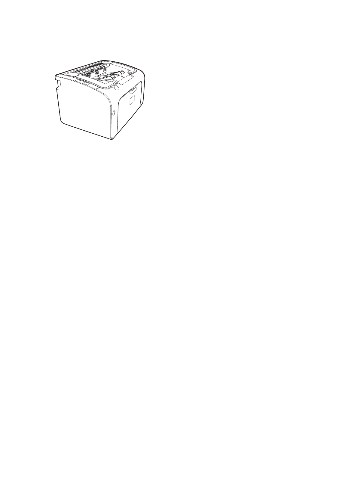
Figure 1-1 HP LaserJet P1000 Series
First Page Out: < 8 seconds
●
Speed: 14 A4 pages per minute (ppm), 15 Letter-size ppm.
●
Tray: 150 sheet universal tray.
●
Connectivity: Hi-Speed USB 2.0 port.
●
HP LaserJet P1006/P1008 only
First Page Out: < 8 seconds
●
Speed: 22 A4 pages per minute (ppm), 17 Letter-size ppm.
●
Tray: 10 sheet priority feed slot and a 150 sheet universal tray.
●
Connectivity: Hi-Speed USB 2.0 port.
●
2 Chapter 1 Product information ENWW

Product features
Benefit Supporting features
Excellent print quality
Ease of use
Flexible paper handling
Interface connections
Energy savings
Economical printing
HP print cartridges.
●
True 600 by 600 dots per inch (dpi) text and graphics.
●
Adjustable settings to optimize print quality.
●
The print cartridge is easy to install.
●
Convenient access to the print cartridge and to the paper path
●
through the cartridge door.
Adjust paper tray with one hand.
●
Main tray for letterhead, envelopes, labels, transparencies,
●
custom-sized media, postcards, and heavy paper.
Priority feed slot for letterhead, envelopes, labels,
●
transparencies, custom-sized media, postcards, and heavy
paper.
A 125-sheet top output bin.
●
Print on Both Sides (manually).
●
Hi-Speed 2.0 USB port.
●
The device automatically conserves electricity by
●
substantially reducing power consumption when it is not
printing.
N-up printing (printing more than one page on a sheet) and
●
Printing on Both Sides features save paper.
Archive printing
Supplies
Accessibility
Security
When printing pages that are to be stored long-term, this
●
option sets the device to a mode that reduces toner smearing
and dusting.
Select Archive as the paper type.
●
A Supplies Status page with print cartridge gauges that
●
estimate remaining supply level. Not available for non-HP
supplies.
No-shake cartridge design.
●
Authentication for original HP print cartridges.
●
Easy ordering for replacement supplies.
●
Online user guide compatible with text screen-readers.
●
All doors and covers can be opened with one hand.
●
Kensington lock receptacle on back of device.
●
ENWW Product features 3
Identify product parts
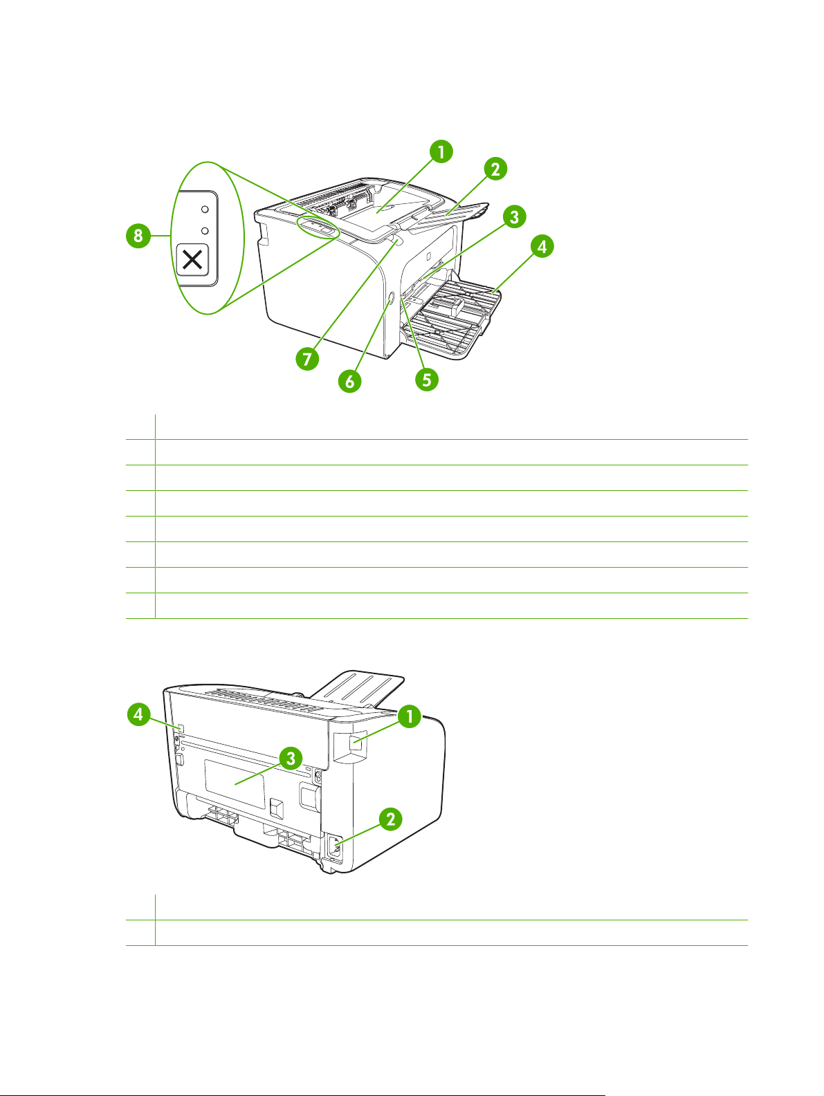
Figure 1-2 HP LaserJet P1000 Series, front view (HP LaserJet P1006/P1008 shown)
1 Output bin
2 Foldable Output Tray Extension
3 Priority feed slot (HP LaserJet P1006/P1008 only)
4 Foldable Main Input tray
5 Short Media Extender (HP LaserJet P1005/P1007 only)
6 Power button
7 Cartridge door lift-tab (access to print cartridge)
8 Control panel (HP LaserJet P1006/P1008 control panel shown)
Figure 1-3 HP LaserJet P1000 Series, back view (HP LaserJet P1006/P1008 shown)
1 USB Port (2.0)
2 Power receptacle
4 Chapter 1 Product information ENWW

3 Serial number
4 Kensington lock receptacle
ENWW Identify product parts 5

6 Chapter 1 Product information ENWW

2 Managing and maintenance
Replace the print cartridge
●
Printer information pages
●
Clean the device
●
Change the pickup roller
●
Clean the pickup roller
●
Change the printer separation pad
●
EconoMode
●
ENWW 7
Replace the print cartridge
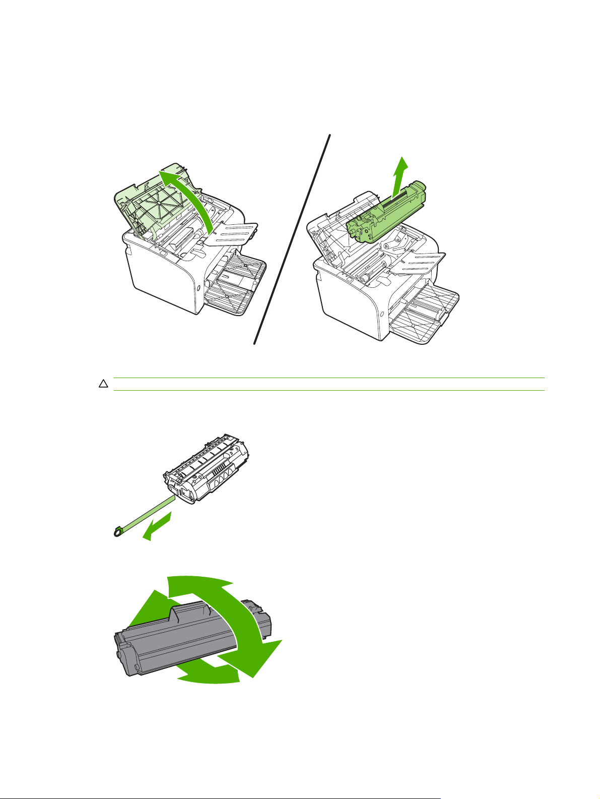
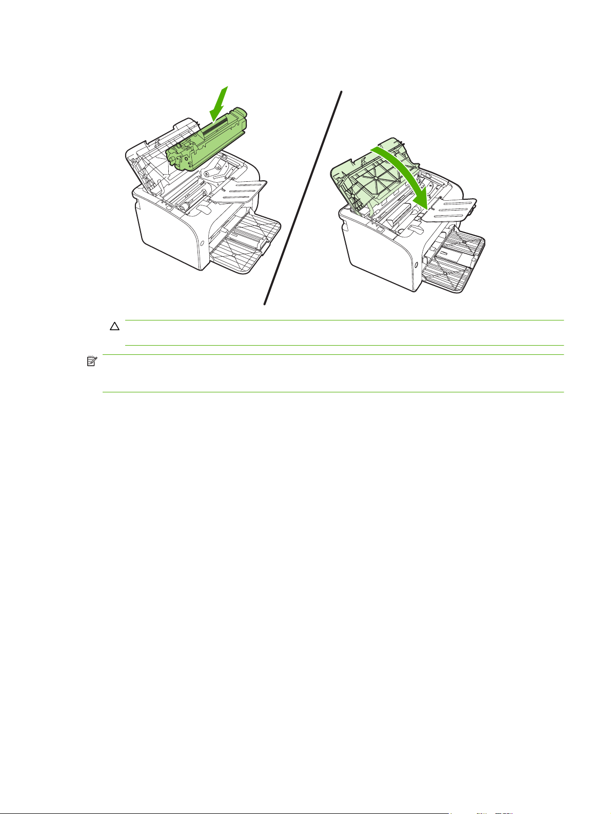
1. Open the print-cartridge door, and remove the old print cartridge. See the recycling information
inside the print-cartridge box. To prevent damage to the print cartridge, minimize its exposure to
direct light by covering it with a sheet of paper.
2. Remove the new print cartridge from the packaging.
CAUTION: To prevent damage to the print cartridge, hold the print cartridge at each end.
3. Pull the tab until all the tape is removed from the cartridge. Put the tab in the print-cartridge box to
return for recycling.
4. Gently rock the toner cartridge from front to back to distribute the toner evenly inside the cartridge.
8 Chapter 2 Managing and maintenance ENWW
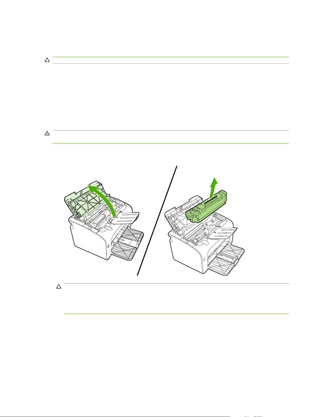
5. Insert the print cartridge in the device and close the print-cartridge door.
CAUTION: If toner gets on your clothing, wipe it off with a dry cloth and wash the clothing in cold
water. Hot water sets toner into the fabric.
NOTE: When toner is low, faded or light areas appear on the printed page. You might be able to
temporarily improve print quality by redistributing the toner. To redistribute the toner, remove the
cartridge from the device and gently rock it from front to back.
ENWW Replace the print cartridge 9

Printer information pages
You can print the following information pages. To print an information page, select it from the Print
Information Pages drop-down list on the Services tab in Printer Preferences.
10 Chapter 2 Managing and maintenance ENWW

Demo page
The Demo page contains examples of text and graphics.
ENWW Printer information pages 11

Configuration page
The Configuration page lists current settings and properties of the printer. It also contains a status log
report.
12 Chapter 2 Managing and maintenance ENWW
Clean the device
Clean the outside of the device with a clean, damp cloth when necessary.
CAUTION: Do not use ammonia-based cleaners on or around the device.
During the printing process, paper, toner, and dust particles can accumulate inside the device. Over
time, this buildup can cause print quality problems, such as toner specks or smearing, and paper jams.
To correct and prevent these types of problems, clean the print cartridge area and the device media
path.
Clean the print-cartridge area
You do not need to clean the print-cartridge area often. However, cleaning this area can improve the
quality of the printed sheets.
WARNING! Before cleaning the device, turn the device off by unplugging the power cord, and wait for
the device to cool.
1. Unplug the power cord from the device. Open the print-cartridge door, and remove the print
cartridge.
CAUTION: Do not touch the black-sponge transfer roller inside the device. Doing so can damage
the device.
CAUTION: To prevent damage, do not expose the print cartridge to light. Cover it with a piece
of paper.
ENWW Clean the device 13
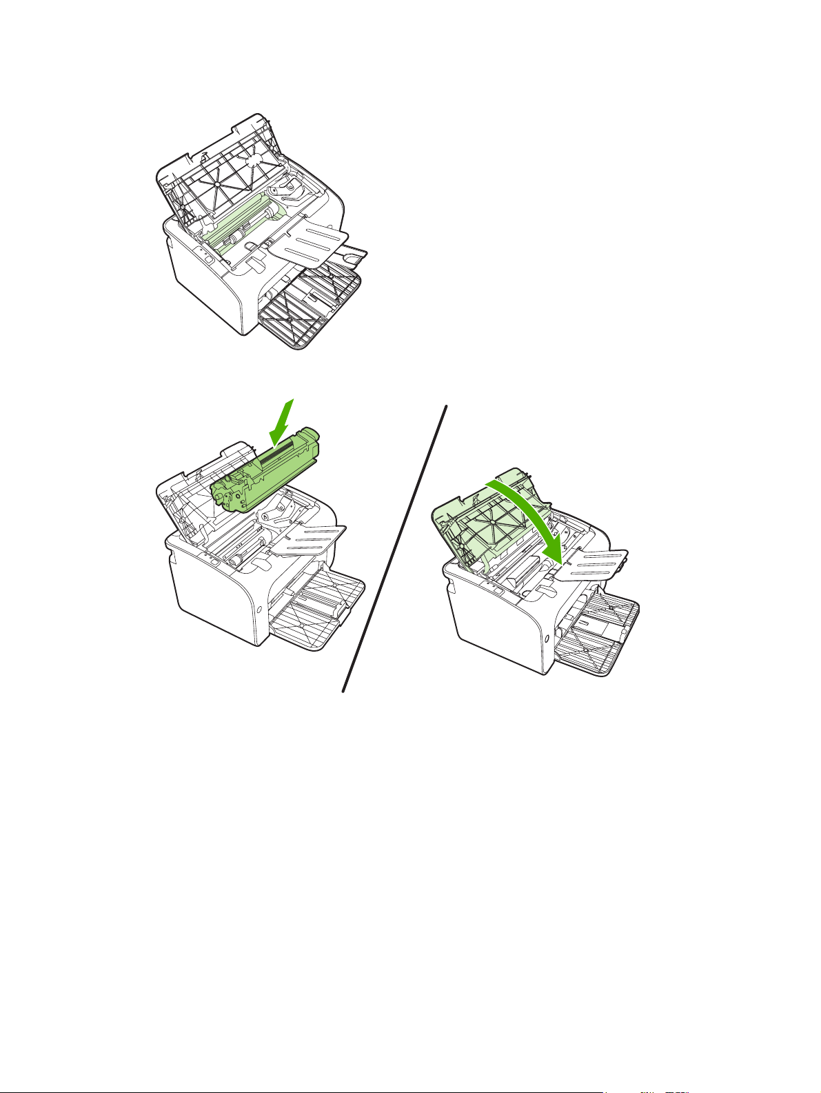
2. With a dry, lint-free cloth, wipe any residue from the paper-path area and the print-cartridge cavity.
3. Replace the print cartridge, and close the print-cartridge door.
14 Chapter 2 Managing and maintenance ENWW
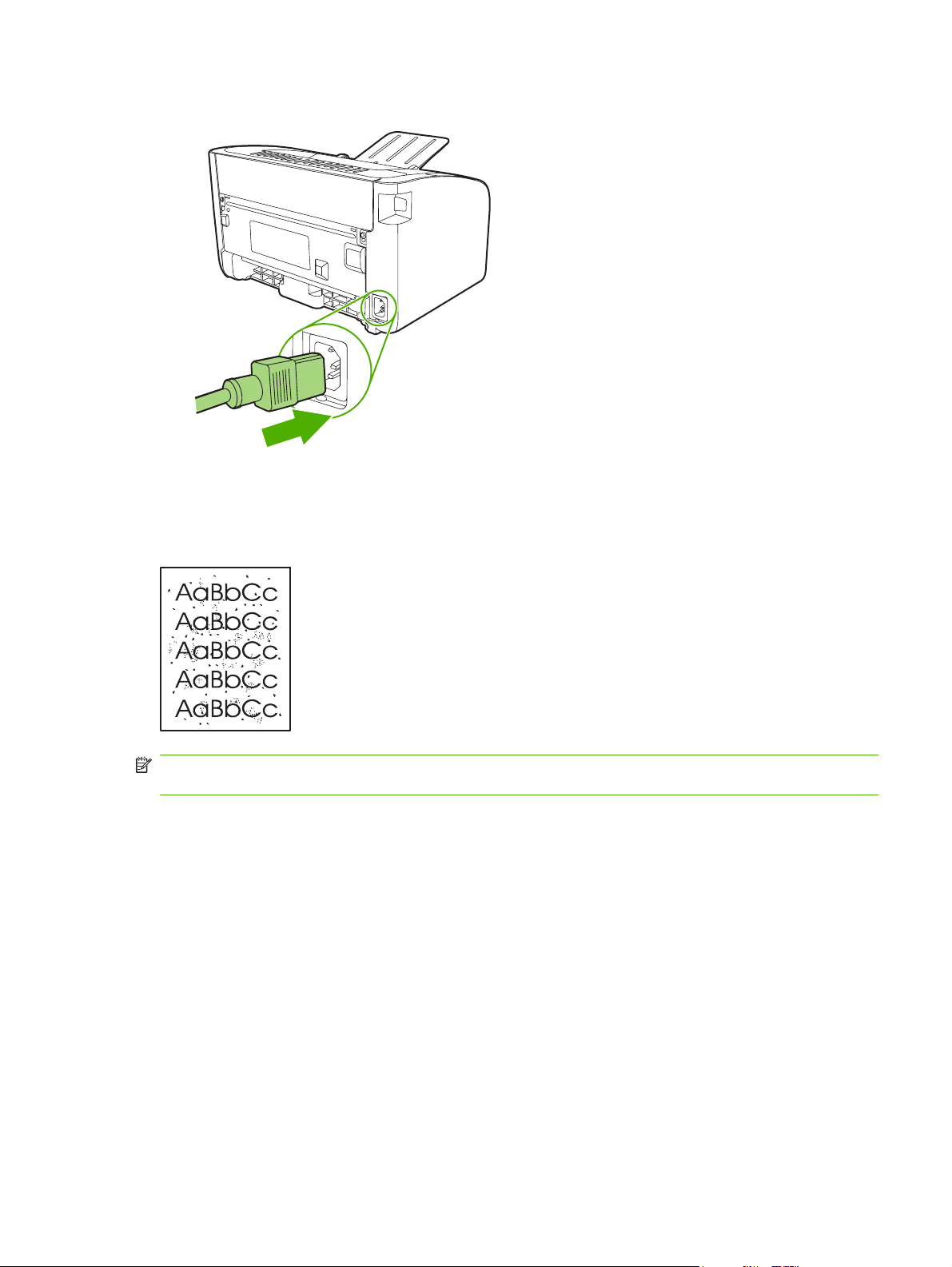
4. Plug the power cord into the device.
Clean the device paper path
If you are experiencing toner specks or dots on the printouts, clean the paper path. This process uses
a transparency to remove dust and toner from the paper path. Do not use bond or rough paper.
NOTE: For best results use a sheet of transparency. If you do not have any transparencies, you can
use copier-grade media (70 to 90 g/m
1. Make sure that the device is idle and the Ready light is on.
2. Load the media in the input tray.
ENWW Clean the device 15
2
(18 to 24 lb.)) that has a smooth surface.

3. Print a cleaning page. Access the printer Properties (or Printing Preferences in Windows 2000
and XP) then click on the Device Settings tab.
NOTE: The cleaning process takes approximately 2 minutes. The cleaning page will stop periodically
during the cleaning process. Do not turn the device off until the cleaning process has finished. You might
need to repeat the cleaning process several times to thoroughly clean the device.
16 Chapter 2 Managing and maintenance ENWW
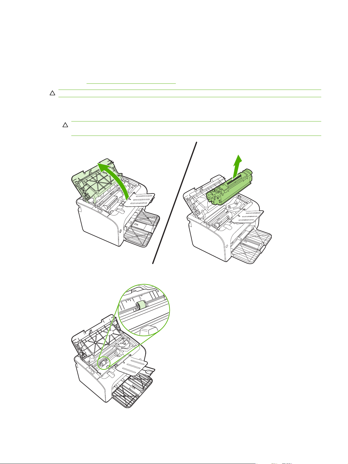
Change the pickup roller
Normal use with good media causes wear. The use of poor media might require more frequent
replacement of the pickup roller.
If the device regularly mispicks (no media feeds through), you might need to change or clean the pickup
roller. See
CAUTION: Failure to complete this procedure might damage the device.
1. Open the print-cartridge door, and remove the old print cartridge. See the recycling information
Clean the pickup roller on page 20 to order a new pickup roller.
inside the print-cartridge box.
CAUTION: To prevent damage to the print cartridge, minimize its exposure to direct light. Cover
the print cartridge with a sheet of paper.
2. Find the pickup roller.
ENWW Change the pickup roller 17
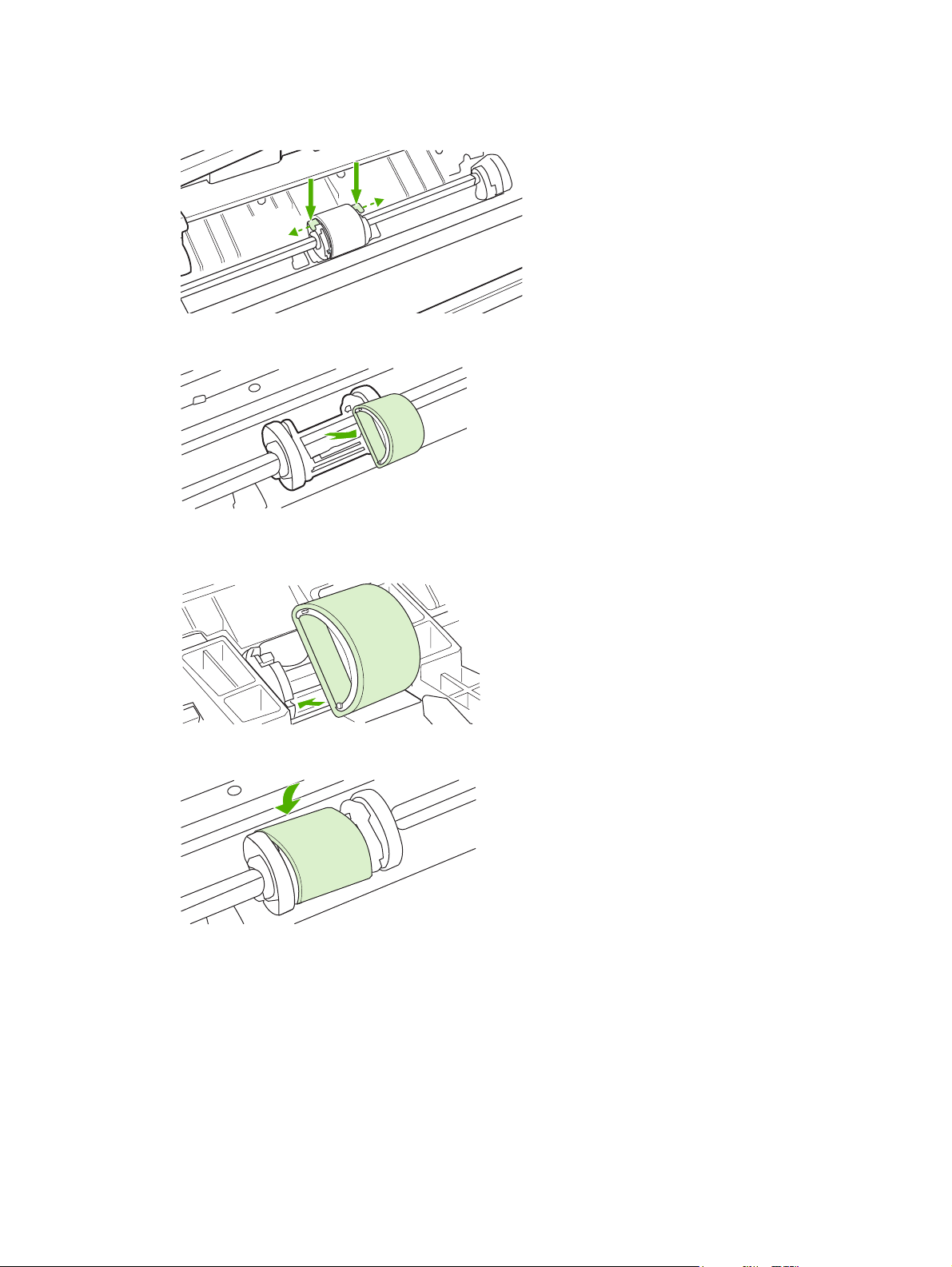
3. Release the small tabs on each side of the pickup roller, and rotate the pickup roller toward the
front.
4. Gently pull the pickup roller up and out.
5. Position the new pickup roller in the slot. The circular and rectangular slots on each side prevents
you from installing the roller incorrectly.
6. Rotate the top of the new pickup roller away from you until both sides snap into place.
18 Chapter 2 Managing and maintenance ENWW

7. Insert the print cartridge in the device and close the print-cartridge door.
ENWW Change the pickup roller 19

Clean the pickup roller
If you want to clean the pickup roller before deciding to replace it, follow these instructions:
1. Unplug the power cord from the device and remove the pickup roller as described in steps 1
through 5 of
2. Dab a lint-free cloth in isopropyl alcohol, and scrub the roller.
WARNING! Alcohol is flammable. Keep the alcohol and cloth away from an open flame. Before
you close the device and plug in the power cord, allow the alcohol to dry completely.
3. Using a dry, lint-free cloth, wipe the pickup roller to remove loosened dirt.
Change the pickup roller on page 17
4. Allow the pickup roller to dry completely before you reinstall it in the device.
5. Plug the power cord into the device.
20 Chapter 2 Managing and maintenance ENWW

Change the printer separation pad
Normal use with good media causes wear. The use of poor media might require more frequent
replacement of the separation pad.
If the device regularly pulls multiple sheets of media at a time, you might need to change the separation
pad.
NOTE: Before you change the separation pad, clean the pickup roller. See Clean the pickup roller
on page 20.
WARNING! Before changing the printer separation pad, turn the device off by unplugging the power
cord, and wait for the device to cool.
1. Unplug the device from the wall outlet.
2. Remove paper and close main input tray. Set device on its front.
3. At the bottom of the device, unscrew the two screws holding the separation pad in place.
ENWW Change the printer separation pad 21

4. Remove the separation pad.
5. Insert the new separation pad, and screw it into place.
22 Chapter 2 Managing and maintenance ENWW

6. Plug the device into the wall outlet, and turn on the device.
ENWW Change the printer separation pad 23

EconoMode
With EconoMode, the device uses less toner per page. Selecting this option can extend the life of the
print cartridge and reduce your cost per page. However, it also reduces print quality. The printed image
is lighter, but it is adequate for printing drafts or proofs.
HP does not recommend the full-time use of EconoMode. If EconoMode is used full-time, the toner
supply might outlast the mechanical parts in the print cartridge. If print quality begins to degrade under
these circumstances, you must install a new print cartridge even if toner remains in the cartridge.
1. To use EconoMode, open the printer Properties (or Printing Preferences in Windows 2000
and XP).
2. On the Paper/Quality tab or the Finishing tab (the Paper Type/Quality tab for some Mac drivers),
select the EconoMode check box.
NOTE: Not all printer features are available in all drivers or operating systems. See the printer
Properties (driver) online Help for information about availability of features for that driver.
24 Chapter 2 Managing and maintenance ENWW

3 Theory of operation
Introduction
●
Internal components
●
Timing
●
Engine control system
●
Laser/scanner system
●
Pickup/feed/delivery system
●
Image-formation system
●
ENWW 25

Introduction
This chapter presents an overview of the relationships between major components in the printer, and
includes a detailed discussion of the image-formation system. The following systems are discussed:
Engine control system
●
Laser/scanner system
●
Pickup/feed/delivery system
●
Image-formation system
●
Figure 3-1 Block diagram on page 26 illustrates the relationships among the four systems.
Figure 3-1 Block diagram
LASER/SCANNER SYSTEM
ENGINE CONTROL
SYSTEM
IMAGE-FORMATION SYSTEM
PICKUP-AND-FEED SYSTEM
26 Chapter 3 Theory of operation ENWW

Internal components
Figure 3-2 Cross-section of printer on page 27 highlights the major internal components.
Figure 3-2 Cross-section of printer
1 2 3 4 5
6
1 Fusing unit
2 Pressure roller
3 Delivery roller
4 Fusing film
5 Laser/scanner unit
6 Single-sheet-feed slot (HP LaserJet P1006/P1008 only)
7 Multi-purpose tray
8 Photosensitive drum
9 Pickup roller
10 Separation pad
11 Feed roller
12 Transfer roller
789101112
ENWW Internal components 27

Timing
Sequence of operation
Operation sequences are controlled by the microprocessor on the DC controller.
Table 3-1 Sequence
of operation on page 28 describes engine operations for each period of a print operation.
Table 3-1 Sequence of operation
Name Timing Purpose
WAIT From power-on until the end of the main motor initial
drive
STBY (standby) From the end of the WAIT or LSTR period until either
a print command is sent from the formatter or the
power is turned off.
INTR (initial
rotation)
PRINT From the end of the INTR period until the last page
LSTR (last
rotation)
From the time of the print command until the pickup
solenoid is turned on.
completes the fusing operation.
From the end of the PRINT period until the main
motor stops rotating.
Detects presence of a print cartridge. Clears potential
from the drum surface and cleans the transfer roller.
Prepares the printer to receive print commands
Prepares the photosensitive drum for printing.
Forms the image on the photosensitive drum and
transfers the toner image to the media.
Delivers the last page of a print job.
After LSTR, the printer either returns to STBY or, if
another print command was sent from the formatter,
enters INTR.
28 Chapter 3 Theory of operation ENWW

Engine control system
The engine control system coordinates all printer functions, according to commands sent from the
formatter. It drives the laser/scanner system, the image-formation system, and the pickup/feed/delivery
system.
The engine control system contains the following components:
DC controller
●
Low-voltage power supply
●
High-voltage power supply
●
Fusing control
●
Figure 3-3 Engine control system
ENGINE CONTROL SYSTEM
DC controller
LASER/SCANNER SYSTEM
Formatter
Low-voltage power supply
IMAGE-FORMATION SYSTEM
High-voltage power supply
PICKUP-AND-FEED SYSTEM
Fixing control
ENWW Engine control system 29

Figure 3-4 Engine control system circuit diagram
Engine controller
Fixing unit
AC input
Transfer roller
Cartridge
Formatter
Fixing control
Low-voltage
power supply
High-voltage
power supply
DC controller
M
Laser/scanner
Motor
Solenoid
Sensor
Switch
unit
30 Chapter 3 Theory of operation ENWW

Laser/scanner system
The laser/scanner system receives video signals from the dc controller and the formatter and converts
the signals into latent images on the photosensitive drum.
Figure 3-5 Laser/scanner system
BD sensor
Laser unit
Photosensitive drum
Four-faced mirror
BD INPUT signal
LASER CONTROL signal
VIDEO signal
Scanner motor unit
SCANNER MOTOR SPEED
CONTROL signal
Engine controller
Formatter
ENWW Laser/scanner system 31

Pickup/feed/delivery system
The pickup/feed/delivery system consists of several types of feed rollers and sensors. The dc controller
uses two motors and two solenoids to drive the rollers. Three media-detection sensors detect media as
it passes through the printer. If media does not reach or pass each sensor within a specified time period,
the dc controller determines that a jam has occurred and alerts the formatter.
The following components are identified in
M1, main motor
●
SL1, pickup solenoid
●
PS701, fuser delivery sensor
●
PS702, media-width sensor
●
PS751, top-of-page sensor
●
Figure 3-6 Pickup/feed/delivery system
Pressure roller
PS702
Feed roller
PS701
Fixing sleeve
Photosensitive drum
Figure 3-6 Pickup/feed/delivery system on page 32:
Transfer roller
PS751
SL1
Separation pad
Pickup roller
M1
Single-sheet-feed tray
Multi-purpose tray
32 Chapter 3 Theory of operation ENWW

Image-formation system
Laser printing requires the interaction of several different technologies, including electronics, optics, and
electrophotographics, to provide a printed page. Each process functions independently and must be
coordinated with the other printer processes. Image formation consists of the following five
processes:
electrostatic latent-image formation
●
developing
●
transfer
●
fusing
●
drum cleaning
●
The five processes contain eight steps.
Figure 3-7 Image-formation system
Step 1: Primary charging
The DC bias is applied to the primary charging roller, which transfers a uniform negative potential to the
photosensitive drum.
Figure 3-8 Primary charging
Primary charging roller
DC bias
Photosensitive drum
ENWW Image-formation system 33

Step 2: Laser beam exposure
The laser beam scans the photosensitive drum to neutralize negative charges on parts of the drum. An
electrostatic latent image is formed on the drum where negative charges were neutralized.
Figure 3-9 Laser beam exposure
Unexposed area Exposed area
Step 3: Developing
The toner acquires a negative charge from the friction that occurs when the developing cylinder rotates
against the developing blade. When the negatively charged toner comes in contact with the drum, it
adheres to the electrostatic latent image because the drum surface has a higher potential. The image
on the drum becomes visible because of the toner. The AC bias that is superimposed over the develping
negative DC bias is applied to the developing cylinder.
Laser beam
Figure 3-10 Developing
Blade
Exposed area
Unexposed area
Developing cylinder
Photosensitive drum
Unexposed area
Exposed area
AC bias
DC bias
34 Chapter 3 Theory of operation ENWW

Step 4: Transfer
The positive DC bias is applied to the transfer roller. As the media passes between the transfer roller
and the photosensitive drum, the transfer roller applies a positive DC bias to the media. The positively
charged media attracts the negatively charged toner from the drum surface.
Figure 3-11 Transfer
Transfer roller
Step 5: Separation
The elasticity of the print media causes its separation from the photosensitive drum. A static charge
eliminator aids separation by weakening any electrostatic adhesion.
Photosensitive
drum
Media
DC bias
Figure 3-12 Separation
Static charge eliminator
Photosensitive
drum
Media
Transfer roller
ENWW Image-formation system 35

Step 6: Fusing
The printer uses the on-demand fusing method to permanently fuse the toner image to the media using
heat and pressure.
Figure 3-13 Fusing
Fixing heater
Step 7: Drum cleaning
The cleaning blade scrapes the residual toner off the photosensitive drum and deposits it into the waste
toner case.
Figure 3-14 Drum cleaning
Cleaning blade
Fixing film
Toner
Media
Pressure roller
Waste toner container
Photosensitive
drum
36 Chapter 3 Theory of operation ENWW

4 Removal and replacement
Introduction
●
Before performing service
●
Covers
●
Formatter
●
Fuser
●
Laser/scanner
●
DC controller
●
Transfer roller
●
Motor drive belt
●
Rear paper-feed roller
●
Main motor
●
ENWW 37

Introduction
This chapter documents removal and replacement of field replaceable units (FRUs) only.
Removal and replacement strategy
Replace parts in the reverse order of their removal. Directions for difficult or critical replacement
procedures are included.
WARNING! The sheet-metal edges of the product can be sharp. Use caution when working on the
product.
NOTE: Note the length, diameter, color, type, and location of each screw. Be sure to return each screw
to its original location during reassembly.
Incorrectly routed or loose wire harnesses can interfere with other internal components and can become
damaged or broken. Frayed or pinched harness wires can be difficult to locate. When replacing wire
harnesses, always use the provided wire loops, lance points, or wire-harness guides.
Electrostatic discharge
CAUTION: The product contains parts that are sensitive to electrostatic discharge (ESD). Always
service the product at an ESD-protected workstation, or use an ESD mat.
Watch for the ESD symbol to identify the parts that are sensitive to ESD. Protect these parts by using
an ESD wrist strap and by placing ESD-sensitive parts into protective ESD pouches.
Required tools
The following tools are needed to service this product:
#2 Phillips screwdriver with magnetic tip
●
Small flat-blade screwdriver
●
Small needle-nose pliers
●
ESD mat
●
Penlight
●
CAUTION: A pozidrive screwdriver can damage the screw heads on the product. Use a #2 Phillips
screwdriver.
If you use a multispeed screwdriver, use a torque limiter.
38 Chapter 4 Removal and replacement ENWW

Before performing service
Follow the pre-service procedures before you perform service.
Pre-service procedures
1. Remove all media from the product.
2. Place the product on an ESD mat. If an ESD mat or an ESD-protected workstation is not available,
discharge body static and ground the product chassis before servicing the product.
3. Remove the print cartridge.
4. Unplug the power cord and the interface cable.
Parts removal order
Use the following diagram to determine which parts must be removed before removing other parts.
ENWW Before performing service 39

Covers
Front Cover
1. Turn the device over so that it is resting on its back.
2. Using a flat-blade screwdriver, lift the plastic edges of the front cover out of their sockets (callout
1) and rotate the cover back.
Figure 4-1 Remove front cover (1 of 1)
Control panel
1. Remove the front cover. See Front Cover on page 40.
2. Remove control panel cover by prying up the leading edge, then sliding it towards the front of the
printer and lifting it out.
40 Chapter 4 Removal and replacement ENWW

3. Remove light-pipe (callout 1) and button (callout 2).
NOTE: The button (callout 2) is only present on the HP LaserJet P1006/P1008 and does not
need to be removed from the HP LaserJet P1005/P1007.
Figure 4-2 Remove control panel (1 of 1)
Side Covers
1. Remove the front cover. See Front Cover on page 40.
2. Remove the control panel. See
3. Remove two screws (callout 1).
Figure 4-3 Remove side covers (1 of 4)
Control panel on page 40.
ENWW Covers 41

4. Turn the device on its left side. Remove the right side cover by using a small flat blade screwdriver
to lift it out of the socket. A small arrow in the plastic indicates where the leverage should be applied.
Rotate the cover towards the front of the device and remove it.
Figure 4-4 Remove side covers (2 of 4)
42 Chapter 4 Removal and replacement ENWW

5. Turn the device on its right side. There are three catches that must be released. Use a small flat
blade screwdriver to release the catch on the back of the printer (callout 1) and the bottom of the
printer (callout 2). Then open the top of the printer and release the catch on the inside (callout 3).
Once all three catches are released, rotate the cover towards the front of the device and remove
it.
Figure 4-5 Remove side covers (3 of 4)
Figure 4-6 Remove side covers (4 of 4)
Back Cover
1. Remove the front cover. See Front Cover on page 40.
2. Remove the control panel. See
3. Remove both side covers. See
ENWW Covers 43
Control panel on page 40.
Side Covers on page 41.

4. Remove one grounding screw (callout 1).
Figure 4-7 Remove back cover (1 of 2)
5. Lift plate in three of the four corners (callout 2) to pop the plate off. Use a small flat blade screwdriver
to get leverage on each of the corners.
Top Cover
1. Remove the front cover. See Front Cover on page 40.
Figure 4-8 Remove back cover (2 of 2)
2. Remove the control panel. See
3. Remove both side covers. See
4. Remove the back cover. See
44 Chapter 4 Removal and replacement ENWW
Control panel on page 40.
Side Covers on page 41.
Back Cover on page 43.

5. Separate the tabs (callout 1) and lift the top cover off of the device.
Figure 4-9 Remove top cover (1 of 1)
NOTE: There are two link arms that slide through slots in the top cover. They are disengaged
when the cover is removed. Be sure to feed the link arms back through the slots when reinstalling
the top cover.
ENWW Covers 45

Formatter
1. Remove the front cover. See Front Cover on page 40.
2. Remove the control panel. See
3. Remove the left side cover. See
4. Remove four screws (callout 1) and unplug the cable (callout 2).
Figure 4-10 Remove formatter (1 of 2)
Control panel on page 40.
Side Covers on page 41.
5. Remove the formatter board.
Figure 4-11 Remove formatter (2 of 2)
NOTE: When reinstalling the formatter board, place the board on the support bracket first and
align holes before attaching it with the screws.
46 Chapter 4 Removal and replacement ENWW

Fuser
1. Remove the front cover. See Front Cover on page 40.
2. Remove the control panel. See
3. Remove both side covers. See
4. Remove the back cover. See
5. Remove the top cover. See
6. Unplug and unthread the red wire from the retaining clips (callout 1).
Figure 4-12 Remove fuser (1 of 6)
Control panel on page 40.
Side Covers on page 41.
Back Cover on page 43.
Top Cover on page 44.
ENWW Fuser 47

7. Unplug the power connector (callout 2). Unplug the remaining three connectors (callout 3).
Figure 4-13 Remove fuser (2 of 6)
NOTE: When removing the thin two-wire connector on the left, use a small flat-blade screwdriver
to flex out the left side of the cable socket so that the cable comes free without damaging the cable
or the socket.
8. Unthread the wires from the retaining clips in the rear of the device.
Figure 4-14 Remove fuser (3 of 6)
48 Chapter 4 Removal and replacement ENWW

9. Remove the black plastic cable guide from the rear of the device (callout 4). Use a tool to push on
the tab from the left as indicated.
Figure 4-15 Remove fuser (4 of 6)
10. Remove three screws from top of device (callout 5).
Figure 4-16 Remove fuser (5 of 6)
ENWW Fuser 49

11. Remove the fuser assembly.
Figure 4-17 Remove fuser (6 of 6)
NOTE: To reinstall the fuser, the notches on either side of the fuser must slide into the groves on
the inside of the cartridge bay.
50 Chapter 4 Removal and replacement ENWW

Laser/scanner
1. Remove the front cover. See Front Cover on page 40.
2. Remove the control panel. See
3. Remove both side covers. See
4. Remove the top cover. See
5. Remove four screws (callout 1).
Figure 4-18 Remove laser/scanner (1 of 4)
Control panel on page 40.
Side Covers on page 41.
Top Cover on page 44.
ENWW Laser/scanner 51

6. Remove the scanner cover from the device.
Figure 4-19 Remove laser/scanner (2 of 4)
NOTE: When reinstalling the cover, feed the lever through the plastic slot in the top of the cover.
7. Unplug two cables (callout 2) and remove four screws (callout 3).
Figure 4-20 Remove laser/scanner (3 of 4)
52 Chapter 4 Removal and replacement ENWW

8. Remove the laser/scanner
Figure 4-21 Remove laser/scanner (4 of 4)
ENWW Laser/scanner 53

DC controller
1. Remove the front cover. See Front Cover on page 40.
2. Remove the control panel. See
3. Remove the left side cover. See
4. Remove the fuser. See
5. Remove three screws from the metal plate (callout 1). Remove the metal plate.
Figure 4-22 Remove DC controller (1 of 4)
Fuser on page 47.
Control panel on page 40.
Side Covers on page 41.
6. Remove the black plastic crossmember (callout 2) by lifting up on the left tab.
Figure 4-23 Remove DC controller (2 of 4)
54 Chapter 4 Removal and replacement ENWW

7. Unplug three cables (callout 3).
Figure 4-24 Remove DC controller (3 of 4)
8. Remove two screws from the rear of the device (callout 4) and remove three screws from the DC
controller board (callout 5).
Figure 4-25 Remove DC controller (4 of 4)
9. Remove the DC Controller board.
ENWW DC controller 55

Transfer roller
1. Open the top cover and remove the print cartridge.
2. Pinch the white plastic clip on the right side of the transfer roller to release the roller (callout 1).
Slide the roller to the right and remove it.
NOTE: Do not touch the pad on the transfer roller.
Figure 4-26 Remove transfer roller (1 of 1)
56 Chapter 4 Removal and replacement ENWW

Motor drive belt
1. Remove the front cover. See Front Cover on page 40.
2. Remove the right side cover. See
3. Turn the device up on its left side and remove four screws (callout 1).
Figure 4-27 Remove motor drive belt (1 of 4)
Side Covers on page 41.
4. Remove the gear cover plate.
Figure 4-28 Remove motor drive belt (2 of 4)
ENWW Motor drive belt 57

5. Remove three loose gears (callout 2).
Figure 4-29 Remove motor drive belt (3 of 4)
6. Pinch the drive belt and carefully slide it off the drive gear.
2
Figure 4-30 Remove motor drive belt (4 of 4)
58 Chapter 4 Removal and replacement ENWW

Rear paper-feed roller
1. Remove the front cover. See Front Cover on page 40.
2. Remove the control panel. See
3. Remove both side covers. See
4. Remove the back cover. See
NOTE: While it is possible to remove the rear paper feed roller without removing the gear plate
on the right side of the printer, the process is easier if the plate has been removed. Follow steps 1
through 4 for removing the motor drive belt to remove the gear plate. See
on page 57.
5. Remove black cartridge sensor rod by detaching the right side of the rod from the clip and sliding
it to the right (callout 1). Be careful not to lose attached spring
Figure 4-31 Remove rear paper feed roller (1 of 3)
Control panel on page 40.
Side Covers on page 41.
Back Cover on page 43.
Motor drive belt
NOTE: When reinserting the sensor rod, make sure the left tab feeds into the slot in the rear of
the device. Wind the spring an extra revolution before attaching to ensure proper tension.
6. There are two roller catches on either side of the roller pads that are locked in place with tabs. Lift
up the inside tabs of the two roller catches and slide them away from the roller pads. Remove them
from the device.
ENWW Rear paper-feed roller 59

7. Release the gear at the left end of the roller by pinching the tab inside the gear housing. Slide the
gear away from the roller.
Figure 4-32 Remove rear paper feed roller (2 of 3)
8. Slide the roller away from the drive gear and out of the back of the device.
Figure 4-33 Remove rear paper feed roller (3 of 3)
60 Chapter 4 Removal and replacement ENWW

Main motor
1. Remove the front cover. See Front Cover on page 40.
2. Remove the control panel. See
3. Remove both side covers. See
4. Remove the back cover. See
5. Remove the top cover. See
6. Remove the laser/scanner. See
NOTE: You only need to follow the steps in the Laser/scanner section until the scanner cover is
removed (step six). It is not necessary to remove the entire laser/scanner assembly in order to
access the main motor.
7. Unplug two cables (callout 1).
Figure 4-34 Remove main motor (1 of 5)
Control panel on page 40.
Side Covers on page 41.
Back Cover on page 43.
Top Cover on page 44.
Laser/scanner on page 51.
1
ENWW Main motor 61

8. Pinch and remove motor-control card (it will hang by a soldered ribbon cable). Unthread the wire
from the plastic bracket and remove one screw (callout 2).
Figure 4-35 Remove main motor (2 of 5)
62 Chapter 4 Removal and replacement ENWW

9. Remove the plastic bracket.
Figure 4-36 Remove main motor (3 of 5)
ENWW Main motor 63

10. Remove two screws (callout 3).
Figure 4-37 Remove main motor (4 of 5)
64 Chapter 4 Removal and replacement ENWW

11. Remove the main motor.
Figure 4-38 Remove main motor (5 of 5)
ENWW Main motor 65

66 Chapter 4 Removal and replacement ENWW

5 Problem solving
Problem-solving checklist
●
Contact HP support
●
Status-light patterns
●
Clearing jams
●
Improve print quality
●
Media problem-solving
●
Printed page is different from what appeared on screen
●
Printer software problems
●
Common Macintosh problems
●
Network-setup problem-solving
●
ENWW 67

Problem-solving checklist
Step 1: Is the device set up correctly?
Is the device plugged into a power outlet that is known to work?
●
Is the on/off switch in the on position?
●
Is the print cartridge properly installed? See
●
Is paper properly loaded in the input tray?
●
Yes If you answered yes to the questions above, go to Step 2: Is
No If the device will not turn on, Contact HP support
Step 2: Is the Ready light on?
Verify that the Ready light (1) is illuminated on the control panel.
Yes Go to Step 3: Can you print an engine test page?
Replace the print cartridge on page 8.
the Ready light on? on page 68
on page 70.
on page 68
No If the control panel lights do not look like the picture above, see
Status-light patterns on page 71.
If you are unable to resolve the problem,
on page 70.
Contact HP support
Step 3: Can you print an engine test page?
To print an engine test page, open and close the cartridge door five times while the printer is in ready
mode. The printer should print one page with multiple horizontal lines.
Yes If the engine test page printed, go to Step 4: Is the device
communicating with the computer? on page 69
No If no paper came out, see Media problem-solving
on page 80.
If you are unable to resolve the problem,
on page 70.
68 Chapter 5 Problem solving ENWW
Contact HP support

Step 4: Is the device communicating with the computer?
Try printing a document from a software application.
Yes If the document prints, go to Step 5: Does the printed page look
like you expected? on page 69
No If the document does not print, see Printer software problems
on page 83.
If you are using a Macintosh computer, see
Macintosh problems on page 84.
If you are unable to resolve the problem,
on page 70.
Step 5: Does the printed page look like you expected?
Yes The problem should be resolved. If it is not resolved, Printed
page is different from what appeared on screen
on page 81.
No If the print quality is poor, see Improve print quality
on page 76.
Verify that the print settings are correct for the media you are
using.
If you are unable to resolve the problem,
on page 70.
Common
Contact HP support
Contact HP support
ENWW Problem-solving checklist 69

Contact HP support
In the United States, see
●
In other locations, see
●
http://www.hp.com/support/ljp1000 for the HP LaserJet P1000 Series
http://www.hp.com/.
70 Chapter 5 Problem solving ENWW

Status-light patterns
Table 5-1 Status-light legend
Symbol for "light off"
Symbol for "light on"
Symbol for "light blinking"
Table 5-2 Control-panel light messages
HP LaserJet P1000 Series light status State of the device Action
Initialization/Startup
HP LaserJet P1000 Series: During
Startup, the Go and Ready lights cycle (at
the rate of 500 ms) one after another.
HP LaserJet P1500 Series: While in the
Startup state, the Go, Ready, and
Attention lights cycle (at the rate of
500 ms) one after another.
Reconfiguration Initialization: During
the device start up, you can request
special initialization sequences that
reconfigure the device. The lights then
cycle as in the Initialization Startup state.
Job Cancel
After the cancellation process is
complete, the device returns to the Ready
state.
During the Initialization and Job Cancel
processes, pressing buttons has no
effect.
ENWW Status-light patterns 71

Table 5-2 Control-panel light messages (continued)
HP LaserJet P1000 Series light status State of the device Action
Ready
The device is ready with no job activity.
Processing Data
The device is processing or receiving
data.
Manual Feed or Continuable Error
This state occurs in the following
circumstances:
Manual feed
●
General continuable error
●
To print a Configuration page, press and
release the Go button (HP LaserJet
P1500 network models only).
To cancel the current job, press the
Cancel button (HP LaserJet P1006/
P1008/P1500 Series only).
To recover from the error and print the
available data, press the Go button
(HP LaserJet P1500 Series only).
If the recovery is successful, the device
continues to the Processing Data state
and completes the job.
If the recovery is unsuccessful, the
device continues to the Continuable
Error state. Try removing any media from
the media path and cycling the device
power.
Attention
Print-cartridge door is open
●
Paper jam
●
No cartridge installed
●
Paper out
●
Fatal Error
The device has encountered a nonrecoverable error.
Close the print-cartridge door, remove
the paper jam, install the cartridge, or
add paper.
Turn off the device, wait 10
●
seconds, and turn on the device.
If you cannot resolve the problem,
●
see
Contact HP support
on page 70.
72 Chapter 5 Problem solving ENWW

Clearing jams
Occasionally, media becomes jammed during a print job. You are notified through the control panel
lights.
The following are some of the causes of jams:
The input trays are loaded incorrectly or are too full.
●
NOTE: When you add new media, always remove all of the media from the input tray and
straighten the entire stack. This helps prevent multiple feeds and reduces media jams.
The media does not meet HP specifications.
●
The device might need to be cleaned to remove paper dust and other particles from the paper path.
●
Loose toner might remain in the device after a media jam. This toner clears up after a few sheets print.
CAUTION: If you get any toner on your clothes, wash them in cold water. Hot water will permanently
set the toner into the fabric.
Typical media jam locations
Print cartridge area: See
●
Input tray areas: If the page is still sticking out of the input tray, gently try to remove it from the
●
input tray without tearing the page. If you feel resistance, see
on page 73.
Output path: If the page is sticking out of the output bin, see
●
on page 73.
NOTE: Loose toner might remain in the device after a media jam. This toner clears up after a few
sheets are printed.
Removing a jammed page
CAUTION: Media jams might result in loose toner on the page. If you get any toner on your clothes,
wash them in cold water. Hot water will permanently set the toner into the fabric.
Removing a jammed page on page 73.
Removing a jammed page
Removing a jammed page
ENWW Clearing jams 73

To clear a jam in the print-cartridge area
CAUTION: Do not use sharp objects, such as tweezers or needle-nose pliers, to remove jams.
Damage they cause is not covered by the warranty.
1. Open the print-cartridge door, and then remove the print cartridge from the device.
CAUTION: To prevent damage to the print cartridge, minimize its exposure to direct light.
2. With both hands, grasp the side of the media that is most visible (this includes the middle), and
carefully pull it free from the device.
74 Chapter 5 Problem solving ENWW

3. Replace the print cartridge, and close the print-cartridge door.
NOTE: When you add new media, remove all the media from the input tray and straighten the
entire stack.
ENWW Clearing jams 75

Improve print quality
This section provides information about identifying and correcting print defects.
NOTE: If these steps do not correct the problem, contact an HP-authorized dealer or service
representative.
Light print or faded
Toner specks
The print cartridge is nearing end of life.
●
The media might not meet Hewlett-Packard's media
●
specifications (for example, the media is too moist or too
rough).
If the whole page is light, the print density adjustment is
●
too light or EconoMode might be turned on. Adjust the
print density, and disable EconoMode in the printer
Properties.
The media might not meet Hewlett-Packard's media
●
specifications (for example, the media is too moist or too
rough).
Dropouts
The device might need to be cleaned. See
●
device on page 13
A single sheet of media might be defective. Try reprinting
●
the job.
The media moisture content is uneven or the media has
●
moist spots on its surface. Try printing with new media.
The media lot is bad. The manufacturing processes can
●
cause some areas to reject toner. Try a different type or
brand of media.
The print cartridge might be defective.
●
Clean the
76 Chapter 5 Problem solving ENWW

Vertical lines
Gray background
The photosensitive drum inside the print cartridge has probably
been scratched. Install a new HP print cartridge. See
the print cartridge on page 8.
Make sure that tray 1 is in place.
●
Decrease the print density setting through the embedded
●
Web server. This decreases the amount of background
shading.
Change the media to a lighter basis weight.
●
Check the device environment. Very dry (low humidity)
●
conditions can increase the amount of background
shading.
Replace
Toner smear
Install a new HP print cartridge. See
●
cartridge on page 8.
If toner smears appear on the leading edge of the media,
●
the media guides might be dirty. Wipe the media guides
with a dry, lint-free cloth
Check the media type and quality.
●
Try installing a new HP print cartridge. See
●
print cartridge on page 8.
The fuser temperature might be too low. In your printer
●
driver, make sure the appropriate media type is selected.
Replace the print
Replace the
ENWW Improve print quality 77

Loose toner
Vertical repetitive defects
Clean the inside of the device. See
●
on page 13.
Check the media type and quality.
●
Try installing a new HP print cartridge. See
●
print cartridge on page 8].
In your printer driver, make sure the appropriate media
●
type is selected.
Plug the device directly into an AC outlet instead of into
●
a power strip or surge protector.
The print cartridge might be damaged. If a repetitive mark
●
occurs at the same spot on the page, install a new
HP print cartridge. See
on page 8.
The internal parts might have toner on them. If the defects
●
occur on the back of the page, the problem will probably
correct itself after a few more printed pages.
In your printer driver, make sure the appropriate media
●
type is selected.
Replace the print cartridge
Clean the device
Replace the
Misformed characters
Page skew
If characters are improperly formed, producing hollow
●
images, the media stock might be too slick. Try a different
media.
If characters are improperly formed, producing a wavy
●
effect, the device might need service. Print a
configuration page. If the characters are improperly
formed, contact an HP-authorized dealer or service
representative. See
Make sure that the media is loaded correctly and the
●
media guides are not too tight or too loose against the
media stack.
The input bin might be too full.
●
Check the media type and quality.
●
Contact HP support on page 70.
78 Chapter 5 Problem solving ENWW

Curl or wave
Wrinkles or creases
Check the media type and quality. Both high temperature
●
and humidity cause media to curl.
The media might have been in the input tray too long.
●
Turn over the stack of media in the tray. Also, try rotating
the media 180° in the input tray.
The fuser temperature might be too high. In your printer
●
driver, make sure the appropriate media type is selected.
If the problem persists, select a media type that uses a
lower fuser temperature, such as transparencies or light
media.
Make sure that media is loaded properly.
●
Check the media type and quality.
●
Turn over the stack of media in the tray. Also, try rotating
●
the media 180° in the input tray.
For envelopes, this can be caused by air pockets inside
●
the envelope. Remove the envelope, flatten the
envelope, and try printing again.
Toner-scatter outline
If large amounts of toner have scattered around the
●
characters, the media might be resisting the toner. (A
small amount of toner scatter is normal for laser printing.)
Try a different media type.
Turn over the stack of media in the tray.
●
Use media designed for laser printers.
●
ENWW Improve print quality 79

Media problem-solving
The following problems with media cause print-quality deviations, jamming, or damage to the device.
Problem Cause Solution
Poor print quality or toner adhesion The paper is too moist, too rough, too
heavy or too smooth, or it is embossed
or from a faulty paper lot.
Dropouts, jamming, or curl The paper has been stored incorrectly. Store paper flat in its moisture-proof
The paper has variability from one side
to the other.
Excessive curl The paper is too moist, has the wrong
grain direction, or is of short-grain
construction
The paper varies from side-to-side. Turn the paper over.
Jamming, damage to device The paper has cutouts or perforations. Use paper that is free of cutouts or
Problems with feeding The paper has ragged edges. Use high-quality paper that is made for
The paper varies from side-to-side. Turn the paper over.
The paper is too moist, too rough, too
heavy or too smooth, has the wrong grain
direction, or is of short-grain construction
or it is embossed or from a faulty paper
lot.
Print is skewed (crooked). The media guides might be incorrectly
adjusted.
Try another kind of paper, between 100
and 250 Sheffield, with 4% to 6%
moisture content.
wrapping.
Turn the paper over.
Use long-grain paper.
perforations.
laser printers.
Try another kind of paper, between 100
and 250 Sheffield, 4% to 6% moisture
content.
Use long-grain paper.
Remove all media from the input tray,
straighten the stack, and then load the
media in the input tray again. Adjust the
media guides to the width and length of
the media that you are using and try
printing again.
More than one sheet feeds at one time. The media tray might be overloaded. Remove some of the media from the tray.
The device does not pull media from the
media input tray.
The media might be wrinkled, folded, or
damaged.
The device might be in manual-feed
mode.
The pickup roller might be dirty or
damaged.
The paper-length adjustment control in
main tray is set at a length that is greater
than the media size.
Verify that the media is not wrinkled,
folded, or damaged. Try printing on
media from a new or different package.
Verify that the device is not in manual
feed mode and print your job again.
Contact HP Customer Care. See Contact
HP support on page 70or the support
flyer that came in the box.
Adjust the paper-length adjustment
control to the correct length.
80 Chapter 5 Problem solving ENWW

Printed page is different from what appeared on screen
Garbled, incorrect, or incomplete text
The wrong printer driver might have been selected when the software was installed. Make sure
●
that the correct printer driver is selected in the printer Properties.
If a specific file prints garbled text, a problem might exist with that specific file. If a specific
●
application prints garbled text, a problem might exist with that application. Make sure that the
appropriate printer driver is selected.
A problem might exist with your software application. Try printing from another software application.
●
The USB cable might be loose or defective.
●
Disconnect the cable and reconnect it at both ends.
◦
Try printing a job that you know works.
◦
If possible, attach the cable and device to another computer, and try printing a job that you
◦
know works.
Try using a new USB 2.0 cable that is 3 m (10 ft) or less in length.
◦
Turn off the device and the computer. Remove the USB cable, and inspect both ends of the
◦
cable for damage. Reconnect the cable, making sure that the connections are tight. Make
sure that the device is directly connected to the computer. Remove any switchboxes, tape
backup drives, security keys, or any other devices that are attached between the USB port
on the computer and the device. These devices can sometimes interfere with communication
between the computer and the device. Restart the device and the computer.
Missing graphics or text, or blank pages
Make sure that your file does not contain blank pages.
●
The sealing tape might still be in the print cartridge. Remove the print cartridge, and pull the tab
●
on the end of the cartridge until the entire length of the tape is removed. Reinstall the print cartridge.
Replace the print cartridge on page 8 for instructions. To check the device, print a configuration
See
page. See
The graphic settings in the printer Properties might not be correct for the type of job that you are
●
printing. Try a different graphic setting in the printer Properties.
Clean the device, particularly the contacts between the print cartridge and the power supply.
●
Configuration page on page 12 for instructions on how to print a configuration page.
Page format is different than on another HP LaserJet printer
If you used an older or different HP LaserJet printer driver (printer software) to create the document, or
if the printer Properties settings in the software are different, the page format might change when you
try to print using your new printer driver or settings. To help eliminate this problem, try the following:
Create documents and print them using the same printer driver (printer software) and printer
●
Properties settings regardless of which HP LaserJet printer you use to print them.
Change the resolution, paper size, font settings, and other settings.
●
ENWW Printed page is different from what appeared on screen 81

Graphics quality
The graphics settings might be unsuitable for your print job. Check the graphic settings, such as
resolution, in the printer Properties and adjust them as necessary
NOTE: You might lose some resolution when converting from one graphics format to another.
82 Chapter 5 Problem solving ENWW

Printer software problems
Table 5-3 Printer software problems
Problem Solution
The printer icon is not visible in the Printer folder
An error message was displayed during the software
installation
The printer is in Ready mode, but nothing prints
Reinstall the printer software. In the Windows task bar,
●
click Start, click Programs, click HP, click your printer,
and click Uninstall. Install the printer software from the
CD-ROM.
NOTE: Close any applications that are running. To
close an application that has an icon in the system tray,
right-click the icon, and select Close or Disable.
Try plugging the USB cable into a different USB port on
●
the PC.
Reinstall the printer software. In the Windows task bar,
●
click Start, click Programs, click HP, click your printer,
and click Uninstall. Install the printer software from the
CD-ROM.
NOTE: Close any applications that are running. To
close an application that has an icon in the task bar, rightclick the icon, and select Close or Disable.
Check the amount of free space on the drive where you
●
are installing the printer software. If necessary, free up as
much space as you can, and reinstall the printer software.
If necessary, run the Disk Defragmenter, and reinstall the
●
printer software.
Print a Configuration page from the control panel of the
●
printer, and verify the printer functionality.
Verify that all of the cables are properly seated and within
●
specifications. This includes the USB, network, and
power cables. Try a new cable.
ENWW Printer software problems 83

Common Macintosh problems
Table 5-4 Problems with Mac OS X
The printer driver is not listed in the Print Center or Printer Setup Utility.
Cause
The software might not have been installed or was installed
incorrectly.
The device name, IP address, or Rendezvous or Bonjour host name does not appear in the printer list in the Print Center or Printer
Setup Utility.
Cause
The device might not be ready. Make sure that the cables are connected correctly, the device is on,
The wrong connection type might be selected. Make sure that USB, IP Printing, or Rendezvous or Bonjour is
The wrong device name, IP address, or Rendezvous or Bonjour host
name is being used.
The interface cable might be defective or of poor quality. Replace the interface cable. Make sure to use a high-quality cable.
Solution
Make sure that the PM and PE plug-ins are in the following hard-drive
folder: Library/Printers/hp/laserjet/<product_name>. If
necessary, reinstall the software. See the Getting Started Guide.
Solution
and the ready light is on. If you are connecting through a USB or
Ethernet hub, try connecting directly to the computer or use a different
port.
selected, depending on the type of connection that exists between
the device and the computer.
Print a configuration page to check the device name, IP address, or
Rendezvous or Bonjour host name. Verify that the name, IP address,
or Rendezvous or Bonjour host name on the configuration page
matches the device name, IP address, or Rendezvous or Bonjour
host name in the Print Center or Printer Setup Utility.
The printer driver does not automatically set up your selected device in the Print Center or Printer Setup Utility.
Cause Solution
The device might not be ready. Make sure that the cables are connected correctly, the device is on,
and the ready light is on. If you are connecting through a USB or
Ethernet hub, try connecting directly to the computer or use a different
port.
The software might not have been installed or was installed
incorrectly.
The PostScript Printer Description (PPD) file is corrupt. Delete the PPD file from the following hard-drive folder: Library/
The device might not be ready. Make sure that the cables are connected correctly, the device is on,
The interface cable might be defective or of poor quality. Replace the interface cable. Make sure to use a high-quality cable.
Make sure that the printer PPD is in the following hard-drive folder:
Library/Printers/PPDs/Contents/Resources/
<lang>.lproj, where <lang> is the two-letter language code for
the language that you are using. If necessary, reinstall the software.
See the Getting Started Guide.
Printers/PPDs/Contents/Resources/<lang>.lproj,
where <lang> is the two-letter language code for the language that
you are using. Reinstall the software. See the Getting Started
Guide.
and the ready light is on. If you are connecting through a USB or
Ethernet hub, try connecting directly to the computer or use a different
port.
84 Chapter 5 Problem solving ENWW

Table 5-4 Problems with Mac OS X (continued)
A print job was not sent to the device that you wanted.
Cause Solution
The print queue might be stopped. Restart the print queue. Open print monitor and select Start Jobs.
The wrong device name or IP address is being used. Another device
with the same or similar name, IP address, or Rendezvous or Bonjour
host name might have received your print job.
You are unable to print from a third-party USB card.
Cause Solution
This error occurs when the software for USB printers is not
installed.
When connected with a USB cable, the device does not appear in the Print Center or Printer Setup Utility after the driver is selected.
Cause Solution
This problem is caused by either a software or a hardware
component.
Print a configuration page to check the device name, IP address, or
Rendezvous or Bonjour host name. Verify that the name, IP address,
or Rendezvous or Bonjour host name on the configuration page
matches the device name, IP address, or Rendezvous or Bonjour
host name in the Print Center or Printer Setup Utility.
When adding a third-party USB card, you might need the Apple USB
Adapter Card Support software. The most current version of this
software is available from the Apple Web site.
Software troubleshooting
Check that your Macintosh supports USB.
●
Verify that your Macintosh operating system is Mac OS X V10.2
●
or later.
Ensure that your Macintosh has the appropriate USB software
●
from Apple.
Hardware troubleshooting
Check that the device is turned on.
●
Verify that the USB cable is connected correctly.
●
Check that you are using the appropriate high-speed USB cable.
●
Ensure that you do not have too many USB devices drawing
●
power from the chain. Disconnect all of the devices from the
chain, and connect the cable directly to the USB port on the host
computer.
Check to see if more than two nonpowered USB hubs are
●
connected in a row on the chain. Disconnect all of the devices
from the chain and connect the cable directly to the USB port on
the host computer.
NOTE: The iMac keyboard is a nonpowered USB hub.
ENWW Common Macintosh problems 85

Network-setup problem-solving
If the computer cannot discover the networked device, perform the following steps:
1. Check the cables to ensure that they are properly connected. Check all of the following connections:
Power cables
●
Cables between the device and the hub or switch
●
Cables between the hub or switch and the computer
●
Cables to and from the modem or Internet connection, if applicable
●
2. Verify that the computer's network connections are working properly (Windows only):
On the Windows desktop, double-click My Network Places or Network Neighborhood.
●
Click the Entire Network link.
●
Click the Entire Contents link.
●
Double-click one of the network icons, and make sure that some devices are listed.
●
3. Verify that the network connection is active:
Check the network light on the network (RJ-45) connector on the back of the device.
●
If one of the lights is on solid, the device is connected to the network.
●
If both network lights are off, check the cable connections from the device to the gateway,
●
switch, or hub to ensure that the connections are secure.
If the connections are secure, turn off the power to the device for at least 10 seconds, and
●
then turn on the power to the device.
4. Print a Network Configuration page. See
On the Network Configuration page, see if a non-zero IP address is assigned to the device.
●
If the Network Configuration page does not have a valid, non-zero IP address, reset the HP
●
internal network port to the factory defaults by pressing the Go and Cancel buttons at the
same time.
After the Attention, Ready, and Go lights finish cycling, the device returns to a Ready state
and the reset is complete.
Two minutes after the device reaches the Ready state, print another Network Configuration
●
page, and check to see if a valid IP address is assigned to the device.
If the IP address is still zeros, contact HP support. See
●
Configuration page on page 12.
Contact HP support on page 70.
86 Chapter 5 Problem solving ENWW

6 Parts and diagrams
Assembly locations
●
Covers
●
Internal assemblies
●
Alphabetical parts list
●
Numerical parts list
●
ENWW 87

Assembly locations
Figure 6-1 Assembly locations (1 of 1)
88 Chapter 6 Parts and diagrams ENWW
 Loading...