

Page 1

Hardware Guide
HP Notebook Series
Document Part Number: 355386-001
November 2003
This guide explains how to identify and use notebook hardware
features, including connectors for external devices. It also
includes power and environmental specifications, which might
be helpful when traveling with the notebook.
Page 2

Please check out our eBay auctions for more great
deals on Factory Service Manuals:
Page 3

© 2003 Hewlett-Packard Development Company, L.P.
Microsoft
Corporation. SD Logo is a trademark of its proprietor. Bluetooth® is a
trademark owned by its proprietor and used by Hewlett-Packard Company
under license.
The information contained herein is subject to change without notice. The
only warranties for HP products and services are set forth in the express
warranty statements accompanying such products and services. Nothing
herein should be construed as constituting an additional warranty. HP shall
not be liable for technical or editorial errors or omissions contained herein.
® and Windows® are U.S. registered trademarks of Microsoft
Hardware Guide
HP Notebook Series
First Edition November 2003
Reference Number: zx5000/zv5000/nx9100/nx9105/nx9110
Document Part Number: 355386-001
Page 4

Contents
1 Hardware Components
Identifying Parts of the Notebook . . . . . . . . . . . . . . . . . . 1–1
Display . . . . . . . . . . . . . . . . . . . . . . . . . . . . . . . . . . . . . . . 1–1
TouchPad . . . . . . . . . . . . . . . . . . . . . . . . . . . . . . . . . . . . . 1–3
Top Components . . . . . . . . . . . . . . . . . . . . . . . . . . . . . . . 1–5
Power Lights . . . . . . . . . . . . . . . . . . . . . . . . . . . . . . . 1–5
Keyboard and Drive Lights . . . . . . . . . . . . . . . . . . . . 1–7
Power and Volume Controls . . . . . . . . . . . . . . . . . . . 1–9
Quick Launch Buttons and Keyboard Keys . . . . . . 1–11
Wireless On/Off Button and Application Keys. . . . 1–13
Function and Keypad Keys . . . . . . . . . . . . . . . . . . . 1–14
Front Components . . . . . . . . . . . . . . . . . . . . . . . . . . . . . 1–16
Rear Components. . . . . . . . . . . . . . . . . . . . . . . . . . . . . . 1–20
Left-Side Components . . . . . . . . . . . . . . . . . . . . . . . . . . 1–22
Right-Side Components . . . . . . . . . . . . . . . . . . . . . . . . . 1–26
Bottom Components. . . . . . . . . . . . . . . . . . . . . . . . . . . . 1–30
Labels. . . . . . . . . . . . . . . . . . . . . . . . . . . . . . . . . . . . 1–32
Additional Standard Components . . . . . . . . . . . . . . . . . 1–33
Documentation Library CD . . . . . . . . . . . . . . . . . . . 1–33
Cords, Cables and Adapters. . . . . . . . . . . . . . . . . . . 1–34
2 TouchPad and Keyboard
Using the TouchPad . . . . . . . . . . . . . . . . . . . . . . . . . . . . . 2–1
Setting TouchPad Preferences . . . . . . . . . . . . . . . . . . 2–4
Using the Hotkeys . . . . . . . . . . . . . . . . . . . . . . . . . . . 2–5
Hotkey Quick Reference . . . . . . . . . . . . . . . . . . . . . . 2–7
Hardware Guide iii
Page 5

Contents
Hotkey Procedures. . . . . . . . . . . . . . . . . . . . . . . . . . . 2–8
Hotkey Commands . . . . . . . . . . . . . . . . . . . . . . . . . . 2–8
Using Quick Launch Buttons. . . . . . . . . . . . . . . . . . . . . 2–11
Reprogramming the Quick Launch Buttons . . . . . . 2–12
Keypad . . . . . . . . . . . . . . . . . . . . . . . . . . . . . . . . . . . . . . 2–13
Using the Keypad . . . . . . . . . . . . . . . . . . . . . . . . . . 2–13
3 Battery Packs
Running the Notebook on Battery Power . . . . . . . . . . . . 3–1
Inserting or Removing the Battery Pack . . . . . . . . . . . . . 3–2
Charging a Battery Pack. . . . . . . . . . . . . . . . . . . . . . . . . . 3–4
Obtaining Accurate Charge Information . . . . . . . . . . 3–5
Accessing the Battery Charge Display . . . . . . . . . . . 3–5
Placing the Power Meter Icon on the Taskbar . . . . . . . . . 3–6
Managing Low-Battery Conditions . . . . . . . . . . . . . . . . . 3–6
Identifying a Low-Battery Condition . . . . . . . . . . . . 3–6
Identifying a Critical Low-Battery Condition . . . . . . 3–6
Verifying Hibernation Settings . . . . . . . . . . . . . . . . . 3–7
Resolving Low-Battery Conditions . . . . . . . . . . . . . . . . . 3–7
Calibrating a Battery Pack . . . . . . . . . . . . . . . . . . . . . . . . 3–8
When to Calibrate . . . . . . . . . . . . . . . . . . . . . . . . . . . 3–8
How to Calibrate . . . . . . . . . . . . . . . . . . . . . . . . . . . . 3–8
Battery Conservation Procedures and Settings . . . . . . . 3–10
Conserving Power as You Work . . . . . . . . . . . . . . . 3–10
Storing a Battery Pack . . . . . . . . . . . . . . . . . . . . . . . 3–11
Disposing of a Used Battery Pack . . . . . . . . . . . . . . . . . 3–12
Finding More Power Information . . . . . . . . . . . . . . . . . 3–12
4 Drives
About Drive Terms . . . . . . . . . . . . . . . . . . . . . . . . . . . . . 4–1
Caring for Drives and Drive Media . . . . . . . . . . . . . . . . . 4–3
Caring for Drives . . . . . . . . . . . . . . . . . . . . . . . . . . . . 4–3
Caring for Drive Media . . . . . . . . . . . . . . . . . . . . . . . 4–4
iv Hardware Guide
Page 6

Contents
Using Drive Media. . . . . . . . . . . . . . . . . . . . . . . . . . . . . . 4–4
Avoiding Standby and Hibernation . . . . . . . . . . . . . . 4–4
Displaying Media Contents . . . . . . . . . . . . . . . . . . . . 4–5
Adding a Drive to the System . . . . . . . . . . . . . . . . . . . . . 4–6
Using the IDE Drive Light. . . . . . . . . . . . . . . . . . . . . . . . 4–7
Inserting and Removing Drive Media . . . . . . . . . . . . . . . 4–8
Inserting a CD or DVD . . . . . . . . . . . . . . . . . . . . . . . 4–8
Removing a CD or DVD (With Power) . . . . . . . . . 4–10
Removing a CD or DVD (Without Power) . . . . . . . 4–12
Inserting a Diskette (Select Models) . . . . . . . . . . . . 4–14
Removing a Diskette (Select Models) . . . . . . . . . . . 4–15
Installing an Optional HP USB Digital Drive
(Select Models) . . . . . . . . . . . . . . . . . . . . . . . . . . . . . . . 4–16
Installing an Optional SD Memory Card. . . . . . . . . 4–17
Connecting an Optional Digital Drive to the
USB Port . . . . . . . . . . . . . . . . . . . . . . . . . . . . . . . . . 4–18
Inserting an Optional Digital Drive into an
Optional Digital Bay . . . . . . . . . . . . . . . . . . . . . . . . 4–22
Removing an Optional Digital Drive from an
Optional Digital Bay . . . . . . . . . . . . . . . . . . . . . . . . 4–24
Finding Optional Drive Software Information . . . . 4–25
5 Audio and Video
Adjusting Volume . . . . . . . . . . . . . . . . . . . . . . . . . . . . . . 5–1
Using the Volume Buttons . . . . . . . . . . . . . . . . . . . . 5–1
Using the Volume Control Icon. . . . . . . . . . . . . . . . . 5–2
Using the Internal Speakers . . . . . . . . . . . . . . . . . . . . . . . 5–3
Connecting an Audio Device . . . . . . . . . . . . . . . . . . . . . . 5–4
Identifying Audio Jacks. . . . . . . . . . . . . . . . . . . . . . . 5–4
Using the Microphone Jack . . . . . . . . . . . . . . . . . . . . 5–5
Using the Audio-Out Jack . . . . . . . . . . . . . . . . . . . . . 5–6
Connecting an S-Video Device . . . . . . . . . . . . . . . . . . . . 5–7
Connecting the Audio . . . . . . . . . . . . . . . . . . . . . . . . 5–7
Turning a Video Device On and Off . . . . . . . . . . . . . 5–9
Changing the Color Television Format . . . . . . . . . . . 5–9
Hardware Guide v
Page 7

Contents
6 External Device Connections
Connecting a Standard Device . . . . . . . . . . . . . . . . . . . . . 6–1
Connecting a USB Device . . . . . . . . . . . . . . . . . . . . . . . . 6–2
Using a USB Device . . . . . . . . . . . . . . . . . . . . . . . . . 6–3
Linking to an Infrared Device (Select Models) . . . . . . . . 6–4
Setting Up an Infrared Transmission. . . . . . . . . . . . . 6–5
Avoiding Standby While Using Infrared. . . . . . . . . . 6–6
Connecting an Optional Cable Lock . . . . . . . . . . . . . . . . 6–7
7 Modem and Network Connections
Using the Modem (Select Models) . . . . . . . . . . . . . . . . . 7–1
Connecting the Modem to an RJ-11 Jack . . . . . . . . . 7–3
Connecting the Modem with an Adapter. . . . . . . . . . 7–5
Special Restrictions in Certain Countries . . . . . . . . . 7–6
Changing Your Modem Settings . . . . . . . . . . . . . . . . 7–6
Connecting to a Local Area Network (LAN). . . . . . . . . . 7–7
Turning a Network Connection Off and On . . . . . . . 7–9
Making Wireless Network Connections
(Select Models) . . . . . . . . . . . . . . . . . . . . . . . . . . . . . . . 7–10
Turning Wireless Communication On and Off . . . . 7–12
Connecting to a Wireless Network . . . . . . . . . . . . . 7–14
Checking the Wireless Connection Status. . . . . . . . 7–14
Making Bluetooth Wireless Connections
(Select Models) . . . . . . . . . . . . . . . . . . . . . . . . . . . . . . . 7–15
8 Hardware Upgrades
Obtaining Upgrades . . . . . . . . . . . . . . . . . . . . . . . . . . . . . 8–1
Using PC Cards . . . . . . . . . . . . . . . . . . . . . . . . . . . . . . . . 8–2
Selecting a PC Card. . . . . . . . . . . . . . . . . . . . . . . . . . 8–2
Configuring a PC Card . . . . . . . . . . . . . . . . . . . . . . . 8–2
Inserting a PC Card . . . . . . . . . . . . . . . . . . . . . . . . . . 8–3
Stopping and Removing a PC Card. . . . . . . . . . . . . . 8–5
vi Hardware Guide
Page 8

Using Digital Media Cards (Select Models) . . . . . . . . . . 8–6
Inserting an Optional Digital Media Card . . . . . . . . . 8–7
Removing an Optional Digital Media Card. . . . . . . . 8–9
Disabling an Optional Digital Media Card . . . . . . . 8–10
Increasing Memory . . . . . . . . . . . . . . . . . . . . . . . . . . . . 8–11
Displaying Memory Information. . . . . . . . . . . . . . . 8–11
Removing or Inserting a Memory Module . . . . . . . 8–12
Replacing the Hard Drive. . . . . . . . . . . . . . . . . . . . . . . . 8–21
Finding More Upgrade Information. . . . . . . . . . . . . . . . 8–28
9 Specifications
Operating Environment . . . . . . . . . . . . . . . . . . . . . . . . . . 9–1
Rated Input Power . . . . . . . . . . . . . . . . . . . . . . . . . . . . . . 9–2
Index
Contents
Hardware Guide vii
Page 9
Hardware Components
Identifying Parts of the Notebook
Components included with the notebook vary by geographical
region and by model. This guide includes illustrations for
the different models and features. In each section, refer to the
illustrations that closely match your notebook.
The illustrations in Chapter 1 identify the standard external
features included in most notebook models.
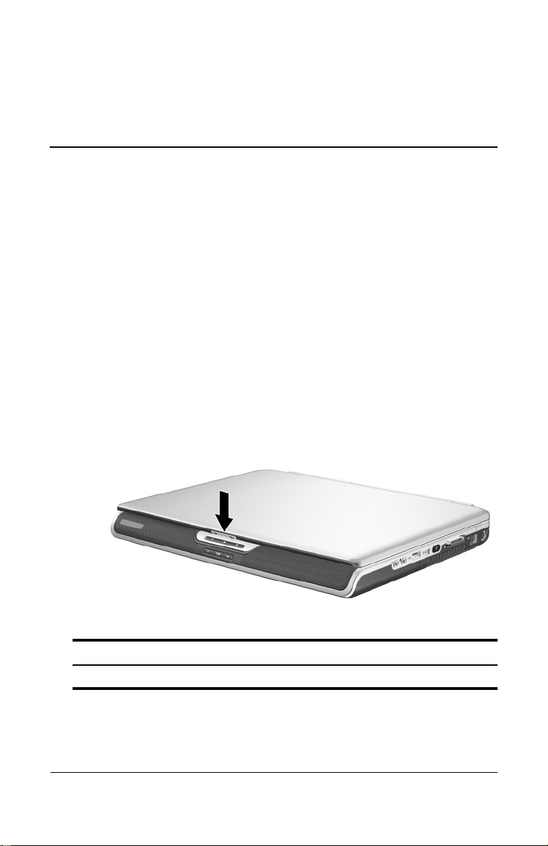
Display
1
Component Description
Display release latch Opens the notebook.
Hardware Guide 1–1
Page 10
Hardware Components
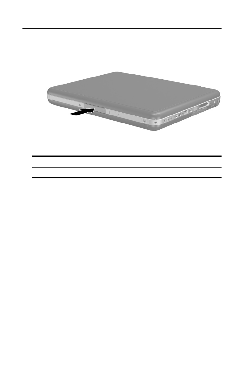
Component Description
Display release latch Opens the notebook.
1–2 Hardware Guide
Page 11
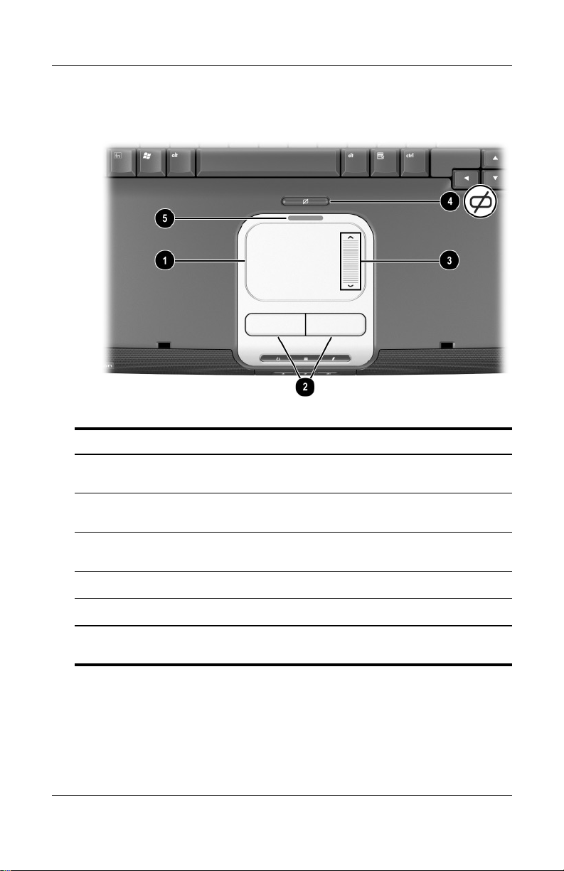
TouchPad
Component Description
TouchPad* Moves the pointer and selects or
1
activates items on the screen.
Hardware Components
Left and right TouchPad
2
buttons
TouchPad scroll pad Functions like the wheel of an external
3
TouchPad on/off button Turns TouchPad on or off.
4
TouchPad light On: TouchPad is enabled.
5
*For information about TouchPad settings, see Chapter 2, “TouchPad and
Keyboard.”
Hardware Guide 1–3
Function like the left and right buttons
of an external mouse.
mouse for scrolling up and down.
Page 12
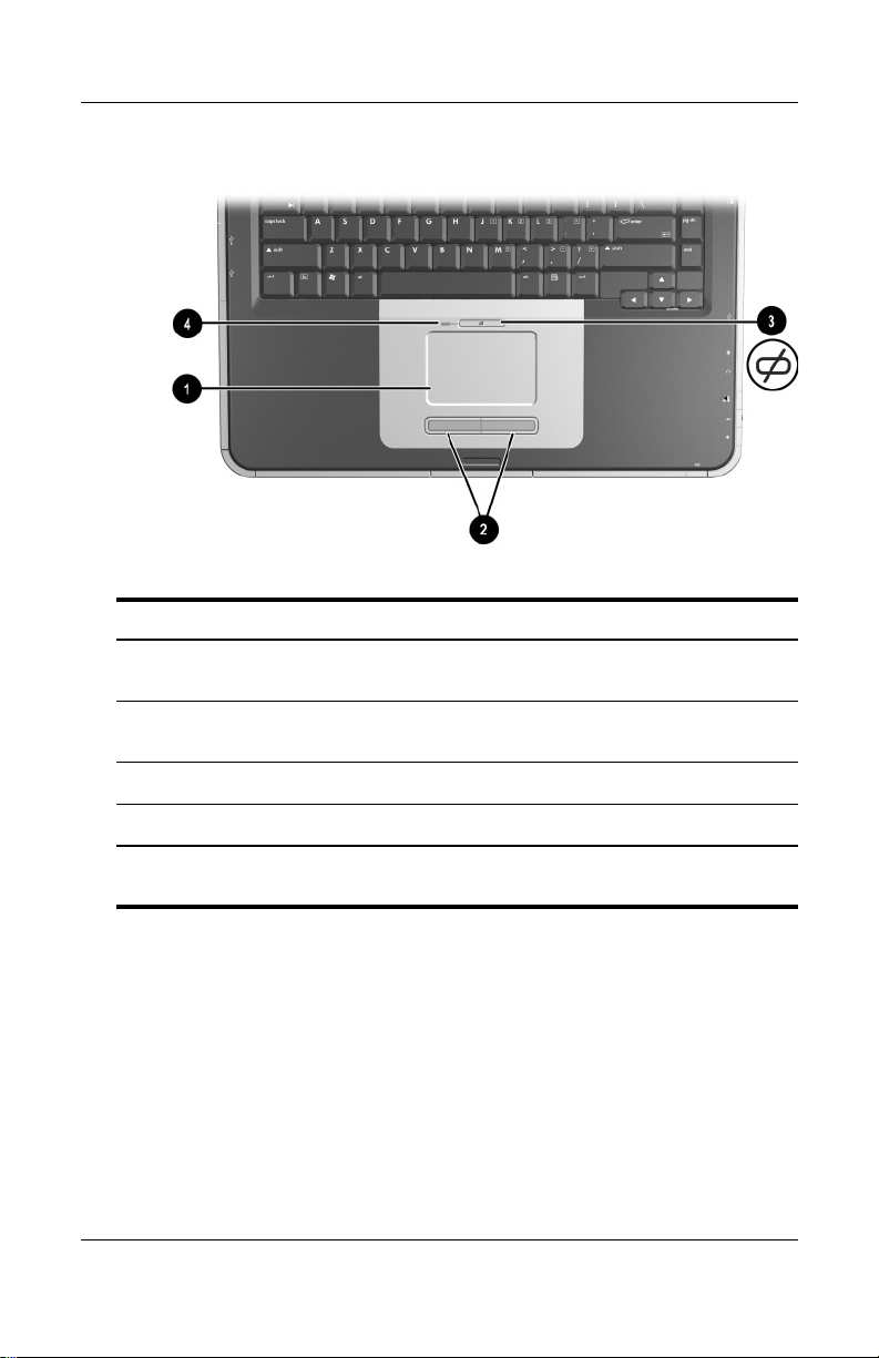
Hardware Components
Component Description
TouchPad* Moves the pointer and selects or
1
Left and right TouchPad
2
buttons
activates items on the screen.
Function like the left and right buttons
on an external mouse.
TouchPad on/off button Turns TouchPad on or off.
3
TouchPad light On: TouchPad is enabled.
4
*For information about TouchPad settings, see Chapter 2, “TouchPad and
Keyboard.”
1–4 Hardware Guide
Page 13
Top Components
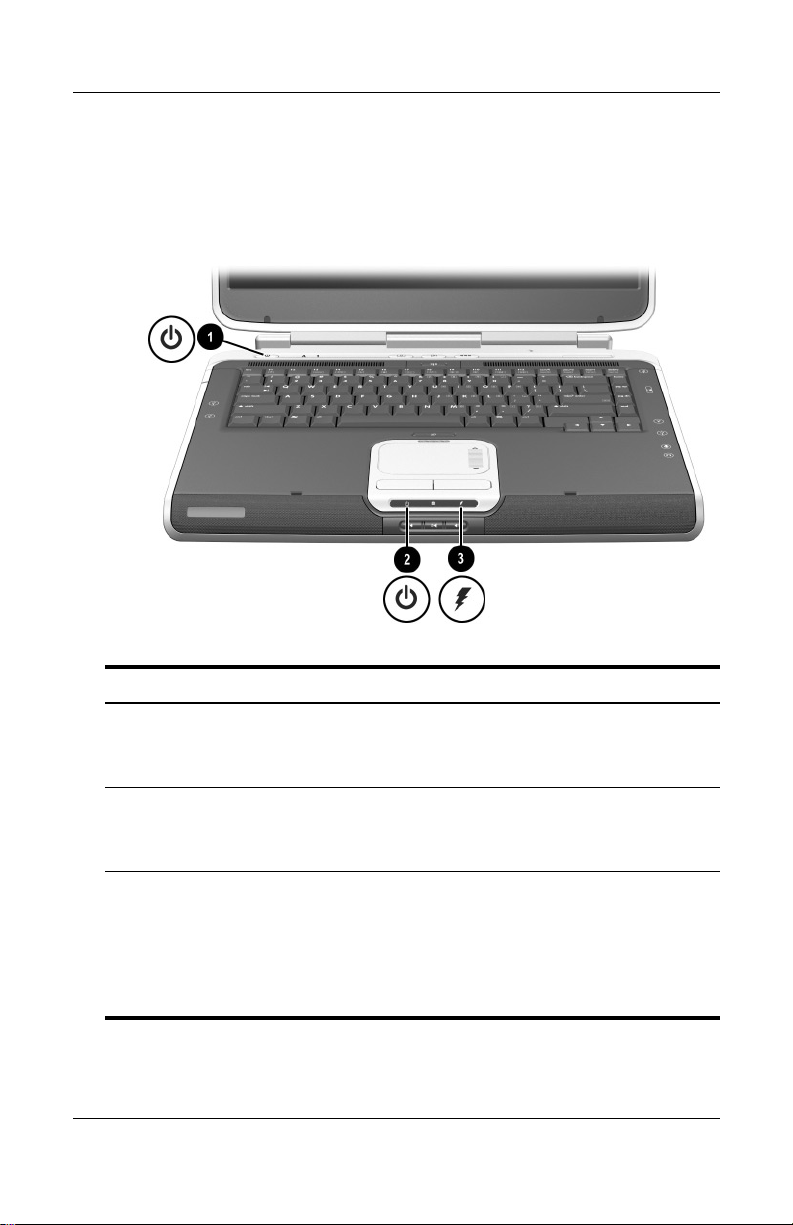
Power Lights
Hardware Components
Component Description
Power button light On: Notebook is turned on.
1
Blinking: Notebook is in Standby.
Off: Notebook is off or in Hibernation.
Power/Standby light On: Notebook is turned on.
2
Blinking: Notebook is in Standby.
Off: Notebook is off or in Hibernation.
Battery light On: Battery pack is charging.
3
Blinking: Battery pack has reached a
low-battery condition.
Off: AC power is applied, with battery
pack either fully charged or not
installed, or no AC power is applied.
Hardware Guide 1–5
Page 14
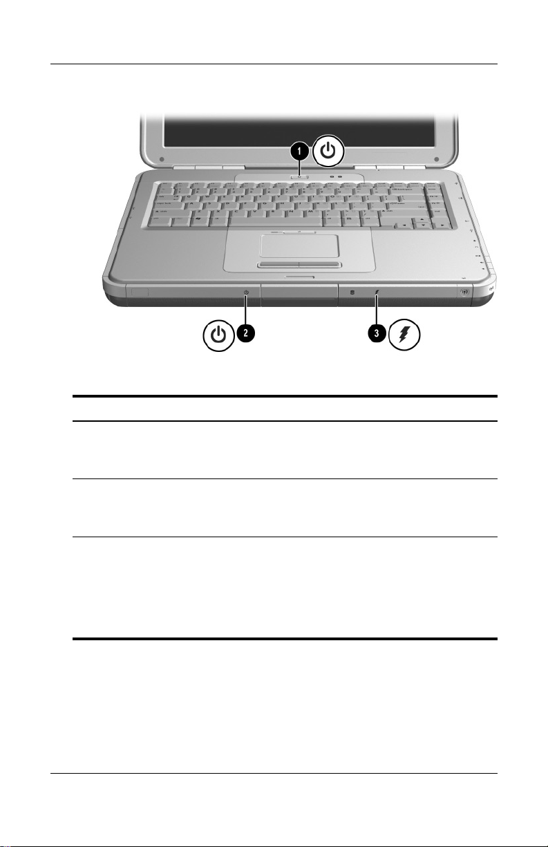
Hardware Components
Component Description
Power button light On: Notebook is turned on.
1
Blinking: Notebook is in Standby.
Off: Notebook is off or in Hibernation.
Power/Standby light On: Notebook is turned on.
2
Blinking: Notebook is in Standby.
Off: Notebook is off or in Hibernation.
Battery light On: Battery pack is charging.
3
Blinking: Battery pack has reached a
low-battery condition.
Off: AC power is applied, with battery
pack either fully charged or not
installed, or no AC power is applied.
1–6 Hardware Guide
Page 15
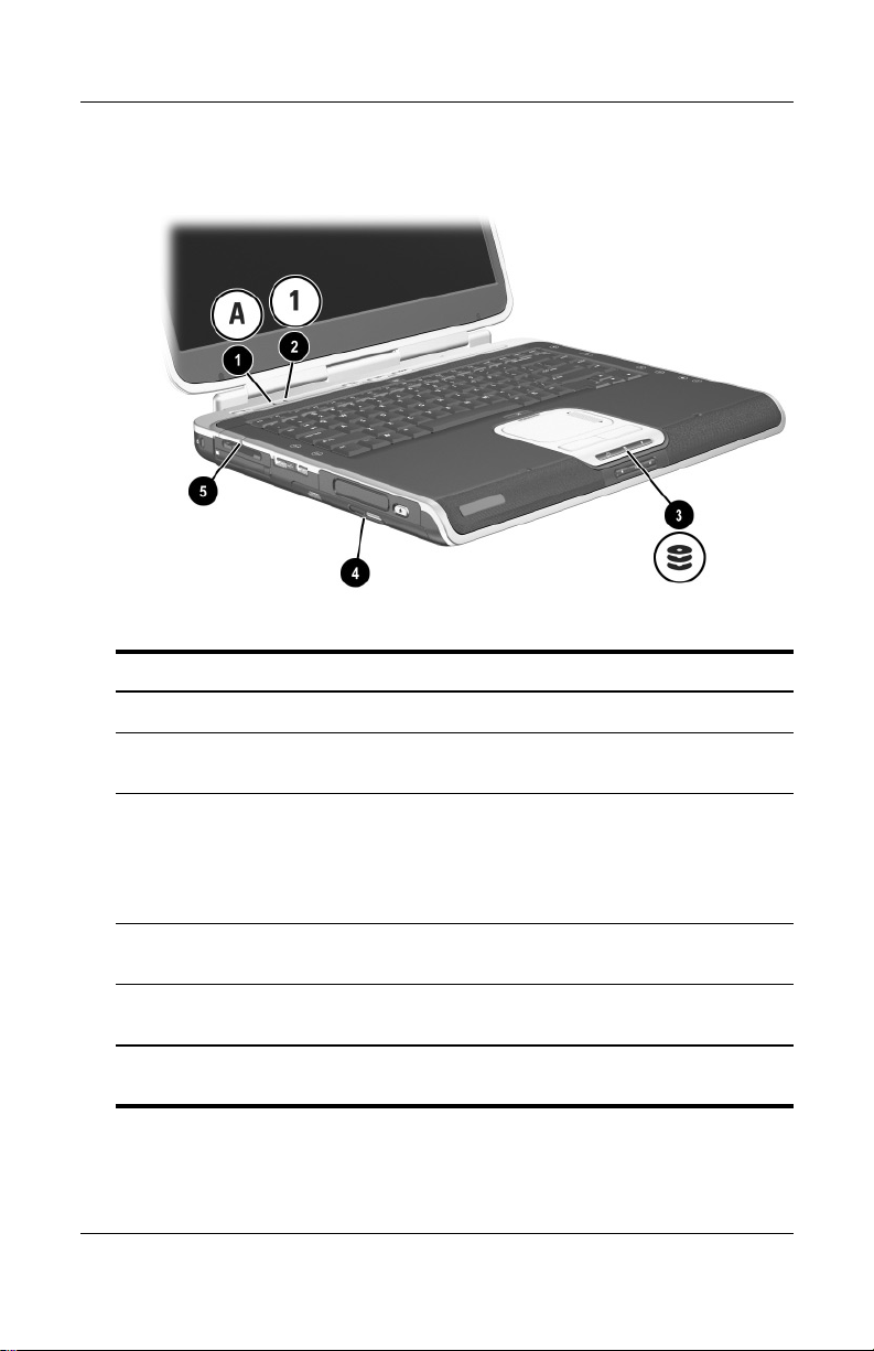
Keyboard and Drive Lights
Component Description
Caps lock light On: Caps lock is on.
1
Hardware Components
Num lock light On: Num lock or the internal
2
IDE (Integrated Drive
3
Electronics) light; also
referred to as hard
drive/optical drive activity
light
Optical disk drive light On: The optical drive bay is being
4
5-in-1 Digital Media slot light
5
(select models).
*For information about using num lock, the internal keypad, or an external
keypad, see Chapter 2, “TouchPad and Keyboard.”
Hardware Guide 1–7
keypad is on.*
On: The internal hard drive or optical
drive bay is being accessed.
accessed.
On: Slot is accessing an optional
digital media card.
Page 16
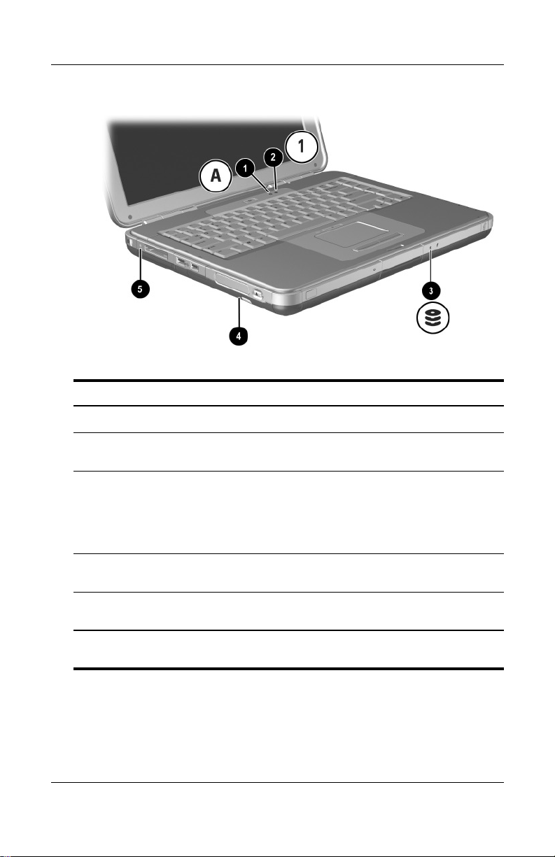
Hardware Components
Component Description
Caps lock light On: Caps lock is on.
1
Num lock light On: Num lock or the internal
2
keypad is on.*
IDE (Integrated Drive
3
Electronics) light; also
referred to as hard
drive/optical drive activity
light
Optical disk drive light On: The optical drive bay is being
4
5-in-1 Digital Media slot light
5
(select models)
*For information about using num lock, the internal keypad, or an external
keypad, see Chapter 2, “TouchPad and Keyboard.”
On: The internal hard drive or the
optical drive bay is being accessed.
accessed.
On: Slot is accessing an optional
digital media card.
1–8 Hardware Guide
Page 17
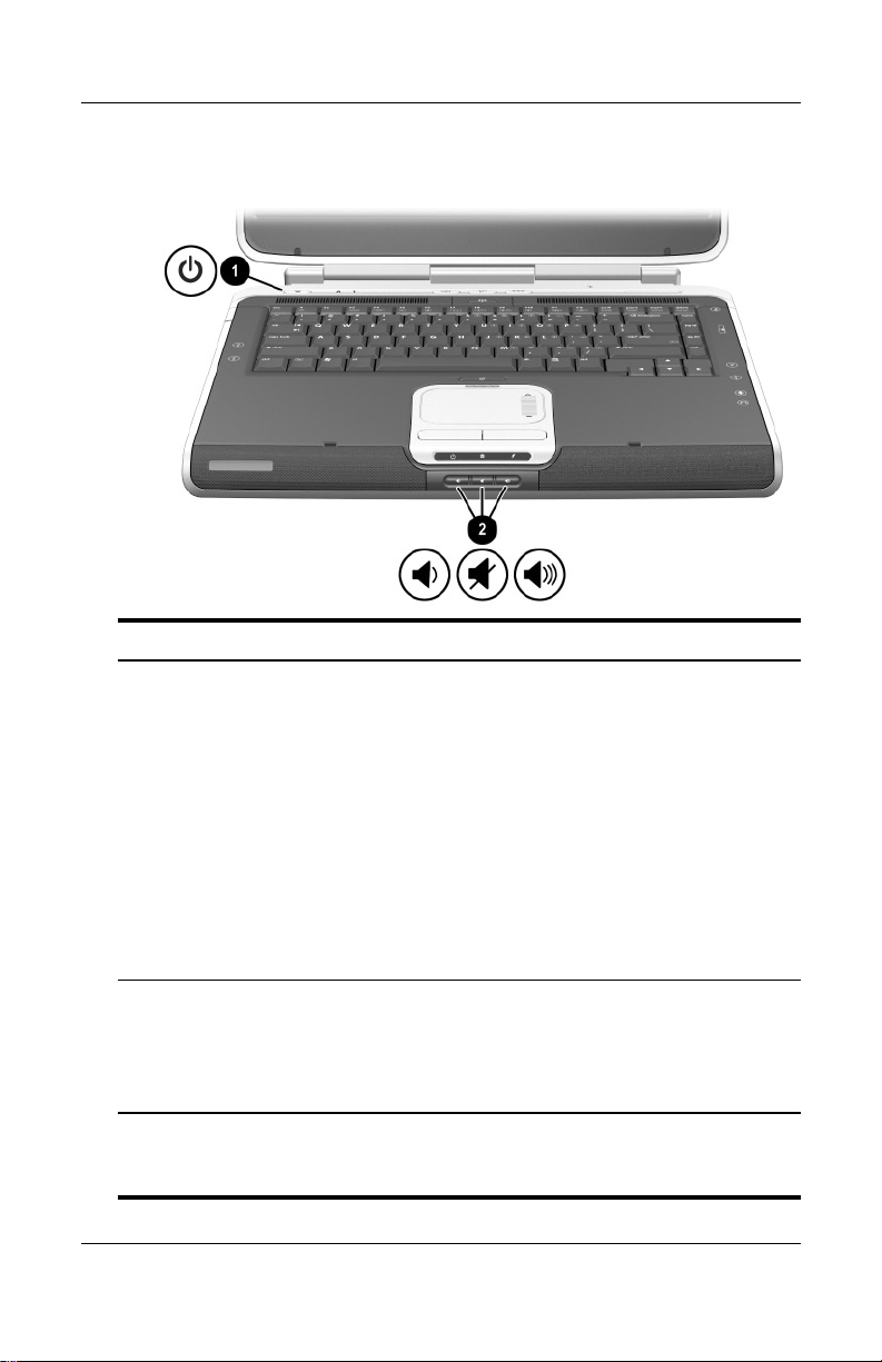
Power and Volume Controls
Component Description
Power button* When the notebook is:
1
■ Off, press the button to turn on the notebook.
■ On, briefly press the button to initiate Hibernation.
■ In Standby, briefly press the button to resume
from Standby.
■ In Hibernation, briefly press the button to resume
from Hibernation.
Hardware Components
If the system has stopped responding
✎
and Windows shutdown procedures cannot
be used, press and hold the button for at least
4 seconds to turn off the notebook.
2
Volu me
buttons (3)
Decrease, mute, and increase the system volume:
■ To decrease volume, use the left button.
■ To mute or restore volume, use the middle button.
■ To increase volume, use the right button.
*This table describes default settings. For information about changing the
function of the power button, refer to the “Power” chapter in the
on this CD.
Guide
Hardware Guide 1–9
Software
Page 18
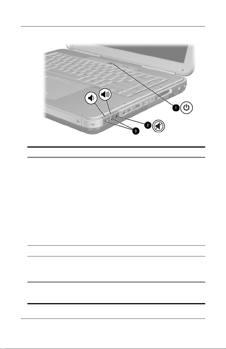
Hardware Components
Component Description
Power button* When the notebook is:
1
■ Off, press the button to turn on the notebook.
■ On, briefly press the button to initiate Hibernation.
■ In Standby, briefly press the button to resume
from Standby.
■ In Hibernation, briefly press the button to resume
from Hibernation.
If the system has stopped responding and
✎
Microsoft
procedures cannot be used, press and hold
the button for at least 4 seconds to turn off
the notebook.
Mute button On: Audio is muted.
2
3
Volu me
buttons (2)
Decrease and increase the system volume:
■ To decrease volume, use the left button.
® Windows® shutdown
■ To increase volume, use the right button.
*This table describes default settings. For information about changing the
function of the power button, refer to the “Power” chapter in the
on this CD.
Guide
1–10 Hardware Guide
Software
Page 19
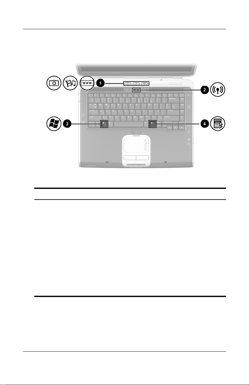
Hardware Components
Quick Launch Buttons and Keyboard Keys
Component Description
Quick Launch buttons:
1
Picture, Media, and Internet
Hardware Guide 1–11
From left to right: 3 programmable
buttons enable you to access the
My Pictures folder, a multimedia
application, and the Internet with
one keystroke.
The icon on each button represents the
default destination. Buttons can be
programmed to point to other locations.
See the instructions on
✎
changing the destination of
Quick Launch buttons in
Chapter 2, “TouchPad and
Keyboard.”
(continued)
Page 20

Hardware Components
Wireless On/Off button Enables wireless functionality, but does
2
Windows logo key Displays Windows Start menu.
3
Windows Applications key Displays shortcut menu for any
4
not create a wireless connection.
To set up and complete a
✎
wireless connection, additional
hardware and software might
be required.
highlighted items.
1–12 Hardware Guide
Page 21
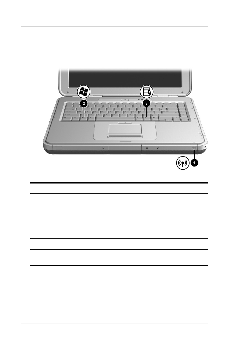
Wireless On/Off Button and Application Keys
Component Description
Hardware Components
Wireless On/Off button Enables wireless functionality, but
1
Windows logo key Displays Windows Start menu.
2
Windows Applications key Displays shortcut menu for any
3
Hardware Guide 1–13
does not create a wireless connection.
To set up and complete a
✎
wireless connection,
additional hardware and
software might be required.
highlighted items.
Page 22
Hardware Components
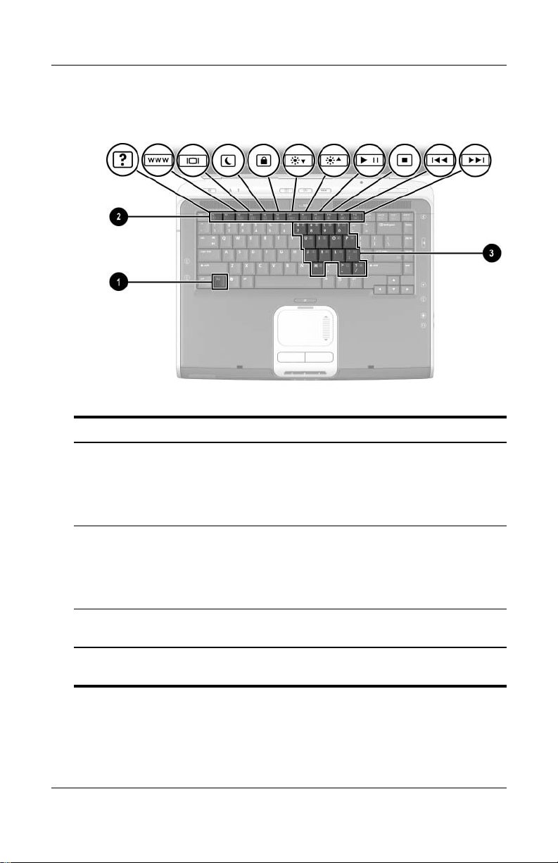
Function and Keypad Keys
Component Description
Fn key Combines with the function keys to
1
perform additional system and
application tasks. For example,
pressing Fn+F8 increases screen
brightness.
Function keys (11)* Perform system and application tasks.
2
When combined with the Fn
function keys F1
additional tasks as hotkeys. (The
F2 function key is not used.)
Keypad keys (15) Can be used like the keys on an
3
*For more information, refer to the “Hotkey Quick Reference” section in
Chapter 2, “TouchPad and Keyboard.”
1–14 Hardware Guide
external numeric keypad.
through F12 perform
key,
Page 23
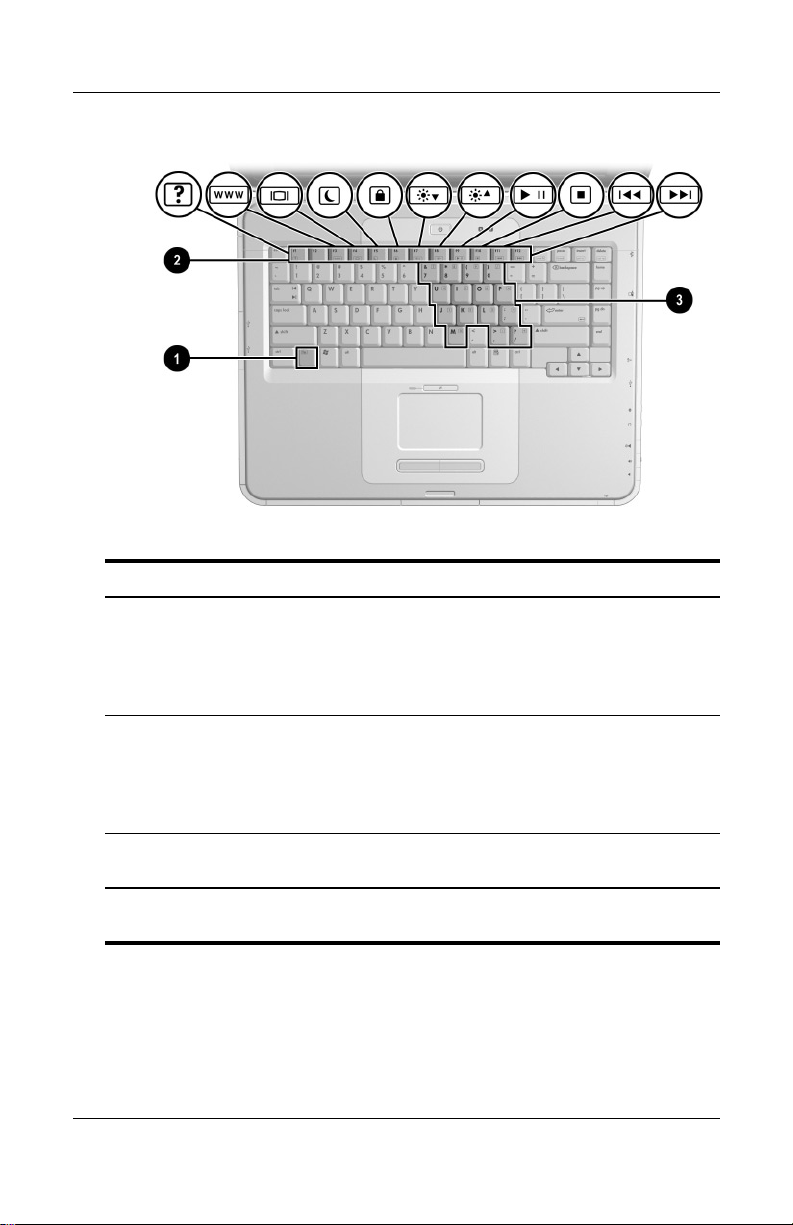
Hardware Components
Component Description
Fn key Combines with the function keys to
1
Function keys (11)* Perform system and application tasks.
2
perform additional system and
application tasks. For example,
pressing Fn+F8 increases screen
brightness.
When combined with the Fn
function keys F1
additional tasks as hotkeys. (The
function key is not used.)
F2
through F12 perform
key,
Keypad keys (15) Can be used like the keys on an
3
*For more information, refer to the “Hotkey Quick Reference” section in
Chapter 2, “TouchPad and Keyboard.”
external numeric keypad.
Hardware Guide 1–15
Page 24
Hardware Components
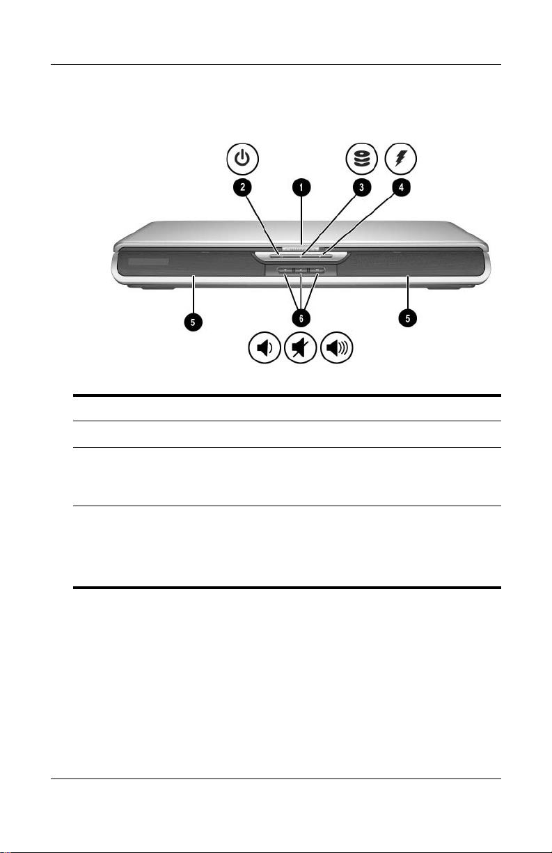
Front Components
Component Description
Display release latch Opens the notebook.
1
Power/Standby light On: Notebook is turned on.
2
Blinking: Notebook is in Standby.
Off: Notebook is off or in Hibernation.
IDE (Integrated Drive
3
Electronics) light; also
referred to as hard
drive/optical drive activity
light
1–16 Hardware Guide
On: The internal hard drive or optical
drive bay is being accessed.
(continued)
Page 25

Hardware Components
Battery light On: Battery pack is charging.
4
Blinking: Battery pack has reached a
low-battery condition.
Off: AC power is applied, with battery
pack either fully charged or not
installed, or no AC power is applied.
Stereo speakers (2) Produce stereo sound.
5
Volume and mute buttons (3) Decrease, mute, and increase the
6
system volume:
■ To decrease volume, use the
left button.
■ To mute or restore volume, use
the middle button.
■ To increase volume, use the
right button.
Hardware Guide 1–17
Page 26
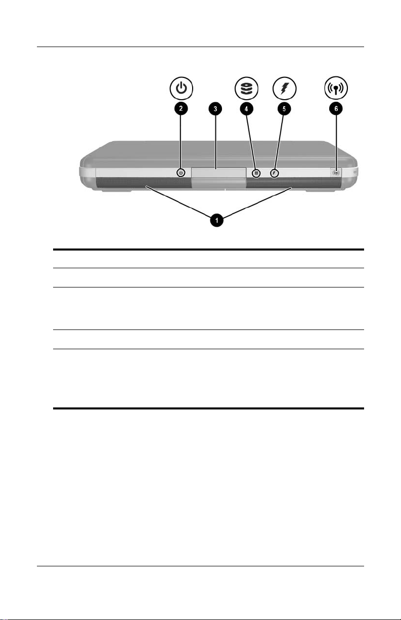
Hardware Components
Component Description
Stereo speakers (2) Produce stereo sound.
1
Power/Standby light On: Notebook is turned on.
2
Blinking: Notebook is in Standby.
Off: Notebook is off or in Hibernation.
Display release latch Opens the notebook.
3
IDE (Integrated Drive
4
Electronics) light; also
referred to as hard
drive/optical drive activity
light
1–18 Hardware Guide
On: The internal hard drive or optical
drive bay is being accessed.
Page 27

Hardware Components
Battery light On: Battery pack is charging.
5
Blinking: Battery pack has reached a
low-battery condition.
Off: AC power is applied, with battery
pack either fully charged or not
installed, or no AC power is applied.
Wireless On/Off button Enables wireless functionality, but
6
does not create a wireless connection.
To set up and complete a
✎
wireless connection, additional
hardware and software might be
required.
Hardware Guide 1–19
Page 28
Hardware Components
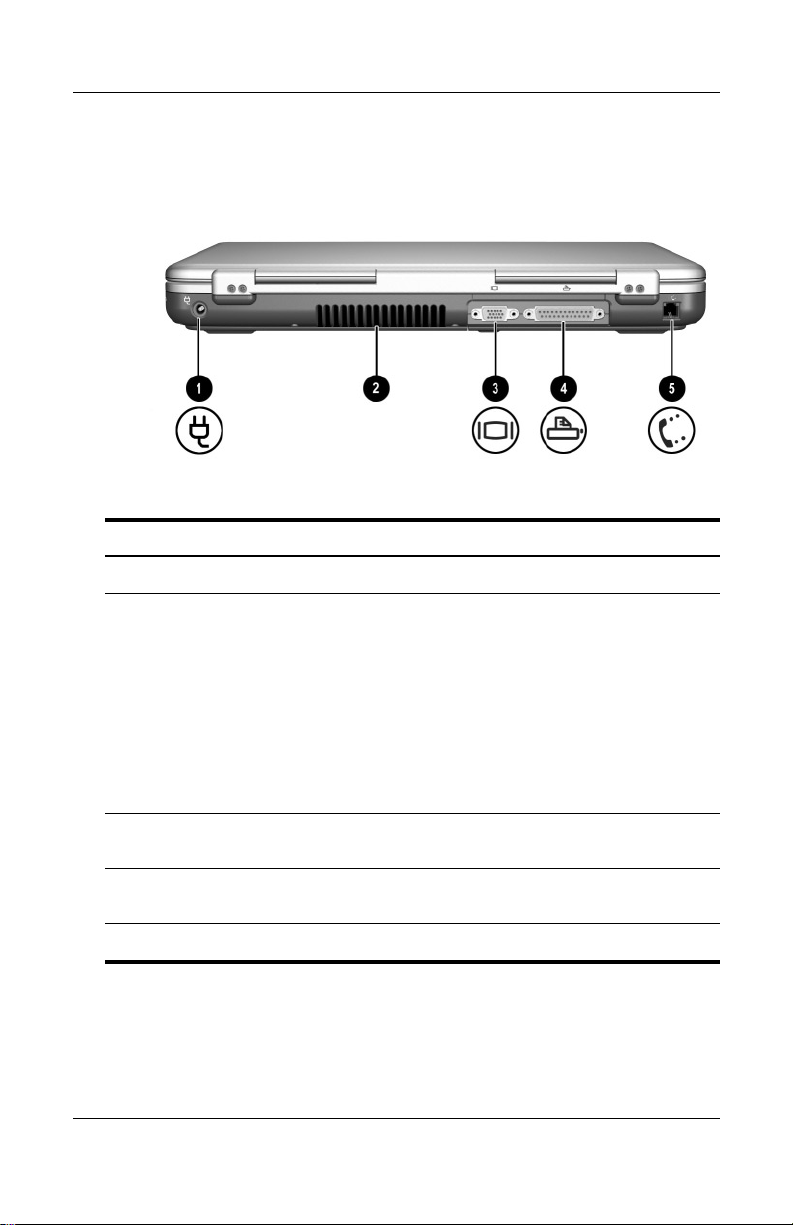
Rear Components
Component Description
Power connector Connects an AC adapter.
1
Exhaust vent Allows airflow to cool internal
2
components. Additional vents are on
the bottom of the notebook.
To prevent overheating, do
Ä
not obstruct the vent. Do not
allow a hard surface, such as
an adjoining printer, or a soft
surface, such as bedding or
clothing, to block airflow.
External monitor connector Connects an optional external monitor
3
Parallel connector Connects an optional parallel device,
4
RJ-11 jack Connects the modem cable.
5
1–20 Hardware Guide
or overhead projector.
such as a printer.
Page 29
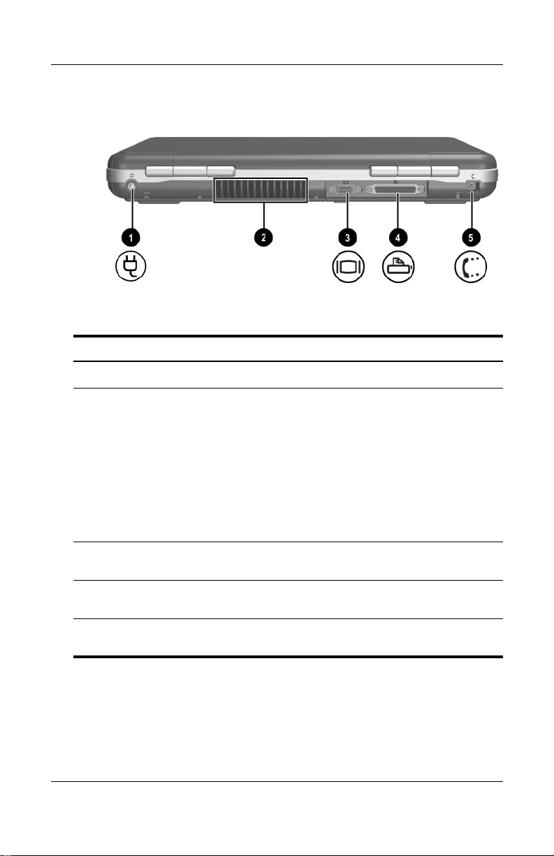
Hardware Components
Component Description
Power connector Connects an AC adapter.
1
Exhaust vent Allows airflow to cool internal
2
External monitor connector Connects an optional external monitor
3
components. Additional vents are
on the bottom of the notebook.
To prevent overheating, do
Ä
not obstruct the vent. Do not
allow a hard surface, such as
an adjoining printer, or a soft
surface, such as bedding or
clothing, to block airflow.
or overhead projector.
Parallel connector Connects an optional parallel device,
4
RJ-11 jack (select models) Connects the modem cable.
5
Hardware Guide 1–21
such as a printer.
(select models)
Page 30
Hardware Components
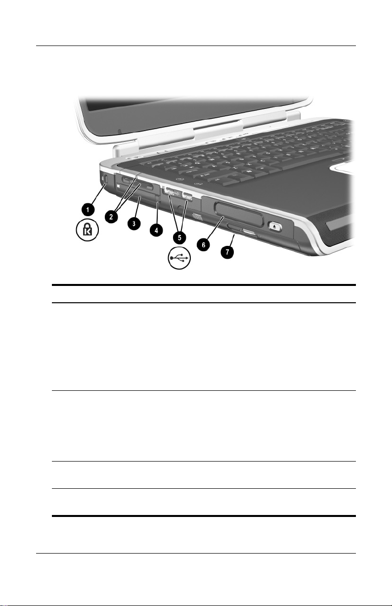
Left-Side Components
1
Component Description
Security cable slot Attaches an optional security cable to
1
the notebook.
The purpose of security
✎
solutions is to act as a
deterrent. These solutions do
not prevent the product from
being mishandled or stolen.
5-in-1 Digital Media slot and
2
light (select models)
PC Card slot Supports an optional Type I or Type II
3
PC Card eject button Ejects an optional PC Card from the
4
1–22 Hardware Guide
Supports 5 optional digital media
formats: SD Memory Card,
MultiMediaCard, SmartMedia, Memory
Stick, and Memory Stick Pro.
Light On: Slot is accessing digital
media.
32-bit (CardBus) or 16-bit PC Card.
PC Card slot.
(continued)
Page 31

Hardware Components
USB connectors (2) Connect optional USB device, such as
5
printers.
Three drive configurations:
6
optional Digital Bay, optional
diskette drive, no drive
One of 4 optical drive bay
7
configurations
Digital Bay: Supports optional
pocket-sized HP USB Digital Drive.
Diskette drive: Supports standard
1.4-MB diskette.
No drive: No drive is installed.
■ CD-ROM drive
■ DVD-ROM drive
■ DVD/CD-RW combo drive—Can
write to recordable CDs, but
cannot write to recordable DVDs.
(Type of drive varies by model.)
■ DVD+RW/R and CD-RW combo
drive—Can write to both
recordable CDs and DVDs.
Hardware Guide 1–23
Page 32

Hardware Components
Component Description
Security cable slot Attaches an optional security cable to
1
the notebook.
✎
PC Card slot (1 or 2 slots,
2
select models)
Supports an optional Type I or Type II
32-bit (CardBus) or 16-bit PC Card.
The purpose of security
solutions is to act as a
deterrent. These solutions do
not prevent the product from
being mishandled or stolen.
PC Card eject button (1 or
3
2 buttons, select models)
1–24 Hardware Guide
Ejects an optional PC Card from the
PC Card slot.
(continued)
Page 33

Hardware Components
USB connectors (2) Connect optional USB devices, such
4
as printers.
Three drive configurations:
5
optional Digital Bay, optional
diskette drive, no drive
One of 4 optical drive bay
6
configurations
Digital Bay: Supports optional
pocket-sized HP USB Digital Drive.
Diskette drive: Supports standard
1.4-MB diskette.
No drive: No drive is installed.
■ CD-ROM drive
■ DVD-ROM drive
■ DVD/CD-RW combo drive—Can
write to recordable CDs, but
cannot write to recordable DVDs.
(Type of drive varies by model.)
■ DVD+RW/R and CD-RW combo
drive—Can write to both
recordable CDs and DVDs.
Hardware Guide 1–25
Page 34

Hardware Components
Right-Side Components
Component Description
Audio-out headphone jack Connects an optional headphone, a
1
headset, or powered stereo speakers.
Also connects the audio function of an
audio/video device, such as a
television or VCR.
Audio-in microphone jack Connects an optional external
2
USB connector Connects an optional USB device,
3
1394 connector
4
(select models)
1–26 Hardware Guide
microphone.
such as a printer.
Connects an optional IEEE1394
device, such as a camcorder.
(continued)
Page 35

Hardware Components
Infrared port
5
(select models)
Expansion port Connects an optional HP Notebook
6
RJ-45 network jack Connects an optional network cable.
7
S-Video-out jack Connects an optional S-Video device,
8
Provides wireless communication
between the notebook and an optional
IrDA-compliant device.
Expansion Base.
such as a television, VCR,
camcorder, overhead projector, or
video capture card.
Hardware Guide 1–27
Page 36

Hardware Components
Component Description
Wireless on/off light On: Wireless functionality is enabled, but
1
wireless connection might not be
configured.
Off: No wireless device is active.
Volume buttons (3) and
2
audio mute light
Decrease, mute, and increase the system
volume:
■ To decrease volume, use left button.
■ To increase volume, use middle
button.
■ To mute or restore volume, use right
button.
■ Light on: Audio is muted.
Audio-out headphone jack Connects an optional headphone, a
3
headset, or powered stereo speakers.
Also connects the audio function of an
audio/video device, such as a television
or VCR.
(continued)
1–28 Hardware Guide
Page 37

Hardware Components
Audio-in microphone jack Connects an optional external
4
USB connector Connects an optional USB device, such
5
1394 connector
6
(select models)
microphone.
as a printer.
Connects an optional IEEE 1394 device,
such as a camcorder.
Infrared port
7
(select models)
Expansion port Connects an optional HP Notebook
8
RJ-45 network jack Connects an optional network cable.
9
S-Video-out jack Connects an optional S-Video device,
-
Provides wireless communication
between the notebook and an optional
IrDA-compliant device.
Expansion Base.
such as a television, VCR, camcorder,
overhead projector, or video capture card.
Hardware Guide 1–29
Page 38

Hardware Components
Bottom Components
Component Description
Battery release latch Releases the battery pack from the
1
battery bay.
Battery bay Holds the battery pack.
2
Exhaust vents Allow airflow to cool internal components.
3
To prevent overheating, do not
Ä
obstruct the vent. Do not allow a
hard surface, such as an
adjoining printer, or a soft
surface, such as bedding or
clothing, to block airflow.
Hard drive bay Holds the primary hard drive.
4
Memory compartment Contains 2 memory slots, one of which is
5
1–30 Hardware Guide
accessible for an optional 128-MB,
256-MB, 512-MB, or 1024-MB memory
module upgrade. As shipped, the memory
slot might be filled with a replaceable
memory module, or it might be vacant,
depending on the notebook model.
Page 39

Hardware Components
Component Description
Battery release latch Releases the battery pack from the
1
Battery bay Holds the battery pack. (Battery shipment
2
battery bay.
and type vary by model.)
Exhaust vents Allow airflow to cool internal components.
3
To prevent overheating, do not
Ä
obstruct the vent. Do not allow a
hard surface, such as an
adjoining printer, or a soft
surface, such as bedding or
clothing, to block airflow.
Hard drive bay Holds the primary hard drive.
4
Memory compartment Contains 2 memory slots, one of which is
5
Hardware Guide 1–31
accessible for an optional 128-MB,
256-MB, 512-MB, or 1024-MB memory
module upgrade. As shipped, the memory
slot might be filled with a replaceable
memory module, or it might be vacant,
depending on the notebook model.
Page 40

Hardware Components
Labels
The labels affixed to the bottom of the notebook and to the inside
of the battery compartment provide information you might need
when troubleshooting system problems or traveling abroad with
the notebook.
■ The Service Tag label affixed to the bottom of the notebook
contains the product name, product number (P/N), and serial
number (S/N). You will need the notebook serial number and
product number if you call customer support.
■ The Microsoft Certificate of Authenticity label affixed to the
bottom of the notebook contains the Product Key. You might
need this number to update or troubleshoot problems with the
operating system.
■ The System label affixed to the inside of the battery
compartment provides regulatory information about the
notebook.
■ The Product identification label affixed to the inside of the
battery compartment contains the serial number (S/N) of
the notebook and a code describing the original configuration
of the notebook.
■ The Modem approval label affixed to an optional internal
modem provides regulatory information.
■ The wireless certification labels affixed to the inside of the
battery compartment are specific to various types of optional
wireless devices. These labels provide regulatory information
and list the countries in which the optional wireless devices
have been approved for use. You might need the wireless
device information in order to use the wireless device while
traveling.
1–32 Hardware Guide
Page 41

Hardware Components
Additional Standard Components
The components included with the notebook vary by geographic
region and by model. The following illustrations and tables
identify the standard external components included with most
notebook models.
Documentation Library CD
Your notebook Documentation Library CD includes the
following guides:
■ Hardware Guide (the document you are viewing)
■ Software Guide
■ Maintenance, Shipping and Travel guide
■ Regulatory and Safety Notices
■ Safety & Comfort Guide
■ Troubleshooting guide
■ Modem and Networking guide
For information about using the Documentation Library CD,
refer to the printed Startup Guide included with the notebook.
Hardware Guide 1–33
Page 42

Hardware Components
Cords, Cables and Adapters
Component Description
Power cord* Connects the AC adapter to an
1
AC adapter** Converts AC power to DC power.
2
AC electrical outlet.
Modem cables
3
(select models)*
Country-specific modem
4
adapter (included by region
as required)
Japan-specific outlet adapter
5
(Japan only)
*Power cords and modem cables vary in appearance by region.
**AC adapters vary by region.
1–34 Hardware Guide
Connects the modem to an
RJ-11 telephone jack or to a
country-specific modem adapter.
Adapts the modem cable to a
non-RJ-11 telephone jack.
Connects the AC adapter to a 2-prong
electrical outlet.
Page 43

TouchPad and Keyboard
Using the TouchPad
The TouchPad duplicates the functions of an optional external
mouse.
2
Hardware Guide 2–1
Page 44

TouchPad and Keyboard
■ To move the pointer, slide your finger across the TouchPad
surface 1 in the direction you want to move the cursor.
If the cursor continues to move after you take your finger
✎
off the TouchPad, wait a few seconds for the cursor to stop
moving.
■ Use the left and right TouchPad buttons 2 as you would the
left and right buttons on an external mouse.
■ Use the TouchPad scroll pad 3 as you would the arrows on
the scroll bars on the edges of windows. This moves the
viewing area up, down, right, and left.
■ Use the TouchPad on/off button 4 to turn off the Touchpad.
This also turns off the TouchPad light 5.
Identifying TouchPad components
2–2 Hardware Guide
Page 45

TouchPad and Keyboard
■ To move the pointer, slide your finger across the TouchPad
surface 1 in the direction you want to move the cursor.
If the cursor continues to move after you take your finger
✎
off the TouchPad, wait a few seconds for the cursor to stop
moving.
■ Use the left and right TouchPad buttons 2 as you would the
left and right buttons on an external mouse.
■ Use the TouchPad on/off button 3 to turn off the Touchpad.
This also turns off the TouchPad light 4.
Identifying TouchPad components
Hardware Guide 2–3
Page 46

TouchPad and Keyboard
Setting TouchPad Preferences
The TouchPad is supported by the mouse software in the
operating system. To access the Mouse Properties window, select
Start > Control Panel > Printers and Other Hardware > Mouse.
Among the settings you can select are:
■ TouchPad tapping, which enables you to tap the TouchPad
once or twice to select an object.
■ Inertial Movement, which enables you to continue to scroll
even though your finger has reached the edge of the
TouchPad.
■ Ty ping, which prevents inadvertent tapping when typing on
the keyboard.
Other features, such as sensitivity, virtual scrolling, mouse trails,
and mouse speed preferences, are available in the Mouse
Properties window.
2–4 Hardware Guide
Page 47

Using the Hotkeys
In this guide, the function keys are capitalized (Fn, F5). The
✎
function keys on your keyboard might be lowercase (fn, f5).
TouchPad and Keyboard
Hotkeys are preset combinations of the
the function keys 2. Excluding function key
F1 through F12 represent the hotkey functions available on your
notebook. The
Identifying hotkeys
F2 function key is not used.
Fn key 1 and one of
F2, the icons on
Hardware Guide 2–5
Page 48

TouchPad and Keyboard
Identifying hotkeys
2–6 Hardware Guide
Page 49

Hotkey Quick Reference
The following table identifies the hotkey functions set at the
factory.
Default Function Hotkey
Open Help and Support Center. Fn+F1
Not used. Fn+F2
Open Microsoft Internet Explorer. Fn+F3
Switch display image. Fn+F4
Initiate Standby. Fn+F5
Initiate QuickLock. Fn+F6
Decrease screen brightness. Fn+F7
Increase screen brightness. Fn+F8
Play, pause, or resume an audio CD or DVD. Fn+F9
Stop an audio CD or DVD. Fn+F10
TouchPad and Keyboard
Play the previous track or chapter of an audio
CD or DVD.
Play the next track of an audio CD or DVD. Fn+F12
Hardware Guide 2–7
Fn+F11
Page 50

TouchPad and Keyboard
Hotkey Procedures
To use a hotkey command on the notebook keyboard:
■ Briefly press the Fn key, and then briefly press the second
key of the command.
-or-
■ Press and hold down the Fn key, briefly press the second key,
and then release both keys simultaneously.
Hotkey Commands
Open Help and Support Center (Fn+F1)
The Help and Support Center provides a comprehensive online
resource tool for contacting an HP support specialist, for
downloading the latest software driver updates and product
information, and for learning more about using and maintaining
your notebook.
Press the
window.
Fn+F1 hotkey to open the Help and Support Center
Open Internet Explorer (Fn+F3)
Press the Fn+F3 hotkey to open Microsoft Internet Explorer.
Switch Display Image (Fn+F4)
The Fn+F4 hotkey switches the image among display devices
connected to the notebook. For example, if an external monitor
is connected to the notebook, pressing
switches the image among the notebook display, the external
monitor display, and a simultaneous display on both the notebook
and the external monitor.
2–8 Hardware Guide
Fn+F4 multiple times
Page 51

Initiate Standby (Fn+F5)
The Fn+F5 hotkey is set by default to initiate Standby.
■ When the notebook is on, press the Fn+F5 hotkey to initiate
Standby. When Standby is initiated, your work is saved in
random access memory (RAM), the screen is cleared, and
power is conserved. While the notebook is in Standby,
the power/Standby light blinks.
■ To exit Standby, briefly press the power button, or tap the
TouchPad, a key on the keyboard, or other pointing device
component.
The function of the
Fn+F5 hotkey, called the “sleep button” in
Windows, can be changed. For example, the
be set to initiate Hibernation instead of Standby. For more
information about Standby, Hibernation, and changing the
function of the
Fn+F5 hotkey, see the “Power” chapter in the
Software Guide on this CD.
Initiate QuickLock (Fn+F6)
The QuickLock operating system security feature disables the
keyboard and displays the logon screen. QuickLock does not
disable the TouchPad.
TouchPad and Keyboard
Fn+F5 hotkey can
Before you can use this feature, you must set a Windows system
password. For instructions, refer to your operating system
documentation.
To initiate QuickLock, press the
Fn+F6 hotkey. To disable
QuickLock, enter your Windows system password.
Hardware Guide 2–9
Page 52

TouchPad and Keyboard
Decrease Screen Brightness (Fn+F7)
Press the Fn+F7 hotkey to decrease the brightness of the notebook
screen. Decreasing brightness conserves power.
Increase Screen Brightness (Fn+F8)
Press the Fn+F8 hotkey to increase the brightness of the
notebook screen.
Play, Pause or Resume an Audio CD or DVD (Fn+F9)
If an audio CD or DVD is inserted into the optical drive, press
Fn+F9 hotkey to play it.
the
If an audio CD or DVD is playing in the optical drive, press the
Fn+F9 hotkey to pause it.
If you have paused an audio CD or DVD in the optical drive
by pressing the
Fn+F9 hotkey, press the Fn+F9 hotkey again to
resume play.
Stop an Audio CD or DVD (Fn+F10)
If an audio CD or DVD is playing in the optical drive, press
Fn+F10 hotkey to stop it.
the
Play Previous Track of an Audio CD or DVD (Fn+F11)
Press the Fn+F11 hotkey to select the previously played track of
an audio CD or DVD that is playing in the optical drive.
Play Next Track of an Audio CD or DVD (Fn+F12)
Press the Fn+F12 hotkey to play the next track of an audio CD or
DVD playing in the optical drive.
2–10 Hardware Guide
Page 53

Using Quick Launch Buttons
The 3 Quick Launch buttons enable you to use a single keystroke
to access default software applications or the Internet.
TouchPad and Keyboard
Identifying the Quick Launch buttons
Button Name Default Assignment
Picture Opens My Pictures folder and then
1
Media Launches the default multimedia
2
Internet Opens to Microsoft Internet Explorer or
3
Hardware Guide 2–11
launches the default photo and
imaging software application.
software application.
to a personal Web page you can
customize.
Page 54

TouchPad and Keyboard
Reprogramming the Quick Launch Buttons
Your notebook Quick Launch buttons can be assigned to an
Internet location, a network destination, a software application,
or a data file. For example, a Quick Launch button can be
assigned to open your Internet browser to a favorite Web page
or to open an application, such as Microsoft Word, or even a
document, such as an Excel worksheet.
Button assignments can be grouped into schemes. When you
select a scheme, only the button assignments within that scheme
are active. Button assignments and schemes are set up, changed,
or deleted in the Quick Launch buttons window.
To reprogram a button:
1. Select Start > All Programs > Utilities > Quick Launch.
2. On the Quick Launch tab, select the button you want to
reprogram.
3. Type a label for the button, and then select the application,
document, folder, or Web site you want the button to open.
If you want an icon for the button to appear on the taskbar or on
the desktop, select that option on the Onscreen Display tab.
2–12 Hardware Guide
Page 55

Keypad
The notebook has an internal numeric keypad and supports an
optional external numeric keypad or an optional external
keyboard that includes a numeric keypad.
Using the Keypad
The keypad consists of 15 keys that can be used like the keys on
an external keypad.
When the keypad is turned on, each key on the keypad
performs the functions indicated by the icon in the top-right
corner of the key.
The standard functions of the keypad keys are still available while
the keypad is turned on. See “Turning the Keypad On and Off”
later in this chapter.
TouchPad and Keyboard
Identifying the keypad keys
Hardware Guide 2–13
Page 56

TouchPad and Keyboard
Identifying the keypad keys
2–14 Hardware Guide
Page 57

Turning the Keypad On and Off
When the keypad is off, press Fn+num lk 1 on the notebook to
turn the keypad on. When the keypad is on, press
notebook (or the
the keypad off.
The num lock light 2 turns on:
■ When the keypad is on
-or-
■ When an optional external keypad with num lock turned on is
connected to the system.
The keypad cannot be turned on while an optional external
✎
keypad is connected to the USB connector on an optional
HP Notebook Expansion Base.
num lock key on an external keypad) to turn
TouchPad and Keyboard
Fn+num lk on the
Identifying the Fn and
Hardware Guide 2–15
num lock
keys and the num lock light
Page 58

TouchPad and Keyboard
Identifying the Fn and
2–16 Hardware Guide
num lock
keys and the num lock light
Page 59

TouchPad and Keyboard
Switching Key Functions on the Keypad
You can temporarily switch the functions of keys on the keypad
between the standard function and the keypad function by using
the
Fn key or the Fn+shift key combination.
■ To make a standard key function as a keypad key (when the
keypad is turned off), press and hold the
Fn key while
pressing the keypad key.
■ To make a keypad key function as a standard key (while
the keypad is turned on):
❏ Press and hold the Fn key to type in lowercase.
❏ Press and hold Fn+shift to type in uppercase.
When the
Fn key is released, the keys return to their
original mode.
Turning Num Lock Mode On or Off as You Work
To turn num lock on or off on an external keypad as you work,
press the
notebook keypad).
num lock key on the external keypad (not on the
Hardware Guide 2–17
Page 60

Battery Packs
Running the Notebook on Battery Power
The notebook switches between AC power and battery power
according to the availability of an external AC power source,
always preferring AC power. If the notebook contains a charged
battery pack and is running on external AC power, the notebook
will switch to battery power only if the AC adapter is
disconnected from the notebook.
Keeping a battery pack in the notebook enables the battery pack
to charge whenever the notebook is connected to external power
and also protects your work in case of a power outage.
On the other hand, a battery pack in the notebook slowly
discharges even when the notebook is powered off. Whether to
leave a battery pack in the notebook or in storage depends on how
you work.
3
Hardware Guide 3–1
Page 61

Battery Packs
Inserting or Removing the Battery Pack
CAUTION: When removing a battery pack that is the only power
Ä
source, initiate Hibernation or turn off the notebook to prevent loss
of work.
To insert or remove a battery pack:
■ Turn off the notebook or initiate Hibernation by briefly
pressing the power button.
■ To insert a battery pack, slide the battery into the battery bay
until it is seated 1.
■ To remove a battery pack, slide and hold the battery release
latch 2 toward the rear of the notebook as you pull the
battery pack from the battery bay 3.
CAUTION: Do not restore power until the power/Standby light turns
Ä
off, indicating that the notebook is in Hibernation.
■ Turn on the notebook or resume from Hibernation by briefly
pressing the power button.
Inserting or removing the battery pack
3–2 Hardware Guide
Page 62

Inserting or removing the battery pack
Battery Packs
Hardware Guide 3–3
Page 63

Battery Packs
Charging a Battery Pack
The battery pack automatically charges when the notebook is
connected to external power through an AC adapter. The
battery pack charges whether the notebook is powered off or in
use, but it charges faster when the notebook is powered off. When
the notebook is in use, charging will take longer, depending on
system activity.
The battery light on the notebook stays on while the battery pack
is charging. The light turns off when the battery is fully charged.
Identifying the battery light
Identifying the battery light
3–4 Hardware Guide
Page 64

Battery Packs
Obtaining Accurate Charge Information
Charging the battery pack prolongs battery life and increases the
accuracy of the battery gauge. When charging the battery:
■ Allow the battery pack to fully discharge before charging it.
■ Charge the battery pack fully. Even a new battery pack can
display charge information inaccurately if it has not been
charged fully.
■ Fully charging and discharging the battery pack will reduce
the need for battery calibration.
■ A battery pack in a notebook that has been idle for over
one month might need calibrating. See “Calibrating a Battery
Pack” in this chapter for details.
Accessing the Battery Charge Display
To see the amount of charge remaining in the battery pack:
» Select Start > Control Panel > Performance and
Maintenance > Power Options > Power Meter.
If the Power Meter icon is placed on the taskbar, it will change
✎
shape according to whether a battery pack or AC power is the
primary power source.
Interpreting Battery Charge Displays
Most battery charge displays report battery status in terms of
percent of charge remaining and run time remaining.
The run time remaining indicates the approximate running time
left if the battery pack continues to provide power at the current
level. For example, battery run time will decrease if you start
playing a DVD and will increase if you stop playing a DVD.
Hardware Guide 3–5
Page 65

Battery Packs
Placing the Power Meter Icon on the Taskbar
To place the Power Meter icon on the taskbar, access the Power
Options window.
» Select the Advanced tab, and then select the Always show
icon on the taskbar check box.
If the Power Meter icon is on the taskbar, it will change shape
✎
depending on whether a battery pack or AC power is the primary
power source.
Managing Low-Battery Conditions
It is important to respond to a low-battery or critical low-battery
condition. This section describes default battery settings and
ways to protect your work in a low-battery condition.
Identifying a Low-Battery Condition
When the battery pack is the only power source for the notebook
and drops to 5 percent of a full charge, the notebook has reached a
low-battery condition. When this condition occurs, the battery
light blinks and a text warning message is displayed.
The Power Options utility allows you to redefine a low-battery
condition, set audio warnings, and change other power defaults.
For details, see the “Power” chapter in the Software Guide on the
Documentation Library CD.
Identifying a Critical Low-Battery Condition
If you do not resolve a low-battery condition, the notebook enters
a critical low-battery condition. By default, the notebook defines
a critical low-battery condition as 3 percent of a full battery
charge remaining.
3–6 Hardware Guide
Page 66

Battery Packs
The battery light continues to blink and:
■ If Hibernation is enabled (the default setting) and the
notebook is on or in Standby, the system initiates Hibernation
and saves system memory to the hard drive. Unsaved work
might be lost.
■ If Hibernation is disabled and the notebook is on or in
Standby, the notebook remains briefly in Standby, then
shuts down. The power/Standby light turns off, and the
notebook cannot save system memory to the hard drive.
Verifying Hibernation Settings
Hibernation, enabled by default, is an important safeguard in
low-battery situations. To verify that Hibernation is enabled,
access the Power Meter icon, or:
» Select Start > Control Panel > Performance and
Maintenance > Power Options > Hibernate. Make sure that
the Enable Hibernate support check box is selected.
Resolving Low-Battery Conditions
CAUTION: If the notebook has reached a critical low-battery condition
Ä
and initiated Hibernation, do not restore power until the power/Standby
light turns off, indicating that the notebook is in Hibernation.
■ If external power is available to the notebook, connect the
AC adapter.
■ If a charged battery pack is available, shut down the notebook
or initiate Hibernation. Then insert a charged battery pack,
and turn the notebook back on.
■ If no power source is available, save your work. Then initiate
Hibernation or shut down the notebook.
If you cannot resume from Hibernation when power is restored to
the system, you will be prompted to delete the restoration data
and proceed with system boot. Unsaved data will be lost.
Hardware Guide 3–7
Page 67

Battery Packs
Calibrating a Battery Pack
When to Calibrate
Even if a battery pack is heavily used, it should not be necessary
to calibrate it more than once a month. It is not necessary to
calibrate a new battery pack before first use. However, make sure
that the battery pack is fully charged, especially if it is the only
power source.
Calibrate the battery pack under the following conditions:
■ When the battery status display seems inaccurate.
■ When you observe a significant change in normal battery
run time.
■ When the battery pack has not been used for one month
or more.
How to Calibrate
To calibrate a battery pack, you must fully charge, fully
discharge, and then fully recharge the battery pack.
Charging the Battery Pack
Fully charge the battery pack when the notebook is in use. To
charge the battery pack:
1. Insert the battery pack into the notebook.
2. Connect the notebook to external power through an
AC adapter. (The battery light turns on.)
The battery light turns off when the battery pack is fully charged.
3–8 Hardware Guide
Page 68

Discharging the Battery Pack
Disabling Hibernation
To fully discharge the battery pack, disable Hibernation
temporarily.
To disable Hibernation:
» Select the Power Meter icon on the taskbar or access Power
Options > Hibernate, and clear the Enable Hibernate support
check box.
Discharging the Battery Pack
CAUTION: If you plan to leave the notebook unattended during
Ä
discharge, save your work before starting the discharge procedure.
After the battery light turns off, which indicates that the battery
pack is fully charged, begin discharging the battery pack.
To fully discharge the battery pack:
1. Select the Power Meter icon on the taskbar, or select Start >
Control Panel > Performance and Maintenance > Power
Options > Power Schemes.
Battery Packs
2. Write down the 3 settings in the Plugged In column and the
3 settings in the Running on Batteries column, so you can
reset them after calibration.
3. Select the drop-down lists and set all 6 options in both
columns to Never.
4. Select the OK button.
5. Disconnect the notebook from the external power source, but
do not turn off the notebook.
6. Run the notebook on battery power until the battery pack is
fully discharged. The battery light begins to blink when the
battery pack has discharged to a low-battery condition. When
the battery pack is fully discharged, the power/Standby light
turns off and the notebook shuts down.
Hardware Guide 3–9
Page 69

Battery Packs
Recharging the Battery Pack
1. Connect the notebook to external power and keep the
notebook connected until the battery pack is fully recharged
and the battery light turns off.
You can use the notebook while the battery pack is recharging, but
✎
the battery pack will charge faster if the notebook is turned off.
2. Select the Power Meter icon on the taskbar or select Start >
Control Panel > Performance and Maintenance > Power
Options > Power Schemes.
3. Reenter the 3 settings you wrote down for the 3 options in the
Plugged In column and for the 3 options in the Running on
Batteries column.
4. Select the OK button.
CAUTION: To reenable Hibernation after calibrating the battery pack,
Ä
select Start > Control Panel > Performance and Maintenance > Power
Options > Hibernate, and then select the Enable Hibernation check box.
Battery Conservation Procedures and Settings
Using the battery conservation procedures and settings described
in the following section extends the run time of the battery pack.
Conserving Power as You Work
To conserve power while you use the notebook:
■ Plug in the AC adapter, especially if you are using a
CD-ROM or DVD-ROM drive, or any external connections.
■ Turn off wireless and local area network (LAN) connections
and exit modem applications when you are not using them.
■ Set the automatic timeout settings to emphasize saving
power.
3–10 Hardware Guide
Page 70

Battery Packs
■ Unplug external devices not connected to external power
when you are not using them.
■ Stop or remove a PC Card or a digital media card that you are
not using.
■ Decreasing screen brightness by pressing Fn+F7 saves power.
See “Hotkey Commands” in the “TouchPad and Keyboard”
chapter for more about using
Use optional powered speakers instead of the internal
■
speakers, or use the volume buttons to quickly increase and
decrease system volume as you need it.
■ Turn off a device connected to the S-Video connector.
■ If you leave your work, initiate Standby or Hibernation or
shut down the notebook.
■ Select a short wait time, 5 minutes or less, for the display
timeout. To change display timeout settings, select Start >
Control Panel > Performance and Maintenance > Power
Options > Power Meter. Select a short wait time from the
Turn Off Monitor drop-down list, and then select OK.
For more details about using power options, refer to the “Power”
chapter in the Software Guide on the this CD.
Fn+F7.
Storing a Battery Pack
CAUTION: To prevent damage to the battery pack, do not expose it to
Ä
high temperatures for extended periods of time.
If the notebook will be unused and unplugged for more than
2 weeks, remove and store the battery pack.
High temperatures accelerate the self-discharge rate of a stored
battery pack, so place it in a location that is cool and dry.
Before using a battery pack that has been stored for one month or
more, calibrate it. This insures that the battery information
displayed by your notebook is accurate.
Hardware Guide 3–11
Page 71

Battery Packs
Disposing of a Used Battery Pack
WARNING: There is a risk of fire and chemical burn if a battery pack
Å
is handled improperly. Do not disassemble, crush, or puncture a battery
pack or short the contacts on it. Do not expose a battery pack to
temperatures higher than 60°C (140°F), or dispose of it in water or fire.
When a battery pack has reached the end of its useful life, do not
dispose of it in general household waste.
■ In Europe, dispose of or recycle battery packs by using the
public collection system or by returning them to HP, your
authorized HP, or their agents.
■ In other regions, refer to the Worldwide Telephone Numbers
booklet included with the notebook to contact a reseller or
service provider and request information about battery pack
disposal.
For more information about battery pack precautions and disposal
and the complete text of governmental agency notices, refer to the
Regulatory and Safety Notices guide on this CD.
Finding More Power Information
For more information about conserving power, setting power
preferences, and using Standby and Hibernation, refer to the
“Power” chapter in the Software Guide on this CD.
3–12 Hardware Guide
Page 72

About Drive Terms
Hard drives are for permanent storage of data files and software,
such as system files, applications, and drivers. A hard drive is
sometimes called a hard disk drive.
Optional disk drives (select models) include diskette drives. A
diskette drive is sometimes called a floppy disk drive or floppy
drive. Drives are often used to store or transport data.
Optical drives include CD and DVD drives. Optical drives are
used to store or transport data and to play music and movies.
DVD drives have a higher storage capacity than CD drives.
A DVD+RW/R and CD-RW combo drive can write to both
✎
recordable CDs and recordable DVDs.
4
Drives
A DVD/CD-RW combo drive can write to recordable CDs (CD-R
✎
and CD-RW media) but cannot write to recordable DVDs
(DVD+R, DVD+RW, DVD-R, or DVD-RW media).
Hardware Guide 4–1
Page 73

Drives
Depending on your model, the notebook can read or write to
optical drives as described in the following table.
Optical Drive Read Write
CD-ROM Yes No
DVD -RO M Yes No
DVD/CD-RW combo Yes Yes, but only CD media
DVD+RW/R and CD-RW
combo
Ye s Ye s
Optional HP USB Digital Drives (select models) are
pocket-sized, SD (Secure Digital) Memory Card drives for
storing and transferring files such as digital pictures, music,
video, or large data files. An HP USB Digital Drive can be
connected to an optional Digital Bay or to a USB port with the
HP USB Digital Drive cable either retracted or extended.
A diskette, disk, or disc that can be inserted or removed from a
drive is referred to as a drive medium. In this guide, a diskette
is used in a diskette drive, a disk is used in a high-capacity
disk drive, and a disc is used in an optical drive, such as a
CD-ROM drive or DVD-ROM drive. Drive media include
diskettes, CDs, and DVDs.
4–2 Hardware Guide
Page 74

Caring for Drives and Drive Media
Drives and drive media are fragile notebook components that
must be handled with care. The following cautions apply to all
drives. Cautions that concern specific procedures are included
with the procedures.
Caring for Drives
CAUTION: To prevent damage to the notebook or a drive and loss
Ä
of work:
■ Do not remove the internal hard drive except for repair or
replacement.
■ Do not try to remove a Digital Drive while it is still in use.
■ Electrostatic discharge can damage electronic components. To
prevent electrostatic damage to the notebook or a drive, follow
these 2 precautions: (1) Before handling a drive, discharge yourself
from static electricity by touching a grounded metal object, and
(2) Avoid touching the connectors on a drive. For more information
about preventing electrostatic damage, refer to the “Electrostatic
Discharge” section in the
Documentation Library
the
■ Excessive force can damage drive connectors. When you insert a
drive, use only enough force to seat the drive.
■ Handle a drive carefully. Do not drop it.
■ Avoid exposing a hard drive or a diskette to devices with magnetic
fields. Products with magnetic fields include video and audio tape
erasure products, monitors, and speakers. Security devices with
magnetic fields include airport walk-through devices and security
wands. The airport security devices that check carry-on luggage,
usually while it is placed on a conveyor belt, use x-rays instead of
magnetism and will not damage a hard drive or a diskette.
■ Do not spray a drive with cleaners.
■ Avoid exposing a drive to liquids or temperature extremes.
■ If you mail a drive, ship it in packaging that protects it from shock,
vibration, extreme temperatures, and high humidity. Label the
package “FRAGILE.”
Regulatory and Safety Notices
CD.
guide on
Drives
Hardware Guide 4–3
Page 75

Drives
Caring for Drive Media
CAUTION: To prevent damage to drive media:
Ä
■ Do not open the metal shutter of a diskette or touch the disk within
the diskette case.
■ Do not expose a diskette to a strong magnetic field, such as the
security field used by a walk-through security device or a handheld
security wand.
■ Clean a CD or DVD only with a disc cleaning kit, available from
most electronics retailers.
Using Drive Media
Avoiding Standby and Hibernation
CAUTION: Initiating Standby or Hibernation while playing optical
Ä
drive media might stop the play or diminish the quality of the play.
Turn off all media before initiating Standby or Hibernation. If
Standby or Hibernation is accidentally initiated when an optical
drive is in use, you might see a warning message: “Putting the
computer into Hibernation or Standby might stop the playback.
Do you want to continue?” Select No.
Resume from Hibernation or Standby by pressing the power
button briefly. Audio and video might resume or you might need
to restart the drive media.
For details about Standby and Hibernation, refer to the “Power”
chapter in the Software Guide on this CD.
4–4 Hardware Guide
Page 76

Displaying Media Contents
AutoPlay, sometimes called Autorun, is a feature of the operating
system. AutoPlay displays the contents of your media on the
screen when you insert a CD or DVD into an optical drive and
close the tray.
AutoPlay is enabled by default, but can be disabled.
Setting AutoPlay Preferences
AutoPlay is enabled or disabled through the operating system:
1. Select Start > My Computer.
2. Right-click the optical drive.
3. Select Properties > AutoPlay, and follow the instructions on
the screen.
Canceling AutoPlay on an Audio CD
To prevent an audio CD from opening when AutoPlay is enabled,
press the
shift key as you insert the CD.
Drives
Displaying the Contents of a CD or DVD
If AutoPlay is disabled and the contents of a CD or DVD are not
displayed when you insert it, you can display the contents
manually:
1. Select Start > Run, and then type:
X:
(where X = the drive containing the CD or DVD)
2. Press enter.
A drive designation is a letter of the alphabet that the notebook
✎
uses to identify a drive. To display the drive designation of every
drive in the system, select Start > My Computer.
Hardware Guide 4–5
Page 77

Drives
Adding a Drive to the System
The internal hard drive and optical drive are standard features of
the notebook. The type of optical drive varies by notebook model.
Hard drive capacity can also be added with a microdrive PC Card
or an external hard drive.
Some notebook models include an optional diskette drive or
an optional HP USB Digital Drive. The HP USB Digital Drive
can be connected to one of the USB connectors or to the optional
Digital Bay.
An optional disk drive can also be added to the system by
attaching it to one of the USB connectors or to the
1394 connector.
For more on connecting external devices, see Chapter 6,
“External Device Connections.” For details about PC Cards,
see Chapter 8, “Hardware Upgrades.”
4–6 Hardware Guide
Page 78

Using the IDE Drive Light
The IDE (Integrated Drive Electronics) light turns on when the
internal hard drive or an optical drive is being accessed. The light
is also referred to as the hard drive/optical drive activity light.
Identifying the IDE drive light
Drives
Identifying the IDE drive light
Hardware Guide 4–7
Page 79

Drives
Inserting and Removing Drive Media
CAUTION: To avoid playback distortion or damage to optical media,
Ä
stop the CD or DVD and exit media software before inserting or
removing an optical drive.
Inserting a CD or DVD
1. Turn on the notebook.
2. Press the release button 1 on the drive bezel to release the
media tray, and then pull the tray out until it is fully
extended 2.
3. Position a CD or one-sided DVD over the tray spindle 3,
label side up.
4. Gently press on the disc near the hole until the disc snaps into
place. If the media tray is not fully extended, tilt the disc to
position it over the tray spindle, and then press it down into
position. Handle the disc by the edges, not the flat surfaces.
5. Close the media tray 4.
Inserting a CD or DVD into an optical drive
4–8 Hardware Guide
Page 80

Inserting a CD or DVD into an optical drive
Drives
Hardware Guide 4–9
Page 81

Drives
Removing a CD or DVD (With Power)
1. Turn on the notebook.
2. Press the release button 1 on the drive bezel to release the
media tray, and then pull the tray out until it is fully
extended 2.
3. Remove the disc from the tray 3 by gently pushing down
on the spindle while pulling up on the outer edges of the disc.
If the media tray is not fully extended, tilt the disc as you
remove it. Handle the disc by the edges, not the flat surfaces.
4. Close the media tray.
5. Place the disc in a protective case.
Removing a CD or DVD from an optical drive when power
is available
4–10 Hardware Guide
Page 82

Removing a CD or DVD from an optical drive when power
is available
Drives
Hardware Guide 4–11
Page 83

Drives
Removing a CD or DVD (Without Power)
If the notebook is turned off or if no power is available, the
release button on the drive will not work. To remove a disc from
an optical drive without using the release button:
1. Insert the end of a paper clip into the release access 1 in the
front bezel of the drive.
2. Press gently on the paper clip until the media tray is released,
then pull the tray out until it is fully extended
3. Remove the disc from the tray 3. If the media tray is not fully
extended, tilt the disc as you remove it. Handle the disc by the
edges, not the flat surfaces.
4. Close the media tray.
5. Place the disc in a protective case.
2.
Removing a CD or DVD from an optical drive when power
is not available
4–12 Hardware Guide
Page 84

Removing a CD or DVD from an optical drive when power
is not available
Drives
Hardware Guide 4–13
Page 85

Drives
Inserting a Diskette (Select Models)
To insert a diskette into a diskette drive, gently slide the diskette,
label side up, into the drive until it clicks into place.
The media eject button extends when the diskette is correctly
inserted.
Identifying the media eject button on a diskette drive
4–14 Hardware Guide
Page 86

Identifying the media eject button on a diskette drive
Removing a Diskette (Select Models)
To remove a diskette from a diskette drive:
1. Press the media eject button on the drive to eject the diskette.
2. Slide the diskette from the drive.
Drives
3. Place the diskette in a protective case.
Hardware Guide 4–15
Page 87

Drives
Installing an Optional HP USB Digital Drive (Select Models)
Optional HP USB Digital Drives are pocket-sized, SD (Secure
Digital) Memory Card drives for storing and transferring files
such as digital pictures, music, video, or data files. An HP USB
Digital Drive can be connected to the optional Digital Bay or to
the USB port.
An SD Memory Card must be installed in the HP USB Digital
Drive before you can install the Digital Drive in your notebook.
Depending on your notebook model, you might or might not have
an SD Memory Card. You can purchase SD Memory Cards from
computer or electronics retailers.
4–16 Hardware Guide
Page 88

Installing an Optional SD Memory Card
To install an SD Memory Card into the Digital Drive:
1. Remove the cap of the Digital Drive.
Drives
2. Insert an SD Memory Card into the SD slot of the
Digital Drive.
Hardware Guide 4–17
Page 89

Drives
Connecting an Optional Digital Drive to the USB Port
The optional Digital Drive can be connected to the USB port with
the USB cable either retracted or extended.
To connect the Digital Drive with the USB cable retracted:
1. Ensure that you have installed an SD Memory Card into
the Digital Drive.
2. Insert the USB connector on the Digital Drive into the
USB port on your notebook.
Connecting the Digital Drive to the USB port
4–18 Hardware Guide
Page 90

Connecting the Digital Drive to the USB port
Drives
Hardware Guide 4–19
Page 91

Drives
To connect the optional Digital Drive with the USB cable
extended:
1. Rotate the USB cable until it is fully extended.
Extending the USB Cable
4–20 Hardware Guide
Page 92

2. Insert the connector on the USB cable into the USB port on
your notebook.
Connecting the extended USB cable to the USB Port
Drives
Connecting the extended USB cable to the USB Port
Hardware Guide 4–21
Page 93

Drives
Inserting an Optional Digital Drive into an Optional Digital Bay
To insert an optional Digital Drive into the optional Digital Bay:
1. Ensure that you have installed an SD Memory Card into the
Digital Drive.
2. Gently insert the Digital Drive, label side up, into the
Digital Bay until the drive clicks into place.
Inserting the Digital Drive into the Digital Bay
4–22 Hardware Guide
Page 94

I
Inserting the Digital Drive into the Digital Bay
Drives
Hardware Guide 4–23
Page 95

Drives
Removing an Optional Digital Drive from an Optional Digital Bay
To remove the optional Digital Drive from the optional
Digital Bay:
1. Press the Digital Drive release button 1 to eject the
Digital Drive.
2. Remove the Digital Drive from the bay 2.
Removing the Digital Drive from the Digital Bay
4–24 Hardware Guide
Page 96

Removing the Digital Drive from the Digital Bay
Finding Optional Drive Software Information
Drives
Software you need to play CDs and DVDs is available on the
notebook. For more information, refer to the “Multimedia”
chapter in the Software Guide on this CD.
Hardware Guide 4–25
Page 97

Audio and Video
Adjusting Volume
Volume can be adjusted by using the volume buttons on the
notebook or by accessing the volume control software. Volume
adjustment is also available within some applications.
Using the Volume Buttons
To adjust volume using the volume buttons:
■ To decrease volume, press the left volume button 1.
■ To increase volume, press the right volume button 1.
■ To mute or restore volume, press the middle volume
button 2.
5
Identifying the volume buttons
Hardware Guide 5–1
Page 98

Audio and Video
■ To decrease volume, press the left volume button 1.
■ To increase volume, press the middle volume button 1.
■ To mute or restore volume, press the right volume button 2.
Identifying the volume buttons
Using the Volume Control Icon
To place the Volume Control icon on the taskbar, select Start >
Control Panel > Sounds, Speech, and Audio Devices > Volume.
Select the Place Volume icon in the taskbar check box.
To adjust volume, select the icon. To increase or decrease volume,
drag the slide bar up or down. To mute or restore volume, select
or clear the Mute check box.
If you cannot see an icon you have placed on the taskbar, it might
✎
be hidden. Select the arrow or thick vertical bar on the taskbar
and expand to view icons.
5–2 Hardware Guide
Page 99

Using the Internal Speakers
The internal speakers play stereo sound from applications, the
operating system, games, drive media, the Internet, and other
sources.
If an external device, such as a headset, is connected to the
✎
audio-out jack, sometimes called the line-out jack, the internal
speakers are disabled.
Identifying the internal speakers
Audio and Video
I
Identifying the internal speakers
Hardware Guide 5–3
Page 100

Audio and Video
Connecting an Audio Device
Identifying Audio Jacks
The notebook has 2 audio jacks:
■ The audio-out jack 1, sometimes called the line-out jack,
connects a headset, headphones, or external stereo speakers.
The audio-out jack is also used to connect the audio functions
of an audio/video device such as a television or VCR.
■ The audio-in microphone jack 2 connects a monoaural or
stereo external microphone.
Identifying audio jacks
5–4 Hardware Guide
 Loading...