

Page 1

HP NC320T PCI Express
Gigabit Server Adapter
User Guide
June 2007 (Third Edition)
Part Number 367257-00C
Page 2

© 2004, 2007 Hewlett-Packard Development Company, L.P.
Broadcom® is a registered trademark of Broadcom Corporation and/or its subsidiaries.
Hewlett-Packard Development Company, L.P. shall not be liable for technical or editorial errors or omissions
contained herein. The information in this document is provided “as is” without warranty of any kind and is subject
to change without notice. The warranties for HP products are set forth in the express limited warranty statements
accompanying such products. Nothing herein should be construed as constituting an additional warranty.
Confidential computer software. Valid license from HP required for possession, use or copying. Consistent with
FAR 12.211 and 12.212, Commercial Computer Software, Computer Software Documentation, and Technical
Data for Commercial Items are licensed to the U.S. Government under vendor's standard commercial license.
HP NC320T PCI Express Gigabit Server Adapter User Guide
June 2007 (Third Edition)
Part Number 367257-00C
Page 3

Contents
About This Guide
Technician Notes...........................................................................................................................................v
Where to Go for Additional Help.................................................................................................................vi
Telephone Numbers...............................................................................................................................vi
Chapter 1
Introduction
Adapter Overview ..................................................................................................................................... 1-1
LED Indicators .......................................................................................................................................... 1-1
Unshielded Twisted Pair Category 5 Cable............................................................................................... 1-3
Chapter 2
Installing the Adapter
Overview ................................................................................................................................................... 2-1
Electrostatic Discharge Precautions .......................................................................................................... 2-1
Installing the Adapter in a Server.............................................................................................................. 2-2
Connecting the Network Cable ................................................................................................................. 2-2
Appendix A
Regulatory Compliance Notices
Federal Communications Commissions Notice .......................................................................................A-1
Modifications............................................................................................................................................ A-1
Declaration of Conformity for Products Marked with the FCC Logo - United States Only.................... A-1
Canadian Notice ....................................................................................................................................... A-2
Avis Canadien .......................................................................................................................................... A-2
European Union Notice............................................................................................................................ A-3
Japanese Notice ........................................................................................................................................ A-3
Korean Notice........................................................................................................................................... A-3
Appendix B
Electrostatic Discharge
Overview ...................................................................................................................................................B-1
Grounding Methods...................................................................................................................................B-1
Appendix C
Specifications
NC320T PCI Express Gigabit Server Adapter Specifications ..................................................................C-1
UTP Cable Specifications .........................................................................................................................C-2
HP NC320T PCI Express Gigabit Server Adapter User Guide iii
Page 4

Contents
Using UTP Category 5 Cable in Gigabit over Copper Installations................................................... C-2
RJ-45 Pinouts and Crossover Function..................................................................................................... C-2
10/100 Straight-Through Pinouts ....................................................................................................... C-3
10/100 Crossover Pinouts................................................................................................................... C-4
Gigabit over Copper Internal Straight-Through Pinouts .................................................................... C-5
Gigabit over Copper External Crossover Pinouts............................................................................... C-6
iv HP NC320T PCI Express Gigabit Server Adapter User Guide
Page 5
Use this guide for reference when installing the HP ProLiant NC320T PCI Express Gigabit
Server Adapter.
WARNING: To reduce the risk of personal injury from electric shock and hazardous
energy levels, only authorized service technicians should attempt to repair this
equipment. Improper repairs can create conditions that are hazardous.
Technician Notes
WARNING: Only authorized technicians trained by HP should attempt to repair this
equipment. All troubleshooting and repair procedures are detailed to allow only
subassembly/module-level repair. Because of the complexity of the individual boards
and subassemblies, no one should attempt to make repairs at the component level or
to make modifications to any printed wiring board. Improper repairs can create a safety
hazard.
WARNING: To reduce the risk of personal injury from electric shock and hazardous
energy levels, do not exceed the level of repairs specified in these procedures.
Because of the complexity of the individual boards and subassemblies, do not attempt
to make repairs at the component level or to make modifications to any printed wiring
board. Improper repairs can create conditions that are hazardous.
WARNING: To reduce the risk of electric shock or damage to the equipment:
• Disconnect power from the system by unplugging all power cords from the power
supplies.
• Do not disable the power cord grounding plug. The grounding plug is an important
safety feature.
About This Guide
• Plug the power cord into a grounded (earthed) electrical outlet that is easily
accessible at all times.
CAUTION: The computer is designed to be electrically grounded (earthed). To ensure proper
operation, plug the AC power cord into a properly grounded AC outlet only.
NOTE: Any indications of component replacement or printed wiring board modifications may void any
warranty.
HP NC320T PCI Express Gigabit Server Adapter User Guide v
Page 6

About This Guide
Where to Go for Additional Help
HP updates networking software frequently to include new functionality and features.
Complete the following steps to get the latest drivers, firmware, and documentation.
1. Go to the HP website (http://www.hp.com
2. Click Support and Troubleshooting Information from the left menu bar.
3. Type the product name in the for product box and press Enter.
NC370T.
4. Download the drivers, firmware, or documentation as needed.
Telephone Numbers
For the name of your nearest HP authorized reseller:
• In the United States, call 1-800-345-1518.
• In Canada, call 1-800-263-5868.
For HP technical support:
• In the United States and Canada, call 1-800-HP-INVENT (1-800-474-6836).
• Outside the United States and Canada, refer to
www.hp.com
).
For example, type
vi HP NC320T PCI Express Gigabit Server Adapter User Guide
Page 7

Adapter Overview
The HP NC320T PCI Express Gigabit Server Adapter is a one lane, single port, Ethernet
adapter that delivers up to 1000 Mb/s Ethernet over twisted-pair (copper) Category 5 or better
cabling. The NC320T PCI Express Gigabit Server Adapter has a fully integrated controller
capable of auto-negotiating a link at 10, 100, or 1000 Mb/s. The network connection is made
through an RJ-45 connector. LED indicators show the link speed and activity. The NC320T
PCI Express Gigabit Server Adapter is a supported option for selected HP ProLiant servers.
The adapter must be installed in a PCI Express slot.
For the latest functionality, features, and operating system support for this adapter, see the HP
website
(http://h18004.www1.hp.com/products/servers/networking/index-nic.html).
1
Introduction
LED Indicators
The NC320T PCI Express Gigabit Server Adapter has one auto-negotiating 10/100/1000
RJ-45 port. LED indicators show link speed and activity.
HP NC320T PCI Express Gigabit Server Adapter User Guide 1-1
Page 8

Introduction
Figure 1-1: RJ-45 port and LED locations
The following table describes the LED indicators located on the front panel of the NC320T
PCI Express Gigabit Server Adapter.
Table 1-1: 10/100/1000 LED Operations for the NC320T PCI Express Gigabit Server
Adapter
LED Display Description
1000
100
10
On Link to the network is established at 1000 Mb/s.
Off No link to network is established at 1000 Mb/s.
Blinking The adapter is sending or receiving network data 1000 Mb/s.
On Link to the network is established at 100 Mb/s.
Off No link to network is established at 100 Mb/s.
Blinking The adapter is sending or receiving network data 100 Mb/s.
On Link to the network is established at 10 Mb/s.
Off No link to network is established at 10 Mb/s.
Blinking The adapter is sending or receiving network data 10 Mb/s.
1-2 HP NC320T PCI Express Gigabit Server Adapter User Guide
Page 9

Unshielded Twisted Pair Category 5 Cable
The NC320T PCI Express Gigabit Server Adapter can use existing Category 5 Unshielded
Twisted Pair (UTP) (or better) cable to deliver Gigabit Ethernet over copper, according to the
IEEE 802.3ab specifications. For new installations, Category 5e (enhanced Category 5) or
better cable is recommended. For troubleshooting and other information about cabling, refer
to “UTP Cable Specifications” in Appendix C.
Introduction
HP NC320T PCI Express Gigabit Server Adapter User Guide 1-3
Page 10

Overview
2
Installing the Adapter
This chapter describes installation precautions and explains how to install the adapter. It also
describes how to connect the network cable.
WARNING: To avoid the risk of personal injury or damage to the equipment, consult
the safety information and user documentation provided with the equipment before
attempting installation of the adapter.
Many servers are capable of producing energy levels that are considered hazardous.
Users should not remove enclosures, nor should they bypass the interlocks provided
for removal of these hazardous conditions.
Installation of this adapter should be performed by individuals who are both qualified
in the servicing of computer equipment, and trained in the hazards associated with
products capable of producing hazardous energy levels.
This server adapter is intended for use with UL Listed ITE equipment having
instructions on adding and removing components such as PCI, PCI-X, and PCI Express
devices.
NOTE: Before removing the cover of the server, refer to the HP documentation for the proper methods
for installing a PCI Express card and avoiding electric shock hazards.
Electrostatic Discharge Precautions
A discharge of static electricity from a finger or other conductor can damage components on
the adapter. This can make the adapter inoperable. In addition to the following information,
refer to Appendix B for more precautions.
To prevent electrostatic damage, observe the following precautions:
•
Always properly ground yourself when touching a static-sensitive component or
assembly.
•
Avoid hand contact by transporting and storing parts in static-safe containers.
•
Keep electrostatic-sensitive parts in their containers until they arrive at static-free
locations.
•
Place containers on a grounded surface before removing the contents.
•
Avoid touching pins, leads, or circuitry.
HP NC320T PCI Express Gigabit Server Adapter User Guide 2-1
Page 11

Installing the Adapter
Installing the Adapter in a Server
Refer to the HP ProLiant server documentation for additional information on how to safely
install a PCI Express card in the server.
Figure 2-1: Installing the adapter in a server
CAUTION: If the server is not PCI Hot Plug compliant, power it down and unplug the power
cord from the power outlet before removing the server cover. Failure to do so may damage
the adapter or server.
1. Power down the server.
2. Unplug the power cord from the power outlet.
WARNING: To reduce the risk of personal injury from hot surfaces, allow the internal
system components to cool before touching them.
3. Allow the internal system components to cool before touching them.
4. Remove the server cover and cover bracket from a PCI Express slot.
5. Firmly seat the adapter in the PCI Express slot and secure the adapter bracket.
6. Replace the server cover and plug in the power cord.
Connecting the Network Cable
To secure the cable, plug the cable connector into the RJ-45 port. Ensure that the tab on the
plug clicks into position, indicating that it is properly seated.
For more information, refer to “UTP Cable Specifications” in Appendix C.
2-2 HP NC320T PCI Express Gigabit Server Adapter User Guide
Page 12

Regulatory Compliance Notices
Federal Communications Commissions Notice
This equipment has been tested and found to comply with the limits for a Class B digital
device, pursuant to Part 15 of the FCC Rules. These limits are designed to provide reasonable
protection against harmful interference in a residential installation. This equipment generates,
uses, and can radiate radio frequency energy and, if not installed and used in accordance with
the instructions, may cause harmful interference to radio communications. However, there is
no guarantee that interference will not occur in a particular installation. If this equipment does
cause harmful interference to radio or television reception, which can be determined by
turning the equipment off and on, the user is encouraged to try to correct the interference by
one or more of the following measures:
•
Reorient or relocate the receiving antenna.
•
Increase the separation between the equipment and receiver.
•
Connect the equipment into an outlet on a circuit different from that to which the receiver
is connected.
A
•
Consult the dealer or an experienced radio or television technician for help.
Modifications
The FCC requires the user to be notified that any changes or modifications made to this
device that are not expressly approved by Hewlett-Packard Company may void the user's
authority to operate the equipment.
Declaration of Conformity for Products Marked with the FCC Logo - United States Only
This device complies with Part 15 of the FCC Rules. Operation is subject to the following
two conditions: (1) this device may not cause harmful interference, and (2) this device must
accept any interference received, including interference that may cause undesired operation.
HP NC320T PCI Express Gigabit Server Adapter User Guide A-1
Page 13

Regulatory Compliance Notices
For questions regarding your product, contact:
Hewlett-Packard Company
P. O. Box 692000, Mail Stop 530113
Houston, Texas 77269-2000
Or, call
1-800- 652-6672
For continuous quality improvement, calls may be recorded or monitored.
For questions regarding this FCC declaration, contact:
Hewlett-Packard Company
P. O. Box 692000, Mail Stop 510101
Houston, Texas 77269-2000
Or, call
(281) 514-3333
To identify this product, refer to the Part, Series, or Model number found on the product.
Canadian Notice
This Class B digital apparatus meets all requirements of the Canadian Interference-Causing
Equipment Regulations.
Avis Canadien
Cet appareil numérique de la classe B respecte toutes les exigences du Règlement sur le
matériel brouilleur du Canada.
A-2 HP NC320T PCI Express Gigabit Server Adapter User Guide
Page 14

European Union Notice
Products bearing the CE marking comply with the EMC Directive (89/336/EEC) and the Low
Voltage Directive (73/23/EEC) issued by the Commission of the European Community.
Compliance with these directives implies conformity to the following European Norms (in
parentheses are the equivalent international standards and regulations):
•
EN 55022 (CISPR 22)—Electromagnetic Interference
•
EN55024 (IEC61000-4-2, 3, 4, 5, 6, 8, 11)—Electromagnetic Immunity
•
EN61000-3-2 (IEC61000-3-2)—Power Line Harmonics
•
EN61000-3-3 (IEC61000-3-3)—Power Line Flicker
•
EN 60950 (IEC 60950)—Product Safety
Japanese Notice
Regulatory Compliance Notices
Korean Notice
HP NC320T PCI Express Gigabit Server Adapter User Guide A-3
Page 15

Overview
B
Electrostatic Discharge
To prevent damage to the system, be aware of the precautions you need to follow when
setting up the system or handling parts. A discharge of static electricity from a finger or other
conductor may damage system boards or other static-sensitive devices. This type of damage
may reduce the life expectancy of the device.
To prevent electrostatic damage, observe the following precautions:
•
Avoid hand contact by transporting and storing products in static-safe containers.
•
Keep electrostatic-sensitive parts in their containers until they arrive at static-free
workstations.
•
Place containers on a grounded surface before removing the contents.
•
Avoid touching pins, leads, or circuitry.
•
Always be properly grounded when touching a static-sensitive component or assembly.
Grounding Methods
There are several methods for grounding. Use one or more of the following methods when
handling or installing electrostatic-sensitive parts:
•
Use a wrist strap connected by a ground cord to a grounded workstation or computer
chassis. Wrist straps are flexible straps with a minimum of 1 megohm ±10 percent
resistance in the ground cords. To provide proper ground, wear the strap snug against the
skin.
•
Use heel straps, toe straps, or boot straps at standing workstations. Wear the straps on
both feet when standing on conductive floors or dissipating floor mats.
•
Use conductive field service tools.
•
Use a portable field service kit with a folding static-dissipating work mat.
If you do not have any of the suggested equipment for proper grounding, have an HP
authorized reseller install the part.
NOTE: For more information on static electricity or assistance with product installation, contact your HP
authorized reseller.
HP NC320T PCI Express Gigabit Server Adapter User Guide B-1
Page 16

Specifications
NC320T PCI Express Gigabit Server Adapter Specifications
Table C-1: NC320T PCI Express Gigabit Server Adapter Specifications
Specification Description
Network Controller Chipset Broadcom® 5721KFB
Bus Type PCI Express
Bus Width One lane
Clock Speed 100 MHz
Data Transfer Method Bus Master DMA
Power Requirement Operating Voltage: 3.3V +/- 5%
Maximum: 1250mA @ 3V(DC)
C
Standards Supported IEEE 802.1Q, 802.3ab, 802.3–20 02, 802.3ad
Dimensions 11.43 cm x 7.62 cm, 4.5 x 3.0 inches (L x W)
Connector and Distances One RJ-45 Connector, Cable and lengths as follows:
10BASE-T: Category 3, 4, or 5 (or better) UTP 100 Meters (328 feet)
100BASE-TX: Category 5 (or better) UTP 100 Meters (328 feet)
1000BASE-T: Category 5 (or better) UTP 100 Meters (328 feet)
Interrupts Supported Automatically configured
Temperature Range
Relative Humidity 5% to 95%, non-condensing
Operating: 0°C to 55°C / 32°F to 131°F
Storage: -30°C to 60°C / -22°F to 140°F
HP NC320T PCI Express Gigabit Server Adapter User Guide C-1
Page 17

Specifications
UTP Cable Specifications
For 1000BASE-T transmission, the cable must be:
•
Category 5 UTP or better
•
22-26 AWG, 100Ω @ 1MHz
•
EIA/TIA 568a or EIA/TIA 568b
Using UTP Category 5 Cable in Gigabit over Copper Installations
For Gigabit over copper installations, Category 5 UTP or better 1000BASE-T cable must
comply with the IEEE 802.3ab 1000BASE-T standard. For new installations, Category 5e
(enhanced Category 5) or better cable is recommended.
RJ-45 Pinouts and Crossover Function
The Ethernet standard also specifies that each segment implement a crossover function to
connect the transmitter of one device to the receiver of a device at the other end, and viceversa. The crossover function may be implemented internally at the hub or switch, or
externally through the twisted-pair media.
C-2 HP NC320T PCI Express Gigabit Server Adapter User Guide
Page 18
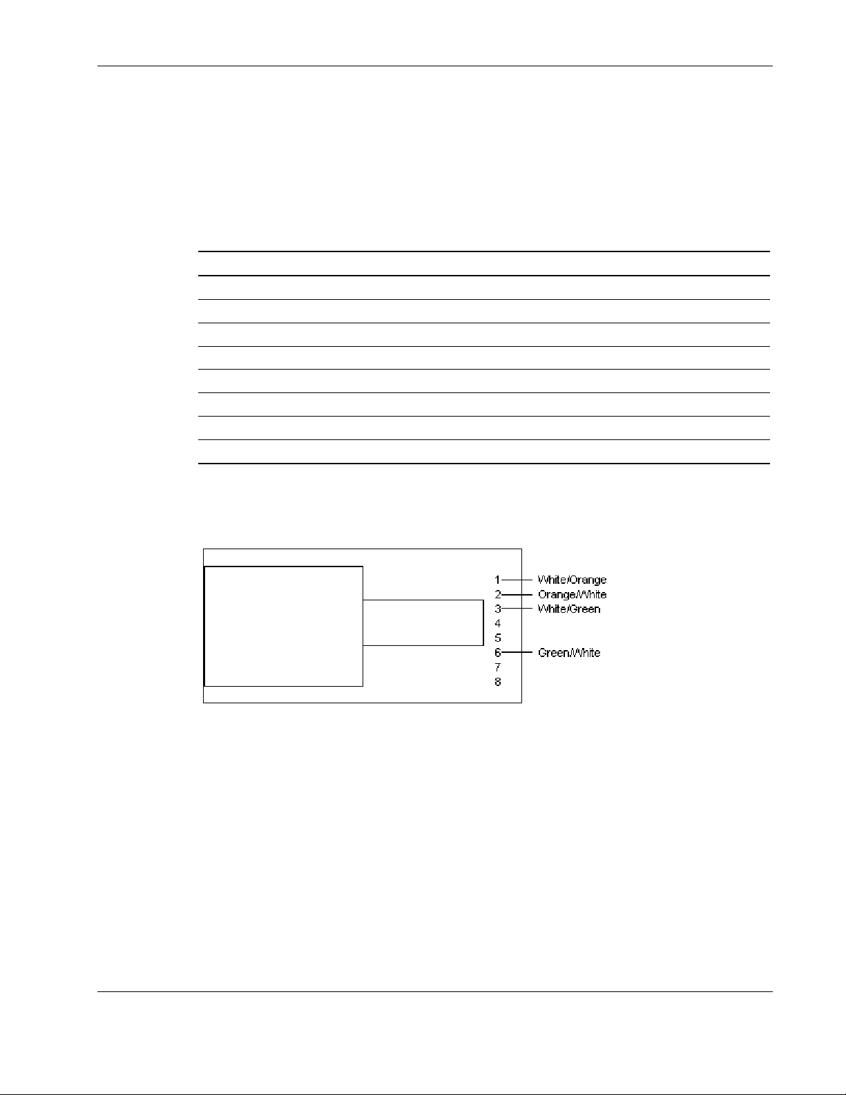
10/100 Straight-Through Pinouts
When the crossover function is implemented internally, the port is labeled MDI-X (Medium
Dependent Interface-Crossover). When an MDI-X port is connected to an MDI port, the
twisted pair media should be wired straight-through using the physical pinouts indicated in
Table C-2.
Table C-2: 10/100 Pinouts Using Internal, Straight-Through Crossover
Pin Function Color Match Function Pin
1 TD+ White/Orange TD+ 1
2 TD- Orange/White TD- 2
3 RD+ White/Green RD+ 3
4 Blue/White 4
5 White/Blue 5
6 RD- Green/White RD- 6
7 White/Brown 7
8 Brown/White 8
Specifications
Figure C-1 shows the straight-through 10/100 connector wiring to be used when the crossover
function is implemented on the hub or switch.
Figure C-1: 10/100 straight-through wiring for RJ-45 connector
HP NC320T PCI Express Gigabit Server Adapter User Guide C-3
Page 19
Specifications
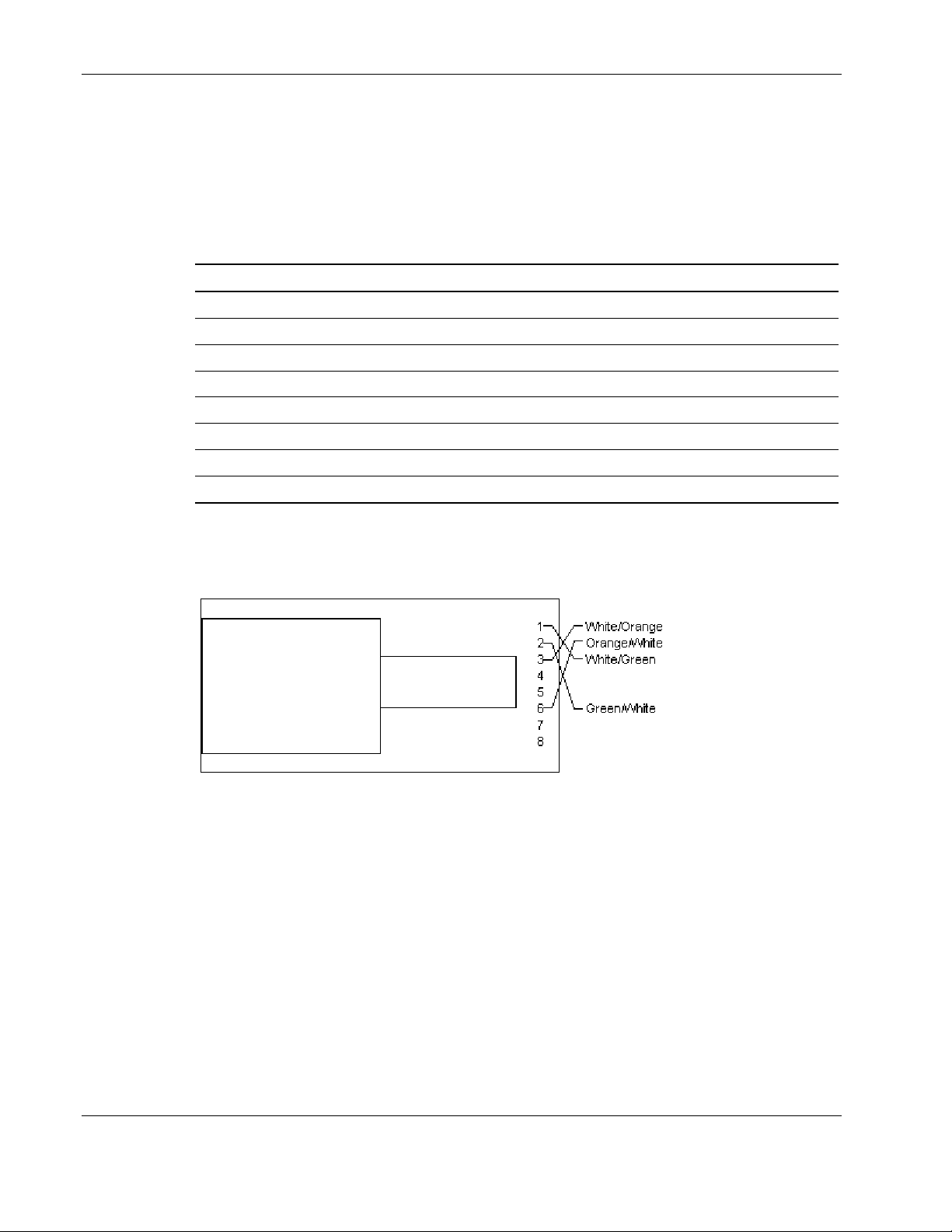
10/100 Crossover Pinouts
When the crossover function is not implemented internally at the hub or switch, you must
implement the crossover through the twisted-pair media using the physical pinouts indicated
in Table C-3.
Table C-3: 10/100 Pinouts Using External Crossover
Pin Function Color/Match Function Pin
1 TD+ White/Orange RD+ 3
2 TD- Orange/White RD- 6
3 RD+ White/Green TD+ 1
4 Blue/White
5 White/Blue
6 RD- Green/White TD- 2
7 White/Brown
8 Brown/White
Figure C-2 shows the correct wiring to use when the crossover function is implemented
externally in the twisted-pair cabling.
Figure C-2: 10/100 external crossover for RJ-45 connector
C-4 HP NC320T PCI Express Gigabit Server Adapter User Guide
Page 20
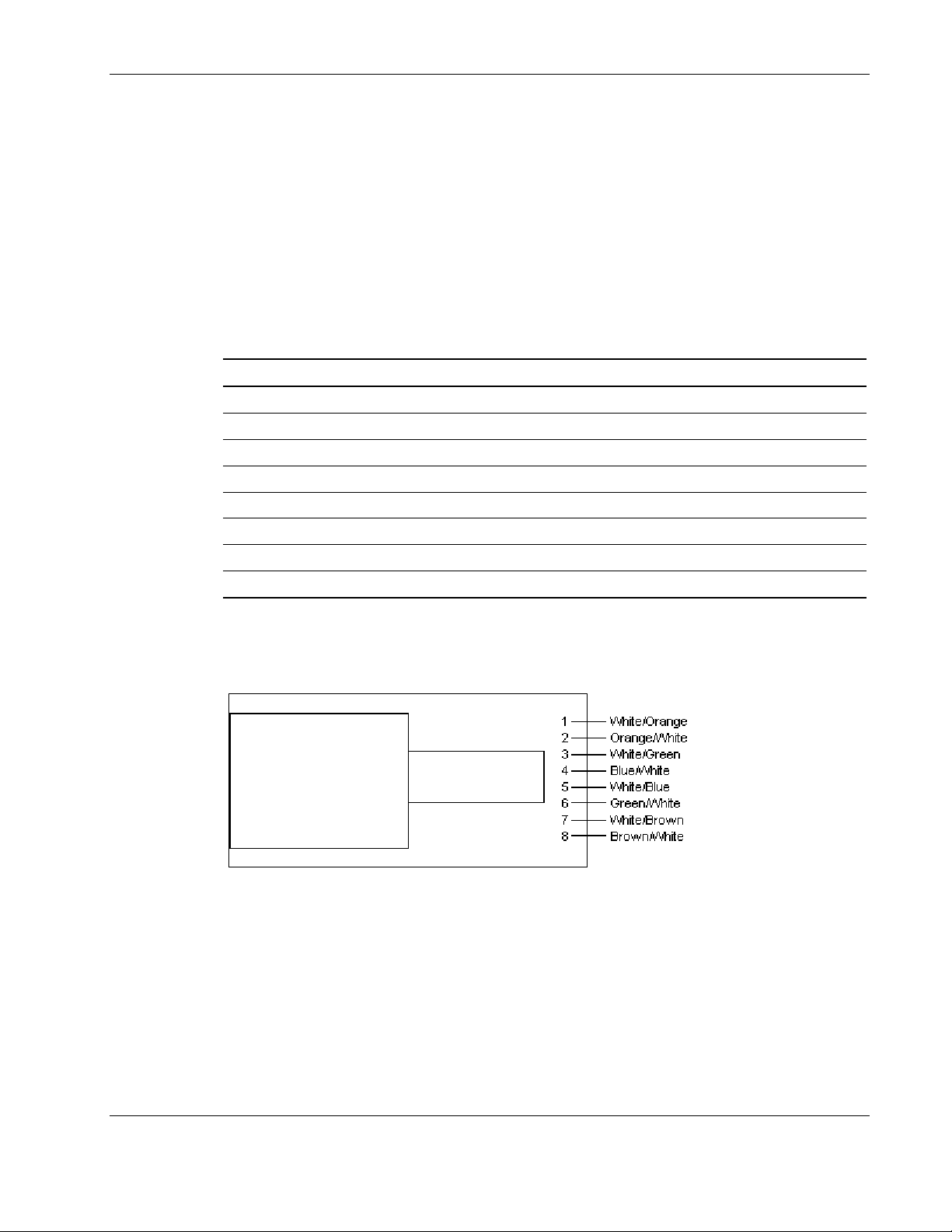
Gigabit over Copper Internal Straight-Through Pinouts
Unlike connections in which the crossover function is implemented internally at the hub or
switch, the NC320T PCI Express Gigabit Server Adapter provides its own automatic
crossover function. This means you can wire twisted-pair media straight-through for adapterto-hub, adapter-to-switch, or adapter-to-adapter connections using the pinouts shown in Table
C-4.
NOTE: To operate at Gigabit speeds, all four pairs of wires must be terminated within the RJ-45
connector.
Table C-4: Gigabit over Copper Pinouts Using Internal Crossover
Pin Function Color Match Function Pin
1 BI_DA+ White/Orange BI_DA+ 1
2 BI_DA- Orange/White BI_DA- 2
3 BI_DB+ White/Green BI_DB+ 3
4 BI_DC+ Blue/White BI_DC+ 4
5 BI_DC- White/Blue BI_DC- 5
6 BI_DB- Green/White BI_DB- 6
7 BI_DD+ White/Brown BI_DD+ 7
8 BI_DD- Brown/White BI_DD- 8
Specifications
Figure C-3 shows straight-through Gigabit over copper connector wiring to be used when the
crossover function is implemented within the hub or switch.
Figure C-3: Gigabit straight-through wiring for RJ-45 connector
HP NC320T PCI Express Gigabit Server Adapter User Guide C-5
Page 21
Specifications
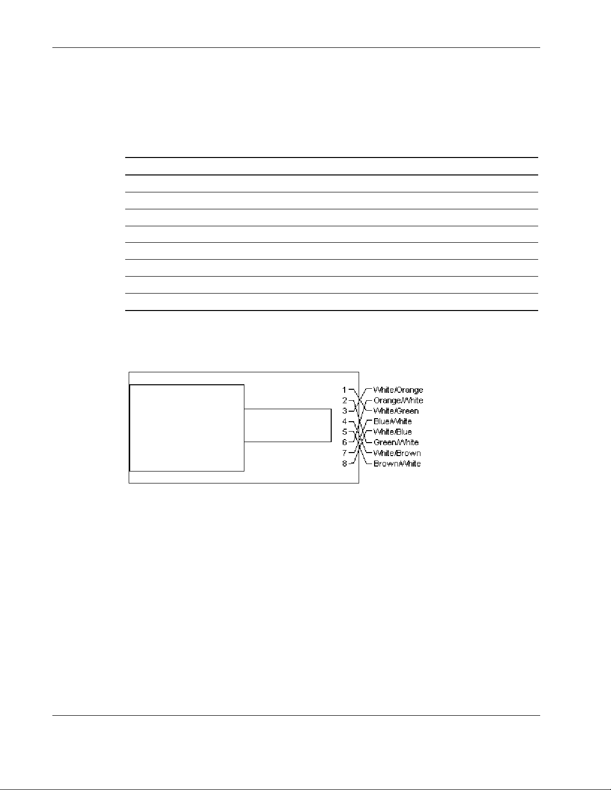
Gigabit over Copper External Crossover Pinouts
When a crossover function is not provided by the adapter, hub or switch, you must implement
it through the twisted-pair media using the physical pinouts shown in Table C-5.
Table C-5: Gigabit over Copper Crossover Pinouts
Pin Function Color Match Function Pin
1 BI_DA+ White/Orange BI_DB+ 3
2 BI_DA- Orange/White BI_DB- 6
3 BI_DB+ White/Green BI_DA+ 1
4 BI_DC+ Blue/White BI_DD+ 7
5 BI_DC- White/Blue BI_DD- 8
6 BI_DB- Green/White BI_DA- 2
7 BI_DD+ White/Brown BI_DC+ 4
8 BI_DD- Brown/White BI_DC- 5
Figure C-4 shows the Gigabit over copper wiring to be used when the crossover function is
implemented externally in the twisted-pair cabling.
Figure C-4: Gigabit over copper external crossover for RJ-45
connector
C-6 HP NC320T PCI Express Gigabit Server Adapter User Guide
 Loading...