

Page 1

HP mt42 Mobile Thin Client
Maintenance and Service Guide
Page 2

© Copyright 2015 HP Development Company,
L.P.
AMD and AMD Radeon are trademarks of
Advanced Micro Devices, Inc. Bluetooth is a
trademark owned by its proprietor and used by
HP Inc. under license. Microsoft and Windows
are either registered trademarks or trademarks
of Microsoft Corporation in the United States
and/or other countries.
The information contained herein is subject to
change without notice. The only warranties for
HP products and services are set forth in the
express warranty statements accompanying
such products and services. Nothing herein
should be construed as constituting an
additional warranty. HP shall not be liable for
technical or editorial errors or omissions
contained herein.
First Edition: October 2015
Document Part Number: 813464-001
Product notice
This user guide describes features that are
common to most models. Some features may
not be available on your computer.
Software terms
By installing, copying, downloading, or
otherwise using any software product
preinstalled on this computer, you agree to be
bound by the terms of the HP End User License
Agreement (EULA). If you do not accept these
license terms, your sole remedy is to return the
entire unused product (hardware and software)
within 14 days for a full refund subject to the
refund policy of your seller.
For any further information or to request a full
refund of the price of the computer, please
contact your seller.
Page 3

Important Notice about Customer Self-Repair Parts
CAUTION: Your computer includes Customer Self-Repair parts and parts that should only be accessed by an
authorized service provider. See Chapter 5, "Removal and replacement procedures for Customer Self-Repair
parts," for details. Accessing parts described in Chapter 6, "Removal and replacement procedures for
Authorized Service Provider only parts," can damage the computer or void your warranty.
iii
Page 4

iv Important Notice about Customer Self-Repair Parts
Page 5

Safety warning notice
WARNING! To reduce the possibility of heat-related injuries or of overheating the device, do not place the
device directly on your lap or obstruct the device air vents. Use the device only on a hard, at surface. Do not
allow another hard surface, such as an adjoining optional printer, or a soft surface, such as pillows or rugs or
clothing, to block airow. Also, do not allow the AC adapter to contact the skin or a soft surface, such as
pillows or rugs or clothing, during operation. The device and the AC adapter comply with the user-accessible
surface temperature limits dened by the International Standard for Safety of Information Technology
Equipment (IEC 60950-1).
v
Page 6

vi Safety warning notice
Page 7

Table of contents
1 Product description ....................................................................................................................................... 1
2 External component identication .................................................................................................................. 4
Right ....................................................................................................................................................................... 4
Left ......................................................................................................................................................................... 5
Display .................................................................................................................................................................... 6
Top .......................................................................................................................................................................... 7
TouchPad ............................................................................................................................................. 7
Lights ................................................................................................................................................... 8
Buttons and speakers .......................................................................................................................... 9
Keys ................................................................................................................................................... 10
Bottom ................................................................................................................................................................. 12
Front ..................................................................................................................................................................... 13
Locating system information .............................................................................................................................. 13
3 Illustrated parts catalog .............................................................................................................................. 15
Computer major components .............................................................................................................................. 15
Display assembly subcomponents ...................................................................................................................... 18
Plastics kit ............................................................................................................................................................ 19
Miscellaneous parts ............................................................................................................................................. 19
4 Removal and replacement procedures preliminary requirements .................................................................... 21
Tools required ...................................................................................................................................................... 21
Service considerations ......................................................................................................................................... 21
Plastic parts ....................................................................................................................................... 21
Cables and connectors ...................................................................................................................... 22
Drive handling ................................................................................................................................... 22
Grounding guidelines ........................................................................................................................................... 23
Electrostatic discharge damage ........................................................................................................ 23
Packaging and transporting guidelines .......................................................................... 24
Workstation guidelines ................................................................................................... 24
Equipment guidelines ..................................................................................................... 25
5 Removal and replacement procedures for Customer Self-Repair parts ............................................................. 26
Component replacement procedures .................................................................................................................. 26
Bottom cover ..................................................................................................................................... 26
vii
Page 8

Battery ............................................................................................................................................... 29
SSD ..................................................................................................................................................... 30
Memory modules ............................................................................................................................... 31
WLAN/Bluetooth combo card ............................................................................................................ 33
WWAN module ................................................................................................................................... 35
Keyboard ........................................................................................................................................... 37
6 Removal and replacement procedures for Authorized Service Provider parts ................................................... 40
Component replacement procedures .................................................................................................................. 40
RTC battery ........................................................................................................................................ 41
Internal base plate ............................................................................................................................ 42
Heat sink/fan assembly .................................................................................................................... 44
Power button board .......................................................................................................................... 46
Touchpad button board ..................................................................................................................... 47
USB/audio board ................................................................................................................................ 48
System board .................................................................................................................................... 49
Speaker assembly ............................................................................................................................. 51
Display assembly ............................................................................................................................... 52
Top cover ........................................................................................................................................... 56
7 Computer Setup (BIOS) and MultiBoot ........................................................................................................... 57
Using Computer Setup ......................................................................................................................................... 57
Starting Computer Setup .................................................................................................................. 57
Navigating and selecting in Computer Setup ................................................................................... 57
Restoring factory settings in Computer Setup ................................................................................. 58
Updating the BIOS ............................................................................................................................. 58
Determining the BIOS version ......................................................................................... 58
Downloading a BIOS update ........................................................................................... 59
Using MultiBoot ................................................................................................................................................... 59
About the boot device order ............................................................................................................. 59
Choosing MultiBoot preferences ....................................................................................................... 60
Setting a new boot order in Computer Setup ................................................................. 60
Dynamically choosing a boot device using the f9 prompt ............................................. 60
Setting a MultiBoot Express prompt .............................................................................. 61
Entering MultiBoot Express preferences ........................................................................ 61
Using HP Sure Start (select models only) ............................................................................................................ 61
8 Using HP PC Hardware Diagnostics (UEFI) ....................................................................................................... 62
Downloading HP PC Hardware Diagnostics (UEFI) to a USB device .................................................................... 62
viii
Page 9

9 Device management .................................................................................................................................... 64
10 Diagnostics and Troubleshooting ................................................................................................................ 65
LEDs ..................................................................................................................................................................... 65
Wake-on LAN ....................................................................................................................................................... 65
Power-On Sequence ............................................................................................................................................ 66
Power-On Diagnostic Tests .................................................................................................................................. 66
Troubleshooting ................................................................................................................................................... 66
Basic Troubleshooting ....................................................................................................................... 66
Conguring a PXE Server ..................................................................................................................................... 67
11 Restoring the Flash Image .......................................................................................................................... 68
System Requirements ......................................................................................................................................... 68
Getting Started .................................................................................................................................................... 68
Formatting a USB Flash Drive .............................................................................................................................. 68
Unpacking the Image and Tools for Deployment ................................................................................................ 69
Deploying with PXE .............................................................................................................................................. 69
12 Adding an Image Restore Tool ..................................................................................................................... 70
13 Power cord set requirements ...................................................................................................................... 71
Requirements for all countries ............................................................................................................................ 71
Requirements for specic countries and regions ................................................................................................ 71
14 Statement of memory volatility .................................................................................................................. 73
Nonvolatile memory usage ................................................................................................................................. 75
Questions and answers ....................................................................................................................................... 77
Using HP Sure Start (select models only) ............................................................................................................ 78
15 Specications ............................................................................................................................................ 79
Input power .......................................................................................................................................................... 79
Operating environment ....................................................................................................................................... 79
16 Recycling .................................................................................................................................................. 80
Index ............................................................................................................................................................. 81
ix
Page 10

x
Page 11

1 Product description
Category Description
Product Name HP mt42 Mobile Thin Client
Processors
Graphics Internal graphics:
Panel 35.6-cm (14-in), eDP 1.2 slim, full high-denition (FHD), AntiGlare (AG), SVA (1920 x 1080) display
Memory Two customer accessible memory module slots
Primary storage M.2 (NGFF) 2242 solid-state drive
Audio and video Conexant smart amplier and ambient noise suppression
Ethernet Broadcom 5762 10/100/1000 Ethernet NIC with DASH Support
AMD® Carrizo processor:
A8 Pro-8600B 1.6 GHz (max turbo frequency 3 GHz), DDR3-2133, 2 MB L2 Cache, 15 W) with Radeon R6
graphics
AMD UMA graphics (with shared video memory)
Up to three independent displays supported with docking solution
DDR3L -12800 (1600 MHz) dual channel support
Supports up to 4 GB of system RAM (4096 MB (4096 MB×1))
M.2 (2242) 32 GB SATA-3
Dual-array microphone
Premium stereo speakers
Webcam (720p)
S3/S4/S5 Wake-on-LAN
Wireless WLAN
Integrated wireless local area network (WLAN) options by way of wireless module
Two WLAN antennas built into display assembly
Supports disabled Bluetooth
Intel Pro Wireless Display (WiDi Pro)
Compatible with Miracast-certied devices
Supports the following WLAN module:
●
WWAN
Integrated wireless wide area network (WWAN) options by way of wireless module
Two WWAN antennas built into display assembly
Supports the following WWAN module:
●
Broadcom 43228 dual-band 802.11abgn 2x2 Wi-Fi Adapter + BT 4.0 combo adapter
Huawei MU736 HSPA+ with GPS M.2 (NGFF)
1
Page 12

Category Description
●
HP lt4120 LTE/EVDO/HSPA+ SnapdragonT X5 LTE Mobile Broadband Module
External media cards Micro SIM card reader
Memory card reader (SD, SDHC, SDXC)
Ports VGA (Dsub 15 pin) supporting 1920x1200 external resolution @ 75Hz; hot plug/unplug and auto detect
USB 3.0 charging port
USB 3.0 port
USB Type-C port
DisplayPort
RJ-45
Docking connector
Audio-out (headphone)/audio-in (microphone) combo jack
AC port
Keyboard/pointing
devices
Power requirements AC adapter:
Keyboard:
Dual point
Spill resistant with drain
TouchPad:
Gestures enabled by default: two-nger scrolling, two-nger pinch-zoom
Taps enabled by default
On/o button
Supports 2-way scroll w/ legend
Mylar
65 W HP Smart AC adapter
45 W HP Smart AC adapter
45 W, 2-prong AC adapter
Power cord:
2-wire cord, 1.0 m
3-wire cord, 1.0 m (with ground pin)
3-wire cord, 1.8 m (with ground pin)
Security Security lock
Operating system Preinstalled:
2 Chapter 1 Product description
Supports Trusted Platform Module (TPM) 1.2 or 2.0 (Inneon, soldered down)
Integrated Smart Card reader (active)
Preboot authentication (password, smart card)
Windows Embedded Standard 7E (32-bit)
Web-only support
Page 13

Category Description
Windows Embedded Standard 7E (32-bit)
Serviceability End user replaceable parts:
AC adapter
Battery
M.2 SSD
Memory module
WLAN
WWAN
Keyboard
3
Page 14
2 External component identication
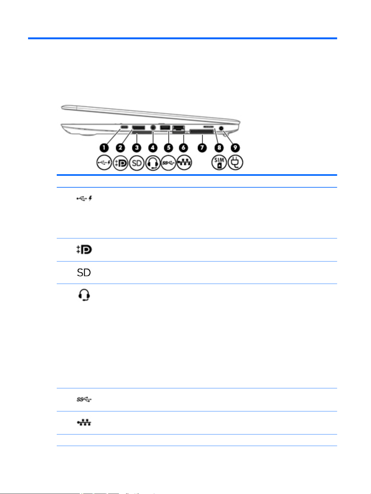
Right
Component Description
(1) USB Type-C (charging) port Connects any USB device with a Type-C connector.
NOTE: USB Type-C ports charge products such as cell phones,
laptops, tablets, and MP3 players, even when the computer is
o. Also, some USB Type-C ports connect DisplayPort, VGA,
HDMI and other video devices to provide video output.
NOTE: Adapters (purchased separately) may be required.
(2) Dual-Mode DisplayPort Connects an optional digital display device, such as a high-
performance monitor or projector.
(3) Memory card reader Reads optional memory cards that store, manage, share, or
access information.
(4) Audio-out (headphone)/Audio-in (microphone)
jack
(5) USB 3.0 port Connects an optional USB device, such as a keyboard, mouse,
(6) RJ-45 (network) jack Connects a network cable.
Connects optional powered stereo speakers, headphones,
earbuds, a headset, or a television audio cable. Also connects an
optional headset microphone. This jack does not support
optional microphone-only devices.
WARNING! To reduce the risk of personal injury, adjust the
volume before putting on headphones, earbuds, or a headset.
For additional safety information, see the Regulatory, Safety,
and Environmental Notices. To access the user guides, select
Start > HP > HP Documentation.
NOTE: When a device is connected to the jack, the computer
speakers are disabled.
NOTE: Be sure that the device cable has a 4-conductor
connector that supports both audio-out (headphone) and
audio-in (microphone).
external drive, printer, scanner or USB hub.
(7) Docking connector Connects an optional docking device.
4 Chapter 2 External component identication
Page 15
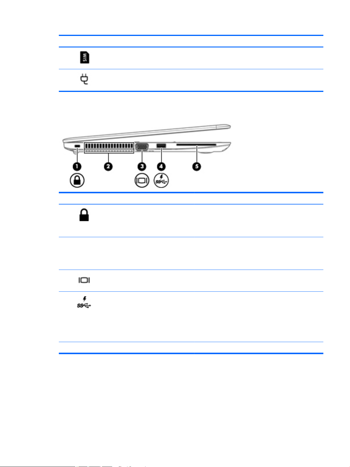
Left
Component Description
(8) SIM slot Supports a wireless subscriber identity module (SIM) card.
(9) Power connector Connects an AC adapter.
Component Description
(1) Security cable slot Attaches an optional security cable to the computer.
NOTE: The security cable is designed to act as a deterrent, but
it may not prevent the computer from being mishandled or
stolen.
(2) Vents (2) Enable airow to cool internal components.
NOTE: The computer fan starts up automatically to cool
internal components and prevent overheating. It is normal for
the internal fan to cycle on and o during routine operation.
(3) External monitor port Connects an external VGA monitor or projector.
(4) USB 3.0 charging (powered) port Connects an optional USB device, such as a keyboard, mouse,
external drive, printer, scanner or USB hub. Standard USB ports
will not charge all USB devices or will charge using a low current.
Some USB devices require power and require you to use a
powered port.
NOTE: USB charging ports can also charge select models of
cell phones and MP3 players, even when the computer is o.
(5) Smart card reader Supports optional smart cards.
Left 5
Page 16
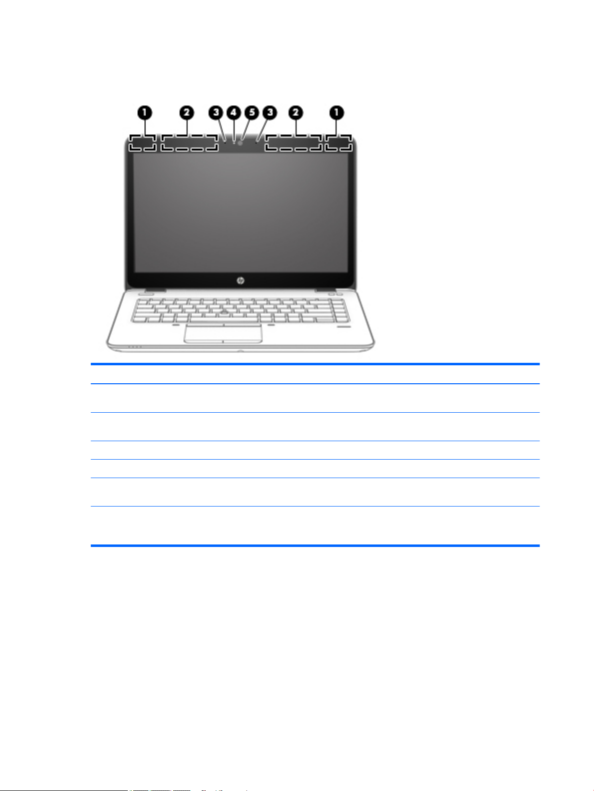
Display
Component Description
(1) WLAN antennas (2)* Send and receive wireless signals to communicate with wireless local
area networks (WLAN).
(2) WWAN antennas (2)* Send and receive wireless signals to communicate with wireless wide
area networks (WWAN).
(3) Internal microphones Record sound.
(4) Webcam light On: The webcam is in use.
(5) Webcam Records video and captures photographs. Some models allow you to
video conference and chat online using streaming video.
*The antennas are not visible on the outside of the computer. For optimal transmission, keep the areas immediately around the
antennas free from obstructions. To see wireless regulatory notices, see the section of the Regulatory, Safety, and Environmental
Notices that applies to your country or region. To access the user guides, select Start > HP > HP Documentation.
6 Chapter 2 External component identication
Page 17
Top
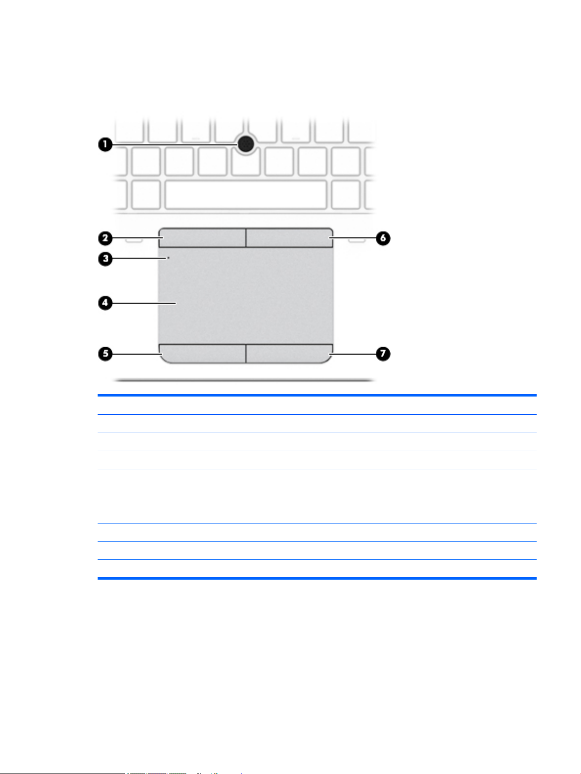
TouchPad
Component Description
(1) Pointing stick (select models only) Moves the pointer and selects or activates items on the screen.
(2) Left pointing stick button (select models only) Functions like the left button on an external mouse.
(3) TouchPad on/o button Turns the TouchPad on and o.
(4) TouchPad zone Moves the pointer and selects or activates items on the screen.
NOTE: The TouchPad also supports edge-swipe gestures. For
more information, see Edge swipes (select models only) on
page 34.
(5) Left TouchPad button Functions like the left button on an external mouse.
(6) Right pointing stick button (select models only) Functions like the right button on an external mouse.
(7) Right TouchPad button Functions like the right button on an external mouse.
Top 7
Page 18

Lights
Component Description
(1) Power light
(2) Microphone mute light
(3) Num lock light On: Num lock is on.
(4) Wireless light On: An integrated wireless device, such as a wireless local area
(5) Mute light
(6) Caps lock light On: Caps lock is on, which switches the keys to all capital letters.
(7) TouchPad light
●
On: The computer is on.
●
Blinking: The computer is in the Sleep state, a power-saving
state. The computer shuts o power to the display and
other unneeded components.
●
O: The computer is o.
●
Amber: microphone sound is o.
●
O: microphone sound is on.
network (WLAN) device and/or a Bluetooth® device, is on.
NOTE: On some models, the wireless light is amber when all
wireless devices are o.
●
Amber: Computer sound is o.
●
O: Computer sound is on.
●
On: The TouchPad is o.
●
O: The TouchPad is on.
8 Chapter 2 External component identication
Page 19

Buttons and speakers
Component Description
(1) Power button
(2) Speakers (2) Produce sound.
(3) Wireless button Turns the wireless feature on or o but does not establish a
(4) Volume mute button Mutes and restores speaker sound.
●
When the computer is o, press the button to turn on the
computer.
●
When the computer is on, press the button briey to initiate
Sleep.
●
When the computer is in the Sleep state, press the button
briey to exit Sleep.
CAUTION: Pressing and holding down the power button will
result in the loss of unsaved information.
If the computer has stopped responding and Windows® shutdown
procedures are ineective, press and hold the power button for at
least 15 seconds to turn o the computer.
To learn more about your power settings: Select Start > Control
Panel > System and Security > Power Options.
wireless connection.
Top 9
Page 20
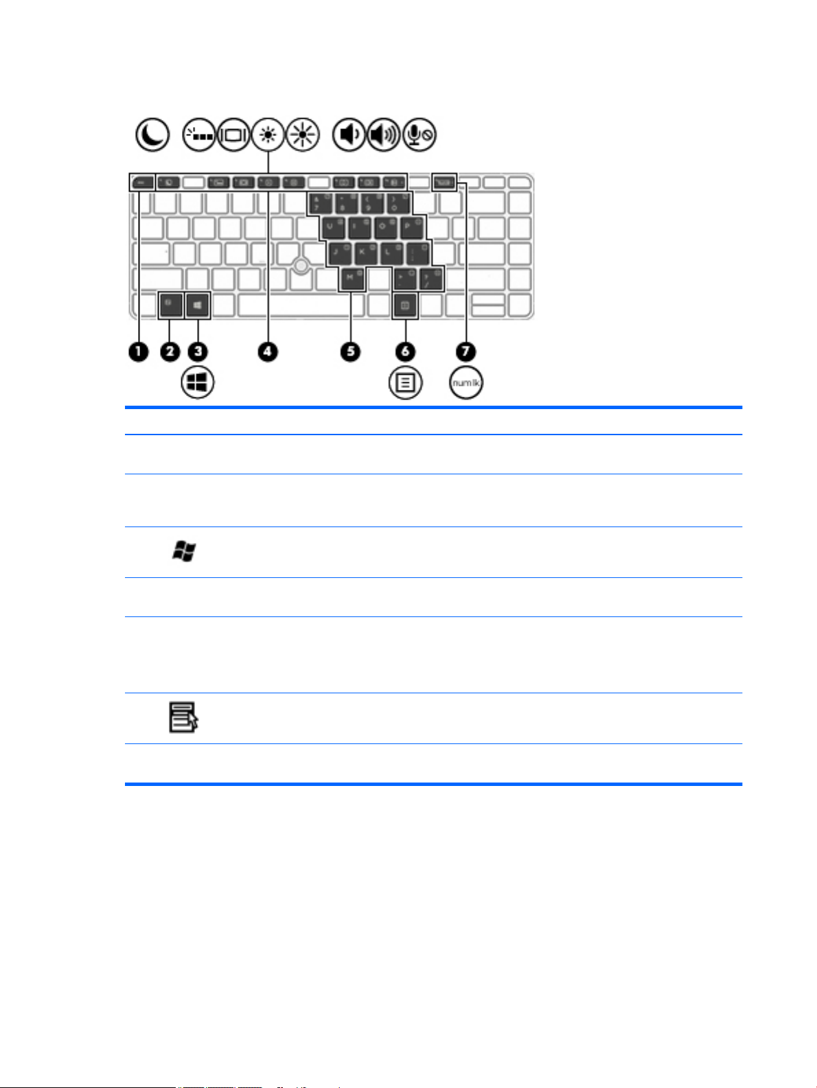
Keys
Component Description
(1) esc key Displays system information when pressed in combination with
the fn key.
(2) fn key Executes frequently used system functions when pressed in
combination with a function key, the num lk key, the esc key, or
the b key.
(3) Windows button Displays the Windows Start menu.
(4) Function keys Execute frequently used system functions when pressed in
combination with the fn key.
(5) Embedded numeric keypad When the keypad is turned on, it can be used like an external
numeric keypad.
Each key on the keypad performs the function indicated by the
icon in the upper-right corner of the key.
(6) Windows applications key Displays a shortcut menu for items beneath the cursor.
(7) num lk key Turns the embedded numeric keypad on and o when pressed in
combination with the fn key.
10 Chapter 2 External component identication
Page 21
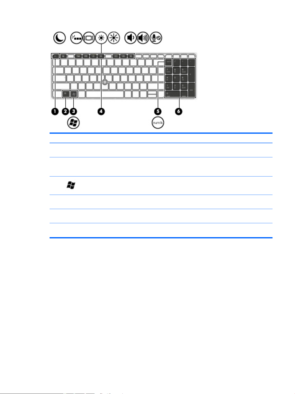
Component Description
(1) esc key Displays system information when pressed in combination with
the fn key.
(2) fn key Executes frequently used system functions when pressed in
combination with a function key, the num lk key, the esc key, or
the b key.
(3) Windows button Displays the Windows Start menu.
(4) Function keys Execute frequently used system functions when pressed in
combination with the fn key.
(5) num lk key Alternates between the navigational and numeric functions on
the integrated numeric keypad.
(6) Integrated numeric keypad When num lk has been enabled, it can be used like an external
numeric keypad.
Top 11
Page 22
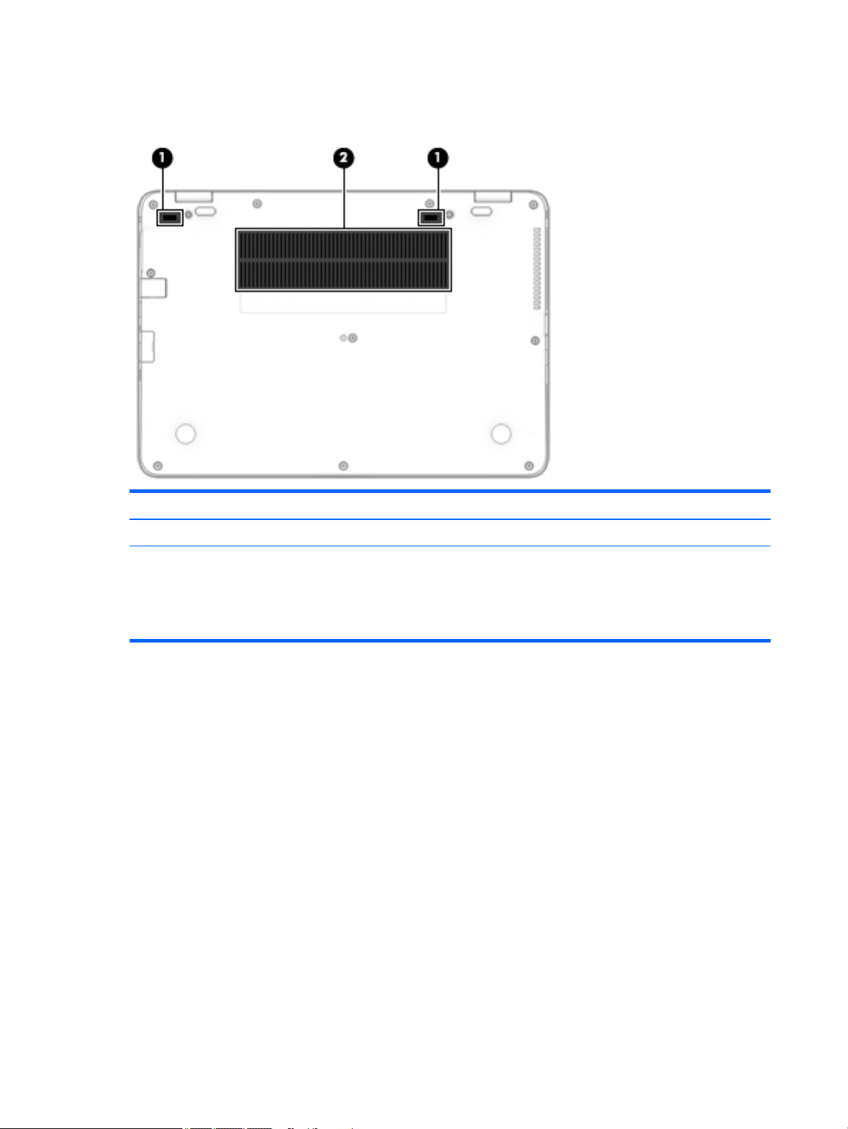
Bottom
Component Description
(1) Docking connectors (2) Connect an optional docking device.
(2) Vents (2) Enable airow to cool internal components.
NOTE: The computer fan starts up automatically to cool
internal components and prevent overheating. It is normal
for the internal fan to cycle on and o during routine
operation.
12 Chapter 2 External component identication
Page 23
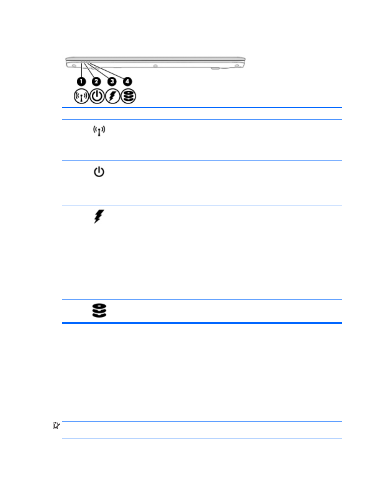
Front
Component Description
(1) Wireless light On: An integrated wireless device, such as a wireless local
area network (WLAN) device and/or a Bluetooth® device, is
on.
NOTE: On some models, the wireless light is amber when
all wireless devices are o.
(2) Power light
(3) Battery light When AC power is connected:
(4) Drive light Blinking white: The hard drive is being accessed.
Locating system information
●
On: The computer is on.
●
Blinking: The computer is in the Sleep state, a powersaving state. The computer shuts o power to the
display and other unneeded components.
●
O: The computer is o.
●
White: The battery charge is greater than 90 percent.
●
Amber: The battery charge is from 0 to 90 percent.
●
O: The battery is not charging.
When AC power is disconnected (battery not charging):
●
Blinking amber: The battery has reached a low
battery level. When the battery has reached a critical
battery level, the battery light begins blinking
rapidly.
●
O: The battery is not charging.
Important system information is located on the bottom edge of the tablet or on the keyboard base. You may
need the information when travelling internationally or when you contact support:
(1): Serial number
(2): Product number
(3): Model number
(4): Warranty period
IMPORTANT: Check the following locations for the labels described in this section: the bottom of the
computer, inside the battery bay, under the service door, or on the back of the display.
Front 13
Page 24
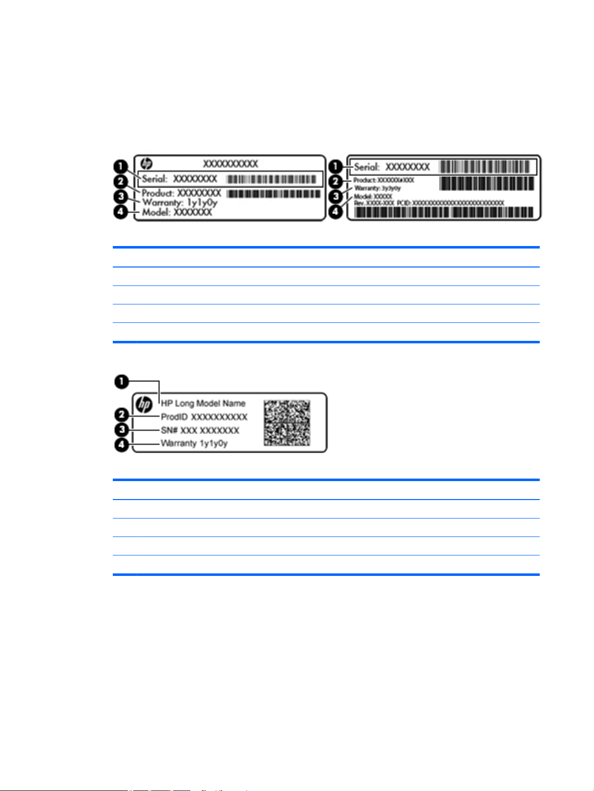
●
Service label—Provides important information to identify your computer. When contacting support, you
will probably be asked for the serial number, and possibly for the product number or the model number.
Locate these numbers before you contact support.
Your service label will resemble one of the examples shown below. Refer to the illustration that most
closely matches the service label on your computer.
Component
(1) Serial number
(2) Product number
(3) Warranty period
(4) Model number (select products only)
Component
(1) Model name (select products only)
(2) Product number
(3) Serial number
(4) Warranty period
●
Regulatory label(s)—Provide(s) regulatory information about the computer.
●
Wireless certication label(s)—Provide(s) information about optional wireless devices and the approval
markings for the countries or regions in which the devices have been approved for use.
Using Windows, briey press the fn+esc key combination to display the System Information screen, which
provides the product name and serial number of your computer, as well as information about the memory,
processor, BIOS, and keyboard.
14 Chapter 2 External component identication
Page 25

3 Illustrated parts catalog
Computer major components
NOTE: HP continually improves and changes product parts. For complete and current information on
supported parts for your computer, go to http://partsurfer.hp.com, select your country or region, and then
follow the on-screen instructions.
NOTE: Details about your computer, including model, serial number, product key, and length of warranty,
are on the service tag at the bottom of your computer. See Locating system information on page 13 for
details.
Computer major components 15
Page 26

16 Chapter 3 Illustrated parts catalog
Page 27

Item Component Spare part number
(1) Display assembly: Display assembly: Non-touch display assemblies are spared at the subcomponent level only. For more
non-touch display assembly spare part information, see Display assembly subcomponents on page 18.
(2) Keyboard (see Keyboard on page 37) 836634-xx1
(3) Top cover 821173-001
(4) Power button board 821169-001
(5) USB/audio board (includes cable) 837846-001
(6) TouchPad 821171-001
(7) Speakers (includes cable) 821170-001
(8) System board (includes processor and replacement thermal material, see System board on page 49)
For use in models with the Windows Embedded Standard operating system 827570-001
For use in models with the Windows 10 IoT Enterprise operating system 827570-601
(9) RTC battery 665733-001
(10) Heat sink/fan assembly 821163-001
(11) Internal base plate not spared
(12) Memory module
4-GB (PC3L-12800, 1600-MHz, DDR3L) 691740-001
(13) WWAN module
HP lt4120 LTE/EVDO/HSPA+ SnapdragonT X5 LTE Mobile Broadband Module 800870-001
Huawei MU736 HSPA+ with GPS M.2 (NGFF) 822828-001
(14) WLAN/Bluetooth combo card
Broadcom 43228 dual-band 802.11abgn 2x2 Wi-Fi Adapter + BT 4.0 combo adapter (not available in
Indonesia)
Broadcom 43228 dual-band 802.11abgn 2x2 Wi-Fi Adapter + BT 4.0 combo adapter (Indonesia only) 812132-001
(15) Solid-state drive (SSD), 2242.M2
32 GB 827578-001
(16) Battery 800513-001
(17) Bottom cover 821162-001
797884-001
Computer major components 17
Page 28
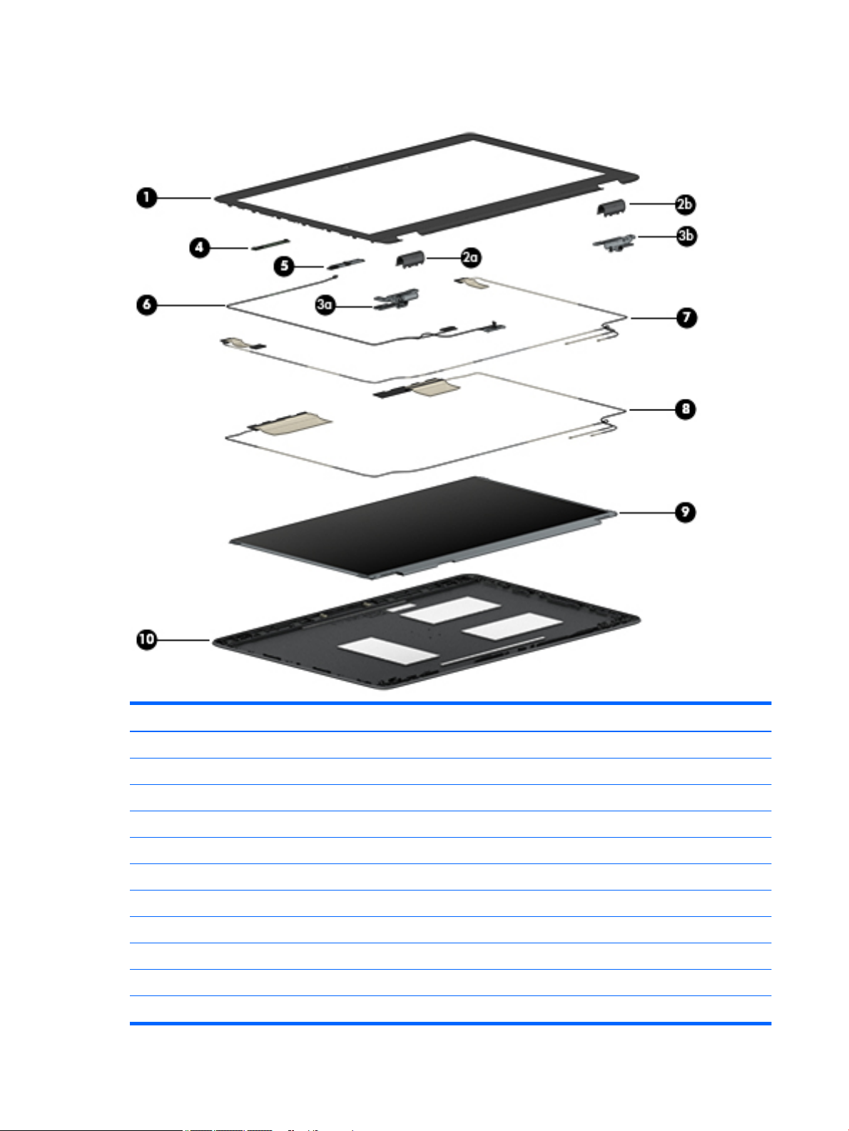
Display assembly subcomponents
Item Component Spare part number
(1) Bezel 821197-001
Hinge kit 821166-001
(2) Left hinge cover (a) and right hinge cover (b) (spared with hinges)
(3) Left hinge (a) and right hinge (b)
(4) Microphone module 821168-001
(5) Webcam module (includes microphone) 821676-001
(6) Display/webcam cable 821174-001
(7) WLAN antenna (spared with back cover)
(8) WWAN antenna (spared with back cover)
(9) Raw panel 823951-001
(10) Back cover (includes antennas) 821161-001
18 Chapter 3 Illustrated parts catalog
Page 29

Plastics kit
Item Component Spare part number
Plastics kit 821175-001
(1) Fingerprint reader blank
(2) SD card blank
Miscellaneous parts
Component Spare part number
AC adapter:
45 W HP Smart AC adapter, nPFC, slim 741727-001
45 W HP Smart AC adapter, nPFC, 2P 742436-001
65 W HP Smart AC adapter, nPFC, emerging markets 714657-001
65 W HP Smart AC adapter, nPFC, S-3P 710412-001
65 W HP Smart AC adapter, nPFC 693711-001
HP Mobile Connect 714749-001
HP DisplayPort to HDMI cable 749288-001
HP Essential Top Load Case 679921-001
HP Professional Slim Top Load Case 703888-001
Cable lock docking station 575921-001
HP USB Laser Mouse 674318-001
HP USB Travel Mouse 757770-001
Power cord (3-pin, black, 1.83 m):
For use in Argentina 490371-D01
For use in Australia 490371-011
Plastics kit 19
Page 30

Component Spare part number
For use in Denmark 490371-081
For use in Europe 490371-021
For use in India 490371-D61
For use in Israel 490371-BB1
For use in Italy 490371-061
For use in Japan 490371-291
For use in North America 490371-001
For use in the People’s Republic of China 490371-AA1
For use in South Korea 490371-AD1
For use in Switzerland 490371-111
For use in Taiwan 490371-AB1
For use in Thailand 490371-201
For use in the United Kingdom 490371-031
Power cord (3-pin, black, 1 m):
For use in Argentina 755530-D01
For use in Australia 755530-011
For use in Brazil 755530-202
For use in Denmark 755530-081
For use in Europe 755530-021
For use in India 755530-D61
For use in Israel 755530-BB1
For use in Italy 755530-061
For use in Japan 755530-291
For use in North America 755530-001
For use in the People’s Republic of China 755530-AA1
For use in South Africa 755530-AR1
For use in South Korea 755530-AD1
For use in Switzerland 755530-111
For use in Taiwan 755530-AB1
For use in Thailand 755530-201
For use in the United Kingdom 755530-031
Power cord (2-pin, black, 1.81 m): For use in Japan 753361-001
Power cord (2-pin, black, 1 m): For use in Japan 762689-291
Screw kit 840070-001
20 Chapter 3 Illustrated parts catalog
Page 31

4 Removal and replacement procedures
preliminary requirements
Tools required
You will need the following tools to complete the removal and replacement procedures:
●
Phillips P0 screwdriver
Service considerations
The following sections include some of the considerations that you must keep in mind during disassembly
and assembly procedures.
NOTE: As you remove each subassembly from the computer, place the subassembly (and all accompanying
screws) away from the work area to prevent damage.
Plastic parts
CAUTION: Using excessive force during disassembly and reassembly can damage plastic parts. Use care
when handling the plastic
Tools required 21
Page 32

Cables and connectors
CAUTION: When servicing the computer, be sure that cables are placed in their proper locations during the
reassembly process. Improper cable placement can damage the computer.
Cables must be handled with extreme care to avoid damage. Apply only the tension required to unseat or seat
the cables during removal and insertion. Handle cables by the connector whenever possible. In all cases, avoid
bending, twisting, or tearing cables. Be sure that cables are routed in such a way that they cannot be caught
or snagged by parts being removed or replaced. Handle ex cables with extreme care; these cables tear
easily.
Drive handling
CAUTION: Drives are fragile components that must be handled with care. To prevent damage to the
computer, damage to a drive, or loss of information, observe these precautions:
Before removing or inserting a hard drive, shut down the computer. If you are unsure whether the computer is
o or in Hibernation, turn the computer on, and then shut it down through the operating system.
Before handling a drive, be sure that you are discharged of static electricity. While handling a drive, avoid
touching the connector.
Before removing a diskette drive or optical drive, be sure that a diskette or disc is not in the drive and be sure
that the optical drive tray is closed.
Handle drives on surfaces covered with at least one inch of shock-proof foam.
Avoid dropping drives from any height onto any surface.
Avoid exposing an internal hard drive to products that have magnetic elds, such as monitors or speakers.
Avoid exposing an internal hard drive to products that have magnetic elds, such as monitors or speakers.
Avoid exposing a drive to temperature extremes or liquids.
If a drive must be mailed, place the drive in a bubble pack mailer or other suitable form of protective
packaging and label the package “FRAGILE.”
22 Chapter 4 Removal and replacement procedures preliminary requirements
Page 33

Grounding guidelines
Electrostatic discharge damage
Electronic components are sensitive to electrostatic discharge (ESD). Circuitry design and structure determine
the degree of sensitivity. Networks built into many integrated circuits provide some protection, but in many
cases, ESD contains enough power to alter device parameters or melt silicon junctions.
A discharge of static electricity from a nger or other conductor can destroy static-sensitive devices or
microcircuitry. Even if the spark is neither felt nor heard, damage may have occurred.
An electronic device exposed to ESD may not be aected at all and can work perfectly throughout a normal
cycle. Or the device may function normally for a while, then degrade in the internal layers, reducing its life
expectancy.
CAUTION: To prevent damage to the computer when you are removing or installing internal components,
observe these precautions:
Keep components in their electrostatic-safe containers until you are ready to install them.
Before touching an electronic component, discharge static electricity by using the guidelines described in this
section.
Avoid touching pins, leads, and circuitry. Handle electronic components as little as possible.
If you remove a component, place it in an electrostatic-safe container.
The following table shows how humidity aects the electrostatic voltage levels generated by dierent
activities.
CAUTION: A product can be degraded by as little as 700 V.
Typical electrostatic voltage levels
Relative humidity
Event 10% 40% 55%
Walking across carpet 35,000 V 15,000 V 7,500 V
Walking across vinyl oor 12,000 V 5,000 V 3,000 V
Motions of bench worker 6,000 V 800 V 400 V
Removing DIPS from plastic tube 2,000 V 700 V 400 V
Removing DIPS from vinyl tray 11,500 V 4,000 V 2,000 V
Removing DIPS from Styrofoam 14,500 V 5,000 V 3,500 V
Removing bubble pack from PCB 26,500 V 20,000 V 7,000 V
Packing PCBs in foam-lined box 21,000 V 11,000 V 5,000 V
Grounding guidelines 23
Page 34

Packaging and transporting guidelines
Follow these grounding guidelines when packaging and transporting equipment:
●
To avoid hand contact, transport products in static-safe tubes, bags, or boxes.
●
Protect ESD-sensitive parts and assemblies with conductive or approved containers or packaging.
●
Keep ESD-sensitive parts in their containers until the parts arrive at static-free workstations.
●
Place items on a grounded surface before removing items from their containers.
●
Always be properly grounded when touching a component or assembly.
●
Store reusable ESD-sensitive parts from assemblies in protective packaging or nonconductive foam.
●
Use transporters and conveyors made of antistatic belts and roller bushings. Be sure that mechanized
equipment used for moving materials is wired to ground and that proper materials are selected to avoid
static charging. When grounding is not possible, use an ionizer to dissipate electric charges.
Workstation guidelines
Follow these grounding workstation guidelines:
●
Cover the workstation with approved static-shielding material.
●
Use a wrist strap connected to a properly grounded work surface and use properly grounded tools and
equipment.
●
Use conductive eld service tools, such as cutters, screwdrivers, and vacuums.
●
When xtures must directly contact dissipative surfaces, use xtures made only of static safe materials.
●
Keep the work area free of nonconductive materials, such as ordinary plastic assembly aids and
Styrofoam.
●
Handle ESD-sensitive components, parts, and assemblies by the case or PCM laminate. Handle these
items only at static-free workstations.
●
Avoid contact with pins, leads, or circuitry.
●
Turn o power and input signals before inserting or removing connectors or test equipment.
24 Chapter 4 Removal and replacement procedures preliminary requirements
Page 35

Equipment guidelines
Grounding equipment must include either a wrist strap or a foot strap at a grounded workstation.
●
When seated, wear a wrist strap connected to a grounded system. Wrist straps are exible straps with a
minimum of one megohm ±10% resistance in the ground cords. To provide proper ground, wear a strap
snugly against the skin at all times. On grounded mats with banana-plug connectors, use alligator clips
to connect a wrist strap.
●
When standing, use foot straps and a grounded oor mat. Foot straps (heel, toe, or boot straps) can be
used at standing workstations and are compatible with most types of shoes or boots. On conductive
oors or dissipative oor mats, use foot straps on both feet with a minimum of one megohm resistance
between the operator and ground. To be eective, the conductive must be worn in contact with the skin.
The following grounding equipment is recommended to prevent electrostatic damage:
●
Antistatic tape
●
Antistatic smocks, aprons, and sleeve protectors
●
Conductive bins and other assembly or soldering aids
●
Nonconductive foam
●
Conductive tabletop workstations with ground cords of one megohm resistance
●
Static-dissipative tables or oor mats with hard ties to the ground
●
Field service kits
●
Static awareness labels
●
Material-handling packages
●
Nonconductive plastic bags, tubes, or boxes
●
Metal tote boxes
●
Electrostatic voltage levels and protective materials
The following table lists the shielding protection provided by antistatic bags and oor mats.
Material Use Voltage protection level
Antistatic plastics Bags 1,500 V
Carbon-loaded plastic Floor mats 7,500 V
Metallized laminate Floor mats 5,000 V
Grounding guidelines 25
Page 36

5 Removal and replacement procedures for
Customer Self-Repair parts
This chapter provides removal and replacement procedures for Customer Self-Repair parts.
NOTE: The Customer Self-Repair program is not available in all locations. Installing a part not supported by
the Customer Self-Repair program may void your warranty. Check your warranty to determine if Customer
Self-Repair is supported in your location.
Component replacement procedures
NOTE: Details about your computer, including model, serial number, product key, and length of warranty,
are on the service tag at the bottom of your computer. See Locating system information on page 13 for
details.
NOTE: HP continually improves and changes product parts. For complete and current information on
supported parts for your computer, go to http://partsurfer.hp.com, select your country or region, and then
follow the on-screen instructions.
There are as many as 22 screws that must be removed, replaced, and/or loosened when servicing Customer
Self-Repair parts. Make special note of each screw size and location during removal and replacement.
Bottom cover
Description Spare part number
Bottom cover 821162-001
Before removing the bottom cover, follow these steps:
1. Turn o the computer. If you are unsure whether the computer is o or in Hibernation, turn the
computer on, and then shut it down through the operating system.
2. Disconnect the power from the computer by unplugging the power cord from the computer.
3. Disconnect all external devices from the computer.
Remove the bottom cover:
1. Turn the computer upside down on a at surface.
26 Chapter 5 Removal and replacement procedures for Customer Self-Repair parts
Page 37
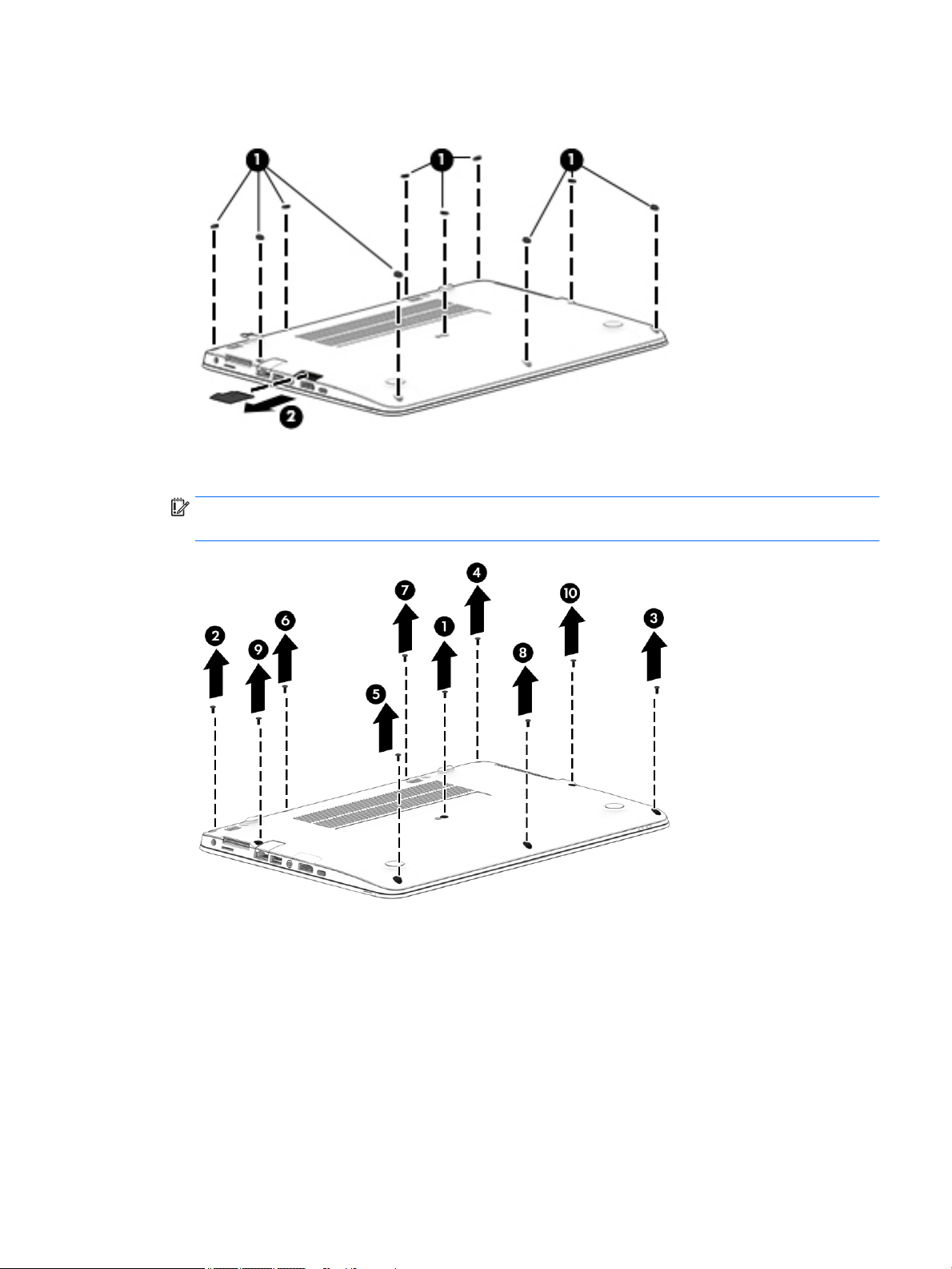
2. Remove the 10 rubber plugs (1) and the SD card blank (2) from the bottom cover.
3. In the order indicated in the following image, remove the 10 Phillips PM2.5×5.0 screws that secure the
bottom cover to the computer.
IMPORTANT: To make sure the bottom cover installs properly, be sure to remove and replace the
screws in the order shown in the following image.
Component replacement procedures 27
Page 38

4. Pry up on the top (near the display hinge) of the bottom cover to disengage it from the computer.
Reverse the removal procedures to install the bottom cover.
NOTE: There are ve dierent sizes of rubber plugs. Be sure that you reinstall them over the correct screws.
The rubber-plug sizes are as follows.
The rubber-plug locations are as follows.
28 Chapter 5 Removal and replacement procedures for Customer Self-Repair parts
Page 39

Battery
Description Spare part number
3-cell, 46 WHr, 4.08 Ah Li-ion battery 800513-001
Before removing the battery, follow these steps:
1. Shut down the computer. If you are unsure whether the computer is o or in Hibernation, turn the
computer on, and then shut it down through the operating system.
2. Disconnect all external devices connected to the computer.
3. Disconnect the power from the computer by rst unplugging the power cord from the AC outlet, and
then unplugging the AC adapter from the computer.
4. Remove the bottom cover (see Bottom cover on page 26).
To remove the battery:
CAUTION: Removing a battery that is the sole power source for the computer can cause loss of information.
To prevent loss of information, save your work and shut down the computer through Windows before
removing the battery.
▲
Loosen the two captive screws (1) and remove the battery from the computer (2).
Reverse the removal procedures to install the battery.
Component replacement procedures 29
Page 40

SSD
Description Spare part number
Solid-state drive, 2242.M2
32 GB 827578-001
Before removing the SSD, follow these steps:
1. Turn o the computer. If you are unsure whether the computer is o or in Hibernation, turn the
computer on, and then shut it down through the operating system.
2. Disconnect the power from the computer by unplugging the power cord from the computer.
3. Disconnect all external devices from the computer.
4. Remove the bottom cover (see Bottom cover on page 26).
5. Disconnect the battery (see Battery on page 29).
Remove the SSD:
1. Remove the Phillips PM2.0×3.0 screw (1) that secures the drive to the system board.
2. Remove the drive (2) by pulling it away from the connector.
NOTE: mSATA drives are designed with notches to prevent incorrect insertion.
Reverse this procedure to reassemble and install the mSATA drive.
30 Chapter 5 Removal and replacement procedures for Customer Self-Repair parts
Page 41

Memory modules
NOTE: Primary and expansion memory is installed in a side-by-side conguration in the bottom of the
computer.
If only one memory module is installed, it must be installed in the socket labeled 1.
Description Spare part number
4-GB (PC3L-12800, 1600-MHz, DDR3L) 691740-001
Update BIOS before adding memory modules
Before adding new memory, make sure you update the computer to the latest BIOS.
CAUTION: Failure to update the computer to the latest BIOS prior to installing new memory may result in
various system problems.
To update BIOS:
1. Navigate to www.hp.com.
2. Click Support & Drivers > click Drivers & Software.
3. In the Enter a product name/number box, type the computer model information, and then click Search.
4. Click the link for the computer model.
5. Select the operating system, and then click Next.
6. Under Step 2: Select a Download, click the BIOS link.
7. Click the link for the most recent BIOS.
8. Click the Download button, and then follow the on-screen instructions.
Before removing the memory module, follow these steps:
1. Shut down the computer. If you are unsure whether the computer is o or in Hibernation, turn the
computer on, and then shut it down through the operating system.
2. Disconnect all external devices connected to the computer.
3. Disconnect the power from the computer by rst unplugging the power cord from the AC outlet, and
then unplugging the AC adapter from the computer.
4. Remove the bottom cover (see Bottom cover on page 26).
5. Remove the battery (see Battery on page 29).
Remove the memory module:
1. Spread the retaining tabs (1) on each side of the memory module slot to release the memory module.
(The edge of the module opposite the slot rises away from the computer.)
Component replacement procedures 31
Page 42

2. Remove the memory module (2) by pulling the module away from the slot at an angle.
NOTE: Memory modules are designed with a notch to prevent incorrect insertion into the memory
module slot.
NOTE: The computer uses two memory sockets. The socket labeled 2 houses the expansion memory
module and the socket labeled 1 houses the primary memory module. The removal procedure is the
same for both memory sockets.
Reverse this procedure to install a memory module.
32 Chapter 5 Removal and replacement procedures for Customer Self-Repair parts
Page 43

WLAN/Bluetooth combo card
The computer uses a card that provides both WLAN and Bluetooth functionality.
The WLAN module and WWAN module are not interchangeable.
Description Spare part number
Broadcom 43228 dual-band 802.11abgn 2x2 Wi-Fi Adapter + BT 4.0 combo adapter (not available in
Indonesia)
Broadcom 43228 dual-band 802.11abgn 2x2 Wi-Fi Adapter + BT 4.0 combo adapter (Indonesia only) 812132-001
797884-001
Before removing the WLAN module, follow these steps:
1. Shut down the computer. If you are unsure wfor computers with AMD processors (not available ihether
the computer is o or in Hibernation, turn the computer on, and then shut it down through the operating
system.
2. Disconnect all external devices connected to the computer.
3. Disconnect the power from the computer by rst unplugging the power cord from the AC outlet, and
then unplugging the AC adapter from the computer.
4. Remove the bottom cover (see Bottom cover on page 26).
5. Remove the battery (see Battery on page 29).
Remove the WLAN module:
1. Disconnect the WLAN antenna cables (1) from the terminals on the WLAN module.
NOTE: The WLAN antenna cable labeled “1” connects to the WLAN module “Main” terminal labeled “1”.
The WLAN antenna cable labeled “2” connects to the WLAN module “Aux” terminal labeled “2”. If the
computer is equipped with an 802.11a/b/g/n WLAN module, the yellow WLAN antenna cable connects to
the middle terminal on the WLAN module.
2. Remove the one Phillips PM2.5×3.0 screw (2) that secures the WLAN module to the computer. (The edge
of the module opposite the slot rises away from the computer.)
Component replacement procedures 33
Page 44
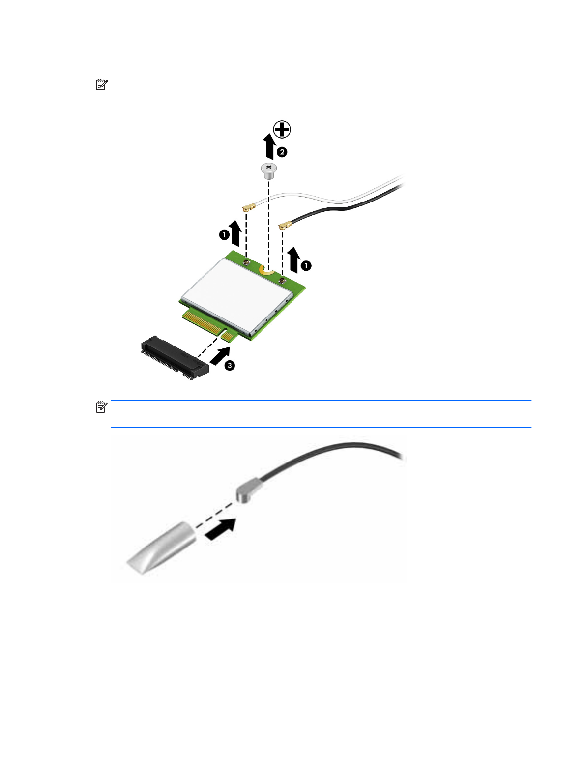
3. Remove the WLAN module by pulling the module away from the slot at an angle (3).
NOTE: WLAN modules are designed with a notch to prevent incorrect insertion.
NOTE: If the WLAN antennas are not connected to the terminals on the WLAN module, the protective
sleeves must be installed on the antenna connectors, as shown in the following illustration.
Reverse this procedure to install the WLAN module.
34 Chapter 5 Removal and replacement procedures for Customer Self-Repair parts
Page 45

WWAN module
The WLAN module and WWAN module are not interchangeable.
The WWAN module is available on select models only.
Description Spare part number
HP lt4120 LTE/EVDO/HSPA+ SnapdragonT X5 LTE Mobile Broadband Module 800870-001
Huawei MU736 HSPA+ with GPS M.2 (NGFF) 822828-001
Before removing the WWAN module, follow these steps:
1. Shut down the computer. If you are unsure whether the computer is o or in Hibernation, turn the
computer on, and then shut it down through the operating system.
2. Disconnect all external devices connected to the computer.
3. Disconnect the power from the computer by rst unplugging the power cord from the AC outlet, and
then unplugging the AC adapter from the computer.
4. Remove the bottom cover (see Bottom cover on page 26).
5. Remove the battery (see Battery on page 29).
Remove the WWAN module:
1. Position the computer upside-down.
2. Disconnect the WWAN antenna cables (1) from the terminals on the WWAN module.
NOTE: The red WWAN antenna cable is connected to the WWAN module “Main” terminal. The blue
WWAN antenna cable is connected to the WWAN module “Aux” terminal.
3. Remove the one Phillips PM2.5×3.0 screws (2) that secure the WWAN module to the computer. (The
edge of the module opposite the slot rises away from the computer.)
Component replacement procedures 35
Page 46

4. Remove the WWAN module (3) by pulling the module away from the slot at an angle.
NOTE: WWAN modules are designed with a notch to prevent incorrect insertion.
NOTE: If the WWAN antennas are not connected to the terminals on the WWAN module, the protective
sleeves must be installed on the antenna connectors, as shown in the following illustration.
Reverse this procedure to install the WWAN module.
36 Chapter 5 Removal and replacement procedures for Customer Self-Repair parts
Page 47

Keyboard
In this section, the rst table provides the main spare part number for the keyboards. The second table
provides the country codes.
Description Spare part number
Keyboard 836634-xx1
For use in country
or region
Belgium -A41 India -D61 Saudi Arabia -171
Brazil -201 Israel -BB1 Slovenia -BA1
Bulgaria -261 Italy -061 South Korea -AD1
Canada -DB1 Japan -291 Spain -071
Czech Republic
and Slovakia
Denmark -081 The Netherlands -B31 Switzerland -BG1
France -051 Northern Africa -FP1 Taiwan -AB1
Germany -041 Norway -091 Thailand -281
Greece -151 Portugal -131 Turkey -141
Hungary -211 Romania -271 United Kingdom -031
Iceland -DD1 Russia -251 United States -001
Spare part
number
-FL1 Latin America -161 Sweden and Finland -B71
For use in country
or region
Spare part
number
For use in country
or region
Spare part
number
Before removing the keyboard, follow these steps:
1. Shut down the computer. If you are unsure whether the computer is o or in Hibernation, turn the
computer on, and then shut it down through the operating system.
2. Disconnect all external devices connected to the computer.
3. Disconnect the power from the computer by rst unplugging the power cord from the AC outlet, and
then unplugging the AC adapter from the computer.
4. Remove the bottom cover (see Bottom cover on page 26).
5. Remove the battery (see Battery on page 29).
Remove the keyboard:
1. Remove the 2 Phillips PM2.5×5.0 screws that secure the keyboard to the computer (1).
NOTE: The screws are labeled with a keyboard symbol.
2. Position the computer upright with the front toward you.
3. Open the computer as far as possible.
Component replacement procedures 37
Page 48

4. Insert a screwdriver or similar thin tool into the hole beside the heat sink/fan assembly, and then press
on the back of the keyboard until it disengages from the computer (2).
NOTE: Cables connect the bottom of the keyboard to the system board. Make sure not to prematurely
pull the keyboard cables out of the system board connectors.
38 Chapter 5 Removal and replacement procedures for Customer Self-Repair parts
Page 49
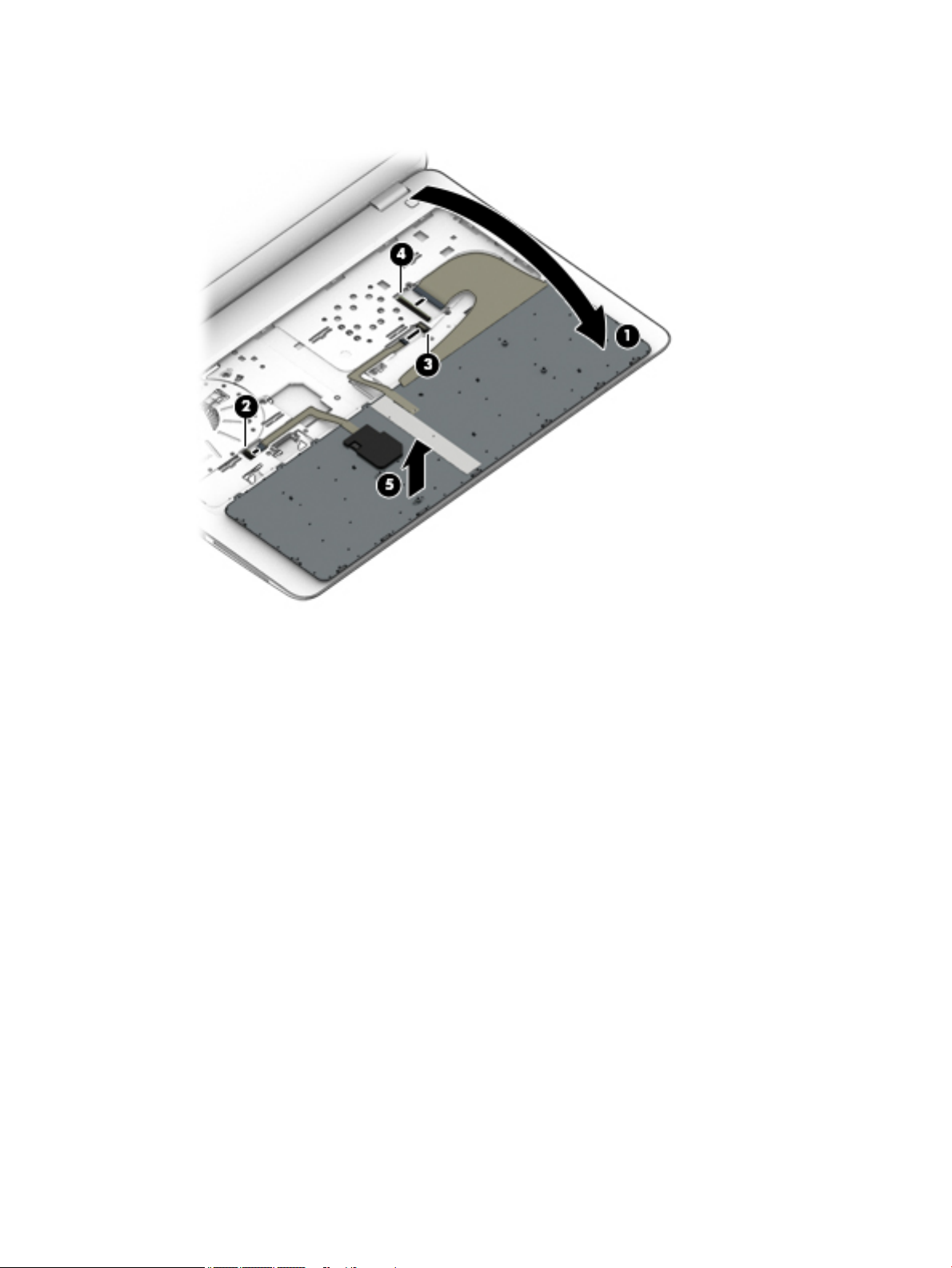
5. Rotate the top of the keyboard upward, and then place the keyboard on the palm rest (1). Remove the
keyboard backlight cable (2), pointing stick cable (3), and keyboard cable (4).
6. Remove the keyboard (5).
Reverse this procedure to install the keyboard.
Component replacement procedures 39
Page 50

6 Removal and replacement procedures for
Authorized Service Provider parts
This chapter provides removal and replacement procedures for Authorized Service Provider only parts.
CAUTION: Components described in this chapter should only be accessed by an authorized service provider.
Accessing these parts can damage the computer or void the warranty.
CAUTION: This computer does not have user-replaceable parts. Only HP authorized service providers should
perform the removal and replacement procedures described here. Accessing the internal part could damage
the computer or void the warranty.
Component replacement procedures
NOTE: Details about your computer, including model, serial number, product key, and length of warranty,
are on the service tag at the bottom of your computer. See Locating system information on page 13 for
details.
NOTE: HP continually improves and changes product parts. For complete and current information on
supported parts for your computer, go to http://partsurfer.hp.com, select your country or region, and then
follow the on-screen instructions.
There are as many as 45 screws that must be removed, replaced, and/or loosened when servicing Authorized
Service Provider only parts. Make special note of each screw size and location during removal
and replacement.
40 Chapter 6 Removal and replacement procedures for Authorized Service Provider parts
Page 51

RTC battery
Description Spare part number
RTC battery 665733-001
Before removing the RTC battery, follow these steps:
1. Shut down the computer. If you are unsure whether the computer is o or in Hibernation, turn the
2. Disconnect all external devices connected to the computer.
3. Disconnect the power from the computer by rst unplugging the power cord from the AC outlet, and
4. Remove the bottom cover (see Bottom cover on page 26).
5. Remove the battery (see Battery on page 29).
Remove the RTC battery:
1. Remove the RTC battery cable from the system board (1).
2. Lift the mylar cover (2).
3. Using a at tool, pry the battery out of the socket (3).
computer on, and then shut it down through the operating system.
then unplugging the AC adapter from the computer.
Reverse this procedure to install the RTC battery.
Component replacement procedures 41
Page 52

Internal base plate
Before removing the internal base plate, follow these steps:
1. Shut down the computer. If you are unsure whether the computer is o or in Hibernation, turn the
computer on, and then shut it down through the operating system.
2. Disconnect all external devices connected to the computer.
3. Disconnect the power from the computer by rst unplugging the power cord from the AC outlet, and
then unplugging the AC adapter from the computer.
4. Remove the bottom cover (see Bottom cover on page 26).
5. Remove the battery (see Battery on page 29).
Remove the internal base plate:
1. Remove 4 Phillips PM2.0x7.0 screws (1) and 6 PM2.5x2.5 screws (2).
42 Chapter 6 Removal and replacement procedures for Authorized Service Provider parts
Page 53

2. Remove 9 Phillips PM2.5x5.0 screws (1), and then remove the base plate from the computer (2).
Reverse this procedure to install the internal base plate.
Component replacement procedures 43
Page 54

Heat sink/fan assembly
NOTE: The heat sink/fan assembly spare part kit includes replacement thermal material.
Description Spare part number
Heat sink/thermal module with fans 821163-001
Before removing the heat sink/fan assembly, follow these steps:
1. Turn o the computer. If you are unsure whether the computer is o or in Hibernation, turn the
computer on, and then shut it down through the operating system.
2. Disconnect the power from the computer by unplugging the power cord from the computer.
3. Disconnect all external devices from the computer.
4. Bottom cover (see Bottom cover on page 26).
5. Remove the battery (see Battery on page 29).
6. Remove the internal base plate (see Internal base plate on page 42).
Remove the heat sink/fan assembly:
▲
Loosen the six captive screws on the fan and heat sink following the sequence stamped on the heat sink
(1), disconnect the fan cable (2), and then remove the heat sink/fan assembly from the system board
(3).
CAUTION: Take extreme care when removing the heat sink and fan assembly. The heatpipes between
the fans are very fragile and can be easily damaged and bent during removal.
NOTE: The thermal material must be thoroughly cleaned from the surfaces of the heat sink and the
system board components each time the heat sink is removed. Replacement thermal material is
included with the heat sink, processor, and system board spare part kits.
44 Chapter 6 Removal and replacement procedures for Authorized Service Provider parts
Page 55

Reverse this procedure to install the heat sink/fan assembly.
Component replacement procedures 45
Page 56

Power button board
Description Spare part number
Power button board assembly 821169-001
Before removing the power button board, follow these steps:
1. Shut down the computer. If you are unsure whether the computer is o or in Hibernation, turn the
computer on, and then shut it down through the operating system.
2. Disconnect all external devices connected to the computer.
3. Disconnect the power from the computer by rst unplugging the power cord from the AC outlet, and
then unplugging the AC adapter from the computer.
4. Remove the bottom cover (see Bottom cover on page 26).
5. Remove the battery (see Battery on page 29).
6. Remove the following components:
a. Keyboard (see Keyboard on page 37)
b. Internal base plate (Internal base plate on page 42)
Remove the power button board:
1. Disconnect the cable from the system board (1).
2. Remove the Phillips PM2.5×2.5 screw (2) that secures the power button board to the top cover.
3. Push the lever left (3).
4. Slide the power button board left from beneath the hinge (4).
Reverse this procedure to install the power button board.
46 Chapter 6 Removal and replacement procedures for Authorized Service Provider parts
Page 57

Touchpad button board
Description Spare part number
Touchpad button board 821171-001
Before removing the touchpad button board, follow these steps:
1. Shut down the computer. If you are unsure whether the computer is o or in Hibernation, turn the
computer on, and then shut it down through the operating system.
2. Disconnect all external devices connected to the computer.
3. Disconnect the power from the computer by rst unplugging the power cord from the AC outlet, and
then unplugging the AC adapter from the computer.
4. Remove the bottom cover (see Bottom cover on page 26).
5. Remove the battery (see Battery on page 29).
6. Remove the following components:
a. Keyboard (see Keyboard on page 37)
b. Internal base plate (Internal base plate on page 42)
Remove the touchpad button board:
1. Disconnect the cable from the touchpad to the smart card reader board (1), and then disconnect the NFC
antenna from the NFC module (2).
2. Lift the tape (3), and then remove the 2 Phillips PM2.5x2.5 screws (4) that secure the touchpad button
board to the top cover.
3. Lift the top of the touchpad button board up, and then pull it forward to remove it from the slot (5).
Reverse this procedure to install the touchpad board.
Component replacement procedures 47
Page 58
USB/audio board
Description Spare part number
USB/audio board 837846-001
Before removing the USB/audio board, follow these steps:
1. Shut down the computer. If you are unsure whether the computer is o or in Hibernation, turn the
computer on, and then shut it down through the operating system.
2. Disconnect all external devices connected to the computer.
3. Disconnect the power from the computer by rst unplugging the power cord from the AC outlet, and
then unplugging the AC adapter from the computer.
4. Remove the bottom cover (see Bottom cover on page 26).
5. Remove the battery (see Battery on page 29).
6. Remove the following components:
a. Keyboard (see Keyboard on page 37)
b. Internal base plate (Internal base plate on page 42)
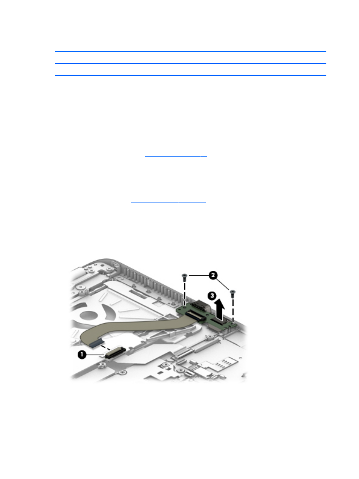
Remove the USB/audio board:
1. Disconnect the cable from the board (1).
2. Remove the 2 Phillips PM2.5×5.0 screws (2) that secure the USB/audio board to the computer.
3. Lift the board o the top cover (3).
Reverse this procedure to install the USB/audio board.
48 Chapter 6 Removal and replacement procedures for Authorized Service Provider parts
Page 59

System board
NOTE: All system board spare part kits include replacement thermal material.
Description Spare part number
System board with an AMD A8 Pro-8600B processor for use in models with the Windows Embedded
Standard operating system
System board with an AMD A8 Pro-8600B processor for use in models with the Windows 10 IoT Enterprise
operating system
827570-001
827570-601
Before removing the system board, follow these steps:
1. Shut down the computer. If you are unsure whether the computer is o or in Hibernation, turn the
computer on, and then shut it down through the operating system.
2. Disconnect all external devices connected to the computer.
3. Disconnect the power from the computer by rst unplugging the power cord from the AC outlet, and
then unplugging the AC adapter from the computer.
4. Remove the bottom cover (see Bottom cover on page 26).
5. Remove the battery (see Battery on page 29).
6. Remove the following components:
a. Keyboard (see Keyboard on page 37)
b. Internal base plate (see Internal base plate on page 42)
c. Power button board (see Power button board on page 46)
d. USB/audio board (see USB/audio board on page 48)
When replacing the system board, be sure to remove the following components from the defective system
board and install on the replacement system board:
●
Memory modules (see Memory modules on page 31)
●
WLAN/Bluetooth module (see WLAN/Bluetooth combo card on page 33)
●
WWAN module (see WWAN module on page 35)
●
SSD (see SSD on page 30)
●
Heat sink/ fan assembly (see Heat sink/fan assembly on page 44)
Remove the system board:
1. Disconnect the following cables from the system board:
(1) Speaker cable
(2) Display cable
(3) Webcam cable (select products only)
Component replacement procedures 49
Page 60

2. Remove the 2 Phillips PM2.5×5.0 screws (1) that secure the system board to the computer.
3. Lift the right side of the system board up at an angle (2).
4. Pull the system board up and toward the right to remove it from the computer (3).
Reverse this procedure to install the system board.
50 Chapter 6 Removal and replacement procedures for Authorized Service Provider parts
Page 61

Speaker assembly
Description Spare part number
Speaker assembly (includes cable) 821170-001
Before removing the speaker assembly, follow these steps:
1. Turn o the computer. If you are unsure whether the computer is o or in Hibernation, turn the
computer on, and then shut it down through the operating system.
2. Disconnect the power from the computer by unplugging the power cord from the computer.
3. Disconnect all external devices from the computer.
4. Remove the bottom cover (see Bottom cover on page 26).
5. Remove the battery (see Battery on page 29).
6. Remove the keyboard (see Keyboard on page 37).
7. Remove the heat sink/fan assembly (see Heat sink/fan assembly on page 44).
8. Remove the system board (see System board on page 49).
Remove the speaker assembly:
1. Remove the two Phillips PM2.5x2.5 screws that secure the speakers to the computer (1).
2. Remove the speaker (2) from the computer.
Reverse this procedure to install the speakers.
Component replacement procedures 51
Page 62

Display assembly
Before removing the display assembly, follow these steps:
1. Shut down the computer. If you are unsure whether the computer is o or in Hibernation, turn the
computer on, and then shut it down through the operating system.
2. Disconnect all external devices connected to the computer.
3. Disconnect the power from the computer by rst unplugging the power cord from the AC outlet, and
then unplugging the AC adapter from the computer.
4. Remove the bottom cover (see Bottom cover on page 26).
5. Remove the battery (see Battery on page 29).
6. Remove the following components:
a. WLAN module (see WLAN/Bluetooth combo card on page 33)
b. WWAN module (see WWAN module on page 35)
Remove the display assembly:
1. Position the computer upside down.
2. Disconnect the display cable from the system board.
3. Remove the WLAN antennas and WWAN antennas (if equipped) from the routing path along the base of
the computer.
4. Remove the 5 Phillips PM2.5×5.0 screws (1) from the display hinges.
5. Lift the display assembly straight up and remove it (2).
CAUTION: When installing the display assembly, be sure that the wireless antenna cables are routed
and arranged properly.
Failure to properly route the antennas can result in degradation of the computer's wireless performance.
52 Chapter 6 Removal and replacement procedures for Authorized Service Provider parts
Page 63
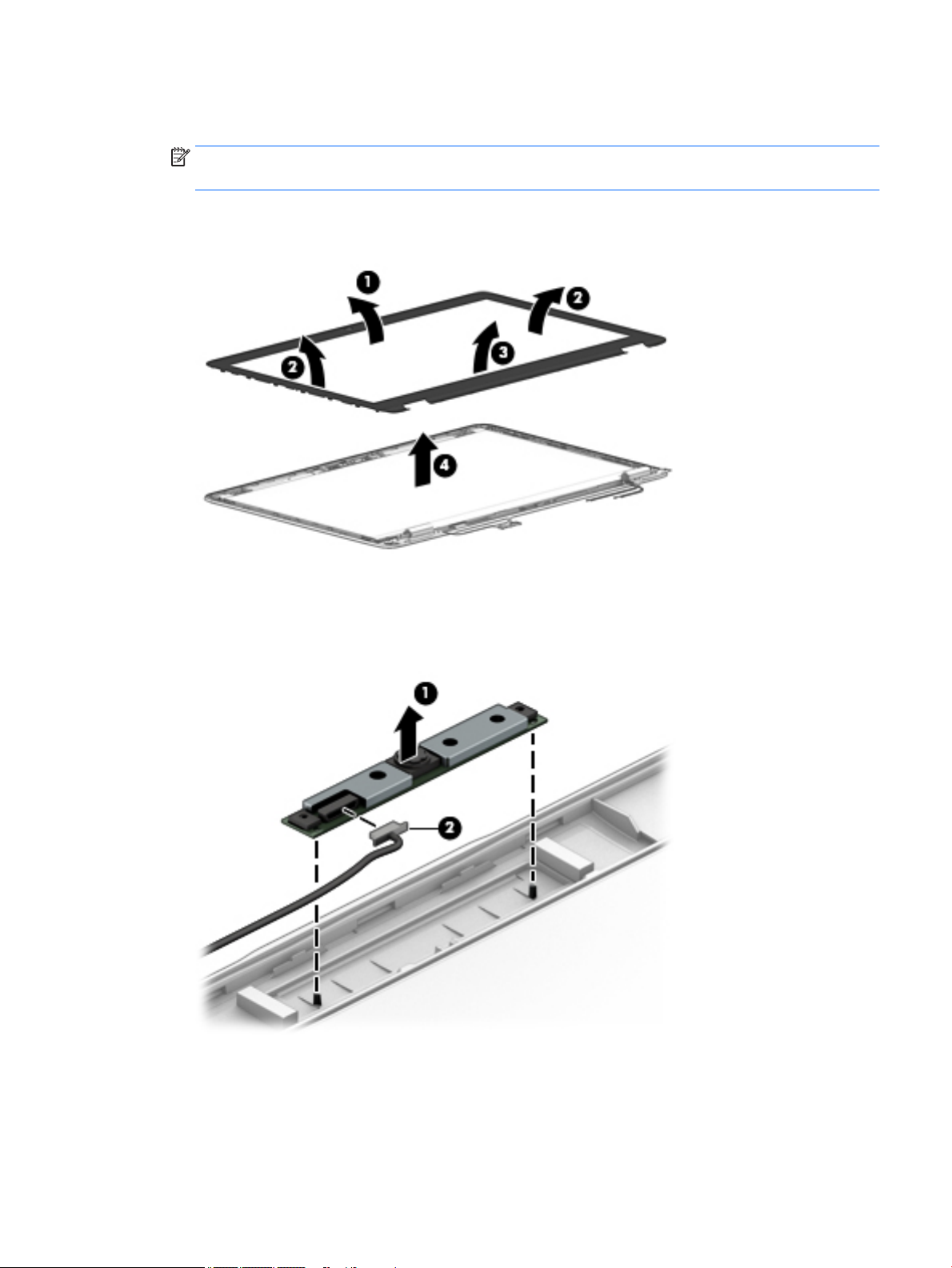
6. If you need to remove the display bezel, ex the top (1) of the bezel, the inside edges of the left and
right sides (2), and then the bottom (3) of the bezel until it disengages from the display enclosure.
NOTE: Make sure the hinges are not bent (see hinge position in following image) when you remove the
bezel.
7. Remove the display bezel (4).
The display bezel is available using spare part number 821197-001.
8. If it is necessary to replace the webcam or microphone module, gently pull the module away from the
double-sided tape on the display enclosure (1), and then disconnect the cable from the module (2).
The webcam module is available using spare part number 821676-001. The microphone module is
available using spare part number 821168-001.
Component replacement procedures 53
Page 64

9. If it is necessary to remove the display panel from the enclosure, remove the 4 Phillips PM2.0×3.0
screws that secure the panel to the display enclosure, and then lift the top of the panel upward.
The raw display panel is available using spare part number 823951-001.
10. Rotate the display panel all the way over (1), disconnect the display cable from the rear of the panel (2),
and then remove the display panel from the enclosure.
11. If it is necessary to replace the display hinges, remove the 1 Phillips PM2.0×3.0 screw (1) that secure the
hinge covers to the display enclosure, and then remove the hinge covers (2).
54 Chapter 6 Removal and replacement procedures for Authorized Service Provider parts
Page 65

12. Remove the 6 Phillips PM2.5x2.5 screws that secure the hinges to the display enclosure (3), and then
remove the display hinges from the display enclosure (4).
Display hinges are available in the Display Hinge Kit using spare part number 821166-001.
13. If it is necessary to replace the display/webcam cable, lift the display/webcam cable assembly (1) from
the routing (2) and disconnect the cable if needed (3).
The display cable is available in the Cable Kit using spare part number 821174-001.
Reverse this procedure to reassemble and install the display assembly.
Component replacement procedures 55
Page 66

Top cover
Before removing the top cover, follow these steps:
1. Shut down the computer. If you are unsure whether the computer is o or in Hibernation, turn the
2. Disconnect all external devices connected to the computer.
3. Disconnect the power from the computer by rst unplugging the power cord from the AC outlet, and
4. Remove all other components.
Reverse this procedure to install the top cover.
Description Spare part number
Top cover 821173-001
computer on, and then shut it down through the operating system.
then unplugging the AC adapter from the computer.
56 Chapter 6 Removal and replacement procedures for Authorized Service Provider parts
Page 67

7 Computer Setup (BIOS) and MultiBoot
Using Computer Setup
Computer Setup, or Basic Input/Output System (BIOS), controls communication between all the input and
output devices on the system (such as disk drives, display, keyboard, mouse, and printer). Computer Setup
includes settings for the types of devices installed, the startup sequence of the computer, and the amount of
system and extended memory.
NOTE: Use extreme care when making changes in Computer Setup. Errors can prevent the computer from
operating properly.
Starting Computer Setup
NOTE: An external keyboard or mouse connected to a USB port can be used with Computer Setup only if USB
legacy support is enabled.
To start Computer Setup, follow these steps:
1. Turn on or restart the computer, and then press esc while the “Press the ESC key for Startup Menu”
message is displayed at the bottom of the screen.
2. Press f10 to enter Computer Setup.
Navigating and selecting in Computer Setup
To navigate and select in Computer Setup, follow these steps:
1. Turn on or restart the computer, and then press esc while the “Press the ESC key for Startup Menu”
message is displayed at the bottom of the screen.
NOTE: You can use either a pointing device (TouchPad, pointing stick, or USB mouse) or the keyboard
to navigate and make selections in Computer Setup.
2. Press f10 to enter Computer Setup.
●
To select a menu or a menu item, use the tab key and the keyboard arrow keys and then press
enter, or use a pointing device to click the item.
●
To scroll up and down, click the up arrow or the down arrow in the upper-right corner of the screen,
or use the up arrow key or the down arrow key on the keyboard.
●
To close open dialog boxes and return to the main Computer Setup screen, press esc, and then
follow the on-screen instructions.
To exit Computer Setup menus, choose one of the following methods:
●
To exit Computer Setup menus without saving your changes:
Click the Exit icon in the lower-right corner of the screen, and then follow the on-screen instructions.
– or –
Use the arrow keys to select Main > Ignore Changes and Exit, and then press enter.
●
To save your changes and exit Computer Setup menus:
Using Computer Setup 57
Page 68

Click the Save icon in the lower-right corner of the screen, and then follow the on-screen instructions.
– or –
Use the arrow keys to select Main > Save Changes and Exit, and then press enter.
Your changes go into eect when the computer restarts.
Restoring factory settings in Computer Setup
NOTE: Restoring defaults will not change the hard drive mode.
To return all settings in Computer Setup to the values that were set at the factory, follow these steps:
1. Turn on or restart the computer, and then press esc while the “Press the ESC key for Startup Menu”
message is displayed at the bottom of the screen.
2. Press f10 to enter Computer Setup.
3. Use a pointing device or the arrow keys to select Main > Restore Defaults.
4. Follow the on-screen instructions.
5. To save your changes and exit, click the Save icon in the lower-right corner of the screen, and then
follow the on-screen instructions.
– or –
Use the arrow keys to select Main > Save Changes and Exit, and then press enter.
Your changes go into eect when the computer restarts.
NOTE: Your password settings and security settings are not changed when you restore the factory settings.
Updating the BIOS
Updated versions of the BIOS may be available on the HP website.
Some download packages contain a le named Readme.txt, which contains information regarding installing
and troubleshooting the le.
Determining the BIOS version
To determine whether available BIOS updates contain later BIOS versions than those currently installed on the
computer, you need to know the version of the system BIOS currently installed.
BIOS version information (also known as ROM date and System BIOS) can be revealed by pressing fn+esc (if
you are already in Windows) or by using Computer Setup.
1. Start Computer Setup.
2. Use a pointing device or the arrow keys to select Main > System Information.
3. To exit Computer Setup without saving your changes, click the Exit icon in the lower-right corner of the
screen, and then follow the on-screen instructions.
– or –
Use the arrow keys to select Main > Ignore Changes and Exit, and then press enter.
58 Chapter 7 Computer Setup (BIOS) and MultiBoot
Page 69

Downloading a BIOS update
CAUTION: To reduce the risk of damage to the computer or an unsuccessful installation, download and
install a BIOS update only when the computer is connected to reliable external power using the AC adapter. Do
not download or install a BIOS update while the computer is running on battery power, docked in an optional
docking device, or connected to an optional power source. During the download and installation, follow these
instructions:
Do not disconnect power on the computer by unplugging the power cord from the AC outlet.
Do not shut down the computer or initiate Sleep.
Do not insert, remove, connect, or disconnect any device, cable, or cord.
1. To access HP Support, go to http://www.hp.com/support, and select your country. Select Drivers &
Downloads, and then follow the on-screen instructions to access BIOS downloads.
2. At the BIOS download area, follow these steps:
a. Identify the most recent BIOS update and compare it to the BIOS version currently installed on your
computer. Make a note of the date, name, or other identier. You may need this information to
locate the update later, after it has been downloaded to your hard drive.
b. Follow the on-screen instructions to download your selection to the hard drive.
If the update is more recent than your BIOS, make a note of the path to the location on your hard
drive where the BIOS update is downloaded. You will need to access this path when you are ready
to install the update.
NOTE: If you connect your computer to a network, consult the network administrator before installing
any software updates, especially system BIOS updates.
BIOS installation procedures vary. Follow any instructions that are revealed on the screen after the download
is complete. If no instructions are revealed, follow these steps:
1. Select Start > Computer.
2. Click your hard drive designation. The hard drive designation is typically Local Disk (C:).
3. Using the hard drive path you recorded earlier, open the folder on your hard drive that contains the
update.
4. Double-click the le that has an .exe extension (for example, lename.exe).
The BIOS installation begins.
5. Complete the installation by following the on-screen instructions.
NOTE: After a message on the screen reports a successful installation, you can delete the downloaded le
from your hard drive.
Using MultiBoot
About the boot device order
As the computer starts, the system attempts to boot from enabled devices. The MultiBoot utility, which is
enabled at the factory, controls the order in which the system selects a boot device. Boot devices can include
optical drives, diskette drives, a network interface card (NIC), hard drives, and USB devices. Boot devices
contain bootable media or les that the computer needs to start and operate properly.
NOTE: Some boot devices must be enabled in Computer Setup before they can be included in the boot order.
Using MultiBoot 59
Page 70

You can change the order in which the computer searches for a boot device by changing the boot order in
Computer Setup. You can also press esc while the “Press the ESC key for Startup Menu” message is displayed
at the bottom of the screen, and then press f9. Pressing f9 displays a menu that shows the current boot
devices and allows you to select a boot device. Or, you can use MultiBoot Express to set the computer to
prompt you for a boot location each time the computer turns on or restarts.
Choosing MultiBoot preferences
You can use MultiBoot in the following ways:
●
To set a new boot order that the computer uses each time it is turned on, by changing the boot order in
Computer Setup.
●
To dynamically choose the boot device, by pressing esc while the “Press the ESC key for Startup Menu”
message is displayed at the bottom of the screen, and then pressing f9 to enter the Boot Device Options
menu.
●
To use MultiBoot Express to set variable boot orders. This feature prompts you for a boot device each
time the computer is turned on or restarted.
Setting a new boot order in Computer Setup
To start Computer Setup and set a boot device order that the computer uses each time it is turned on or
restarted, follow these steps:
1. Turn on or restart the computer, and then press esc while the “Press the ESC key for Startup Menu”
message is displayed at the bottom of the screen.
2. Press f10 to enter Computer Setup.
3. Use a pointing device or the arrow keys to select the Legacy Boot Order list, and then press enter.
4. To move the device up in the boot order, use a pointing device to click the up arrow, or press the + key.
– or –
To move the device down in the boot order, use a pointing device to click the down arrow, or press the -
key.
5. To save your changes and exit Computer Setup, click the Save icon in the lower-left corner of the screen,
and then follow the on-screen instructions.
– or –
Use the arrow keys to select Main > Save Changes and Exit, and then press enter.
Dynamically choosing a boot device using the f9 prompt
To dynamically choose a boot device for the current startup sequence, follow these steps:
1. Open the Select Boot Device menu by turning on or restarting the computer, and then pressing esc while
the “Press the ESC key for Startup Menu” message is displayed at the bottom of the screen.
2. Press f9.
3. Use a pointing device or the arrow keys to select a boot device, then press enter.
60 Chapter 7 Computer Setup (BIOS) and MultiBoot
Page 71

Setting a MultiBoot Express prompt
To start Computer Setup and set the computer to display the MultiBoot startup location menu each time the
computer is started or restarted, follow these steps:
1. Turn on or restart the computer, and then press esc while the “Press the ESC key for Startup Menu”
message is displayed at the bottom of the screen.
2. Press f10 to enter Computer Setup.
3. Use a pointing device or the arrow keys to select System Conguration > Boot Options, and then press
enter.
4. In the MultiBoot Express Popup Delay (Sec) eld, enter the length of time in seconds that you want the
computer to display the startup location menu before it defaults to the current MultiBoot setting. (When
0 is selected, the Express Boot startup location menu is not displayed.)
5. To save your changes and exit Computer Setup, click the Save icon in the lower-left corner of the screen,
and then follow the on-screen instructions.
– or –
Use the arrow keys to select Main > Save Changes and Exit, and then press enter.
Your changes go into eect when the computer restarts.
Entering MultiBoot Express preferences
When the Express Boot menu is displayed during startup, you have the following choices:
●
To specify a boot device from the Express Boot menu, select your preference within the allotted time,
and then press enter.
●
To prevent the computer from defaulting to the current MultiBoot setting, press any key before the
allotted time expires. The computer will not start until you select a boot device and press enter.
●
To allow the computer to start according to the current MultiBoot settings, wait for the allotted time to
expire.
Using HP Sure Start (select models only)
Select computer models are congured with HP Sure Start, a technology that continuously monitors the
computer's BIOS for attacks or corruption. If the BIOS becomes corrupted or is attacked, HP Sure Start
automatically restores the BIOS to its previously safe state, without user intervention.
HP Sure Start is congured and already enabled so that most users can use the HP Sure Start default
conguration. The default conguration can be customized by advanced users.
To access the latest documentation on HP Sure Start, go to http://www.hp.com/support, and select your
country. Select Drivers & Downloads, and then follow the on-screen instructions.
Using HP Sure Start (select models only) 61
Page 72

8 Using HP PC Hardware Diagnostics (UEFI)
HP PC Hardware Diagnostics is a Unied Extensible Firmware Interface (UEFI) that allows you to run diagnostic
tests to determine whether the computer hardware is functioning properly. The tool runs outside the
operating system so that it can isolate hardware failures from issues that are caused by the operating system
or other software components.
When HP PC Hardware Diagnostics (UEFI) detects a failure that requires hardware replacement, a 24-digit
Failure ID is generated. This ID can then be provided to support to help determine how to correct the problem.
To start HP PC Hardware Diagnostics (UEFI), follow these steps:
1. Turn on or restart the computer, and quickly press esc
2. Press F2.
The BIOS searches three places for the diagnostic tools, in the following order:
a. Connected USB drive
NOTE: To download the HP PC Hardware Diagnostics (UEFI) tool to a USB drive, see Downloading
HP PC Hardware Diagnostics (UEFI) to a USB device on page 62.
b. Hard drive (not applicable)
c. BIOS
3. When the diagnostic tool opens, select the type of diagnostic test you want to run, and then follow the
on-screen instructions.
NOTE: If you need to stop a diagnostic test, press esc.
Downloading HP PC Hardware Diagnostics (UEFI) to a USB device
NOTE: The HP PC Hardware Diagnostics (UEFI) download instructions are provided in English only, and you
must use a Windows computer to download and create the HP UEFI support environment because only .exe
les are oered.
There are two options to download HP PC Hardward Diagnostics to USB device.
Download the latest UEFI version
1. Go to http://www.hp.com/go/techcenter/pcdiags. The HP PC Diagnostics home page is displayed.
2. In the HP PC Hardware Diagnostics section, click the Dowload link, and then select Run.
Download any version of UEFI for a specic product
1. Go to http://www.hp.com/support, and then select your country. The HP Support page is displayed. .
2. Click Drivers & Downloads.
3. Use the categories listed to nd your product.
– or –
Click Find Now to let HP automatically detect your product.
62 Chapter 8 Using HP PC Hardware Diagnostics (UEFI)
Page 73

4. Select your computer, and then select your operating system.
5. In the Diagnostic section, follow the on-screen instructions to select and download the UEFI version you
want.
Downloading HP PC Hardware Diagnostics (UEFI) to a USB device 63
Page 74

9 Device management
The HP mt42 Mobile Thin Client includes a license for HP Device Manager and has a Device Manager agent preinstalled. HP Device Manager is an optimized management tool used to manage the full life cycle of HP
products to include Discover, Asset Management, Deployment and Conguration. For more information on HP
Device Manager, please visit www.hp.com/go/hpdm.
If you wish to manage the HP mt42 Mobile Thin Client with other management tools such as Microsoft SCCM
or LANDesk, go to www.hp.com/go/clientmanagement for more information.
64 Chapter 9 Device management
Page 75

10 Diagnostics and Troubleshooting
LEDs
LED Status
Power LED O When the unit is plugged into the wall socket and the Power LED is o, the unit is powered o.
However, the network can trigger a Wake On LAN event in order to perform management functions.
Power LED On Displays during boot sequence and while the unit is on. During boot sequence, hardware initialization is
processed and startup tests are performed on the following:
●
Processor initialization
●
Memory detection and initialization
●
Video detection and initialization
NOTE: If one of the tests fails, the unit will simply stop, but the LED will stay on. If the video test fails,
the unit beeps. There are no messages sent to video for any of these failed tests.
NOTE: After the video is initialized, anything that fails will have an error message.
NOTE: RJ-45 LEDs – Blinking green indicates network activity, and amber indicates a 100MB speed connection.
IDE LED is O When the unit is powered on and the ash activity light is o, then there is no access to the system
ash.
IDE LED blinks white Indicates the system is accessing the internal IDE ash.
Wake-on LAN
Wake-on LAN (WOL) allows a computer to be turned on or resumed from sleep or hibernation state by a
network message. You can enable or disable WOL in Computer Setup using the S5 Maximum Power Savings
setting.
To enable or disable WOL:
1. Turn on or restart the computer.
2. Press either Esc or F10 while the “Press the ESC key for Startup Menu” message is displayed at the
bottom of the screen.
NOTE: If you do not press Esc or F10 at the appropriate time, you must restart the computer and again
press Esc or F10 when the monitor light turns green to access the utility.
3. If you pressed Esc, press F10 to enter Computer Setup.
4. Navigate to Advanced > Built-in Device Options.
5. Under Wake-on LAN, select the appropriate WOL setting.
6. Press F10 to accept any changes.
7. Select Main > Save Changes and Exit.
LEDs 65
Page 76

Power-On Sequence
At power-on, the ash boot block code initializes the hardware to a known state, then performs basic poweron diagnostic tests to determine the integrity of the hardware. Initialization performs the following functions:
1. Initializes CPU and memory controller.
2. Initializes and congures all PCI devices.
3. Initializes VGA software.
4. Initializes the video to a known state.
5. Initializes USB devices to a known state.
6. Performs power-on diagnostics. For more information, see “Power-On Diagnostic Tests”.
7. The unit boots the operating system.
Power-On Diagnostic Tests
The Power-on diagnostics performs basic integrity tests of the hardware to determine its functionality and
conguration. If a diagnostic test fails during hardware initialization the unit simply stops. There are no
messages sent to video.
NOTE: You may try to restart the unit and run through the diagnostic tests a second time to conrm the rst
shutdown.
The following table lists the tests that are performed on the unit.
Test Description
Boot Block Checksum Tests boot block code for proper checksum value
DRAM Simple write/read pattern test of the rst 640k of memory
Serial Port Tests the serial port using simple port verication test to determine if ports are present
Timer Tests timer interrupt by using polling method
RTC CMOS battery Tests integrity of RTC CMOS battery
NAND ash device Tests for proper NAND ash device ID present
Troubleshooting
Basic Troubleshooting
If the computer is experiencing operating problems or will not power on, review the following items.
10-1 Power-On Troubleshooting
Table
Issue Procedures
The computer unit is experiencing operating
problems.
Ensure that the following connectors are securely plugged into the computer:
Power connector, keyboard, mouse, network RJ-45 connector, monitor
66 Chapter 10 Diagnostics and Troubleshooting
Page 77

Table 10-1 Power-On Troubleshooting (continued)
The computer does not power on. 1. Verify that the power supply is good by installing it on a known working unit
and testing it. If the power supply does not work on the test unit, replace the
power supply.
2. If the unit does not work properly with the replaced power supply, have the
unit serviced.
The computer powers on and displays a splash
screen, but does not connect to the server.
No link or activity on the network RJ-45 LEDs or
the LEDs do not illuminate blinking green after
powering on the computer. (The network LEDs
are located inside the RJ-45 connector on the
top, rear panel of the computer. Indicator lights
are visible when the connector is installed.)
A newly connected unknown USB peripheral
does not respond or USB peripherals connected
prior to the newly connected USB peripheral will
not complete their device actions.
1. Verify that the network is operating and the network cable is working
properly.
2. Verify that the unit is communicating with the server by having the System
Administrator ping the unit from the server:
●
If the computer pings back, then the signal was accepted and the unit is
working. This indicates a conguration issue.
●
If the computer does not ping back and the computer does not connect
to the server, re-image the unit.
1. Verify that the network is not down.
2. Make sure the RJ-45 cable is good by installing the RJ-45 cable onto a known
working device—if a network signal is detected then the cable is good.
3. Verify the power supply is good by replacing the power cable to the unit with
a known working power supply cable and testing it.
4. If network LED's still do not light and you know the power supply is good,
then re-image the unit.
5. If network LED’s still do not light, run the IP conguration procedure.
6. If network LED’s still do not light, have the unit serviced.
An unknown USB peripheral may be connected and disconnected to a running
platform as long as you do not reboot the system. If problems occur, disconnect
the unknown USB peripheral and reboot the platform.
Conguring a PXE Server
NOTE: All PXE software is supported by authorized service providers on a warranty or service contract basis.
Customers that call the HP Customer Service Center with PXE issues and questions should be referred to their
PXE provider for assistance.
Additionally, refer to the following:
– For Windows 2008 R2: http://support.microsoft.com/kb/891275
– For Windows 2012: http://technet.microsoft.com/en-us/library/cc766320(WS.10).aspx
The services listed below must be running, and they may be running on dierent servers:
1. Domain Name Service (DNS)
2. Remote Installation Services (RIS)
NOTE: Active Directory DHCP is not required, but is recommended.
Conguring a PXE Server 67
Page 78

11 Restoring the Flash Image
System Requirements
To create a recovery device for the purpose of reashing or restoring the software image on the ROM, you will
need the following:
●
A personal computer running Microsoft Windows 7.
●
One or more HP mt42 Mobile Thin Clients
●
8-GB or larger USB ash device for Microsoft Windows Embedded Standard 7 (WES 7) (if using the USB
format).
This restore method will not work with all USB ash devices. USB ash devices with multiple
partitions generally do not support this restore method. The range of USB ash devices available on the
market is constantly changing. Not all USB ash devices have been tested with the HP Thin Client
Imaging Tool.
Before using the utility, you must download the appropriate image from http://www.hp.com.
Getting Started
There are two deployment options supported by this utility. You can choose to do one or more of the
following using your personal computer:"
●
Create a bootable ash image on a USB ash device.
●
Unbundle the image to a directory for use in a custom deployment scenario or PXE image.
Download and run the Package-for-the-Web deliverable (an .exe le) that contains the original factory image
for the computer. The HP Thin Client Imaging Tool (CRStart.exe) runs automatically.
Choose the USB deployment option.
During the restore process, the computer ash drive will be reformatted and all data on it will be erased
before the system image is copied to it. To prevent loss of data, be sure that you have saved any usercreated data from the ash drive. During the rst restart of the computer following the restore process,
it may take approximately 15 minutes to unbundle the software before the Windows Desktop is
displayed.
Formatting a USB Flash Drive
CAUTION: To prevent loss of data, be sure that you have saved any user-created data from the USB drive to
another drive.
1. Connect your USB ash device (drive key) to your personal computer. Ensure that only one USB ash
device is connected to the system.
2. Click USB Format.
68 Chapter 11 Restoring the Flash Image
Page 79

3. Select the USB drive from the list, using the up and down arrows to display the correct drive letter. (If the
USB drive does not appear in the list, click Update Drives, then scroll through the list again.)
During the next step, the USB drive will be reformatted and all data on it will be erased before the
bootable image is copied to it. To prevent loss of data, be sure that you have saved any data from the
USB drive to another drive.
4. Click Format. Connect the bootable USB ash device to the computer. Only one bootable USB device may
be attached to the computer during this process.
NOTE: Do not use USB 3.0 devices.
5. Restart the computer.
6. When prompted Do you want to continue? [Y/N] click Y to begin the image restore process on the
computer.
Unpacking the Image and Tools for Deployment
▲
Click Deployment.
The components that comprise the recovery image (DSKIMG.BIN) are unbundled.
When this process is complete, the four most important les include: IBRPE.EXE (the image restoration
utility), FLASH.IBR (the OS image), the ReadMe.TXT le, and boot.wim (the pre-install environment).
Deploying with PXE
1. Ensure that IBRPE.EXE and FLASH.IBR le exist.
2. Add the following command to execute IBRPE in WinPE environment: [full path]\IBRPE.EXE
[full path]\FLASH.IBR HD0
To view the IBR command line options: At the command prompt, type IBR.EXE /? and press Enter.
See your documentation if using a dierent PXE server, such as Altiris Deployment Solution.
Unpacking the Image and Tools for Deployment 69
Page 80

12 Adding an Image Restore Tool
1. Ensure that the boot order is set to use the Network as the rst boot device.
2. Ensure that IBR.exe (Image Restore) and Flash.dd are stored in the same directory on the server. (e.g.,
c:\program files\altiris\express\deployment server\images)
3. From the Altiris Deployment Server Console, click File > New > Job .
4. Enter a unique name for the job that you will use to deploy the original computer image.
5. Click the name of the new job.
6. Near the upper right side of the screen, click Add.
7. Select Run Script from the menu.
8. Type [full path]images\ibr\exe-y\images\ash.xx hd0
9. Under In which OS would you like to run this script? Click DOS.
10. Click Finish.
11. You can now drag and drop the job onto the appropriate machine(s) or schedule it to run later,
depending on your needs. Refer to the documentation for Altiris Deployment Solution
(http://www.altiris.com/support/documentation) for more detailed information.
70 Chapter 12 Adding an Image Restore Tool
Page 81

13 Power cord set requirements
The wide-range input feature of the computer permits it to operate from any line voltage from 100 to 120
volts AC, or from 220 to 240 volts AC.
The 3-conductor power cord set included with the computer meets the requirements for use in the country or
region where the equipment is purchased.
Power cord sets for use in other countries and regions must meet the requirements of the country or region
where the computer is used.
Requirements for all countries
The following requirements are applicable to all countries and regions:
●
The length of the power cord set must be at least 1.0 m (3.3 ft) and no more than 2.0 m (6.5 ft).
●
All power cord sets must be approved by an acceptable accredited agency responsible for evaluation in
the country or region where the power cord set will be used.
●
The power cord sets must have a minimum current capacity of 10 amps and a nominal voltage rating of
125 or 250 V AC, as required by the power system of each country or region.
●
The appliance coupler must meet the mechanical conguration of an EN 60 320/IEC 320 Standard Sheet
C13 connector for mating with the appliance inlet on the back of the computer.
Requirements for specic countries and regions
Country/region Accredited agency Applicable note number
Australia EANSW 1
Austria OVE 1
Belgium CEBC 1
Canada CSA 2
Denmark DEMKO 1
Finland FIMKO 1
France UTE 1
Germany VDE 1
Italy IMQ 1
Japan METI 3
The Netherlands KEMA 1
Norway NEMKO 1
The People's Republic of China COC 5
South Korea EK 4
Requirements for all countries 71
Page 82

Country/region Accredited agency Applicable note number
Sweden SEMKO 1
Switzerland SEV 1
Taiwan BSMI 4
The United Kingdom BSI 1
The United States UL 2
1. The exible cord must be Type HO5VV-F, 3-conductor, 1.0-mm² conductor size. Power cord set ttings (appliance coupler
and wall plug) must bear the certication mark of the agency responsible for evaluation in the country or region where it will be
used.
2. The exible cord must be Type SPT-3 or equivalent, No. 18 AWG, 3-conductor. The wall plug must be a two-pole grounding type
with a NEMA 5-15P (15 A, 125 V) or NEMA 6-15P (15 A, 250 V) conguration.
3. The appliance coupler, exible cord, and wall plug must bear a “T” mark and registration number in accordance with the Japanese
Dentori Law. The exible cord must be Type VCT or VCTF, 3-conductor, 1.00-mm² conductor size. The wall plug must be a twopole grounding type with a Japanese Industrial Standard C8303 (7 A, 125 V) conguration.
4. The exible cord must be Type RVV, 3-conductor, 0.75-mm² conductor size. Power cord set ttings (appliance coupler and wall
plug) must bear the certication mark of the agency responsible for evaluation in the country or region where it will be used.
5. The exible cord must be Type VCTF, 3-conductor, 0.75-mm² conductor size. Power cord set ttings (appliance coupler and wall
plug) must bear the certication mark of the agency responsible for evaluation in the country or region where it will be used.
72 Chapter 13 Power cord set requirements
Page 83

14 Statement of memory volatility
The purpose of this chapter is to provide general information regarding nonvolatile memory in HP Business
PCs. This chapter also provides general instructions for restoring nonvolatile memory that can contain
personal data after the system has been powered o and the hard drive has been removed.
HP Business PC products that use Intel®-based or AMD®-based system boards contain volatile DDR memory.
The amount of nonvolatile memory present in the system depends upon the system conguration. Intelbased and AMD-based system boards contain nonvolatile memory subcomponents as originally shipped from
HP, assuming that no subsequent modications have been made to the system and assuming that no
applications, features, or functionality have been added to or installed on the system.
Following system shutdown and removal of all power sources from an HP Business PC system, personal data
can remain on volatile system memory (DIMMs) for a nite period of time and will also remain in nonvolatile
memory. Use the steps below to remove personal data from the PC, including the nonvolatile memory found
in Intel-based and AMD-based system boards.
1. Follow steps (a) through (j) below to restore the nonvolatile memory that can contain personal data.
Restoring or reprogramming nonvolatile memory that does not store personal data is neither necessary
nor recommended.
a. Turn on or restart the computer, and then press esc while the “Press the ESC key for Startup Menu”
message is displayed at the bottom of the screen.
NOTE: If the system has a BIOS administrator password, enter the password at the prompt.
b. Select Main, select Restore Defaults, and then select Yes to load defaults.
c. Select the Security menu, select Restore Security Level Defaults, and then select Yes to restore
security level defaults.
d. If an asset or ownership tag is set, select the Security menu and scroll down to the Utilities menu.
Select System IDs, and then select Asset Tracking Number. Clear the tag, and then make the
selection to return to the prior menu.
e. If a DriveLock password is set, select the Security menu, and scroll down to Hard Drive Tools
under the Utilities menu. Select Hard Drive Tools, select DriveLock, then uncheck the checkbox
for DriveLock password on restart. Select OK to proceed.
f. If an Automatic DriveLock password is set, select the Security menu, scroll down to Hard Drive
Tools under the Utilities menu. Select Hard Drive Tools, scroll down to Automatic DriveLock, then
select the desired hard drive and disable protection. At the automatic drive lock warning screen,
select Yes to continue. Repeat this procedure if more than one hard drive has an Automatic
DriveLock password.
g. Select the Main menu, and then select Reset BIOS Security to factory default. Click Yes at the
warning message.
h. Select the Main menu, select Save Changes and Exit, select Yes to save changes and exit, and then
select Shutdown.
73
Page 84

i. Reboot the system. If the system has a Trusted Platform Module (TPM) and/or ngerprint reader,
one or two prompts will appear—one to clear the TPM and the other to Reset Fingerprint Sensor;
press or tap F1 to accept or F2 to reject.
j. Remove all power and system batteries for at least 24 hours.
2. Complete one of the following:
●
Remove and retain the storage drive.
– or –
●
Clear the drive contents by using a third party utility designed to erase data from an SSD.
– or –
●
Clear the contents of the drive by using the following BIOS Setup Secure Erase command option
steps:
IMPORTANT: If you clear data using Secure Erase, it cannot be recovered.
a. Turn on or restart the computer, and then press esc while the “Press the ESC key for Startup Menu”
message is displayed at the bottom of the screen.
b. Select the Security menu and scroll down to the Utilities menu.
c. Select Hard Drive Tools.
d. Under Utilities, select Secure Erase, select the hard drive storing the data you want to clear, and
then follow the on-screen instructions to continue.
– or –
●
Clear the contents of the drive by using the following Disk Sanitizer command steps:
IMPORTANT: If you clear data using Disk Sanitizer, it cannot be recovered.
NOTE: The amount of time it takes for Disk Sanitizer to run can take several hours. Plug the computer
into an AC outlet before starting.
a. Turn on or restart the computer, and then press esc while the “Press the ESC key for Startup Menu”
message is displayed at the bottom of the screen.
b. Select the Security menu and scroll down to the Utilities menu.
c. Select Hard Drive Tools.
d. Under Utilities, select Disk Sanitizer, select the hard drive storing the data you want to clear, and
then follow the on-screen instructions to continue.
74 Chapter 14 Statement of memory volatility
Page 85

Nonvolatile memory usage
Nonvolatile
Memory Type
HP Sure Start ash
(select models
only)
Real Time Clock
(RTC) battery
backed-up CMOS
conguration
memory
Amount (Size) Does this
memory
store
customer
data?
2 MBytes No Yes Provides
256 Bytes No Yes Stores system
Does this
memory
retain data
when power
is removed?
What is the
purpose of this
memory?
protected
backup of
critical System
BIOS code, EC
rmware, and
critical PC
conguration
data for select
platforms that
support HP
Sure Start.
For more
information,
see Using HP
Sure Start
(select models
only)
on page 78.
date and time
and noncritical
data.
How is data input into this
memory?
Data cannot be written to this
device via the host processor.
The content is managed
solely by the HP Sure Start
Embedded Controller.
RTC battery backed-up CMOS
is programmed using the
Computer Setup (BIOS), or
changing the Microsoft
Windows date & time.
How is this memory
write-protected?
This memory is protected
by the HP Sure Start
Embedded Controller.
This memory is not writeprotected.
Controller (NIC)
EEPROM
DIMM Serial
Presence Detect
(SPD)
conguration data
System BIOS 4 MBytes to 5
64 KBytes (not
customer
accessible)
256 Bytes per
memory
module, 128
Bytes
programmable
(not customer
accessible)
MBytes
No Yes Stores NIC
conguration
and NIC
rmware.
No Yes Stores memory
module
information.
Yes Yes Stores system
BIOS code and
PC
conguration
data.
NIC EEPROM is programmed
using a utility from the NIC
vendor that can be run from
DOS.
DIMM SPD is programmed by
the memory vendor.
System BIOS code is
programmed at the factory.
Code is updated when the
system BIOS is updated.
Conguration data and
settings are input using the
Computer Setup (BIOS) or a
custom utility.
A utility is required to
write data to this memory
and is available from the
NIC vendor. Writing data
to this ROM in an
inappropriate manner will
render the NIC nonfunctional.
Data cannot be written to
this memory when the
module is installed in a
PC. The specic writeprotection method varies
by memory vendor.
NOTE: Writing data to
this ROM in an
inappropriate manner can
render the PC nonfunctional.
A utility is required for
writing data to this
memory and is available
on the HP website; go to
http://www.hp.com/
support, and select your
country. Select Drivers &
Nonvolatile memory usage 75
Page 86

Nonvolatile
Memory Type
Amount (Size) Does this
memory
store
customer
data?
Does this
memory
retain data
when power
is removed?
What is the
purpose of this
memory?
How is data input into this
memory?
How is this memory
write-protected?
Downloads, and then
follow the on-screen
instructions.
Intel Management
Engine Firmware
(present in only
specic ZBook and
EliteBook models.
For more
information, go to
http://www.hp.com/
support, and
select your
country. Select
Drivers &
Downloads, and
then follow the
on-screen
instructions.)
Bluetooth ash 2 Mbit No Yes Stores
802.11 WLAN
EEPROM
1.5 MBytes or 5
MBytes
4 Kbit to 8 Kbit No Yes Stores
Yes Yes Stores
Management
Engine Code,
Settings,
Provisioning
Data and iAMT
third-party data
store.
Bluetooth
conguration
and rmware.
conguration
and calibration
data.
Management Engine Code is
programmed at the factory.
Code is updated via Intel
secure rmware update
utility. Unique Provisioning
Data can be entered at the
factory or by an
administrator using the
Management Engine (MEBx)
setup utility. The third party
data store contents can be
populated by a remote
management console or local
applications that have been
registered by an
administrator to have access
to the space.
Bluetooth ash is
programmed at the factory.
Tools for writing data to this
memory are not publicly
available but can be obtained
from the silicon vendor.
802.11 WLAN EEPROM is
programmed at the factory.
Tools for writing data to this
memory are not made public.
The Intel chipset is
congured to enforce
hardware protection to
block all direct read/write
access to this area. An
Intel utility is required for
updating the rmware.
Only rmware updates
digitally signed by Intel
can be applied using this
utility.
A utility is required for
writing data to this
memory and is made
available through newer
versions of the driver
whenever the ash
requires an upgrade.
A utility is required for
writing data to this
memory and is typically
not made available to the
public unless a rmware
upgrade is necessary to
address a unique issue.
Web camera 64 Kbit No Yes Stores webcam
conguration
and rmware.
Fingerprint reader 512 KByte ash Yes Yes Stores
ngerprint
templates.
76 Chapter 14 Statement of memory volatility
Webcam memory is
programmed using a utility
from the device
manufacturer that can be run
from Windows.
Fingerprint reader memory is
programmed by user
enrollment in HP
ProtectTools Security
Manager.
A utility is required for
writing data to this
memory and is typically
not made available to the
public unless a rmware
upgrade is necessary to
address a unique issue.
Only a digitally signed
application can make the
call to write to the ash.
Page 87

Questions and answers
1. How can the BIOS settings be restored (returned to factory settings)?
IMPORTANT: Restore defaults does not securely erase any data on your hard drive. See question and
answer 6 for steps to securely erase data.
Restore defaults does not reset the Custom Secure Boot keys. See question and answer 7 for
information about resetting the keys.
a. Turn on or restart the computer, and then press esc while the “Press the ESC key for Startup Menu”
message is displayed at the bottom of the screen.
b. Select Main, and then select Restore defaults.
c. Follow the on-screen instructions.
d. Select Main, select Save Changes and Exit, and then follow the on-screen instructions.
2. What is a UEFI BIOS, and how is it dierent from a legacy BIOS?
The Unied Extensible Firmware Interface (UEFI) BIOS is an industry-standard software interface
between the platform rmware and an operating system (OS). It is a replacement for the older BIOS
architecture, but supports much of the legacy BIOS functionality.
Like the legacy BIOS, the UEFI BIOS provides an interface to display the system information and
conguration settings and to change the conguration of your computer before an OS is loaded. BIOS
provides a secure run-time environment that supports a Graphic User Interface (GUI). In this
environment, you can use either a pointing device (Touchscreen, TouchPad, pointing stick, or USB
mouse) or the keyboard to navigate and make menu and conguration selections. The UEFI BIOS also
contains basic system diagnostics.
The UEFI BIOS provides functionality beyond that of the legacy BIOS. In addition, the UEFI BIOS works to
initialize the computer’s hardware before loading and executing the OS; the run-time environment
allows the loading and execution of software programs from storage devices to provide more
functionality, such as advanced hardware diagnostics (with the ability to display more detailed system
information) and advanced rmware management and recovery software.
HP has provided options in Computer Setup (BIOS) to allow you to run in legacy BIOS, if required by the
operating system. Examples of this requirement would be if you upgrade or downgrade the OS.
3. Where does the UEFI BIOS reside?
The UEFI BIOS resides on a ash memory chip. A utility is required to write to the chip.
4. What kind of conguration data is stored on the DIMM Serial Presence Detect (SPD) memory
module? How would this data be written?
The DIMM SPD memory contains information about the memory module, such as size, serial number,
data width, speed/timing, voltage, and thermal information. This information is written by the module
manufacturer and stored on an EEPROM. This EEPROM cannot be written to when the memory module is
installed in a PC. Third-party tools do exist that can write to the EEPROM when the memory module is
not installed in a PC. Various third-party tools are available to read SPD memory.
5. What is meant by “Restore the nonvolatile memory found in Intel-based system boards”?
This message relates to clearing the Real Time Clock (RTC) CMOS memory that contains PC conguration
data.
6. How can the BIOS security be reset to factory defaults and data erased?
Questions and answers 77
Page 88

IMPORTANT: Resetting will result in the loss of information.
These steps will not reset Custom Secure Boot Keys. See question and answer 7 for information about
resetting the keys.
a. Turn on or restart the computer, and then press esc while the “Press the ESC key for Startup Menu”
message is displayed at the bottom of the screen.
b. Select Main, and then select Reset BIOS Security to Factory Default.
c. Follow the on-screen instructions.
d. Select Main, select Save Changes and Exit, and then follow the on-screen instructions.
7. How can the Custom Secure Boot Keys be reset?
Secure Boot is a feature to ensure that only authenticated code can start on a platform. If you enabled
Secure Boot and created Custom Secure Boot Keys, simply disabling Secure Boot will not clear the keys.
You must also select to clear the Custom Secure Boot Keys. Use the same Secure Boot access procedure
you used to create the Custom Secure Boot Keys, but make the selection to clear or delete all Secure
Boot Keys.
a. Turn on or restart the computer, and then press esc while the “Press the ESC key for Startup Menu”
message is displayed at the bottom of the screen.
b. Select the Security menu, select Secure Boot Conguration, and then follow the on-screen
instructions.
c. At the Secure Boot Conguration window, select Secure Boot, select Clear Secure Boot Keys, and
then follow the on-screen instructions to continue.
Using HP Sure Start (select models only)
Select computer models are congured with HP Sure Start, a technology that continuously monitors your
computer's BIOS for attacks or corruption. If the BIOS becomes corrupted or is attacked, HP Sure Start
restores the BIOS to its previously safe state, without user intervention. Those select computer models ship
with HP Sure Start congured and enabled. HP Sure Start is congured and already enabled so that most
users can use the HP Sure Start default conguration. The default conguration can be customized by
advanced users.
To access the latest documentation on HP Sure Start, go to http://www.hp.com/support, and select your
country. Select Drivers & Downloads, and then follow the on-screen instructions.
78 Chapter 14 Statement of memory volatility
Page 89

15 Specications
Input power
The power information in this section may be helpful if you plan to travel internationally with the computer.
The computer operates on DC power, which can be supplied by an AC or a DC power source. The AC power
source must be rated at 100–240 V, 50–60 Hz. Although the computer can be powered from a standalone DC
power source, it should be powered only with an AC adapter or a DC power source supplied and approved by
HP for use with this computer.
The computer can operate on DC power within the following specications.
Input Power Rating
Operating voltage and current 19.5 V dc @ 2.31 A – 45 W
NOTE: This product is designed for IT power systems in Norway with phase-to-phase voltage not exceeding
240 V rms.
NOTE: The computer operating voltage and current can be found on the system regulatory label.
19.5 V dc @ 3.33 A – 65 W
Operating environment
Factor Metric U.S.
Temperature
Operating (writing to optical disc) 5°C to 35°C 41°F to 95°F
Nonoperating -20°C to 60°C -4°F to 140°F
Relative humidity (noncondensing)
Operating 10% to 90% 10% to 90%
Nonoperating 5% to 95% 5% to 95%
Maximum altitude (unpressurized)
Operating -15 m to 3,048 m -50 ft to 10,000 ft
Nonoperating -15 m to 12,192 m -50 ft to 40,000 ft
Input power 79
Page 90

16 Recycling
When a non-rechargeable or rechargeable battery has reached the end of its useful life, do not dispose of the
battery in general household waste. Follow the local laws and regulations in your area for battery disposal.
HP encourages customers to recycle used electronic hardware, HP original print cartridges, and rechargeable
batteries. For more information about recycling programs, see the HP Web site at http://www.hp.com/recycle.
80 Chapter 16 Recycling
Page 91

Index
A
AC adapter, spare part numbers 19
adding an image restore tool 70
antennas
disconnecting 33, 35
audio, product description 1
audio-in (microphone) jack,
identifying 4
audio-out (headphone) jack,
identifying 4
B
back cover
spare part number 18
basic troubleshooting 66
battery
spare part number 29
spare part numbers 17
battery light 13
bezel
spare part number 18
BIOS
determining version 58
downloading an update 59
updating 58
Bluetooth card
spare part number 33
Bluetooth label 14
boot device order 59
boot device, dynamically choosing
60
boot order, setting in Computer
Setup 60
bottom 14
bottom cover
spare part number 17, 26
buttons
left pointing stick 7
left TouchPad 7
power 9
right pointing stick 7
right TouchPad 7
Windows button 10, 11
C
cable
spare part number 18
cable lock docking station, spare part
number 19
cables
spare part numbers 19
caps lock light, identifying 8
cases
spare part numbers 19
components
bottom 12
display 6
front 13
left side 5
right side 4
top 7
computer major components 15
Computer Setup
navigating and selecting 57
restoring factory settings 58
connector, power 5
D
diagnostics and troubleshooting 65
disabling/enabling Wake-on LAN
(WOL) 65
display assembly
removal 52
spare part numbers 52
subcomponents 18
display bezel
removal 53
display hinge
removal 54
display panel
product description 1
docking connector, identifying 4, 12
drive light 13
Dual-Mode DisplayPort
identifying 4
E
embedded numeric keypad,
identifying 10
esc key, identifying 10, 11
Ethernet, product description 1
external monitor port 5
F
fn key, identifying 10, 11
formatting a ash drive 68
function keys, identifying 10, 11
G
graphics, product description 1
H
hard drive
product description 1
headphone (audio-out) jack 4
heat sink
removal 44
spare part numbers 44
heat sink/fan assembly
spare part number 17
hinge
removal 54
hinges
spare part number 18
HP PC Hardware Diagnostics (UEFI)
downloading 62
HP Sure Start 78
I
image restore tool 70
input power 79
integrated numeric keypad,
identifying 11
internal base plate
spare part number 17
internal microphones, identifying 6
J
jacks
audio-in (microphone) 4
audio-out (headphone) 4
network 4
RJ-45 (network) 4
Index 81
Page 92

K
keyboard
product description 2
removal 37
spare part number 17
spare part numbers 37
keypad
embedded numeric 10
integrated numeric 11
keys
esc 10, 11
fn 10, 11
function 10, 11
Windows applications 10
L
labels
Bluetooth 14
regulatory 14
serial number 13, 14
wireless certication 14
WLAN 14
LEDs 65
legacy support, USB 57
lights
battery 13
caps lock 8
drive 13
microphone mute 8
num lock 8
power 8, 13
TouchPad 8
wireless 8, 13
M
memory
nonvolatile 73
volatile 73
memory card reader, identifying 4
memory module
product description 1
removal 31
spare part number 17
spare part numbers 31
mice
spare part numbers 19
microphone
product description 1
microphone (audio-in) jack,
identifying 4
microphone module
spare part number 18
microphone mute light, identifying
8
model name 1
MultiBoot
choosing preferences 60
entering Express preferences 61
setting Express prompt 61
N
network jack, identifying 4
nonvolatile memory 73
num lock light 8
O
operating environment 79
operating system, product
description 2
P
pointing device, product
description 2
pointing stick 7
ports
Dual-Mode DisplayPort 4
external monitor 5
product description 2
USB 3.0 charging (powered) 5
USB Type-C (charging) 4
power button board
spare part number 17
power button board assembly
removal 46
spare part number 46
power button, identifying 9
power connector, identifying 5
power cord
set requirements 71
power lights 8, 13
power requirements, product
description 2
power-on diagnostic tests 66
power-on sequence 66
processor
product description 1
product description
audio 1
display panel 1
Ethernet 1
external media cards 2
graphics 1
hard drive 1
keyboard 2
memory module 1
microphone 1
operating system 2
pointing device 2
ports 2
power requirements 2
processors 1
product name 1
security 2
serviceability 3
video 1
wireless 1
product name 1
product name and number,
computer 13, 14
PXE 69
R
raw panel
spare part number 18
regulatory information 13
regulatory label 14
wireless certication labels 14
removal/replacement
procedures 26, 40
removing personal data from volatile
system memory 73
restore 70
restoring the ash image 68
RJ-45 (network) jack, identifying 4
RTC battery
removal 41
spare part number 17, 41
S
screw kit, spare part number 20
security cable slot, identifying 5
security, product description 2
serial number 13, 14
serial number, computer 13, 14
serviceability, product description 3
setup utility
navigating and selecting 57
restoring factory settings 58
SIM slot, identifying 5
SIM, spare part number 19
82 Index
Page 93

slots
security cable 5
SIM 5
smart card 5
smart card slot 5
solid-state drive
removal 30
spare part numbers 17, 30
speaker assembly
removal 51
spare part number 51
speakers, identifying 9
Sure Start, using 61
system board
removal 49
spare part number 17
spare part numbers 49
system information
locating 13
system memory, removing personal
data from volatile 73
T
top cover
removal 56
spare part number 17, 56
TouchPad
buttons 7
light, identifying 8
spare part number 17
touchpad button board
removal 47
spare part number 47
TouchPad zone, identifying 7
traveling with the computer 14
troubleshooting 66
video, product description 1
W
Wake-on LAN (WOL) 65
warranty period 13
webcam 6
webcam module
removal 53
spare part number 18
webcam, identifying 6
Windows applications key,
identifying 10
Windows button, identifying 10, 11
wireless antennas
disconnecting 33, 35
wireless antennas, identifying 6
wireless certication label 14
wireless light 8, 13
wireless, product description 1
WLAN antenna
spare part number 18
WLAN antennas, identifying 6
WLAN device 14
WLAN label 14
WLAN/Bluetooth combo card
removal 33
spare part number 17, 33
WWAN antenna
spare part number 18
WWAN antennas, identifying 6
WWAN module
removal 35
spare part number 17, 35
U
USB 3.0 charging (powered) port,
identifying 5
USB 3.0 port 4
USB legacy support 57
USB ports, identifying 4
USB Type-C (charging) port,
identifying 4
USB/audio board
removal 48
spare part number 17, 48
V
vents, identifying 5, 12
Index 83
 Loading...