

Page 1

HP Velocity Server Side
Deployment Guide
Page 2

Copyright © 2013 LiveQoS Incorporated All Rights Reserved
Microsoft, Windows, and Windows Vista are U.S. registered trademarks of Microsoft Corporation.
Confidential computer software. Valid license from HP required for possession, use or copying.
Consistent with FAR 12.211 and 12.212, Commercial Computer Software, Computer Software
Documentation, and Technical Data for Commercial Items are licensed to the U.S. Government
under vendor's standard commercial license.
The information contained herein is subject to change without notice.The only warranties for HP
products and services are set forth in the express warranty statements accompanying such products
and services. Nothing herein should be construed as constituting an additional warranty. HP shall
not be liable for technical or editorial errors or omissions contained herein.
Fourth Edition: May 2013
First Edition: June 2012
Document Part Number: 689167-004
Page 3

Contents
Contents . . . . . . . . . . . . . . . . . . . . . . . . . . . . . . . . . . . . . . . . . . . . . . . . . . . . . . . . . . . . . . . . . . . . . . . . 3
About this document 6
Purpose. . . . . . . . . . . . . . . . . . . . . . . . . . . . . . . . . . . . . . . . . . . . . . . . . . . . . . . . . . . . . . . . . . . . . . . . . 6
Intended audience . . . . . . . . . . . . . . . . . . . . . . . . . . . . . . . . . . . . . . . . . . . . . . . . . . . . . . . . . . . . . . . . 6
Document styles and conventions . . . . . . . . . . . . . . . . . . . . . . . . . . . . . . . . . . . . . . . . . . . . . . . . . . . . 6
HP Velocity functional overview 8
Operational modes . . . . . . . . . . . . . . . . . . . . . . . . . . . . . . . . . . . . . . . . . . . . . . . . . . . . . . . . . . . . . . . . 8
Establishing a connection . . . . . . . . . . . . . . . . . . . . . . . . . . . . . . . . . . . . . . . . . . . . . . . . . . . . . . . . . . . 9
Deployment configurations 11
Deployments . . . . . . . . . . . . . . . . . . . . . . . . . . . . . . . . . . . . . . . . . . . . . . . . . . . . . . . . . . . . . . . . . . . . 11
Direct. . . . . . . . . . . . . . . . . . . . . . . . . . . . . . . . . . . . . . . . . . . . . . . . . . . . . . . . . . . . . . . . . . . . . . 12
Proxied . . . . . . . . . . . . . . . . . . . . . . . . . . . . . . . . . . . . . . . . . . . . . . . . . . . . . . . . . . . . . . . . . . . . 13
Direct and proxied. . . . . . . . . . . . . . . . . . . . . . . . . . . . . . . . . . . . . . . . . . . . . . . . . . . . . . . . . . . . 14
Terminal services . . . . . . . . . . . . . . . . . . . . . . . . . . . . . . . . . . . . . . . . . . . . . . . . . . . . . . . . . . . . 15
Deployment considerations. . . . . . . . . . . . . . . . . . . . . . . . . . . . . . . . . . . . . . . . . . . . . . . . . . . . . . . . . 16
Maximum number of protected flows . . . . . . . . . . . . . . . . . . . . . . . . . . . . . . . . . . . . . . . . . . . . . 16
About HP Velocity beacons. . . . . . . . . . . . . . . . . . . . . . . . . . . . . . . . . . . . . . . . . . . . . . . . . . . . . 16
Installations 17
System requirements . . . . . . . . . . . . . . . . . . . . . . . . . . . . . . . . . . . . . . . . . . . . . . . . . . . . . . . . . . . . . 17
Server-side installation. . . . . . . . . . . . . . . . . . . . . . . . . . . . . . . . . . . . . . . . . . . . . . . . . . . . . . . . . . . . 18
Installing HP Velocity on Microsoft Hyper-V . . . . . . . . . . . . . . . . . . . . . . . . . . . . . . . . . . . . . . . . . . . . 20
Installing HP Velocity on servers with Broadcom teaming interfaces . . . . . . . . . . . . . . . . . . . . . . . . . 21
HP thin client installation. . . . . . . . . . . . . . . . . . . . . . . . . . . . . . . . . . . . . . . . . . . . . . . . . . . . . . . . . . . 22
HP Velocity management 23
HP Velocity Management Application modes . . . . . . . . . . . . . . . . . . . . . . . . . . . . . . . . . . . . . . . . . . . 23
Identifying the HP Velocity operational mode on Windows. . . . . . . . . . . . . . . . . . . . . . . . . . . . . . . . . 23
Setting the HP Velocity operational mode. . . . . . . . . . . . . . . . . . . . . . . . . . . . . . . . . . . . . . . . . . . . . . 24
Displaying the protected or monitored flow count . . . . . . . . . . . . . . . . . . . . . . . . . . . . . . . . . . . . 25
Page 4

HP Velocity group policy 26
HP Velocity Policy Engine. . . . . . . . . . . . . . . . . . . . . . . . . . . . . . . . . . . . . . . . . . . . . . . . . . . . . . . . . . 26
Microsoft Group Policy . . . . . . . . . . . . . . . . . . . . . . . . . . . . . . . . . . . . . . . . . . . . . . . . . . . . . . . . 26
Configuring HP Velocity using Group Policy. . . . . . . . . . . . . . . . . . . . . . . . . . . . . . . . . . . . . . . . . . . . 27
Adding the HP Velocity Administrative Template to a GPO . . . . . . . . . . . . . . . . . . . . . . . . . . . . 27
Updating the HP Velocity configuration using the Group Policy Editor. . . . . . . . . . . . . . . . . . . . 28
About the HP Velocity Administrative Template . . . . . . . . . . . . . . . . . . . . . . . . . . . . . . . . . . . . . . . . . 29
Management Application Mode . . . . . . . . . . . . . . . . . . . . . . . . . . . . . . . . . . . . . . . . . . . . . . . . . 30
System Settings . . . . . . . . . . . . . . . . . . . . . . . . . . . . . . . . . . . . . . . . . . . . . . . . . . . . . . . . . . . . . 30
Boot Settings. . . . . . . . . . . . . . . . . . . . . . . . . . . . . . . . . . . . . . . . . . . . . . . . . . . . . . . . . . . . . . . . 32
Policy Filters (Port & IP) . . . . . . . . . . . . . . . . . . . . . . . . . . . . . . . . . . . . . . . . . . . . . . . . . . . . . . . 32
LiveQ - Target Loss Rate Filters . . . . . . . . . . . . . . . . . . . . . . . . . . . . . . . . . . . . . . . . . . . . . . . . . 34
LiveTCP - Protocol Latency Mitigation Policy Filters . . . . . . . . . . . . . . . . . . . . . . . . . . . . . . . . . 35
LiveQ - Packet Loss Protection. . . . . . . . . . . . . . . . . . . . . . . . . . . . . . . . . . . . . . . . . . . . . . . . . . 35
LiveTCP - Latency Mitigation . . . . . . . . . . . . . . . . . . . . . . . . . . . . . . . . . . . . . . . . . . . . . . . . . . . 37
Logging . . . . . . . . . . . . . . . . . . . . . . . . . . . . . . . . . . . . . . . . . . . . . . . . . . . . . . . . . . . . . . . . . . . . 38
Registry keys used in HP Velocity configuration. . . . . . . . . . . . . . . . . . . . . . . . . . . . . . . . . . . . . . . . . 39
Using the Management Application 45
Network Statistics . . . . . . . . . . . . . . . . . . . . . . . . . . . . . . . . . . . . . . . . . . . . . . . . . . . . . . . . . . . . . . . . 45
Statistics view . . . . . . . . . . . . . . . . . . . . . . . . . . . . . . . . . . . . . . . . . . . . . . . . . . . . . . . . . . . . . . . 46
Advanced Statistics view. . . . . . . . . . . . . . . . . . . . . . . . . . . . . . . . . . . . . . . . . . . . . . . . . . . . . . . 47
Working with network statistics . . . . . . . . . . . . . . . . . . . . . . . . . . . . . . . . . . . . . . . . . . . . . . . . . . 49
Network Monitor . . . . . . . . . . . . . . . . . . . . . . . . . . . . . . . . . . . . . . . . . . . . . . . . . . . . . . . . . . . . . . . . . 50
Flow Information . . . . . . . . . . . . . . . . . . . . . . . . . . . . . . . . . . . . . . . . . . . . . . . . . . . . . . . . . . . . . . . . . 51
Local and remote system information . . . . . . . . . . . . . . . . . . . . . . . . . . . . . . . . . . . . . . . . . . . . . 53
Configuration. . . . . . . . . . . . . . . . . . . . . . . . . . . . . . . . . . . . . . . . . . . . . . . . . . . . . . . . . . . . . . . . . . . . 56
Configuring global system settings . . . . . . . . . . . . . . . . . . . . . . . . . . . . . . . . . . . . . . . . . . . . . . . 57
Displaying system boot settings . . . . . . . . . . . . . . . . . . . . . . . . . . . . . . . . . . . . . . . . . . . . . . . . . 59
Configuring policy filters . . . . . . . . . . . . . . . . . . . . . . . . . . . . . . . . . . . . . . . . . . . . . . . . . . . . . . . 60
LiveQ policy filters. . . . . . . . . . . . . . . . . . . . . . . . . . . . . . . . . . . . . . . . . . . . . . . . . . . . . . . . . . . . 64
LiveTCP policy filters . . . . . . . . . . . . . . . . . . . . . . . . . . . . . . . . . . . . . . . . . . . . . . . . . . . . . . . . . 66
Configuring LiveQ packet loss settings. . . . . . . . . . . . . . . . . . . . . . . . . . . . . . . . . . . . . . . . . . . . 67
Configuring LiveTCP - Latency Mitigation. . . . . . . . . . . . . . . . . . . . . . . . . . . . . . . . . . . . . . . . . . 69
Configuring the network simulator . . . . . . . . . . . . . . . . . . . . . . . . . . . . . . . . . . . . . . . . . . . . . . . 70
General settings . . . . . . . . . . . . . . . . . . . . . . . . . . . . . . . . . . . . . . . . . . . . . . . . . . . . . . . . . . . . . 71
Page 5

Troubleshooting 73
Why does the “Another version of this product is already installed” message appear? . . . . . . . . . . . 73
Why does the “Do you want to allow the following program from an unknown publisher to make changes to
your system” message appear? . . . . . . . . . . . . . . . . . . . . . . . . . . . . . . . . . . . . . . . . . . . . . . . . . . . . . 73
Why does a message about a driver that has not passed Windows Logo Compatibility testing appear?73
Why are there multiple protected streams for one PCoIP or RGS connection? . . . . . . . . . . . . . . . . . 74
Is traffic between two HP Velocity servers only monitored? . . . . . . . . . . . . . . . . . . . . . . . . . . . . . . . . 74
A procedure in this document doesn’t work. . . . . . . . . . . . . . . . . . . . . . . . . . . . . . . . . . . . . . . . . . . . . 74
This troubleshooting section does not have the solution to my problem. . . . . . . . . . . . . . . . . . . . . . . 74
Page 6

About this document
Purpose
This document describes deployment scenarios and installation methods for HP Velocity. It
contains the following sections:
• HP Velocity functional overview—Information on HP Velocity operational modes and how
connections are established
• Deployment configurations—Information on different HP Velocity deployment
configurations
• Installations—Installation procedures for HP Velocity on the server side
• HP Velocity management—Procedures for launching the basic and advanced user modes
• HP Velocity group policy—Procedures for creating a custom HP Velocity configuration
• Using the Management Application—Procedures for using the Management Application
• Troubleshooting—Basic troubleshooting information
Intended audience
This document is intended for network and IT administrators who will be deploying, installing,
configuring, and managing HP Velocity.
Document styles and conventions
In this document, the following styles are used.
Style Description
Start > Edit > Cut Any elements on screen such as menus or buttons use this format.
Select directory
screen
myfile.txt Filenames and directory names use this format.
Sample Product Links to locations inside and outside this document use this format.
Example book Links to external published documents, books, and articles use this
HP Velocity Server Side Deployment Guide 6
A screen or dialog box name uses this format.
format.
Page 7

About this document Document styles and conventions
In this document, the following conventions are used.
Convention Description
<sample_name> Replace the whole text including angle brackets with the expected value.
For example, replace <exec_filename> with example.exe when
entering this command.
{option1 |
option 2}
When entering the command, choose one of the options presented.
HP Velocity Server Side Deployment Guide 7
Page 8

HP Velocity functional overview
Operational modes
HP Velocity protects and optimizes data flows between HP thin clients and HP Velocityenabled virtual desktops or terminal services servers. It provides three operational modes:
Protect, Monitor, and Off.
Protect mode
Protect mode is the default and recommended operational mode. In this mode, HP Velocity
provides session establishment, HP Velocity-protected flow statistics, packet loss protection,
WiFi optimization, and latency mitigation.
Monitor mode
In Monitor mode, HP Velocity monitors for packet loss and continuously profiles the end-toend network conditions over established flows. This mode disables all HP Velocity network
optimizers and is useful for acquiring baseline network characteristics.
Off mode
In Off mode, HP Velocity passes all network flows transparently and does not perform any
monitoring or optimization.
HP Velocity Server Side Deployment Guide 8
Page 9
HP Velocity functional overview Establishing a connection
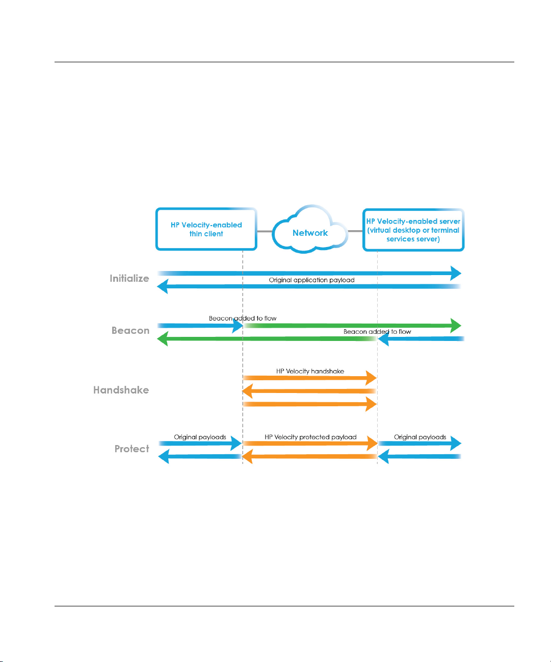
Establishing a connection
An HP Velocity-protected connection is established over four steps (Figure 1):
• Initialization
• Beaconing
• Handshaking
• Protected state
Figure 1. Establishing a connection
Initialization
During initialization, HP Velocity-enabled endpoints start streaming data transparently. No
optimizations are performed.
HP Velocity Server Side Deployment Guide 9
Page 10
HP Velocity functional overview Establishing a connection
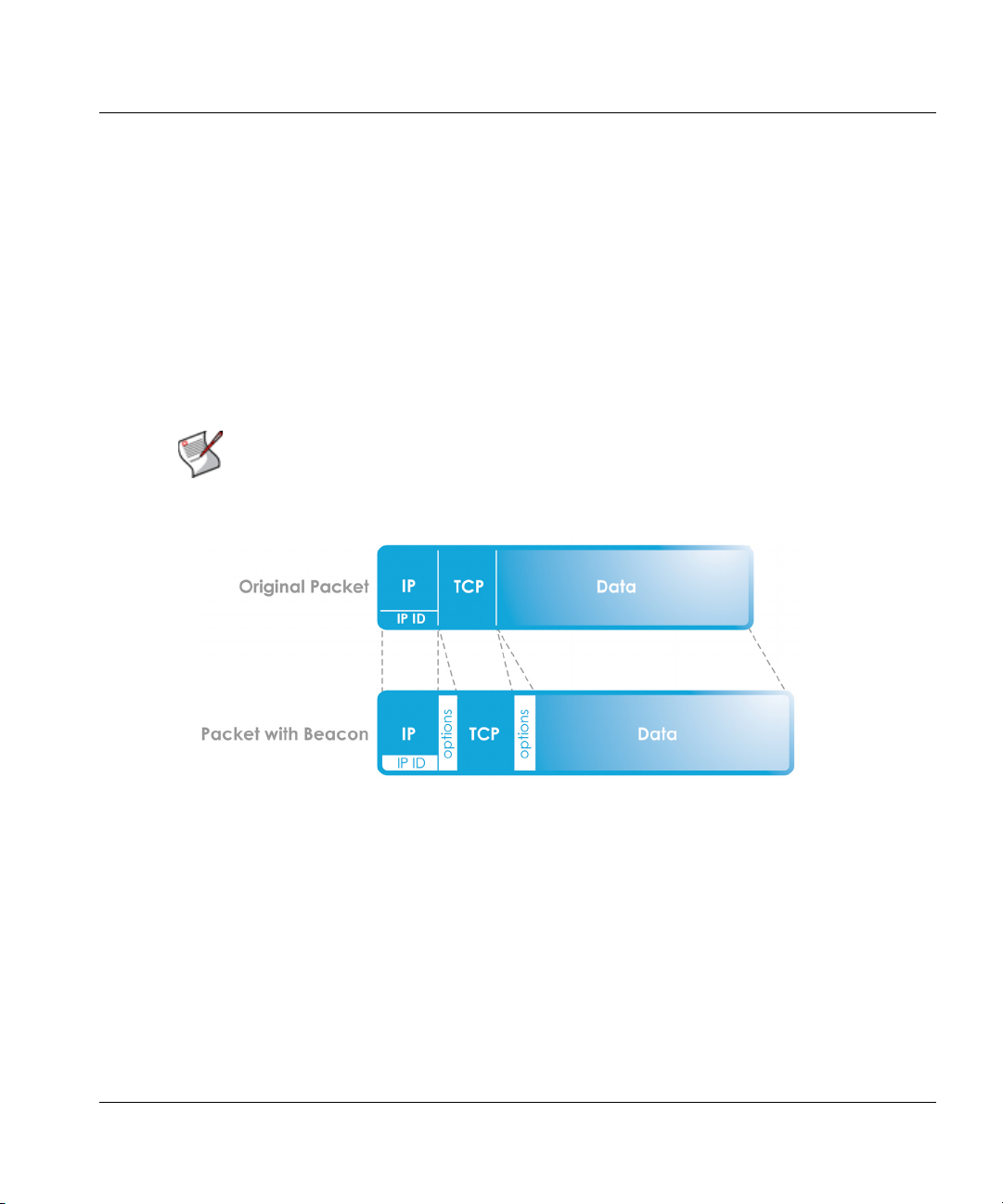
Beaconing
Once an HP Velocity-enabled endpoint detects that a bidirectional network path is available, it
periodically modifies packet headers (both IP and TCP) in a seamless way to advertise itself to
other HP Velocity-enabled endpoints (Figure 2).
IP headers can contain both IP ID-based beacons (using an option value of 0x420B) and IP
Option-based beacons (using an option value of 0x880477FB). TCP flows can use TCP
Option-based beacons (using an option value of 0x01 No-Operation and seven sets of End of
Option Lists 00000000000000).
Once an HP Velocity-enabled endpoint processes enough beacons on a network flow to
discover that another HP Velocity-enabled endpoint is at the other end, handshaking occurs.
NOTE: The use of TCP Option-based beacons for TCP flows and IP
Option-based beacons for UDP flows can be controlled through the
HP Velocity Policy Engine.
Figure 2. IPQ beaconing
Handshaking
An HP Velocity-enabled endpoint will initiate a three-way handshaking procedure with an
HP Velocity-enabled endpoint discovered during beaconing. Once the handshake is
completed, both HP Velocity-enabled endpoints enter the protected state.
Protected state
In the protected state, HP Velocity-enabled endpoints exchange information about current and
trending network conditions. This information is then used to intelligently activate and adjust
various optimizers.
HP Velocity Server Side Deployment Guide 10
Page 11

Deployment configurations
HP Velocity server-side deployments vary based on the virtualization architecture in use.
This chapter covers the following information:
• Deployments
• Deployment considerations
Deployments
HP Velocity is preinstalled on HP thin clients. Use the following table to determine where to
install HP Velocity on the server side.
Virtualization architecture
HP thin clients are directly connected to virtual
desktops or applications.
HP thin clients use a connection broker as a proxy to
access virtual desktops or applications.
The virtualization environment supports both direct
and proxied connections to virtual desktops and
applications.
HP thin clients connect to a terminal services server.
“
Direct” on page 12
“
Proxied” on page 13
“
Direct and proxied” on page 14
“
Terminal services” on page 15
NOTE: HP Velocity server-side components are currently supported on Windows
operating systems.
HP Velocity Server Side Deployment Guide 11
Page 12
Deployment configurations Deployments
Server Side
Original
IP packets
Client
application
Client Side
HP
Velocity
Client
Original
IP packets
Client
application
Client Side
s
s
k
HP
Velocity
Client
Thin Client A
Thin Client B
Application
Virtual
desktop
B
HP
Velocity
Server
Application
Virtual
desktop
A
HP
Velocity
Server
Original
IP packets
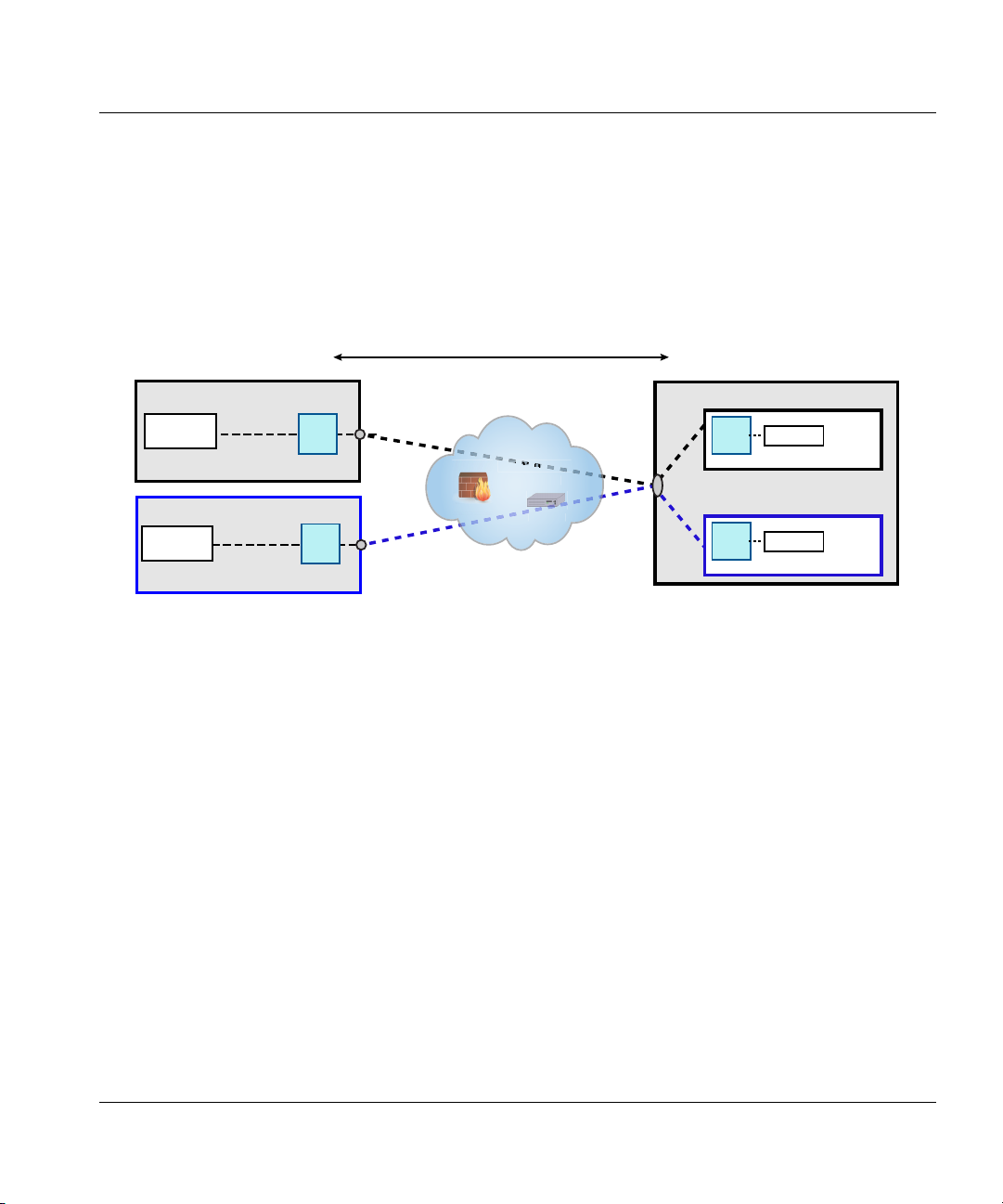
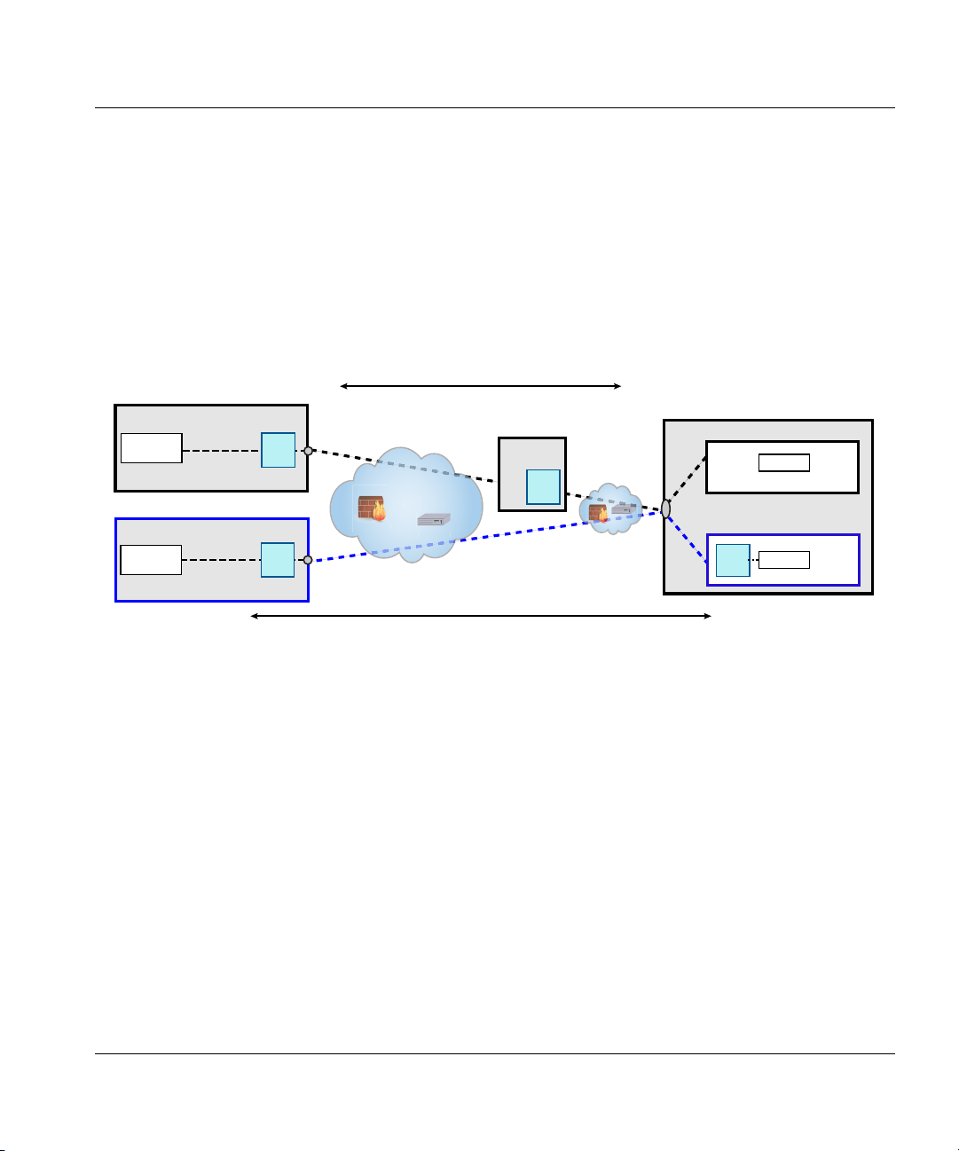
Direct
Virtualization architectures that allow an HP thin client to connect directly to a virtual desktop
must have the HP Velocity server installed on the virtual desktop. In this deployment, a
connection broker does not act as a proxy.
In Figure 3, thin clients A and B are directly connected to their respective virtual desktops A
and B, as indicated by the color of the dotted lines.
Figure 3. Example of a direct deployment
Protected flow between thin client and virtual desktop
networ
Firewall
outer
HP Velocity Server Side Deployment Guide 12
Page 13
Deployment configurations Deployments
Server Side
Application
Virtual
desktop
B
Application
Virtual
desktop
A
Original
IP packets
Client Side
Original
IP packets
Client
application
Client Side
lls
terster
s
k
HP
Velocity
Client
Thin Client A
Thin Client B
Connection
Broker
HP
Velocity
Server
Client
application
HP
Velocity
Client
Original
IP packets
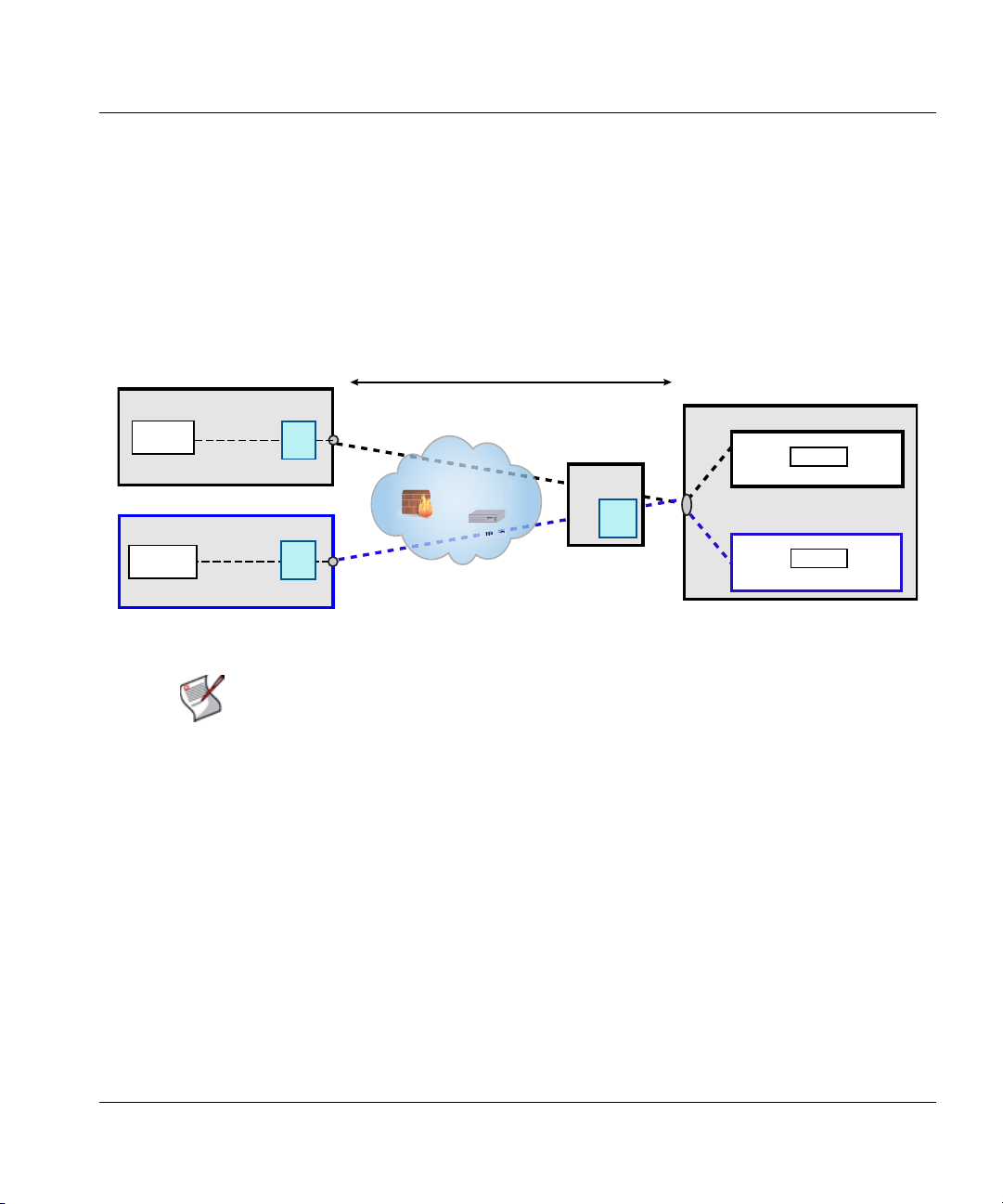
Proxied
Virtualization architectures that require an HP thin client to access their virtual desktop via a
proxy service provided by a connection broker (such as VMware View Manager) must have an
HP Velocity server installed on the connection broker.
In Figure 4, thin clients A and B are connected to their virtual desktops via the connection
broker. An HP Velocity server is installed on the connection broker. This results in flows that
are protected by HP Velocity between the thin clients and the connection broker.
Figure 4. Example of a proxied deployment
Protected flows between thin client and connection broker
nmana
rewa
wor
NOTE: Additional configuration is not required after the HP Velocity server is
installed on the connection broker.
HP Velocity Server Side Deployment Guide 13
Page 14
Deployment configurations Deployments
Protected flow between thin client and virtual desktop
Protected flow between thin client and connection broker
Server Side
Original
IP packets
Client
application
Client Side
HP
Velocity
Client
Original
IP packets
Client
application
Client Side
s
d
wor
k
HP
Velocity
Client
Thin Client A
Thin Client B
Connection
Broker
HP
Velocity
Server
Original
IP packets
Application
Virtual
desktop
A
Application
Virtual
desktop
B
HP
Velocity
Server
Direct and proxied
Some virtualization architectures allow both direct and proxied access to virtual desktops. In
this deployment, the HP Velocity server must be installed on:
• Virtual desktops that are accessed directly
• Connection brokers that provide a proxy service to access the virtual desktop
In Figure 5, thin client A connects to virtual desktop A through the connection broker, and thin
client B connects to virtual desktop B directly.
Figure 5. Example of a direct and proxied deployment
nmanage
irewall
outers
HP Velocity Server Side Deployment Guide 14
Page 15
Deployment configurations Deployments
Original
IP packets
Client
application
Client Side
s
s
Client Side
HP
Velocity
Client
Thin client A
Thin client B
Terminal services / virtual desktop server
Word
Applications
Mail
Applications
Virtual
desktop
HP
Velocity
Server
Original
IP packets
Client
application
HP
Velocity
Client
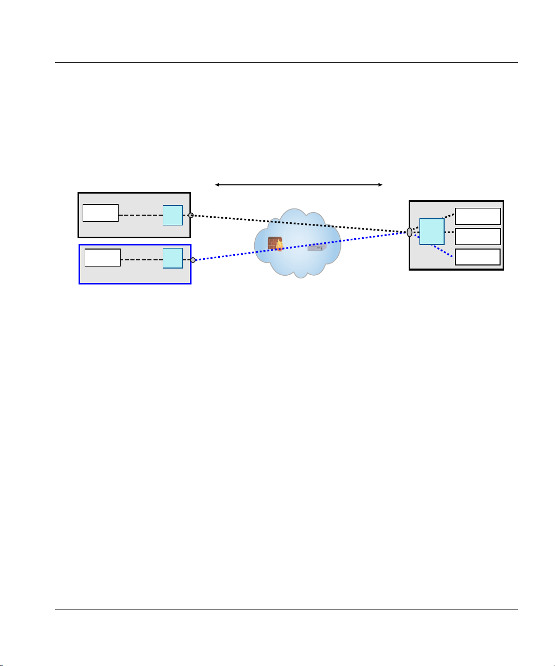
Terminal services
In a terminal services deployment, multiple HP thin clients are connected to a terminal
services server such as a Windows Server.
In this deployment, the HP Velocity server must be installed on the terminal services server
(Figure 6).
Figure 6. Example of a terminal services deployment
Protected flows - Multiple thin clients to terminal services server
irewall
outer
HP Velocity Server Side Deployment Guide 15
Page 16

Deployment configurations Deployment considerations
Deployment considerations
Maximum number of protected flows
HP Velocity supports a range of 16 to 1024 simultaneously protected flows.
The minimum supported protected flows are:
• 16 for HP thin clients
• 16 for virtual desktops
• 256 terminal services servers
HP Velocity defaults to the minimum supported simultaneous flows. If the default setting is
changed, the system must be rebooted for the change to take effect.
NOTE: HP Velocity server-to-server flows are only monitored, not protected. Only
flows between a server enabled with HP Velocity and an HP thin client are
protected.
NOTE: LiveTCP will provide latency mitigation for up to 32 simultaneous
protected flows.
About HP Velocity beacons
HP Velocity advertises its presence in a non-intrusive way by modifying IP and TCP headers
in compliance with International Engineering Task Force (IETF) standards.
If either IP or TCP Option beacons are enabled, HP Velocity will add up to 4 bytes of data to
the IP or TCP headers. This is in compliance with RFC 791 and RFC 793. Some applications
might not be compliant with RFC 791 or RFC 793, and as a result might not be able to process
IP or TCP Option beacons. If this occurs, disabling IP and/or TCP Option beacons should
resolve the issue.
For more information on configuring beacons, see the HP Velocity User Guide.
NOTE: HP Velocity beacons are:
IP Option - 0x880477FB (UDP Flows)
TCP Option - 0x010000000000000000 (TCP Flows)
HP Velocity Server Side Deployment Guide 16
Page 17

Installations
This section outlines the requirements for installing the HP Velocity server and covers the
following information:
• System requirements
• Server-side installation
• Installing HP Velocity on Microsoft Hyper-V
• Installing HP Velocity on servers with Broadcom teaming interfaces
System requirements
Before installing the HP Velocity server, ensure that the following resources are available. The
different requirements for server operating system (OS) and virtual desktop OS installations.
Requirement Server OS Virtual desktop OS
CPU Any Any
Memory 30 MB 3 MB
Disk space 10 MB 10 MB
OS Windows Server 2008
OS variants 32-bit and 64-bit
Clients HP thin clients
Windows Server 2003
Windows 8
Windows 7
Windows Vista
Windows XP (SP3 and above)
NOTE: Memory requirements are proportional to the number of simultaneous
protected flows supported by HP Velocity.
HP Velocity Server Side Deployment Guide 17
Page 18
Installations Server-side installation
Server-side installation
HP Velocity installs as a network driver on the following platforms:
• Virtual desktops
• Host OS of Microsoft Terminal Services
• Microsoft Hyper-V server
NOTE: During installation, HP Velocity will reset the system’s network
interfaces, briefly interrupting network connections. If HP Velocity is
installed over a remote connection, network connectivity might be
disrupted.
To install HP Velocity server:
1. Locate the correct HP Velocity server installation package for the server-side operating
system (see the following table). Read the release notes and documentation for the version
of HP Velocity being installed.
.
Supported operating systems • Server: Windows Server 2003, Windows Server 2008
• Virtual desktop: Windows 8, Windows 7, Windows Vista,
Windows XP
32-Bit Installer HPVelocity_SERVER_32_REL#_R#.msi
64-Bit Installer HPVelocity_SERVER_64_REL#_R#.msi
Note: In the HP Velocity package filename, REL# is the software release
number and R# is the revision number of the package that matches the
release number.
2. Log on as an administrator to the system where the HP Velocity server will be installed.
3. Select the appropriate installation package for the server-side operating system and
architecture, and start the installer.
The Welcome to the HP Velocity Setup Wizard screen appears.
4. Click Next.
The License Agreement screen appears.
5. Read the end user license agreement:
HP Velocity Server Side Deployment Guide 18
Page 19

Installations Server-side installation
•Select I Agree and click Next to continue.
•Select Cancel to end the installation.
The Select Installation Folder screen appears with the default location
C:\Program Files\LiveQoS\HP Velocity\.
6. Either select the location where HP Velocity will be installed or accept the default location.
7. Either select Everyone (default) to install HP Velocity for all user accounts and
administrators or select Just me to install HP Velocity only for the current user account.
8. Click Next.
The Confirm Installation screen appears.
9. Click Next to confirm the selections and start installing HP Velocity.
IMPORTANT: Depending on the version of the Windows OS, a warning
message about software installed by LiveQoS might appear. This
message is expected; allow the installation to proceed.
The Installation Complete screen appears when the installation is finished.
10. Click Close.
NOTE: If you are installing on Microsoft Hyper-V, see “Installing
HP Velocity on Microsoft Hyper-V” on page 20.
NOTE: If you are installing on servers with Broadcom teaming interfaces,
see “Installing HP Velocity on servers with Broadcom teaming interfaces”
on page 21
HP Velocity Server Side Deployment Guide 19
Page 20
Installations Installing HP Velocity on Microsoft Hyper-V
Installing HP Velocity on Microsoft Hyper-V
Installing HP Velocity on Microsoft Hyper-V might require the following additional steps.
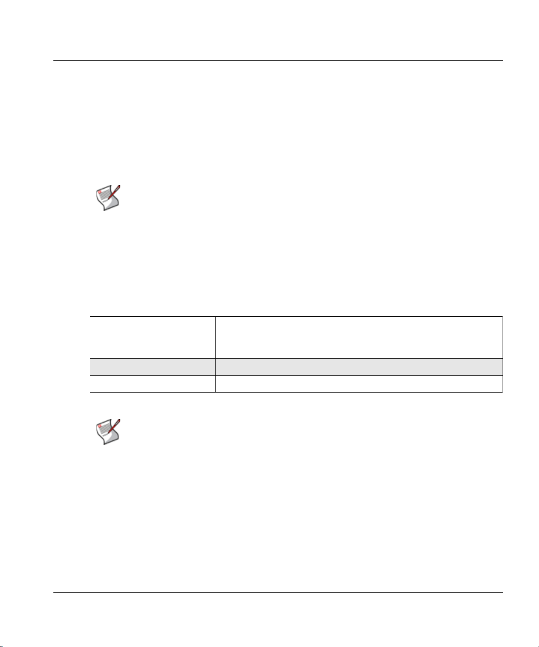
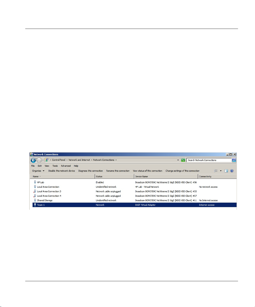
If HP Velocity is installed directly on Microsoft Hyper-V and there is a “Local Area Connection Virtual Network” entry (Figure 7), ensure that the LiveQoS NDIS 6 Filter Driver is disabled for
the physical network adapter (Figure 8).
Figure 7. Microsoft Hyper-V network connections
Figure 8. Disabled LiveQoS NDIS 6 Filter Driver
HP Velocity Server Side Deployment Guide 20
Page 21
Installations Installing HP Velocity on servers with Broadcom teaming inter-
Installing HP Velocity on servers with Broadcom teaming interfaces
Installing HP Velocity on Windows Servers using the Broadcom Advanced Control Suite NIC
Teaming feature might require the following additional steps.
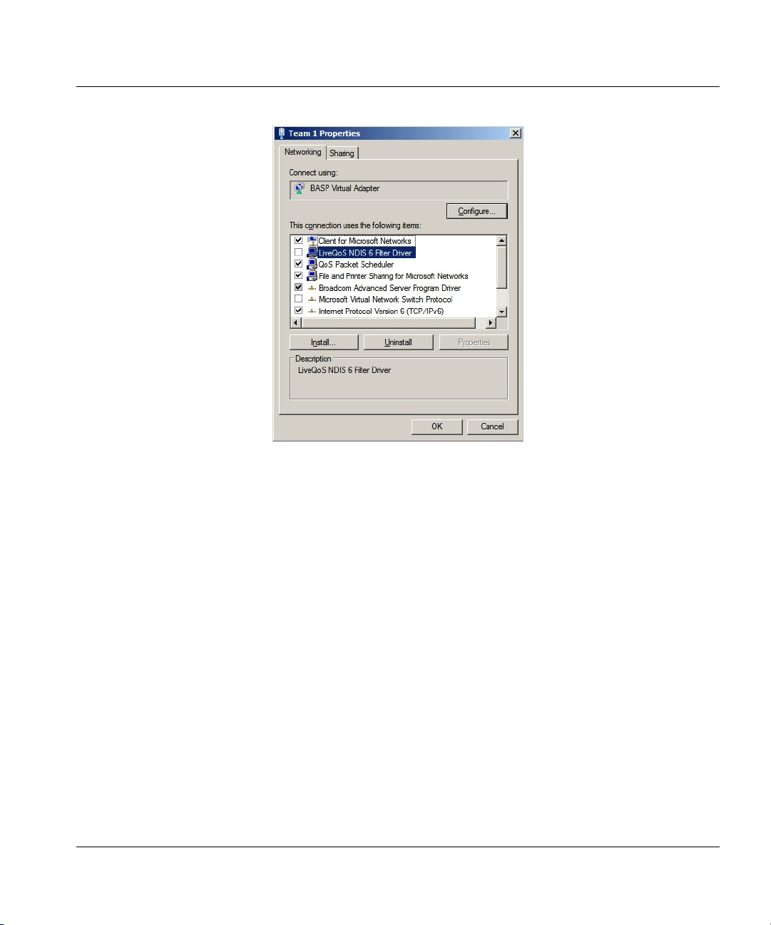
If HP Velocity is installed on Windows Servers, ensure that the LiveQoS NDIS 6 Filter Driver is
disabled in the adapter settings (Figure 10).
To disable the LiveQoS NDIS 6 Filter Driver:
1. Install the HP Velocity server-side component as described in “Server-side installation” on
page 18.
2. Once the installation is complete, a prompt asking to reboot the system will appear. Click
NO.
3. Open the Network and Sharing Center from the Control Panel.
4. Click Change Adapter Settings.
5. Right-click Team 1 (Figure 9).
Figure 9. Adapter settings
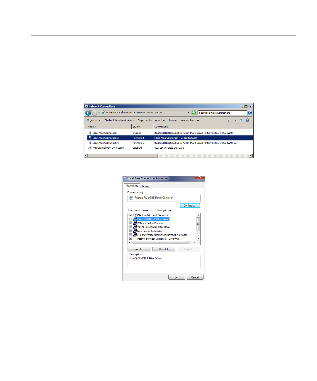
6. In the list titled This connection uses the following items, deselect the checkbox next to
LiveQoS NDIS 6 Filter Driver (Figure 10).
HP Velocity Server Side Deployment Guide 21
Page 22
Installations HP thin client installation
Figure 10. Setting adapter properties
7. Click OK.
HP thin client installation
HP Velocity is preinstalled on select HP thin client images as of March 2012. HP Velocity
updates may be available as an add-on. For more information, visit http://www.hp.com/
support.
HP Velocity Server Side Deployment Guide 22
Page 23

HP Velocity management
This section covers the following information:
• HP Velocity Management Application modes
• Identifying the HP Velocity operational mode on Windows
• Setting the HP Velocity operational mode
HP Velocity Management Application modes
HP Velocity supports two Management Application display modes on Windows: Basic and
Advanced.
• Basic mode is launched by clicking the HP Velocity Management Application icon in the
taskbar. By default, the Basic mode is enabled for HP thin clients.
• Advanced mode provides a toolset for monitoring and troubleshooting HP Velocity-
protected flows and is launched by right-clicking the HP Velocity Management Application
icon in the taskbar (Figure 11) and selecting Management. By default, the Advanced mode
is enabled for server-side installations. For information, see “Using the Management
Application” on page 45.
Identifying the HP Velocity operational mode on Windows
The HP Velocity Management Application automatically launches on system startup and runs
in the background. The HP Velocity Management Application icon appears in the Windows
taskbar (Figure 11).
Figure 11. HP Velocity taskbar icon on Windows
The HP Velocity Management Application icon appears in one of four colors that correspond to
the HP Velocity operational modes (Tab le 1).
HP Velocity Server Side Deployment Guide 23
Page 24

HP Velocity management Setting the HP Velocity operational mode
Table 1. HP Velocity icon color codes
Icon Color Mode Description
Green Protect HP Velocity is protecting one or more flows.
Blue Protect
Orange Monitor
Gray Off HP Velocity is disabled.
NOTE: In the case of server-to-server connections, HP Velocity only
supports monitoring of flows.
HP Velocity is protecting, but flows have not been
established.
HP Velocity is profiling present and trending network
conditions. In this mode, HP Velocity does not
protect flows.
Setting the HP Velocity operational mode
Once the HP Velocity Management Application is running, set the HP Velocity operational
mode. For more information, see “Operational modes” on page 8.
An administrator should only change the HP Velocity operational mode:
• During troubleshooting to disable HP Velocity
• After troubleshooting to re-enable HP Velocity
• As directed by HP support
HP Velocity Server Side Deployment Guide 24
Page 25

HP Velocity management Setting the HP Velocity operational mode
To set the HP Velocity operational mode:
1. Click the HP Velocity icon in the Windows taskbar (Figure 11).
2. On the HP Velocity Mode slider, select an operational mode (Figure 12).
Figure 12. HP Velocity Mode slider
NOTE: Windows administrator privileges are required to change the
HP Velocity mode of operation.
Displaying the protected or monitored flow count
When HP Velocity is in Protect mode, position the cursor over the HP Velocity icon to display a
tooltip with the number of active connections.
When HP Velocity is running on an HP thin client, virtual desktop, or a terminal server, an icon
appears in the taskbar (Figure 11).
HP Velocity Server Side Deployment Guide 25
Page 26

HP Velocity group policy
HP Velocity is installed with a default configuration suitable for most deployments. This chapter
describes how to create a custom HP Velocity configuration:
• HP Velocity Policy Engine
• Configuring HP Velocity using Group Policy
• About the HP Velocity Administrative Template
• Registry keys used in HP Velocity configuration
NOTE: The information in this chapter is intended for the IT staff
administrating HP Velocity.
HP Velocity Policy Engine
The HP Velocity Policy Engine uses Microsoft Group Policy.
Microsoft Group Policy
Microsoft Group Policy provides centralized management and configuration of users and
computers in a Windows Active Directory environment. The Group Policy (GP) and the Active
Directory (AD) infrastructure enable IT administrators to deploy and manage IT policies
centrally. Group Policy settings are contained in a Group Policy object (GPO). HP Velocity can
be configured using Group Policy and the HP Velocity administrative template. For information,
see “Configuring HP Velocity using Group Policy” on page 27.
To create a GPO, use the Group Policy Management Console (GPMC), which is available for
download from the Microsoft Download Center website.
The GPO can be used to centrally manage and propagate new settings for HP Velocity over an
entire Windows AD domain.To manage HP Velocity using Microsoft Group Policy, the
HP Velocity Administrative Template must be applied to the GPO. For more information, see
“Adding the HP Velocity Administrative Template to a GPO” on page 27 and “About the
HP Velocity Administrative Template” on page 29.
The HP Velocity Administrative Template adds a set of options to the GPO and specifies which
registry keys will be set for each option. For more information on the HP Velocity registry keys,
see “Registry keys used in HP Velocity configuration” on page 39.
HP Velocity Server Side Deployment Guide 26
Page 27

HP Velocity group policy Configuring HP Velocity using Group Policy
Configuring HP Velocity using Group Policy
This section provides instructions on how to add the Administrative Template to the GPO and
update the HP Velocity configuration using the Group Policy Editor.
Adding the HP Velocity Administrative Template to a GPO
Choose the Group Policy Editor for the GPO to be edited:
• For local group policy administration, use gpedit.msc.
• For domain group policy administration, use gpmc.msc and select the applicable GPO.
To add the HP Velocity Group Policy Administrative Template to a GPO:
1. Open the appropriate Group Policy Editor (Figure 13).
Figure 13. Adding an Administrative Template
2. Expand Computer Configuration, and navigate to the Administrative Templates folder.
3. Right-click Administrative Templates.
4. Click Add/Remove Templates.
5. Click Add.
6. Browse for hp_velocity_configuration_REL#-R#.adm, where REL# is the software
release number and R# is the revision number of the template that matches the release
number of the HP Velocity install.
7. Click Close.
The HP Velocity Group Policy Administrative Template has been applied to the GPO.
HP Velocity Server Side Deployment Guide 27
Page 28

HP Velocity group policy Configuring HP Velocity using Group Policy
Updating the HP Velocity configuration using the Group Policy Editor
Once the Administrative Template has been added to the GPO, configuration changes for
HP Velocity can be made as required.
HP recommends that HP Velocity settings be changed on all systems in an organizational unit
(OU). This ensures that all installations in the OU use the same settings.
To change HP Velocity settings on all systems in an OU:
1. Open the GPO in the Group Policy Management Editor.
2. Expand Computer Configuration > Policies.
3. Expand Administrative Templates > Classic Administrative Templates (ADM).
4. Select HP Velocity.
5. Double-click the component to update it (Figure 14).
Figure 14. Updating a policy configuration
6. Navigate to the next component by clicking Next Setting or Previous Setting.
7. Click OK.
HP Velocity Server Side Deployment Guide 28
Page 29

HP Velocity group policy About the HP Velocity Administrative Template
NOTE: If the HP Velocity Management Application is not running,
changes using Group Policy are applied after a system reboot or the next
time the Management Application is restarted.
About the HP Velocity Administrative Template
The Administrative Template (Figure 15) consists of policies that allow administrators to create
a custom configuration for HP Velocity. The Administrative Template filename is
hp_velocity_configuration_REL#-R#.adm, where REL# is the software release number
and R# is the revision number of the template that matches the release number of the
HP Velocity install.
Figure 15. HP Velocity Administrative Template as shown in the Group Policy Editor
The following sections provide information on how to configure the policies in the HP Velocity
Administrative Template:
• Management Application Mode
• System Settings
• Boot Settings
• Policy Filters (Port & IP)
• LiveQ - Target Loss Rate Filters
• LiveTCP - Protocol Latency Mitigation Policy Filters
• LiveQ - Packet Loss Protection
HP Velocity Server Side Deployment Guide 29
Page 30

HP Velocity group policy About the HP Velocity Administrative Template
• LiveTCP - Latency Mitigation
• Logging
NOTE: For more information about HP Velocity settings, see “Registry
keys used in HP Velocity configuration” on page 39.
Management Application Mode
The Advanced Management Application provides a toolset for monitoring and debugging
network flows using HP Velocity, as well as the ability to temporarily override configuration
settings.
Table 2. Management Application Mode
Setting Default Options
Advanced Management
Application Mode
Thin Client: Disabled
Server Side: Enabled
Enable or disable the presence of the
HP VelocityAdvanced Management
Application.
System Settings
HP Velocity global system settings include the operational mode; enabled or disabled
optimizers; packet loss protection, latency mitigation, and beaconing settings; and network
maximum transmission unit (MTU).
Table 3. System settings
Setting Default Options
Operational Mode Protect
• Protect: HP Velocity provides session
establishment, session statistics, packet loss
protection, WiFi optimization, and latency
mitigation.
• Monitor: HP Velocity continuously profiles the
end-to-end network conditions over
established flows, but the HP Velocity network
optimizers are disabled.
• Off: HP Velocity passes all network flows
transparently and does not perform any
monitoring or optimization.
HP Velocity Server Side Deployment Guide 30
Page 31

HP Velocity group policy About the HP Velocity Administrative Template
Setting Default Options
LiveQ - Packet Loss
Protection
LiveTCP - Latency Mitigation Enabled Enable or disable LiveTCP - Latency Mitigation.
LiveTCP - Flow Control
Optimizer
LiveWiFi Optimizer Enabled Enable or disable LiveWiFi Optimizer.
IP Option Beacon Enabled Enable or disable the use of IP Option beacon
TCP Option Beacon Enabled Enable or disable the use of TCP Option
Network MTU 1492 Specify the MTU that can be processed within
Enabled Enable or disable LiveQ - Packet Loss
Protection.
Protects application flows from packet loss by
automatically adapting the amount of added
redundancy.
Provides latency mitigation for RDP, RGS, and
ICA protocols.
Disabled Enable or disable LiveTCP - Flow Control
Optimizer.
Improves the throughput of applications like
multimedia streaming and remote desktop
access by modifying TCP flow control
mechanisms to perform better in WiFi
environments.
Ensures that HP Velocity-protected flows
experience lower latency, lower jitter, and higher
throughput.
(0x880477FB) for UDP flows.
beacon (0x01000000 & 0x00000000) for TCP
flows.
the network.
Range is 750 to 1500 bytes.
NOTE: If the IP Option Beacon or TCP Option Beacon setting is
enabled, HP Velocity will add up to 4 bytes of data to IP or TCP headers.
This is in compliance with RFC 791 and RFC 793. Some applications
might not be compliant with RFC 791 or RFC 793, and as a result might
not be able to process IP or TCP Option beacons. If this occurs, disabling
the IP Option Beacon or TCP Option Beacon setting should resolve the
issue.
HP Velocity Server Side Deployment Guide 31
Page 32

HP Velocity group policy About the HP Velocity Administrative Template
Boot Settings
HP Velocity system boot settings specify the number of protected flows and whether the
collection of local and remote system information is enabled or disabled.
Table 4. Boot settings
Setting Default Options
Number of protected
flows
Local System
Information Collection
Remote System
Information Collection
Thin Client: 16
Server Side Desktop OS: 16
Server Side Server OS: 256
Enabled Enable or disable local system information
Enabled Enable or disable remote system information
Set the maximum number of simultaneously
protected flows. HP Velocity supports 16 to
1024 protected flows.
collection.
Indicates that the local endpoint is configured to
send its system information and per-flow
statistics to the remote endpoint.
collection.
Indicates that the local endpoint will process
and display remote endpoint system information
and per-flow statistics received.
Policy Filters (Port & IP)
Policy filters can be used to specify the IP addresses and ports of the flows to be protected by
HP Velocity and the level of protection applied to the filtered flows.
The following formats must be used when configuring the policy filters:
• IP Address: Use a space-separated list of CIDR-format IP addresses and subnet mask
pairs. For example, 192.168.1.0/24 145.76.53.3/32.
• Port: Use a space-separated list of ports. For example, 80 1750 1751.
Table 5. Policy Filters (Port & IP) settings
Setting Default Options
Transparent TCP Ports 21 53 2869 9100 17500 Transparent port filters for TCP and UDP:
The transparent port filter allows administrators
Transparent UDP Ports 53 67 68 123 161 500 4500
17500
HP Velocity Server Side Deployment Guide 32
to specify a list of TCP/UDP ports for which
flows will not be protected by HP Velocity.
Page 33

HP Velocity group policy About the HP Velocity Administrative Template
Setting Default Options
Special TCP Ports 554 1720 5060 1723 Special Port Filter for TCP and UDP:
Special UDP Ports 554 5060
Whitelist TCP Ports Whitelist filter for TCP and UDP:
Whitelist UDP Ports
IP Address Blacklist
Filter
255.255.255.255/32 Blacklist IP filter:
The special port filter allows administrators to
enable or disable support for specific protocols.
By default, the special port filter is preconfigured to include ports that provide special
protocol support, such as RTSP (554), H.323
(1720), PPTP (1723), and SIP (5060).
To disable support for a specific protocol,
remove the corresponding port from the filter.
For example, to disable support for RTSP,
remove port 554 from the special TCP and UDP
port filters.
If a whitelist port filter is specified, only the traffic
meeting the following criteria is protected by
HP Velocity:
• The destination IP address for the traffic is not
specified in the blacklist IP filter.
• The destination IP address for the traffic is
specified in the whitelist IP filter.
• The destination port for the traffic is specified
in the whitelist port filter.
All traffic not meeting these criteria will be
passed through transparently.
The first IP filter to be evaluated is the blacklist
filter, which allows administrators to specify the
destination IP addresses where traffic will not
be protected by HP Velocity. If an IP address of
a specified destination matches an IP address
specified in the blacklist, it will be passed on
transparently. Administrators can use a blacklist
in conjunction with a whitelist. For example, use
the blacklist to exclude specific IP addresses in
a whitelisted subnet from being protected by
HP Velocity.
HP Velocity Server Side Deployment Guide 33
Page 34

HP Velocity group policy About the HP Velocity Administrative Template
Setting Default Options
IP Address Whitelist
Filter
Whitelist IP filter:
The whitelist IP filter is evaluated after the
blacklist IP filter. It applies only to those IP
addresses that pass through the blacklist IP
filter. The whitelist IP filter allows administrators
to specify a list of destination IP addresses to
which HP Velocity protection will be applied.
The whitelist filter is exclusive.
LiveQ - Target Loss Rate Filters
The target loss rate (TLR) filters allow administrators to specify the IP addresses and ports
that are associated with a particular target loss rate.
The following formats must be used when configuring the policy filters:
• IP Address: Use a space-separated list of CIDR-format IP addresses and subnet mask
pairs. For example, 192.168.1.0/24 145.76.53.3/32.
• Port: Use a space-separated list of ports. For example, 80 1750 1751.
Table 6. LiveQ - Target Loss Rate Filter settings
Setting Default Options
Target Loss Rate Filters TLR Filters:
Separate IP and port filters are provided for
each supported target loss rate:
0.4% Target Loss Rate IP Filters
0.4% Target Loss Rate TCP Filters
0.4% Target Loss Rate UDP Filters
0.2% Target Loss Rate IP Filters
0.2% Target Loss Rate TCP Filters
0.2% Target Loss Rate UDP Filters
0.1% Target Loss Rate IP Filters
0.1% Target Loss Rate TCP Filters
0.1% Target Loss Rate UDP Filters
0.04% Target Loss Rate IP Filters
0.04% Target Loss Rate TCP Filters
0.04% Target Loss Rate UDP Filters
HP Velocity Server Side Deployment Guide 34
Page 35

HP Velocity group policy About the HP Velocity Administrative Template
LiveTCP - Protocol Latency Mitigation Policy Filters
LiveTCP - Latency Mitigation policy filters can be enabled or disabled for RDP, RGS, and ICA
protocols.
Table 7. LiveTCP - Protocol Latency Mitigation Policy Filter settings
Setting Default Options
RDP Port 3389 Specify the port number used for RDP.
RDP Policy Enabled Enable or disable LiveTCP latency mitigation for
the RDP protocol.
RGS Port 42966 Specify the port number used for RGS.
RGS Policy Enabled Enable or disable LiveTCP latency mitigation for
the RGS protocol.
ICA Port 1494 and 2598 Specify the port number used for ICA.
ICA Policy Enabled Enable or disable LiveTCP latency mitigation for
the ICA protocol.
LiveQ - Packet Loss Protection
HP Velocity protects application flows from packet loss by automatically adapting the amount
of added redundancy.
Table 8. LiveQ - Packet Loss Protection settings
Setting Default Options
Global Target Loss Rate 0.04% Specify the loss rate that HP Velocity will attempt to
achieve for all active HP Velocity-protected flows.
Options are:
• 0.04%
• 0.1%
• 0.2%
• 0.4%
HP Velocity Server Side Deployment Guide 35
Page 36

HP Velocity group policy About the HP Velocity Administrative Template
Setting Default Options
Congestion Avoidance Enabled Enable or disable congestion avoidance.
HP Velocity Congestion Avoidance automatically
adjusts HP Velocity protection to accommodate
detected bandwidth constraints. When Congestion
Avoidance is active and bandwidth constraints are
detected, the bandwidth and default TLR settings
described in this table are overridden to ensure the
best network performance possible.
Bandwidth Control Dynamic Set the protection mode that HP Velocity is able to
use when encoding HP Velocity-protected flows:
• Dynamic: Use this mode in environments where
bandwidth is not constrained. It maximizes
performance while minimizing the required
bandwidth.
• Low: Use this mode in extremely bandwidthconstrained environments to cap the estimated
HP Velocity protection overhead at or below 27%.
• Medium: Use this mode in moderately bandwidthconstrained environments to cap the estimated
HP Velocity protection overhead at or below 40%.
• High: Use this mode to maximize performance in
environments where bandwidth is not constrained
and the network loss is known to be high. This
mode differs from the Dynamic mode in that it uses
aggressive encoding as soon as it detects
HP Velocity at the far end without first measuring
the loss in the network.
Burst Loss Protection Auto Set Burst Loss Protection (BLP) to protect against
correlated loss in the network.
Options are:
• Off: Disables BLP for correlated loss.
• Active: Enables BLP for correlated loss.
• Auto: Allows the HP Velocity Device Driver to
determine if BLP is needed and automatically turn
on processing if required.
BLP Buffer (ms) 20 ms Set the amount of packet buffering in milliseconds
that HP Velocity can use when protecting against
correlated loss.
Values range from 10 ms to 100 ms in increments of
10 ms.
HP Velocity Server Side Deployment Guide 36
Page 37

HP Velocity group policy About the HP Velocity Administrative Template
LiveTCP - Latency Mitigation
HP Velocity LiveTCP - Latency Mitigation optimizes TCP throughput and provides latency
mitigation for RDP, RGS, and ICA protocols.
Table 9. LiveTCP - Latency Mitigation settings
Setting Default Options
Latency Threshold 20 ms Set the latency threshold in milliseconds. Latency
mitigation is activated once this threshold is
exceeded.
Congestion Control Aggressive Set the degree of congestion control required.
Aggressive: Handles the effects of a high-latency
network.
TCP Friendly: Uses the standard TCP-like
congestion control algorithm.
HP Velocity Server Side Deployment Guide 37
Page 38

HP Velocity group policy About the HP Velocity Administrative Template
Logging
HP Velocity logs provide detailed endpoint statistics on a per-flow and per-flow-record basis.
HP Velocity maintains the statistics history for up to seven days. Logs are stored in the
temporary folder for the current user. For example,
C:\Users\<username>\AppData\Local\Temp. The log filename format is
HPVelocity_logtype_yymmdd.log.
Table 10. Logging settings
Setting Default Options
Statistics Logging Disabled Set the endpoint network statistics logging time
interval. Statistics include network loss rates,
corrected loss rates, throughputs, and latency.
Options are:
• Disabled
• Every 5 Seconds
• Every Minute
• Every 5 Minutes
Flow Logging Disabled Set the flow logging time interval. Per-flow
statistics include network loss rates, corrected
loss rates, throughputs, and latency.
Options are:
• Disabled
• Every 5 Seconds
• Every Minute
• Every 5 Minutes
Flow Records Disabled Enable or disable flow records collection.
Captured when a flow is terminated, the flow
record documents the details of the flow,
including system information, flow duration, and
network statistics.
HP Velocity Server Side Deployment Guide 38
Page 39

HP Velocity group policy Registry keys used in HP Velocity configuration
Registry keys used in HP Velocity configuration
The following sections list the registry keys (grouped by category) used by HP Velocity.
• Management Application key
• System Settings keys
• Boot Settings keys
• Policy Filters (Port and IP) keys
• LiveQ - Target Loss Rate (TLR) Policy Filters keys
• LiveTCP - Protocol Latency Mitigation Policy Filters keys
• LiveQ - Packet Loss Protection keys
• LiveTCP - Latency Mitigation keys
• Logging keys
HP Velocity Server Side Deployment Guide 39
Page 40

HP Velocity group policy Registry keys used in HP Velocity configuration
Management Application key
Registry key Parameter
Software\Policies\IPQ\CurrentVersion\AdvancedMgmtAppMode Advanced Management Application
mode
System Settings keys
Registry key Parameter
Software\Policies\IPQ\CurrentVersion\Protection Protection configuration
Software\Policies\IPQ\CurrentVersion\LiveQMode Loss protection configuration
Software\Policies\IPQ\CurrentVersion\LiveTCPMode Latency mitigation mode
Software\Policies\IPQ\CurrentVersion\TCPOptimizer TCP Optimizer configuration
Software\Policies\IPQ\CurrentVersion\WifiOptimizer WiFi Optimizer configuration
Software\Policies\IPQ\CurrentVersion\IPOptionMarking IP Option beaconing configuration
Software\Policies\IPQ\CurrentVersion\TCPOptionMarking TCP Option beaconing configuration
Software\Policies\IPQ\CurrentVersion\MTU Network Maximum Transmission Unit
(MTU) configuration
Boot Settings keys
Registry key Parameter
Software\Policies\IPQ\CurrentVersion\NumProtectedSessions Protected flows
Software\Policies\IPQ\CurrentVersion\LocalMetrics Local system information collection
Software\Policies\IPQ\CurrentVersion\RemoteMetrics Remote system information collection
HP Velocity Server Side Deployment Guide 40
Page 41

HP Velocity group policy Registry keys used in HP Velocity configuration
Policy Filters (Port and IP) keys
Registry key Parameter
Software\Policies\IPQ\CurrentVersion\IPBlacklistFilters Blacklist IP filter configuration
Software\Policies\IPQ\CurrentVersion\IPWhitelistFilters Whitelist IP filter configuration
Software\Policies\IPQ\CurrentVersion\TCPTransparentFilters Transparent TCP filter configuration
Software\Policies\IPQ\CurrentVersion\UDPTransparentFilters Transparent UDP filter configuration
Software\Policies\IPQ\CurrentVersion\TCPSpecialFilters Special TCP filter configuration
Software\Policies\IPQ\CurrentVersion\UDPSpecialFilters Special UDP filter configuration
Software\Policies\IPQ\CurrentVersion\TCPWhiteFilters Whitelist TCP port filter configuration
Software\Policies\IPQ\CurrentVersion\UDPWhiteFilters Whitelist UDP port filter configuration
HP Velocity Server Side Deployment Guide 41
Page 42

HP Velocity group policy Registry keys used in HP Velocity configuration
LiveQ - Target Loss Rate (TLR) Policy Filters keys
Registry key Parameter
Software\Policies\IPQ\CurrentVersion\DefaultTLRIPFilters Default-level TLR IP filter configuration
Software\Policies\IPQ\CurrentVersion\DefaultTLRTCPFilters Default-level TLR filters, TCP
configuration
Software\Policies\IPQ\CurrentVersion\DefaultTLRUDPFilters Default-level TLR filters, UDP
configuration
Software\Policies\IPQ\CurrentVersion\HighTLRIPFilters High-level TLR IP filter configuration
Software\Policies\IPQ\CurrentVersion\HighTLRTCPFilters High-level TLR filters, TCP
configuration
Software\Policies\IPQ\CurrentVersion\HighTLRUDPFilters High-level TLR filters, UDP
configuration
Software\Policies\IPQ\CurrentVersion\LowTLRIPFilters Low-level TLR IP filters configuration
Software\Policies\IPQ\CurrentVersion\LowTLRIPFilters Low-level TLR filters, TCP
configuration
Software\Policies\IPQ\CurrentVersion\LowTLRUDPilters Low-level TLR filters, UDP
configuration
Software\Policies\IPQ\CurrentVersion\UltraLowTLRIPFilters Ultra-low-level TLR IP filters
configuration
Software\Policies\IPQ\CurrentVersion\UltraLowTLRTCPFilters Ultra-low-level TLR filters, TCP
configuration
Software\Policies\IPQ\CurrentVersion\UltraLowTLRUDPFilters Ultra-low-level TLR filters, UDP
configuration
HP Velocity Server Side Deployment Guide 42
Page 43

HP Velocity group policy Registry keys used in HP Velocity configuration
LiveTCP - Protocol Latency Mitigation Policy Filters keys
Registry key Parameter
Software\Policies\IPQ\CurrentVersion\LiveTcpRdpPort RDP port
Software\Policies\IPQ\CurrentVersion\LiveTcpRdpEnabled RDP enabled by default
Software\Policies\IPQ\CurrentVersion\LiveTcpRgsPort RGS port
Software\Policies\IPQ\CurrentVersion\LiveTcpRgsEnabled RGS enabled by default
Software\Policies\IPQ\CurrentVersion\LiveTcpIcaPort ICA port
Software\Policies\IPQ\CurrentVersion\LiveTcpIcaEnabled ICA enabled by default
LiveQ - Packet Loss Protection keys
Registry key Parameter
Software\Policies\IPQ\CurrentVersion\GlobalTargetLossRate TLR configuration
Software\Policies\IPQ\CurrentVersion\LinkProfiler Congestion Avoidance configuration
Software\Policies\IPQ\CurrentVersion\BandwidthControl Bandwidth control configuration
Software\Policies\IPQ\CurrentVersion\Logging Logging configuration
Software\Policies\IPQ\CurrentVersion\BurstLossProtection BLP configuration
Software\Policies\IPQ\CurrentVersion\MaxBLPBuffer Max-BLP Buffer configuration
LiveTCP - Latency Mitigation keys
Registry key Parameter
Software\Policies\IPQ\CurrentVersion\LiveTcpGlbLatency Latency threshold configuration
Software\Policies\IPQ\CurrentVersion\LiveTcpGlbAlg Congestion control configuration
HP Velocity Server Side Deployment Guide 43
Page 44

HP Velocity group policy Registry keys used in HP Velocity configuration
Logging keys
Registry key Parameter
Software\Policies\IPQ\CurrentVersion\DefaultStatisticsLogging Sets network statistics logging time
interval
Software\Policies\IPQ\CurrentVersion\DefaultFlowLogging Sets flow logging time interval
Software\Policies\IPQ\CurrentVersion\DefaultFlowRecords Enables or disables flow records
HP Velocity Server Side Deployment Guide 44
Page 45

Using the Management Application
The HP Velocity Management Application is a Windows application that provides a toolset for
monitoring and troubleshooting HP Velocity-protected flows. For more information, see
“HP Velocity management” on page 23.
The following sections describe how to use the Management Application user interface:
• Network Statistics
• Network Monitor
• Flow Information
• Configuration
Network Statistics
The Network Statistics tab provides cumulative statistics for HP Velocity-protected flows.
Network statistics provide a real-time view of the network’s performance.
From this tab, basic and advanced statistics can be exported to CSV format for analysis.
This section covers the following information:
• Statistics view
• Advanced Statistics view
• Working with network statistics
HP Velocity Server Side Deployment Guide 45
Page 46

Using the Management Application Network Statistics
Statistics view
The Statistics view provides basic information on how the network is performing (Table 11).
The statistics are accumulated in time-incremented bins (Figure 16). The To ta l column
represents the accumulated statistics since either the system was started or statistics were
last cleared.
Figure 16. Network Statistics view
Table 11. Network statistics
Statistic name Description
Loss - Without Velocity The actual received packet loss rate measured by HP Velocity.
Loss - With Velocity The received packet loss rate after correction by HP Velocity.
Encoded Data Sent The bytes of encoded data, in Kbps for intervals or MB/KB for cumulative
totals, sent by HP Velocity to each remote HP Velocity-enabled endpoint.
Encoded Data Received The bytes of segment data, in Kbps for intervals or MB/KB for cumulative
totals, received by HP Velocity from each remote HP Velocity-enabled
endpoint.
Total Active Flows Number of currently active unique data flows detected by HP Velocity as an
endpoint.
Protected Flows Number of currently active unique protected data flows detected by
HP Velocity as an endpoint.
System Uptime The amount of time since the last power cycle or reboot of the operating
system. Units are HH:MM:SS.
HP Velocity Server Side Deployment Guide 46
Page 47

Using the Management Application Network Statistics
Statistic name Description
Collection Time The amount of time that the Management Application has been collecting
statistics. Units are HH:MM:SS.
NOTE: Collection time is reset when the statistics are cleared.
Advanced Statistics view
The Statistics view displays a subset of the total statistic counters available. Select the
Advanced Statistics check box (Figure 17) to view more detailed information (Ta bl e 1 2).
To return to the Statistics view, deselect Advanced Statistics.
Figure 17. Advanced Statistics view
NOTE: When Clear Statistics is clicked, the Throughput line displayed on
the network graph drops momentarily.
Table 12. Advanced statistics
Statistic name Description
Total Active Flows The number of currently active unique data flows detected by HP Velocity
as an endpoint.
Protected Flows The number of currently active unique protected data flows detected by
HP Velocity as an endpoint.
HP Velocity Server Side Deployment Guide 47
Page 48

Using the Management Application Network Statistics
Statistic name Description
Packets Encoded The number of IP packets that were encoded by HP Velocity into segments.
Segments Sent The number of encoded segments sent by HP Velocity to each remote
HP Velocity-enabled endpoint.
Segments Received The number of encoded segments received by HP Velocity from each
remote HP Velocity-enabled endpoint.
Segments Lost The number of HP Velocity-encoded segments that were not received by
HP Velocity due to packet loss in the network.
Packets Decoded The number of IP packets that HP Velocity successfully reconstructed from
the received encoded segments.
Packets Lost The number of IP packets that HP Velocity was unable to reconstruct from
the received encoded segments due to excessive loss in the network.
Full Packets Lost The number of IP packets that HP Velocity was unable to reconstruct
because it did not receive any encoded segments for the encoded packet.
NOTE: Together with the Packets Lost counter, this counter is an indicator
of burst loss.
High Loss Events The number of times that HP Velocity detected difficulty communicating
with the remote HP Velocity-enabled endpoints due to extremely high
packet loss in the network.
Non-accelerated Packets
Sent
The number of unprotected IP packets sent.
Non-accelerated Packets
Received
Packet Flows Monitored The number of unique data flows detected by HP Velocity.
Accelerated Packet Flows
Unfulfilled
Accelerated Packet Flows
Monitored
Packets Encoded
(Throughput)
Packets Decoded
(Throughput)
Non-accelerated Throughput
(Tx)
HP Velocity Server Side Deployment Guide 48
The number of unprotected IP packets received.
The number of data-flow requests that cannot be fulfilled due to resource
limitations.
The number of unique data flows protected by HP Velocity.
The bytes of IP packet data, in Kbps for intervals or KB/MB for cumulative
totals, received from each application encoded into HP Velocity segments
or monitored by HP Velocity.
The bytes of IP packet data, in Kbps for intervals or KB/MB for cumulative
totals, received from the network that were successfully reconstructed or
monitored by HP Velocity.
The bytes of all transmitted unprotected IP packet data, in Kbps for
intervals or KB/MB for cumulative totals.
Page 49

Using the Management Application Network Statistics
Statistic name Description
Non-accelerated Throughput
(Rx)
The bytes of all received non-protected IP packet data in Kbps for intervals
or KB/MB for cumulative totals.
Working with network statistics
HP Velocity provides controls on the Network Statistics tab (Table 13) for working with the data
available.
Table 13. Network statistics operations
Operation Description
Logging Interval Sets the frequency at which statistics will be logged to the log file. Logging
is enabled when one of the following intervals is selected:
• Every 5 Seconds
• Every Minute
• Every 5 Minutes
Save Log History Export the statistics log to a comma-separated value (CSV) file.
NOTE: The Save Log History control is available only when logging is
enabled.
Save Log Snapshot Saves the current 5-second, 1-minute, and 5-minute interval statistics to a
file with the same column order as the statistics history file.
Clear Statistics Resets statistic counts and collection time to zero.
NOTE: When enabled, logging is available only until the system is reset.
After a reset, logging reverts to the setting specified in the Group Policy, if
applied. Otherwise, it reverts to the default setting (disabled).
NOTE: Log files are stored in the temporary folder for the current user. For
example, C:\Users\<username>\AppData\Local\Temp. The log
filename format is HPVelocity_logtype_yymmdd.log.
HP Velocity Server Side Deployment Guide 49
Page 50

Using the Management Application Network Monitor
Network Monitor
The Network Monitor tab displays information about endpoint network conditions—throughput
and packet loss—as graphs (Ta bl e 1 4).
Low corrected loss with Velocity is optimal when sufficient bandwidth is available (Figure 18).
Figure 18. Network Monitoring graph
Table 14. Network monitoring graphs
Graph name Color Description
Throughput Blue line The received throughput over the most recent interval. The right
axis indicates the throughput in Kbps or Mbps.
With Velocity Green bars The corrected packet loss seen by applications for which
HP Velocity is protecting flows. The left axis indicates the loss as a
percentage.
Without Velocity Red bars The packet loss in the network. The left axis indicates the loss as
a percentage.
HP Velocity Server Side Deployment Guide 50
Page 51

Using the Management Application Flow Information
Additional statistics (Tab le 1 5 ) are displayed to the left of each graph.
Table 15. Additional network loss and network throughput data.
Value Description
Network Loss
Peak The highest packet loss for the duration of the graph.
Without Velocity The packet loss over the most recent interval.
With Velocity The corrected loss over the most recent interval.
Network Throughput
Peak The highest received throughput for the duration of the graph.
Current The received throughput for the most recent interval.
Flow Information
HP Velocity facilitates end-to-end monitoring of network flows and the systems associated by
collecting and reporting an extensive set of statistics displayed on the Flow Information tab
(Figure 19):
• System Information: Operating system, network adapter, CPU, and memory usage
• Endpoint network statistics: Loss rates, corrected loss rates, throughputs, and latency
• Per-flow network statistics: Loss rates, corrected loss rates, throughputs, and latency
Figure 19. Flow Information tab
HP Velocity Server Side Deployment Guide 51
Page 52

Using the Management Application Flow Information
NOTE: For Linux thin clients, flow information can be viewed from the
virtual desktop or terminal services server they are connected to.
Remote system statistics (Ta bl e 1 6) are displayed in the Protected Endpoints pane.
Table 16. Remote system statistics
Statistic name Description
Remote Host The IP address of the remote host.
Product The product name as defined in the System BIOS.
CPU Usage The percentage of CPU in use.
Memory Usage The percentage of memory in use.
Link The type of network link in use.
Statistics for individual protected data flows between two endpoints (Tab le 1 7 ) are displayed in
the Protected Flows pane.
Table 17. Protected data flow statistics
Statistic name Description
Remote IP The remote IP address for the protected flow.
Remote Port The remote TCP or UDP port number for the protected flow. If the port
number is a well-known protocol, the protocol name also appears.
Local IP The local IP address for the protected flow.
Local Port The local TCP or UDP port number for the protected flow. If the port
number is a well-known protocol, the protocol name also appears.
Protocol The protocol (such as TCP or UDP) used by the protected flow.
LiveTCP Indicates whether LiveTCP is protecting the specific flow. The four modes
are:
• Protecting: LiveTCP is providing latency mitigation to the flow.
• Inspecting: LiveTCP is in a monitoring state as the network condition has
not been satisfied to provide protection for this flow.
• Off: LiveTCP is not active.
• N/A: LiveTCP is not applicable for the particular flow.
HP Velocity Server Side Deployment Guide 52
Page 53

Using the Management Application Flow Information
Statistic name Description
LiveQ Indicates whether HP Velocity is Protecting the flow or Monitoring the flow
for packet loss.
TLR The TLR applied to the protected flow as a percentage that HP Velocity will
attempt to achieve.
Encoding The encoding level applied to the protected flow.
Local and remote system information
Selecting Local or Remote System Information on the Flow Information tab (Figure 19)
opens a pop-up window showing local (Figure 20) or remote (Figure 21) host information.
Figure 20. Local System Information view
Figure 21. Remote System Information view
HP Velocity Server Side Deployment Guide 53
Page 54

Using the Management Application Flow Information
The Flow Information tab also displays three types of graphs for protected endpoints and
protected flows. Double-clicking an entry in either the Protected Endpoints or Protected Flows
pane automatically displays a graph that shows one of the following:
• Local throughput (Figure 22)
• Remote throughput (Figure 23)
• Latency (Figure 24)
NOTE: System information and per-flow statistics are available in
HP Velocity Release 1.5.0 and later.
Figure 22. Local Rx throughput for an endpoint
HP Velocity Server Side Deployment Guide 54
Page 55

Using the Management Application Flow Information
Figure 23. Remote Rx throughput for an endpoint
Figure 24. Plotting latency for an endpoint
HP Velocity Server Side Deployment Guide 55
Page 56

Using the Management Application Configuration
Configuration
HP Velocity is installed with a default configuration suitable for most deployments. The
Configuration tab enables administrators to view and temporarily modify the current
HP Velocity configuration. After a system reboot, all modified settings revert to values
configured in either the HP Velocity Group Policy, if applied, or the system default values. For
more information, see “HP Velocity group policy” on page 26.
The following sections describe the available HP Velocity configuration parameters:
• Configuring global system settings
• Displaying system boot settings
• Configuring policy filters
• LiveQ policy filters
• LiveTCP policy filters
• Configuring LiveQ packet loss settings
• Configuring LiveTCP - Latency Mitigation
• Configuring the network simulator
• General settings
NOTE: Non-Windows administrators can only view the configuration
settings or save them to a text file.
IMPORTANT: Changing HP Velocity configuration settings can severely
impact networking performance.
HP Velocity Server Side Deployment Guide 56
Page 57

Using the Management Application Configuration
Configuring global system settings
Configure global system settings (Tab le 18 ) to set the HP Velocity operational mode; enable or
disable optimizers, packet loss protection, latency mitigation, and beaconing; and set the
network maximum transmission unit (MTU).
Figure 25. System settings configuration dialog
Table 18. System Settings parameters
Configuration option Description
Operation Mode
LiveQ - Packet Loss
Protection
LiveTCP- Latency Mitigation Enable or disable LiveTCP - Latency Mitigation.
HP Velocity Server Side Deployment Guide 57
• Protect: HP Velocity provides session establishment, session statistics,
packet loss protection, WiFi optimization, and latency mitigation.
• Monitor: HP Velocity continuously profiles the end-to-end network
conditions over established flows, but the HP Velocity network optimizers
are disabled.
• Off: HP Velocity passes all network flows transparently and does not
perform any monitoring or optimization.
Enable or disable LiveQ - Packet Loss Protection.
Protects application flows from packet loss by automatically adapting the
amount of added redundancy.
Provides latency mitigation for RDP, RGS, and ICA protocols.
Page 58

Using the Management Application Configuration
Configuration option Description
LiveTCP - Flow Control
Optimizer
LiveWiFi - Prioritization Enable or disable LiveWiFi Optimizer.
IP Option Beacon [UDP
Flows]
TCP Option Beacon [TCP
Flows]
Network MTU Specify the MTU that can be processed with the network.
Enable or disable LiveTCP - Flow Control Optimizer.
Improves the throughput of applications like multimedia flowing and remote
desktop access by modifying TCP flow control mechanisms to perform
better in WiFi environments.
Ensures that HP Velocity-protected flows experience lower latency, lower
jitter, and higher throughput.
Enable or disable the use of IP Options beacon (0x880477FB) for UDP
flows.
Enable or disable the use of TCP Options beacon 0x01000000 &
0x00000000 for TCP flows.
Range is 750 bytes to 1500 bytes.
NOTE: If either the IP Option Beacon or the TCP Option Beacon setting is
enabled, HP Velocity will add up to 4 bytes of data to the IP or TCP
headers. This is in compliance with RFC 791 and RFC 793. Some
applications might not be compliant with RFC 791 or RFC 793, and as a
result might not be able to process IP or TCP Option beacons. If this
occurs, disabling the IP Option Beacon and/or the TCP Option Beacon
setting should resolve the issue.
HP Velocity Server Side Deployment Guide 58
Page 59

Using the Management Application Configuration
Displaying system boot settings
Boot system parameters (Table 19) specified when configuring HP Velocity using Group Policy
can be viewed on the Boot Settings dialog (Figure 26). For information on configuring boot
settings, see “HP Velocity group policy” on page 26.
Figure 26. Boot Settings dialog
Table 19. Boot Settings parameters
Configuration option Description
Protected Flows The maximum number of simultaneous protected flows. HP Velocity
supports 16 to 1024 protected flows.
Local System Information
Collection
Remote System Information
Collection
HP Velocity Server Side Deployment Guide 59
Indicates that the local endpoint is configured to send its system
information and per-flow statistics to the remote endpoint.
Indicates that the local endpoint will process and display remote endpoint
system information and per-flow statistics received.
Page 60

Using the Management Application Configuration
Configuring policy filters
Policy filters can be used to specify the IP addresses and ports of flows to be protected by
HP Velocity, and the level of protection applied to the filtered flows. For more information, see
Ta bl e 5 on page 32.
The following formats must be used when configuring the policy filters. Other formats will
generate an error message:
• IP Address: Use a space-separated list of CIDR-format IP addresses and subnet mask
pairs. For example, 192.168.1.0/24 145.76.53.3/32.
• Port: Use a space-separated list of ports. For example, 80 1750 1751.
NOTE: For a list of commonly used port numbers and brief descriptions of
their related service names, see http://en.wikipedia.org/wiki/
List_of_TCP_and_UDP_port_numbers.
Figure 27. Policy Filters configuration dialog
HP Velocity Server Side Deployment Guide 60
Page 61

Using the Management Application Configuration
Policy filter precedence
When configuring multiple HP Velocity policy filters, the filters are evaluated in the following
order:
1. Blacklist IP
2. Whitelist IP
3. Whitelist port
4. Transparent port
5. Special port
IP filters
The IP blacklist and whitelist filters allow administrators to filter data flows received from the
application by destination IP address. This tells HP Velocity whether to accelerate this flow.
When an IP filter is configured, HP Velocity examines the destination IP address of each
packet received from the application. If the packet’s destination IP address matches an IP
address specified in an IP filter, HP Velocity takes the appropriate action, depending on which
of the following IP filters the IP address applies to:
• Blacklist IP filter
• Whitelist IP filter
Blacklist IP filter
The blacklist IP filter is evaluated first. It allows administrators to specify a list of destination IP
addresses where the data flows will not be protected by HP Velocity.
If the destination IP address of a data flow matches an IP address specified in the blacklist,
that data flow will be passed on transparently. Administrators can use the IP blacklist in
conjunction with the IP whitelist. For example, use the blacklist to exclude a specific IP
address in a whitelisted IP filter subnet from being protected by HP Velocity.
HP Velocity Server Side Deployment Guide 61
Page 62

Using the Management Application Configuration
Whitelist IP filter
The whitelist IP filter is evaluated after the blacklist IP filter. It applies only to IP addresses that
are not matched in the blacklist IP filter. The whitelist IP filter allows administrators to specify a
list of destination IP addresses where the data flows will be protected by HP Velocity.
The whitelist filter is exclusive. If a whitelist filter is specified, only the data flows meeting the
following criteria will be protected by HP Velocity:
• The destination IP address for the data flow is not specified in the blacklist IP filter.
• The destination IP address for the data flow is specified in the whitelist IP filter.
All other data flows not meeting these criteria will be passed through transparently.
Administrators can further filter the whitelist using the blacklist IP filter and/or the whitelist port
filter as follows:
• Use a whitelist to specify a subnet of IP addresses that will be protected by HP Velocity and
use a blacklist to specify the destination IP addresses within the whitelisted subnet whose
data flows will not be HP Velocity protected. For more information, see “Blacklist IP filter” on
page 61.
• Use the whitelist port filter also to specify a list of destination ports where the data flows will
be protected by HP Velocity. For example, to protect a data flow destined for port 1750, add
port 1750 to the whitelist port filter. HP Velocity will then protect only the data flows that
meet the following criteria:
• The destination IP address for the data flow is not specified in the blacklist IP filter.
• The destination IP address for the data flow is specified in the whitelist IP filter.
• The destination port for the data flow is specified in the whitelist port filter.
Port filters
Port filters allow administrators to filter data flows that pass through the blacklist and whitelist
IP filters by destination port. These filters specify whether or not the data flows should be
protected or require special handling by HP Velocity. Separate filters are provided for TCP and
UDP ports.
The port filters are:
• Whitelist port filter
• Transparent port filter
• Special port filter
HP Velocity Server Side Deployment Guide 62
Page 63

Using the Management Application Configuration
Whitelist port filter
If a port number is specified in a whitelist port filter field (White TCP Ports or White UDP
Ports), only data flows meeting the following criteria are protected by HP Velocity.
Transmitting packets:
• The destination IP address for the data flow is not specified in the blacklist IP filter.
• There are no addresses in the whitelist IP filter, or the destination IP address for the data
flow is specified in the whitelist IP filter.
• There are no ports in the whitelist port filter, or the destination or source port for the data
flow is specified in the whitelist port filter.
• The destination and source ports for the data flow are not specified in the transparent port
filter.
Receiving packets:
• The source IP address for the data flow is not specified in the blacklist IP filter.
• There are no addresses in the whitelist IP filter, or the source IP address for the data flow is
specified in the whitelist IP filter.
• There are no ports in the whitelist port filter, or the destination or source port for the data
flow is specified in the whitelist port filter.
• The destination and source port for the data flow is not specified in the transparent port
filter.
• The source IP address is in the force IP filter.
All data flows not meeting these criteria will be passed through HP Velocity transparently.
Transparent port filter
The transparent port filter allows administrators to specify a list of TCP/UDP ports whose data
flows will not be protected by HP Velocity.
Special port filter
The special port filter allows administrators to enable or disable support for specific protocols.
The special port filter is preconfigured to include ports that provide special protocol support,
such as RTSP (554), H.323 (1720), PPTP (1723), and SIP (5060).
To disable support for a specific protocol, remove the corresponding port from the filter. For
example, to disable support for RTSP, remove port 554 from the special TCP and UDP port
filters.
HP Velocity Server Side Deployment Guide 63
Page 64

Using the Management Application Configuration
NOTE: If a port that HP Velocity is not aware of is added to the special
port filter, it will be ignored.
IMPORTANT: Removing a port from the special port filter might cause
applications to fail.
LiveQ policy filters
LiveQ policy filters allow administrators to specify the IP addresses and ports that are
associated with a particular target loss rate (Ta bl e 2 0). Separate filters are provided for each
supported target loss rate. To configure LiveQ policy filter settings, select LiveQ under Policy
Filters (Figure 28).
NOTE: Before setting the TLR for another set of IP addresses and ports,
select Apply to save the values specified for the current set of IP
addresses and ports.
NOTE: LiveQ policy filters are also configurable from the LiveQ link in the
navigation tree.
HP Velocity Server Side Deployment Guide 64
Page 65

Using the Management Application Configuration
Figure 28. LiveQ policy filter configuration dialog
Table 20. LiveQ policy filter parameters
Configuration option Description
Target Loss Rate The loss rate that the HP Velocity will attempt to achieve for all active
HP Velocity-protected flows. TLR options are:
• 0.04%
• 0.1%
• 0.2%
• 0.4%
IP Address The list of IP addresses where the data flows will be protected by
HP Velocity.
When entering an IP address, use a space-separated list of CIDR-format IP
addresses and subnet mask pairs. For example, 192.168.1.0/24
145.76.53.3/32.
TCP Ports The list of TCP Port addresses where the data flows will be protected by
HP Velocity.
When entering port numbers, use a space-separated list of ports. For
example, 80 1750 175.
UDP Ports The list of UDP Port addresses where data flows will be protected by
HP Velocity.
When entering port numbers, use a space-separated list of ports. For
example, 80 1750 175.
HP Velocity Server Side Deployment Guide 65
Page 66

Using the Management Application Configuration
LiveTCP policy filters
HP Velocity LiveTCP - Latency Mitigation optimizes TCP throughput and provides latency
mitigation for RDP, RGS, and ICA protocols. To configure LiveTCP policy filter parameters
(Table 21), select LiveTCP under Policy Filters (Figure 29).
NOTE: LiveTCP policy filters are also configurable from the LiveTCP link
in the navigation tree.
Figure 29. LiveTCP policy filter configuration dialog
Table 21. LiveTCP policy filter parameters
Configuration option Description
RDP Port Specify the port number used for RDP.
RDP Policy Enable or disable LiveTCP latency mitigation for the RDP protocol.
RGS Port Specify the port number used for RGS.
RGS Policy Enable or disable LiveTCP latency mitigation for the RGS protocol.
ICA Port Specify the port number used for ICA.
ICA Policy Enable or disable LiveTCP latency mitigation for the ICA protocol.
HP Velocity Server Side Deployment Guide 66
Page 67

Using the Management Application Configuration
Configuring LiveQ packet loss settings
HP Velocity protects application flows from packet loss by automatically adapting the amount
of added redundancy. Table 22 describes the configurable packet loss protection parameters.
Figure 30. LiveQ - Packet Loss Protection configuration dialog
NOTE: LiveQ policy filters are also configurable by selecting LiveQ under
Policy Filters.
HP Velocity Server Side Deployment Guide 67
Page 68

Using the Management Application Configuration
Table 22. LiveQ configurable parameters
Configuration option Description
Global Target Loss Rate Specify the loss rate that HP Velocity will attempt to achieve for all active
HP Velocity-protected flows.
Available values are 0.04%, 0.1%, 0.2%, and 0.4%. The default is 0.04%.
NOTE: Aggressive target loss rates might not be achievable in very highloss networks or bandwidth restricted environments.
Congestion Avoidance Congestion Avoidance analyzes network links. It detects links with
bandwidth constraints and automatically adjusts HP Velocity protection to
accommodate the bandwidth constraint.
When Congestion Avoidance is active and bandwidth constraints are
detected, the bandwidth and default TLR settings described in this table are
overridden to ensure the best network performance possible.
Available values are enabled or disabled. The default value is enabled.
Bandwidth Control Specify the range of protection modes that HP Velocity is able to use when
encoding HP Velocity-protected flows.
The protection mode defines how protected flows are protected from
network loss. Higher protection modes protect against a greater network
loss but also require more bandwidth.
HP Velocity constantly monitors network loss and automatically selects the
protection mode required to reduce the network loss to the specified TLR.
The selection process is dynamic and the mode used at any given time
depends on the real-time loss measured in the network.
Available modes are:
• Dynamic: Use this mode in situations where bandwidth is not
constrained. It will maximize performance while minimizing the required
bandwidth. Dynamic is the default mode.
• Low: Use this mode in very bandwidth-constrained environments to cap
the estimated HP Velocity protection overhead at or below 27%.
• Medium: Use this mode in moderately bandwidth-constrained
environments to cap the estimated HP Velocity protection overhead at or
below 40%.
• High: Use this mode to maximize performance in environments where
bandwidth is not constrained and the network loss is known to be high.
This mode differs from the Dynamic mode in that it uses aggressive
encoding as soon as it detects HP Velocity at the far end, without first
measuring the loss in the network.
HP Velocity Server Side Deployment Guide 68
Page 69

Using the Management Application Configuration
Configuration option Description
Burst Loss Protection Set BLP to protect against correlated loss in the network.
Available values are:
• Off: Disables BLP for correlated loss.
• On: Enables BLP for correlated loss.
• Auto: Allows HP Velocity to determine if BLP is required and
automatically turn the feature on if required. Auto is the default value.
NOTE: BLP might degrade performance for highly latency-sensitive
applications.
BLP Buffer Set the amount of packet buffering in milliseconds that HP Velocity is
allowed to use when protecting against bursty or correlated loss.
Available values range from 10 to 100 ms in increments of 10 ms. The
default value is 20 ms.
Configuring LiveTCP - Latency Mitigation
HP Velocity LiveTCP - Latency Mitigation optimizes TCP throughput and provides latency
mitigation for RDP, RGS, and ICA protocols. Ta bl e 2 3 describes the configurable latency
mitigation parameters.
Figure 31. LiveTCP - Latency Mitigation configuration dialog
HP Velocity Server Side Deployment Guide 69
Page 70

Using the Management Application Configuration
NOTE: LiveTCP policy filters are also configurable by selecting LiveTCP
under Policy Filters.
Table 23. LiveTCP - Latency Mitigation parameters
Configuration option Description
Latency Threshold Set the latency threshold in milliseconds. Latency mitigation is activated
once this threshold is exceeded.
The default setting is 20 ms.
Congestion Control Apply the degree of congestion control required.
• Aggressive: Handles the effects of a high-latency network. Aggressive is
the default setting.
• TCP Friendly: Uses the standard TCP-like congestion control algorithm.
Configuring the network simulator
The network simulator provides the ability to simulate network loss and test how HP Velocityprotected flows respond to varying rates of loss in the network. Ta bl e 2 4 describes the
configurable network simulator parameters for packet loss.
Figure 32. Network simulator configuration dialog
HP Velocity Server Side Deployment Guide 70
Page 71

Using the Management Application Configuration
Table 24. Network simulator parameters
Configuration option Description
Transmit Loss Rate (%) Set the specified percentage of loss for the data flows being transmitted
over the network.
Receive Loss Rate (%) Set the specified percentage of loss for the data flows being received from
the network.
IMPORTANT: Always set the Loss Rate to 0 under normal operating
conditions. The network simulator is intended for debugging and
demonstration purposes only.
General settings
Use the General dialog (Figure 33) to reset HP Velocity to the default configuration or to export
the current configuration settings to a text file. When group policies are in effect, the system
configuration reset is temporary; it will be overridden at the next system reboot.
For more information on the configuration file, see “HP Velocity configuration report” on
page 72.
Figure 33. General settings dialog
HP Velocity Server Side Deployment Guide 71
Page 72

Using the Management Application Configuration
HP Velocity configuration report
The HP Velocity Configuration Report contains extensive information about HP Velocity, its
settings, and the currently protected flows.
To generate the HP Velocity Configuration Report, select Export Current Configuration To
File. By default, the report is saved with the filename HPVelocityConfig.txt in the
temporary folder for the current user (C:\Users\<username>\AppData\Local\Temp).
Once generated, the report is automatically displayed in the default text editor, such as
Windows Notepad.
This report has the following sections:
• Driver Configuration: Current configuration and internal driver settings of HP Velocity
• Local System Metrics: Statistics on host system performance
• OS Information: Operating system type, configuration, and performance information for the
system on which HP Velocity is installed
• Registry keys: Registry key values configured by the Group Policy Engine
• Statistics: Snapshot of the current statistics
• Flow Information: Current list of protected and monitored flows
HP Velocity Server Side Deployment Guide 72
Page 73

Troubleshooting
This chapter provides the following basic troubleshooting information for HP Velocity:
• Why does the “Another version of this product is already installed” message appear?
• Why does the “Do you want to allow the following program from an unknown publisher to
make changes to your system” message appear?
• Why does a message about a driver that has not passed Windows Logo Compatibility
testing appear?
• Why are there multiple protected streams for one PCoIP or RGS connection?
• Is traffic between two HP Velocity servers only monitored?
• A procedure in this document doesn’t work.
• This troubleshooting section does not have the solution to my problem.
Why does the “Another version of this product is already installed” message appear?
A previous version of HP Velocity is installed. It must be uninstalled before the new installation
can proceed. Recent HP Remote Graphics Software (RGS) versions also include HP Velocity.
If RGS is installed, uninstall RGS before installing HP Velocity, install HP Velocity, and then
reinstall RGS.
Why does the “Do you want to allow the following program from an unknown publisher to make changes to your system” message appear?
During installation, this message might appear on Windows 7 and Windows Vista systems. If
this message appears, select the option to allow the changes to take place. This is expected
and is required for HP Velocity installation.
Why does a message about a driver that has not passed Windows Logo Compatibility testing appear?
During installation, this message might appear on Windows XP systems. If this message
appears, allow the installation to proceed. This is expected and is required for HP Velocity
installation.
HP Velocity Server Side Deployment Guide 73
Page 74

Troubleshooting Why are there multiple protected streams for one PCoIP or RGS
Why are there multiple protected streams for one PCoIP or RGS connection?
A single RDP connection will only have one accelerated stream generated. However, for
PCoIP or RGS, there will be multiple protected streams that come and go between client and
server. This is an expected behavior.
Is traffic between two HP Velocity servers only monitored?
HP Velocity-enabled servers are designed to connect with HP thin clients to form data flows.
Server-to-server connections will only monitor data flows, not actively protect them.
NOTE: In the case of server-to-server connections, HP Velocity will
display the green icon but will only be monitoring the data flows.
A procedure in this document doesn’t work.
Before performing any installation, be sure to read the release notes and documentation for
the version of HP Velocity being installed. Release notes contain last minute changes or workarounds that might not be part of the standard documentation. Carefully follow any instructions
included to prepare for the procedure, as well as all steps in the procedure.
This troubleshooting section does not have the solution to my problem.
If a problem cannot be solved after reading the documentation, including release notes for the
installed version of HP Velocity, visit the HP support website or contact HP customer support.
HP Velocity Server Side Deployment Guide 74
 Loading...