

Page 1

HP MSR 93X Routers
Installation Guide
Part number: 5998-6569
Document version: 6W103-20140813
Page 2

Legal and notice information
© Copyright 2014 Hewlett-Packard Development Company, L.P.
No part of this documentation may be reproduced or transmitted in any form or by any means without
prior written consent of Hewlett-Packard Development Company, L.P.
The information contained herein is subject to change without notice.
HEWLETT-PACKARD COMPANY MAKES NO WARRANTY OF ANY KIND WITH REGARD TO THIS
MATERIAL, INCLUDING, BUT NOT LIMITED TO, THE IMPLIED WARRANTIES OF MERCHANTABILITY
AND FITNESS FOR A PARTICULAR PURPOSE. Hewlett-Packard shall not be liable for errors contained
herein or for incidental or consequential damages in connection with the furnishing, performance, or use
of this material.
The only warranties for HP products and services are set forth in the express warranty statements
accompanying such products and services. Nothing herein should be construed as constituting an
additional warranty. HP shall not be liable for technical or editorial errors or omissions contained herein.
Page 3

Contents
Preparing for installation ············································································································································· 1
Safety recommendations ·················································································································································· 1
Site requirements ······························································································································································· 2
ESD prevention ························································································································································· 2
EMI ············································································································································································· 3
Lightning protection ·················································································································································· 3
Installation accessories ····················································································································································· 3
Pre-installation checklist ···················································································································································· 4
Installing the router ······················································································································································· 5
Installation prerequisites ··················································································································································· 5
Installation flowchart ························································································································································· 5
Installing the router ···························································································································································· 6
Mounting the router on a workbench ····················································································································· 6
Installing the router on a wall ·································································································································· 7
Grounding the router ··············································································································································· 8
Installing a standard 3G SIM card ························································································································· 9
Installing a 3G antenna ········································································································································ 11
Installing WLAN antennas ···································································································································· 13
Installing a standard 4G SIM card ······················································································································ 13
Installing a 4G antenna ········································································································································ 16
Installing a 3G/4G antenna extender cable to a 4G device ·········································································· 16
Installing a GPS antenna ······································································································································ 17
JG704A router antenna installation instructions ································································································ 17
Connecting interface cables ································································································································· 18
Connecting the console cable and setting terminal parameters ······································································ 19
Setting console terminal parameters ··················································································································· 19
Connecting the power adapter ···························································································································· 22
Verifying the installation ······································································································································· 23
Powering on the router ·················································································································································· 23
Startup process ······················································································································································ 23
Power-on check ······················································································································································ 24
Configuring basic settings for the router ············································································································· 25
Troubleshooting ·························································································································································· 26
Power supply failure ······················································································································································ 26
System configuration problems ····································································································································· 26
No terminal display ·············································································································································· 26
Garbled terminal display ······································································································································ 26
No response from the serial port ························································································································· 27
Password loss ································································································································································· 27
User password loss ··············································································································································· 27
Super password loss ············································································································································· 27
3G/4G SIM card and 3G/4G antenna failures ······································································································· 28
Restoring the factory settings ········································································································································ 28
Scenario 1 ······························································································································································ 28
Scenario 2 ······························································································································································ 29
Scenario 3 ······························································································································································ 29
Reset button usage guidelines ······························································································································ 29
i
Page 4

Appendix A Chassis views and technical specifications ························································································ 30
Chassis views ································································································································································· 30
JG511A ·································································································································································· 30
JG512A ·································································································································································· 31
JH012A ·································································································································································· 31
JG513A ·································································································································································· 32
JG514A ·································································································································································· 33
JG515A ·································································································································································· 33
JG531A ·································································································································································· 34
JG516A ·································································································································································· 35
JG517A ·································································································································································· 35
JG518A ·································································································································································· 36
JG519A ·································································································································································· 37
JH013A ·································································································································································· 37
JG520A ·································································································································································· 38
JG596A ·································································································································································· 39
JG665A ·································································································································································· 39
JG704A ·································································································································································· 40
JG597A ·································································································································································· 41
Technical specifications ················································································································································· 41
Antenna specifications ··················································································································································· 43
Appendix B LEDs ························································································································································ 45
LEDs ················································································································································································· 45
JG511A ·································································································································································· 45
JG512A ·································································································································································· 45
JH012A ·································································································································································· 46
JG513A ·································································································································································· 47
JG514A ·································································································································································· 47
JG515A ·································································································································································· 48
JG531A ·································································································································································· 49
JG516A ·································································································································································· 49
JG517A ·································································································································································· 50
JG518A ·································································································································································· 51
JG519A ·································································································································································· 51
JH013A ·································································································································································· 52
JG520A ·································································································································································· 53
JG596A ·································································································································································· 53
JG665A ·································································································································································· 54
JG704A ·································································································································································· 55
JG597A ·································································································································································· 55
LED description ······························································································································································· 56
Support and other resources ····································································································································· 59
Contacting HP ································································································································································ 59
Subscription service ·············································································································································· 59
Related information ························································································································································ 59
Documents ······························································································································································ 59
Websites ································································································································································· 59
Conventions ···································································································································································· 60
Index ··········································································································································································· 62
ii
Page 5

Preparing for installation
p
W
Table 1 HP MSR93X router models
Product code HP descri
JG511A HP MSR930 Router BJNGA-BB0015
JG513A HP MSR930 3G Router BJNGA-BB0016
JG514A HP MSR931 Router BJNGA-BB0017
JG515A HP MSR931 3G Router BJNGA-BB0018
JG531A HP MSR931 Dual 3G Router BJNGA-BB0019
JG512A HP MSR930 Wireless Router BJNGA-BB0020
JH012A
JG516A HP MSR933 Router BJNGA-BB0021
JG517A HP MSR933 3G Router BJNGA-BB0022
JG518A HP MSR935 Router BJNGA-BB0023
JG519A HP MSR935 Wireless Router BJNGA-BB0024
JH013A
JG520A HP MSR935 3G Router BJNGA-BB0025
JG596A HP MSR930 4G LTE/3G CDMA Router BJNGA-BB0026
JG665A HP MSR930 4G LTE/3G WCDMA Router BJNGA-BB0027
HP MSR930 Wireless Router(NA)
HP MSR935 Wireless Router(NA)
tion RMN
BJNGA-BB0020
BJNGA-BB0024
JG704A HP MSR930 4G LTE/3G WCDMA ATT Router BJNGA-BB0033
JG597A HP MSR936 Wireless Router BJNGA-BB0028
Safety recommendations
ARNING!
Before installation and operation, read all the safety instructions in the compliance and safety guide for
your router.
Follow these general safety recommendations:
• Turn off all power and remove all power cables before opening the chassis.
• Unplug all power and external cables before moving the chassis.
• Before installation, locate the emergency power switch so that you can shut off power immediately
if necessary.
• Always wear an ESD wrist strap when installing the router.
• Do not stare into an open optical interface. The light can cause permanent eye damage.
• Use a good grounding system. This is essential for reliable operation.
1
Page 6

• Confirm that the resistance between the chassis and the ground is less than 1 ohm.
p
y
p
g
Site requirements
The router can only be used indoors.
This section provides information about temperature, humidity, cleanness, and air quality requirements,
as well as rack-mounting requirements and protection against damage from lightning and EMI.
Table 2 Temperature and humidity requirements
Tem
erature Relative humidit
0°C to 40°C (32°F to 104°F) 5% to 90%
Table 3 Dust concentration limit in the equipment room
Substance Concentration limit (
Dust particles ≤ 3 x 10⁴ (No visible dust on desk in three days)
NOTE:
Dust particle diameter ≥ 5 μm
Table 4 Harmful gas concentration limits
Gas Max. (m
SO2 0.2
H2S 0.006
NH
3
Cl
2
To prevent overheating:
• Provide adequate clearance for air flow, including at least 10 cm (3.94 in) ventilation space around
the router's air intake and outlet vents.
• Make sure the site has an adequate cooling system.
ESD prevention
articles/m3)
/m3)
0.05
0.01
To prevent the electronic components from being damaged by ESD, follow these guidelines:
• The equipment and floor are correctly grounded.
• The equipment room is dust-controlled.
• Wear an ESD wrist strap when inspecting or handling a circuit board.
To attach an ESD wrist strap:
1. Wear the wrist strap on your wrist.
No wrist strap is supplied with the router. Prepare it yourself.
2. Lock the wrist strap tight around your wrist to keep good contact with the skin.
3. Insert the ESD plug into the ESD socket in the chassis.
2
Page 7
4. Attach the alligator to the chassis.
g
IMPORTANT:
Check the resistance of the ESD wrist strap for safety. The resistance readin
to 10 megohm (Mohm) between human body and the ground.
EMI
EMI from any source adversely affects the router.
To prevent EMI:
• Use electromagnetic shielding when necessary.
• Take measures against interference from the power grid.
• Position the router as far as possible from any power source's grounding equipment or
light-prevention equipment.
• Position the router as far as possible from radio transmitters, radar, and all high-voltage or
high-frequency equipment.
Lightning protection
should be in the range of 1
To protect the router from lightning:
• Make sure the grounding cable of the chassis is grounded correctly.
• Make sure the grounding terminal of the AC power receptacle is grounded correctly.
• Install a lightning arrester at the input end of the power supply.
Installation accessories
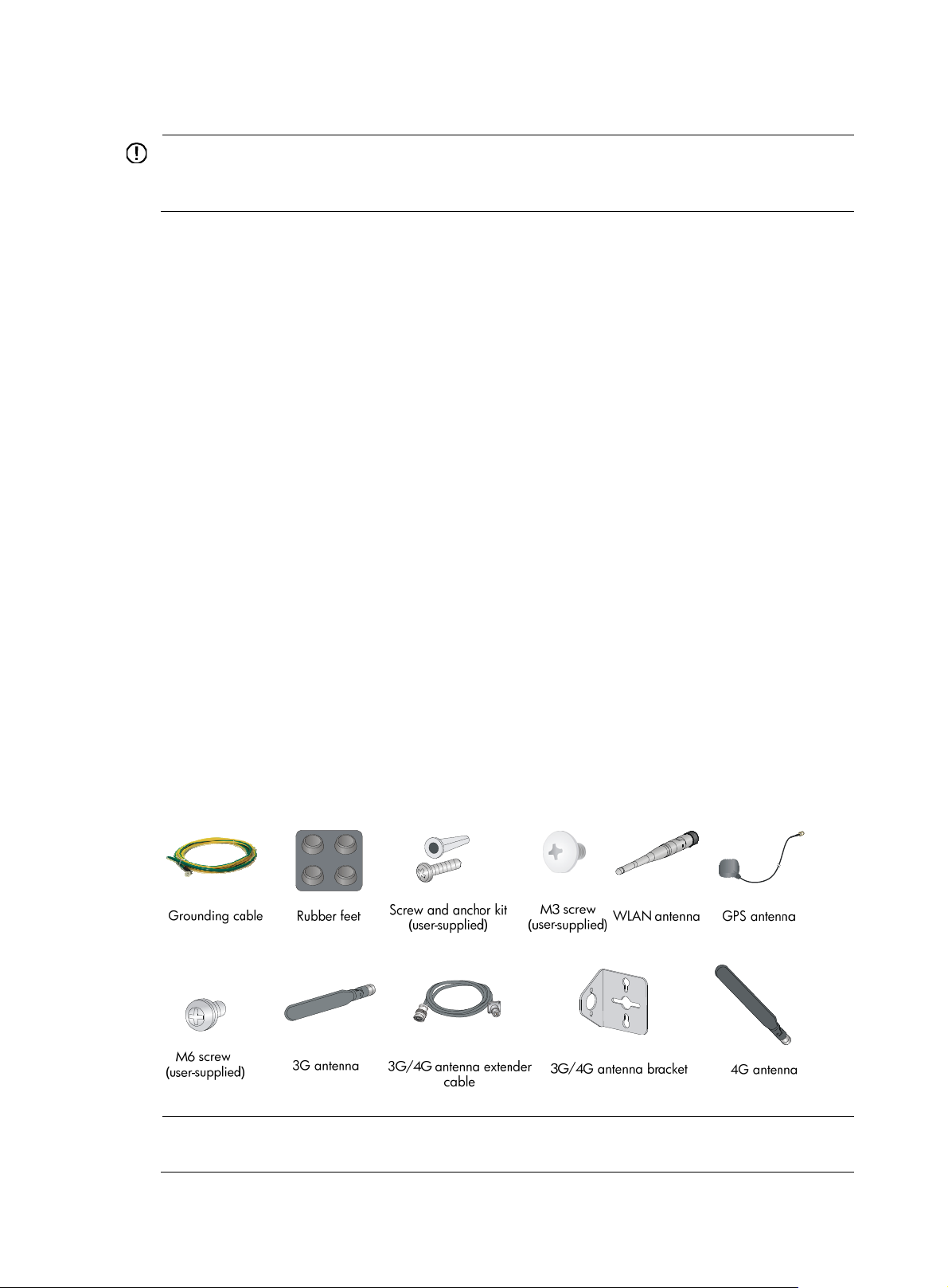
Figure 1 lists the installation accessories for the router.
Figure 1 Installation accessories
NOTE:
The type of the antenna that comes with the router depends on the router model.
3
Page 8

Pre-installation checklist
Item Requirements
• There is a minimum clearance of 10 cm (3.9 in) around
Ventilation
the router chassis intake and exhaust vents for heat
dissipation.
• The installation site ventilation system is adequate.
Temperature 0°C to 40°C (32°F to 104°F)
Relative humidity 5% to 90% (noncondensing)
Cleanness Dust concentration ≤ 3 × 10⁴ particles/m3
• The equipment and floor are correctly grounded.
• The equipment room is dust-controlled.
ESD prevention
• Humidity and temperature are maintained at acceptable
levels.
• Wear an ESD wrist strap when inspecting or handling a
circuit board.
• Take measures to protect the power system from the
power grid system.
Installation
site
EMI prevention
• Keep the protection ground of the router as far away from
the grounding device or lightning protection grounding
device as possible.
• Keep the router far away from radio transmitters, radar,
and high-frequency or high-voltage devices.
• Use electromagnetic shielding when necessary.
• The grounding cable of the chassis is grounded correctly.
• The grounding terminal of the AC power receptacle is
grounded correctly.
Lightning protection
• A port lightning arrester is installed. (Optional.)
• A power lightning arrester is installed. (Optional.)
• A signal lightning arrester is installed at the input end of
an external signal cable. (Optional.)
• Install a UPS.
Safety
precautions
Electricity safety
Workbench
• The router is far away from any sources of heat or moisture.
• The emergency power switch in the equipment room is identified and accessible.
• In case of emergency during operation, switch off the
external power switch.
• The workbench is stable.
• The workbench is grounded correctly.
Yes No
Installation
accessories
and tools
Reference
• Installation accessories supplied with the router are ready.
• User-supplied accessories and tools are ready.
• Documents shipped with the router are available.
• Online documents are available.
4
Page 9

W
g
Installing the router
ARNING!
To avoid injury, do not touch bare wires, terminals, or parts with high-voltage hazard signs.
IMPORTANT:
• The barcode on the router chassis contains product information that must be provided to HP Support
before you return a faulty router for service.
• Keep the tamper-proof seal on a mountin
chassis, contact HP for permission. Otherwise, HP shall not be liable for any consequence.
Installation prerequisites
• You have read "Preparing for installation" carefully.
• All requirements in "Preparing for installation" ar
Installation flowchart
You can install the router on a workbench or on a wall. Select an installation method according to the
installation environment, and follow the installation flowchart shown in Figure 2.
screw on the chassis cover intact, and if you want to open the
e met.
5
Page 10
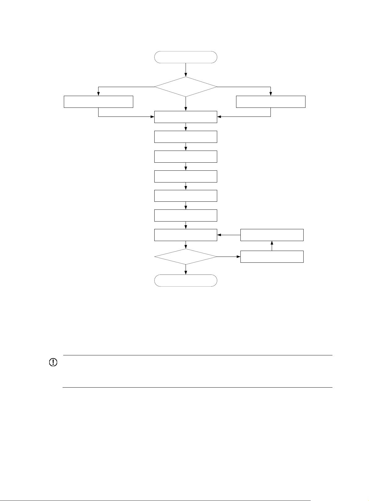
Figure 2 Installation flowchart
Start
Check the workbench
Mount the router on a
workbench
Install the router
Ground the router
Install antennas
Connect interface cables
Connect the router to a console
terminal
Connect the power adapter
Verify the installation
Power on the router
Yes
End
Install the router on a wall
Install wall-mounting screws
Troubleshoot the router
Power off the routerOperate correctly ?
No
Installing the router
Mounting the router on a workbench
IMPORTANT:
• Ensure good ventilation and 10 cm (3.9 in) of clearance around the chassis for heat dissipation.
• Avoid placing heavy objects on the router.
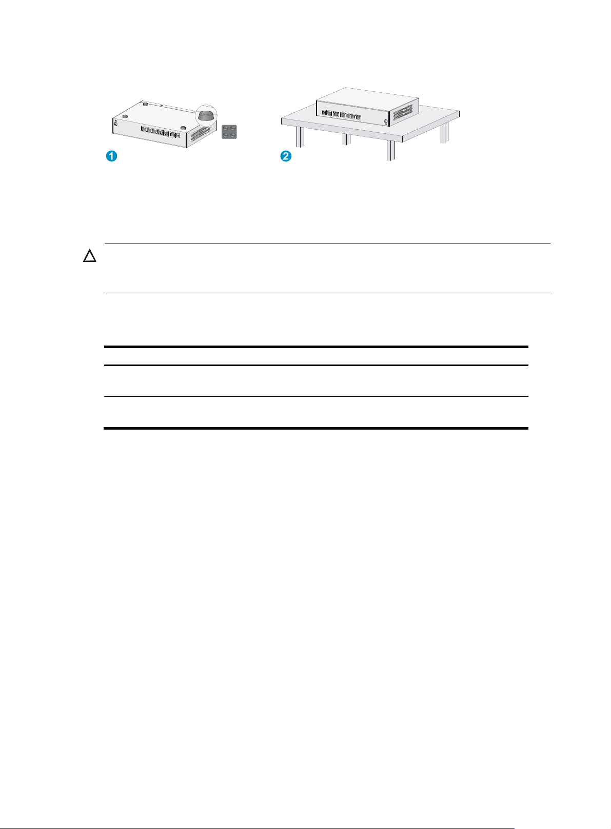
To mount the router on a workbench:
1. Make sure the workbench is clean, stable, and correctly grounded.
2. Place the router upside down on the workbench and attach the rubber feet to the four round holes
in the chassis bottom.
6
Page 11
W
Figure 3 Mounting the router on a workbench
Installing the router on a wall
CAUTION:
hen mounting the router on a wall, position the router so the network interfaces face downwards, and
the sides with ventilation openings are perpendicular to the ground, as shown in Figure 4.
To mount the router on a wall:
1. Mark the locations of the two mounting holes on the wall with the separations listed as follows:
Router model Separation
JG511A, JG512A, JH012A, JG513A, JG596A, JG665A, and
JG704A
JG514A, JG515A, JG531A, JG516A, JG517A, JG518A, JG519A,
JH013A, JG520A, and JG597A
180 mm (7.09 in)
240 mm (9.45 in)
The holes must be level (on the same horizontal line).
2. Drill two holes in the wall.
3. Following the marks, drill the two holes at least 22 mm (0.87 in) deep.
Verify that the holes are level.
4. Insert an anchor into each hole so it is flush with the wall surface.
5. Drive a screw into each anchor, keeping the screw heads protruding at least 1.5 mm (0.06 in)
from the wall.
6. Hang the router on the screws.
7
Page 12

W
g
Figure 4 Wall-mounting the router
Grounding the router
ARNING!
Connecting the router grounding cable correctly is crucial for protectin
Make sure the grounding resistance is less than 5 ohms.
You can ground the router with a grounding strip or to a buried grounding conductor.
Grounding the router with a grounding strip
1. Remove the grounding screw from the router chassis.
2. Put the ring terminal of the grounding cable on the grounding screw.
3. Use a screwdriver to fasten the grounding screw.
4. Attach the other end of the grounding cable to the grounding strip.
the router from lightning and EMI.
8
Page 13
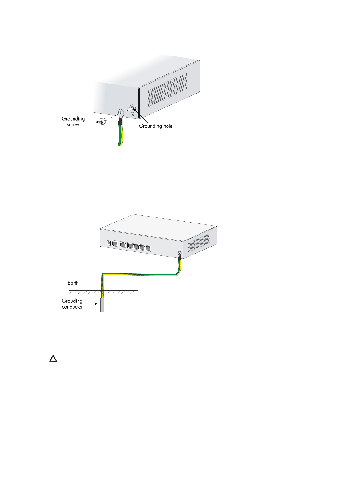
Figure 5 Connecting the grounding cable to the router
Grounding the router to a buried grounding conductor
If the installation site has no grounding strips but offers the option of grounding to earth, hammer a 0.5
m (1.64 ft) or longer angle iron or steel tube into the earth to serve as a grounding conductor, as shown
in Figure 6.
Figure 6 Grounding to
a conductor buried in the earth
Installing a standard 3G SIM card
CAUTION:
• Do not install or remove a standard 3G SIM card when the router is powered on.
• To avoid damage to the holder, do not use excessive strength when you install the standard 3G SIM
card.
The HP MSR93X routers support the following frequency ranges:
• 3G—800/850/900/1900/2100 MHz WCDMA/HSDPA/HSUPA/HSPA+
• 2G—850/900/1800/1900 MHz GSM/GPRS/EGPRS
To install a standard 3G SIM card:
9
Page 14
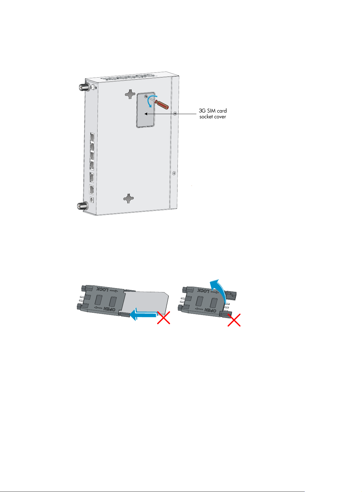
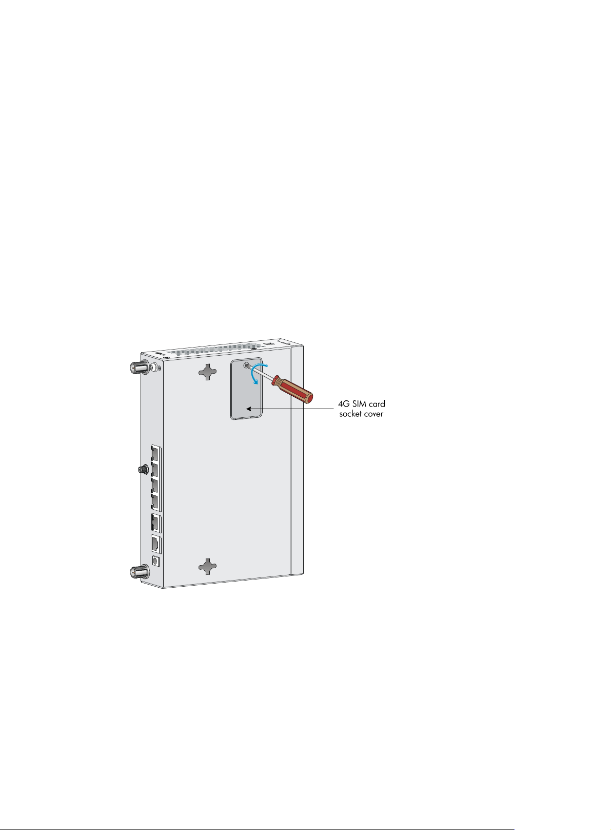
1. Use a screwdriver to loosen the screws on the 3G SIM card socket cover on the bottom of the
chassis, and remove the cover.
Figure 7 Removing the 3G SIM card socket cover
2. Push the 3G SIM card holder in the direction marked "OPEN" so the holder projects upwards.
Do not directly insert the standard 3G SIM card into the holder, or lift the holder.
Figure 8 illustrates the wron
g installation methods.
Figure 8 Wrong installation methods
3. Insert the standard 3G SIM card along the slide rails to the holder.
4. Put down the holder and push the holder in the direction marked "LOCK" to lock the card in
position.
10
Page 15
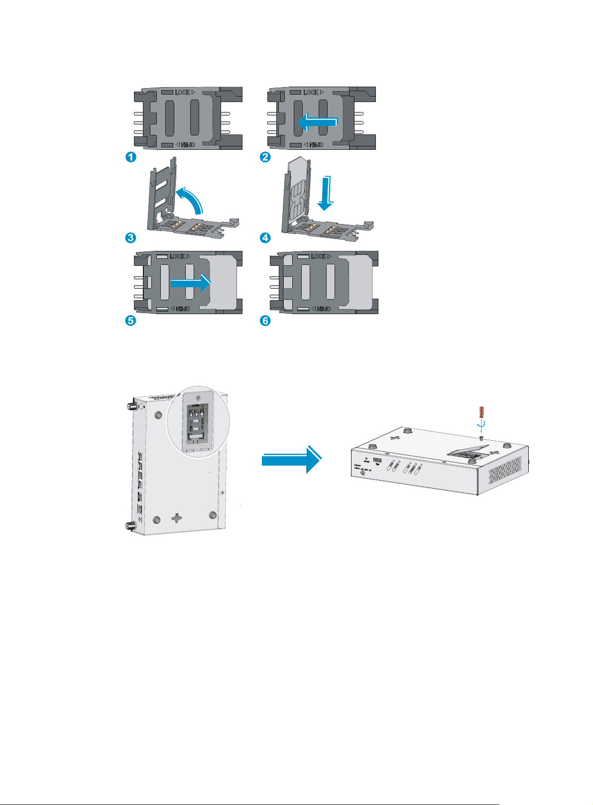
Figure 9 Installing the standard 3G SIM card
5. Position the socket cover and use a screwdriver to fasten the screws on the cover.
Figure 10 Installing the cover
Installing a 3G antenna
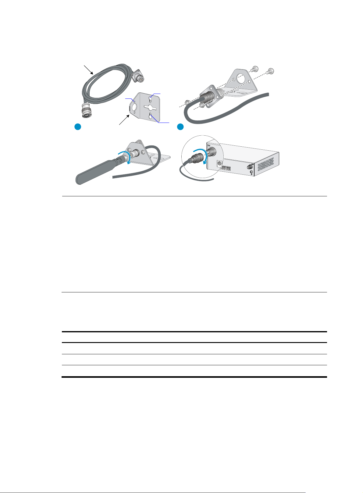
To install a 3G antenna:
1. Thread the male connector of the 3G cable through the hole on the bracket, and use screws (from
behind the bracket) to secure the male connector to the bracket.
2. Change the angle of the antenna orientation from vertical to horizontal.
3. Attach the antenna to the male connector of the cable.
4. Attach the female connector of the cable to the router.
11
Page 16
g
Figure 11 Installing a 3G antenna
3G/4G antenna
extension cable
M3
1 2
Antenna extension
cable bracket
M6
M2.9
NOTE:
• A 3G module is provided with a 3G antenna and a 3G extender cable. Connect the 3G antenna to the
port marked "MAIN" by using the 3G extender cable. Ensure a minimum of 25 cm (9.84 in) distance
between the 3G antenna and the chassis and between the 3G antenna and any other antenna installed
on or connected to the router.
• When a second 3G antenna is required, purchase the other 3G antenna and 3G extender cable
yourself. Attach the second 3G antenna to the port marked "DIV" if no antennas are installed on the
router or connect the second 3G antenna to the port marked "DIV" by usin
the 3G extender cable if the
router has antennas installed. Ensure a minimum of 25 cm (9.84 in) distance between the 3G antenna
(when the extender cable is used) and the chassis and between the 3G antenna and any other antenna
installed on or connected to the router.
Table 5 lists HP extender cables. You can use HP extender cables, but HP is not liable for any
consequences caused thereby.
Table 5 3G extender cables
J Number Extender Cable
JG522A HP MSR 2.8m Extender Cable
JG666A HP MSR 6m Extender Cable
JG667A HP MSR 15m Extender Cable
On a dual-3G JG531A router, the 3G SIM1 and 3G SIM2 cards are associated with the two antenna
connectors on the front and rear panels, respectively. Make sure you install the antennas at the correct
positions.
12
Page 17
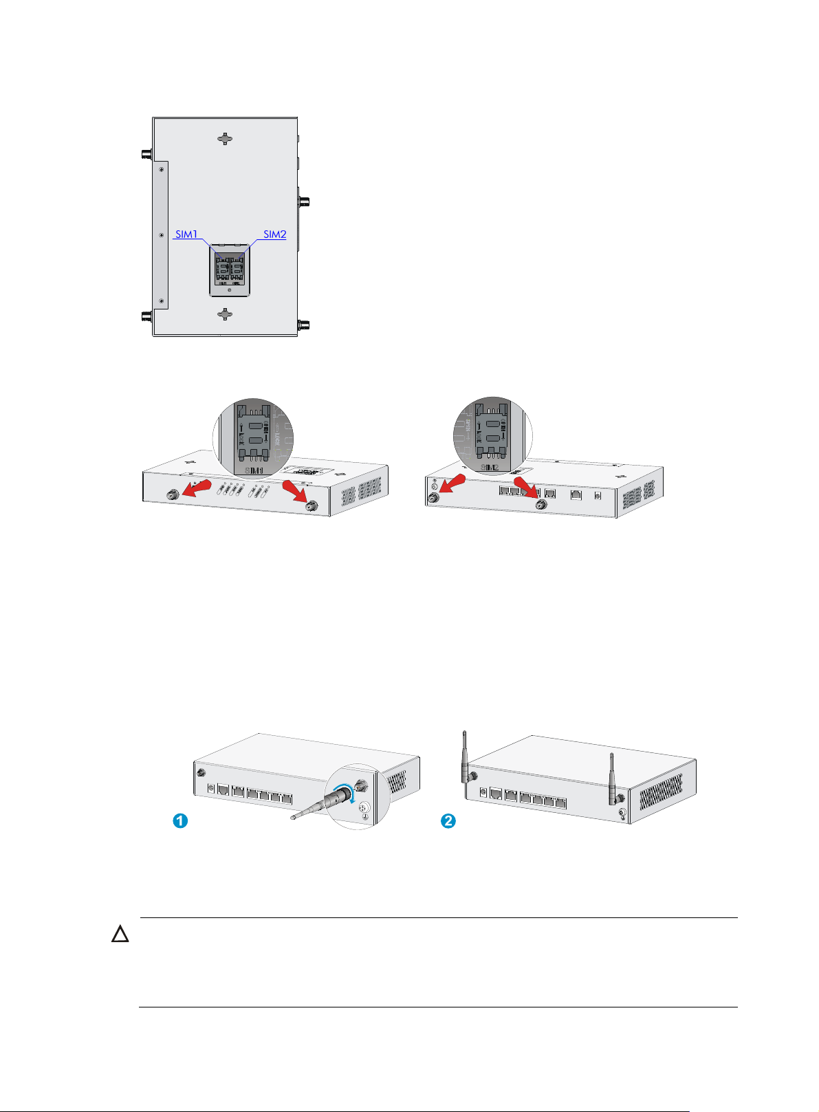
Figure 12 SIM card locations on a dual-3G JG531A router
Figure 13 SIM cards and antenna connectors
Installing WLAN antennas
1. Change the angle of the antenna orientation from vertical to horizontal.
2. Attach the antenna to the router, as shown in Figure 14. Avoid over
3. Install the other antenna in the same way.
Change the antenna orientation to vertical to achieve better signal coverage.
Figure 14 Installing WLAN antennas
Installing a standard 4G SIM card
-tightening.
CAUTION:
• Do not install or remove a standard 4G SIM card when the router is powered on.
• To avoid damage to the holder, do not use excessive strength when you install the standard 4G SIM
card.
13
Page 18
The JG596A router supports the following frequency ranges:
• 4G—700 MHz LTE
• 3G—800/1900 MHz CDMA
The JG704A router supports the following frequency ranges:
• 4G—700/1700/2100 MHz LTE
• 3G—800/850/1900/2100 MHz WCDMA/HSDPA/HSUPA/HSPA+/DC-HSPA+
• 2G—850/900/1800/1900 MHz GSM/GPRS/EDGE
The JG665A router supports the following frequency ranges:
• 4G—DD800/900/1800/2100/2600 MHz LTE
• 3G—900/2100 MHz WCDMA/HSDPA/HSUPA/HSPA+
• 2G—900/1800/1900 MHz GSM/GPRS/EDGE
To install a standard 4G SIM card:
1. Use a screwdriver to loosen the screws on the standard 4G SIM card socket cover on the bottom
of the chassis, and remove the cover.
Figure 15 Removing the 4G SIM card socket cover
2. Push the 4G SIM card holder in the direction marked "OPEN" so the holder projects upwards.
Do not directly insert the standard 4G SIM card into the holder, or lift the holder.
Figure 16 illu
strates the wrong installation methods.
14
Page 19
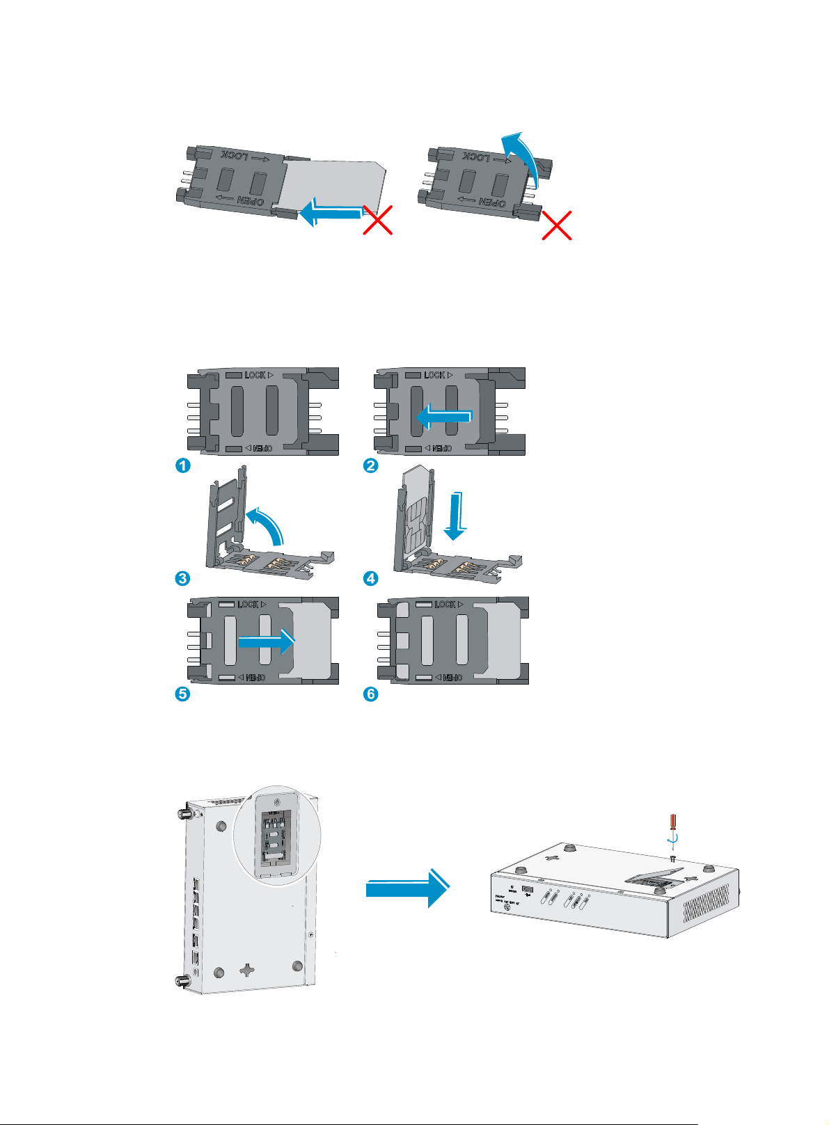
Figure 16 Incorrect installation methods
3. Insert the standard 4G SIM card along the slide rails to the holder.
4. Put down the holder and push the holder in the direction marked "LOCK" to lock the standard 4G
SIM card in position.
Figure 17 Installing the standard 4G SIM card
5. Position the socket cover and use a screwdriver to fasten the screws on the cover.
Figure 18 Installing the cover
15
Page 20

W
Installing a 4G antenna
CAUTION:
hen you install two 4G antennas on a JG704A router, connect one or both of the antennas to the router
by using antenna extender cables.
To install a 4G antenna:
1. Change the angle of the antenna orientation from vertical to horizontal.
2. Attach the antenna to the router, as shown in Figure 19. Avoid over
Change the antenna orientation to vertical to achieve better signal coverage.
Figure 19 Installing a 4G antenna
4G antenna
1 2
-tightening.
Installing a 3G/4G antenna extender cable to a 4G device
One 3G/4G antenna extender cable is provided with the JG704A router. No 3G/4G antenna extender
cable is provided with other router models. Purchase 3G/4G antenna extender cables as required.
To install a 3G/4G antenna extender cable to a 4G device:
1. Thread the male connector of the cable through the hole on the bracket, and use screws (from
behind the bracket) to secure the male connector to the bracket.
2. Change the angle of the antenna orientation from vertical to horizontal.
3. Attach the antenna to the male connector of the cable.
4. Attach the female connector of the cable to the router.
16
Page 21

Figure 20 Installing the 3G/4G antenna extender cable to a 4G device
Installing a GPS antenna
1. Attach one end of the antenna to the GPS antenna connector on the router, as shown in Figure 21.
Avoid over-tightening.
2. Attach the magnetic end of the antenna to a metal media near the router.
Figure 21 Installing a GPS antenna
JG704A router antenna installation instructions
When you install a 4G or GPS antenna to a JG704A router, follow these guidelines:
• Ensure a minimum distance of 25 cm (9.84 in) between the antenna and any other antenna on the
router.
• Ensure a minimum distance of 25 cm (9.84 in) between the GPS antenna or the 4G antenna (when
an extender cable is used) and the router.
17
Page 22

Only one 4G extender cable is provided with the router. Purchase another one yourself if you want to
install two 4G extender cables. Table 6 lists 4G
extender cables provided by HP. You can also use 4G
extender cables from other vendors, for any consequences resulting from which HP assumes no liabilities.
Table 6 HP 4G extender cables
J number HP 4G extender cable
JG522A HP MSR 2.8m Extender Cable
JG666A HP MSR 6m Extender Cable
JG667A HP MSR 15m Extender Cable
Figure 22 JG704A router antenna installation precautions
Connecting interface cables
This section uses the Ethernet cable for example.
Because fixed Ethernet ports support MDI/MDIX autosensing, you can use either a straight-through cable
or a crossover cable for connection.
To connect an Ethernet cable:
1. Connect one end of the cable to an Ethernet port on the router.
2. Connect the other end of the cable to the peer device.
3. Examine the port LED status. For more information, see "LED description."
Figure 23 Connecting th
e router to a computer
18
Page 23

W
Connecting the console cable and setting terminal parameters
Connecting the console cable
CAUTION:
hen using a console cable to connect a PC to the router, first connect the DB-9 end of the console cable
to the PC serial port, and then connect the RJ-45 connector of the console cable to the router console port.
To connect the console cable, as shown in Figure 24:
1. Select a console terminal, which can be an ASCII terminal with an RS232 serial port or a PC. (A
PC is more commonly used.)
2. Connect the DB-9 connector (female) of the console cable to the RS-232 serial port of the console
terminal and the RJ-45 connector to the console port of the router.
Figure 24 Connecting the console cable
Setting console terminal parameters
1. Select Start > All Programs > Accessories > Communications > HyperTerminal.
The Connection Description dialog box appears.
2. Enter the name of the new connection in the Name field and click OK.
19
Page 24

Figure 25 Connection description
3. Select the serial port to be used from the Connect using list, and click OK.
Figure 26 Setting the serial port used by the HyperTerminal connection
4. Set Bits per second to 9600, Data bits to 8, Parity to None, Stop bits to 1, and Flow control to None,
and click OK.
NOTE:
To restore the default settings, click Restore Defaults.
20
Page 25

Figure 27 Setting the serial port parameters
5. Select File > Properties in the HyperTerminal window.
Figure 28 HyperTerminal window
6. On the Settings tab, set the emulation to VT100 or Auto Detect, and click OK.
21
Page 26

Figure 29 Setting the terminal emulation parameters
Connecting the power adapter
The router's power adapter converts AC power to DC power, as follows:
• AC rated voltage range: 100 VAC to 240 VAC @ 50 Hz to 60 Hz
• DC Rated voltage: 12 VDC
To connect the power adapter, as shown in Figure 30:
1. Make sure the router i
2. Using the adapter's AC power cord, c
3. Connect the DC power cord connector on the power adapter to the DC power receptacle on the
router's panel.
s correctly grounded. For more information, see "Grounding the router."
onnect the power adapter to an AC power source.
22
Page 27

W
g
Figure 30 Connecting the power adapter
Verifying the installation
After you complete the installation, verify that:
• There is enough space around the router for heat dissipation.
• The router is mounted securely on the wall or on a sturdy workbench.
• Antennas, USB devices, and interface modules are installed correctly.
• The router and power module are grounded correctly.
• The power supply meets requirements.
• The router is connected correctly to the console terminal and other devices; parameters are
configured correctly on the console terminal.
Before starting up the router, set up the console terminal as described in "Connecting the console cable
and set
router.
ting terminal parameters." Then, power on the router and perform initial configuration for the
Powering on the router
ARNING!
Before powerin
case of an emergency.
• Switch on the power source.
• Turn on the power switch on the router.
on the router, locate the power source switch so that you can cut off power promptly in
Startup process
After power-on, the router initializes its memory, and then runs the extended BootWare. The console
terminal screen displays the following information:
System is starting...
Do you want to check SDRAM? [Y/N]
Booting Normal Extend BootWare
23
Page 28

The Extend BootWare is self-decompressing........................Done!
****************************************************************************
* *
* HP MSR931 BootWare, Version 1.01 *
* *
****************************************************************************
Copyright (c) 2010-2012 Hewlett-Packard Development Company, L.P.
Compiled Date : Sep 3 2012
CPU Type : P1016
CPU L1 Cache : 32KB
CPU L2 Cache : 256KB
CPU Clock Speed : 533MHz
Memory Type : DDR3 SDRAM
Memory Size : 256MB
Memory Speed : 667MHz
BootWare Size : 1024KB
Flash Size : 128MB
CPLD Version : 131.0
PCB Version : 3.0
BootWare Validating...
Press Ctrl+B to enter extended boot menu...
Starting to get the main application file--flash:/mainmsr93x.bin!...........
............................................................................
The main application file is self-decompressing.............................
............................................................................
........................Done!
System application is starting..................................................
User interface aux0 is available.
Press ENTER to get started.
Press Enter and the system displays the following prompt:
<HP>
This prompt indicates that the router has entered user view and is ready to configure.
Power-on check
After powering on the router, check the following items:
• The LEDs on the front panel are normal, as described in "LED description."
• The console terminal displays information correctly. You can see the startup window on the local
console terminal. For more information, see "Startup process."
• After completing the POST, the system prompts you to press Enter. When the command line prompt
appears, the router is ready to configure.
24
Page 29

Configuring basic settings for the router
After the router is powered on for the first time, configure basic settings for the router. For more
information, see HP MSR Routers Fundamentals Configuration Guide and HP MSR Routers Fundamentals
Command Reference.
25
Page 30

g
Troubleshooting
IMPORTANT:
• The barcode on the router chassis contains product information that must be provided to HP Support
before you return a faulty router for service.
• Keep the tamper-proof seal on a mountin
chassis, contact HP for permission. Otherwise, HP shall not be liable for any consequence.
screw on the chassis cover intact, and if you want to open the
Power supply failure
If the router cannot be powered on and LEDs on the front panel are off, it indicates that the power supply
is faulty.
To troubleshoot the power supply:
1. Power off the router.
2. Verify that the router's power cords are connected firmly.
3. Verify that the power source is operating correctly.
4. Determine if the power cord is damaged.
If the problem persists, contact HP Support.
System configuration problems
If the configuration environment setup is correct, the console terminal displays boot information when the
router is powered on. If the setup is incorrect, the console terminal displays nothing or garbled text.
No terminal display
If the console terminal displays nothing when the router is powered on, verify the following items:
• The power supply system is operating correctly.
• The console cable is connected correctly.
• The console cable is connected to the serial port that is configured for the console terminal.
• The console terminal properties are set to the following: Bits per second: 9600, Data bits: 8, Parity:
None, Stop bits: 1, Flow control: None, and Terminal Emulation: VT100.
• The console cable is operating correctly.
Garbled terminal display
If terminal display is garbled, make sure the Data bits field for the console terminal is set to 8. If the Data
bits field is set to 5 or 6, the console terminal will display garbled characters.
26
Page 31

No response from the serial port
If the serial port does not respond, verify that the serial cable is in good condition and the serial port
settings are correct.
Password loss
User password loss
If you lose your password, you cannot enter the system. In this case, you can boot the system by ignoring
the system configuration.
To solve the user password loss:
1. Enter the main BootWare menu, and select 6 to boot the system by ignoring the system
configuration.
The system prompts the following:
Flag Set Success.
The output shows that the setting succeeded.
2. When the main BootWare menu appears again, and select 0 to reboot the system.
System is rebooting now.
System start booting...
Booting Normal Extend BootWare....
3. Set a new password in system view after the system reboots. The console port uses password
authentication, and the password is set to 123456 and stored in plain text.
<HP> system-view
[HP] user-interface console 0
[HP-ui-console0] authentication-mode password
[HP-ui-console0] set authentication password simple 123456
When you set the password by using the set authentication password { cipher | simple } password
command, note the following:
{ If you specify the cipher keyword, the password is stored in cipher text. You cannot view the
password by using the display current-configuration command.
{ If you specify the simple keyword, the password is stored in plain text. You can use the display
current-configuration command to view the password in the current configuration.
4. After modifying the user password, save it by executing the save command. HP recommends that
you save the modifications as the default configuration file.
[HP] save
After reboot, the system uses the initial default configuration, but keeps the original configuration file in
storage. You can restore the original configuration by using the display saved-configuration command to
display the configuration, and then copying and executing the configuration.
Super password loss
The super password provides access to four super levels, enabling you to perform higher-level
operations.
27
Page 32

To recover from super password loss:
1. On the main BootWare menu, select 8.
This setting (Clear Super Password) is valid only for the first reboot of the router. The super
password is restored after the second reboot.
========================<EXTEND-BOOTWARE MENU>========================
|<1> Boot System |
|<2> Enter Serial SubMenu |
|<3> Enter Ethernet SubMenu |
|<4> File Control |
|<5> Modify BootWare Password |
|<6> Skip Current System Configuration |
|<7> BootWare Operation Menu |
|<8> Clear Super Password |
|<9> Storage Device Operation |
|<0> Reboot |
======================================================================
Enter your choice(0-9):8
The following output indicates that you have successfully cleared the super password.
Clear Application Password Success!
2. Exit the menu and reboot the router.
The super password is cleared. You can enter system view.
3G/4G SIM card and 3G/4G antenna failures
When the LEDs on the front panel indicate abnormal state of the 3G/4G SIM card and 3G/4G antenna,
verify the following items:
• The SIM card has been correctly installed and makes good contact with the card socket.
• The SIM card matches the built-in module.
• The antenna is correctly installed.
• The SIM card, card socket, and antenna are in good condition.
• The network provided by NSP is running correctly.
If the problem still exists, contact HP Support.
Restoring the factory settings
Scenario 1
Symptom
When you replace the router, the router password is lost. As a result, you cannot log in to the router and
do not know the router configuration.
28
Page 33

Solution
Because the router is replaced, you do not need to save the configuration of the router. In this case, you
can press the Reset button for more than 4 seconds to reboot the router and restore the factory settings.
Then, you can use the username and password shipped with the router to log in to the router.
When the router configuration must be saved and you have a console cable, you can log in to the router
from the BootWare menu. For more information, see "User password loss."
Scenario 2
Symptom
After the configuration is modified, the network connectivity is lost. When you check the configuration,
the configuration is very complicated and it is hard to locate the errors. In this case, you must configure
the router again.
Solution
If you have not saved any configuration, you can reboot the router through pressing the Reset button for
a short time or power off the router.
If you have saved the configuration, delete the configuration file at the CLI, and press the Reset button to
restore the factory settings.
Scenario 3
Symptom
The router crashes.
Solution
Press the Reset button for a short time to reboot the router.
Reset button usage guidelines
The router provides the Reset button. You can use the button to reboot the system or restore the factory
settings.
1. Press the Reset button for a short time to reboot the router.
2. Press the Reset button for more than 4 seconds to reboot the router and restore the factory settings.
29
Page 34

Appendix A Chassis views and technical specifications
The MSR93X routers include the following models: JG511A, JG512A, JH012A, JG513A, JG514A,
JG515A, JG531A, JG516A, JG517A, JG518A, JG519A, JH013A, JG520A, JG596A, JG665A, JG704A,
and JG597A.
Chassis views
The figures in this appendix are for illustration only.
JG511A
Figure 31 Front view
(1) USB port (2) Reset button
Figure 32 Rear view
(1) Power adapter port (2) Console/AUX port
(4) Ethernet LAN ports (GE1 to GE4) (5) Grounding screw
(3) Ethernet WAN port (GE0)
30
Page 35

JG512A
Figure 33 Front view
(1) USB port (2) Reset button
Figure 34 Rear view
2
1
3 4 5 6
(1) WLAN antenna connector (2) Power adapter port (3) Console/AUX port
(4) Ethernet WAN port (GE0) (5) Ethernet LAN ports (GE1 to GE4)
(7) Grounding screw
JH012A
Figure 35 Front view
(1) USB port (2) Reset button
7
(6) WLAN antenna connector
31
Page 36

Figure 36 Rear view
(1) WLAN antenna connector (2) Power adapter port (3) Console/AUX port
(4) Ethernet WAN port (GE0) (5) Ethernet LAN ports (GE1 to GE4)
(7) Grounding screw
JG513A
Figure 37 Front view
2
1
3 4 5 6
7
(6) WLAN antenna connector
(1) USB port (2) Reset button
Figure 38 Rear view
(1) 3G antenna auxiliary connector (DIV) (2) Power adapter port
(4) Ethernet WAN port (GE0) (5) Ethernet LAN ports (GE1 to
GE4 )
(7) Grounding screw
(3) Console/AUX port
(6) 3G antenna main
connector (MAIN)
32
Page 37

JG514A
Figure 39 Front view
(1) USB port (2) Reset button
Figure 40 Rear view
(1) Synchronous/asynchronous serial
port (Serial0)
(4) Grounding screw (5) Power adapter port
JG515A
Figure 41 Front view
1
5
6
2 3 4
(2) Ethernet WAN port (GE0) (3) Ethernet LAN ports (GE1 to
GE4)
(6) Console/AUX port
(1) 3G antenna auxiliary connector (DIV) (2) USB port
(3) Reset button (4) 3G antenna main connector (MAIN)
33
Page 38

Figure 42 Rear view
(1) Synchronous/asynchronous serial
port (Serial0)
(4) Grounding screw (5) Power adapter port (6) Console/AUX port
JG531A
Figure 43 Front view
1
5
6
2
3 4
(2) Ethernet WAN port (GE0) (3) Ethernet LAN ports (GE1 to
GE4)
1 2 3 4
(1) 3G antenna auxiliary connector (DIV1)
(3) Reset button (4) 3G antenna main connector (MAIN1)
(2) USB port
Figure 44 Rear view
(1) Synchronous/asynchronous serial
port (Serial0)
(4) Ethernet LAN ports (GE1 to GE4) (5) 3G antenna main
(7) Power adapter port (8) Console/AUX port
(2) Ethernet WAN port (GE0) (3) 3G antenna auxiliary
connector (DIV2)
(6) Grounding screw
connector (MAIN2)
34
Page 39

JG516A
Figure 45 Front view
(1) USB port (2) Reset button
Figure 46 Rear view
(1) G.SHDSL port 0 (2) Ethernet WAN port (GE0) (3) Ethernet LAN ports (GE1 to GE4)
(4) Grounding screw (5) Power adapter port
JG517A
Figure 47 Front view
(1) 3G antenna auxiliary connector (DIV)
(3) Reset button (4) 3G antenna main connector (MAIN)
(6) Console/AUX port
(2) USB port
35
Page 40

Figure 48 Rear view
(1) G.SHDSL port 0
(4) Grounding screw (5) Power adapter port (6) Console/AUX port
JG518A
Figure 49 Front view
(1) USB port (2) Reset button
Figure 50 Rear view
(2) Ethernet WAN port (GE0)
(3) Ethernet LAN ports (GE1 to GE4)
(1) ADSL port 0 (2) Ethernet WAN port (GE0)
(4) Grounding screw (5) Power adapter port (6) Console/AUX port
36
(3) Ethernet LAN ports (GE1 to GE4)
Page 41

JG519A
Figure 51 Front view
(1) WLAN antenna connector (2) USB port
(3) Reset button (4) WLAN antenna connector
Figure 52 Rear view
(1) ADSL port 0 (2) Ethernet WAN port (GE0)
(4) Grounding screw (5) Power adapter port
JH013A
Figure 53 Front view
(1) WLAN antenna connector (2) USB port
(3) Reset button (4) WLAN antenna connector
(3) Ethernet LAN ports (GE1 to GE4)
(6) Console/AUX port
37
Page 42

Figure 54 Rear view
(1) ADSL port 0 (2) Ethernet WAN port (GE0)
(4) Grounding screw (5) Power adapter port (6) Console/AUX port
JG520A
Figure 55 Front view
(1) 3G antenna auxiliary connector (DIV)
(3) Reset button (4) 3G antenna main connector (MAIN)
Figure 56 Rear view
(3) Ethernet LAN ports (GE1 to GE4)
1 2 3 4
(2) USB port
(1) ADSL port 0 (2) Ethernet WAN port (GE0) (3) Ethernet LAN ports (GE1 to GE4)
(4) Grounding screw (5) Power adapter port (6) Console/AUX port
38
Page 43

JG596A
Figure 57 Front view
(1) USB port (2) Reset button
Figure 58 Rear view
(1) 4G antenna connector M1 (2) Ethernet WAN port (GE0) (3) Ethernet LAN ports (GE1 to GE4)
(4) GPS antenna connector (5) 4G antenna connector M0 (6) Grounding screw
(7) Power adapter port (8) Console/AUX port
JG665A
Figure 59 Front view
1
2 3
4
5
6
7
8
(1) USB port (2) Reset button
39
Page 44

Figure 60 Rear view
(1) 4G antenna connector M1 (2) Ethernet WAN port (GE0)
(4) GPS antenna connector (5) 4G antenna connector M0 (6) Grounding screw
(7) Power adapter port (8) Console/AUX port
JG704A
Figure 61 Front view
(1) USB port (2) Reset button
Figure 62 Rear view
(3) Ethernet LAN ports (GE1 to GE4)
(1) 4G antenna connector M1 (2) Ethernet WAN port (GE0) (3) Ethernet LAN ports (GE1 to GE4)
(4) GPS antenna connector (5) 4G antenna connector M0 (6) Grounding screw
(7) Power adapter port (8) Console/AUX port
40
Page 45

JG597A
Figure 63 JG597A front view
(1) WLAN antenna connector (2) USB port
(3) Reset button (4) WLAN antenna connector
Figure 64 JG597A rear view
(1) ADSL port 0 (2) ISDN port BRIS/T0
(4) Ethernet LAN ports (GE1 to GE4) (5) Grounding screw
(7) Console/AUX port
Technical specifications
Item
Console/AUX
port
USB port 1
GE WAN port 1
GE LAN port 4
Serial port N/A N/A N/A 1 1 1 N/A N/A
G.SHDSL port N/A N/A N/A N/A N/A N/A 1 1
JG511
A
1
JG512
A/JH01
2A
JG513A JG514A JG515A JG531A JG516
(3) Ethernet WAN port (GE0)
(6) Power adapter port
A
JG517A
Built-in 3G
module
N/A N/A 1 N/A 1 2 N/A 1
41
Page 46

Item
WLAN
module
Memory
Flash 128 MB
Dimensions (H
× W × D)
(excluding
rubber feet
and mounting
brackets)
Weight
AC power
adapter
Max. AC
power
Operating
temperature
JG511
A
N/A 1 N/A N/A N/A N/A N/A N/A
256 MB DDR III
43.6 × 230 × 160 mm (1.72 ×
9.06 × 6.30 in)
1.0 kg
(2.20 lb)
Rated input voltage: 100 VAC to 240 VAC @ 50 Hz or 60 Hz
24 W
0°C to 40°C (32°F to 104°F)
JG512
A/JH01
2A
1.1 kg
(2.43 lb)
JG513A JG514A JG515A JG531A JG516
A
44.2 × 300 × 200 mm (1.74 × 11.81 × 7.87 in)
1.1 kg
(2.43 lb)
1.6 kg
(3.53 lb)
1.6 kg
(3.53 lb)
1.6 kg
(3.53 lb)
1.6 kg
(3.53 lb)
JG517A
1.6 kg
(3.53 lb)
Relative
humidity
(non-condensi
ng)
5% to 90%
JG519A
Item JG518A
/JH013
JG520A JG597A JG596A JG665A JG704A
A
Console/AUX port 1
USB port 1
GE WAN port 1
GE LAN port 4
ADSL port 1 1 1 1 N/A N/A N/A
ISDN port N/A N/A N/A 1 N/A N/A N/A
Built-in 3G module N/A N/A 1 N/A N/A N/A N/A
Built-in 4G module N/A N/A N/A N/A 1 1 1
WLAN module N/A 1 N/A 1 1 1 1
Memory 256 MB DDR III
Flash 128 MB
Dimensions (H × W
× D) (excluding
rubber feet and
mounting brackets)
44.2 × 300 × 200 mm (1.74 × 11.81 × 7.87 in)
42
43.6 x 230 x 160 mm (1.72 x 9.06
x 6.30 in)
Page 47

p
p
JG519A
Item JG518A
/JH013
JG520A JG597A JG596A JG665A JG704A
A
Weight
AC power adapter Rated input voltage: 100 VAC to 240 VAC @ 50 Hz or 60 Hz
Max. AC power
Operating
temperature
Relative humidity
(non-condensing)
1.6 kg (3.53 lb) 1.1 kg (2.43 lb)
24 W
0°C to 40°C (32°F to 104°F)
5% to 90%
Antenna specifications
Table 7 4G antenna specifications
Item S
Frequency range 698-960 MHz to 1710-2170 MHz
Voltage standing wave ratio
(VSWR)
Input impedance 50 ohms
Gain 2 dBi
ecification
< 2.5
Max power consumption 5 W
Input interface TNC male
Length 21.4 cm (8.43 in)
Color Black
Weight 50 g (1.76 oz)
Operating temperature –40°C to +85°C (–40°F to +185°F)
Table 8 3G antenna specifications
Item S
Frequency range 806-960 MHz to 1710-2170 MHz
Voltage standing wave ratio
(VSWR)
Input impedance 50 ohms
Gain 0 dBi
Max power consumption 25 W
Input interface TNC male
Length 254 mm (10 in)
ecification
< 2.5
Color Gray
43
Page 48

p
Item Specification
Weight 45 g (1.59 oz)
Operating temperature –30°C to +70°C (–22°F to +158°F)
Table 9 WLAN antenna specifications
Item S
Frequency range 2.4 GHz to 2.5 GHz
Voltage standing wave ratio
(VSWR)
Input impedance 50 ohms
Gain 2 dBi
Max power consumption 1 W
Input interface RSMA
Length 115 mm (4.53 in)
Color Black
Weight 25 g (0.88 oz)
Operating temperature –10°C to +60°C (14°F to 140°F)
ecification
1.92:1
44
Page 49

Appendix B LEDs
LEDs
JG511A
Figure 65 Front panel LEDs
(1) System status LED (SYS) (2) Network status LED (INTERNET) (3) VPN status LED (VPN)
Figure 66 Rear panel LEDs
(1) GE port status LED (yellow) (2) GE port status LED (green)
JG512A
Figure 67 Front panel LEDs
(1) System status LED (SYS) (2) Network status LED (INTERNET)
(3) VPN status LED (VPN) (4) WLAN status LED (WLAN)
45
Page 50

Figure 68 Rear panel LEDs
(1) GE port status LED (yellow) (2) GE port status LED (green)
JH012A
Figure 69 Front panel LEDs
2
1
2
1
(1) System status LED (SYS) (2) Network status LED (INTERNET)
(3) VPN status LED (VPN) (4) WLAN status LED (WLAN)
Figure 70 Rear panel LEDs
2
1
2
1
(1) GE port status LED (yellow) (2) GE port status LED (green)
46
Page 51

JG513A
Figure 71 Front panel LEDs
(1) System status LED (SYS) (2) Network status LED (INTERNET)
(3) 3G status LED (WWAN) (4) Received 3G signal strength indication LED (RSSI)
Figure 72 Rear panel LEDs
(1) GE port status LED (yellow) (2) GE port status LED (green)
JG514A
Figure 73 Front panel LEDs
(3) VPN status LED (VPN)
2
1
2
1
2
1 3
(1) System status LED (SYS) (2) Network status LED (INTERNET)
47
(3) VPN status LED (VPN)
Page 52

Figure 74 Rear panel LEDs
(1) GE port status LED (yellow) (2) GE port status LED (green)
(3) Serial port data transmission status LED (ACT)
JG515A
Figure 75 Front panel LEDs
(4) Serial port link status LED (LINK)
(1) System status LED (SYS) (2) Network status LED (INTERNET)
(3) 3G status LED (WWAN) (4) Received 3G signal strength indication LED (RSSI)
(3) VPN status LED (VPN)
Figure 76 Rear panel LEDs
(1) GE port status LED (yellow) (2) GE port status LED (green)
(3) Serial port data transmission status LED (ACT) (4) Serial port link status LED (LINK)
48
Page 53

JG531A
Figure 77 Front panel LEDs
(1) System status LED (SYS) (2) Network status LED (INTERNET) (3) VPN status LED (VPN)
(4) 3G status LED (WWAN) (5) Received 3G signal strength indication LED (RSSI)
Figure 78 Rear panel LEDs
4
3 4
2
1
5
5
(1) GE port status LED (yellow) (2) GE port status LED (green)
(3) Serial port data transmission status LED (ACT) (4) Serial port link status LED (LINK)
JG516A
Figure 79 Front panel LEDs
(1) System status LED (SYS) (2) Network status LED (INTERNET) (3) VPN status LED (VPN)
49
Page 54

Figure 80 Rear panel LEDs
(1) GE port status LED (yellow) (2) GE port status LED (green) (3) G.SHDSL port status LED
JG517A
Figure 81 Front panel LEDs
(1) System status LED (SYS) (2) Network status LED (INTERNET)
(4) 3G status LED (WWAN) (5) Received 3G signal strength indication LED (RSSI)
(3) VPN status LED (VPN)
Figure 82 Rear panel LEDs
2
1 2
3
(1) GE port status LED (yellow) (2) GE port status LED (green)
1
(3) G.SHDSL port status LED
50
Page 55

JG518A
Figure 83 Front panel LEDs
213
(1) System status LED (SYS) (2) Network status LED (INTERNET)
Figure 84 Rear panel LEDs
(1) GE port status LED (yellow) (2) GE port status LED (green)
JG519A
Figure 85 Front panel LEDs
(3) VPN status LED (VPN)
(3) ADSL port status LED
(1) System status LED (SYS) (2) Network status LED (INTERNET)
(3) VPN status LED (VPN) (4) WLAN status LED (WLAN)
51
Page 56

Figure 86 Rear panel LEDs
(1) GE port status LED (yellow) (2) GE port status LED (green)
JH013A
Figure 87 Front panel LEDs
(1) System status LED (SYS) (2) Network status LED (INTERNET)
(3) VPN status LED (VPN) (4) WLAN status LED (WLAN)
Figure 88 Rear panel LEDs
(3) ADSL port status LED
(1) GE port status LED (yellow) (2) GE port status LED (green)
52
(3) ADSL port status LED
Page 57

JG520A
Figure 89 Front panel LEDs
(1) System status LED (SYS) (2) Network status LED (INTERNET)
(4) 3G status LED (WWAN) (5) Received 3G signal strength indication LED (RSSI)
Figure 90 Rear panel LEDs
(1) GE port status LED (yellow) (2) GE port status LED (green)
JG596A
Figure 91 Front panel LEDs
(3) VPN status LED (VPN)
(3) ADSL port status LED
(1) System status LED (SYS) (2) Network status LED (INTERNET) (3) VPN status LED (VPN)
(4) GPS status LED (GPS) (5) 4G status LED (WWAN) (6) Received 4G signal strength
53
indication LED (RSSI)
Page 58

Figure 92 Rear panel LEDs
(1) GE port status LED (yellow) (2) GE port status LED (green)
JG665A
Figure 93 Front panel LEDs
(1) System status LED (SYS) (2) Network status LED (INTERNET)
(4) GPS status LED (GPS) (5) 4G status LED (WWAN) (6) Received 4G signal strength
(3) VPN status LED (VPN)
indication LED (RSSI)
Figure 94 Rear panel LEDs
(1) GE port status LED (yellow) (2) GE port status LED (green)
54
Page 59

JG704A
Figure 95 Front panel LEDs
(1) System status LED (SYS) (2) Network status LED (INTERNET) (3) VPN status LED (VPN)
(4) GPS status LED (GPS) (5) 4G status LED (WWAN) (6) Received 4G signal strength
Figure 96 Rear panel LEDs
indication LED (RSSI)
(1) GE port status LED (yellow) (2) GE port status LED (green)
JG597A
Figure 97 Front panel LEDs
(1) System status LED (SYS) (2) Network status LED (INTERNET)
(3) VPN status LED (VPN) (4) WLAN status LED (WLAN)
3 4
2
1
55
Page 60

Figure 98 Rear panel LEDs
(1) GE port status LED (yellow) (2) GE port status LED (green) (3) ISDN link status LED (ACT)
(4) ISDN B1 channel link status LED
(B1)
LED description
(5) ADSL port status LED (6) ISDN B2 channel link status LED
(B2)
LED Location Status
Off
Steady green The SDRAM is performing self-test.
Flashing green
(8 Hz)
System status
LED (SYS)
Network status
LED (INTERNET)
VPN status LED
(VPN)
Front panel
Front panel
Front panel
Flashing green
(1 Hz)
Flashing yellow
(1 Hz)
Flashing yellow
(8 Hz)
Steady yellow The system software image does not exist.
Off No PPP link is present.
Steady green A minimum of one PPP link is present.
Off No IPsec VPN tunnel is present.
Steady green A minimum of one IPsec VPN tunnel is present.
Off No link is present or no network is available.
Description
No power input, or exceptions have occurred on the
MPU.
The system software image is being copied and
decompressed.
Comware has started with the configuration file and
the router has booted up.
The SDRAM has failed the self-test.
The extended segment does not exist.
Steady green
3G status LED
(WWAN)
Front panel
Flashing green
(8 Hz)
Steady yellow
Flashing yellow
(8 Hz)
56
The router has been connected to the wireless
network and is operating in 3G mode.
Data is being received or transmitted. The router is
operating in 3G mode.
The router has been connected to the wireless
network and is operating in 2G mode.
Data is being received or transmitted. The router is
operating in 2G mode.
Page 61

LED Location Status
Received 3G
signal strength
indication LED
(RSSI)
4G status LED
(WWAN)
Received 4G
signal strength
indication LED
(RSSI)
Front panel
Front panel
Front panel
Off Weak or no signal.
Steady green Strong signal.
Flashing green
(8 Hz)
Off No link is present or a 2G network is available.
Steady green
Flashing green
(8 Hz)
Steady yellow
Flashing yellow
(8 Hz)
Off Weak or no signal.
Steady green Strong signal.
Flashing green
(8 Hz)
Description
Middle or low signal.
The router has been connected to the wireless
network and is operating in 4G mode.
Data is being received or transmitted. The router is
operating in 4G mode.
The router has been connected to the wireless
network and is operating in 3G mode.
Data is being received or transmitted. The router is
operating in 3G mode.
Middle or low signal.
WLAN status
LED (WLAN)
GE port status
LED
G.SHDSL port
status LED
ADSL port status
LED
Front panel
Rear panel
Rear panel
Rear panel
Off The link is idle.
Flashing green Data is being transmitted or received on the link.
Steady green The WLAN-radio interface is up.
Off No link is present.
Steady green A 1000 Mbps link is present.
Flashing green Data is being received or transmitted at 1000 Mbps.
Steady yellow A 10/100 Mbps link is present.
Flashing yellow
Off No carrier signal is received.
Steady green A carrier signal has been received.
Flashing green
(8 Hz)
Flashing green
(1 Hz)
Off No ADSL link is present.
Steady green An ADSL link is present.
Flashing green
(8 Hz)
Data is being received or transmitted at 10/100
Mbps.
Data is being received or transmitted.
Link negotiation is in progress.
The ADSL link is in synchronization progress.
Flashing green
(4 Hz)
57
Data is being received or transmitted on the ADSL
link.
Page 62

LED Location Status
Steady green The ISDN link has been activated.
ISDN link status
LED (ACT)
ISDN B1
channel link
status LED (B1)
ISDN B2
channel link
status LED (B2)
Serial port link
status LED (LINK)
Serial port data
transmission
status LED (ACT)
Rear panel
Rear panel
Rear panel
Rear panel
Rear panel
Flashing green
(8 Hz)
Off
Flashing green
(8 Hz)
Off
Flashing green
(8 Hz)
Off
Off No link is present.
Steady green A link is present.
Off No data is being received or transmitted.
Flashing yellow Data is being received or transmitted.
Description
The ISDN link is being activated.
The ISDN link is not activated or no ISDN link is
present.
Data is being received or transmitted on the B1
channel.
No data is being received or transmitted on the B1
channel.
Data is being received or transmitted on the B2
channel.
No data is being received or transmitted on the B2
channel.
58
Page 63

Support and other resources
Contacting HP
For worldwide technical support information, see the HP support website:
http://www.hp.com/support
Before contacting HP, collect the following information:
• Product model names and numbers
• Technical support registration number (if applicable)
• Product serial numbers
• Error messages
• Operating system type and revision level
• Detailed questions
Subscription service
HP recommends that you register your product at the Subscriber's Choice for Business website:
http://www.hp.com/go/wwalerts
After registering, you will receive email notification of product enhancements, new driver versions,
firmware updates, and other product resources.
Related information
Documents
To find related documents, browse to the Manuals page of the HP Business Support Center website:
http://www.hp.com/support/manuals
• For related documentation, navigate to the Networking section, and select a networking category.
• For a complete list of acronyms and their definitions, see HP FlexNetwork Technology Acronyms.
Websites
• HP.com http://www.hp.com
• HP Networking http://www.hp.com/go/networking
• HP manuals http://www.hp.com/support/manuals
• HP download drivers and software http://www.hp.com/support/downloads
• HP software depot http://www.software.hp.com
• HP Education http://www.hp.com/learn
59
 Loading...