

Page 1

HP MSM775 zl Controller Installation Guide
Abstract
This document describes how to install and initially configure the MSM775 zl Premium Controller (J9840A), hereafter referred
to as controller. See also the MSM7xx Controllers Configuration Guide.
HP Part Number: 5998-8264
Published: November 2015
Edition: 1 (Software Version 6.6.2.0)
Page 2

© Copyright 2013, 2015 Hewlett-Packard Development Company, L.P.
The information contained herein is subject to change without notice. The only warranties for HP products and services are set forth in the express
warranty statements accompanying such products and services. Nothing herein should be construed as constituting an additional warranty. HP shall
not be liable for technical or editorial errors or omissions contained herein.
Links to third-party websites take you outside the HP website. HP has no control over and is not responsible for information outside HP.com.
Acknowledgments
Microsoft® and Windows® are trademarks of the Microsoft group of companies.
Mozilla® and Firefox® are trademarks of the Mozilla Foundation.
Warranty
To obtain a copy of the warranty for this product, see the warranty information website:
www.hp.com/support/Networking-Warranties
Page 3

Contents
1 Preparing for installation.............................................................................4
Identifying controller components................................................................................................4
Switch LEDs.............................................................................................................................5
Serial number..........................................................................................................................5
Installation precautions..............................................................................................................6
Environmental specifications.......................................................................................................6
Other documentation................................................................................................................6
2 Installing...................................................................................................7
Installation procedure................................................................................................................7
Verifying the controller is installed correctly..................................................................................7
3 Initially connecting and configuring..............................................................9
Connect to the switch................................................................................................................9
Configure the switch for the controller........................................................................................10
Configure the controller...........................................................................................................15
Restarting and resetting the controller........................................................................................17
4 Support and other resources......................................................................18
Online documentation.............................................................................................................18
Contacting HP........................................................................................................................18
HP websites...........................................................................................................................18
Typographic conventions.........................................................................................................18
A Regulatory information..............................................................................19
Turkey RoHS material content declaration...................................................................................19
Ukraine RoHS material content declaration................................................................................19
B Replacing hardware components................................................................20
Replacing or removing a controller............................................................................................20
Replacing the SSD..................................................................................................................20
Contents 3
Page 4
1 Preparing for installation
The MSM775 zl Premium Controller is a Services zl Module-based WLAN controller that plugs
into switches such as the 5406 zl and 8212 zl. New switches need to be prepared according to
their documentation.
NOTE: The MSM775 zl Controller requires software Version K.15.13 or later on the switch.
Identifying controller components
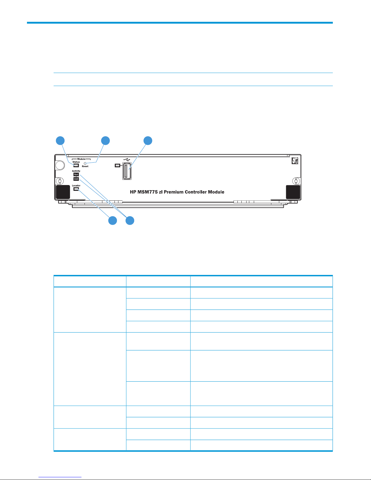
Front panel and LEDs
Figure 1 Controller front panel
1 2 3
45
5. Module Locator LED3. USB port (not used)1. Module Status LED
4. SSD Activity and Network Activity LEDs2. Module Reset button
Front panel LEDs indicate the following:
MeaningStateLED
The controller is ready.On greenModule Status
(green/orange)
The controller is starting or has booted into the service OS.Flashing green
An error has occurred.Flashing orange
The controller is powered off.Off
The services <slot-id> locator on command was
issued to assist in finding the controller.
OnModule Locator (blue)
The services <slot-id> locator blink command
was issued to assist in finding the controller.
nl
Flashing
Note: The flashing duration defaults to 30 minutes, but can
be set anywhere from 1 minute to 1440 minutes.
Default state. Otherwise, the services <slot-id>
locator off command was issued or a previous blink
request has timed out.
Off
The SSD is active.FlashingSSD Activity (green)
The SSD is not active.Off
There is network activity on one or both internal ports.FlashingNetwork Activity (green)
There is no network activity on either internal port.Off
4 Preparing for installation
Page 5
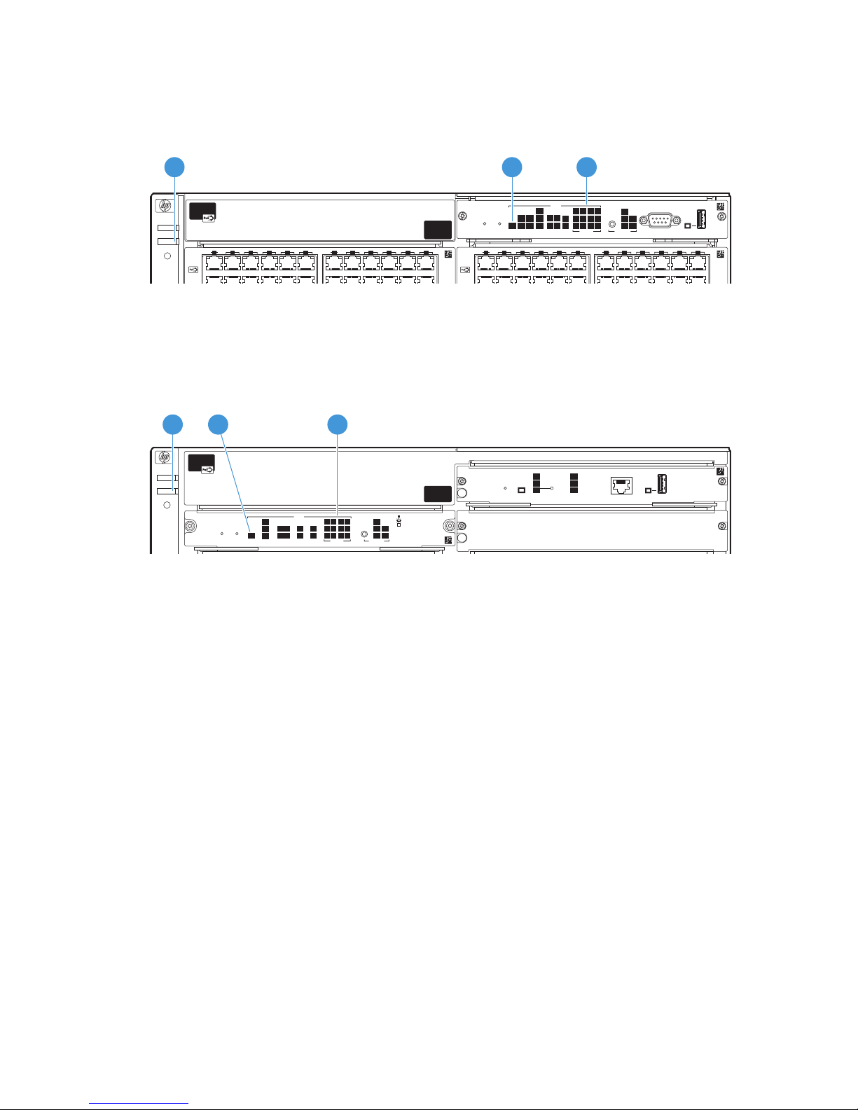
Switch LEDs
The following figures show the location of the Fault, Test, and Module Status LEDs on the switches
in which the controller can be installed.
Figure 2 Fault, Test, and Module Status LEDs on a Series 54xx zl switch
13 15 17 19 21123
3 5 7 9 11
13 15 17 19 21 23
1 3 5
PoE
Status
Modules LED Mode
Console
Auxiliary Port
Internal
Power
PoE
Pwr
TempFlashMgmt
Fan
LK
JI
H
Act
FOx
Spd
PoE
Usr
G
FEDC2
1
132
4
BA
DIMMChasTest
7 9 11
Reset
ProCurve Switch 5400zl
Management Module
J8726A
B
Clear
Link ModeLink Mode
Power
Fault
Locator
A
Link Mode Link Mode
2 3
1
1. Fault LED
2. Test LED
3. Module Status LEDs
Figure 3 Fault, Test, and Module Status LEDs on a Series 82xx zl switch
PoE
Status
Interface
Modules
LED Mode
Spd mode: off = 10 Mbps
flash = 100 Mbps
on = 1000+ Mbps
Auxiliary PortConsole
Internal
Power
EPS
Tmp
Fan
LK
JI
H
Act
FOx
Spd
PoE
Usr
G
FE
DC
2
1
Fabric
Modules
2
1
132
4
BA
Test
Reset
System
ProCurve Switch 6200zl
System Support Module (55M)
J5754A
Clear
Power
Fault
Locator
Actv
Stby
Dwn
Reset Shutdown
Status
MM
MM
1
MMMM
MM State
CF
DIM
SSM
Component Status
ProCurve Switch 8200zl
Management Module (MM)
J8781A
MM
2
2 31
1. Fault LED
2. Test LED
3. Module Status LEDs
Serial number
The serial number is required when contacting HP or a reseller for warranty assistance or for
coverage under a service agreement. Record the serial and product number for future reference.
See the warranty information for coverage details.
The serial number for the controller is located on the bottom of the controller. The serial number of
the controller can also be found in the management tool or through the CLI.
Switch LEDs 5
Page 6
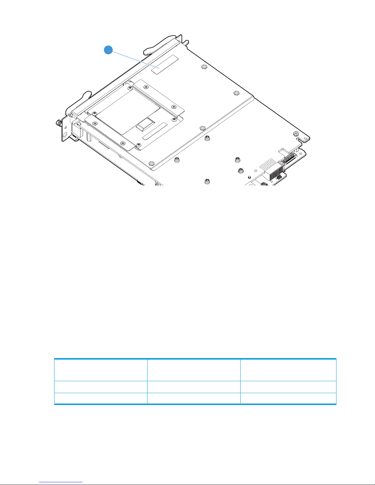
Figure 4 Locating the controller serial number
1
1. Controller serial number (SN: SGxxxxxxxx)
Installation precautions
• Static electricity can severely damage the electronic components on the controller. When
handling and installing the controller, follow these procedures to avoid damage from static
electricity:
• Handle the controller by its bulkhead or edges and avoid touching the components and
the circuitry on the board.
• When installing the controller, equalize any static charge difference between your body
and the switch by wearing a grounding wrist strap and attaching it to the metal body of
the switch, or by frequently touching the metal body of the switch.
• For safe operation, proper switch cooling, and reduction of electromagnetic emissions, ensure
that a slot cover is installed on any unused controller slot. For safety, be sure that no more
than one slot is uncovered when the switch is powered on.
• The temperature specifications of the controller must be followed.
Environmental specifications
Non-Operating
-40°C to 70°C (-40°F to 158°F)
Operating
0°C to 45°C (32°F to 113°F)
Temperature
15% to 90% at 65°C (149°F)
2
15% to 95% at 40°C (104°F)
1
Relative humidity (non-condensing)
4.6 km (15,000 ft)3.0 km (10,000 ft)Maximum altitude
1
The SSD has a maximum operational wet bulb temperature of 35°C (95°F).
2
The SSD has a maximum non-operational wet bulb temperature of 40°C (104°F).
Other documentation
For information on configuring and managing the controller, see the MSM Controllers Configuration
Guide.
6 Preparing for installation
Page 7
2 Installing
WARNING! This is a general procedure. It is the installer’s responsibility to perform the installation
in accordance with local electrical code and regulations.
A maximum of six controllers can be installed in a 5406 zl, 8206 zl, 5412 zl, and 8212 zl chassis.
The above information assumes that no other service modules are installed in the chassis. See
“Environmental specifications” (page 6) for additional restrictions.
NOTE: If you insert a replacement controller into a slot that previously contained a module of a
different type, you must perform a switch reset. A module of a different type is any module other
than the MSM775 zl Controller (J9840A), Advanced Services v2 zl Module with HDD (J9857A),
or Advanced Services v2 zl Module with SSD (J9858A).
Installation procedure
1. Use a Torx T-10 or flat-bladed screwdriver to loosen the screws in the cover plate over the slot
where the controller is to be installed. Remove the cover plate and store it for possible future
use.
2. Hold the controller by its bulkhead, taking care not to touch the connectors or components on
the boards.
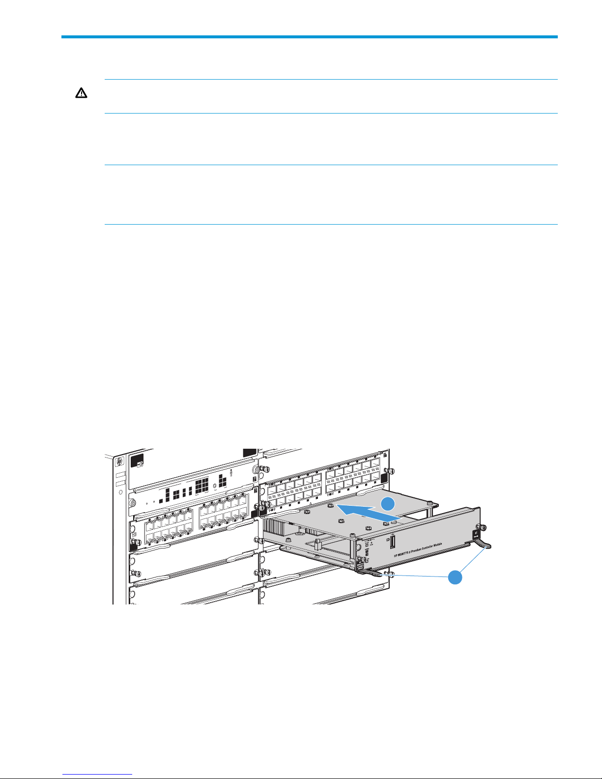
3. Open the extractor handles (1 in Figure 5 (page 7)).
4. Align the lower PC board with the card guide in the chassis, insert the controller and slide it
into the slot until it is fully inserted (2 in Figure 5 (page 7)).
nl
Note: the switch has low force, high-performance connectors. Avoid using excessive force
when installing the controller.
5. When the contacts are engaged, use the extractor handles to seat the controller completely.
6. Tighten the screws on the front panel of the controller.
Figure 5 Controller being installed
1
Link
Link
Mode
Mode
3
5
7
9
11
13
15
17
19
21
23
14
16
18
20
22
24
2
4
6
8
10
12
Link
Link
Mode
Mode
Use ProCurve mini-GBICs and SFPs only
PoE
Status
Interface
Modules
LED Mode
Spd mode: off = 10 Mbps
flash = 100 Mbps
on = 1000+ Mbps
Internal
Power
EPS
Tmp
Fan
L
K
J
I
H
Act
FOx
Spd
PoE
Usr
G
F
E
D
C
2
1
Fabric
Modules
2
1
1
3
2
4
B
A
Test
Reset
System
ProCurve Switch 6200zl
System Support Module (55M)
J5754A
Clear
Power
Fault
Locator
MM
2
1
E
C
Link
ModeLink
Mode
Link
Mode
Link Mode
1
2
1. Extractor handles
2. Controller being inserted
Verifying the controller is installed correctly
When the controller is installed correctly, it undergoes a self-test that takes 30 to 45 seconds. This
happens both when the switch is powered on after installing the controller and when the controller
is installed while the switch already has power. The switch and controller LEDs indicate if the
controller has passed the self-test, as described in the following table.
Installation procedure 7
Page 8

NOTE: At power-on and during module self-tests, all LEDs will turn on for at least 7 seconds and
go through their range of colors. After the self-tests complete, all LEDs will return to behaving
normally.
Display for a properly installed controllerLocation of LEDLED
Off.
Note: If the controller was installed with the switch powered off,
and then the switch was powered on, the Test LED stays on for
the duration of the switch self-test.
SwitchTest
Figure 2 (page 5) and Figure 3 (page 5) show the location of
the Fault, Test, and Status LEDs on a 54xx zl or 82xx zl series
switch, respectively.
Off.SwitchFault
On.SwitchModule Status
On green.
“Controller front panel” (page 4) shows the location of all
controller LEDs.
ControllerModule Status
Flashing green.ControllerSSD Activity
Error conditions
Error conditions indicated by the controller LEDs are described in “Front panel and LEDs” (page 4).
NOTE: Allow sufficient time for the controllers to start up. If the chassis has already booted and
you are booting only one controller, it can take up to one minute. Booting multiple controllers at
one time can take longer (several minutes).
8 Installing
Page 9

3 Initially connecting and configuring
This chapter describes how to connect to the switch, configure the switch for the controller, and
then perform initial controller configuration. Finally, information on restarting and resetting the
controller is provided.
Connect to the switch
Although full information on the switch command line interface (CLI) is provided in the switch
documentation, the basic switch CLI commands needed to work with the controller are provided
in this document.
NOTE: Although not described in this document, it is also possible to perform switch configuration
via a telnet or ssh session with an Ethernet connection to the switch.
1. Using a serial console cable, connect a computer to the serial port of the switch Management
Module.
2. On the computer, configure a serial terminal program in VT100 mode, with Baud rate 9600,
8 data bits, no parity, 1 stop bit, and no flow control.
3. Open a terminal session with the switch and press Enter several times until the welcome screen
appears. (A different screen will appear if another session was already open.)
Connect to the switch 9
Page 10

4. Press any key to continue. The switch CLI prompt appears. It looks similar to:
HP-5406zl#
NOTE: If the switch menu appears instead, return to the top-level menu and select Command
Line (CLI).
The switch CLI prompt appears, similar to:
HP-5406zl#
Verify switch software version
Before configuring the controller, verify that the switch software is Version K.15.13 or later.
1. At the switch CLI prompt, enter:
show version
2. The software version information is displayed:
Image stamp: ...
<date, time>
K.15.XX
If necessary, update the switch software according to the directions in your switch documentation.
Configure the switch for the controller
The switch must be configured to work properly with the controller.
This procedure assumes that there are Ethernet port modules installed in slot A, and that the controller
is installed in slot D. Sample VLAN IDs and names are used. You will need to adjust the procedure
according to slots chosen, and the VLAN IDs and names used on your switch.
About controller ports
The controller features two 10GbE ports, Internet and LAN. These ports do not have RJ-45 Ethernet
jacks. Instead, these ports connect through the switch backplane and are mapped to specific RJ-45
jacks on an Ethernet module by VLAN configurations in the switch. The switch references the Internet
and LAN ports according to the switch slot in which the controller is installed. For example, if the
controller is installed in slot D, the first port (D1i) corresponds to the Internet port, and the second
port (D2i) corresponds to the LAN port.
10 Initially connecting and configuring
Page 11

This guide, and the MSM Controllers Configuration Guide, use the terms Internet port and LAN
port to refer to the Ethernet interfaces on the controller, instead of the port names on the switch.
NOTE: The “i” suffix on the ports indicates that it is an internal port. A third internal port (D3i in
the example) is displayed, but is nonfunctional.
Define and assign VLANs
1. At the switch CLI prompt, enter:
menu
2. Press Enter.
3. Select Switch Configuration.
4. From the Switch Configuration menu, select VLAN Menu.
Configure the switch for the controller 11
Page 12

5. Select VLAN Names.
6. Add two VLANs, one for the Internet port and another for the LAN port. For example, use
VLAN ID 10 with name MSM775_Int for the Internet port and VLAN ID 15 with name
MSM775_LAN for the LAN port.
7. Select Back to return to the VLAN Menu.
12 Initially connecting and configuring
Page 13

8. Select VLAN Port Assignment.
9. Select Edit, and then use the arrow keys to select the DEFAULT_VLAN column of port D1i.
(Ports D1i and D2i respectively define the VLAN assignment for the controller Internet and
LAN ports.)
NOTE: In addition to DEFAULT_VLAN, columns are now present for the two VLAN names
(MSM775_Int and MSM775_LAN) defined in the previous steps.
10. Use the space bar to change values and the arrow keys to move between items. Moving from
left to right, set port D1i to No, Untagged, No. Set port D2i to No, No, Untagged. Ports D1i
and D2i should now look like this:
Configure the switch for the controller 13
Page 14

11. Use the arrow keys to select the DEFAULT_VLAN cell for port A1.
12. Assign MSM775_Int to port A1, and MSM775_LAN to port A2. Use the space bar to change
values and the arrow keys to move between items. Moving from left to right, set port A1 to
No, Untagged, No. Set port A2 to No, No, Untagged. Ports A1 and A2 should now look like
this:
NOTE: Consider reserving additional ports for connecting access points to the LAN port.
For example, you could set ports A3 and A4 to use the same VLAN as the LAN port,
MSM775_LAN in this example. You could then connect access points to ports A3 and A4 of
the Ethernet module.
14 Initially connecting and configuring
Page 15

13. Select Save when finished, and then select Return to Main Menu.
Configure the controller
Assign an IP address to the LAN port
To successfully connect to the controller and configure it via its web interface, you must first assign
an IP address to the controller LAN port using the switch CLI. The starting point for this procedure
is the switch CLI prompt, that (on a 5406 zl switch) looks like this:
HP-5406zl#
1. Select the controller, by specifying the slot:
services <slot-id> serial
2. If needed, press Enter twice and login using admin for Login and admin for Password.
3. Enable the controller CLI and select its config context.
enable
config
4. Select the controller LAN port interface.
interface ip lan
5. Assign an IP address of 192.168.1.1 and a subnet mask of 255.255.255.0.
ip address 192.168.1.1/24
6. Press Ctrl+Z to return to the switch CLI.
NOTE: For proper functioning of the MSM775 zl, the LAN port must not be left at its default
address of 0.0.0.0.
Perform initial controller configuration
1. On your computer, disable the wireless port and configure the Ethernet port to use the static
IP address 192.168.1.2. Set the subnet mask to 255.255.255.0, default gateway to
192.168.1.1, and DNS server to 192.168.1.1.
2. Connect network cables as follows:
a. Connect the Ethernet port on your computer to the controller LAN port.
b. Connect the controller Internet port to a network with Internet access.
Configure the controller 15
Page 16

3. Management and configuration of the controller occurs through its web interface. Open the
web interface in your web browser (Microsoft Internet Explorer 9 or later, or Mozilla Firefox
17 or later) by connecting to the address: https://192.168.1.1.
(If the IP address of the controller is in the restricted sites list of your browser, you will not be
able to access the controller web interface.)
4. A security certificate warning might appear the first time you connect to the web interface.
This is expected. Select the option in your web browser to continue.
5. On the Login page, enter admin for both Username and Password, and then select Login.
6. A workflow to set initial controller settings starts automatically. After you accept the HP Licence,
read the instructions and respond to the prompts on each page, and select Next to continue
to the next workflow page.
CAUTION: To maintain regulatory compliance, during this workflow you must select the
correct country in which the controller and any controlled APs will operate. Selecting an
incorrect country can result in illegal operation and can cause harmful interference to other
systems.
When you reach the Network Interface step, make a note of the Internet network interface IP
address. You will need this address in step 10.
7. When initial setup is complete, you are prompted to try the new Simplified UI. Select Try it
Later to stay in the Advanced UI, which is the default interface the first time you connect to
the controller.
8. Click the administrator icon in the title bar and select Logout. (The name next to the icon will
be the name you defined during the initial configuration procedure. By default, it is admin.)
9. Disconnect your computer from the controller LAN port. Connect it to the same network to
which the controller Internet port is connected. Configure the Ethernet port on your computer
with an IP address (or addressing method) that is compatible with this network.
10. Open the controller web interface in your browser by specifying the controller Internet port IP
address.
11. On the Login page, enter the new login credentials you defined for Username and Password,
and then select Login.
12. You will be prompted to try the new Simplified UI.
• Select Let’s try it out to switch to the Simplified UI. The Simplified UI provides access to
the most commonly configured controller options, and features wizards to make
configuration tasks easy. For initial configuration of the controller, HP recommends using
the Simplified UI. The first time the Simplified UI starts, it shows the product tour, which
provides a quick overview of the key features of the interface.
• Select Try it Later to stay in the Advanced UI, which provides access to advanced
configuration settings on the controller. (This is the same interface that was used in previous
software releases.)
13. You are now ready to connect a controlled AP and deploy a wireless network.
• If you are using the Simplified UI, open the online help and select the topic Working with
controlled APs under the section Tell Me About.
• If you are using the Advanced UI, see Working with controlled APs in the MSM Controllers
Configuration Guide.
16 Initially connecting and configuring
Page 17

Restarting and resetting the controller
Restarting the controller
HP recommends that you use the web interface to restart the controller as follows:
• Simplified UI
Select Views > Home > Summary > Restart.
• Advanced UI
Select Controller >> Maintenance > System > Restart.
Alternatively, the switch CLI can be used:
services <slot-id> reload
Where <slot-id> identifies the switch slot containing the controller. A confirmation message
appears. Respond with "y" to continue.
The controller can also be restarted by pressing the Reset button found on the front panel “Controller
front panel” (page 4). To reset the controller, insert a paper clip into the Reset button hole, and
press and quickly (in less than four seconds) release the button.
Resetting the controller to factory defaults
HP recommends that you use the web interface to reset the controller to factory defaults as follows:
• Simplified UI
1. Select Views > Software Settings > Backup & Restore > Restore.
2. Under Restore to Factory Defaults, select Restore to Factory Defaults.
• Advanced UI
1. Select Controller >> Maintenance > Config file management.
2. Under Reset configuration, select Reset.
Alternatively, a controller can be reset to factory defaults by pressing the Reset button found on
the front panel “Controller front panel” (page 4). To reset the controller to factory defaults, insert
a paper clip into the Reset button hole, and press and hold (for more than four seconds) the button
before releasing.
NOTE: In rare cases the controller may have been earlier configured to boot the service OS. If
the controller is configured to boot the service OS, when you reset to factory defaults the service
OS will get booted. However, the reset process will never complete, and the four LEDs will continue
to flash until you re-configure the controller to boot to the controller software on the SSD. To
re-configure the controller to boot to the controller software on the SSD, enter:
services <slot-id> boot product
Where <slot-id> identifies the switch slot containing the controller. A confirmation message
appears. Respond with "y" to continue.
When you reset the controller to factory defaults, it loses its LAN port IP address and Internet port
configuration. Once the controller reboots and the Status LED stays on, follow the directions in
“Configure the controller” (page 15).
Restarting and resetting the controller 17
Page 18

4 Support and other resources
Online documentation
You can download documentation from the HP Support website at: www.hp.com/support/manuals.
Search by product number or name.
Contacting HP
For worldwide technical support information, see the HP support website: www.hp.com/networking/
support
Before contacting HP, collect the following information:
• Product model names and numbers
• Technical support registration number (if applicable)
• Product serial numbers
• Error messages
• Operating system type and revision level
• Detailed questions
HP websites
For additional information, see the following HP websites:
• www.hp.com/networking
• www.hp.com
Typographic conventions
Table 1 Document conventions
ElementConvention
Cross-reference linksBlue text: Table 1 (page 18)
Website addressesBlue, underlined text: www.hp.com
Bold text
• Keys that are pressed
• Text typed into a GUI element, such as a box
• GUI elements that are clicked or selected, such as menu
and list items, buttons, tabs, and check boxes
WARNING! Indicates that failure to follow directions could result in bodily harm or death.
CAUTION: Indicates that failure to follow directions could result in damage to equipment or data.
NOTE: Provides additional information.
18 Support and other resources
Page 19

A Regulatory information
This product is a Class A device, pursuant to Part 15 of the FCC Rules.
For important safety, environmental, and regulatory information, see Safety and Compliance
Information for Server, Storage, Power, Networking, and Rack Products, available at www.hp.com/
support/Safety-Compliance-EnterpriseProducts.
Turkey RoHS material content declaration
Türkiye Cumhuriyeti: EEE Yönetmeliğine Uygundur
Ukraine RoHS material content declaration
Обладнання відповідає вимогам Технічного регламенту щодо обмеження використання деяких
небезпечних речовин в електричному та електронному обладнанні, затвердженого постановою
Кабінету Міністрів України від 3 грудня 2008 № 1057
Turkey RoHS material content declaration 19
Page 20

B Replacing hardware components
Replacing or removing a controller
HP recommends that the controller be shut down before removing or replacing it. The preferred
method of shutting down the controller is through the CLI:
services <slot-id> shutdown
Where <slot-id> identifies the switch slot containing the controller. A confirmation message
appears. Respond with "y" to continue.
It is possible to "hot-swap" one module for another of the same type. That is, replace one module
with another while the switch is still powered on without interrupting the operation of the rest of
the switch ports. If the modules are not the same type, the switch must be rebooted.
CAUTION: It is mandatory for you to wait at least five seconds between removing a controller
and re-installing it or replacing it with another.
To replace one controller with another, or to remove a controller without replacing it, use the
following procedure:
1. Using a Torx T-10 or flat-bladed screwdriver, loosen the retaining screws securing the controller
(1 in Figure 6 (page 21)).
2. Open the extractor handles (2 in Figure 6 (page 21)) and pull the controller out from the slot.
3. Do one of the following:
• If installing another module of the same type, go to “Installation procedure” (page 7)
and begin with step 2. A switch reset is not required. The current configuration in that
slot will apply to the new controller.
• If another controller will not be installed in the slot (the slot will be left empty), re-install
the cover plate over the slot opening using the retaining screws.
CAUTION: For proper cooling and reduction of electromagnetic emissions, ensure that a slot
cover is installed on all unused slots.
Replacing the SSD
HP recommends that the controller be shut down before removing or replacing the SSD. The
preferred method of shutting down the controller is through the CLI:
services <slot-id> shutdown
Where <slot-id> identifies the switch slot containing the controller. A confirmation message
appears. Respond with "y" to continue.
It is possible to remove the controller while the switch is powered on.
The following procedure describes replacing the SSD in the controller. Refer to Figure 6 (page 21).
1. Using either a Torx T-10 or flat-bladed screwdriver, loosen the retaining screws securing the
controller (1 in Figure 6 (page 21)).
2. Open the extractor handles (2 in Figure 6 (page 21)) and pull the controller out from the slot
and turn it over.
3. Using a Torx T-10, remove the four SSD retaining screws (3 in Figure 6 (page 21)).
4. Slide the SSD towards the faceplate of the controller to disconnect the connectors.
5. Using the pull tab (4 in Figure 6 (page 21)), lift the SSD out from the controller.
6. Install the new SSD into the controller by placing the non-connector side in first, then sliding
the connector side back (away from the faceplate) to engage the connectors.
7. Re-install the four SSD retaining screws using a Torx T-10 screwdriver.
8. Re-install the controller into the switch. Refer to “Installation procedure” (page 7) and begin
with step 2.
20 Replacing hardware components
Page 21

Figure 6 Replacing the controller SSD
PoE
Status
Interface
Modules
LED Mode
Spd mode: off = 10 Mbps
flash = 100 Mbps
on = 1000+ Mbps
Internal
Power
EPS
Tmp
Fan
L
K
J
I
H
Act
FOx
Spd
PoE
Usr
G
F
E
D
C
2
1
Fabric
Modules
2
1
1
3
2
4
B
A
Test
Reset
System
ProCurve Switch 6200zl
System Support Module (55M)
J5754A
Clear
Power
Fault
Locator
MM
2
MM
1
C
1
Link
Link
Mode
Mode
3
2
4
1
PoE
Status
Interface
Modules
LED Mode
Spd mode: off = 10 Mbps
flash = 100 Mbps
on = 1000+ Mbps
Internal
Power
EPS
Tmp
Fan
L
K
J
I
H
Act
FOx
Spd
PoE
Usr
G
F
E
D
C
2
1
Fabric
Modules
2
1
1
3
2
4
B
A
Test
Reset
System
ProCurve Switch 6200zl
System Support Module (55M)
J5754A
Clear
Power
Fault
Locator
MM
2
Reset
Status
MM
1
2
3
4
H
Link ModeMode
E
C
1
Link
Link
Mode
Mode
3
5
7
9
11
13
15 17 19
21
14
16
18
20
22
2
4
6
8
10
12
Link
Link
Mode
Mode
Use ProCurve mini-GBICs and SFPs only
2
4
3
3. SSD retaining screws1. Controller retaining screws
4. SSD pull tab2. Extractor handles
Replacing the SSD 21
 Loading...