

Page 1

HP MSM760 Controllers Installation Guide
Abstract
This document describes how to install and initially configure MSM760 Controllers. This information applies to the MSM760
Access Controller (J9421A) and the MSM760 Premium Mobility Controller (J9420A). These products are hereafter referred to
as controller.
HP Part Number: 5998-6889
Published: November 2014
Edition: 1
Page 2

© Copyright 2013, 2014 Hewlett-Packard Development Company, L.P.
The information contained herein is subject to change without notice. The only warranties for HP products and services are set forth in the express
warranty statements accompanying such products and services. Nothing herein should be construed as constituting an additional warranty. HP shall
not be liable for technical or editorial errors or omissions contained herein.
Acknowledgments
Microsoft® and Windows® are U.S. registered trademarks of Microsoft Corporation.
Warranty
WARRANTY STATEMENT: To obtain a copy of the warranty for this product, see the warranty information website:
http://www.hp.com/support/Networking-Warranties
Page 3

Contents
1 Preparing for installation.............................................................................4
Package contents......................................................................................................................4
Identifying controller components................................................................................................4
Installation precautions..............................................................................................................7
2 Installing the controller................................................................................8
Prepare the installation site .......................................................................................................8
Installing the controller..............................................................................................................8
3 Configuring the controller..........................................................................11
Performing the initial configuration............................................................................................11
Verifying guest access (optional)...............................................................................................12
Restarting the controller...........................................................................................................16
Resetting to factory defaults......................................................................................................16
4 Working with controlled APs......................................................................18
Verifying AP discovery............................................................................................................18
Testing the wireless public access network..................................................................................18
5 Support and other resources......................................................................19
Online documentation.............................................................................................................19
Contacting HP........................................................................................................................19
HP websites...........................................................................................................................19
Typographic conventions.........................................................................................................19
A Specifications..........................................................................................20
Supported power cables..........................................................................................................20
B Regulatory information..............................................................................22
Contents 3
Page 4
1 Preparing for installation
1 2
3 4 5 6 7
Package contents
The controllers are shipped with the following components:
• Console cable, DB-9 to RJ-45 (5188-6699)
• Accessory kit (5069-5705) which includes:
Two mounting brackets◦
◦ Eight 8mm machine screws for attaching the mounting brackets to the controller
◦ Four 5/8-inch number 12-24 screws for attaching the controller to a rack
◦ Four rubber feet for horizontal mounting on a flat surface
• Documentation
• Power cable, see “Supported power cables” (page 20)
Identifying controller components
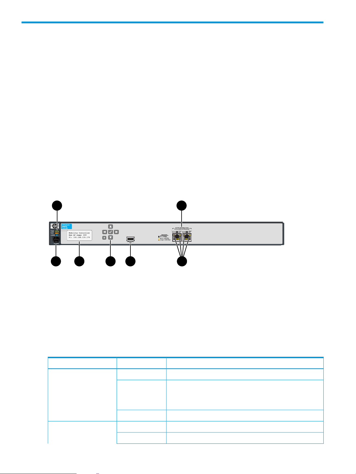
Figure 1 Front view of the controller
4. LCD display
LEDs
The following table indicates the function of the status LEDs. See Figure 1 (page 4) for the location
of the status LEDs.
Flashing
5. Keypad (not used)1. Power, Fault, and Locator LEDs
6. USB port (not used)2. Ethernet Ports: 1=Internet, 2=LAN
7. Ethernet LEDs3. Console port
DescriptionStateLED
The controller has no power.OffPower (green)
The controller is starting up. A power LED that continues to flash
after several minutes indicates that the firmware failed to load.
Reset or power cycle the controller. If this condition persists, contact
customer support.
The controller is fully operational.On
There are no fault conditions on the controller.OffFault (orange)
A fault has occurred on the controller.Flashing
4 Preparing for installation
Page 5

DescriptionStateLED
Troubleshooting problems
The following table shows LED patterns that indicate problem conditions.
On
OnLocator (blue)
On
On briefly at the beginning of the self-test after the controller is
powered on or reset. If it remains on, the controller has encountered
a fatal hardware failure, or has failed its self-test. For more
information, see “Troubleshooting problems” (page 5).
The Locator LED is used to locate a specific controller in a group
of equipment, typically a rack.
The standard state.Off
No Ethernet link has been established.OffEthernet LEDs (right edge)
Transmit/receive activity is occurring.Flashing
An Ethernet link has been established, but there is no
transmit/receive activity.
Link speed 10 MbpsOffEthernet LEDs (left edge)
Link speed 100 MbpsOn (green)
Link speed 1000 Mbps (gigabit)On (orange)
What to doProblemLED indication
The power LED is
off, even though the
power cable
plugged in.
remains on.
The controller is not plugged into
an active AC power source.
A hardware failure has occurred.The fault LED
1. Verify that the power cable is firmly attached to the
controller and plugged into an active power source.
2. Power cycle the controller by unplugging and plugging
the power cable back in.
3. If the power LED remains off, verify the AC power source
by:
• Plugging another device into the outlet
• Plugging the controller power cable into a different
outlet
• Using a different (approved) power cable
4. If the power source and power cable are good and this
condition persists, the power supply might have failed.
Call your HP authorized LAN dealer, or use the electronic
support services from HP to get assistance. For more
information, see the warranty information website:
http://www.hp.com/support/Networking-Warranties
1. Power cycle the controller by unplugging and plugging
the power cable back in.
2. If this condition persists, the controller might have failed.
Call your HP authorized LAN dealer, or HP customer
support. For more information, see the warranty
information website:
http://www.hp.com/support/Networking-Warranties
Console port
The controller console port is a standard serial port with an RJ-45 connector. To connect to a
computer, use the supplied DB-9 to RJ-45 console cable.
Identifying controller components 5
Page 6

LCD display
The LCD displays the following:
• The controller type, either Mobility Controller or Access Controller
• The maximum number of supported APs, according to the controller license
• The IP address of the Internet port.
During start up, the LCD displays a system booting message.
Until the controller receives its IP address from a DHCP server, the address displays as: 0.0.0.0
Keypad
The keypad is not used in this release.
USB port
The USB port is not used in this release.
MAC address
The Internet port MAC address is printed on the front of the controller. The LAN port MAC address
is the Internet port MAC address plus 1.
Ethernet ports
The controller has two auto-sensing 10/100/1000 Ethernet ports with RJ-45 connectors. Connector
1 (on the left) is used for the Internet port and connector 2 (on the right) is used for the LAN port.
Ethernet status LEDs on the left and right edges of the RJ-45 connectors indicate speed and activity.
6 Preparing for installation
Page 7

Installation precautions
Observe the following precautions when installing the controller.
WARNING!
• The rack or cabinet must be adequately secured to prevent it from becoming unstable and
falling over.
Install products as low as possible in a rack or cabinet, with the heaviest devices at the bottom
and progressively lighter devices installed above.
• For safe operation, only install the controller horizontally, with the bottom side down.
CAUTION:
• Ensure that the power source circuits are properly grounded, and use the power cable supplied
with the controller to connect it to the power source.
• If your installation requires a different power cable than the one supplied with the controller,
be sure to use a power cable displaying the mark of the safety agency that defines the
regulations for power cables in your country. The mark is your assurance that the power cable
can be used safely with the controller.
• Connect the controller to an AC outlet that is easily accessible in case the controller must be
powered off.
• Ensure the controller does not overload the power circuits, wiring, and over-current protection.
To determine the possibility of overloading the supply circuits, add together the ampere ratings
of all devices installed on the same circuit as the controller and compare the total with the
rating limit for the circuit. The maximum ampere ratings are typically printed on the devices
near the AC power connectors.
• Do not install the controller in an environment where the operating ambient temperature might
exceed 40°C (104°F).
• Ensure the air flow around the sides and back of the controller is not restricted.
Installation precautions 7
Page 8

2 Installing the controller
The controller comes with an accessory kit that includes the brackets for mounting it in a standard
19-inch telco rack or in an equipment cabinet, and with rubber feet that can be attached so the
controller can be securely located on a horizontal surface. Although the brackets are designed to
allow it to be mounted in a variety of locations and orientations, you must install the controller
horizontally.
Prepare the installation site
• Installation location: Before installing the controller, plan its location relative to other devices
and equipment and consider the following:
• The front of the controller requires at least 7.6 cm (3 inches) of space for the twisted-pair
cabling.
• The back of the controller requires at least 3.8 cm (1 1/2 inches) of space for the power
cable.
• The sides of the controller, must have at least 7.6 cm (3 inches) of space for cooling,
except if the controller is installed in an open EIA/TIA rack.
• Cabling Infrastructure: Ensure the cabling infrastructure meets the necessary network
specifications. The following table describes cable types and lengths.
For 10 Mbps, 100 Mbps, or 1000 Mbps operation:
Use Cat 5 or better, 100-ohm unshielded twisted-pair
(UTP) or shielded twisted-pair (STP) balanced cable. For
Cat 5e cabling or better. twisted-pair cables for connecting to network devices
Installing the controller
After determining the configuration and preparing the site, install the controller in a stable location.
The controller can be installed in a rack or cabinet, or mounted on a table or shelf.
WARNING! For safe operation, read the precautions in “Installation precautions” (page 7),
before you install the controller.
Installing the controller in a rack or cabinet
The controller is designed to be installed in any EIA-standard 19-inch telco rack or communication
equipment cabinet.
Length limitsCable type
100 meters
Note: The controller is compatible with the IEEE 802.3ab
standard including the Auto MDI/MDI-X feature, which
allows use of either straight-through or crossover1000 Mbps (gigabit) operation, HP recommends using
including end nodes, such as computers; or to other
switches, hubs, and routers.
Note: For 1000 Mbps operation, all four wire pairs are
used for data transmission.
8 Installing the controller
Page 9

NOTE: Equipment Cabinet Note
The 12-24 screws supplied with the controller are the correct threading for standard EIA/TIA open
19-inch racks. If you are installing the controller in an equipment cabinet such as a server cabinet,
use the clips and screws that came with the cabinet instead of the 12-24 screws that are supplied
with the controller.
Before performing the following procedure, determine which four holes you will be using in the
cabinet and install all four clips.
1. Use a #1 Phillips (cross-head) screwdriver to attach the mounting brackets to the controller
with the included 8-mm M4 screws.
Figure 2 Controller with mounting brackets
2. Hold the controller with attached brackets up to the rack and move it vertically until the rack
holes line up with the bracket holes, then insert and tighten the four number 12-24 screws to
secure the brackets to the rack.
Figure 3 Controller rack-mount example
Installing the controller 9
Page 10

Installing the controller on a horizontal surface
Attach the supplied rubber feet to the four corners on the bottom of the controller within the embossed
angled lines. Place the controller on a table or other sturdy horizontal surface in an uncluttered
area. You might want to secure the networking cables and the power cable to a table leg or other
part of the surface structure to help prevent tripping over the cables.
CAUTION: Make sure the air flow is not restricted around the sides and back of the controller.
10 Installing the controller
Page 11

3 Configuring the controller
1
This is an initial configuration procedure for the controller, enabling you to establish a connection
through the controller to the Internet.
The controller is managed via its web-based management tool using Microsoft Internet Explorer 8
or later, or Mozilla Firefox 17 or later.
Performing the initial configuration
NOTE: HP recommends that you use the provided power supply to power the controller. Therefore,
it is the assumed powering method in all procedures in this guide.
Do not connect power or network cables to the controller until directed to do so in this procedure.
If cables are connected, temporarily disconnect them.
This procedure assumes that the controller has the default IP address of 192.168.1.1 assigned to
its LAN port. Substitute your own if different.
To initially configure the controller:
1. Configure your computer to use a static IP address in the range 192.168.1.2 to 192.168.1.254
and set the subnet mask to 255.255.255.0. Set the default gateway to 192.168.1.1 and DNS
server to 192.168.1.1.
2. Connect network cables as follows:
a. Disconnect any cable from the LAN port on your computer, and disable any wireless
connection.
b. Connect the controller LAN port (2) to the LAN port on your computer.
c. Connect the controller Internet port (1) to a network with Internet access or to the PC port
of a DSL modem or equivalent.
Figure 4 Ethernet Ports: 1=Internet, 2=LAN
3. Attach the power cable to the controller and plug it into an outlet to power on the controller.
Wait approximately 90 seconds until the power LED stops flashing.
Figure 5 Controller, rear view with power connector
1. Power connector
Performing the initial configuration 11
Page 12

4. Perform initial login tasks:
a. Using Microsoft Internet Explorer 8 or later, or Mozilla Firefox 17 or later, open page
https://192.168.1.1.
b. A security certificate warning might appear the first time you connect to the management
tool. This is expected. Select whatever option is needed in your web browser to continue
to the management tool.
c. On the Login page, enter admin for both Username and Password, and then select Login.
A workflow to set initial controller settings starts automatically.
CAUTION: To maintain regulatory compliance, during this workflow you must select
the correct country in which the controller and any controlled APs will operate. Selecting
an incorrect country can result in illegal operation and can cause harmful interference to
other systems.
d. After you accept the HP Licence, read the instructions and respond to the prompts on
each page, and select Next to continue to the next workflow page.
e. When the initial setup completes, select Go to Home Page or you can start one of these
other workflows:
CAUTION: When using teaming, you must not use the Create Guest VSC workflow.
Instead, you must manually configure guest access as described in the “Guest access and
teaming” section of the HP MSM Controllers Configuration Guide.
• Create Employees VSC: This workflow helps you create a new wireless network to
provide wireless access for employees. It lets you define how employee traffic will
be distributed onto your wired infrastructure and configure wireless security settings
to safeguard network traffic.
• Create Guest VSC: This workflow helps you create a new wireless network to provide
wireless access for guests. It lets you define how guests will be authenticated (using
a RADIUS server or the local user accounts feature on the controller) and how guests
will receive an IP address.
Verifying guest access (optional)
Although optional, HP recommends that you perform a simple verification of the guest access
interface using a local guest account. This verification uses the Create a wireless network for guests
workflow. Sample values are used; however, you can substitute your own values.
Configuring basic guest access
1. Select Automated workflows on the left side of the main menu bar.
2. To configure basic guest access, select Create a wireless network for guests and select Start
to launch this workflow.
12 Configuring the controller
Page 13

3. On the Create a new wireless network for guests page, enter Guest in theWireless network
name (SSID) box, and then select Next.
Verifying guest access (optional) 13
Page 14

4. On the Configure guest authentication page, select Use the user account feature on the
controller, and set both Username and Password to guest01. Leave all other options at their
defaults, and then select Next.
5. On the Guest DHCP addressing page, select DHCP server.
a. Define the DHCP server IP address range:
• Set Start address to 192.168.5.1
• Set End address to 192.168.5.254
• Set Netmask to 255.255.255.0
NOTE: The first address in the range is reserved for the controller gateway and DNS
(192.168.5.1 in this example). The DHCP server assigns addresses to clients at Start
address +1, (192.168.5.2 in this example).
b. Select Next.
14 Configuring the controller
Page 15

6. On the Apply guest access settings to your APs page, select Next to accept the defaults.
7. The last page in the workflow lists all configuration settings that will be applied.
Verify the settings, and then select Apply.
8. After applying your changes, a confirmation page appears showing the menu paths to each
configuration page associated with the Create a wireless network for guests workflow. For
example:
9. Select Done.
Verifying guest access (optional) 15
Page 16

Verifying guest access
This test uses your existing wired connection to the controller LAN port to test the public access
interface that is used for guest access. The controller Internet port must be connected to the Internet
for this test to be successful.
1. Open your web browser and enter the address of an Internet site, for example www.hp.com.
The controller intercepts the URL and displays the public access interface Login page.
2. Enter the Username and Password for the test account you created earlier, and then select
Proceed.
Both the interface session page (shown on left) and the public access welcome page (shown
on right) open.
3. Select Continue browsing to launch a web page.
For additional configuration and operating information, see the MSM Controllers Configuration
Guide.
Restarting the controller
The controller can be restarted by disconnecting and reconnecting the power cable.
Resetting to factory defaults
HP recommends that you use the management tool to reset the controller to factory defaults as
follows:
1. Select Controller >> Maintenance > Config file management.
2. Under Reset configuration, select Reset.
When it is impossible to use the management tool due to the loss of the manager username or
password, use the Console port to reset the controller to its factory defaults as follows:
16 Configuring the controller
Page 17

1. Power off the controller.
2. Connect the provided serial cable between the controller Console port and a PC that runs
VT-100 terminal-emulation software. See Figure 1 (page 4) for the location of the console
port.
Some software possibilities include Microsoft Hyperterminal for Windows and Minicom for
Linux (http://alioth.debian.org/projects/minicom).
3. Configure the VT-100 terminal-emulation software as follows:
• VT-100 (ANSI) terminal
• Baud rate of 9600
• 8 data bits, 1 stop bit, no parity, and no flow control
• Disable the Use Function, Arrow, and Ctrl Keys for Windows option.
• For the Hilgrave HyperTerminal program, select the Terminal keys option for the Function,
arrow, and ctrl keys act as parameter.
4. Open an appropriately-configured terminal session.
5. Power on the controller.
A system boot message appears.
6. Do not press any keyboard keys. Wait for the following LILO prompt to appear:
LILO 22.1 boot:
IMPORTANT: As soon as the LILO prompt appears, press the keyboard space bar to prevent
the automatic (non-factory-default) boot from continuing. You must tap the space bar or other
key within four seconds of the prompt appearing.
7. At the LILO prompt, enter the command linux factory and press Enter. The controller
restarts with factory defaults settings.
Resetting to factory defaults 17
Page 18

4 Working with controlled APs
When installing the controller with one or more APs operating in controlled mode, the controller
provides centralized management and control of the APs. The APs factory-default mode setting is
controlled mode. In this mode, APs are automatically configured by the controller.
Verifying AP discovery
NOTE: This procedure assumes that the controller and the AP are on the same subnet (L2
connected). For full discovery information, including configuring discovery when the controller and
the AP are separated by a router (L3 connected), see “Discovery of controlled APs” in the HP MSM
Controllers Configuration Guide.
By default, APs are configured to obtain an IP address via DHCP. Therefore, to support plug-and-play
installation, the controller should be configured to operate as a DHCP server as described in
“Configuring basic guest access” (page 12). To verify that the APs have been discovered, do the
following on the controller:
1. In the Network Tree, select the + symbol next to Controller, and then select the + symbol next
to Controlled APs.
2. In the Network Tree, select Default Group. Information about discovered APs is displayed.
Testing the wireless public access network
Test the APs using a Wi-Fi-equipped computer:
1. To ensure that you use a wireless connection, disconnect any network cable from the test
computer.
2. Configure your computer to connect to the default wireless network, HP.
3. Attempt to browse a site on the Internet. Log in to the public access interface as described in
“Verifying guest access” (page 16) and confirm that you can browse the Internet.
CAUTION: Wireless Security: HP recommends that when the controller is installed, you review
the security information in the MSM Controllers Configuration Guide, and adjust the security setting
to further safeguard the wireless network from intruders.
For additional information, see Working with controlled APs in the MSM Controllers Configuration
Guide.
18 Working with controlled APs
Page 19

5 Support and other resources
Online documentation
You can download documentation from the HP Support Center website at: www.hp.com/support/
manuals. Search by product number or name.
The following documents provide related information:
• MSM Controllers Configuration Guide
• MSM7xx Controllers Release Notes
Contacting HP
For worldwide technical support information, see the HP Networking website: www.hp.com/
networking/support
Before contacting HP, collect the following information:
• Product model names and numbers
• Technical support registration number (if applicable)
• Product serial numbers
• Error messages
• Operating system type and revision level
• Detailed questions
HP websites
For additional information, see the following HP websites:
• www.hp.com/networking
• www.hp.com
Typographic conventions
Table 1 Document conventions
Bold text
WARNING! Indicates that failure to follow directions could result in bodily harm or death.
ElementConvention
Cross-reference linksBlue text: Table 1 (page 19)
Website addressesBlue, underlined text: www.hp.com
• Keys that are pressed
• Text typed into a GUI element, such as a box
• GUI elements that are clicked or selected, such as menu
and list items, buttons, tabs, and check boxes
CAUTION: Indicates that failure to follow directions could result in damage to equipment or data.
IMPORTANT: Provides clarifying information or specific instructions.
NOTE: Provides additional information.
Online documentation 19
Page 20

A Specifications
Supported power cables
Use only these HP power cables:
Zealand
8120-4753Japan
Japan power cable warning
8121-0908Switzerland8121-0838Australia/New
8120-8929South Africa8121-0910China
8121-0974Taiwan8120-8861Continental Europe
8121-0673Thailand8120-8930Denmark
8121-0909United Kingdom/Hong Kong8121-0780India
8121-0921United States/Canada/Mexico8121-1035Israel
Physical specifications
44.3 cm (17.42 in)Width:
39 cm (15.4 in)Depth:
4.2 cm (1.64 in)Height:
6.1 kg (13.45 lbs)Weight:
Electrical specifications
The controller automatically adjusts to any voltage between 100–127 and 200–240 volts at either
50 or 60 Hz.
100–127/200–240 voltsAC voltage:
2 A/1 AMaximum current:
50/60 HzFrequency range:
Environmental specifications
Non-OperatingOperating
-40°C to 65°C (-40°F to 149°F)5°C to 40°C (41°F to 122°F)Temperature:
20% to 90% at 65°C (149°F)15% to 80% at 40°C (104°F)Relative humidity: (non-condensing)
4.6 km (15,000 ft)2 km (6,500 ft)Maximum altitude:
Acoustic specifications
Noise Emission LwA=52 dB at virtual work space according to DIN 45635 T.19.
20 Specifications
Page 21

Connectors
The 10/100/1000 Mbps RJ-45 twisted-pair ports are compatible with the following standards:
• IEEE 802.3ab 1000Base-T
• IEEE 802.3u 100Base-TX
• IEEE 802.3 10Base-T
Safety
Complies with:
• EN60950-1/IEC 60950-1
• CSA 22.2 No. 60950-1
• UL 60950-1
Battery information
CAUTION: There is a risk of explosion if battery is replaced by an incorrect type. Dispose of
used batteries according to the instructions.
Supported power cables 21
Page 22

B Regulatory information
For important information, see the Safety, Compliance, and Warranty Information document that
shipped with your controller. Also see Safety and Compliance Information for Server, Storage,
Power, Networking, and Rack Products, available at http://www.hp.com/support/
Safety-Compliance-EnterpriseProducts.
22 Regulatory information
 Loading...