

Page 1

HP Moonshot Switch
cation, setup, installation,
Part Number: 723317-002
User and Maintenance Guide
Abstract
This document is for the person who installs, administers, services, and troubleshoots switches. This guide provides identifi
and removal procedures. HP assumes you are qualified in these areas.
December 2013
Edition: 2
Page 2

© Copyright 2013 Hewlett-Packard Development Company, L.P.
The information contained herein is subject to change without notice. The only warranties for HP products and services are set forth in the express
warranty statements accompanying such products and services. Nothing herein should be construed as constituting an additional warranty. HP shall
not be liable for technical or editorial errors or omissions contained herein.
Page 3

Contents
Component and LED identification .................................................................................................. 5
Chassis front panel LEDs and buttons ........................................................................................................... 5
Moonshot-6SFP Uplink Module .................................................................................................................... 6
Uplink module components ............................................................................................................... 6
Uplink module buttons and LEDs ........................................................................................................ 6
Moonshot-4QSFP+ Uplink Module ............................................................................................................... 7
Uplink module components ............................................................................................................... 7
Uplink module buttons and LEDs ........................................................................................................ 8
Moonshot-45G Switch Module .................................................................................................................... 9
Switch module button, sensor, and LEDs ............................................................................................. 9
Moonshot-180G Switch Module ................................................................................................................ 10
Switch module button, sensor, and LEDs ........................................................................................... 10
iLO CM management port ........................................................................................................................ 11
Operations ................................................................................................................................. 12
Extend the chassis from the rack ................................................................................................................ 12
Remove the access panel.......................................................................................................................... 13
Open the cable management arm ............................................................................................................. 14
Remove the uplink module blank ............................................................................................................... 14
Remove the switch module blank ............................................................................................................... 15
Setup ......................................................................................................................................... 16
Installation information and guidelines ....................................................................................................... 16
Uplink module bays ................................................................................................................................. 17
Installing the uplink module ....................................................................................................................... 17
Installing the switch module ...................................................................................................................... 18
Configuration ............................................................................................................................. 21
Configuring the switch ............................................................................................................................. 21
Network mapping ................................................................................................................................... 22
Production network mapping ........................................................................................................... 22
Management network mapping ....................................................................................................... 23
Interfaces ............................................................................................................................................... 23
Moonshot-6SFP uplink interfaces ...................................................................................................... 23
Moonshot-4QSFP+ uplink interfaces ................................................................................................. 24
Moonshot-45G downlink interfaces .................................................................................................. 25
Moonshot-180G downlink interfaces ................................................................................................ 26
Command Line Interface ........................................................................................................................... 27
Connect to the switch console ......................................................................................................... 27
Access the CLI locally ..................................................................................................................... 27
Obtaining the switch management IP address ................................................................................... 28
Configure the Enable password ....................................................................................................... 28
Interacting with the switch from the iLO CM firmware ......................................................................... 28
Firmware ................................................................................................................................................ 30
Update the switch firmware ............................................................................................................ 30
Updating the switch firmware using the switch console ....................................................................... 30
Troubleshooting .......................................................................................................................... 32
Contents 3
Page 4

Troubleshooting resources ........................................................................................................................ 32
Illustrated parts catalog ............................................................................................................... 33
Customer self repair................................................................................................................................. 33
Parts only warranty service ....................................................................................................................... 33
Switch customer self repair components...................................................................................................... 34
Removal and replacement procedures ........................................................................................... 35
Removing the switch module ..................................................................................................................... 35
Removing the uplink module ..................................................................................................................... 35
Regulatory information ................................................................................................................ 37
Safety and regulatory compliance ............................................................................................................. 37
Turkey RoHS material content declaration ................................................................................................... 37
Ukraine RoHS material content declaration ................................................................................................. 37
Warranty information .............................................................................................................................. 37
Electrostatic discharge ................................................................................................................. 38
Preventing electrostatic discharge .............................................................................................................. 38
Grounding methods to prevent electrostatic discharge .................................................................................. 38
Specifications ......................................................................................................................................... 39
Chassis environmental specifications ................................................................................................ 39
Chassis specifications .................................................................................................................... 39
Support and other resources ........................................................................................................ 40
Before you contact HP .............................................................................................................................. 40
HP contact information ............................................................................................................................. 40
Acronyms and abbreviations ........................................................................................................ 41
Documentation feedback ............................................................................................................. 43
Index ......................................................................................................................................... 44
Contents 4
Page 5
Component and LED identification
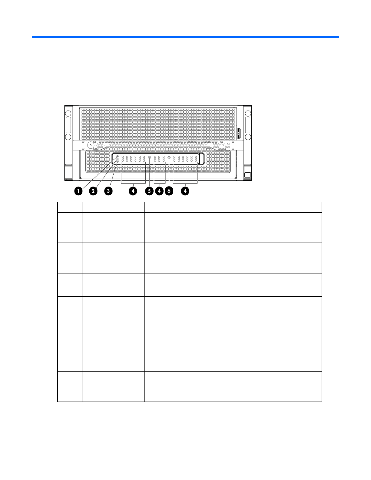
Chassis front panel LEDs and buttons
Item Description LED Status
1
2
3
4
5
6
Chassis power LED Flashing Green = The chassis is waiting to power on.
Green = Normal operation
Amber = Standby operation
Off = No power
Chassis health LED Green = Normal operation
Flashing Amber = Degraded condition
Flashing Red = Critical condition
Off = No power
Chassis UID LED/button Blue = Chassis ID is selected.
Flashing blue = System firmware update is in process.
Off = Chassis ID is not selected.
Cartridge health LEDs Green = Normal operation
Amber = Standby mode
Flashing Amber = Degraded condition
Flashing Amber (All) = Moonshot 1500 CM module is not installed.
Flashing Red = Critical condition
Off = Cartridge is not installed or no power exists.
Switch module A health
LED
Switch module B health
LED
Green = Normal operation
Flashing Amber = Degraded condition
Flashing Red = Critical condition
Off = Switch module is not installed or no power exists.
Green = Normal operation
Flashing Amber = Degraded condition
Flashing Red = Critical condition
Off = Switch module is not installed or no power exists.
Component and LED identification 5
Page 6

Moonshot-6SFP Uplink Module
Uplink module components
Item Component Description
1
2
SFP+ ports X1 through X6 support Ethernet traffic only.
SFP+ ports support the following pluggable Ethernet transceiver modules:
Serial console port For management
SFP+ ports X1–X6 1Gb or 10Gb Ethernet
• HP 1000BASE-T SFP
• HP 10GBASE-SR SFP+
• HP 10GBASE-DAC SFP+
Any available port can be used to connect to the data center. Ensure the port is populated with supported HP
transceiver modules that are compatible with the data center port type.
Uplink module buttons and LEDs
Component and LED identification 6
Page 7

Uplink module health
Green = Normal operation
Item Description Status
1
2
3
4
5
Uplink module UID
LED/button
LED
Uplink module link
LED
Uplink module
activity LED
Reset button Resets the switch module
Solid blue = Switch module ID is selected.
Flashing blue = Switch module firmware
update is in progress.
Off = Switch module ID is not selected.
Flashing amber = Degraded condition
Flashing red = Critical condition
Off = No power
Solid green = Link
Off = No link
Flashing green = Activity
Off = No activity
Moonshot-4QSFP+ Uplink Module
Uplink module components
Item Component Description
1
2
QSFP+ ports Q1 through Q4 support Ethernet traffic only.
QSFP+ ports support the following pluggable Ethernet transceiver modules:
• HP 40GBASE QSFP+
• HP 40GBASE QSFP+ SR4
• HP 40GBASE QSFP+ DAC
• HP 40GBASE QSFP+ to 4x10G SFP+
Any available port can be used to connect to the data center. Ensure the port is populated with supported HP
transceiver modules that are compatible with the data center port type.
Serial console port For management
QSFP+ ports Q1–Q4 40Gb Ethernet
Component and LED identification 7
Page 8

Uplink module buttons and LEDs
Item Description Status
1
Uplink module UID
LED/button
2
Uplink module health
LED
3
Uplink module link
LED
4
Uplink module
activity LED
5
Reset button Resets the switch module
Solid blue = Switch module ID is selected.
Flashing blue = Switch module firmware
update is in progress.
Off = Switch module ID is not selected.
Green = Normal operation
Flashing amber = Degraded condition
Flashing red = Critical condition
Off = No power
Solid green = Link
Off = No link
Flashing green = Activity
Off = No activity
Component and LED identification 8
Page 9

Moonshot-45G Switch Module
Switch module button, sensor, and LEDs
Item Description Status
1
2
3
4
5
6
*The fan speed adjusts automatically when the access panel is installed or removed.
Switch module power
LED
Switch module health
LED
Switch module uplink
activity LED
Switch module
downlink activity LED
Switch module UID
LED/button
Access panel sensor Detects the presence of the access panel*
Green = Normal operation
Amber = Standby operation
Off = No power
Green = Normal operation
Flashing amber = Degraded condition
Flashing red = Critical condition
Off = No power
Green = Link
Flashing green = Activity
Off = No activity
Green = Link
Flashing green = Activity
Off = No activity
Solid blue = Switch module ID is selected.
Flashing blue = Switch module firmware
update is in progress.
Off = Switch module ID is not selected.
Component and LED identification 9
Page 10

Moonshot-180G Switch Module
Switch module button, sensor, and LEDs
Item Description Status
1
2
3
4
5
6
*The fan speed adjusts automatically when the access panel is installed or removed.
Switch module power
LED
Switch module health
LED
Switch module uplink
activity LED
Switch module
downlink activity LED
Switch module UID
LED/button
Access panel sensor Detects the presence of the access panel*
Green = Normal operation
Amber = Standby operation
Off = No power
Green = Normal operation
Flashing amber = Degraded condition
Flashing red = Critical condition
Off = No power
Green = Link
Flashing green = Activity
Off = No activity
Green = Link
Flashing green = Activity
Off = No activity
Solid blue = Switch module ID is selected.
Flashing blue = Switch module firmware
update is in progress.
Off = Switch module ID is not selected.
Component and LED identification 10
Page 11

iLO CM management port
The iLO CM management port provides communication with the switch service port interface and is used for
remote sessions. All service port traffic is routed through the iLO/MGMT port, located on the iLO CM module:
The switch service port interface is enabled by default and can be used with the switch serial console port
when making configuration changes.
The switch serial console port is on the uplink module. To identify the switch serial console port, see uplink
module components (on page 7, on page 6).
To find the switch service port IP address for remote management, see "Obtaining the switch management IP
address (on page 28)."
Component and LED identification 11
Page 12

Operations
Extend the chassis from the rack
1. Pull down the quick release levers on each side of the chassis.
2. Extend the chassis from the rack until it locks once.
3. Press the push tab on the rail, and then fully extend the chassis.
WARNING: To reduce the risk of personal injury or equipment damage, be sure that the rack is
adequately stabilized before extending a component from the rack.
4. After performing the installation or maintenance procedure, slide the chassis back into the rack, and
then press the chassis firmly into the rack to secure it in place.
WARNING: To reduce the risk of personal injury, be careful when pressing the server rail-release
latches and sliding the server into the rack. The sliding rails could pinch your fingers.
Operations 12
Page 13

Remove the access panel
IMPORTANT: After performing a procedure inside the chassis, always install the access panel on
the chassis when complete. Do not operate the chassis for long periods of time with the access
1. Release the access panel latch.
2. Slide the access panel back about 1.5 cm (0.5 in).
3. Lift and remove the access panel.
panel removed.
Operations 13
Page 14

NOTE: Turn the access panel over to locate the hood labels. These labels provide information on
installing various options, flexible memory configurations, LED status indicators, and switch
settings.
Open the cable management arm
To open, lift the cable management arm up as you swing it open.
Remove the uplink module blank
Remove the component as indicated.
Operations 14
Page 15

Remove the switch module blank
Remove the component as indicated.
Operations 15
Page 16

Setup
Installation information and guidelines
Before installing the module, review the following:
• Always install the switch module and the uplink module in corresponding bays. Both components must
be installed for normal operation.
• The switch module and the uplink module can be installed in any order.
• The switch module and the uplink module power down when either module is removed from the chassis.
• The switch module and the uplink module power up after both modules are installed in the chassis.
• Removing any component from bay A or bay B does not disrupt traffic for the other switch.
• Always use the recommended firmware version. For current information on recommended firmware
versions, see the HP website (http://www.hp.com/go/moonshot/download).
• For the most current product information, see the HP Moonshot Information Library
(http://www.hp.com/go/moonshot/docs).
Setup 16
 Loading...