

Page 1

M8201R Fibre Channel
to SCSI Router
Installation and User’s
Guide
Abstract
This guide describ es how to install and configure the Fibr e Channe l to SCS I route r with
a Fibre Channel ServerNet adapter (FCSA) on an HP Integrity NonStop™ NS-series
server.
Product Version
N.A.
Supported Release Version Updates (RVUs)
This guide supports H06.11 and all subsequent H-series RVUs until otherwise
indicated by its replacement publication.
Part Number Published
529971 -005 July 20 07
Page 2

Document History
Part Number Product Version Published
529971- 005 N.A. July 2007
529971- 001 N.A. June 2005
Page 3

M8201R Fibre Channel
to SCSI Router
Installation and User’s G uide
Index Figures Tables
What’s New in This Manual v
Manual Information v
New and Changed Information v
About This Manual vii
Notation Conventions vii
1. Overview of the Fibre Channel to SCSI Router
Fibre Channel to SCSI Router 1-1
High Performance for Faster Backups 1-2
Supported Storage Devices 1-3
Data Connections 1-3
Power Requirements and Physical Specifications 1-3
2. Getting Started
Location 2-1
Unpacking the Box 2-1
Mounting the Fibre Channel to SCSI Router on a Desktop 2-2
Mounting the Fibre Channel to SCSI Router in a Rack 2-2
Required Tools
Installation Procedure With Ear Brackets 2-2
2-2
3. Installing the Fibre Channel to SCSI Router for the NonSt op
NS-Series Server
Installation 3-1
4. Configuring the Fibre Channel to SCSI Router for the NonStop
NS-Series Server
Configuration 4-1
5. Troubleshooting the Fibre Channel to SCSI Router
Visual Inspection 5-1
Technical Support 5-1
Hewlett-Packard Company—529971-005
i
Page 4

Contents
Indicators 5-2
6. Hardware Replacement Procedures
Tape Drive and Fibre Channel to SCSI Router Replacement 6-1
Tape Drive Replacement 6-1
Fibre Channel to SCSI Router Replacement 6-2
A. Product Specifications
Power Requirements A-2
Power A-2
Physical Specifications A-2
Operating Environment A-2
Non-operating Environment A-2
Connection Support ed A-2
B. Using the Serial Interface
6. Hardware Replacement Procedures
Serial Port Connection B-1
Autobaud Feature B-1
Setting Up Serial Port Communications B-2
Ethernet Configuration B-3
C. Configuring OSM for Monitoring the Fibre Channel to SCSI
Router
Connecting the Hardware C-1
Configuring the Fiber Channel to SCSI Router for OSM Monitoring C-2
Safety and Compliance
Index
Examples
Figures
Figure 1-1. Hardware Configuration 1-2
Figure 2-1.
Figure 2-2.
Installing Cage Nuts 2-3
Locating Front of Ear Brackets 2-4
Figure 2-3. Attaching Ear Brackets 2-5
Figure 2-4. Mounting at Front of Rack 2-6
Figure 2-5.
Figure 3-1.
Figure 3-2. Front View of the Fibre Channel to SCSI Router 3-3
M8201R Fibre Channel to SCSI Router Installation and User’s Guide—529971-005
Mounting at Back of Rack 2-7
SCSI Cable 3-2
ii
Page 5

Contents
Figure 3-3. Rear View of the Fibre Channel to SCSI Router 3-3
Figure 3-4. Front View of the Tape Drive 3-4
Figure 3-5. Rear View of the Tape Drive 3-4
Figure 3-6. View of Two FCSAs at the Rear of Server 3-6
Figure 4-1. Rear View of the Fibre Channel Router 4-2
Figure 5-1. LED Indicators 5-2
Figure 6-1. Location of the Power Switch on the Tape Drive 6-1
Figure 6-2. Rear View of the Fibre Channel to SCSI Router 6-2
Figure 6-3. Rear View of the Fibre Channel Router 6-3
Figure A-1. Fibre Channel to SCSI Router A-1
Figure A-2. Rear Panel Components A-1
Figure B-1. Fibre Channel to SCSI Router Serial Port B-1
Figure B-2. Ethernet Configuration Menu B-3
Figure C-1. OSM Tree View C-2
Figure C-2. Actions Dialog Box C-3
Tables
Tables
Table 3-1. SCSI Cable Part Numbers and Descriptions 3-1
Table 3-2. Fiber Cables 3-6
Table 4-1. LUN Mapping Table for the Fibre Channel to SCSI Router 4-1
Table A-1. Dimensions of the Fibre Channel to SCSI Router A-1
M8201R Fibre Channel to SCSI Router Installation and User’s Guide—529971-005
iii
Page 6

Contents
M8201R Fibre Channel to SCSI Router Installation and User’s Guide—529971-005
iv
Page 7

What’s New in This Manual
Manual Information
M8201R Fibre Channel
to SCSI Router
Installation and User’s
Guide
Abstract
This guide describes ho w to insta ll an d configur e the F ibre Chan nel to SCSI ro uter wi th
a Fibre Channel ServerNet adapter (FCSA) on an HP Integrity NonStop™ NS-series
server.
Product Version
N.A.
Supported Release Version Updates (RVUs)
This guide supports H06.11 and all subsequent H-series RVUs until otherwise
indicated by its replacement publication.
Part Number Published
529971- 005 July 2007
Document History
Part Number Product Version Published
529971- 005 N.A. July 2007
529971- 001 N.A. June 2005
New and Changed Information
This manual is new.
M8201R Fibre Channel to SCSI Router Installation and User’s Guide—529971-005
v
Page 8

What’s New in This Manual
New and Changed Information
M8201R Fibre Channel to SCSI Router Installation and User’s Guide—529971-005
vi
Page 9

About This Manual
Notation Conventions
Hypertext Links
Blue underline is used to indicate a hypertext link within text. By clicking a passage of
text with a blue underline, you are taken to the location described. For example:
This requirement is described under Backup DAM Volumes and Physical Disk
Drives on page 3-2.
General Syntax Notat ion
This list summarizes the notation conventions for syntax presentation in this manual.
UPPERCASE LETTERS. Uppercase letters indicate keywords and reserved words. Type
these items exactly as shown. Items not enclosed in brackets are required. For
example:
MAXATTACH
lowercase italic letters. Lowercase italic letters indicate variable items that you supply.
Items not enclosed in brackets are required. For example:
file-name
computer type. Computer type letters within text indicate C and Open System Services
(OSS) keywords and reserved words. Type these items exactly as shown. Items not
enclosed in brackets are required. For example:
myfile.c
italic computer type. Italic computer type letters within text indicate C and Open
System Services (OSS) variable items that you supply. Items not enclosed in brackets
are required. For example:
pathname
[ ] Brackets. Brackets enclose optional syntax items. For example:
TERM [\system-name.]$terminal-name
INT[ERRUPTS]
A group of items enclosed in brackets is a list from which you can choose one item or
none. The items in the list can be arranged either vertically, with aligned brackets on
M8201R Fibre Channel to SCSI Router Installation and User’s Guide—529971-005
vii
Page 10

About This Manual
General Syntax Notation
each side of the list, or horizontally, enclosed in a pair of brackets and separated by
vertical lines. For example:
FC [ num ]
[ -num ]
[ text ]
K [ X | D ] address
{ } Braces. A group of items enclosed in braces is a list from which you are required to
choose one item. The items in the list can be arranged either vertically, with aligned
braces on each side of the list, or horizontally, enclosed in a pair of braces and
separated by vertical lines. For example:
LISTOPENS PROCESS { $appl-mgr-name }
{ $process-name }
ALLOWSU { ON | OFF }
| Vertical Line. A vertical line separates alternatives in a horizontal list that is enclosed in
brackets or braces. For example:
INSPECT { OFF | ON | SAVEABEND }
… Ellipsis. An ellipsis immediately following a pair of brackets or braces indicates that you
can repeat the enclosed sequence of syntax items any number of times. For example:
M address [ , new-value ]…
[ - ] {0|1|2|3|4|5|6|7|8|9}…
An ellipsis imme diately foll owing a single syntax item indi cates that you can repeat that
syntax item any number of times. For example:
"s-char…"
Punctuation. Parentheses, commas, semicolons, and other symbols not previously
described must be typed as shown. For example:
error := NEXTFILENAME ( file-name ) ;
LISTOPENS SU $process-name.#su-name
Quotation marks around a symbol such as a bracket or brace indicate the symbol is a
required character that you must type as shown. For example:
"[" repetition-constant-list "]"
Item Sp aci ng. Spaces shown between items are required unless one of the items is a
punctuation symbol such as a parenthesis or a comma. For example:
CALL STEPMOM ( process-id ) ;
If there is no space between two items, spaces are not permitted. In this example, no
spaces are permitted between the period and any other items:
$process-name.#su-name
M8201R Fibre Channel to SCSI Router Installation and User’s Guide—529971-005
viii
Page 11

About This Manual
Notation for Messages
Line Sp acing. If the syntax of a command is too long to fit on a single line, each
continuation line is indented three spaces and is separated from the preceding line by
a blank line. This spacing distinguishes items in a continuation line from items in a
vertical list of selections. For example:
ALTER [ / OUT file-spec / ] LINE
[ , attribute-spec ]…
!i and !o. In procedure calls, the !i not ation fo llo ws an input p ar ame ter (o ne tha t passes data
to the called procedure); the !o notation follows an output parameter (one that returns
data to the calling program). For example:
CALL CHECKRESIZESEGMENT ( segment-id !i
, error ) ; !o
!i,o. In procedure calls, the !i,o notation follows an input/output parameter (one that both
passes data to the called procedure and returns data to the calling program). For
example:
error := COMPRESSEDIT ( filenum ) ; !i,o
!i:i. In procedure calls, the !i:i notation follows an input string parameter that has a
corresponding parameter specifying the length of the string in bytes. For example:
error := FILENAME_COMPARE_ ( filename1:length !i:i
, filename2:length ) ; !i:i
!o:i. In procedure calls, the !o:i notation follows an output buffer parameter that has a
corresponding input parameter specifying the maximum length of the output buffer in
bytes. For example:
error := FILE_GETINFO_ ( filenum !i
, [ filename:maxlen ] ) ; !o:i
Notation for Messages
This list summarizes the notation conventions for the presentation of displayed
messages in this manual.
Bold Text. Bold text in an example indicates user input typed at the terminal. For example:
ENTER RUN CODE
?123
CODE RECEIVED: 123.00
The user must press the Return key after typing the input.
Nonitalic text. Nonitalic letters, numbers, and punctuation indicate text that is displayed or
returned exactly as shown. For example:
Backup Up.
M8201R Fibre Channel to SCSI Router Installation and User’s Guide—529971-005
ix
Page 12

About This Manual
Notation for Management Programming Interfaces
lowercase italic letters. Lowercase italic letters indicate variable items whose values are
displayed or returned. For example:
p-register
process-name
[ ] Brackets. Brackets enclose items that are sometimes, but not always, displayed. For
example:
Event number = number [ Subject = first-subject-value ]
A group of items enclosed in brackets is a list of all possible items that can be
displayed, of which one or none might actually be displayed. The items in the list can
be arranged either vertically, with aligned brackets on each side of the list, or
horizontally, enclosed in a pair of brackets and separated by vertical lines. For
example:
proc-name trapped [ in SQL | in SQL file system ]
{ } Braces. A group of items enclosed in braces is a list of all possible items that can be
displayed, of which one is actually displayed. The items in the list can be arranged
either vertically, with aligned braces on each side of the list, or horizontally, enclosed in
a pair of braces and separated by vertical lines. For example:
obj-type obj-name state changed to state, caused by
{ Object | Operator | Service }
process-name State changed from old-objstate to objstate
{ Operator Request. }
{ Unknown. }
| Vertical Line. A vertical line separates alternatives in a horizontal list that is enclosed in
brackets or braces. For example:
Transfer status: { OK | Failed }
% Percent Sign. A percent sign precedes a number that is not in decimal notation. The
% notation precedes an octal number. The %B notation precedes a binary number.
The %H notation precedes a hexadecimal number. For example:
%005400
%B101111
%H2F
P=%p-register E=%e-register
Notation for Management Programming Interfaces
This list summarizes the notation conventions used in the boxed descriptions of
programmatic commands, event messages, and error lists in this manual.
M8201R Fibre Channel to SCSI Router Installation and User’s Guide—529971-005
x
Page 13

About This Manual
Change Bar Notation
UPPERCASE LETTERS. Uppercase letters indicat e names from definition fil es. Type these
names exactly as shown. For example:
ZCOM-TKN-SUBJ-SERV
lowercase letters. Words in lowercase letters are words that are part of the notation,
including Data Definition Language (DDL) keywords. For example:
token-type
!r. The !r notation following a token or field name indicates that the token or field is
required. For example:
ZCOM-TKN-OBJNAME token-type ZSPI-TYP-STRING. !r
!o. The !o notation following a token or field name indicates that the token or field is
optional. For example:
ZSPI-TKN-MANAGER token-type ZSPI-TYP-FNAME32. !o
Change Bar Notation
Change bars are used to indicate substantive differences between this manual and its
preceding version. Change bars are vertical rules placed in the right margin of
changed portions of text, figures, tables, examples, and so on. Change bars highlight
new or revised information. For example:
The message types specified in the REPORT clause are different in the COBOL
environment and the Common Run-Time Environment (CRE).
The CRE has many new message types and some new message type codes for
old message types. In the CRE, the message type SYSTEM includes all
messages except LOGICAL-CLOSE and LOGICAL-OPEN.
M8201R Fibre Channel to SCSI Router Installation and User’s Guide—529971-005
xi
Page 14

About This Manual
Change Bar Notation
M8201R Fibre Channel to SCSI Router Installation and User’s Guide—529971-005
xii
Page 15

1
Overview of the Fibre Channel to SCSI Router
This section includes:
Fibre Channel to SCSI Router 1-1
Fibre Channel to SCSI Router
The Fibre Channel to SCSI router is a fast, reliable data transport system that allows
simultaneous communications between NonStop NS-series servers and data storage
devices. The Fibre Channel to SCSI router has an integrated power supply. The Fibre
Channel to SCSI router connects a supported storage device to the Fibre Channel
ServerNet adapter (FCSA) on a NonStop NS-series server.
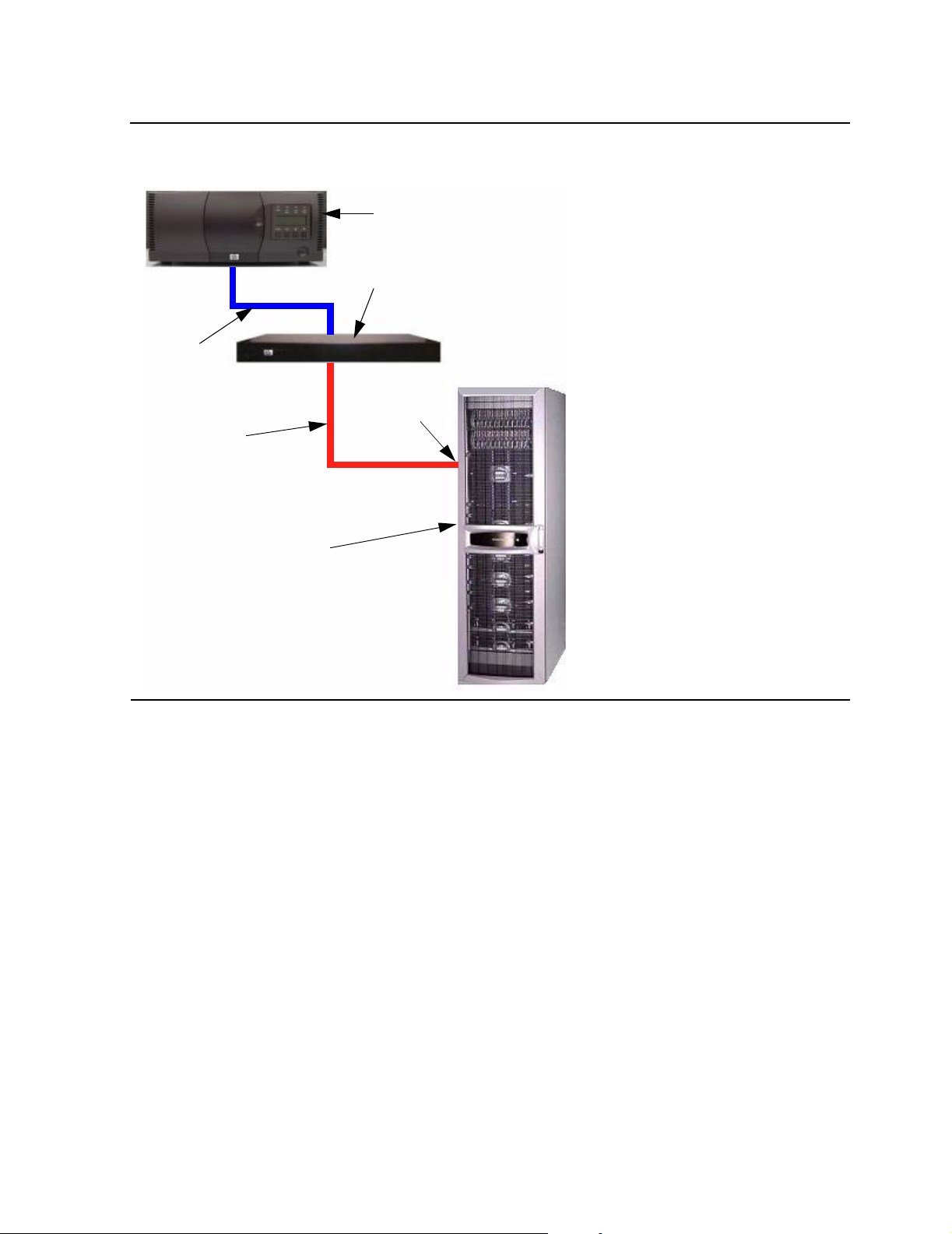
Figure 1-1 shows a Fibre Channel to SCSI Router connecting a tape drive to the Fibre
Channel ServerNet adapter (FCSA) on a NonStop NS-series server.
M8201R Fibre Channel to SCSI Router Installation and User’s Guide—529971-005
1-1
Page 16
Overview of the Fibre Channel to SCSI Router
Figure 1-1. Hardware Configuration
Tape Drive
Fibre Channel to
SCSI Router
SCSI
Cable
High Performance for Faster Backups
Fiber
FCSA
Cable
NonStop
NS-Series
Server
High Performance for Faster Backups
Support for 2 gi gabit s/seco nd F ibre C h annel e nables significantly faster ta pe r eads a nd
writes, which in turn speed operations for backup and restore. The Fibre Channel to
SCSI router backups and restores existing data in significantly less time or increasingly
larger data sets within the customers’ current backup window.
M8201R Fibre Channel to SCSI Router Installation and User’s Guide—529971-005
1-2
Page 17

Overview of the Fibre Channel to SCSI Router
Supported Storage Devices
The Fibre Channel to SCSI router can be configured with one of these storage
devices:
CTL700 tape library
•
N152xA tape drive
•
CT9840-x tape drives
•
525x tape drives
•
524x tape drives
•
524x ACL tape drives
•
Note. The Fibre Channel to SCSI router requires a firmware upgrade when it is used to
connect a N1528A, N1529A, or N1523A tape drive to a NonStop NS-series server.
Data Connections
Supported Storage Devices
The Fibre Channel to SCSI router has two types of data connections:
A SCSI High Voltage Differential (HVD) port that connects to a supported
•
storage device
A Fibre Channel port that connects to the Fibre Channel ServerNet adapter
•
(FCSA) on a NonStop NS-series server
SCSI Ports
The Fibre Channel to SCSI router has two Narrow/Wide Fast/Ultra-3 SCSI buses. Both
are Ultra SCSI for data transfer up to 40 megabytes/second per HVD bus.
Fibre Channel Port
The Fibre Channel to SCSI router has a 2 gigabits/second Fibre Channel port
and maximum throughput of 160 megabytes/second.
Power Requirements and Physical Specifications
For the power requirements and physical specifications for the Fibre Channel to SCSI
router, refer to Appendix A, Product Specifications.
M8201R Fibre Channel to SCSI Router Installation and User’s Guide—529971-005
1-3
Page 18

Overview of the Fibre Channel to SCSI Router
Power Requirements and Physical Specifications
M8201R Fibre Channel to SCSI Router Installation and User’s Guide—529971-005
1-4
Page 19

2 Getting Started
This section includes:
Location 2-1
Unpacking the Box 2-1
Mounting the Fibre Channel to SCSI Router on a Desktop 2-2
Mounting the Fibre Channel to SCSI Router in a Rack 2-2
This section describes how to install the Fibre Channel to SCSI router and what to
consider when unpacking the unit for the first time. The Fibre Channel to SCSI router
can be set up as either on a desktop or in a rack.
Before physically installing the Fibre Channel to SCSI router, consider carefully the
location for the unit installation, the intended use of the unit, and the type of devices to
which the unit will be attached.
Caution. When installing the Fibre Channel to SCSI router, use only the screws and other
hardware provided in the shipping container for the router. Using alternate hardware might
cause damage to the unit.
Location
The Fibre Channel to SCSI router can be placed on a desktop or mounted in a 19-inch
rack depending on the specific requirements of the installation.
The operati ng environment should meet the requirements listed in Physical
Specifications. If you plan to use the Fibre Channel to SCSI router on a desk top,
attach the stick-on feet to the bottom of the unit.
Note. The Fibr e C hannel to SCS I router has cooling fans mounted inside the enclosure and
air intake vents on the front of the enclosure. T he rear exhaus t ve nts and the front inta k e v ents
should rem ain clear of ob s tr uc t ions to ensure proper air flo w.
Unp acking the Box
Unpack the shipping container of the Fibre Channel to SCSI router in an area clear of
any clutter:
1. Remove all items from the shipping container. Check each item for any damage.
Keep the Fibre Channel to SCSI router in the protective bag until you are ready to
install it.
2. Make sure you received all the equipment you ordered. If an item is missing,
contact your sales representative immediately.
M8201R Fibre Channel to SCSI Router Installation and User’s Guide—529971-005
2-1
Page 20

Getting Started
Mounting the Fibre Channel to SCSI Router on a
Desktop
Mounting the Fibre Channel to SCSI Router on a Desktop
To mount the Fibre Channel to SCSI router on a desktop:
1. Remove the Fibre Channel to SCSI router from the protective bag.
2. Attach the stick-on feet to the bottom of the unit.
3. Place the Fibre Channel to SCSI router on the table or desktop.
Mounting the Fibre Channel to SCSI Router in a Rack
Two methods are available to install the Fibre Channel to SCSI router in a rack, one
method using ear brackets and the other using rails. Before beginning installation,
review the installation procedures appropriate for the mounting materials included in
the shipping container of the product you received. When familiar with the installation
procedure, follow the steps indicated to mount the Fibre Channel to SCSI router into a
19-inch rack using these provided mounting materials:
One Fibre Channel to SCSI router
•
Two ear brackets (or two slides rails with two extension brackets)
•
A bag of mounting screws (eight #M6x12 Phillips screws and four #6-32x.312
•
Phillips screws)
Required Tools
Phillips screwdriver (#2 size)
Installation Procedure With Ear Brackets
1. Remove the Fibre Channel to SCSI router from the protective bag.
2. Determine where the Fibre Channel to SCSI router should be mounted.
3. Remove any blanking panels and other equipment from the chosen rack location.
Note. To ensure proper airflow, place the Fibre Channel to SC SI router so the inta k e and
exhaust vents remain clear of obstructions.
M8201R Fibre Channel to SCSI Router Installation and User’s Guide—529971-005
2-2
Page 21
Getting Started
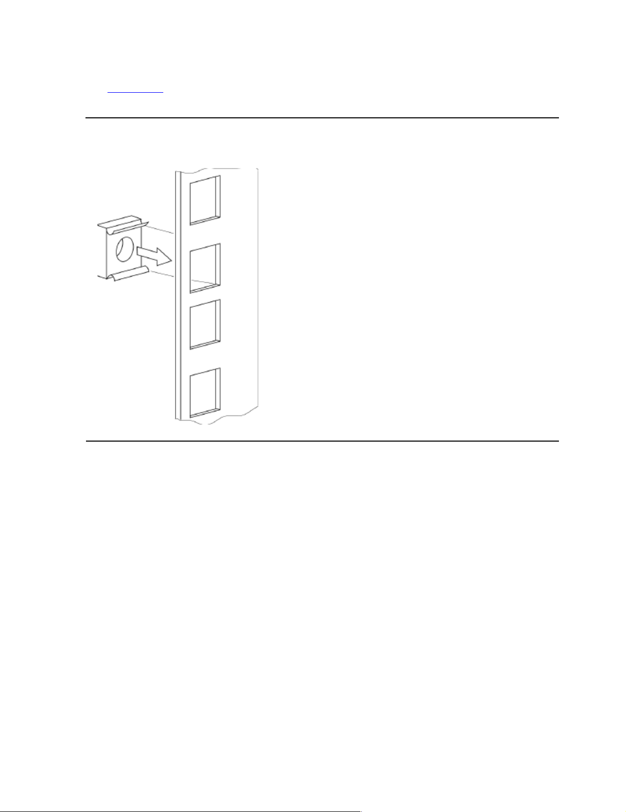
4. Install the cage nuts on the vertical mounting rails of the rack cabinet, as shown in
Figure 2-1.
Figure 2-1. Installing Cage Nuts
Installation Procedure With Ear Brackets
M8201R Fibre Channel to SCSI Router Installation and User’s Guide—529971-005
2-3
Page 22
Getting Started
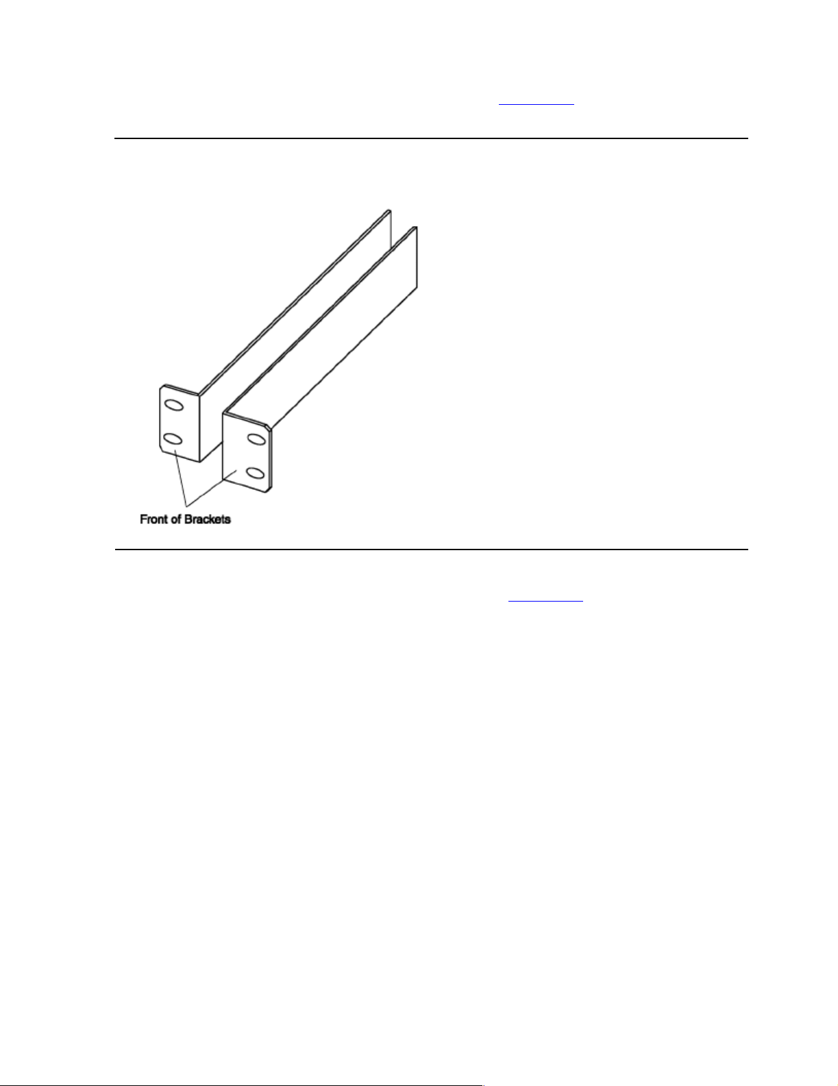
5. Locate the front of the ear brackets, as shown in Figure 2-2.
Figure 2-2. Locating Front of Ear Brackets
Installation Procedure With Ear Brackets
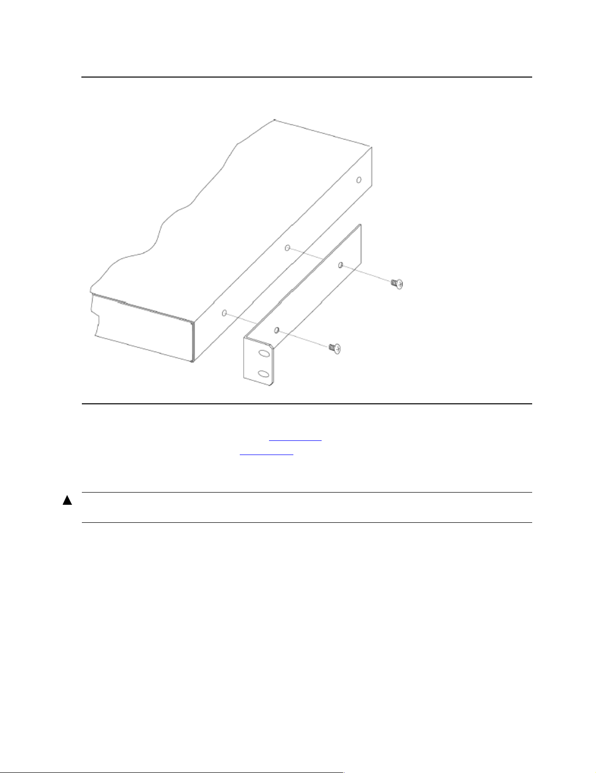
6. Attach the ear brackets to the Fibre Channel to SCSI router, using two of the #6-
32x.312 Phillips screws on each side as shown in Figure 2-3 on page 2-5. Position
the front of each bracket next to the end of the Fibre Channel to SCSI router that
will be facing out of the rack.
7. Tighten the screws securely.
M8201R Fibre Channel to SCSI Router Installation and User’s Guide—529971-005
2-4
Page 23
Getting Started
Figure 2-3. Attachi ng Ear Brackets
Installation Procedure With Ear Brackets
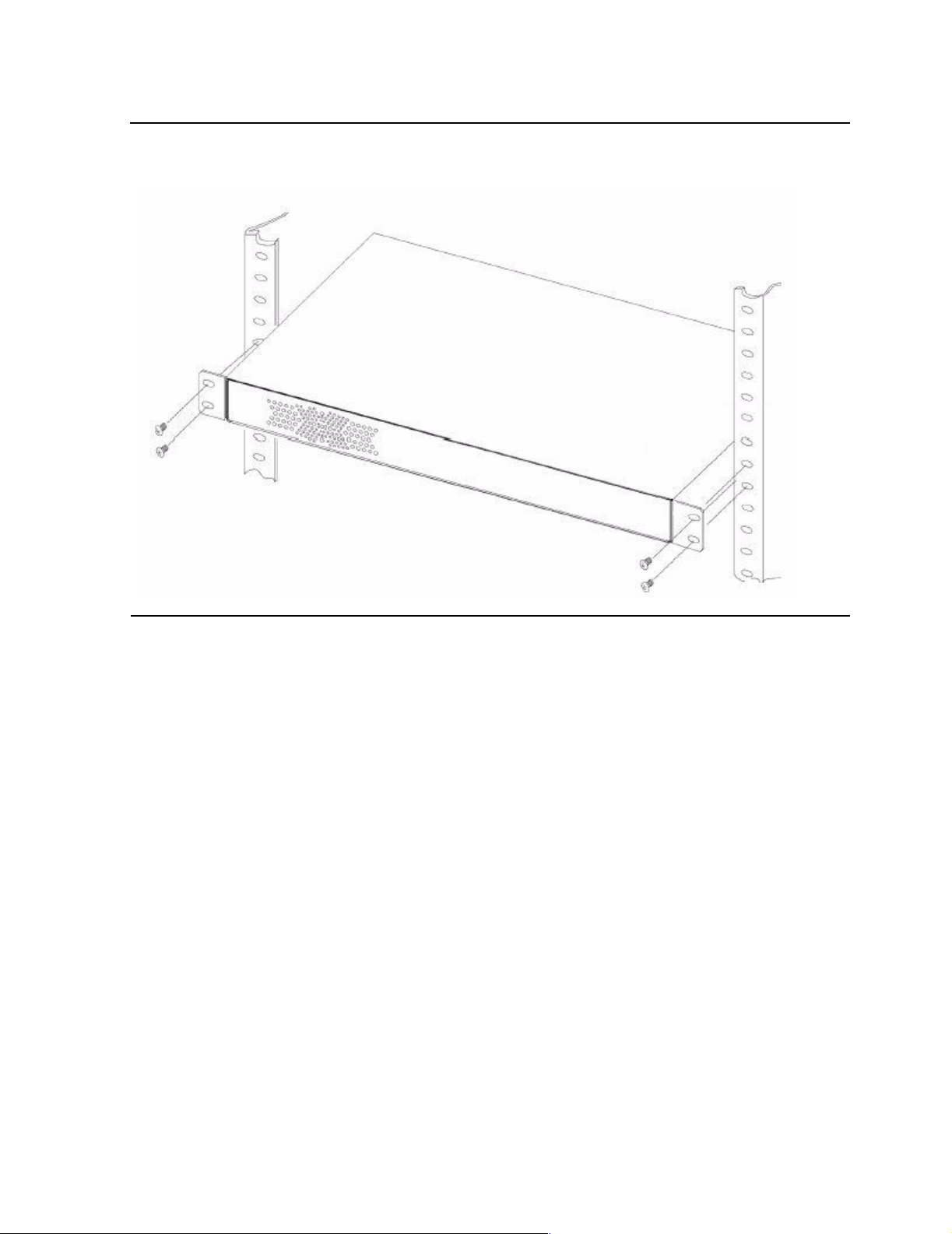
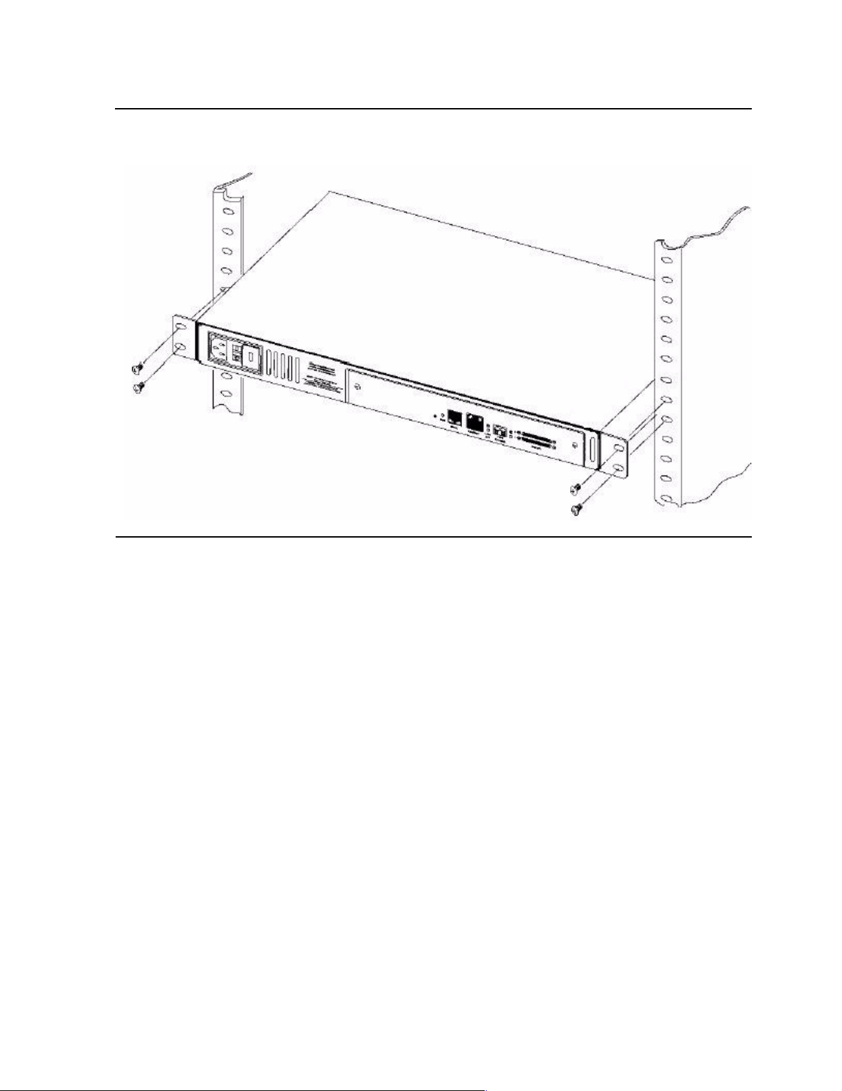
8. If you are mounting the Fibre Channel to SCSI router in the rack with the ports
facing inside the rack (shown in Figure 2-4 on page 2-6) or with the ports facing
outside the ra ck (shown in Figure 2-5 on page 2-7), attach the fron t of the moun ting
brackets to the rack using two of the #M6x12 Phillips screws for the front of each
ear bracket. Tighten the screws securely.
WA RNING. To reduce injury or eq uipment dam age, the mounting brackets must be level. I f t he
brackets ar e not level, the Fibre Channel t o SCSI rout er c annot be installed correctly.
M8201R Fibre Channel to SCSI Router Installation and User’s Guide—529971-005
2-5
Page 24
Getting Started
Figure 2-4. Mounting at Front of Rack
Installation Procedure With Ear Brackets
M8201R Fibre Channel to SCSI Router Installation and User’s Guide—529971-005
2-6
Page 25
Getting Started
Figure 2-5. Mounting at Back of Rack
Installation Procedure With Ear Brackets
M8201R Fibre Channel to SCSI Router Installation and User’s Guide—529971-005
2-7
Page 26

Getting Started
Installation Procedure With Ear Brackets
M8201R Fibre Channel to SCSI Router Installation and User’s Guide—529971-005
2-8
Page 27

3
Installing the Fibre Channel to SCSI Router for the NonStop NS-Series Server
This section includes:
Installation 3-1
Installation
1. Connect the small end of the SCSI cable to the Fibre Channel to SCSI router on
port 0. For the port location, see Figure 3-3 on page 3-3.
Note. In this exam ple port 0 is being used to co nnect the tape dr iv e. Both ports on the
Fibre Ch annel to SCS I ro ut er are available for use if needed.
Table 3-1. SCSI Cable Part Numbers and Descriptions
Product
Number
520-001 529794 -001 CB A, 1 m et er, VH D CI 68P to HD 68P, H VD SCSI Cable
520-003 529795 -001 CB A, 3 m et er, VH D CI 68P to HD 68P, H VD SCSI Cab l e
520-010 529796-001 CBA, 10 meter, VHDCI 68P to HD 68P, HVD SCSI Cable
520-015 529797-001 CBA, 15 meter, VHDCI 68P to HD 68P, HVD SCSI Cable
520-020 529798-001 CBA, 20 meter, VHDCI 68P to HD 68P, HVD SCSI Cable
520-023 529799-001 CBA, 23 meter, VHDCI 68P to HD 68P, HVD SCSI Cable
Part
Number Description
M8201R Fibre Channel to SCSI Router Installation and User’s Guide—529971-005
3-1
Page 28

Installing the Fibre Channel to SCSI Router for the
NonStop NS-Series Server
Figure 3-1. SCSI Cable
Installation
2. Tighten the screws by hand to secure the cable to the unit. Do not use a
screwdriver.
M8201R Fibre Channel to SCSI Router Installation and User’s Guide—529971-005
3-2
Page 29

Installing the Fibre Channel to SCSI Router for the
NonStop NS-Series Server
3. Connect one end of the fiber cable to the small form-factor pluggable (SFP) on the
unit. See Figure 3-3 for the location.
4. Attach the power cord to the AC power receptacle on the Fibre Channel to SCSI
router. See Figure 3-3 for the location. Then plug the other end into an AC power
outlet.
Note. The router does not have protectio n against ligh tn ing surges. Cu s t om ers in high risk
areas sho uld use external surge prot ec t ion rated for use in their locat ion and be ab le t o handle
the powe r demand of the router.
Figure 3-2. Front View of the Fibre Channel to SCSI Router
Installation
Figure 3-3. Rear View of the Fibre Channel to SCSI Router
Port 0
Port 1
AC Power
Receptacle
Power
Switch
Small Form-Factor
Pluggable (SFP)
M8201R Fibre Channel to SCSI Router Installation and User’s Guide—529971-005
3-3
Page 30

Installing the Fibre Channel to SCSI Router for the
NonStop NS-Series Server
5. Connect the larger end of the SCSI cable to SCSI port 1 on the rear panel of the
tape drive. See Figure 3-5 for the location.
Figure 3-4. Front View of the Tape Drive
Installation
Figure 3-5. Rear View of the Tape Drive
AC Power Receptacle Port 2 Port 1
Power Switch
Note. Tape drives are preconfigured to SCSI ID 5.
M8201R Fibre Channel to SCSI Router Installation and User’s Guide—529971-005
3-4
Page 31

Installing the Fibre Channel to SCSI Router for the
NonStop NS-Series Server
6. Tighten the screws by hand to secure the cable to the unit. Do not use a
screwdriver.
7. Connect the supplied differential terminator to SCSI port 2. See Figure 3-5 on
page 3-4 for the location.
8. Tighte n the screws by han d to secure the term inator to the tap e driv e. Do not use a
screwdriver.
9. Attach the power cord to the AC power receptacle on the tape drive. See
Figure 3-5 for the location. Then plug the other end into an AC power outlet.
Note. The ta pe drive does not have pro t ection against lightning surges. Customers in high r isk
areas sho uld use external surge prot ec t ion rated for use in their locat ion and be ab le t o handle
the powe r demand of the tap e drive.
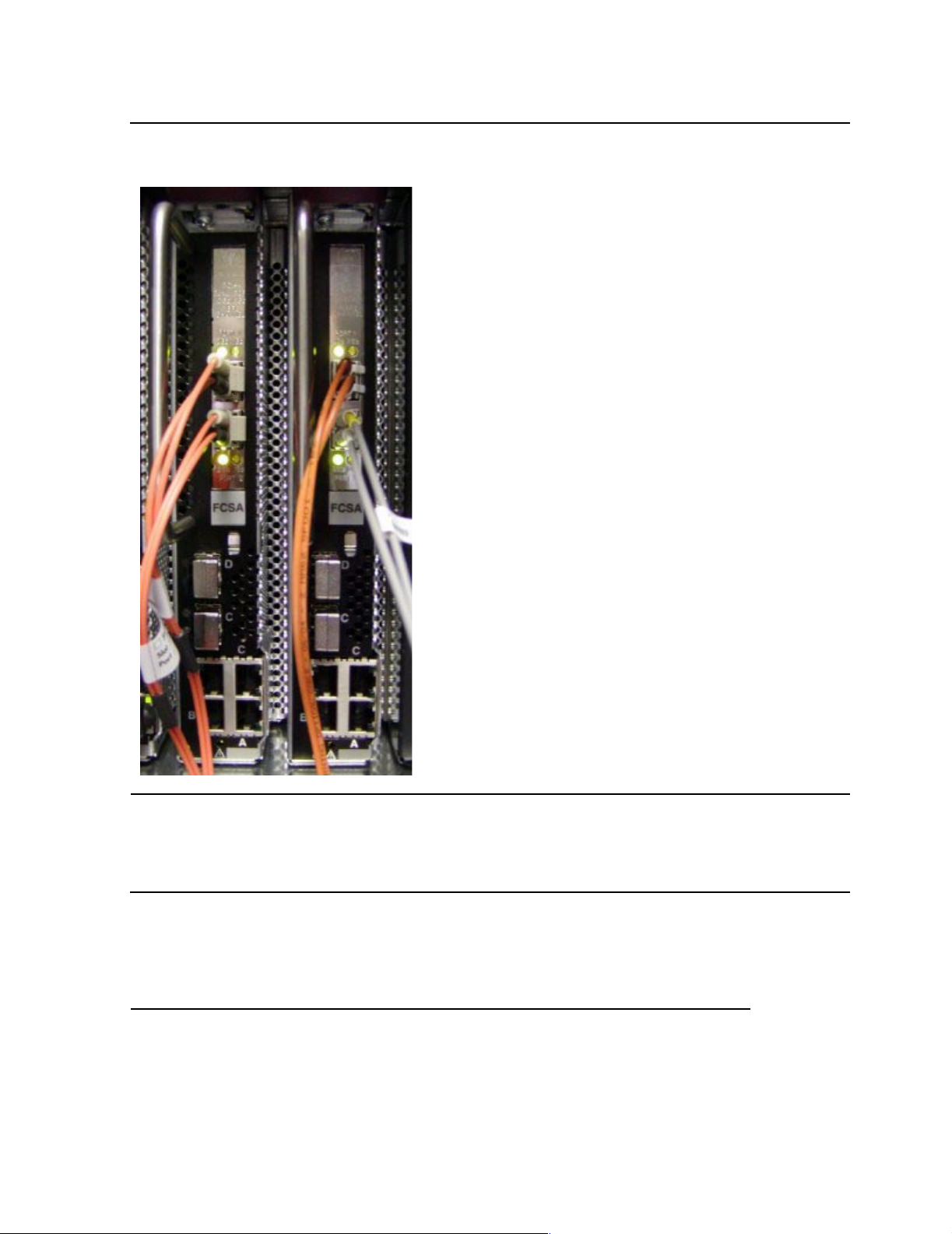
10. Connect the other end of the fiber cable to the Fibre Channel ServerNet adapter
(FCSA) on the NonStop NS-series server. For the location of the FCSA, see
Figure 3-6 on page 3-6.
Installation
M8201R Fibre Channel to SCSI Router Installation and User’s Guide—529971-005
3-5
Page 32
Installing the Fibre Channel to SCSI Router for the
NonStop NS-Series Server
Figure 3-6. View of Two FCSAs at the Rear of Server
Installation
The fiber cable is a multimode/short wave fiber-optic cable. This cable is normally
an orange color.
Table 3-2. Fiber Cables
Connector Fiber Cable Fiber Cable Distance
LC - LC 50/125 µm 2-300 meters (6.56-984.25 feet)
LC - LC 62.5/125 µm 3-150 meters (9.84-492.13 feet)
M8201R Fibre Channel to SCSI Router Installation and User’s Guide—529971-005
3-6
Page 33

Installing the Fibre Channel to SCSI Router for the
NonStop NS-Series Server
11. Power on the tape drive. For the power switch location, see Figure 3-4 on
page 3-4. Then wait for it to perform its power-on-self-test (POST).
12. Power on the router, and then wait for it to perform its power-on-self-test (POST).
Installation
M8201R Fibre Channel to SCSI Router Installation and User’s Guide—529971-005
3-7
Page 34

Installing the Fibre Channel to SCSI Router for the
NonStop NS-Series Server
Installation
M8201R Fibre Channel to SCSI Router Installation and User’s Guide—529971-005
3-8
Page 35

4
Configuring the Fibre Channel to SCSI Router for the NonStop NS-Series Server
This section includes:
Configuration 4-1
Configuration
1. In SCF, issue this command:
SCF> ADD TAPE $tape, SENDTO STORAGE, LOCATION (group, module,
slot), SAC sac-id, PORTNAME 64-bit-portname, LUN lun-id
Example:
SCF> ADD TAPE $TAPE1, SENDTO STORAGE, LOCATION (110,2,3), SAC
1, PORTNAME 100000E00C00F000, LUN 1
Note. The LUN (logical unit number) in SCF should be 1 for the tape drive that is on bus 0 and
3 for the tape driv e that is on bus 1.
Note. PORTNAM E in SCF corres ponds to the W W P name of the router. This name is located
on the bac k o f the device.
The Fibre Channel to SCSI router can also be connected to a tape library.
Table 4-1 shows the SCSI ID, router port number, and the LUN address for a tape
library and a tape drive.
Table 4-1. LUN Mapping Table for the Fibre Channel to SCSI Router
DEVICE SCSI ID Router PORT LUN ADDRESS
Tape library 3 0 LUN 0
Tape drive 5 0 LUN 1
Tape library 3 1 LUN 2
Tape drive 5 1 LUN 3
M8201R Fibre Channel to SCSI Router Installation and User’s Guide—529971-005
4-1
Page 36
Configuring the Fibre Channel to SCSI Router for
the NonStop NS-Series Server
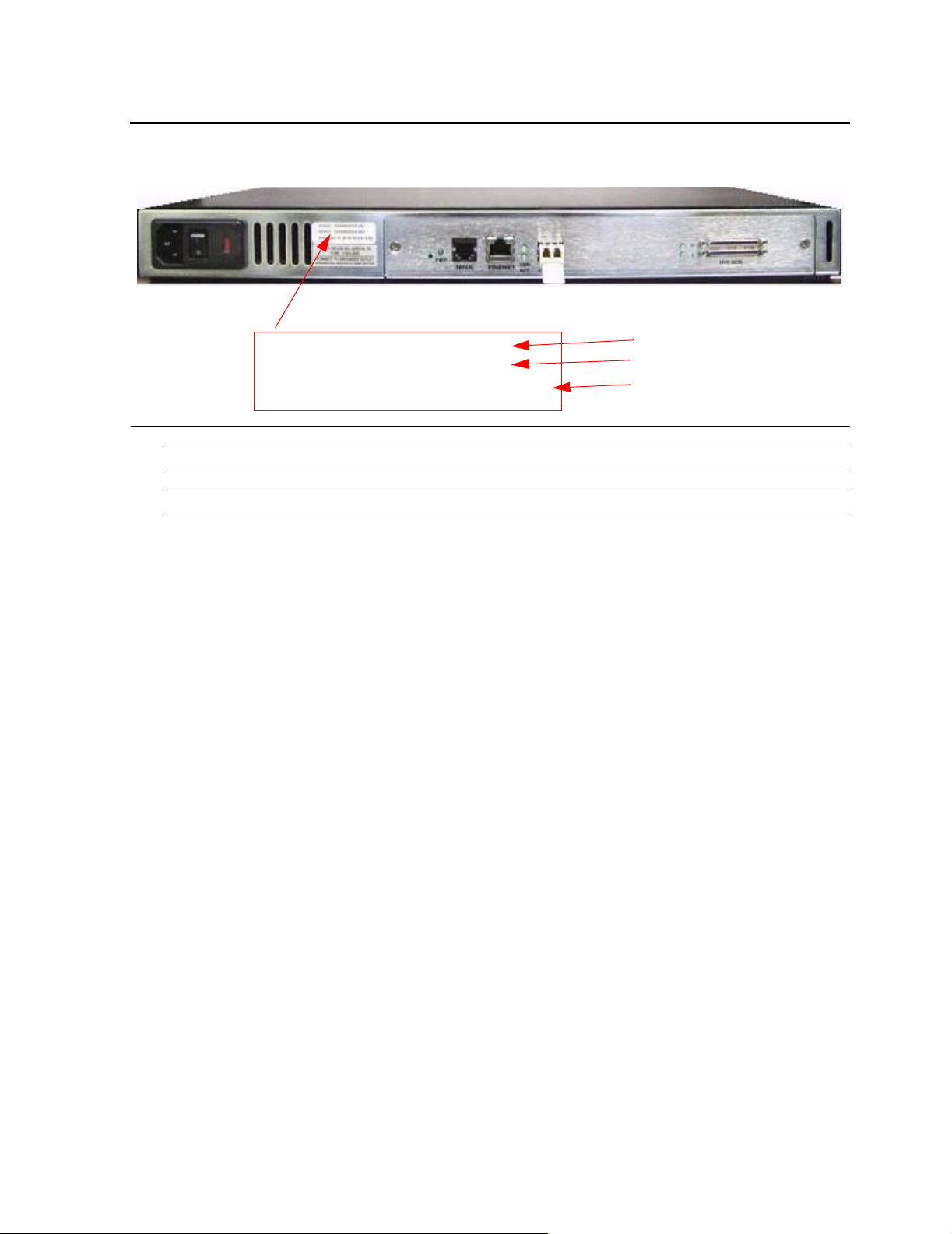
Figure 4-1. Rear View of the Fibre Channel Router
Configuration
WWNN: 100000E00200F000
WWPN: 100000E00C00F000
ENET MAC ID: 00:E0:02:00:00:XY
WWN Name
WWP Name
Ethernet MAC ID
(Physical Address)
Note. WWN s tan ds fo r w orldwide nam e.
Note. WWP stan ds f or worldwide port.
2. To start the tape drive on the server, issue this command in SCF:
SCF> START TAPE $tape
Example:
SCF> START TAPE $TAPE1
For complete details about the ADD and START commands, including command
syntax, see the SCF Reference Manual for the Storage Subsystem.
M8201R Fibre Channel to SCSI Router Installation and User’s Guide—529971-005
4-2
Page 37

5
Troubleshooting the Fibre Channel to SCSI Router
This section includes:
Visual Inspection 5-1
Te chnical Support 5-1
Indicators 5-2
This section guides the user through some of the basic methods of identifying faults in
the setup and configuration of the unit.
Most problems occur in the initial installation. In general, it is wise to check all
connections and review the configuration before proceeding with further trouble
analysis. Simplify the inst allation i f possible, redu cing it to the most basic configu ration .
Then add elements one at a time and verify the operation at each step.
Visual Inspection
To assure that the installation of the Fibre Channel to SCSI router has been
completed correctly:
1. Check that all devices are powered up.
2. Check that all cords are plugged in tightly, and there are no bent pins.
3. Check the LEDs. No amber lights should be illuminated.
4. Check the fiber cables to ensure the connectors are properly installed
between the Fibre Channel to SCSI router and the server.
5. Check that each device has the correct SCSI ID.
Technical Support
If the Fibre Channel to SCSI router is not functioning properly, contact your
service provider.
M8201R Fibre Channel to SCSI Router Installation and User’s Guide—529971-005
5-1
Page 38
Troubleshooting the Fibre Channel to SCSI Router
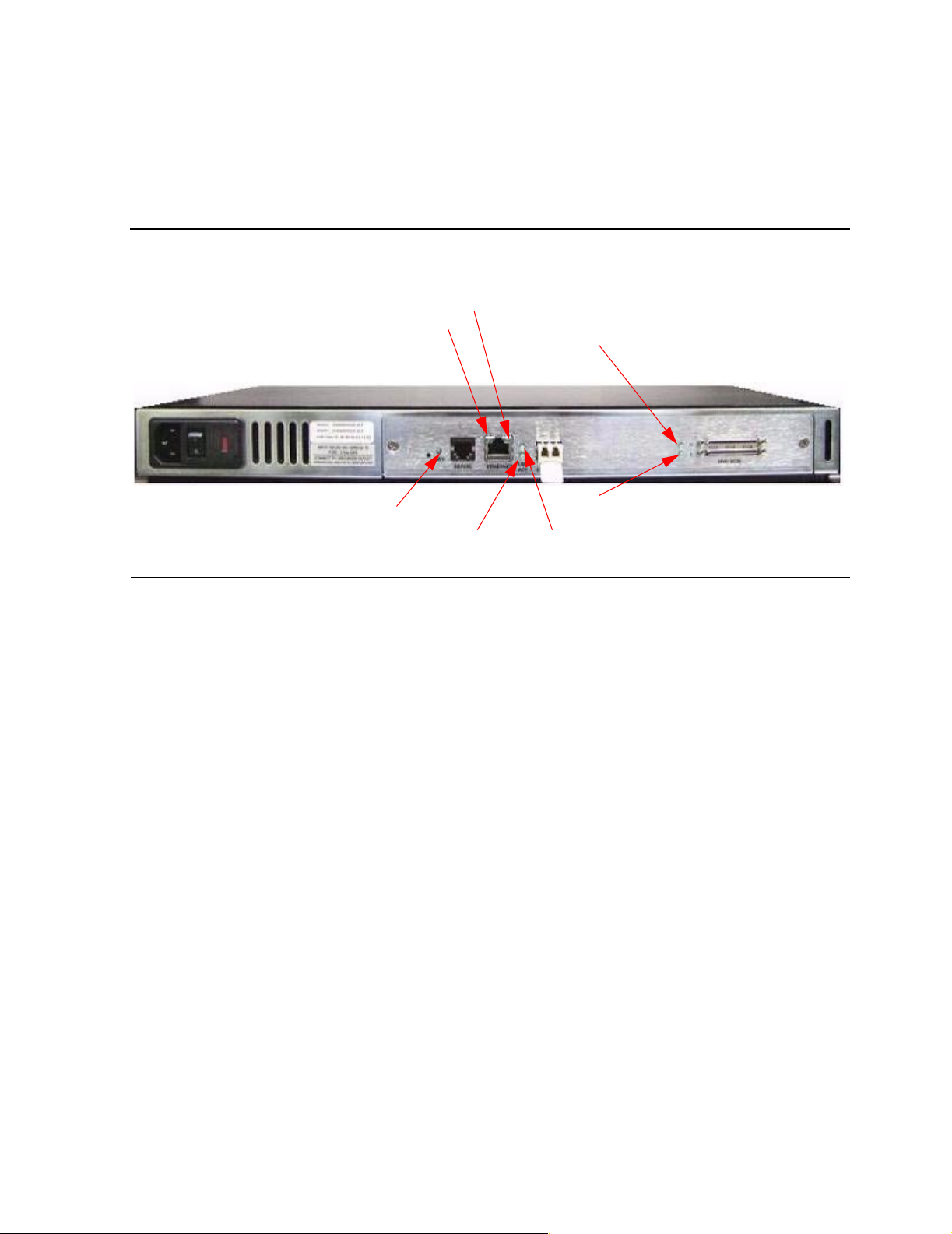
Indicators
The Fibre Channel to SCSI router is equipped with rear panel LED indicators for
monitoring overall unit status.
Figure 5-1. LED Indicators
Indicators
Ethernet Activity
Ethernet Link Status
Fibre Channel Activity
The Fibre Channel to SCSI router has these LEDs:
Power and Fault (Pwr)—This indicator is a bicolor LED. When green, this indicator
•
shows that power is currently active. Lack of power indication suggests that the
unit is turned off, a problem occurred with the power supplied to the unit, or an
internal problem occurred with the unit. This indicator is amber when the Fibre
Channel to SCSI router detects a fault condition. Faults can occur as a result of
Power On Self Test (POST) failure or operational failures. It is normal for this
indicator to flash on when the unit is power ed up or rese t. If the fault i ndicator sta ys
lit, contact your service provider.
Power
HVD SCSI Activity for Bus 0
HVD SCSI Activity for Bus 1
Fibre Channel Link Status
Fibre Channel (L nk/Act)—W hen lit green, the upper indicator signifies a good Fibre
•
Channel link on the por t. When li t gree n, the lower ind icator sign i fies Fibre Ch annel
port activity. If the Link indicator fails to light at all or if the Activity indicator stays
continually lit without corresponding SCSI bus activity, there might be a problem
with the Fibre Channel configuration. Verify the Fibre Channel configuration.
SCSI Bus (0 , 1)—When lit green, the upper indicator signifies a good Fibre
•
Channel link on the por t. When li t gree n, the low er ind icator sign i fies Fibre Ch annel
port activity. If the Link indicator fails to light at all or if the Activity indicator stays
continually lit without corresponding SCSI bus activity, there might be a problem
with the Fibre Channel configuration. Verify the Fibre Channel configuration.
M8201R Fibre Channel to SCSI Router Installation and User’s Guide—529971-005
5-2
Page 39

6
Hardware Replacement Procedures
This section includes:
Tape Drive and Fibre Channel to SCSI Router Replacement
6-1
Tape Drive and Fibre Channel to SCSI Router
Replacement
These procedures can be done for any tape drive that is connected to the Fibre
Channel to SCSI router. For information about what tape drives can be connected to a
Fibre Channel to SCSI router, see Supported Storage Devices on page 1-3. In these
procedures the N1525A tape drive is used.
Tape Drive Replacement
1. Perform a forced reset on the tape drive in SCF by entering in the following
command:
SCF> RESET TAPE1, FORCED
2. Power off the tape drive by pressing the power switch. For the location, see
Figure 6-1.
Figure 6-1. Location of the Power Switch on the Tape Drive
Power Switch
M8201R Fibre Channel to SCSI Router Installation and User’s Guide—529971-005
6-1
Page 40
Hardware Replacement Procedures
Fibre Channel to SCSI Router Replacement
3. Unplug the power cord from the AC power outlet, and then unplug the other end
from the tape drive’s AC power receptacle.
4. Disconnect the SCSI cable from port 1 by unscrewing the screws by hand. Do not
use a screwdriver.
5. Disconnect the differential terminator from port 2 by unscrewing the screws by
hand. Do not use a screwdriver.
6. Place the old tape drive aside.
7. Connect the new tape d ri ve. Refer to section 3 Insta l ling the F ibre Chan nel to SC SI
Router for the NonStop NS-Series Server when installing a new tape drive.
8. Power cycle the Fibre Channel to SCSI router by powering it off and then on.
9. Start the tape drive in SCF by entering in the following command:
SCF> START TAPE $TAPE1
Fibre Channel to SCSI Router Replacement
1. Perform a forced reset on the tape drive in SCF by entering in the following
command:
SCF> RESET TAPE1, FORCED
2. Power off the tape drive by pressing the power switch. See Figure 6-1 for the
location.
3. Power off the Fibre Channel to SCSI router.
4. Unplug the power cord from the AC power outlet, and then unplug the other end
from the AC power receptacle on the Fibre Channel to SCSI router.
5. Disconnect the fiber cable from the small form-factor pluggable (SFP) on the unit.
Figure 6-2. Rear View of the Fibre Channel to SCSI Router
Port 0
Port 1
AC Power
Receptacle
Power
Switch
Small Form-Factor
Pluggable (SFP)
6. Disconnect the SCSI cable from the Fibre Channel to SCSI router on port 0. If
there is another tape drive connected to port 1, disconnect that device also.
M8201R Fibre Channel to SCSI Router Installation and User’s Guide—529971-005
6-2
Page 41

Hardware Replacement Procedures
7. Place the old Fibre Channel to SCSI router aside.
8. Install the new Fibre Channel to SCSI router. Refer to section 3 Installing th e Fibre
Channel to SCSI Router for the NonStop NS-Series Server when installing a new
Fibre Channel to SCSI router.
9. Enter in the following SCF command:
SCF> ALTER TAPE TAPE1, WWN 100000E00200F00
The WWN (Worldwide Name) is on the rear of the Fibre Channel to SCSI Router
as shown in Figure 6-3 on page 6-3.
Figure 6-3. Rear View of the Fibre Channel Router
Fibre Channel to SCSI Router Replacement
WWNN: 100000E00200F000
WWPN: 100000E00C00F000
ENET MAC ID: 00:E0:02:00:00:XY
WWN Name
WWP Name
Ethernet MAC ID
(Physical Address)
10. Power on the tape drive. See Figure 6-1 on page 6-1 for the power switch location.
Then wait for it to perform its power-on-self-test (POST).
11. Start the tape drive in SCF by entering in the following command:
SCF> START TAPE $TAPE1
M8201R Fibre Channel to SCSI Router Installation and User’s Guide—529971-005
6-3
Page 42

Hardware Replacement Procedures
Fibre Channel to SCSI Router Replacement
M8201R Fibre Channel to SCSI Router Installation and User’s Guide—529971-005
6-4
Page 43

A Product Specifications
Fibre Channel to SCSI Router
Figure A-1. Fibre Channel to SCSI Router
17 inches (43 centimeters)
Table A-1. Dimensions of the Fibre Channel to SCSI Router
Specification Value
Weight 9 pounds (4 k ilograms)
Widt h 17 inches (43 centi m eters)
Height 1.72 inches (4.4 centimeters)
Depth 10.75 inches (27 centimeters)
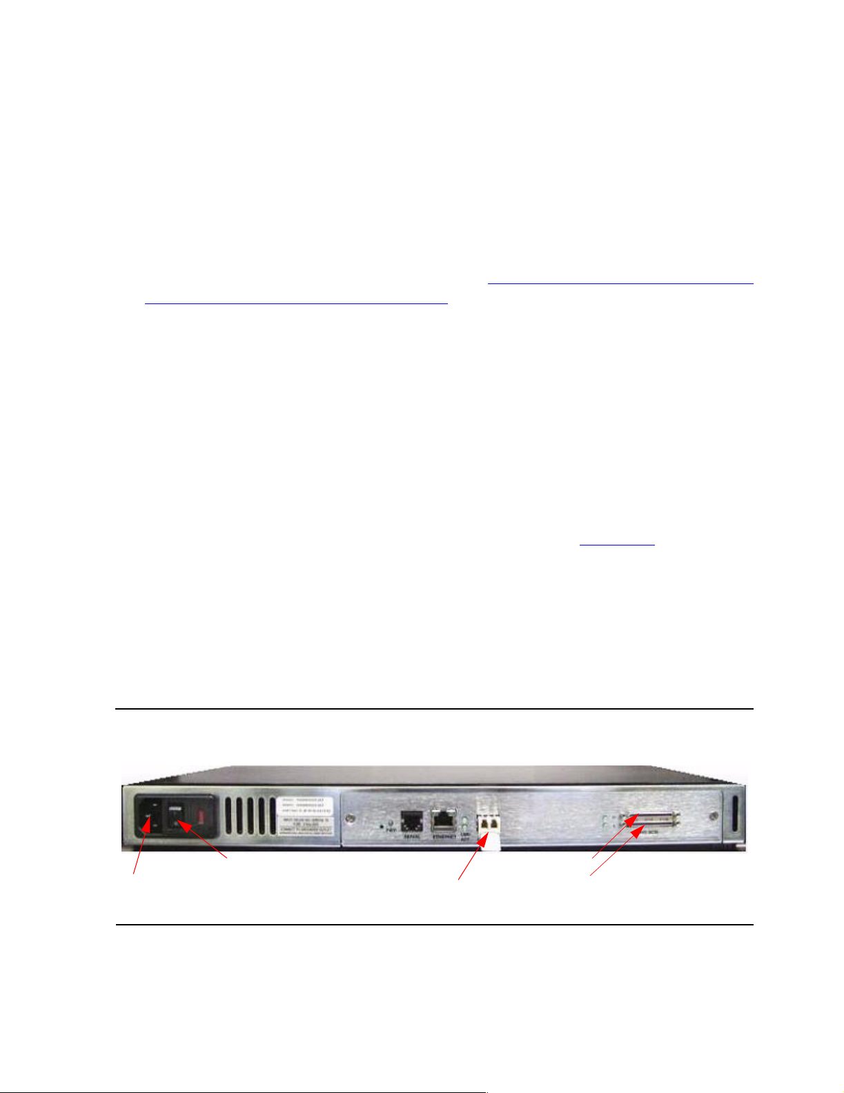
Figure A-2. Rear Panel Components
AC Power
Receptacle
M8201R Fibre Channel to SCSI Router Installation and User’s Guide—529971-005
Power
Switch
LEDs
A-1
Fiber Cable
Port
SCSI
Cable
Ports
Page 44

Product Specifications
Power Requirement s
WA RNING. The Fibre Channel to SCSI router does not have protection against lightning
surges. F or t his reason, for cu s to m ers in a high risk area, use ext ernal surge protection rat ed
for use in your location and be able to handle the power requirements of the tape drive
enclosure.
Power
100 to 240 V ac, auto sensing
•
50/60 Hertz, 1.0 ampere
•
Physical Specifications
Internal power supply with detachable power cord
•
Fibre Channel link status and activity LEDs
•
Power Requirements
SCSI bus activity LEDs
•
Power/Fault LED
•
Air flow with internal fan
•
Rackmount or desktop enclosure
•
Power switch
•
Operating Environment
0 to 50 degrees celsius
•
5 to 80 percent relative humidity (noncondensing)
•
Non-operating Environment
-40 to +55 degrees celsius
•
0 to 92 percent relative humidity (noncondensing)
•
Connection Supported
The only connection supported is a Fibre Channel ServerNet adapter (FCSA) on a
NonStop NS-series server.
M8201R Fibre Channel to SCSI Router Installation and User’s Guide—529971-005
A-2
Page 45

B Using the Serial Interface
This section describes specific configuration options available for the serial interface.
The Fibre Channel to SCSI router allows the user to access Ethernet configuration
settings through the serial interface.
Serial Port Connection
The RJ-11 connector on the back panel of the Fibre Channel to SCSI router provides a
serial port that is compatible with RS-232 signaling levels. The Fibre Channel to SCSI
router is designed to communicate with a terminal or any operating system utilizing a
terminal emulato r. The baud rate, d at a bi t s, stop bit s , p ar ity, and flow contr ol of bot h the
router and the host system must use the same settings. The autobaud feature
described in the next subsection provides an effective method to set the baud rate of
the router and host system.
Figure B-1. Fibre Channel to SCSI Router Serial Port
Serial Port
Autobaud Feature
The autobaud feature automatically confi gures the baud rate on the Fibre Channel to
SCSI router. Once you set the baud rate in the terminal emulator, wait until the Fibre
Channel to SCSI router completes the power-on self test (POST) and then the
Firmware Initialization process. This can take up to 90 seconds, during which time the
POST and initialization information might or might not be visible on the terminal or
terminal emulator. After this process has completed, press the Enter key slowly 7 or 8
times (or type shift-z) and the Fibre Channel to SCSI router automatically detects the
baud rate being used by the serial port. The baud rate is then saved in the Fibre
Channel to SCSI router’s configuration and is retained through future power cycles.
Note. Pressing the Enter key before the POST has completed is of no benefit to the autobaud
feature. Wait unt il both the POS T and the Firmw are Initializat ion processes have complet ed
before pressing the Enter key. This might take up to 90 seconds.
The baud rate used by the terminal or terminal emulator must be 9600, 19200, 38400,
57600, or 115200 for the autobaud feature to recognize it. The Fibre Channel to SCSI
router does not function properly at any other baud rate.
M8201R Fibre Channel to SCSI Router Installation and User’s Guide—529971-005
B-1
Page 46

Using the Serial Interface
Setting Up Serial Port Communications
Leave the Fibre Channel to SCSI router turned off until you have set up the serial port
communications on your host computer unless serial I/O was previously established
and is currently running.
The Fibre Channel to SCSI router is designed to communicate with a terminal or any
operating system utilizing a terminal emulator. For example, Windows 9x, NT 4.0, or
2000 operating systems can use hyper terminal. Check that the baud rate, data bits,
stop bits, parity, and flow control are set correctly.
To set up serial communications with the Fibre Channel to SCSI router:
1. Leave power to the router turned off until you have set up the serial port
communications on your host terminal.
2. Plug the serial cable into one of the host computer’s serial ports (COM1 or COM2),
and then plug the other end of the serial cable into the router’s serial port.
3. Start the terminal emulator.
Setting Up Serial Port Communications
4. Set the terminal emulator to use the appropriate COM port.
Note. Auto Det ec t or VT 100 are th e rec ommende d s et t ings for Window s H y per Termina l
emulat ion type.
5. Specify these settings for the port:
Baud rate: 9600, 19200, 38400, 57600, or 115200
(Autobaud recognizes only these baud rates.)
Data bits: 8
Stop bits: 1
Parity: None
Flow control: None or XON/XOFF
Note. Before initially powering on the Fibre Channel to SCSI router, check that all the
Fibre Ch annel and SCSI devices are powered on first and th at th ey have finished
performing their self tests. This approach helps ensure that device discovery works
correctly.
M8201R Fibre Channel to SCSI Router Installation and User’s Guide—529971-005
B-2
Page 47

Using the Serial Interface
Ethernet Configuration
This option allows for setting up all Ethernet network settings, including IP address,
Subnet mask, IP gateway, SNMP and security settings, Ethernet mode, physical
address, and host name.
Figure B-2. Ethernet Configuration Menu
Ethernet Configuration Menu
X.XX.XX XXXXXX XXXXXX-XXX_XXXXXXXXXXXXXX
01/06/2003 08:56:22
IP Address : 192.231.36.101
Subnet Mask : 255.255.255.0
IP Gateway : 0.0.0.0
Ethernet Physical Address : 08:06:07:05:03:09
Ethernet Mode : 10/100Mbps (Auto-Neg)
Hostname :
DHCP Configuration : Disabled
Ethernet Configuration
1) Change IP Address
2) Change IP Subnet Mask
3) Change IP Gateway
4) Change Ethernet Physical Address
5) Toggle Ethernet Mode
6) Change Hostname
7) Toggle DHCP Configuration
8) Change SNMP Settings
9) Change Security Settings
X) Return to previous menu
Select 1 to change the IP address of the Fibre Channel to SCSI router. The default
•
for this setting is 192.231.36.101.
Select 2 to change the IP subnet mask for the Fibre Channel to SCSI router. The
•
default for this setting is 255.255.255.0.
Select 3 to change the IP gateway for the Ethernet network of the Fibre Channel to
•
SCSI router.
Select 4 to change the Ethernet physical address, or MAC address, of the Fibre
•
Channel to SCSI router. Ethernet physical addresses are always assigned to
Ethernet adapters by the manufacturers.
M8201R Fibre Channel to SCSI Router Installation and User’s Guide—529971-005
B-3
Page 48

Using the Serial Interface
Select 5 to toggle the Ethernet mode among these options:
•
10Mbps Only
100Mbps (half duplex) Only
100Mbps (full duplex) Only
10/100Mbps (Auto-Neg.)
Select 6 to change the hostname. This alphanumeric entry is one word up to eight
•
characters long.
Note. Do not use an uppercase Z a s a par t of th e hostname as it is th e aut obaud hot ke y used
by the Micr os oft W indows hyper terminal u til ity f or serial connections.
Select 7 to toggle the DHCP setting. This setting enables and disables support for
the Dynamic Host Configuration Protocol. When enabled, the router retrieves a
dynamic IP address from a DHCP server located on the Ethernet network that the
Fibre Channel to SCSI router is connected to.
Once DHCP is enabled, save the current configuration and reboot the router
before an IP address can be requested from the DHCP server:
Ethernet Configuration
1. Select X Return to previ ous menu.
2. Select A Save Configuration.
3. Select X Return to previ ous menu.
4. Select 4 Reboot.
After the router reboots, the Main menu appears on the serial interface. For Telnet,
a new session needs to be opened to continue configuring the router. DHCP status
can be verified from the Ethernet Configuration Menu where DHCP Configuration
is indicated as Enabled if DHCP has been successfully activated. The IP address
might also appear different than the former non-DHCP IP address.
Note. To use the DHCP feature, a DHCP server must be operational on the Ethernet
network used by the Fibre Channel to SCSI router. If the DHCP feature is used when there
is no DHCP server, the st andar d for DHCP requires that the rout er wait thre e minutes for a
response from a DHCP server before timing out.
Your DHCP server might allow you to set up a lease reservation for an IP address
by providing the server with the Ethernet MAC address of the Fibre Channel to
SCSI router. This sets the DHCP server to always provide the same IP address to
the Fibre Channel to SCSI router. This setup can be useful for remote
management of the router via Telnet or Crossroads Visual Manager. Because the
method of setting up a lease reservation varies depending on the DHCP server
being used, you should contact your network administrator for assistance.
Select 8 to access the SNMP Settings for the Fibre Channel to SCSI router,
•
including the community names for GET and SET as well as SNMP Trap settings.
For Trap settings, select the IP address of the device to send the SNMP trap
notifications.
M8201R Fibre Channel to SCSI Router Installation and User’s Guide—529971-005
B-4
Page 49

Using the Serial Interface
Select 9 to change security settings, including the user name and password. User
•
names and passwords should be unique and kept confidential. Use a combination
of letters and numbers when creating user names and passwords.
Ethernet Configuration
M8201R Fibre Channel to SCSI Router Installation and User’s Guide—529971-005
B-5
Page 50

Using the Serial Interface
Ethernet Configuration
M8201R Fibre Channel to SCSI Router Installation and User’s Guide—529971-005
B-6
Page 51

C
Configuring OSM for Monitoring the
Fibre Channel to SCSI Router
This section includes the st ep s that are needed to configure OSM so that it can mon i tor
the Fibre Channel to SCSI router.
To configure OSM for monitoring the router complete these three basic steps:
1. Connect the router to the LAN connection on the system.
2. Configure the router's IP address, user name, and password.
3. Configure the router for OSM monitoring.
You need these components:
A M8201R Fibre Channel to SCSI router
•
A system console with a hyper terminal installed
•
A serial cable
•
A system console with a serial cable port
•
Connecting the Hardware
To connect the route r to the LAN connection on t he system, make th ese conne ctions to
the Fibre Channel to SCSI router:
1. Connect the router to the FCSA on the system by using a fiber-optic cable.
2. Connect the tape drive to the router by using a SCSI cable.
Note. For more information on connecting the router and tape drive to the system, see
Installing t he Fibre Chan nel to SCSI Ro ut er f or the NonStop NS-S eries Server on
page 3-1.
3. Connect a serial cable to the system, and then connect the other end of the cable
to the serial port on the router.
Note. For more information on connecting the serial cable to the system, see Using the
Serial Interface on page B-1.
M8201R Fibre Channel to SCSI Router Installation and User’s Guide—529971-005
C-1
Page 52
Configuring OSM for Monitoring the Fibre Channel to
SCSI Router
Configuring the Fiber Channel to SCSI Router for
OSM Monitoring
Configuring the Fiber Channel to SCSI Router for OSM Monitoring
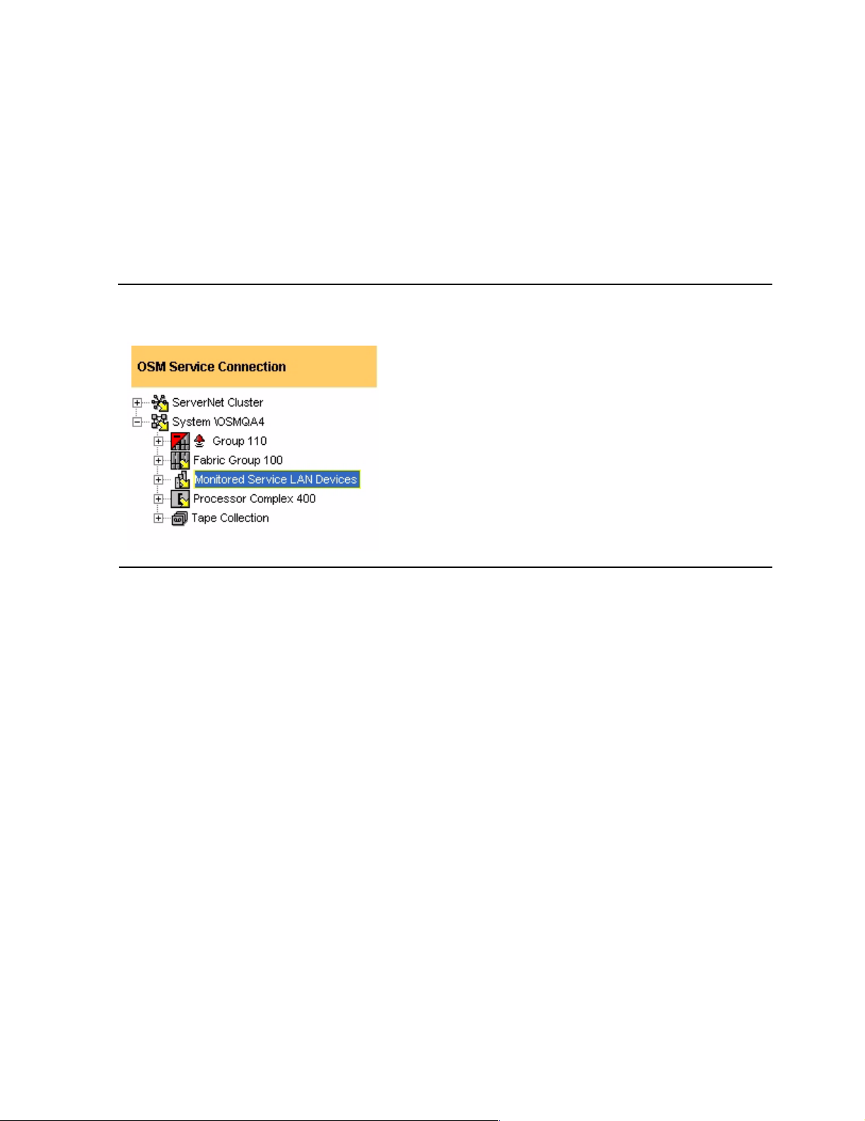
1. Open a web browser on the system.
2. Start OSM.
3. On the tree view, right-click on Monitor Service Lan Devices and select actions.
Figure C-1. OSM Tree View
M8201R Fibre Channel to SCSI Router Installation and User’s Guide—529971-005
C-2
Page 53
Configuring OSM for Monitoring the Fibre Channel to
SCSI Router
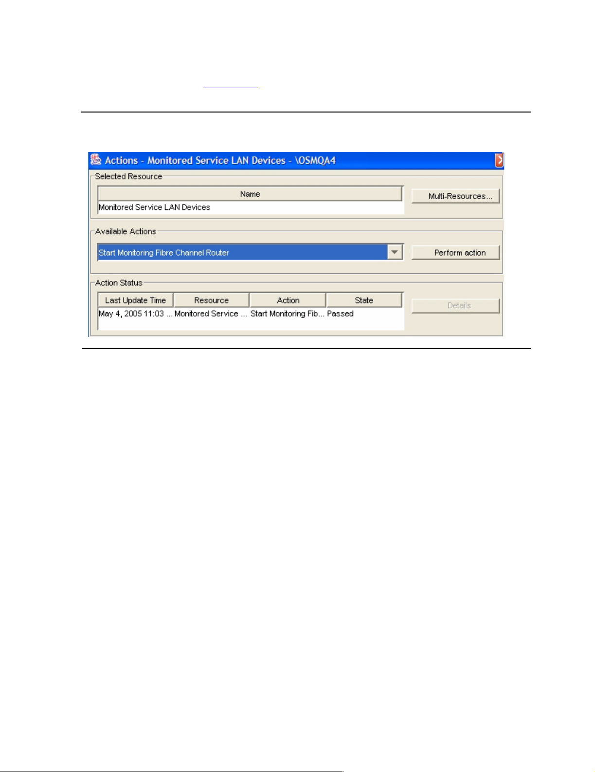
4. Select Start Monitoring Fibre Channel Router and then click on the Perform
action button. See Figure C-2.
Figure C-2. Actions Dialog Box
Configuring the Fiber Channel to SCSI Router for
OSM Monitoring
5. A small window appears and prompts you for:
a. Router’s user name (default user name = “root”)
b. Router’s password (default password = “root”)
c. Router’s IP address (default IP address = “192.231.36.101”)
d. Name (can be any alphanumeric string to logically identify the device)
For more help on attributes and actions of the router on OSM, see OSM Online Help
(F1).
M8201R Fibre Channel to SCSI Router Installation and User’s Guide—529971-005
C-3
Page 54

Configuring OSM for Monitoring the Fibre Channel to
SCSI Router
Configuring the Fiber Channel to SCSI Router for
OSM Monitoring
M8201R Fibre Channel to SCSI Router Installation and User’s Guide—529971-005
C-4
Page 55

Safety and Compliance
Regulatory Compliance Statements
The following regulatory compliance statements apply to the products documented by
this manual.
Consumer Safety Statements
FCC Compliance
This equipment has been tested and found to comply with the limits for a Class A
digital device, pursuant to part 15 of the FCC Rules. These limits are designed to
provide reasonable protection against harmful interference when the equipment is
operated in a commercial environment. This equipment generates, uses, and can
radiate radio frequency energy and, if not installed and used in accordance with the
instruction manual, may cause interference to radio communications. Operation of this
equipment in a residenti al area is likely to cause harm ful interfer ence in wh ich case the
user will be required to correct the interference at his own expense.
Any changes or modifications not expressly approved by Hewlett Packard Company
could avoid the user's authority to operate this equipment.
CISPR Compliance
This equipment complies with the requirements of CISPR 22 (EN 55 022) for Class A
Information Technology Equipment (ITE). In a domestic environment this product may
cause radio interference in which case the user may be required to take adequate
measures.
Canadian Compliance
This class A digital apparatus meets all the requirements of the Canadian InterferenceCausing Equipment Regulations.
Cet appareil numérique d e la classe A r especte toutes le s exigence s du R ègel ment sur
le matériel brouilleur du Canada.
M8201R Fibre Channel to SCSI Router Installation and User’s Guide—529971-005
Statements-1
Page 56
Safety and Compliance
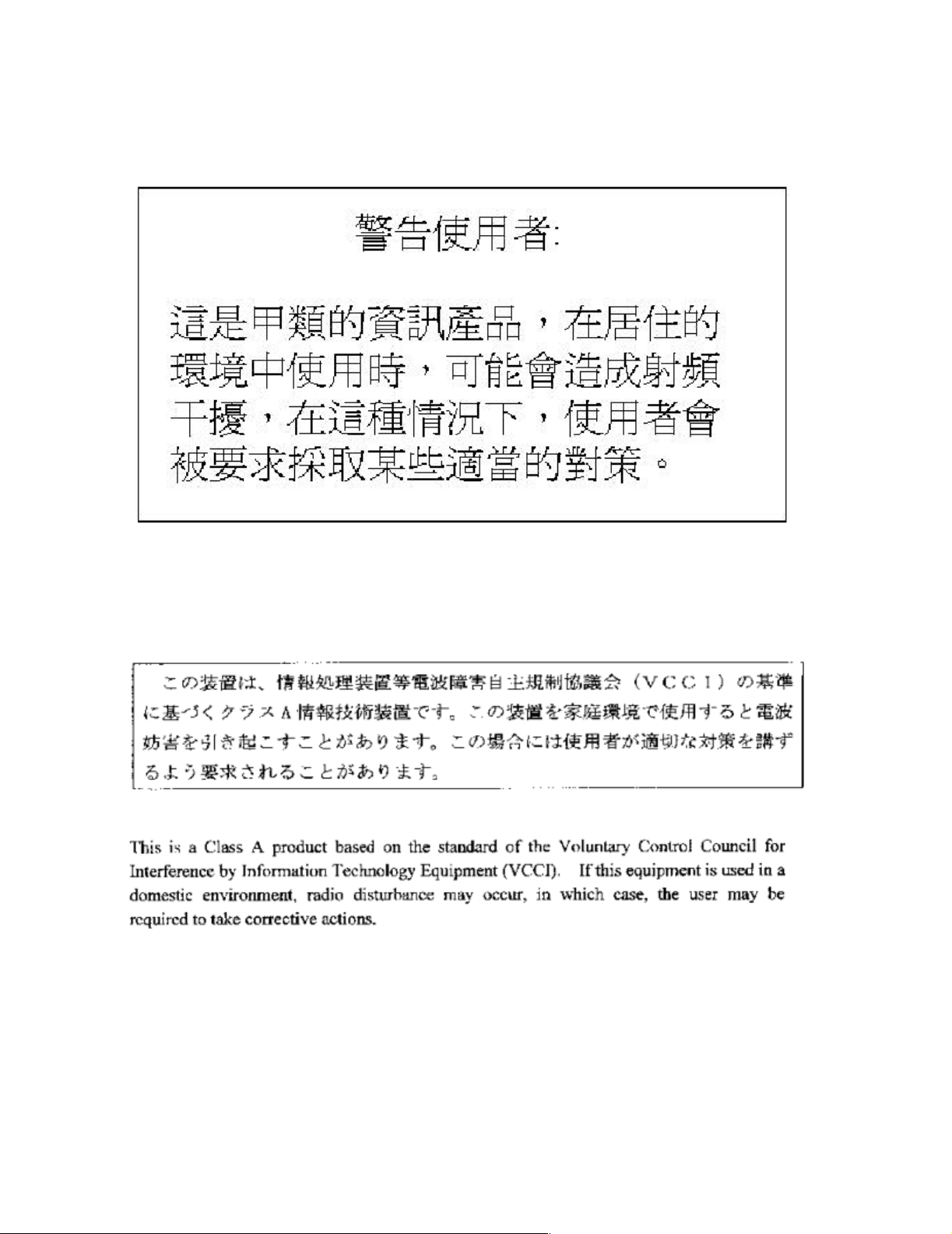
Taiwan (BSMI) Complia nce
Taiwan (BSMI) Compliance
JAPAN (VCCI) Compliance
M8201R Fibre Channel to SCSI Router Installation and User’s Guide—529971-005
Statements-2
Page 57

Safety and Compliance
Supplier Name: Hewlett Packard Company
JAPAN (VCCI) Compliance
Supplier Address Hewlett Packard Company
Nonstop Enterprise Division
10300 North Tantau Avenue
Cupertino, California 95014
Represented in the EU By:
Hewlett Packar d Company
P.O. Box 81 02 44
81902 Munich
Germany
Declares under our sole responsibility that the following product
Product Name: Fibre Channel to SCSI Router
Regulatory Model: N.A.
Product Model: M8201R
Conforms to the following normative European and International Standards
Product Safety: EN 60950:1995 (IEC 950 2nd Edition)
Electromatic
Compatibility
EN 55022:1998 - Radiated & Conducted Emissions
EN 61000 - 3 - 2:1995 - Harmonic Current Emissions
EN 61000 - 3 - 3:1995 - Voltage Fluctuation and Flicker
EN 55024:1998 - EMC Immunity
Following the provisions of the normative European Council Directives:
EMC Directive 89/336/EEC (including amendments)
Low Voltage Directive 73/23/EEC (amended by 93/68/EEC)
Supplementary Information:
Safety: Protection Class I, Pollution Degree II
Emissions: EMC Class A
Year Assessed / First Production: 2002
M8201R Fibre Channel to SCSI Router Installation and User’s Guide—529971-005
Statements-3
Page 58

Safety and Compliance
Chuck Denning
Manager, Hardware Product Assurance
NonStop Enterprise Division
Cupertino, California
JAPAN (VCCI) Compliance
M8201R Fibre Channel to SCSI Router Installation and User’s Guide—529971-005
Statements-4
Page 59

Index
D
Data connections
Fibre Channel port 1-3
SCSI ports 1-3
F
Fibre Channel ServerNet adapter 1-1, 3-6
Fibre Channel to SCSI router
configuration 4-1
LUN mapping table 4-1
SCF command 4-1
Ethernet configuration B-3
hardware configuration 1-2
installation 3-1
fiber cables 3-6
POST 3-7, 6-3
rear view 3-3, 6-2
SCSI cables 3-1
tape drive 3-4, 6-1
mounting 2-2
overview 1-1
serial port connection B-1
specifications A-1
dimensions A-1
rear panel components A-1
troubleshooting 5-1
indicators 5-2
technical support 5-1
visual inspection 5-1
unpacking 2-1
N
NonStop NS-series server 1-1, 3-5, 4-1
S
Supported storage devices 1-3
M8201R Fibre Channel to SCSI Router Installation and User’s Guide—529971-005
Index -1
Page 60

Index
S
M8201R Fibre Channel to SCSI Router Installation and User’s Guide—529971-005
Index -2
 Loading...