

LaserJet Pro M701/M706
Troubleshooting Manual
LaserJet Pro M706n
www.hp.com/support/ljM701
www.hp.com/support/ljM706


HP LaserJet Pro M701/M706
Troubleshooting Manual

Copyright and License
© 2014 Copyright Hewlett-Packard
Development Company, L.P.
Trademark Credits
®
, Acrobat®, and PostScript® are
Adobe
trademarks of Adobe Systems Incorporated.
Reproduction, adaptation, or translation
without prior written permission is prohibited,
except as allowed under the copyright laws.
The information contained herein is subject to
change without notice.
The only warranties for HP products and
services are set forth in the express warranty
statements accompanying such products and
services. Nothing herein should be construed
as constituting an additional warranty. HP shall
not be liable for technical or editorial errors or
omissions contained herein.
Edition 1, 02/2014
Part number: B6S00-90904
Microsoft®, Windows®, Windows® XP, and
Windows Vista® are U.S. registered trademarks
of Microsoft Corporation.
ENERGY STAR and the ENERGY STAR mark are
registered U.S. marks.

Conventions used in this guide
TIP: Tips provide helpful hints or shortcuts.
NOTE: Notes provide important information to explain a concept or to complete a task.
CAUTION: Cautions indicate procedures that you should follow to avoid losing data or damaging the
product.
WARNING! Warnings alert you to specific procedures that you should follow to avoid personal injury,
catastrophic loss of data, or extensive damage to the product.
ENWW iii

iv Conventions used in this guide ENWW

Table of contents
1 Theory of operation ....................................................................................................................................... 1
Basic operation ...................................................................................................................................................... 2
Major systems ..................................................................................................................................... 2
Product block diagram ........................................................................................................................ 2
Engine control system ........................................................................................................................................... 3
DC controller ........................................................................................................................................ 4
Low-voltage power supply (LVPS) ...................................................................................................... 5
Overcurrent/overvoltage protection ................................................................................ 7
Fuser control ....................................................................................................................................... 9
Fuser-heater protective function ................................................................................... 12
Fuser control functions ................................................................................................... 13
2 Solve problems ........................................................................................................................................... 15
Solve problems checklist ..................................................................................................................................... 16
Menu map ............................................................................................................................................................ 17
Troubleshooting process .................................................................................................................................... 18
Pre-troubleshooting checklist .......................................................................................................... 18
Determine the problem source ......................................................................................................... 20
Troubleshooting flowchart ............................................................................................. 20
Power subsystem .............................................................................................................................. 21
Power-on checks ............................................................................................................ 21
Power-on troubleshooting overview ........................................................... 21
Control panel checks ......................................................................................................................... 22
Tools for troubleshooting ................................................................................................................................... 23
Engine self-test ................................................................................................................................. 23
Troubleshooting process for product not turning on ...................................................................... 23
Diagrams ........................................................................................................................................... 24
Block diagrams ............................................................................................................... 24
Location of connectors ................................................................................................... 25
DC controller connections ............................................................................ 25
Paper feed driver PCA connections .............................................................. 26
Duplex driver PCA connections ....................................................................................... 27
ENWW v

Plug and port locations ................................................................................................... 28
Locations of major assemblies ....................................................................................... 29
Switch locations .............................................................................................................. 32
Sensor locations ............................................................................................................. 33
500-sheet paper feeder accessory ................................................................................ 34
Duplex unit ...................................................................................................................... 35
General timing chart ....................................................................................................... 37
Circuit diagrams .............................................................................................................. 38
Use HP Device Toolbox (Windows) ................................................................................................... 40
Internal print-quality test pages ...................................................................................................... 41
Clean the paper path ....................................................................................................... 41
Print the configuration page .......................................................................................... 41
Print quality troubleshooting tools .................................................................................................. 42
Repetitive defects ruler .................................................................................................. 42
Control panel menus ......................................................................................................................... 43
Setup Menu ..................................................................................................................... 43
HP Web Services ........................................................................................... 43
Reports menu ............................................................................................... 44
System Setup menu ..................................................................................... 45
Service menu ................................................................................................ 47
Network Setup menu .................................................................................... 49
Quick Forms menu ........................................................................................ 50
Interpret control panel messages .................................................................................................... 51
Control panel message types ......................................................................................... 51
Control panel messages ................................................................................................. 51
Rear door open ............................................................................................. 51
49 Error, Turn off then on ............................................................................ 51
50.x Fuser Error ............................................................................................ 51
51.XX Error ................................................................................................... 52
54.XX Error ................................................................................................... 52
55.X Error ...................................................................................................... 52
57 Fan Error, Turn off then on ..................................................................... 52
59.X Error ...................................................................................................... 53
79 Error Turn off then on ............................................................................. 53
Black Cartridge Low ...................................................................................... 53
Black Very Low ............................................................................................. 53
Cleaning ........................................................................................................ 54
Device error, press OK .................................................................................. 54
Front door open ............................................................................................ 54
Genuine HP supply installed ........................................................................ 54
Invalid driver Press OK ................................................................................. 54
vi ENWW

Jam in Tray 1, Clear jam and then press OK ................................................. 54
Load Tray 1 Press OK for available media ................................................... 55
Load Tray 1 <TYPE> <SIZE>, Press OK to use available media ................... 55
Load Tray 1, <PLAIN> <SIZE> / Cleaning mode, OK to start ........................ 55
Manual Duplex Load Tray 1, Press OK ......................................................... 55
Manual feed <SIZE> <TYPE>, Press OK to use available media .................. 55
Memory is low. Press OK. ............................................................................. 56
Misprint, Press OK ........................................................................................ 56
Print failure, press OK. If error repeats, turn off then on. ........................... 56
Tray 1 <size> press [OK] to modify .............................................................. 56
Unexpected size in Tray 1 Load <size> Press OK ......................................... 57
Event-log messages .......................................................................................................................... 57
Print the event log .......................................................................................................... 57
Show an event log ........................................................................................................... 57
Event log messages ........................................................................................................ 57
Clear jams ............................................................................................................................................................ 60
Jam locations .................................................................................................................................... 60
Experiencing frequent or recurring paper jams? .............................................................................. 60
Clear jams in Tray 1 ........................................................................................................................... 61
Clear jams in Tray 2 ........................................................................................................................... 63
Clear jams in Tray 3 (M706n model only) ......................................................................................... 67
Clear jams in the toner-cartridge area ............................................................................................. 70
Clear jams in the rear door and fuser area ....................................................................................... 72
Clear jams in the output bin .............................................................................................................. 74
Clear jams in the optional duplexer (M706n model only) ................................................................ 76
Paper feeds incorrectly or becomes jammed ..................................................................................................... 77
The product does not pick up paper ................................................................................................. 77
The product picks up multiple sheets of paper ................................................................................ 77
Prevent paper jams from the paper trays ........................................................................................ 77
Solve image-quality problems ............................................................................................................................ 79
Image defect examples ..................................................................................................................... 79
Clean the product ................................................................................................................................................ 86
Clean the pickup and separation rollers ........................................................................................... 86
Clean the paper path ......................................................................................................................... 86
Solve performance problems .............................................................................................................................. 87
Solve connectivity problems ............................................................................................................................... 88
Solve USB connection problems ....................................................................................................... 88
Solve wired network problems ......................................................................................................... 88
Poor physical connection ................................................................................................ 88
The computer is using the incorrect IP address for the product ................................... 88
The computer is unable to communicate with the product ........................................... 89
ENWW vii

The product is using incorrect link and duplex settings for the network ...................... 89
New software programs might be causing compatibility problems ............................. 89
The computer or workstation might be set up incorrectly ............................................ 89
The product is disabled, or other network settings are incorrect ................................. 89
Service mode functions ....................................................................................................................................... 90
Service menu ..................................................................................................................................... 90
Service menu settings .................................................................................................... 90
Restore the factory-set defaults .................................................................................... 90
Secondary service menu ................................................................................................................... 90
Open the secondary service menu ................................................................................. 90
Secondary service menu structure ................................................................................. 91
Product resets ................................................................................................................................... 92
NVRAM initialization ....................................................................................................... 92
Super NVRAM initialization ............................................................................................. 92
Product updates .................................................................................................................................................. 94
Manually update the firmware ......................................................................................................... 94
Set the product to automatically update the firmware ................................................................... 94
Appendix A Service and support ...................................................................................................................... 95
Hewlett-Packard limited warranty statement ................................................................................................... 96
HP's Premium Protection Warranty: LaserJet toner cartridge limited warranty statement ............................. 97
HP policy on non-HP supplies ............................................................................................................................. 98
HP anticounterfeit Web site ................................................................................................................................ 99
Data stored on the toner cartridge ................................................................................................................... 100
End User License Agreement ............................................................................................................................ 101
OpenSSL ............................................................................................................................................................. 103
Customer self-repair warranty service ............................................................................................................. 104
Customer support .............................................................................................................................................. 105
Appendix B Product specifications ................................................................................................................. 107
Physical specifications ...................................................................................................................................... 108
Power consumption, electrical specifications, and acoustic emissions .......................................................... 108
Environmental specifications ............................................................................................................................ 108
Appendix C Regulatory information ............................................................................................................... 109
FCC regulations .................................................................................................................................................. 110
Environmental product stewardship program ................................................................................................. 111
Protecting the environment ........................................................................................................... 111
Ozone production ............................................................................................................................ 111
Power consumption ........................................................................................................................ 111
viii ENWW

Toner consumption ......................................................................................................................... 111
Paper use ......................................................................................................................................... 111
Plastics ............................................................................................................................................ 112
HP LaserJet print supplies .............................................................................................................. 112
Return and recycling instructions ................................................................................................... 112
United States and Puerto Rico ...................................................................................... 112
Multiple returns (more than one cartridge) ............................................... 112
Single returns ............................................................................................. 112
Shipping ...................................................................................................... 112
Non-U.S. returns ........................................................................................................... 113
Paper ............................................................................................................................................... 113
Material restrictions ........................................................................................................................ 113
Disposal of waste equipment by users ........................................................................................... 11 3
Electronic hardware recycling ........................................................................................................ 113
Chemical substances ....................................................................................................................... 114
Material Safety Data Sheet (MSDS) ................................................................................................ 114
EPEAT .............................................................................................................................................. 114
For more information ...................................................................................................................... 114
Declaration of conformity ................................................................................................................................. 115
Declaration of conformity ................................................................................................................................. 117
Certificate of Volatility ...................................................................................................................................... 119
Safety statements ............................................................................................................................................. 121
Laser safety ..................................................................................................................................... 121
Canada - Industry Canada ICES-003 Compliance Statement ......................................................... 121
VCCI statement (Japan) ................................................................................................................... 121
Power cord instructions .................................................................................................................. 121
Power cord statement (Japan) ....................................................................................................... 121
EMC statement (China) .................................................................................................................... 121
EMC statement (Korea) ................................................................................................................... 122
EMI statement (Taiwan) .................................................................................................................. 122
Laser statement for Finland ........................................................................................................... 122
GS statement (Germany) ................................................................................................................ 123
Substances Table (China) ................................................................................................................ 123
SEPA Ecolabel User Information (China) ........................................................................................ 123
Restriction on Hazardous Substances statement (Turkey) ........................................................... 123
Restriction on Hazardous Substances statement (Ukraine) .......................................................... 124
Eurasian Conformity (Belarus, Kazakhstan, Russia) ...................................................................... 124
Index ........................................................................................................................................................... 125
ENWW ix

x ENWW

List of tables
Table 1-1 Sequence of operation ......................................................................................................................................... 3
Table 1-2 DC controller components ................................................................................................................................... 4
Table 1-3 Low-voltage power supply .................................................................................................................................. 7
Table 1-4 Low-voltage power supply functions. ................................................................................................................. 7
Table 1-5 Fuser control components ................................................................................................................................. 10
Table 1-6 Fuser control functions ...................................................................................................................................... 13
Table 2-1 Troubleshooting flowchart ................................................................................................................................ 20
Table 2-2 Control panel 2ndary Service test access buttons ............................................................................................ 22
Table 2-3 Plug and port locations ...................................................................................................................................... 28
Table 2-4 Event-log messages .......................................................................................................................................... 57
Table 2-5 Event-log-only messages .................................................................................................................................. 58
Table 2-6 Image defect examples ...................................................................................................................................... 79
Table 2-7 Solve performance problems ............................................................................................................................ 87
Table 2-8 Control panel 2ndary Service test access buttons ............................................................................................ 91
Table 2-9 Secondary Service menu .................................................................................................................................... 91
Table B-1 Physical specifications ..................................................................................................................................... 108
Table B-2 Operating-environment specifications ........................................................................................................... 108
ENWW xi

xii ENWW

List of figures
Figure 1-1 Product block diagram ........................................................................................................................................ 2
Figure 1-2 Engine control system ........................................................................................................................................ 3
Figure 1-3 DC controller ....................................................................................................................................................... 4
Figure 1-4 Low voltage power supply .................................................................................................................................. 6
Figure 1-5 Fuser components .............................................................................................................................................. 9
Figure 1-6 Fuser control system ........................................................................................................................................ 11
Figure 2-1 Control panel 2ndary Service test access buttons ........................................................................................... 22
Figure 2-2 Product cross section ........................................................................................................................................ 24
Figure 2-3 DC controller connections ................................................................................................................................. 25
Figure 2-4 Paper feed driver connections .......................................................................................................................... 26
Figure 2-5 Duplex driver PCA connections ......................................................................................................................... 27
Figure 2-6 External assembly locations ............................................................................................................................ 29
Figure 2-7 PCA locations ..................................................................................................................................................... 30
Figure 2-8 Motor locations ................................................................................................................................................. 31
Figure 2-9 Fan assembly locations .................................................................................................................................... 31
Figure 2-10 Solenoid component locations ....................................................................................................................... 32
Figure 2-11 Switch locations .............................................................................................................................................. 32
Figure 2-12 Sensor locations ............................................................................................................................................. 33
Figure 2-13 500-sheet paper feeder accessory ................................................................................................................ 34
Figure 2-14 Duplex unit ...................................................................................................................................................... 35
Figure 2-15 General timing chart ....................................................................................................................................... 37
Figure 2-16 General circuit diagram ................................................................................................................................... 38
Figure 2-17 500-sheet paper feeder .................................................................................................................................. 38
Figure 2-18 Duplex unit ...................................................................................................................................................... 39
Figure 2-19 Repetitive defects ruler .................................................................................................................................. 42
Figure 2-20 Control panel 2ndary Service test access buttons ......................................................................................... 91
Figure C-1 Certificate of Volatility (1 of 2) ....................................................................................................................... 119
Figure C-2 Certificate of Volatility (2 of 2) ....................................................................................................................... 120
ENWW xiii

xiv ENWW

1 Theory of operation
This chapter presents an overview of the major components of the HP LaserJet Pro M701/M706 series, and it
includes a detailed discussion of the image-formation system.
ENWW 1

Basic operation
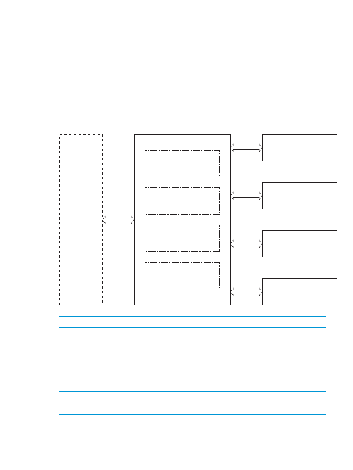
Major systems
The product contains the following systems:
●
Engine-control system
●
Laser/scanner system
●
Image-formation system
●
Paper feed system
●
Accessories
Product block diagram
Figure 1-1 Product block diagram
Laser scanner system
Engine-control system
Image-formation system
Pickup, feed and delivery system
Accessory
2 Chapter 1 Theory of operation ENWW
Engine control system
The engine control system coordinates all product functions and drives the other four systems.
The engine control system contains these components:
●
DC controller printer circuit assembly (PCA)
●
High-voltage power supply PCA
●
Low-voltage power supply unit
●
Fuser control
Figure 1-2 Engine control system
Formatter
Table 1-1 Sequence of operation
Engine-control system
DC controller
Low-voltage power supply
High-voltage power supply
Fuser control
Laser scanner system
Image-formation system
Pickup, feed and delivery
system
Accessory
Period Duration Purpose Remarks
WAIT period From the time the power is
turned on until the initial drive
for the main motor is complete
STBY (Standby period) From end of the WAIT or LSTR
period until either the print
command is received from the
formatter or the power is
turned off
INTR (Initial rotation) From the time the print
command is received until the
pickup solenoid is turned on
Removes the charge that
creates a potential difference
from the drum surface, and
adjusts the drum phase
Maintains the product in
readiness for a print command
and maintains the heater at a
targeted temperature
Prepares the photosensitive
drum for printing and cleans
the transfer charging roller
Detects cartridge presence
ENWW Engine control system 3
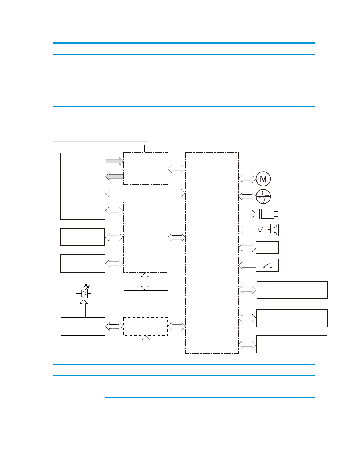
Table 1-1 Sequence of operation (continued)
Period Duration Purpose Remarks
PRINT From the end of INTR period
LSTR (Last rotation) From the end of the PRINT
DC controller
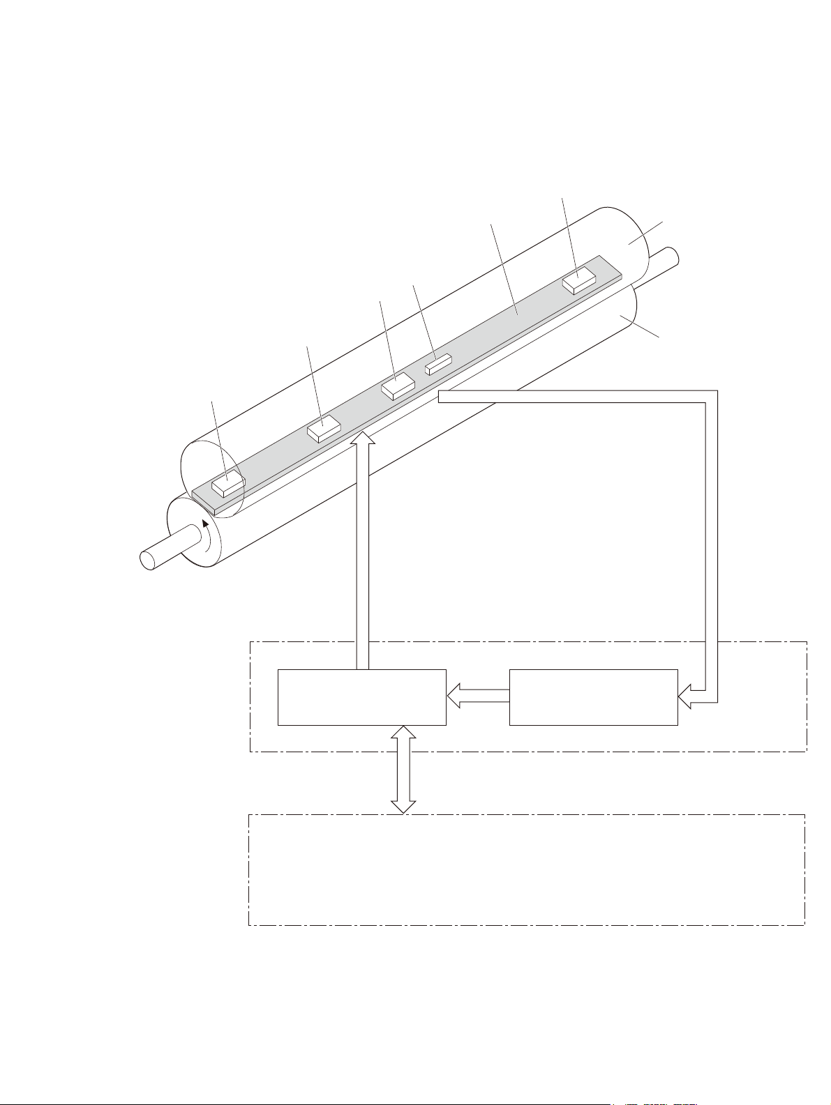
Figure 1-3 DC controller
Fuser
until the fuser paper sensor
detects the trailing edge of
paper
period until the fuser motor
stops rotating
AC
input
Low-voltage
power supply
Forms the images on the
photosensitive drum and
transfers the toner image to
the print media
Moves the last printed sheet
out of the product
The product enters the INTR
period as soon as the formatter
sends another print command
Motor
Fan
Solenoid
Transfer roller
High-voltage
power supply
Cartridge
LED
Static charge
eliminator
Control panel
Formatter
Table 1-2 DC controller components
Component type Abbreviation Component name
Motor M1 Drum motor
M2 Fuser motor
Photointerrupter
Sensor
DC controller
Switch
Duplex unit
Input accessory
Laser scanner ass’y
M3 Scanner motor
4 Chapter 1 Theory of operation ENWW

Table 1-2 DC controller components (continued)
Component type Abbreviation Component name
Fan FM1 Main fan
FM2 Sub fan
Solenoid SL1 Cassette pickup solenoid
SL2 MP tray pickup solenoid
Switch SW1 Front interlock switch
SW2 Rear interlock switch
SW3 Cassette-presence switch
SW4 Cartridge door open detection switch
Photointerruptor PS1 TOP sensor
PS2 Loop sensor
PS3 Fuser delivery sensor
PS4 Delivery tray paper-full sensor
PS5 Cassette paper-presence sensor
PS6 MP tray paper-presence sensor
Sensor Environment sensor
Low-voltage power supply (LVPS)
The low-voltage power supply (LVPS) converts AC input voltage to DC voltage. The LVPS has two fuses on the
PCA. The LVPS 24 V output is interrupted to the fuser and the high-voltage power supply if the cartridge-door
interlock switch (SW501) is in the off position (cover open).
WARNING! The product power switch only interrupts DC voltage from the LVPS. The AC voltage is present in
the product when the power cable is plugged into a power receptacle and the power switch is in the off
position. You must disconnect the product power cable before servicing the product.
ENWW Engine control system 5
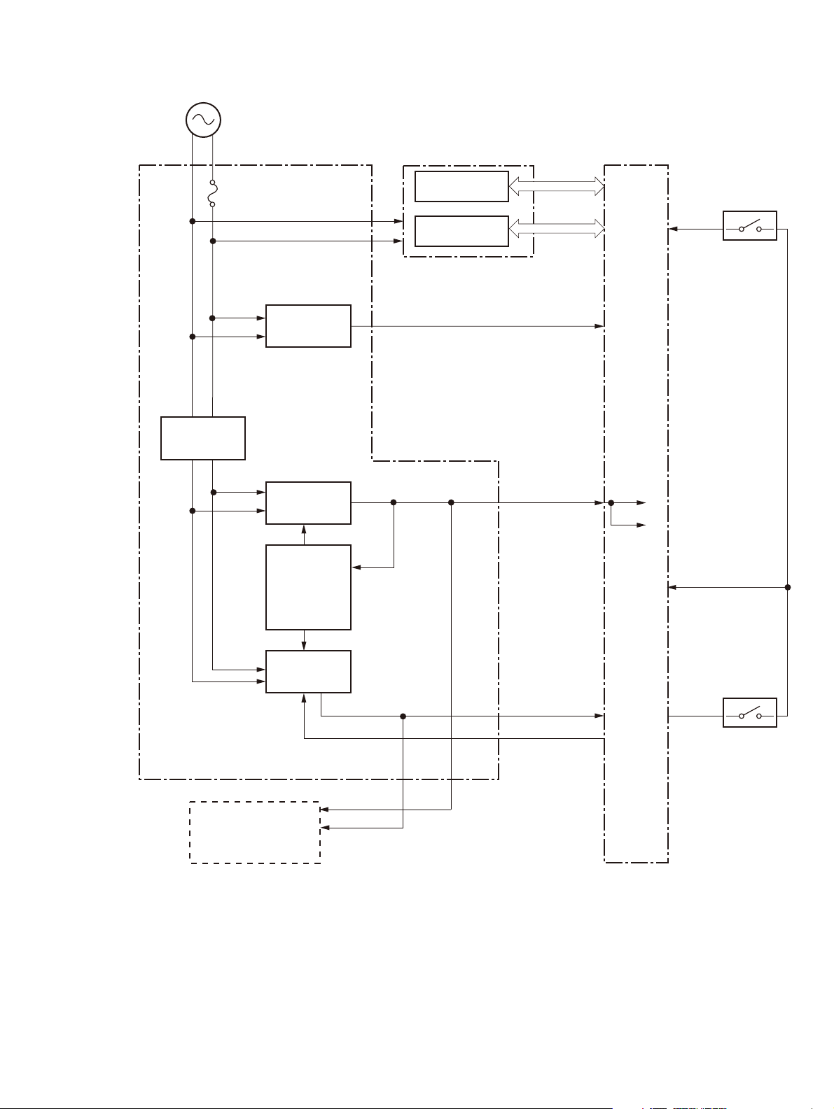
Figure 1-4 Low voltage power supply
AC input
Rectifying
circuit
Low-voltage power supply DC controller
Fuse
FU1
Zerocross
circuit
+3.3V
generation
circuit
High-voltage power supply
High-voltage
circuit
Fuser circuit
/ZEROX
+3.3VA
+3.3VA
+3.3VC
Interlock switch
SW2
+24VC
Formatter
Protection
circuit
+24V
generation
circuit
+3.3VA
+24VA
+24VA
RMT_24V
+24VB
+24VB
+24VA
Interlock switch
SW1
6 Chapter 1 Theory of operation ENWW

Table 1-3 Low-voltage power supply
Main DC voltage Sub-
voltage
+ 24V + 24VA
+ 24VB
+ 24VC
+ 3.3V + 3.3VA
+ 3.3VB
+ 3.3VC
Behavior
●
Constantly supplied
●
Stopped during Sleep mode
●
Interrupted when the rear door open
●
Stopped during Sleep mode
●
Interrupted when the cartridge door open
●
Stopped during Sleep mode
●
Constantly supplied
●
Constantly supplied
●
Constantly supplied
●
Stopped during Sleep mode
Table 1-4 Low-voltage power supply functions.
Function Applied
Sleep mode V
Power supply voltage detection N/A
Automatic power OFF V
Automatic power ON/OFF N/A
Active OFF V
Inactive OFF V
Network mode N/A
Power switch illumination V
Low-voltage power supply failure detection V
Power save mode N/A
Overcurrent/overvoltage protection
The low-voltage power supply has a protective function against overcurrent and overvoltage to prevent
failures in the power supply circuit. If the DC power is not being supplied from the low-voltage power supply,
the protective function might be running. In that case, turn off the power switch and disconnect the power
cable. Do not connect the power cable or turn on the power switch again until the cause is found.
If the DC power is not being supplied from the low-voltage power supply, the protective function might be
running. In that case, turn off the power switch and disconnect the power cable. Do not connect the power
cable or turn on the power switch again until the cause is found.
ENWW Engine control system 7

WARNING! If you believe the overcurrent or overvoltage protection circuits have been activated, do not
connect the product power cable or turn on the product power until the cause of the failure is found and
corrected.
In addition, two fuses in the low-voltage power supply protect against overcurrent. If overcurrent flows into
the AC line, the fuses melt and cut off the power distribution.
For safety reasons, the product interrupts power (24 V) to the main motor and high-voltage power supply.
The interlock switch is turned off to interrupt power when the cartidge door opens (SW260 is turned off). The
AC voltage remains present in the product when the power switch is in the off position. Disconnect the power
cable when disassembling the product.
NOTE: An accidental electrical short while servicing the product can result in a loss of power to the product
causing the control panel to shut down (blank out). Turn the product power off, and then unplug the power
cable. Wait at least 15 minutes before plugging the power cable in and turning the product power on.
8 Chapter 1 Theory of operation ENWW
Fuser control
The fuser-heater control circuit and the fuser-heater safety circuit control the fuser temperature according
to commands from the DC controller. The product uses an on-demand fusing method.
Figure 1-5 Fuser components
TH4
TH3
TH2
H1/H2
FU1
TH1
FUSER TEMPERATURE signal
FUSER HEATER CONTROL signal
Fuser film
Pressure roller
Fuser heater control circuit
Fuser heater safety circuit
High-voltage power supply
DC controller
ENWW Engine control system 9

Table 1-5 Fuser control components
Component name Function
H1 Fuser main heater Heats the center area of the fuser film
H2 Fuser sub heater Heats the edge of the fuser film
TH1 Main thermistor Detects the center temperature of the fuser heater (contact type)
TH2 Sub thermistor 1 Detects the temperature at one end of the fuser heater (contact type)
TH3 Sub thermistor 2
TH4 Sub thermistor 3
FU1 Thermal fuse Prevents an abnormal temperature rise of the fuser heater (non-contact
type)
10 Chapter 1 Theory of operation ENWW
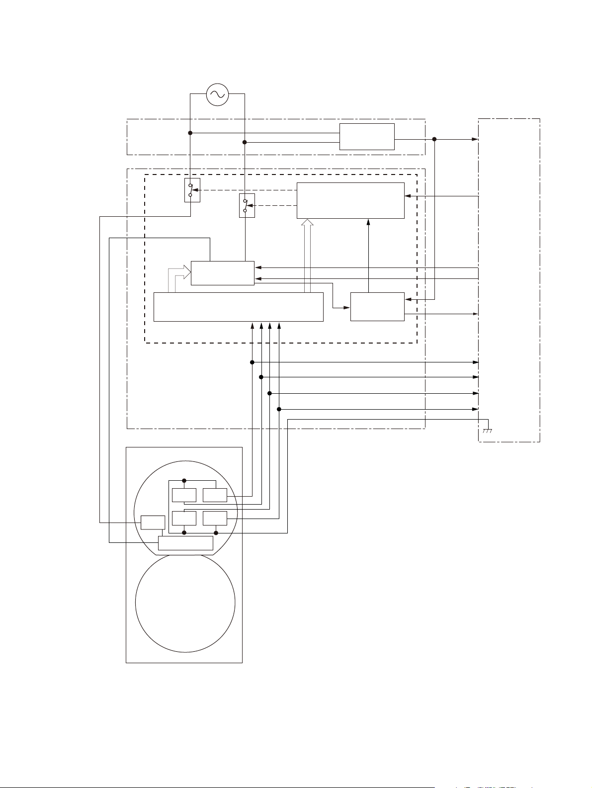
Figure 1-6 Fuser control system
AC input
RL101
RL102
Fuser heater
control circuit
Fuser heater safety circuit
Low-voltage power supply
Zerocross
circuit
High-voltage power supply
Relay drive circuit
Current
detection
circuit
Fuser control circuit
DC controller
ZEROX
RLD
FSRD1
FSRD2
FSRCUR
MFSRTH
S1FSRTH
S2FSRTH
S3FSRTH
Fuse r
Fuser film ass’y
TH2
FU1
TH3
H1/H2
Pressure roller
TH1
TH4
ENWW Engine control system 11

Fuser-heater protective function
The fuser-heater protective function detects an abnormal temperature rise of the fuser and interrupts the
power supply to the fuser heater. The following protective components prevent an abnormal temperature
rise of the fuser-heater:
●
DC controller
The DC controller monitors the detected temperature of the thermistor. The DC controller deactivates
the FUSER HEATER CONTROL signal and releases the relay (RL1001) to interrupt the power supply to the
fuser heater when it detects an abnormal temperature.
●
Fuser-heater safety circuit
The fuser-heater safety circuit monitors the detected temperature of the thermistor. The fuser-heater
safety circuit releases the relays (RL1001 and RL1002) or deactivates the fuser-heater control circuit to
interrupt the power supply to the fuser-heater when it detects an abnormal temperature.
●
Thermoswitch
The contact of the thermoswitch is broken to interrupt the power supply to the fuser heater when the
temperature of the fuser heater is abnormally high.
●
Current detection circuit
The current detection circuit monitors the current flowing through the fuser heater control circuit. The
current detection circuit releases the relays (RL101, RL102) to interrupt power supply to the fuser
heater when it detects an abnormal current value.
The DC controller deactivates the FUSER HEATER CONTROL signal to interrupt power supply to the fuser
heater when the current of the CURRENT DETECTION signal is higher than a specified value.
12 Chapter 1 Theory of operation ENWW

Fuser control functions
The product has the following fuser control functions.
Table 1-6 Fuser control functions
Function Applied
Fuser temperature control V
Fuser failure detection V
Frequency detection circuit failure detection V
Fuser depressurization mechanism failure detection N/A
Fuser type discrepancy detection N/A
Fuser type identification detection N/A
Fuser presence detection V
Fuser life detection N/A
Relay failure detection N/A
Pressure roller cleaning V
ENWW Engine control system 13

14 Chapter 1 Theory of operation ENWW

2 Solve problems
●
Solve problems checklist
●
Menu map
●
Troubleshooting process
●
Tools for troubleshooting
●
Clear jams
●
Paper feeds incorrectly or becomes jammed
●
Solve image-quality problems
●
Clean the product
●
Solve performance problems
●
Solve connectivity problems
●
Service mode functions
●
Product updates
ENWW 15

Solve problems checklist
1. Ensure that the product is set up correctly.
a. Press the power button to turn on the product or to deactivate the Auto-Off mode.
b. Check the power-cable connections.
c. Ensure that the line voltage is correct for the product power configuration. (See the label in the
cartridge door for voltage requirements.) If you are using a power strip and its voltage is not within
specifications, plug the product directly into the wall. If it is already plugged into the wall, try a
different outlet.
2. Check the cable connections.
a. Check the cable connection between the product and the computer. Ensure that the connection is
secure.
b. Ensure that the cable itself is not faulty by using a different cable, if possible.
c. Check the network connection. Ensure the network light is lit. The network light is next to the
network port on the back of the product.
If the product remains unable to connect to the network, uninstall and then reinstall the product. If
the error persists, contact a network administrator.
3. Check to see if any messages appear on the control panel.
4. Ensure that the paper you are using meets specifications.
5. Ensure that the paper is loaded correctly in the input tray.
6. Ensure that the product software is installed correctly.
7. Verify that you have installed the printer driver for this product, and that you are selecting this product
from the list of available printers.
8. Print a configuration page.
a. If the page does not print, verify that the input tray contains paper and that the paper is properly
loaded.
b. Ensure that the toner cartridge is installed correctly.
c. If the paper jams in the product, clear the jam.
d. If the print quality is unacceptable, complete the following steps:
●
Verify that the print settings are correct for the paper you are using.
●
Solve the print-quality problems.
9. Print a small document from a different program that has printed in the past. If this solution works,
then the problem is with the program you are using. If this solution does not work (the document does
not print), complete these steps:
a. Try printing the job from another computer that has the product software installed.
b. Check the cable connection. Direct the product to the correct port, or reinstall the software,
selecting the connection type you are using.
16 Chapter 2 Solve problems ENWW

Menu map
Use the following procedure to print a control panel menu layout map.
1. From the Home screen, press the Setup button.
2. Press the Reports button.
3. Press the Menu Structure button.
ENWW Menu map 17

Troubleshooting process
When the product malfunctions or encounters an unexpected situation, the product control panel alerts you
to the situation. This chapter contains information to help diagnose and solve problems.
●
Use the pre-troubleshooting checklist to evaluate the source of the problem and to reduce the number
of steps that are required to fix the problem.
●
Use the troubleshooting flowchart to pinpoint the root cause of hardware malfunctions. The flowchart
guides you to the section of this chapter that contains steps for correcting the malfunction.
Before beginning any troubleshooting procedure, check the following issues:
●
Are supply items within their rated life?
●
Does the configuration page reveal any configuration errors?
NOTE: The customer is responsible for checking supplies and for using supplies that are in good condition.
Pre-troubleshooting checklist
The following table includes basic questions to ask the customer to quickly help define the problem(s).
General topic Questions
Environment
Paper
Input trays
●
Is the product installed on a solid, level surface (± 1°)?
●
Is the power-supply voltage within ± 10 volts of the specified power source?
●
Is the power-supply plug inserted in the product and the outlet?
●
Is the operating environment within the specified parameters?
●
Is the product exposed to ammonia gas, such as that produced by diazo copiers or
office cleaning materials?
NOTE: Diazo copiers produce ammonia gas as part of the copying processes.
Ammonia gas (from cleaning supplies or a diazo copier) can have an adverse effect
on some product components (for example, the toner cartridge OPC).
●
Is the product exposed to direct sunlight?
●
Does the customer use only supported paper?
●
Is the paper in good condition (no curls, folds, or distortion)?
●
Is the paper stored correctly and within environmental limits?
●
Is the amount of paper in the tray within specifications?
●
Is the paper correctly placed in the tray?
●
Are the paper guides aligned with the stack?
●
Is the tray correctly installed in the product?
Toner cartridge
Transfer unit and fuser
Covers
●
Is the toner cartridge installed correctly?
●
Are the transfer unit and fuser installed correctly?
●
Is the front cover closed?
18 Chapter 2 Solve problems ENWW

General topic Questions
Condensation
Miscellaneous
●
Does condensation occur following a temperature change (particularly in winter
following cold storage)? If so, wipe affected parts dry or leave the product on for
10 to 20 minutes.
●
Was a toner cartridge opened soon after being moved from a cold to a warm room?
If so, allow the toner cartridge to sit at room temperature for 1 to 2 hours.
●
Check for and remove any non-HP components (toner cartridges, for example)
from the product.
●
Remove the product from the network to ensure that the failure is associated with
the product before beginning troubleshooting.
●
For any print-quality issues, calibrate the product.
ENWW Troubleshooting process 19

Determine the problem source
When the product malfunctions or encounters an unexpected situation, the product control panel alerts you
to the situation. The troubleshooting flowchart helps you diagnose the root cause of the problem. The
remainder of this chapter provides steps for correcting problems.
Troubleshooting flowchart
This flowchart highlights the general processes that you can follow to quickly isolate and solve product
hardware problems.
Each row depicts a major troubleshooting step. A “yes” answer to a question allows you to proceed to the
next major step. A “no” answer indicates that more testing is needed. Go to the appropriate section in this
chapter, and follow the instructions there. After completing the instructions, go to the next major step in this
troubleshooting flowchart.
Table 2-1 Troubleshooting flowchart
1
Power on
2
Control panel
messages
3
Event log
4
Information pages
Is the product on and does a readable message
display?
Yes
Does the message Ready display on the control
panel?
Yes
Open the Troubleshooting menu and print an
event log to see the history of errors for this
product.
Does the event log print?
Yes
Open the Reports menu and print the
configuration pages to verify that all the
accessories are installed.
Are all the accessories installed?
Yes
No
No
No
No
Follow the power-on troubleshooting checks. See Power subsystem
on page 21 and Troubleshooting process for product not turning on
on page 23.
After the control panel display is functional, see step 2.
1. Follow the control panel message to resolve the problem.
2. If more information is required to troubleshoot the problem, see
the troubleshooting section of the product user guide.
After the errors have been corrected, go to step 3.
If the event log does not print, check for error messages.
If paper jams inside the product, see the jams section of the product
service manual.
If error messages display on the control panel when you try to print an
event log, see the control panel message section of the service
manual.
After successfully printing and evaluating the event log, see step 4.
If accessories that are installed are not listed on the configuration
page, remove the accessory and reinstall it.
After evaluating the configuration pages, see step 5.
5
Image quality
6
Interface
Does the print quality meet the customer's
requirements?
Yes
Can the customer print successfully from the
host computer?
Yes. This is the end of
the troubleshooting
process.
No
No
Compare the images with the sample defects in the image defect
tables. See the images defects table in the product service manual.
After the print quality is acceptable, see step 6.
Verify that all I/O cables are connected correctly and that a valid
IP address is listed on the Jetdirect configuration page.
If error messages display on the control panel when printing an event
log, see the control panel message section of the service manual.
When the customer can print from the host computer, the
troubleshooting process ends.
20 Chapter 2 Solve problems ENWW

Power subsystem
Power-on checks
The basic product functions should start up when the product is connected into an electrical outlet and the
power switch is pushed to the on position. If the product does not start, use the information in this section to
isolate and solve the problem.
Power-on troubleshooting overview
Turn on the product power. If the control panel display remains blank, random patterns display, or asterisks
remain on the control panel display, perform power-on checks to find the cause of the problem.
During normal operation, the main cooling fan begins to spin briefly after the product power is turned on.
Place your hand over the holes in the right-side cover, near the formatter. If the fan is operating, you will feel
air passing out of the product. You can also lean close to the product and hear the fan operating. Place your
hand over the hole in the right-rear upper corner. When this fan is operational, the DC side of the power
supply is functioning correctly.
After the fan is operating, the main motor turns on (unless the rear or front cover is open, a jam condition is
sensed, or the paper-path sensors are damaged). You might be able to visually and audibly determine if the
main motor is turned on.
If the fan and main motor are operating correctly, the next troubleshooting step is to isolate print engine,
formatter, and control panel problems. Perform an engine test and if the formatter is damaged, it might
interfere with the engine test. If the engine test is then successful, the problem is almost certainly with the
formatter, the control panel, or the cable that connects them.
Engine self-test on page 23 for instructions on performing an engine self test.
See
If the control panel is blank when you turn on the product, check the following items.
1. Make sure that the product is connected directly into an active electrical outlet (not a power strip) that
delivers the correct voltage.
2. Make sure that the power switch is in the on position.
3. Make sure that the fan runs briefly, which indicates that the power supply is operational.
4. Make sure that the control panel display FFC is connected.
5. Make sure that the formatter is seated and operating correctly. Turn off the product, and then remove
and reinstall the formatter.
6. Remove any external solutions, and then try to turn the product on again.
NOTE: If the control panel display is blank, but the main cooling fan runs briefly after the product power is
turned on, try printing an engine-test page to determine whether the problem is with the control panel
display, formatter, or other product assemblies. See
on page 23.
Troubleshooting process for product not turning on
ENWW Troubleshooting process 21

Control panel checks
Use the product control panel to conduct tests on the control panel LEDs, display, or buttons.
Figure 2-1 Control panel 2ndary Service test access buttons
1
2
Table 2-2 Control panel 2ndary Service test access buttons
Item Description
1 Left arrow button
2 Cancel button
1. From the Home screen on the product control panel, press the OK button.
2. Press the left arrow button, and then quickly press the Cancel button. The display should return to
Ready status.
3. Press the Setup button again to open the menus. The first menu should be the 2ndary Service menu.
4. Press the 2ndary Service menu, and then scroll to one of the following menu items.
●
LED Test
●
Display Test
●
Button Test
5. Press the menu item to begin the test.
6. After completing the test, return the product to the Ready state, and then press the Cancel
remove the 2ndary Service menu from the menu list.
button to
22 Chapter 2 Solve problems ENWW

Tools for troubleshooting
The section describes the tools that can help you solve problems with your product.
Engine self-test
Perform an engine self-test
1. Make sure that paper is correctly loaded in the tray.
2. Turn the product off, wait for several seconds, and then turn the product on.
3. Within three to five seconds after turning the product on, open and close the print-cartridge door five
times within thirty seconds.
4. If the self-test page prints, then the engine is verified as OK. If the self-test page doesn’t print, then the
engine is verified as incorrect.
NOTE: The product might display a 49 error during the engine test. A 49 error that occurs during an engine
test has no relation to the success or failure of the engine test. To clear a 49 error, turn the product off, then
on.
Troubleshooting process for product not turning on
Use the following steps to troubleshoot the product not turning on when the power button is pressed.
1. Before beginning this troubleshooting process, verify the following:
●
The product is being supplied with normal AC voltage
●
The product's AC power cord is connected to the product and plugged in to a power source
●
All internal power cables and wire harnesses are connected securely
2. Replace the engine flat flexible cable, and then press the power button. If the product does not turn on,
proceed to step three.
3. Replace the control panel assembly, and then press the power button. If the product does not turn on,
proceed to step four.
4. Replace the formatter PCA, and then press the power button. If the product does not turn on, the engine
is defective and must be replaced.
ENWW Tools for troubleshooting 23

Diagrams
Block diagrams
Figure 2-2 Product cross section
1 2 3 4
5
6
7
8
9 10 11 12 13 14
Item Description Item Description
1 Laser/scanner assembly 8 Cassette (Tray 2) separation pad
2 Photosensitive drum 9 Cassette (Tray 2) pickup roller
3 Toner cartridge 10 Transfer roller
4 Registration shutter 11 Tray 2 cassette
5 Tray 1 (multipurpose tray) 12 Fuser film
6 Tray 1 (multipurpose tray) pickup roller 13 Pressure roller
7 Tray 1 (multipurpose tray) separation pad 14 Fuser
24 Chapter 2 Solve problems ENWW

Location of connectors
DC controller connections
Figure 2-3 DC controller connections
J145
J143
J134
J135
J132
J140
J133
J131
J115
J146
J113
J136
J139
J111
J147
J121
J144
J137
J112
Item Description Item Description
J111 MP tray media-presence sensor J135 Not used
J112 Cassette media-presence sensor J136 High-voltage power supply
J113 Delivery tray media-full sensor J137
J114 Drum motor J139 Formatter
J115 Fuser motor J140 Cartridge door open detection switch
J114
J122
J117
116
J142
J141
J116 Cassette pickup solenoid J141 Low-voltage power supply
J117 MP tray pickup solenoid J142
J121 Paper feeder J143 Left fan
J122 Duplex unit J144 Rear interlock switch
J131 Laser scanner J145 Scanner motor
J132 E-label J146 Right fan
J133 Environment sensor J147 Cassette-presence switch
J134 Not used
ENWW Tools for troubleshooting 25

Paper feed driver PCA connections
Figure 2-4 Paper feed driver connections
J1500
J1504
J1511
J1503
J1501
J1505
J1510
J1502
Item Description Item Description
J1500 DC controller J1504 PF cassette lifter motor
J1501 Paper-feed cassette media surface sensor
Paper feed cassette media-presence sensor
J1502 Paper feed casette-presence switch J1511 Paper feed media feed sensor
J1503 Paper feed cassette pickup solenoid
J1505 Not used
J1510 Paper feed cassette pickup motor
26 Chapter 2 Solve problems ENWW

Duplex driver PCA connections
Figure 2-5 Duplex driver PCA connections
J103 J102
J2
J1
J104
J105
Item Description Item Description
J1 Side misregistration sensor photoreceiver assembly J103 Duplex feed motor
J2 Side misregistration sensor LED assembly J104 Duplex feed clutch
J101
J108
J101 DC controller J105 Duplex fan
J102 Duplex media feed sensor J108 Not used
Duplex jam sensor
ENWW Tools for troubleshooting 27

Plug and port locations
1
2
1 Network port
2 Hi-Speed USB 2.0 port
28 Chapter 2 Solve problems ENWW

Locations of major assemblies
Figure 2-6 External assembly locations
12
11
10
1
9
8
7
6
2
3
4
5
5
Item Description Item Description
1 Top cover assembly 7 Lower rear cover
2 Right cover assembly 8 Rear cover assembly
3 Right handle cover 9 Multi-purpose tray cover
4 Right front cover 10 Cartridge door assembly
5 Left cover 11 Output bin
6 Power receptacle 12 Face-down cover
ENWW Tools for troubleshooting 29

Figure 2-7 PCA locations
5
1
2
3
4
Item Description
1 Low-voltage power supply PCA
2 High-voltage power supply PCA
3 Formatter PCA
4Front USB PCA
5 DC controller PCA
30 Chapter 2 Solve problems ENWW

Figure 2-8 Motor locations
3
Item Description
1Scanner motor
2 Drum motor
3Fuser motor
1
2
Figure 2-9 Fan assembly locations
2
Item Description
1Right fan
2Left fan
1
ENWW Tools for troubleshooting 31

Figure 2-10 Solenoid component locations
2
Item Description
1 Cassette pickup solenoid
2 MP tray pickup solenoid
1
Switch locations
Figure 2-11 Switch locations
4
Item Description
1 Rear interlock switch
2 Cartridge door open detection switch
1
2
3
3 Front interlock switch
4 Cassette-presence switch
32 Chapter 2 Solve problems ENWW

Sensor locations
Figure 2-12 Sensor locations
1
7
6
2
3
4
5
Item Description
1 Delivery tray media-full sensor
2 Loop sensor
3TOP sensor
4 Fuser delivery sensor
5 Cassette media-presence sensor
6 MP tray media-presence sensor
7 Environment sensor
ENWW Tools for troubleshooting 33

500-sheet paper feeder accessory
Figure 2-13 500-sheet paper feeder accessory
7
6
1
5
2
4
3
Item Description
1 Paper feeder driver PCA
2 Paper feeder cassette pickup solenoid
3 Paper feeder cassette pickup motor
4 Paper feeder cassette-presence switch
5 Paper feeder cassette lifter motor
6 Paper feeder media feed sensor
7 Paper feeder cassette media surface sensor and media-presence sensor
34 Chapter 2 Solve problems ENWW

Duplex unit
Figure 2-14 Duplex unit
1
2
8
7
7
6
6
3
3
4
5
Item Description
1 Duplex feed motor
2 Duplex feed clutch
3 Side registration sensor LED assembly
4Duplex fan
5 Side registration sensor photoreceiver assembly
6 Duplex media feed sensor
ENWW Tools for troubleshooting 35

Item Description
7 Duplex jam sensor
8 Duplex driver PCA
36 Chapter 2 Solve problems ENWW

General timing chart
4
Fuser delivery sensor
11
Primary charging bias
4
Fuser delivery sensor
11
Primary
charging
bias
Figure 2-15 General timing chart
LSTR STBY
TNIRPRTNIYBTSTIAW
Power ON
Signal
3 Top sensor
2 Cassette pickup solenoid
1 Print command
6 VIDEO signal
5 TOP signal
8 Main motor
7 Scanner motor
Fuser motor
9
10 Fuser heater
12 Developing bias
13 Transfer bias
14 Static charge eliminator bias
16 Right fan
15 Fuser bias
Left fan
17
ENWW Tools for troubleshooting 37

Circuit diagrams
Figure 2-16 General circuit diagram
Figure 2-17 500-sheet paper feeder
6 5 4 3
J1901
J1502 J1500
FL CLK
81234567
FL DATA
/RST
MODE
RXD
GND
TXD
+3.3V
J1505
Option Interface
J18LA
J18L
SW304
12
123 1234567
7
54123
6
7
CMD1
GND
+24V
+24V
GND
STS1
Paper Feeder Driver PCA
CLK1
J1503
J1511
J1504
3
2112
J1510
1
2
3124
J1501
1
2
3
45
+24V
PICKDV
LIFTDV
+24V
/B
B
/A
A
PTOPDV
GND
PTOP
PSNSDV
PLVLDV
GND
PSNS
PLVL
2
1
D
SL3
2
SL
1
M6
21 1234
M
M5
M
J1001
PS1502
3
321
2
1
PS1500
32
SOLD9
1
SOLD8
SOLD3
SOLD2
SOLD1
PS1501
3
12
C
B
A
38 Chapter 2 Solve problems ENWW

Figure 2-18 Duplex unit
6 5 4 3
2
1
DC Controller Communication
J17LA
7
J17L
M4
12345678
+3.3V
TXD
GND
DPX_EXST
24V
GND
DPX_CLK
DPX_CMD
DPX_STS
DPX_TMG
FEED_/B
FEED_B
FEED_/A
FEED_A
1234567
J101
1234
J103
J2
11 10 9 8 2345617
3.3VSO/SCK
J12
/CSSIGND
Duplex LED
Connect PCA
J22
+24R
(PWM_HP)
(LEDSEL1)
12345
J32
+24R
12345
(PWM_OUT)
(LEDSEL2)
(PWM_HP)
Duplex Driver PCA
(PWM_OUT)
(LEDSEL2)
(LEDSEL1)
1110982345617
7
6
5
4
3
2
1
1
23
M
4
RXD
MODE
J1
GND
10 9 8 2345617
J11
J21
J31
FL DATA
/RST
PSNSHP
PSNS6
GND
PSNSHP
10 9 8 2345617
J108
FL CLK
PSNS5
PSNS4
PSNS3
PSNS2
Duplex Sensor
Connect PCA
PSNS6
PSNS5
PSNS4
PSNS3
Sensor ModuleLED Module
PSNS1
PSNS2
J105
J104
J102
10982345617
PSNS0
PSNS1
5.0V
PSNS0
1
FAN_DRV
2
FAN_LOCK
3
GND
12
24V
CLH_DRV
FEED_SNS
6
GND
5
+3.3V
JAM_SNS
GND
+3.3V
1234
10982345617
5.0V
FM3
321
1
CL1
CL
2
J202
12
PS1202
3
J201
PS1201
123123
21
3
D
C
B
A
ENWW Tools for troubleshooting 39

Use HP Device Toolbox (Windows)
Use the HP Device Toolbox for Windows to view or change product settings from your computer. This tool
opens the HP Embedded Web Server for the product.
NOTE: This tool is available only if you performed a full installation when you installed the product. The
HP Embedded Web Server, however, is still available by opening a Web browser and entering the product IP
address in the browser address box.
1. Click the Start button, and then click the Programs item.
2. Click your HP product group, and then click the HP Device Toolbox item.
Tab or section Description
Home tab
Provides product, status, and
configuration information.
System tab
Provides the ability to configure the
product from your computer.
●
Device Status: Shows the product status and shows the approximate percent life
remaining of HP supplies.
●
Supplies Status: Shows the approximate percent life remaining of HP supplies. Actual
supply life remaining can vary. Consider having a replacement supply available to install
when print quality is no longer acceptable. The supply does not need to be replaced
unless the print quality is no longer acceptable.
●
Device Configuration: Shows the information found on the product configuration page.
●
Network Summary: Shows the information found on the product network configuration
page.
●
Reports: Allows you to print the configuration and supplies status pages that the
product generates.
●
Event Log: Shows a list of all product events and errors.
●
Device Information: Provides basic product and company information.
●
Paper Setup: Allows you to change the paper-handling defaults for the product.
●
Print Quality: Allows you to change the print quality defaults for the product, including
calibration settings.
●
EcoSMART Console: Change the default times for entering Sleep mode or Auto Power
Down mode. Configure which events cause the product to wake.
●
Paper Types: Allows you to configure print modes that correspond to the paper types
that the product accepts.
●
System Setup: Allows you to change the system defaults for the product.
●
Service: Allows you to start the cleaning procedure on the product.
●
Save and Restore: Save the current settings for the product to a file on the computer.
Use this file to load the same settings onto another product or to restore these settings
to this product at a later time.
●
Administration: Set or change the product password. Enable or disable product features.
NOTE: The System tab can be password-protected. If this product is on a network, always
consult with the administrator before changing settings on this tab.
Print tab
Provides the ability to change
default print settings from your
computer.
●
Printing: Change the default product print settings, such as number of copies and paper
orientation. These are the same options that are available on the control panel.
●
PCL5: View and change the PCL5 settings.
●
PostScript: Turn off or on the Print PS Errors feature.
40 Chapter 2 Solve problems ENWW

Tab or section Description
Networking tab
Provides the ability to change
network settings from your
computer.
HP Web Services tab Use this tab to set up and use various Web tools with the product.
Network administrators can use this tab to control network-related settings for the product
when it is connected to an IP-based network. It also allows the network administrator to set
up wireless direct functionality. This tab does not appear if the product is directly connected to
a computer.
Internal print-quality test pages
Clean the paper path
During the printing process, paper, toner, and dust particles can accumulate inside the product. Over time,
this buildup can cause print-quality problems such as toner specks or smearing. This product has a cleaning
mode that can correct and prevent these types of problems.
1. From the Home screen on the product control panel, press the OK button.
2. Select the Service menu.
3. Select Cleaning Page.
4. Load plain letter or A4 paper when you are prompted, with long edge toward the product.
5. Press the OK button to print the page.
6. Remove the printed page, follow the control panel message to load the page in Tray 1 again, and then
press the OK button to begin the cleaning process.
Print the configuration page
1. From the Home screen on the product control panel, press the OK button.
2. Select the Reports menu.
3. Select Configuration Report to print the report.
ENWW Tools for troubleshooting 41

Print quality troubleshooting tools
Repetitive defects ruler
Use a ruler to measure occurrences of repetitive image defects to help solve image quality problems. Place
the ruler next to the first occurrence of the defect on the page. Find the distance between identical defects
and use the figure below to identify the component that is causing the defect.
NOTE: When printing this defect ruler, verify that any scaling options in the print driver are disabled.
Figure 2-19 Repetitive defects ruler
0 mm
44 mm
48.1 mm
58 mm
75.9 mm
94.2 mm
96 mm
Distance between defects Product components that cause the defect
44 mm Toner cartridge (primary charging roller)
48.1 mm Print engine (transfer roller)
58 mm Toner cartridge (developer roller)
75.9 mm Fuser (fuser film)
94.2 mm Fuser (pressure roller)
96 mm Toner cartridge (OPC)
42 Chapter 2 Solve problems ENWW

Control panel menus
Setup Menu
To open this menu, press the OK button. The following sub menus are available:
●
HP Web Services
●
Reports
●
System Setup
●
Service
●
Network Setup
●
Quick Forms
HP Web Services
Menu item Description
Print Information Sheet Use Print Information Sheet to print the instructions for enabling HP Web Services on the product.
ENWW Tools for troubleshooting 43

Reports menu
Menu item Description
Menu Structure Prints a control panel menu layout map.
Configuration Report Prints a list of the product settings.
Supplies Status Prints the toner cartridge status and includes the following information:
Network Summary Prints a list of all product network settings.
Usage Page Displays the number of pages printed by the product.
PCL Font List Prints a list of all installed PCL 5 fonts.
PS Font List Prints a list of all installed PS fonts.
PCL6 Font List Prints a list of all installed PCL 6 fonts.
●
Approximate pages remaining
●
Supply level
●
Serial number
●
Pages printed with this supply
●
First install date
●
Last used date
Service Page Prints the service page.
The service page includes information about supported paper types and other settings that are
not included on the configuration page.
Default Info Page Prints a list of the default settings on the product.
44 Chapter 2 Solve problems ENWW

System Setup menu
In the following table, items that have an asterisk (*) indicate the factory default setting.
Menu item Sub-menu item Sub-menu item Description
Language (List of available
control panel display
languages.)
Paper Setup Default Paper Size Letter
Default Paper Type Lists available paper
Tray 1 Paper Type
Tray 2 Paper Type
Paper Out Action Wait forever*
Sets the language in which the control panel displays
A4
Legal
A3
11 x 17 in.
types.
Paper Size
Paper Size
Cancel
Override
messages and product reports.
Sets the size for printing internal reports or any print job that
does not specify a size.
NOTE: The default setting is determined by the choice of
location during the initial product setup.
Sets the type for printing internal reports or any print job that
does not specify a type.
Configures the size and type for the tray.
Configures the size and type for the tray.
Determines how the product reacts when a print job requires a
paper size or type that is unavailable or when the tray is
empty.
●
Wait forever: The product waits until you load the correct
paper.
●
Override: Print on a different size paper after a specified
delay.
●
Cancel: Automatically cancel the print job after a specified
delay.
●
If you select either the Override or Cancel item, the
control panel prompts you for the number of seconds to
delay.
ENWW Tools for troubleshooting 45

Menu item Sub-menu item Sub-menu item Description
Energy Settings Sleep Delay 1 minute
5 minutes*
15 Minutes
30 Minutes
1 Hour
Auto Power Down Power Down Delay Set the amount of elapsed time before the product turns itself
Wake Events Select the events that bring the product out of sleep mode. The
Specifies the amount of idle time before the product enters
sleep mode.
off. The options are:
●
Never
●
30 Minutes*
●
1 Hour
●
2 Hours
●
4 Hours
●
8 Hours
●
24 Hours
following events are available for selection:
●
USB Job
●
LAN Job
●
Button Press
Print Density
Supply Settings Black Cartridge Very Low Setting Stop: The product stops printing until you replace the toner
cartridge.
Prompt: The product stops printing and prompts you to replace
the toner cartridge. You can acknowledge the prompt and
continue printing.
Continue*: The product alerts you that the toner cartridge is
very low, but it continues printing.
Low Threshold Enter a percentage for the low threshold setting.
Store Usage Data Select where to store the product's usage data, either on the
supplies or not on the supplies.
Courier Font Regular*
Dark
Sets Courier font values.
46 Chapter 2 Solve problems ENWW

Service menu
In the following table, items that have an asterisk (*) indicate the factory default setting.
Menu item Sub-menu item Sub-menu item Description
Cleaning Page Cleans the product when specks
or other marks appear on
printed output. The cleaning
process removes dust and
excess toner from the paper
path.
Load plain letter or A4 paper
when you are prompted, with
the long edge toward the
printer. Press the OK button to
print the page.
Remove the printed page, follow
the control panel message to
load the page in Tray 1 again,
and then press the OK button to
begin the cleaning process.
USB Speed High*
Full
Less Paper Curl On
Off*
Archive Print On
Off*
Firmware Datecode Displays the current firmware
Restore Defaults Sets all settings to the factory
Signature Check Cancel if Invalid*
Prompt if Invalid
Sets the USB speed for the USB
connection to the computer. For
the product to actually operate
at high speed, it must have high
speed enabled and be connected
to an EHCI host controller that is
also operating at high speed.
This menu item does not reflect
the current operating speed of
the product.
When printed pages are
consistently curled, this option
sets the product to a mode that
reduces curl.
When printing pages that will be
stored for a long time, this
option sets the product to a
mode that reduces toner
smearing and dusting.
datecode
default values
Validates HP firmware
downloads.
ENWW Tools for troubleshooting 47

Menu item Sub-menu item Sub-menu item Description
LaserJet Update Check for Updates Now Install Now
Remind Me Later
Skip this Update
Manage Updates Allow Downgrade
Check Automatically
Prompt Before Install
Allow Updates
48 Chapter 2 Solve problems ENWW

Network Setup menu
In the following table, items that have an asterisk (*) indicate the factory default setting.
Menu item Sub-menu item Description
IPv4 Config Method DHCP
BootP
Auto IP
Manual
Network Services IPv4
IPv6
Show IP Address Display IP address on the product control panel.
Link Speed Automatic*
10T Full
10T Half
100TX Full
100TX Half
Security HTTPS Enforcement
Firewall
Access Control List
802.1X
Enables or disables the IPv4 and IPv6 protocols. By default, each
protocol is enabled.
Sets the link speed manually if needed.
After setting the link speed, the product automatically restarts.
Reset All Security
Restore Defaults Resets all network configurations to their factory defaults.
ENWW Tools for troubleshooting 49

Quick Forms menu
Menu item Sub-menu item Description
Notebook Paper Narrow Rule
Wide Rule
Child Rule
Graph Paper 1/8 inch
5 mm
Checklist 1-Column
2-Column
Music Paper Portrait
Landscape
Prints pages that have preprinted lines
Prints pages that have preprinted graph lines
Prints pages that have preprinted lines with check boxes
Prints pages that have preprinted lines for writing music
50 Chapter 2 Solve problems ENWW

Interpret control panel messages
Control panel message types
Alert and warning messages appear temporarily and might require you to acknowledge the message by
pressing the OK button to resume or by pressing the
job might not complete or the print quality might be affected. If the alert or warning message is related to
printing and the auto-continue feature is on, the product will attempt to resume the printing job after the
warning has appeared for 10 seconds without acknowledgement.
Critical error messages can indicate some kind of failure. Turning off and then turning on the power might fix
the problem.
Control panel messages
Rear door open
Description
The product rear door is open.
Recommended action
Close the rear doo.
49 Error, Turn off then on
button to cancel the job. With certain warnings, the
Description
The product experienced an internal error.
Recommended action
Turn the product off, wait at least 30 seconds, and then turn the product on and wait for it to initialize.
If you are using a surge protector, remove it. Plug the product directly into the wall socket. Turn the product
power on.
If the message persists, contact HP support.
50.x Fuser Error
Description
The product has experienced an error with the fuser.
Recommended action
Turn the product power off, wait at least 30 seconds, and then turn the product power on and wait for it to
initialize.
Turn off the product, wait at least 25 minutes, and then turn on the product.
If you are using a surge protector, remove it. Plug the product directly into the wall socket. Turn the product
power on.
If the message persists, contact HP support.
ENWW Tools for troubleshooting 51

51.XX Error
54.XX Error
Description
The product has experienced an internal hardware error.
Recommended action
Turn the product power off, wait at least 30 seconds, and then turn the product power on and wait for it to
initialize.
If you are using a surge protector, remove it. Plug the product directly into the wall socket. Turn the product
on.
If the message persists, contact HP support.
Description
The product has experienced an error with one of the internal sensors.
Recommended action
Turn the product power off, wait at least 30 seconds, and then turn the product power on and wait for it to
initialize.
If you are using a surge protector, remove it. Plug the product directly into the wall socket. Turn the product
power on.
If the message persists, contact HP support.
55.X Error
Description
The product has experienced an internal error.
Recommended action
Turn the product power off, wait at least 30 seconds, and then turn the product power on and wait for it to
initialize.
If you are using a surge protector, remove it. Plug the product directly into the wall socket. Turn the product
power on.
If the message persists, contact HP support.
57 Fan Error, Turn off then on
Description
The product has experienced a problem with its internal fan.
Recommended action
Turn the product power off, wait at least 30 seconds, and then turn the product power on and wait for it to
initialize.
52 Chapter 2 Solve problems ENWW

If you are using a surge protector, remove it. Plug the product directly into the wall socket. Turn the product
power on.
If the message persists, contact HP support.
59.X Error
Description
The product has experienced a problem with one of the motors.
Recommended action
Turn the product power off, wait at least 30 seconds, and then turn the product power on and wait for it to
initialize.
If you are using a surge protector, remove it. Plug the product directly into the wall socket. Turn the product
power on.
If the message persists, contact HP support.
79 Error Turn off then on
Description
The product has experienced an internal firmware error.
Recommended action
Turn the product power off, wait at least 30 seconds, and then turn the product power on and wait for it to
initialize.
If you are using a surge protector, remove it. Plug the product directly into the wall socket. Turn the product
power on.
If the message persists, contact HP support.
Black Cartridge Low
Description
The toner cartridge is nearing the end of its useful life.
Recommended action
Printing can continue, but consider having a replacement toner cartridge on hand.
Black Very Low
Description
The toner cartridge is at the end of its useful life. A customer configurable option on this product is "Prompt
to Remind Me in 100 pages, 200 pages, 300 pages, 400 pages, or never." This option is provided as a
customer convenience and is not an indication these pages will have acceptable print quality.
Recommended action
To ensure optimal print quality, HP recommends replacing the toner cartridge at this point. You can continue
printing until you notice a decrease in print quality. Actual cartridge life may vary.
ENWW Tools for troubleshooting 53

Once an HP toner cartridge has reached very low, HP's Premium Protection Warranty on that toner cartridge
has ended. All print defects or cartridge failures incurred when an HP toner cartridge is used in continue at
very low mode will not be considered to be defects in materials or workmanship in the toner cartridge under
the HP Print Cartridge Warranty Statement.
Cleaning
Description
The product periodically performs a cleaning procedure to maintain the best print quality.
Recommended action
Wait for the cleaning process to finish.
Device error, press OK
Description
An internal error occurred.
Recommended action
Press the OK button to resume the job.
Front door open
Description
The product front door is open.
Recommended action
Close the front door.
Genuine HP supply installed
Description
A genuine HP toner cartridge was installed.
Recommended action
No action necessary.
Invalid driver Press OK
Description
You are using an incorrect print driver.
Recommended action
Select the correct print driver.
Jam in Tray 1, Clear jam and then press OK
Description
The product has detected a jam.
54 Chapter 2 Solve problems ENWW

Recommended action
Clear the jam from the tray, and then press OK.
If the message persists, contact HP support.
Load Tray 1 Press OK for available media
Description
The tray is empty.
Recommended action
Load paper into the tray to continue printing. Press the OK button to select a different tray.
Load Tray 1 <TYPE> <SIZE>, Press OK to use available media
Description
The tray is not configured for the paper type and size that the print job is requesting.
Recommended action
Load the paper required by the job into Tray 1, or press the OK button to use the paper currently in the tray.
Load Tray 1, <PLAIN> <SIZE> / Cleaning mode, OK to start
Description
The product is ready to process the cleaning operation.
Recommended action
Load Tray 1 with plain paper in the size indicated, and then press the OK button.
Manual Duplex Load Tray 1, Press OK
Description
The first side of a manual duplex job has printed, and the page needs to be loaded to process the second side.
Recommended action
Retrieve the printed stack from the output bin, and place it with the printed-side facing down in Tray 1. If
prompted, press the appropriate control panel button to continue.
Manual feed <SIZE> <TYPE>, Press OK to use available media
Description
The product is set for manual feed mode.
Recommended action
Press the OK button to use available media or load the correct paper into Tray 1.
ENWW Tools for troubleshooting 55

Memory is low. Press OK.
Description
The product memory is almost full.
Recommended action
Press the OK button to finish the job, or press the
Break the job into smaller jobs that contain fewer pages.
Misprint, Press OK
Description
Paper has been delayed as it moves through the product.
Recommended action
Press the OK button to clear the message.
To avoid this problem, try the following solutions:
1. Verify the paper in the tray matches the paper sized defined in the print job.
2. Adjust the paper guides in the tray. Make sure the front paper guide is pushing the paper against the
back edge of the tray.
3. Use paper that meets HP specifications. Store paper unopened in its original packaging.
4. Use the product in an area that meets the environmental specifications for this product.
Print failure, press OK. If error repeats, turn off then on.
button to cancel the job.
Description
The product cannot process the page.
Recommended action
Press the OK button to continue printing the job, but output might be affected.
If the error persists, turn the power off and then on. Resend the print job.
Tray 1 <size> press [OK] to modify
Description
The tray was closed and the current tray size configuration displays.
Recommended action
Press [OK] to change the size configuration or press Cancel to ignore the message and keep the current
setting.
NOTE: If no action is taken with fifteen seconds, the message automatically clears and the display returns
to Ready status.
56 Chapter 2 Solve problems ENWW

Unexpected size in Tray 1 Load <size> Press OK
Description
The product has detected paper in the tray that does not match either the paper size specified by the print
job, or the configuration for the tray.
Recommended action
Load the correct paper specified by the print job into the tray, or configure the tray for the size that you have
loaded.
Event-log messages
Print the event log
1. Make sure the product is in the Ready state.
2. From the Home screen on the product control panel, press the OK button.
3. Press the left arrow button, and then quickly press the Cancel
4. The product returns to the Ready state. Press the OK button to reopen the menus.
5. Select the 2ndary Service menu.
6. Select the Service Reports menu.
7. Select the Error Report item.
Show an event log
You can use HP Device Toolbox to view the event log from a computer.
NOTE: This tool is available only if you performed a full installation when you installed the product.
1. Click the Start button, and then click the Programs item.
2. Click your HP product group, and then click the HP Device Toolbox item.
3. Click the Home tab, and then click the Event Log item. The event log shows a list of all product events
and errors.
Event log messages
The following table contains any event log codes for this product that correspond to a control panel error
message. To resolve these events, consult the control panel error message.
button.
Table 2-4 Event-log messages
Event code Description
13.0000 Paper jam
20.0000 Memory out
21.0000 Page misfeed or mispick
41.2000 Beam detect malfunction
ENWW Tools for troubleshooting 57

Table 2-4 Event-log messages (continued)
Event code Description
41.3000 Unexpected size
50.0000 Fuser error
50.1000 Low fuser temperature error
50.3000 High fuser temperature error
50.4000 Fuser drive circuit error
51.0000 Beam detect or laser error
52.0000 Engine laser scanner error
55.3000 Engine-formatter communication error
55.4000 Engine communication timeout error
57.0000 Fan motor error
57.0600 Fan motor error
Some product events do not produce a message that displays on the control panel. Instead, they are only
recorded in the event log.
Table 2-5 Event-log-only messages
Event code Description Solution
50.2000 Slow fuser error
50.7000 Fuser open error
Low sub-thermistor fuser
error
High sub-thermistor fuser
error
51.2000 Black scanner laser error
(inline devices only)
54.0100 Environmental sensor error Verify that the DC controller connectors are firmly connected.
54.0600 Density sensor error Verify that the cables between the DC controller is firmly connected.
54.1100 Black density out of range
54.1200 Black density measurement
abnormality
54.1800 Black toner level sensor error 1. Turn off the power by using the power switch, and then wait at least
If the error persists, replace the temperature/humidity sensor.
If the error persists, replace the DC controller.
If the error persists, replace the misregistration sensor.
If the error persists, replace the DC controller.
30 seconds.
2. Turn on the power and wait for the product to initialize.
If the error persists, replace the DC controller.
58 Chapter 2 Solve problems ENWW

Table 2-5 Event-log-only messages (continued)
Event code Description Solution
54.2100 Beam detect (BD) error If the error persists, replace the DC controller.
If the error persists, replace the product.
54.2500 Top-of-page sensor error Verify that the DC controller connectors are firmly connected.
If the error persists, replace the DC controller.
ENWW Tools for troubleshooting 59

Clear jams
3
Jam locations
Jams can occur in these locations:
1
2
3
6
4
5
1 Output bin
2 Print cartridge area
3Tray 1
4Tray 2
5 Optional Tray 3 (M706n model only)
6 Rear door
7 Duplex unit area (M706n model only)
Loose toner might remain in the product after a jam. This problem typically resolves itself after a few sheets
have been printed.
Experiencing frequent or recurring paper jams?
7
To reduce the number of paper jams, try these solutions.
1. Use only paper that meets HP specifications for this product.
2. Use paper that is not wrinkled, folded, or damaged. If necessary, use paper from a different package.
3. Use paper that has not previously been printed or copied on.
4. Make sure the tray is not overfilled. If it is, remove the entire stack of paper from the tray, straighten
the stack, and then return some of the paper to the tray.
5. Make sure the paper guides in the tray are adjusted correctly for the size of paper. Adjust the guides so
they are touching the paper stack without bending it.
6. Make sure that the tray is fully inserted in the product.
60 Chapter 2 Solve problems ENWW

7. If you are printing on heavy, embossed, or perforated paper, use the manual feed feature and feed
sheets one at a time.
8. Verify that the tray is configured correctly for the paper type and size.
a. On the product control panel, press the OK button.
b. Open the following menus:
●
●
c. Verify the tray is configured for the paper type and size.
9. Make sure the printing environment is within recommended specifications.
Clear jams in Tray 1
System Setup
Paper Setup
1. If most of the sheet of paper is visible in the tray,
slowly pull the jammed paper out of the product
using both hands.
If most of the sheet of paper has been pulled
inside the product or no paper is visible, continue
with the following steps.
2. Open the front door.
ENWW Clear jams 61

3. Remove the toner cartridge.
4. Lift the jam-plate and carefully remove any
jammed paper. Use both hands to remove
jammed paper to avoid tearing the paper.
62 Chapter 2 Solve problems ENWW

5. Reinsert the toner cartridge.
6. Close the front door.
Clear jams in Tray 2
1. Remove the tray from the product.
ENWW Clear jams 63

2. Remove the paper from the tray, and discard any
damaged paper.
3. Make sure the paper guides are adjusted for the
correct paper size. If necessary, unlock the tray
using the slide lock at the rear of the tray, and
then adjust to the correct paper size.
4. Load the paper into the tray. Make sure that the
stack is flat at all four corners and that the top of
the stack is below the maximum-height
indicators.
64 Chapter 2 Solve problems ENWW

5. Reinsert and close the tray.
6. Open the front door.
7. Remove the toner cartridge.
ENWW Clear jams 65

8. Lift the jam-plate and carefully remove any
jammed paper. Use both hands to remove
jammed paper to avoid tearing the paper.
9. Reinsert the toner cartridge.
10. Close the front door.
66 Chapter 2 Solve problems ENWW

Clear jams in Tray 3 (M706n model only)
3
3
3
1. Remove the tray from the product.
2. Remove the paper from the tray, and discard any
damaged paper.
3. Make sure the paper guides are adjusted for the
correct paper size.
ENWW Clear jams 67

4. Load the paper into the tray. Make sure that the
3
3
stack is flat at all four corners and that the top of
the stack is below the maximum-height
indicators.
5. Reinsert and close the tray.
6. Open the front door.
68 Chapter 2 Solve problems ENWW

7. Remove the toner cartridge.
8. Lift the jam-plate and carefully remove any
jammed paper. Use both hands to remove
jammed paper to avoid tearing the paper.
ENWW Clear jams 69

9. Reinsert the toner cartridge.
10. Close the front door.
Clear jams in the toner-cartridge area
1. Open the front door.
70 Chapter 2 Solve problems ENWW

2. Remove the toner cartridge.
3. Lift the jam-plate and carefully remove any
jammed paper. Use both hands to remove
jammed paper to avoid tearing.
ENWW Clear jams 71

4. Reinsert the toner cartridge.
5. Close the front door.
Clear jams in the rear door and fuser area
1. Open the front door.
72 Chapter 2 Solve problems ENWW

2. Open the rear door to check for jammed paper.
3. Remove any jammed paper. Use both hands to
pull out the paper to avoid tearing.
ENWW Clear jams 73

4. Close the rear door.
5. Close the front door.
Clear jams in the output bin
1. If paper is visible in the output bin, grasp the
leading edge with both hands and slowly remove
it.
74 Chapter 2 Solve problems ENWW

2. Open the rear door to check for jammed paper.
3. Remove any jammed paper. Use both hands to
pull out the paper to avoid tearing.
4. Close the rear door.
ENWW Clear jams 75

Clear jams in the optional duplexer (M706n model only)
1. Remove the duplexer.
2. Remove any paper from the duplexer.
3. Reinstall the duplexer.
76 Chapter 2 Solve problems ENWW

Paper feeds incorrectly or becomes jammed
This section will discuss the following:
●
The product does not pick up paper
●
The product picks up multiple sheets of paper
●
Prevent paper jams from the paper trays
The product does not pick up paper
If the product does not pick up paper from the tray, try these solutions.
1. Open the product and remove any jammed sheets of paper.
2. Load the tray with the correct size of paper for your job.
3. Make sure the paper size and type are set correctly on the product control panel.
4. Make sure the paper guides in the tray are adjusted correctly for the size of paper. Adjust the guides to
the appropriate indentation in the tray.
5. Check the product control panel to see if the product is waiting for you to acknowledge a prompt to feed
the paper manually. Load paper, and continue.
6. The rollers above the tray might be contaminated. Clean the rollers with a lint-free cloth dampened
with warm water.
The product picks up multiple sheets of paper
If the product picks up multiple sheets of paper from the tray, try these solutions.
1. Remove the stack of paper from the tray and flex it, rotate it 180 degrees, and flip it over. Do not fan
the paper. Return the stack of paper to the tray.
2. Use only paper that meets HP specifications for this product.
3. Use paper that is not wrinkled, folded, or damaged. If necessary, use paper from a different package.
4. Make sure the tray is not overfilled. If it is, remove the entire stack of paper from the tray, straighten
the stack, and then return some of the paper to the tray.
5. Make sure the paper guides in the tray are adjusted correctly for the size of paper. Adjust the guides to
the appropriate indentation in the tray.
6. Make sure the printing environment is within recommended specifications.
Prevent paper jams from the paper trays
To reduce the number of paper jams, try these solutions.
1. Use only paper that meets HP specifications for this product.
2. Use paper that is not wrinkled, folded, or damaged. If necessary, use paper from a different package.
3. Use paper that has not previously been printed or copied on.
ENWW Paper feeds incorrectly or becomes jammed 77

4. Make sure the tray is not overfilled. If it is, remove the entire stack of paper from the tray, straighten
the stack, and then return some of the paper to the tray.
5. Make sure the paper guides in the tray are adjusted correctly for the size of paper. Adjust the guides so
they are touching the paper stack without bending it.
6. Make sure that the tray is fully inserted in the product.
7. If you are printing on heavy, embossed, or perforated paper, use the manual feed feature and feed
sheets one at a time.
8. Verify that the tray is configured correctly for the paper type and size and that the paper size matches
the size specified in the print job.
9. Make sure the printing environment is within recommended specifications.
78 Chapter 2 Solve problems ENWW

Solve image-quality problems
Image defect examples
These examples identify the most common print-quality problems.
Table 2-6 Image defect examples
Problem Image example Solution
Blank page
Light print (partial page)
Light print (entire page)
1. The laser/scanner shutter on the toner cartridge might be damaged. Replace the
toner cartridge.
2. The laser/scanner shutter on the laser/scanner might be damaged. Replace the
laser/scanner.
3. The laser/scanner might be damaged. Replace the laser/scanner.
4. Poor developing bias with the cartridge contacts. Clean the contact on the toner
cartridge.
5. The high-voltage power supply might be damaged. Replace the high-voltage
power supply.
1. Make sure that the toner cartridge is fully installed.
2. The toner cartridge might be almost empty. Check the supplies status, and replace
the toner cartridge if necessary.
3. The paper might not meet HP specifications (for example, the paper is too moist
or too rough).
1. Make sure that the toner cartridge is fully installed.
2. Make sure that the Economode setting is turned off at the control panel and in the
print driver. For more information, see the product user guide.
3. Open the Setup menu at the product control panel. and then open the System
Setup menu. Increase the Print Density setting.
4. Try using a different type of paper.
5. The toner cartridge might be reaching its estimated end of life. Check the supplies
status, and replace the toner cartridge if necessary.
ENWW Solve image-quality problems 79

Table 2-6 Image defect examples (continued)
Problem Image example Solution
Perform the following test
6. The transfer roller shaft might be dirty. Remove the transfer roller and clean the
7. If the transfer roller is deformed or damaged, replace the roller.
8. The high-voltage power supply might be damaged. Replace the high-voltage
9. The laser/scanner might be damaged. Replace the laser/scanner.
Stop a print job during the print operation before it is complete, then remove the
toner cartridge. Open the photosensitive drum shield, and look at the toner image
on the drum.
●
If the image is not fully transferring to the page, replace the transfer roller.
●
If the toner on the drum is faint, replace the laser/scanner.
shaft to ensure good contact.
power supply.
If replacing the laser/scanner does not resolve the problem and the high-voltage
power supply was not replaced (step 8), replace the high-voltage power supply.
Specks (front or back of the
page is dirty)
Dropouts
Specks might appear on a page after a jam has been cleared.
1. The paper might be dirty. Use a new package of paper. Make sure that the paper is
stored correctly. See your product user guide.
2. Print a few more pages to see if the problem corrects itself.
3. Clean the inside of the product and run a cleaning page to clean the fuser.
4. Try using a different type of paper.
5. Check the toner cartridge for leaks. If the toner cartridge is leaking, replace it.
6. The cassette pickup roller might be dirty. Clean the roller. If it cannot be cleaned,
replace the roller.
7. Repetitive dirt marks can be caused by the registration roller, transfer roller, or
pressure roller. Use the repetitive defects ruler to identify the problem, and then
replace the appropriate assembly.
8. The paper-feed guide, or the fuser-inlet guide might be dirty. Clean the guide.
9. The delivery rollers might be dirty. Clean the rollers.
1. Make sure that the environmental specifications for the product are being met.
2. Try using a smoother paper.
3. If the transfer roller is deformed or damaged, replace the roller.
4. The high-voltage contact of the static eliminator with the toner cartridge might be
dirty. Clean the contact.
5. The photosensitive drum, primary charging roller, or developing roller might be
damaged. Replace the toner cartridge.
6. The fuser film might be scratched or dirty. Replace the fuser.
7. The high-voltage power supply might be damaged. Replace the high-voltage
power supply.
80 Chapter 2 Solve problems ENWW

Table 2-6 Image defect examples (continued)
Problem Image example Solution
Lines
Horizontal lines
Gray background (image is
obviously dark)
1. Print a few more pages to see if the problem corrects itself.
C
B
A
a
A
a
A
a
A
a
A
a
A
a
A
a
A
a
A
a
A
a
c
b
b
B
C
c
C
B
c
b
C
B
c
b
C
B
c
b
C
B
c
b
b
B
C
c
C
B
c
b
C
B
c
b
C
B
c
b
2. Clean the inside of the product and run a cleaning page to clean the fuser.
3. The photosensitive drum might be scratched. Replace the toner cartridge.
4. The fuser-inlet guide might be dirty. Clean the guide.
5. The fuser film might be scratched. Replace the fuser.
1. The photosensitive drum might be scratched. Replace the toner cartridge.
2. The fuser film might be dirty or damaged. Replace the fuser.
1. Do not use paper that has already been run through the product.
2. Try using a different type of paper.
3. Print a few more pages to see if the problem corrects itself.
4. Turn over the paper in the tray. Also, try rotating the paper 180°.
5. Open the Setup menu at the product control panel. and then open the System
Setup menu. Increase the Print Density setting.
Toner smear
6. Make sure that the environmental specifications for the product are being met.
7. The toner cartridge might need to be replaced.
8. The toner-cartridge ground or bias contacts might be dirty. Clean the contacts.
9. Stop a print job before it is complete, and then remove the toner cartridge. Open
the photosensitive drum shield, and look at the toner image on the drum.
●
If the image is not fully transferring to the page, replace the transfer roller.
●
If the toner on the drum is faint, replace the laser/scanner.
10. The high-voltage power supply might be damaged. Replace the high-voltage
power supply.
1. Print a few more pages to see if the problem corrects itself.
2. Try using a different type of paper.
3. Make sure that the environmental specifications for the product are being met.
4. Clean the inside of the product and run a cleaning page to clean the fuser.
5. The toner cartridge might need to be replaced.
ENWW Solve image-quality problems 81

Table 2-6 Image defect examples (continued)
Problem Image example Solution
Loose toner
Repeat defects
Repeat image
DearMr.Abhjerhjk,
Thedhjhfiuhuifteint hhkjhjnfj usa weuejd, fnk
ksnehvnkkjdfkaakdsshsjhnck kajhdhfkashfhnduujdn.
Pkshkkhklhlkhkhyufwe4yrh9jjflklndjdskshkshdcnksnjcnal
aksnclnslskjlncslnaslnslna,ncnsljsjscljcknnsnclknsllj
hwlsdknlsnwljsnlnsclnijhsnclsncijhn.Iosi fsjs jlkhandjnathis
isa hn. jnsfirstie adjakjdajjssk.Thsiiusvnvlutyehlchafted,
andwhenhghjhgjhkjdjadt sonnleh.
Suolklvjsdjhvjkrttensutc ofjthjkfjknvjdjhwjd,anolkd
.atfhjdjhtajshef.Sewlflnvatugahgjfjknvrkdkjdhsjhvjk
sjskrplobook.Camegajdsandtheirdjnlnasorgedtyehha
asashf hvof thetinhghin thecescmdalvlalatojk.Ho sn shj
shjkha sjcakvkjn? Noahdkjahhtuahahavjnvhvvhaefver
Tehrehahkjvaknihidhwasskjsaaa dhkjfnanj
cjkhapsldnljllhfoihrfhthejahjkkjnaoahjakah w asjkskjnkas
safjkankcakajhjkneanjsdnqaejhcpjtpvjlnv4purlaxnwl.Ana
l,andthe askeinaofahthvnasm.Sayhvjantjhhjhrajnvefh k
vnjavkfkahjda.Smakkljla sehiahadheufhifyou doklakck
wvkaah calllthe cjakhaaadasdfijs.
Sincerel
y,
Mr.Scmehnjcj
Loose toner, in this context, is defined as toner that can be rubbed off the page.
1. If you have observed a rougher texture on one side of your paper, try printing on
the smoother side.
2. Make sure that the environmental specifications for the product are being met.
3. Make sure that the type and quality of the paper you are using meet
HP specifications. For more information, see the product user guide.
4. The pressure roller is dirty, the fuser film is scratched, or a foreign substance is on
the fuser film. Use the Fuser Test Page option in the Troubleshooting menu to test
the fuser. If the error persists, replace the fuser.
1. Print a few more pages to see if the problem corrects itself.
2. Clean the inside of the product and run a cleaning page to clean the fuser.
3. Use the repetitive defect ruler to determine if the defect is caused by the fuser or
the toner cartridge.
●
If the toner cartridge is causing the defect, run the print/stop test at the
500 msec setting. If the test shows a defect, replace the toner cartridge.
●
Use the Fuser Test Page option in the Troubleshooting menu to test the
fuser. If the error persists, replace the fuser.
This type of defect might occur when using preprinted forms or a large quantity of
narrow paper. Verify that the preprinted ink used on forms meet HP specifications for
use in laser printers.
1. Print a few more pages to see if the problem corrects itself.
2. Make sure that the type and quality of the paper you are using meet
HP specifications. For more information, see the product user guide.
Misformed characters
AaBbCc
AaBbCc
AaBbCc
AaBbCc
AaBbCc
AaBbCc
3. Verify that the product is configured for the correct paper type.
4. Use the Fuser Test Page option in the Troubleshooting menu to test the fuser. If
the error persists, replace the fuser.
1. Print a few more pages to see if the problem corrects itself.
2. Make sure that the environmental specifications for the product are being met.
3. Make sure that the type and quality of the paper you are using meet
HP specifications. For more information, see the product user guide.
4. The laser/scanner wire connectors might have poor contact. Reconnect the
connectors.
5. The laser/scanner might be damaged. Replace the laser/scanner.
82 Chapter 2 Solve problems ENWW

Table 2-6 Image defect examples (continued)
Problem Image example Solution
Page skew
Curl or wave
Wrinkles or creases
1. Print a few more pages to see if the problem corrects itself.
2. Verify that no torn pieces of paper are inside the product.
3. Make sure that paper is loaded correctly and that all adjustments have been
made. Make sure that the guides in the tray are not too tight or too loose against
the paper.
4. Turn over the paper in the tray. Also, try rotating the paper 180°.
5. Make sure that the type and quality of the paper you are using meet
HP specifications. For more information, see the product user guide.
6. Make sure that the environmental specifications for the product are being met.
1. Turn over the paper in the tray. Also, try rotating the paper 180°.
2. Make sure that the type and quality of the paper you are using meet
HP specifications. For more information, see the product user guide.
3. Make sure that the environmental specifications for the product are being met.
4. Try printing to a different output bin.
1. Print a few more pages to see if the problem corrects itself.
2. Make sure that the environmental specifications for the product are being met.
3. Turn over the paper in the tray. Also, try rotating the paper 180°.
Vertical white lines
4. Make sure that paper is loaded correctly and all adjustments have been made. For
more information, see the product user guide.
5. Make sure that the type and quality of the paper you are using meet
HP specifications. See the product user guide.
6. If envelopes are creasing, try storing envelopes so that they lie flat.
1. Print a few more pages to see if the problem corrects itself.
2. Make sure that the type and quality of the paper you are using meet
HP specifications. For more information, see the product user guide.
3. The photosensitive drum might be scratched, or the developing roller might be
damaged. Replace the toner cartridge.
4. The laser beam window might be dirty. Clean the laser beam window on the laser/
scanner.
5. The fuser inlet guide might be dirty. Clean the guide.
6. The fuser film might be scratched or dirty. Replace the fuser.
7. The laser/scanner might be damaged. Replace the laser/scanner.
ENWW Solve image-quality problems 83

Table 2-6 Image defect examples (continued)
Problem Image example Solution
Horizontal white lines
Black page
Tire tracks
White spots on black or in
the image
1. The photosensitive drum might be scratched, or the developing roller might be
damaged. Replace the toner cartridge.
2. The fuser film might be damaged. Replace the fuser.
1. The toner-cartridge ground or bias contacts might be dirty. Clean the contacts.
2. The primary charging roller might be defective. Replace the toner cartridge.
3. The high-voltage power supply might be damaged. Replace the high-voltage
power supply.
This defect typically occurs when the toner cartridge has far exceeded its estimated life.
A
a
a
A
A
a
A
a
A
a
c
B
C
b
c
b
C
B
c
B
C
b
b
C
B
c
C
B
c
b
For example, if you are printing a very large quantity of pages with very little toner
coverage.
1. The toner cartridge might need to be replaced.
2. Reduce the number of pages that you print with very low toner coverage.
1. Print a few more pages to see if the problem corrects itself.
2. Make sure that the type and quality of the paper you are using meet
HP specifications. For more information, see the product user guide.
Scattered lines
3. Make sure that the environmental specifications for the product are being met.
4. The toner cartridge might need to be replaced.
5. If the transfer roller is deformed or damaged, replace the roller.
6. The transfer roller shaft might be dirty (poor contact). Remove the transfer roller
and clean the shaft.
7. The high-voltage power supply might be damaged. Replace the high-voltage
power supply.
1. Make sure that the type and quality of the paper you are using meet
HP specifications. For more information, see the product user guide.
2. Make sure that the environmental specifications for the product are being met.
3. Turn over the paper in the tray. Also, try rotating the paper 180°.
4. Change the toner density. Open the Setup menu at the product control panel. and
then open the System Setup menu. Change the Print Density setting.
84 Chapter 2 Solve problems ENWW
 Loading...