

Page 1
Service manual: Repair
HP Color LaserJet Enterprise M652, M653
HP Color LaserJet Managed E65050, E65060
HP Color LaserJet Managed E65150, E65160
HP Color LaserJet Enterprise MFP M681, M682
HP Color LaserJet Managed MFP E67550, E67560
HP Color LaserJet Managed MFP E67650, E67660
www.hp.com/videos/LaserJet
www.hp.com/support/colorlj652
www.hp.com/support/colorlj653
www.hp.com/support/ljE65050
www.hp.com/support/ljE65060
www.hp.com/support/colorljE65150
www.hp.com/support/colorljE65160
www.hp.com/support/colorljM681MFP
www.hp.com/support/colorljM682MFP
www.hp.com/support/ljE67550MFP
www.hp.com/support/ljE67560MFP
www.hp.com/support/colorljE67650MFP
www.hp.com/support/colorljE67660MFP
Page 2

Page 3

HP Color LaserJet Enterprise M652, M653
HP Color LaserJet Managed E65050, E65060
HP Color LaserJet Managed E65150, E65160
HP Color LaserJet Enterprise MFP M681, M682
HP Color LaserJet Managed MFP E67550, E67560
HP Color LaserJet Managed MFP E67650, E67660
Service manual: Repair
Page 4

Copyright and License
© Copyright 2019 HP Development Company,
L.P.
Reproduction, adaptation, or translation without
prior written permission is prohibited, except as
allowed under the copyright laws.
The information contained herein is subject to
change without notice.
The only warranties for HP products and
services are set forth in the express warranty
statements accompanying such products and
services. Nothing herein should be construed as
constituting an additional warranty. HP shall not
be liable for technical or editorial errors or
omissions contained herein.
Edition 5, 10/2019
Page 5

Conventions used in this guide
TIP: Helpful hints or shortcuts.
NOTE: Information that explains a concept or how to complete a task.
Reinstallation tip: Reinstallation helpful hints, shortcuts, or considerations.
IMPORTANT: Information that help the user to avoid potential printer error conditions.
CAUTION: Procedures that the user must follow to avoid losing data or damaging the printer.
WARNING! Procedures that the user must follow to avoid personal injury, catastrophic loss of data, or extensive
damage to the printer.
ENWW iii
Page 6

iv Conventions used in this guide ENWW
Page 7

HP service and support
Learn about HP access to additional service and support information.
Additional service and support for channel partners
Channel partners, go to partner.hp.com, and then use the steps below to access the HP Web-based Interactive
Search Engine (WISE).
Access WISE for Channel partners
1. Select
2. Select
Find information about the following topics
● Service manuals
● Service advisories
● Up-to-date control panel message (CPMD) troubleshooting
● Install and
● Printer specification
● Solutions for printer issues and emerging issues
● Remove and replace part instructions and videos
● Warranty and regulatory information
Additional service and support for HP internal personnel
HP internal personnel, go to one of the following Web-based Interactive Search Engine (WISE) sites:
Americas (AMS)
Services & Support, and then select Services Delivery.
Technical Support, and then select Technical Documentation.
configur
– https://support.hp.com/wise/home/ams-enWISE - English
– https://support.hp.com/wise/home/ams-esWISE - Spanish
– https://support.hp.com/wise/home/ams-ptWISE - Portuguese
– https://support.hp.com/wise/home/ams-frWISE - French
Asia Pacifi / Japan (APJ)
○ https://support.hp.com/wise/home/apj-enWISE - English
○ https://support.hp.com/wise/home/apj-jaWISE - Japanese
○ https://support.hp.com/wise/home/apj-koWISE - Korean
○ https://support.hp.com/wise/home/apj-zh-HansWISE - Chinese (simplified
ENWW v
Page 8

○ https://support.hp.com/wise/home/apj-zh-HantWISE - Chinese (traditional)
○ https://support.hp.com/wise/home/apj-thWISE - Thai
Europe / Middle East / Africa (EMEA)
– https://support.hp.com/wise/home/emea-enWISE - English
vi HP service and support ENWW
Page 9

Table of contents
1 Removal and replacement ...................................................................................................................................................................... 1
HP service and support ........................................................................................................................................................... 2
Additional service and support for channel partners .................................................................................... 2
Additional service and support for HP internal personnel ............................................................................ 2
Removal and replacement strategy ...................................................................................................................................... 3
Introduction .......................................................................................................................................................... 3
Considerations during removal and replacement .......................................................................................... 3
Electrostatic discharge ........................................................................................................................................ 4
Required tools ...................................................................................................................................................... 4
Fasteners used in this printer ............................................................................................................................ 5
Service approach ...................................................................................................................................................................... 6
Before performing service .................................................................................................................................. 6
After performing service ..................................................................................................................................... 6
Post service tests ................................................................................................................................................. 6
Print quality test .............................................................................................................................. 6
Copy-quality test (M681/M682/E67550/E67560/E67650/E67660 models) ...................... 6
Fax-quality test (M681/M682/E67550/E67560/E67650/E67660 models) ........................ 7
Parts removal orientation .................................................................................................................................. 7
Removal and replacement procedures ................................................................................................................................. 8
Customer self-repair (CSR) A parts and assemblies ...................................................................................... 8
Install accessory: 1x550-sheet paper feeder ............................................................................. 9
Introduction ................................................................................................................. 9
Step 1: Unpack the accessory ................................................................................... 9
Step 2: Install the 1x550-sheet paper feeder ..................................................... 10
Install accessory: 1x550-sheet paper feeder with stand ...................................................... 14
Introduction ............................................................................................................... 14
Step 1: Unpack the accessory ................................................................................ 14
Step 2: Install the 1x550-sheet paper feeder with stand ................................. 15
Install accessory: 3x550-sheet paper feeder with stand ...................................................... 19
Introduction ............................................................................................................... 19
Step 1: Unpack the accessory ................................................................................ 19
Step 2: Install the 3x550-sheet paper feeder with stand ................................. 20
ENWW vii
Page 10

Install accessory: 2,550-sheet paper feeder with stand ........................................................ 26
Introduction ............................................................................................................... 26
Step 1: Unpack the accessory ................................................................................ 26
Step 2: Install the 2,550-sheet paper feeder with stand .................................. 27
Install accessory: Jetdirect USB wireless print server ............................................................. 35
Introduction ............................................................................................................... 35
Step 1: Unpack the accessory ................................................................................ 35
Step 2: Install the Jetdirect USB wireless print server ....................................... 35
Install accessory: Jetdirect USB wireless print server with NFC ............................................ 42
Introduction ............................................................................................................... 42
Step 1: Unpack the accessory ................................................................................ 42
Step 2: Install the Jetdirect USB wireless print server with NFC ....................... 43
Install accessory: Trusted platform module (TPM) ................................................................. 48
Introduction ............................................................................................................... 48
Step 1: Remove the formatter cover .................................................................... 49
Step 2: Remove the TPM ......................................................................................... 49
Step 3: Unpack the accessory ................................................................................ 50
Step 4: Install the TPM ............................................................................................. 50
Step 5: Install the formatter cover ........................................................................ 51
Install accessory: Internal USB ports ......................................................................................... 53
Introduction ............................................................................................................... 53
Step 1: Remove the formatter cover .................................................................... 54
Step 2: Unpack the accessory ................................................................................ 54
Step 3: Install the internal USB ports .................................................................... 54
Step 4: Install the formatter cover ........................................................................ 57
Install accessory: Foreign interface harness (FIH) ................................................................... 58
Introduction ............................................................................................................... 58
Step 1: Unpack the accessory ................................................................................ 58
Step 2: Install the foreign interface harness (FIH) .............................................. 58
Removal and replacement: Staple cartridge and carrier (Flow M681z/Flow M682z/
Flow E67660z) .............................................................................................................................. 60
Introduction ............................................................................................................... 60
Step 1: Remove the staple cartridge and carrier ................................................ 60
Step 2: Unpack the replacement assembly ......................................................... 62
Step 3: Install the staple cartridge ........................................................................ 62
Removal and replacement: embedded MultiMedia Card (eMMC) ......................................... 64
Introduction ............................................................................................................... 64
Step 1: Remove the formatter cover .................................................................... 65
Step 2: Remove the embedded MultiMedia Card (eMMC) .................................. 65
Step 3: Unpack the replacement assembly ......................................................... 66
Step 4: Install the eMMC .......................................................................................... 66
viii ENWW
Page 11

Step 5: Install the formatter cover ........................................................................ 67
Step 6: Reinstall the printer firmwar ................................................................... 68
Removal and replacement: Hard disk drive (HDD) .................................................................. 69
Introduction ............................................................................................................... 69
Step 1: Remove the formatter cover .................................................................... 70
Step 2: Remove the hard disk drive (HDD; M653dh/M681/M682/
E67550/E67560/E67650/E67660) ...................................................................... 70
Step 3: Unpack the replacement assembly ......................................................... 71
Step 4: Install the HDD ............................................................................................ 71
Step 5: Install the formatter cover ........................................................................ 73
Step 6: Reinstall the printer firmwar ................................................................... 73
Removal and replacement: Dual in-line memory module (DIMM) ....................................... 75
Introduction ............................................................................................................... 75
Step 1: Remove the formatter cover .................................................................... 76
Step 2: Remove the hard disk drive (HDD; M653dh/M681/M682/
E67550/E67560/E67650/E67660) ...................................................................... 76
Step 3: Remove the dual in-line memory module (DIMM) ................................ 77
Step 4: Unpack the replacement assembly ......................................................... 79
Step 5: Install the DIMM ........................................................................................... 79
Step 6: Install the HDD ............................................................................................ 80
Step 7: Install the formatter cover ........................................................................ 82
Removal and replacement: Fax PCA (M681f/Flow M681f/Flow M681z/Flow M682z) ...... 83
Introduction ............................................................................................................... 83
Step 1: Remove the formatter cover .................................................................... 84
Step 2: Remove the fax PCA ................................................................................... 84
Step 3: Unpack the replacement assembly ......................................................... 85
Step 4: Install the fax PCA ....................................................................................... 86
Step 5: Install the formatter cover ........................................................................ 86
Removal and replacement: Document feeder rollers ............................................................ 87
Introduction ............................................................................................................... 87
Step 1: Remove the document feeder rollers ..................................................... 87
Step 2: Unpack the replacement assembly ......................................................... 90
Step 3: Install the document feeder rollers ......................................................... 91
Removal and replacement: Document feeder separation roller cover ................................ 95
Introduction ............................................................................................................... 95
Step 1: Remove the document feeder separation roller cover ........................ 95
Step 2: Unpack the replacement assembly ......................................................... 97
Step 3: Install the document feeder separation roller cover ............................ 97
Removal and replacement: Secondary transfer roller ......................................................... 100
Introduction ............................................................................................................ 100
Step 1: Remove the secondary transfer roller .................................................. 100
ENWW ix
Page 12

Step 2: Unpack the replacement assembly ....................................................... 102
Step 3: Install the secondary transfer roller ...................................................... 102
Removal and replacement: Intermediate transfer belt (ITB) .............................................. 105
Introduction ............................................................................................................ 105
Step 1: Remove the intermediate transfer belt (ITB) ....................................... 105
Step 2: Unpack the replacement assembly ....................................................... 108
Step 3: Install the ITB ............................................................................................ 108
Removal and replacement: Control panels (M652/M653/E65050/E65060/E65150/
E65160) ....................................................................................................................................... 113
Introduction ............................................................................................................ 113
Step 1: Remove the control panel ....................................................................... 114
Step 2: Unpack the replacement assembly ....................................................... 116
Step 3: Install the control panel ........................................................................... 117
Removal and replacement: Fuser ............................................................................................ 120
Introduction ............................................................................................................ 120
Step 1: Remove the fuser ..................................................................................... 120
Step 2: Unpack the replacement assembly ....................................................... 121
Step 3: Install the fuser ......................................................................................... 122
Removal and replacement: White backing ............................................................................. 124
Introduction ............................................................................................................ 124
Step 1: Remove the white backing ..................................................................... 124
Step 2: Unpack the replacement assembly ....................................................... 125
Step 3: Install the white backing ......................................................................... 126
Removal and replacement: Toner cartridges ......................................................................... 132
Introduction ............................................................................................................ 132
Step 1: Remove a toner cartridge ....................................................................... 133
Step 2: Unpack the replacement assembly ....................................................... 133
Step 3: Install a toner cartridge ........................................................................... 134
Removal and replacement: Toner collection unit (TCU) ....................................................... 136
Introduction ............................................................................................................ 136
Step 1: Remove the TCU ....................................................................................... 136
Step 2: Unpack the replacement assembly ....................................................... 138
Step 3: Install the TCU ........................................................................................... 138
Removal and replacement: Keyboard (Flow M681z/Flow M682z/Flow E67660z) ......... 141
Introduction ............................................................................................................ 141
Step 1: Remove the keyboard ............................................................................. 142
Step 2: Unpack the replacement assembly ....................................................... 145
Step 3: Install the keyboard ................................................................................. 145
Install: Keyboard overlay (Flow M681z/Flow M682z/Flow E67660z) ............................... 150
Introduction ............................................................................................................ 150
Step 1: Unpack the keyboard overlay ................................................................. 151
x ENWW
Page 13

Step 2: Install the keyboard overlay ................................................................... 151
Customer self-repair (CSR) B parts and assemblies ................................................................................. 154
Removal and replacement: Control panel (M681/M682/E67550/E67560/E67650/
E67660) ....................................................................................................................................... 155
Introduction ............................................................................................................ 155
Step 1: Remove the control panel ....................................................................... 155
Step 2: Unpack the replacement assembly ....................................................... 159
Step 3: Install the control panel ........................................................................... 159
Removal and replacement: Trays 2 and 3 pickup and separation rollers ......................... 165
Introduction ............................................................................................................ 165
Step 1: Remove the Tray 2 pickup rollers .......................................................... 166
Step 2: Remove the Tray 3 pickup rollers .......................................................... 169
Step 3: Remove the Tray 2 or 3 separation rollers .......................................... 171
Step 4: Unpack the replacement assemblies .................................................... 173
Step 5: Install the Tray 2 or 3 separation rollers .............................................. 173
Step 6: Install the Tray 3 pickup rollers .............................................................. 174
Step 7: Install the Tray 2 pickup rollers .............................................................. 177
Removal and replacement: Trays 3–5 paper feeder stand pickup and separation
rollers ........................................................................................................................................... 180
Introduction ............................................................................................................ 180
Step 1: Remove the Trays 3–5 paper feeder stand pickup and
separation rollers ................................................................................................... 180
Step 2: Unpack the replacement assembly ....................................................... 188
Step 3: Install the Trays 3–5 paper feeder stand pickup and separation
rollers ....................................................................................................................... 189
Field replaceable units (FRUs) ....................................................................................................................... 198
Removal and replacement: External panels, covers, and doors ........................................ 198
Removal and replacement: Formatter cover .................................................... 199
Removal and replacement: Face-down front cover (M681dn/M681/
M682dn/Flow M681f/E67650dh) ....................................................................... 201
Removal and replacement: Top cover (M681dn/M681/M682dn/Flow
M681f/E67650dh) ................................................................................................. 219
Removal and replacement: Right cover (M681dn/M681/M682dn/Flow
M681f/E67650dh) ................................................................................................. 238
Removal and replacement: Front cover (M681dn/M681/M682dn/Flow
M681f/E67650dh) ................................................................................................. 257
Removal and replacement: Face-down cover (M681dn/M681/M682dn/
Flow M681f/E67650dh) ........................................................................................ 276
Removal and replacement: Rear upper cover (M681dn/M681/M682dn/
Flow M681f/E67650dh) ........................................................................................ 297
Removal and replacement: Main cover (M681dn/M681/M682dn/Flow
M681f/E67650dh) ................................................................................................. 300
ENWW xi
Page 14

Removal and replacement: Front door .............................................................. 321
Removal and replacement: Right door .............................................................. 327
Removal and replacement: Left door ................................................................. 332
Removal and replacement: Top cover (M652/M653/E65050/E65060/
E65150/E65160) ................................................................................................... 336
Removal and replacement: Left rear cover ....................................................... 343
Removal and replacement: Output bin .............................................................. 346
Removal and replacement: Rear cover .............................................................. 383
Removal and replacement: Right rear cover ..................................................... 387
Removal and replacement: Right handle .......................................................... 392
Removal and replacement: Left handle ............................................................. 398
Removal and replacement: Document feeder and image scanner assemblies
(M681/M682/E67550/E67560/E67650/E67660) ............................................................... 404
Removal and replacement: Document feeder .................................................. 405
Removal and replacement: Document feeder hinges ..................................... 411
Removal and replacement: Image scanner assembly ..................................... 418
Removal and replacement: Scanner control board .......................................... 443
Removal and replacement: 3-bin stapler/stacker (Flow M681z/Flow M682z/Flow
E67660z) ..................................................................................................................................... 447
Removal and replacement: Stapler/stacker (Flow M681z/Flow M682z/
Flow E67660z) ....................................................................................................... 448
Removal and replacement: Rear cover (3-bin stapler/stacker) ..................... 469
Removal and replacement: Right door (3-bin stapler/stacker) ...................... 472
Removal and replacement: Right upper cover (3-bin stapler/stacker) ......... 476
Removal and replacement: Staple door (3-bin stapler/stacker) .................... 478
Removal and replacement: Staple cover (3-bin stapler/stacker) .................. 481
Removal and replacement: Stapler .................................................................... 485
Removal and replacement: Right front cover (3-bin stapler/stacker) ........... 491
Removal and replacement: Rear inner cover (3-bin stapler/stacker) ........... 496
Removal and replacement: Right corner cover (3-bin stapler/stacker) ........ 500
Removal and replacement: Jogger cover (3-bin stapler/stacker) .................. 504
Removal and replacement: Staple rear cover (3-bin stapler/stacker) .......... 511
Removal and replacement: Right lower cover (3-bin stapler/stacker) ......... 518
Removal and replacement: Staple door lock arm (3-bin stapler/stacker) ... 526
Removal and replacement: Tray assembly (3-bin stapler/stacker) .............. 531
Removal and replacement: Tray pin (3-bin stapler/stacker) .......................... 535
Removal and replacement: Jogger (3-bin stapler/stacker) ............................ 539
Removal and replacement: Stacking wall cover (3-bin stapler/stacker) ...... 549
Removal and replacement: Upper feed assembly (3-bin stapler/stacker) .. 562
Removal and replacement: Fan (3-bin stapler/stacker) .................................. 573
Removal and replacement: Lower feed assembly (3-bin stapler/stacker) .. 577
xii ENWW
Page 15

Removal and replacement: Solenoid assembly (3-bin stapler/stacker) ....... 595
Removal and replacement: Microswitch (3-bin stapler/stacker) ................... 609
Removal and replacement: Feed motor (3-bin stapler/stacker) .................... 622
Removal and replacement: Controller PCA (3-bin stapler/stacker) ............... 627
Removal and replacement: Internal parts and assemblies ................................................. 631
Removal and replacement: Tray 1 pickup roller ............................................... 633
Removal and replacement: Tray 1 separation roller ....................................... 637
Removal and replacement: Formatter ............................................................... 642
Removal and replacement: Pre-exposure PCA assembly (black) ................. 649
Removal and replacement: Pre-exposure PCA assembly (cyan,
magenta, or yellow) ............................................................................................... 660
Removal and replacement: Power switch PCA ................................................. 671
Removal and replacement: Left upper front and left upper rear fans ......... 682
Removal and replacement: Toner carry assembly ........................................... 726
Removal and replacement: Estrangement detect PCA ................................... 770
Removal and replacement: Environmental sensor PCA .................................. 811
Removal and replacement: Cartridge fan .......................................................... 818
Removal and replacement: Front fan ................................................................. 826
Removal and replacement: Power supply fan .................................................. 836
Removal and replacement: DC controller PCA .................................................. 842
Removal and replacement: Low-voltage power supply (LVPS) ..................... 847
Removal and replacement: Lower high-voltage power supply (HVPS) ........ 854
Removal and replacement: Upper high-voltage power supply (HVPS) ........ 861
Removal and replacement: Rear fan .................................................................. 907
Removal and replacement: Lifter drive assembly ............................................ 955
Removal and replacement: Laser scanner ........................................................ 963
Removal and replacement: Drum motor 1 ........................................................ 969
Removal and replacement: Drum motor 2 ..................................................... 1016
Removal and replacement: Drum motor 3 ..................................................... 1027
Removal and replacement: Main drive assembly .......................................... 1038
Removal and replacement: Fuser motor ......................................................... 1094
Removal and replacement: Fuser drive assembly ......................................... 1106
Removal and replacement: Developer alienation motor .............................. 1159
Removal and replacement: Pickup motor ....................................................... 1165
Removal and replacement: Delivery assembly (M652/M653/E65050/
E65060/E65150/E65160) ................................................................................. 1171
Removal and replacement: Delivery assembly (M681/M682/E67550/
E67560/E67650/E67660) ................................................................................. 1187
Removal and replacement: Secondary transfer assembly .......................... 1224
Removal and replacement: Registration assembly ....................................... 1229
Removal and replacement: Registration density sensor .............................. 1241
ENWW xiii
Page 16

Removal and replacement: Feed roller assembly ......................................... 1254
Removal and replacement: Pickup assembly ................................................. 1277
Removal and replacement: Drawer connector and holder .......................... 1301
Removal and replacement: Trays ......................................................................................... 1309
Removal and replacement: Tray 2 and optional 550-sheet Trays 3–5 ..... 1310
Removal and replacement: Tray 4 (2,500-sheet paper feeder with
stand) .................................................................................................................... 1313
Removal and replacement: Input accessories .................................................................... 1316
Removal and replacement: 550-sheet paper feeder .................................... 1317
Removal and replacement: 1x550-sheet paper feeder with stand ........... 1392
Removal and replacement: 3x550-sheet paper feeder with stand ........... 1470
Removal and replacement: 2,550-sheet paper feeder with stand ............ 1563
2 Parts and diagrams ........................................................................................................................................................................... 1647
Related documentation and software ........................................................................................................................... 1648
Order parts, accessories, and supplies .......................................................................................................................... 1649
Ordering ......................................................................................................................................................... 1649
Orderable parts ............................................................................................................................................. 1649
Supplies and accessories ............................................................................................................................ 1649
Customer self-repair parts .......................................................................................................................... 1651
Related documentation and software ...................................................................................................... 1652
Assembly locations ........................................................................................................................................................... 1653
Product front view (M681/M682/E67550/E67560/E67650/E67660 models) ................................. 1654
Product back view (M681/M682/E67550/E67560/E67650/E67660 models) ................................. 1656
Product front view (M681/M682/E67550/E67560/E67650/E67660 models) ................................. 1657
Product back view (M652/M653/E65050/E65060/E65150/E65160 models) ................................. 1658
How to use the parts lists and diagrams ....................................................................................................................... 1659
Parts and diagrams: Document feeder and scanner whole units ............................................................................. 1660
Parts and diagrams: Covers ............................................................................................................................................. 1662
Covers (M652/M653/E65050/E65060/E65150/E65160) .................................................................... 1662
Covers (M681/M682/E67550/E67560/E67650/E67660) .................................................................... 1664
Parts and diagrams: Internal components .................................................................................................................... 1666
Internal components (1 of 6) ...................................................................................................................... 1666
Internal components (2 of 6) ...................................................................................................................... 1668
Internal components (3 of 6) ...................................................................................................................... 1670
Internal components (4 of 6) ...................................................................................................................... 1672
Internal components (5 of 6) ...................................................................................................................... 1674
Internal components (6 of 6) ...................................................................................................................... 1676
Parts and diagrams: Accessories .................................................................................................................................... 1678
Parts and diagrams: Input devices ............................................................................................................. 1678
Parts and diagrams: 550-sheet paper feeder .................................................................... 1678
xiv ENWW
Page 17

550-sheet paper feeder covers ........................................................................ 1678
550-sheet paper feeder main body ................................................................. 1680
Parts and diagrams: 1x550-sheet feeder and stand ......................................................... 1682
1x550-sheet paper feeder covers .................................................................... 1682
1x550-sheet paper feeder main body ............................................................ 1684
Parts and diagrams: 3x550-sheet feeder and stand ......................................................... 1686
3x550-sheet paper feeder covers .................................................................... 1686
3x550-sheet paper feeder main body ............................................................ 1688
Parts and diagrams: HCI .......................................................................................................... 1690
HCI covers ............................................................................................................. 1690
HCI main body ...................................................................................................... 1692
Parts and diagrams: Stapler/stacker assembly (M681/M682/E67550/E67560/E67650/E67660
models only) .................................................................................................................................................. 1694
Parts and diagrams: 2-bin stapler/stacker with offse ...................................................... 1694
Stapler/stacker covers ........................................................................................ 1694
Stapler/stacker main body ................................................................................. 1696
Alphabetical parts list ....................................................................................................................................................... 1698
Numerical parts list ........................................................................................................................................................... 1711
Appendix A Revision history ................................................................................................................................................................ 1725
Revision history ................................................................................................................................................................. 1726
Index ......................................................................................................................................................................................................... 1727
ENWW xv
Page 18

xvi ENWW
Page 19

List of tables
Table 2-1 Document feeder and scanner whole units (M681/M682/E67550/E67560/E67650/E67660 only) ............... 1661
Table 2-2 Covers (M652/M653/E65050/E65060/E65150/E65160) ........................................................................................ 1663
Table 2-3 Covers (M681/M682/E67550/E67560/E67650/E67660) ........................................................................................ 1665
Table 2-4 Internal components (1 of 6) .......................................................................................................................................... 1667
Table 2-5 Internal components (2 of 6) .......................................................................................................................................... 1669
Table 2-6 Internal components (3 of 6) .......................................................................................................................................... 1671
Table 2-7 Internal components (4 of 6) .......................................................................................................................................... 1673
Table 2-8 Internal components (5 of 6) .......................................................................................................................................... 1675
Table 2-9 Internal components (6 of 6) .......................................................................................................................................... 1677
Table 2-10 550-sheet paper feeder covers ................................................................................................................................... 1679
Table 2-11 550-sheet paper feeder main body ........................................................................................................................... 1681
Table 2-12 1x550-sheet paper feeder covers .............................................................................................................................. 1683
Table 2-13 1x550-sheet paper feeder main body ....................................................................................................................... 1685
Table 2-14 3x550-sheet paper feeder covers .............................................................................................................................. 1687
Table 2-15 3x550-sheet paper feeder main body ....................................................................................................................... 1689
Table 2-16 HCI covers ........................................................................................................................................................................ 1691
Table 2-17 HCI main body ................................................................................................................................................................. 1693
Table 2-18 Stapler/stacker covers ................................................................................................................................................... 1695
Table 2-19 Stapler/stacker main body ........................................................................................................................................... 1697
Table A-1 Revision history ................................................................................................................................................................ 1726
ENWW xvii
Page 20

xviii ENWW
Page 21

List of figure
Figure 1-1 Screwdrivers ........................................................................................................................................................................... 5
Figure 1-2 Screw size chart ..................................................................................................................................................................... 5
Figure 1-3 Unplug all of the cables ...................................................................................................................................................... 10
Figure 1-4 Place the printer on the paper feeder .............................................................................................................................. 10
Figure 1-5 Engage two locks ................................................................................................................................................................. 11
Figure 1-6 Open the paper guides ....................................................................................................................................................... 11
Figure 1-7 Load paper into the tray ..................................................................................................................................................... 12
Figure 1-8 Adjust the paper guides ...................................................................................................................................................... 12
Figure 1-9 Remove the paper tray number indicator ....................................................................................................................... 13
Figure 1-10 Install the paper tray ........................................................................................................................................................ 13
Figure 1-11 Unplug all of the cables .................................................................................................................................................... 15
Figure 1-12 Place the printer on the paper feeder ........................................................................................................................... 15
Figure 1-13 Engage one lock ................................................................................................................................................................ 16
Figure 1-14 Remove the orange shipping lock .................................................................................................................................. 16
Figure 1-15 Open the paper guides ..................................................................................................................................................... 17
Figure 1-16 Load paper into the tray ................................................................................................................................................... 17
Figure 1-17 Adjust the paper guides ................................................................................................................................................... 18
Figure 1-18 Remove the paper tray number indicator ..................................................................................................................... 18
Figure 1-19 Install the paper tray ........................................................................................................................................................ 18
Figure 1-20 Unplug all of the cables .................................................................................................................................................... 20
Figure 1-21 Place the printer on the paper feeder ........................................................................................................................... 20
Figure 1-22 Engage one lock ................................................................................................................................................................ 21
Figure 1-23 Remove the paper tray .................................................................................................................................................... 21
Figure 1-24 Remove the orange shipping lock .................................................................................................................................. 22
Figure 1-25 Open the paper guides ..................................................................................................................................................... 22
Figure 1-26 Load paper into the tray ................................................................................................................................................... 23
Figure 1-27 Adjust the paper guides ................................................................................................................................................... 23
Figure 1-28 Remove the paper tray number indicator ..................................................................................................................... 23
Figure 1-29 Install the paper tray ........................................................................................................................................................ 24
Figure 1-30 Position the wheels .......................................................................................................................................................... 24
Figure 1-31 Install the caster covers ................................................................................................................................................... 24
Figure 1-32 Lower the legs ................................................................................................................................................................... 25
ENWW xix
Page 22

Figure 1-33 Unplug all of the cables .................................................................................................................................................... 27
Figure 1-34 Place the printer on the paper feeder ........................................................................................................................... 27
Figure 1-35 Engage one lock ................................................................................................................................................................ 28
Figure 1-36 Remove the orange shipping lock .................................................................................................................................. 28
Figure 1-37 Open the paper guides ..................................................................................................................................................... 29
Figure 1-38 Load paper into the tray ................................................................................................................................................... 29
Figure 1-39 Adjust the paper guides ................................................................................................................................................... 30
Figure 1-40 Remove the paper tray number indicator ..................................................................................................................... 30
Figure 1-41 Install the paper tray ........................................................................................................................................................ 31
Figure 1-42 Open the lower paper tray ............................................................................................................................................... 31
Figure 1-43 Remove the shipping lock ................................................................................................................................................ 32
Figure 1-44 Remove all of the packing material ............................................................................................................................... 32
Figure 1-45 Move the size-selector lever ........................................................................................................................................... 32
Figure 1-46 Load paper into the tray ................................................................................................................................................... 33
Figure 1-47 Close the paper tray .......................................................................................................................................................... 33
Figure 1-48 Lower the legs ................................................................................................................................................................... 34
Figure 1-49 Attach fastener strips ....................................................................................................................................................... 36
Figure 1-50 Attach the print server to the wall .................................................................................................................................. 37
Figure 1-51 Attach fastener strips ....................................................................................................................................................... 38
Figure 1-52 Attach the print server to the printer ............................................................................................................................. 38
Figure 1-53 Attach the USB cable to the print server ....................................................................................................................... 39
Figure 1-54 Attach the USB cable to the printer ................................................................................................................................ 39
Figure 1-55 Attach the USB and network cables to the print server .............................................................................................. 40
Figure 1-56 Attach the USB cable to the printer ................................................................................................................................ 41
Figure 1-57 Attach the Ethernet cable to the network ..................................................................................................................... 41
Figure 1-58 Connect the power cable ................................................................................................................................................. 41
Figure 1-59 Locate the HIP .................................................................................................................................................................... 43
Figure 1-60 Remove the HIP cover ...................................................................................................................................................... 43
Figure 1-61 Connect the USB cable to the print server .................................................................................................................... 44
Figure 1-62 Connect the USB cable to the printer ............................................................................................................................. 44
Figure 1-63 Install the clips ................................................................................................................................................................... 44
Figure 1-64 Install the print server ...................................................................................................................................................... 45
Figure 1-65 Connect the USB cable to the print server .................................................................................................................... 45
Figure 1-66 Attach the accessory cover .............................................................................................................................................. 46
Figure 1-67 Attach the print server to the printer ............................................................................................................................. 47
Figure 1-68 Remove the formatter cover ........................................................................................................................................... 49
Figure 1-69 Remove the TPM ............................................................................................................................................................... 50
Figure 1-70 TPM location ....................................................................................................................................................................... 50
Figure 1-71 Align the connectors ......................................................................................................................................................... 51
Figure 1-72 Install the TPM ................................................................................................................................................................... 51
Figure 1-73 Install the formatter cover ............................................................................................................................................... 52
xx ENWW
Page 23

Figure 1-74 Remove the formatter cover ........................................................................................................................................... 54
Figure 1-75 Select accessory kit items ............................................................................................................................................... 55
Figure 1-76 Mount the PCA on the PCA mounting cradle and snap it in place ............................................................................. 55
Figure 1-77 Connect the cable .............................................................................................................................................................. 56
Figure 1-78 Mount the assembly on the sheet metal hooks .......................................................................................................... 56
Figure 1-79 Connect the cable .............................................................................................................................................................. 57
Figure 1-80 Install the formatter cover ............................................................................................................................................... 57
Figure 1-81 Plug the FIH cable into the printer USB port ................................................................................................................. 59
Figure 1-82 Release the staple cartridge refil .................................................................................................................................. 62
Figure 1-83 Install the staple cartridge refil ...................................................................................................................................... 63
Figure 1-84 Remove the formatter cover ........................................................................................................................................... 65
Figure 1-85 Remove the eMMC ............................................................................................................................................................ 65
Figure 1-86 Align the connectors ......................................................................................................................................................... 67
Figure 1-87 Install the eMMC ................................................................................................................................................................ 67
Figure 1-88 Install the formatter cover ............................................................................................................................................... 68
Figure 1-89 Remove the formatter cover ........................................................................................................................................... 70
Figure 1-90 Release the HDD ............................................................................................................................................................... 70
Figure 1-91 Remove the HDD ............................................................................................................................................................... 71
Figure 1-92 Locate the slot in the sheet metal .................................................................................................................................. 72
Figure 1-93 Install the HDD ................................................................................................................................................................... 72
Figure 1-94 Check the HDD connector ................................................................................................................................................ 73
Figure 1-95 Install the formatter cover ............................................................................................................................................... 73
Figure 1-96 Remove the formatter cover ........................................................................................................................................... 76
Figure 1-97 Release the HDD ............................................................................................................................................................... 77
Figure 1-98 Remove the HDD ............................................................................................................................................................... 77
Figure 1-99 Locate the DIMM ................................................................................................................................................................ 78
Figure 1-100 Release two locking arms ............................................................................................................................................. 78
Figure 1-101 Remove the DIMM ........................................................................................................................................................... 79
Figure 1-102 Insert the DIMM ............................................................................................................................................................... 80
Figure 1-103 Install the DIMM ............................................................................................................................................................... 80
Figure 1-104 Locate the slot in the sheet metal ............................................................................................................................... 81
Figure 1-105 Install the HDD ................................................................................................................................................................ 81
Figure 1-106 Check the HDD connector .............................................................................................................................................. 82
Figure 1-107 Install the formatter cover ............................................................................................................................................ 82
Figure 1-108 Remove the formatter cover ........................................................................................................................................ 84
Figure 1-109 Locate the fax PCA .......................................................................................................................................................... 84
Figure 1-110 Remove the fax PCA ....................................................................................................................................................... 85
Figure 1-111 Install the fax PCA ........................................................................................................................................................... 86
Figure 1-112 Install the formatter cover ............................................................................................................................................ 86
Figure 1-113 Open the document feeder cover ................................................................................................................................ 88
Figure 1-114 Rotate the blue locking lever down ............................................................................................................................. 88
ENWW xxi
Page 24

Figure 1-115 Slide the locking lever toward the front ...................................................................................................................... 89
Figure 1-116 Remove the pick roller ................................................................................................................................................... 89
Figure 1-117 Open the separation roller cover .................................................................................................................................. 90
Figure 1-118 Remove the separation roller cover ............................................................................................................................ 90
Figure 1-119 Install the separation roller ........................................................................................................................................... 91
Figure 1-120 Close the roller cover ..................................................................................................................................................... 92
Figure 1-121 Install the pick roller ....................................................................................................................................................... 92
Figure 1-122 Slide the locking lever toward the back ...................................................................................................................... 93
Figure 1-123 Rotate the pick roller up and slide the blue locking lever towards the back ........................................................ 93
Figure 1-124 Rotate the blue locking lever up ................................................................................................................................... 94
Figure 1-125 Close the document feeder cover ................................................................................................................................ 94
Figure 1-126 Open the document feeder cover ................................................................................................................................ 96
Figure 1-127 Open the separation roller cover .................................................................................................................................. 96
Figure 1-128 Remove the separation roller ....................................................................................................................................... 97
Figure 1-129 Install the separation roller cover ................................................................................................................................ 98
Figure 1-130 Close the roller cover ..................................................................................................................................................... 98
Figure 1-131 Close the document feeder cover ................................................................................................................................ 99
Figure 1-132 Open the right door ...................................................................................................................................................... 101
Figure 1-133 Lift the left edge ........................................................................................................................................................... 101
Figure 1-134 Remove the transfer roller ......................................................................................................................................... 102
Figure 1-135 Insert the right end into the holder ........................................................................................................................... 103
Figure 1-136 Install the transfer roller ............................................................................................................................................. 103
Figure 1-137 Close the right door ..................................................................................................................................................... 104
Figure 1-138 Open the right door ...................................................................................................................................................... 106
Figure 1-139 Lower the transfer assembly ..................................................................................................................................... 106
Figure 1-140 Grasp the two blue handles ........................................................................................................................................ 107
Figure 1-141 Pull the ITB partially out of the printer ..................................................................................................................... 107
Figure 1-142 Remove the ITB ............................................................................................................................................................ 108
Figure 1-143 Remove the protective fil ........................................................................................................................................ 109
Figure 1-144 Remove all packing materials .................................................................................................................................... 109
Figure 1-145 Align the ITB .................................................................................................................................................................. 110
Figure 1-146 Remove the orange handles ...................................................................................................................................... 110
Figure 1-147 Push the ITB into the printer ...................................................................................................................................... 111
Figure 1-148 Make sure the ITB clicks into place ............................................................................................................................ 111
Figure 1-149 Close the right door ..................................................................................................................................................... 112
Figure 1-150 Tilt the control panel up .............................................................................................................................................. 114
Figure 1-151 Remove the cover ........................................................................................................................................................ 114
Figure 1-152 Remove one thumbscrew ........................................................................................................................................... 115
Figure 1-153 Release the control panel ........................................................................................................................................... 115
Figure 1-154 Disconnect two connectors ........................................................................................................................................ 116
Figure 1-155 Remove the control panel ........................................................................................................................................... 116
xxii ENWW
Page 25

Figure 1-156 Connect two connectors ............................................................................................................................................. 117
Figure 1-157 Install the tabs .............................................................................................................................................................. 118
Figure 1-158 Install one thumbscrew ............................................................................................................................................... 118
Figure 1-159 Install the cover ............................................................................................................................................................ 119
Figure 1-160 Open the right door ...................................................................................................................................................... 121
Figure 1-161 Remove the fuser ......................................................................................................................................................... 121
Figure 1-162 Install the fuser ............................................................................................................................................................. 122
Figure 1-163 Close the right door ..................................................................................................................................................... 123
Figure 1-164 Open the document feeder ........................................................................................................................................ 125
Figure 1-165 Remove the white backing ......................................................................................................................................... 125
Figure 1-166 Verify spring positions ................................................................................................................................................. 126
Figure 1-167 Install seven clips ......................................................................................................................................................... 127
Figure 1-168 Press on each clip ......................................................................................................................................................... 127
Figure 1-169 Remove an adhesive square ...................................................................................................................................... 128
Figure 1-170 Attach adhesive squares ............................................................................................................................................. 128
Figure 1-171 Remove the protective fil ........................................................................................................................................ 129
Figure 1-172 Position the white backing .......................................................................................................................................... 129
Figure 1-173 Close the document feeder ........................................................................................................................................ 130
Figure 1-174 Open the document feeder ........................................................................................................................................ 130
Figure 1-175 Press on the white backing ......................................................................................................................................... 131
Figure 1-176 Close the document feeder ........................................................................................................................................ 131
Figure 1-177 Open the front door ..................................................................................................................................................... 133
Figure 1-178 Remove the toner cartridge ....................................................................................................................................... 133
Figure 1-179 Rock the toner cartridge ............................................................................................................................................. 134
Figure 1-180 Install the toner cartridge ........................................................................................................................................... 135
Figure 1-181 Close the front door ..................................................................................................................................................... 135
Figure 1-182 Open the front door ..................................................................................................................................................... 137
Figure 1-183 Open the left door ........................................................................................................................................................ 137
Figure 1-184 Remove the TCU ........................................................................................................................................................... 138
Figure 1-185 Install the TCU ............................................................................................................................................................... 139
Figure 1-186 Close the left door ........................................................................................................................................................ 139
Figure 1-187 Close the front door ..................................................................................................................................................... 140
Figure 1-188 Tilt the control panel and open the document feeder ........................................................................................... 142
Figure 1-189 Release fiv tabs .......................................................................................................................................................... 142
Figure 1-190 Remove the cover ........................................................................................................................................................ 143
Figure 1-191 Disconnect the keyboard fla cable ........................................................................................................................... 143
Figure 1-192 Slide the keyboard tray out ........................................................................................................................................ 144
Figure 1-193 Release two tabs .......................................................................................................................................................... 144
Figure 1-194 Remove the keyboard ................................................................................................................................................. 145
Figure 1-195 Position the fla cable in the slot ............................................................................................................................... 146
Figure 1-196 Slide the keyboard tray into the slot ......................................................................................................................... 146
ENWW xxiii
Page 26

Figure 1-197 Check the keyboard fla cable .................................................................................................................................... 147
Figure 1-198 Connect the keyboard fla cable ................................................................................................................................ 147
Figure 1-199 Install the cover ............................................................................................................................................................ 148
Figure 1-200 Install fiv tabs .............................................................................................................................................................. 148
Figure 1-201 Close the document feeder ........................................................................................................................................ 149
Figure 1-202 Slide the keyboard tray out ........................................................................................................................................ 151
Figure 1-203 Remove the backing .................................................................................................................................................... 151
Figure 1-204 Position the keyboard overlay ................................................................................................................................... 152
Figure 1-205 Apply the keyboard overlay ........................................................................................................................................ 152
Figure 1-206 Apply the keyboard overlay ........................................................................................................................................ 153
Figure 1-207 Tilt the control panel forward and open the document feeder ............................................................................ 156
Figure 1-208 Release fiv tabs .......................................................................................................................................................... 156
Figure 1-209 Remove the cover ........................................................................................................................................................ 157
Figure 1-210 Disconnect the keyboard fla cable (keyboard models only) ................................................................................ 157
Figure 1-211 Disconnect connectors ................................................................................................................................................ 158
Figure 1-212 Remove three thumbscrews ...................................................................................................................................... 158
Figure 1-213 Remove the control panel ........................................................................................................................................... 159
Figure 1-214 Tilt the control panel .................................................................................................................................................... 160
Figure 1-215 Install the control panel .............................................................................................................................................. 160
Figure 1-216 Install three thumbscrews .......................................................................................................................................... 161
Figure 1-217 Connect connectors ..................................................................................................................................................... 161
Figure 1-218 Check the keyboard fla cable (keyboard models only) ......................................................................................... 162
Figure 1-219 Connect the keyboard fla cable (keyboard models only) ..................................................................................... 162
Figure 1-220 Position the cover on the printer ............................................................................................................................... 163
Figure 1-221 Install fiv tabs .............................................................................................................................................................. 163
Figure 1-222 Close the document feeder ........................................................................................................................................ 164
Figure 1-223 Remove Tray 2 .............................................................................................................................................................. 166
Figure 1-224 Open the right door ...................................................................................................................................................... 166
Figure 1-225 Raise the transfer roller assembly ............................................................................................................................ 167
Figure 1-226 Lower the outer paper guide ...................................................................................................................................... 167
Figure 1-227 Lower the outer paper guide ...................................................................................................................................... 168
Figure 1-228 Locate the pickup roller assembly ............................................................................................................................. 168
Figure 1-229 Remove the pickup roller assembly .......................................................................................................................... 169
Figure 1-230 Remove Tray 3 .............................................................................................................................................................. 169
Figure 1-231 Open the Tray 3 right door ......................................................................................................................................... 170
Figure 1-232 Lower the assembly cover .......................................................................................................................................... 170
Figure 1-233 Locate the pickup roller assembly ............................................................................................................................. 171
Figure 1-234 Remove the pickup roller assembly .......................................................................................................................... 171
Figure 1-235 Locate the tray separation roller ............................................................................................................................... 172
Figure 1-236 Release the roller assembly ....................................................................................................................................... 172
Figure 1-237 Remove the roller assembly ...................................................................................................................................... 173
xxiv ENWW
Page 27

Figure 1-238 Install the roller assembly .......................................................................................................................................... 174
Figure 1-239 Make sure that the roller is seated ............................................................................................................................ 174
Figure 1-240 Do not remove the orange installation tray ............................................................................................................. 175
Figure 1-241 Position the roller ......................................................................................................................................................... 175
Figure 1-242 Install the roller assembly .......................................................................................................................................... 176
Figure 1-243 Remove the orange installation tray ......................................................................................................................... 176
Figure 1-244 Roller correct and incorrect installation .................................................................................................................... 177
Figure 1-245 Do not remove the orange installation tray ............................................................................................................. 177
Figure 1-246 Position the roller ......................................................................................................................................................... 178
Figure 1-247 Install the roller assembly .......................................................................................................................................... 178
Figure 1-248 Remove the orange installation tray ......................................................................................................................... 179
Figure 1-249 Roller correct and incorrect installation .................................................................................................................... 179
Figure 1-250 Open the paper tray ..................................................................................................................................................... 181
Figure 1-251 Open the high-capacity paper tray ............................................................................................................................ 181
Figure 1-252 Open the right door ...................................................................................................................................................... 182
Figure 1-253 Lower the feed assembly cover ................................................................................................................................. 182
Figure 1-254 Remove the tool from the packaging ....................................................................................................................... 183
Figure 1-255 Locate the separation roller ....................................................................................................................................... 183
Figure 1-256 Install the orange tool ................................................................................................................................................. 184
Figure 1-257 Slide the roller to the left ............................................................................................................................................ 184
Figure 1-258 Remove the separation roller ..................................................................................................................................... 185
Figure 1-259 Remove the orange tool ............................................................................................................................................. 185
Figure 1-260 Locate the pickup and feed rollers ............................................................................................................................ 186
Figure 1-261 Unlock the pickup and feed rollers ............................................................................................................................ 186
Figure 1-262 Slide the blue tab left, compressing the left blue post until it clicks ................................................................... 187
Figure 1-263 Slightly move the rollers to the right to free them from the blue post ............................................................... 187
Figure 1-264 Remove the roller assembly ...................................................................................................................................... 188
Figure 1-265 Lock the left post .......................................................................................................................................................... 188
Figure 1-266 White hook installation position ................................................................................................................................ 189
Figure 1-267 Align the roller assembly ............................................................................................................................................ 190
Figure 1-268 Slide the rollers to the right onto the black shaft ................................................................................................... 190
Figure 1-269 Release the lever .......................................................................................................................................................... 191
Figure 1-270 Remove the orange tool ............................................................................................................................................. 191
Figure 1-271 Pivot the tab up and snap it to lock the rollers correctly in place ......................................................................... 192
Figure 1-272 Roller incorrect and correct installation .................................................................................................................... 192
Figure 1-273 Install the orange tool ................................................................................................................................................. 193
Figure 1-274 Position the roller ......................................................................................................................................................... 193
Figure 1-275 Check roller alignment ................................................................................................................................................ 194
Figure 1-276 Slide the roller on the metal shaft ............................................................................................................................. 194
Figure 1-277 Remove the orange tool ............................................................................................................................................. 195
Figure 1-278 Close the feed assembly cover .................................................................................................................................. 195
ENWW xxv
Page 28

Figure 1-279 Close the right door ..................................................................................................................................................... 196
Figure 1-280 Close the paper tray ..................................................................................................................................................... 196
Figure 1-281 Close the high-capacity paper tray ............................................................................................................................ 197
Figure 1-282 Remove the formatter cover ...................................................................................................................................... 200
Figure 1-283 Tilt the control panel and open the document feeder ........................................................................................... 202
Figure 1-284 Release fiv tabs .......................................................................................................................................................... 202
Figure 1-285 Remove the cover ........................................................................................................................................................ 203
Figure 1-286 Disconnect the keyboard fla cable ........................................................................................................................... 203
Figure 1-287 Slide the keyboard tray out ........................................................................................................................................ 204
Figure 1-288 Release two tabs .......................................................................................................................................................... 204
Figure 1-289 Remove the keyboard ................................................................................................................................................. 205
Figure 1-290 Tilt the control panel forward and open the document feeder ............................................................................ 205
Figure 1-291 Release fiv tabs .......................................................................................................................................................... 206
Figure 1-292 Remove the cover ........................................................................................................................................................ 206
Figure 1-293 Disconnect the keyboard fla cable (keyboard models only) ................................................................................ 207
Figure 1-294 Disconnect connectors ................................................................................................................................................ 207
Figure 1-295 Remove three thumbscrews ...................................................................................................................................... 208
Figure 1-296 Remove the control panel ........................................................................................................................................... 208
Figure 1-297 Remove the SCB cover ................................................................................................................................................ 209
Figure 1-298 Remove the small cover .............................................................................................................................................. 209
Figure 1-299 Remove the stapler/stacker rear cover .................................................................................................................... 210
Figure 1-300 Remove the upper rear cover ..................................................................................................................................... 210
Figure 1-301 Remove the formatter cover ...................................................................................................................................... 211
Figure 1-302 Cable routing for M681dh, M681f, Flow M681f, and E67650dh .......................................................................... 211
Figure 1-303 Disconnect two connectors ........................................................................................................................................ 212
Figure 1-304 Disconnect fiv connectors ......................................................................................................................................... 212
Figure 1-305 Disconnect the wireless connector ............................................................................................................................ 213
Figure 1-306 Release the cables ....................................................................................................................................................... 213
Figure 1-307 Remove four screws .................................................................................................................................................... 214
Figure 1-308 Remove three screws .................................................................................................................................................. 214
Figure 1-309 Remove the document feeder and image scanner ................................................................................................ 215
Figure 1-310 Remove the wireless card ........................................................................................................................................... 215
Figure 1-311 Connect the wireless card connector ........................................................................................................................ 216
Figure 1-312 Reinstall the wireless card .......................................................................................................................................... 216
Figure 1-313 Install the SCB cables ................................................................................................................................................... 217
Figure 1-314 Remove the face-down front cover .......................................................................................................................... 217
Figure 1-315 Install the cover ............................................................................................................................................................ 218
Figure 1-316 Tilt the control panel and open the document feeder ........................................................................................... 220
Figure 1-317 Release fiv tabs .......................................................................................................................................................... 220
Figure 1-318 Remove the cover ........................................................................................................................................................ 221
Figure 1-319 Disconnect the keyboard fla cable ........................................................................................................................... 221
xxvi ENWW
Page 29

Figure 1-320 Slide the keyboard tray out ........................................................................................................................................ 222
Figure 1-321 Release two tabs .......................................................................................................................................................... 222
Figure 1-322 Remove the keyboard ................................................................................................................................................. 223
Figure 1-323 Tilt the control panel forward and open the document feeder ............................................................................ 223
Figure 1-324 Release fiv tabs .......................................................................................................................................................... 224
Figure 1-325 Remove the cover ........................................................................................................................................................ 224
Figure 1-326 Disconnect the keyboard fla cable (keyboard models only) ................................................................................ 225
Figure 1-327 Disconnect connectors ................................................................................................................................................ 225
Figure 1-328 Remove three thumbscrews ...................................................................................................................................... 226
Figure 1-329 Remove the control panel ........................................................................................................................................... 226
Figure 1-330 Remove the SCB cover ................................................................................................................................................ 227
Figure 1-331 Remove the small cover .............................................................................................................................................. 227
Figure 1-332 Remove the stapler/stacker rear cover .................................................................................................................... 228
Figure 1-333 Remove the upper rear cover ..................................................................................................................................... 228
Figure 1-334 Remove the formatter cover ...................................................................................................................................... 229
Figure 1-335 Cable routing for M681dh, M681f, and Flow M681f ............................................................................................... 229
Figure 1-336 Disconnect two connectors ........................................................................................................................................ 230
Figure 1-337 Disconnect fiv connectors ......................................................................................................................................... 230
Figure 1-338 Disconnect the wireless connector ............................................................................................................................ 231
Figure 1-339 Release the cables ....................................................................................................................................................... 231
Figure 1-340 Remove four screws .................................................................................................................................................... 232
Figure 1-341 Remove three screws .................................................................................................................................................. 232
Figure 1-342 Remove the document feeder and image scanner ................................................................................................ 233
Figure 1-343 Remove the wireless card ........................................................................................................................................... 233
Figure 1-344 Connect the wireless card connector ........................................................................................................................ 234
Figure 1-345 Reinstall the wireless card .......................................................................................................................................... 234
Figure 1-346 Install the SCB cables ................................................................................................................................................... 235
Figure 1-347 Remove the face-down front cover .......................................................................................................................... 235
Figure 1-348 Install the cover ............................................................................................................................................................ 236
Figure 1-349 Remove the top cover ................................................................................................................................................. 236
Figure 1-350 Tilt the control panel and open the document feeder ........................................................................................... 239
Figure 1-351 Release fiv tabs .......................................................................................................................................................... 239
Figure 1-352 Remove the cover ........................................................................................................................................................ 240
Figure 1-353 Disconnect the keyboard fla cable ........................................................................................................................... 240
Figure 1-354 Slide the keyboard tray out ........................................................................................................................................ 241
Figure 1-355 Release two tabs .......................................................................................................................................................... 241
Figure 1-356 Remove the keyboard ................................................................................................................................................. 242
Figure 1-357 Tilt the control panel forward and open the document feeder ............................................................................ 242
Figure 1-358 Release fiv tabs .......................................................................................................................................................... 243
Figure 1-359 Remove the cover ........................................................................................................................................................ 243
Figure 1-360 Disconnect the keyboard fla cable (keyboard models only) ................................................................................ 244
ENWW xxvii
Page 30

Figure 1-361 Disconnect connectors ................................................................................................................................................ 244
Figure 1-362 Remove three thumbscrews ...................................................................................................................................... 245
Figure 1-363 Remove the control panel ........................................................................................................................................... 245
Figure 1-364 Remove the SCB cover ................................................................................................................................................ 246
Figure 1-365 Remove the small cover .............................................................................................................................................. 246
Figure 1-366 Remove the stapler/stacker rear cover .................................................................................................................... 247
Figure 1-367 Remove the upper rear cover ..................................................................................................................................... 247
Figure 1-368 Remove the formatter cover ...................................................................................................................................... 248
Figure 1-369 Cable routing for M681dh, M681f, and Flow M681f ............................................................................................... 248
Figure 1-370 Disconnect two connectors ........................................................................................................................................ 249
Figure 1-371 Disconnect fiv connectors ......................................................................................................................................... 249
Figure 1-372 Disconnect the wireless connector ............................................................................................................................ 250
Figure 1-373 Release the cables ....................................................................................................................................................... 250
Figure 1-374 Remove four screws .................................................................................................................................................... 251
Figure 1-375 Remove three screws .................................................................................................................................................. 251
Figure 1-376 Remove the document feeder and image scanner ................................................................................................ 252
Figure 1-377 Remove the wireless card ........................................................................................................................................... 252
Figure 1-378 Connect the wireless card connector ........................................................................................................................ 253
Figure 1-379 Reinstall the wireless card .......................................................................................................................................... 253
Figure 1-380 Install the SCB cables ................................................................................................................................................... 254
Figure 1-381 Remove the face-down front cover .......................................................................................................................... 254
Figure 1-382 Install the cover ............................................................................................................................................................ 255
Figure 1-383 Remove the right cover ............................................................................................................................................... 255
Figure 1-384 Tilt the control panel and open the document feeder ........................................................................................... 258
Figure 1-385 Release fiv tabs .......................................................................................................................................................... 258
Figure 1-386 Remove the cover ........................................................................................................................................................ 259
Figure 1-387 Disconnect the keyboard fla cable ........................................................................................................................... 259
Figure 1-388 Slide the keyboard tray out ........................................................................................................................................ 260
Figure 1-389 Release two tabs .......................................................................................................................................................... 260
Figure 1-390 Remove the keyboard ................................................................................................................................................. 261
Figure 1-391 Tilt the control panel forward and open the document feeder ............................................................................ 261
Figure 1-392 Release fiv tabs .......................................................................................................................................................... 262
Figure 1-393 Remove the cover ........................................................................................................................................................ 262
Figure 1-394 Disconnect the keyboard fla cable (keyboard models only) ................................................................................ 263
Figure 1-395 Disconnect connectors ................................................................................................................................................ 263
Figure 1-396 Remove three thumbscrews ...................................................................................................................................... 264
Figure 1-397 Remove the control panel ........................................................................................................................................... 264
Figure 1-398 Remove the SCB cover ................................................................................................................................................ 265
Figure 1-399 Remove the small cover .............................................................................................................................................. 265
Figure 1-400 Remove the stapler/stacker rear cover .................................................................................................................... 266
Figure 1-401 Remove the upper rear cover ..................................................................................................................................... 266
xxviii ENWW
Page 31

Figure 1-402 Remove the formatter cover ...................................................................................................................................... 267
Figure 1-403 Cable routing for M681dh, M681f, and Flow M681f ............................................................................................... 267
Figure 1-404 Disconnect two connectors ........................................................................................................................................ 268
Figure 1-405 Disconnect fiv connectors ......................................................................................................................................... 268
Figure 1-406 Disconnect the wireless connector ............................................................................................................................ 269
Figure 1-407 Release the cables ....................................................................................................................................................... 269
Figure 1-408 Remove four screws .................................................................................................................................................... 270
Figure 1-409 Remove three screws .................................................................................................................................................. 270
Figure 1-410 Remove the document feeder and image scanner ................................................................................................ 271
Figure 1-411 Remove the wireless card ........................................................................................................................................... 271
Figure 1-412 Connect the wireless card connector ........................................................................................................................ 272
Figure 1-413 Reinstall the wireless card .......................................................................................................................................... 272
Figure 1-414 Install the SCB cables ................................................................................................................................................... 273
Figure 1-415 Remove the face-down front cover .......................................................................................................................... 273
Figure 1-416 Install the cover ............................................................................................................................................................ 274
Figure 1-417 Remove the top cover ................................................................................................................................................. 274
Figure 1-418 Remove the front cover ............................................................................................................................................... 275
Figure 1-419 Tilt the control panel and open the document feeder ........................................................................................... 277
Figure 1-420 Release fiv tabs .......................................................................................................................................................... 278
Figure 1-421 Remove the cover ........................................................................................................................................................ 278
Figure 1-422 Disconnect the keyboard fla cable ........................................................................................................................... 279
Figure 1-423 Slide the keyboard tray out ........................................................................................................................................ 279
Figure 1-424 Release two tabs .......................................................................................................................................................... 280
Figure 1-425 Remove the keyboard ................................................................................................................................................. 280
Figure 1-426 Tilt the control panel forward and open the document feeder ............................................................................ 281
Figure 1-427 Release fiv tabs .......................................................................................................................................................... 281
Figure 1-428 Remove the cover ........................................................................................................................................................ 282
Figure 1-429 Disconnect the keyboard fla cable (keyboard models only) ................................................................................ 282
Figure 1-430 Disconnect connectors ................................................................................................................................................ 283
Figure 1-431 Remove three thumbscrews ...................................................................................................................................... 283
Figure 1-432 Remove the control panel ........................................................................................................................................... 284
Figure 1-433 Remove the SCB cover ................................................................................................................................................ 284
Figure 1-434 Remove the small cover .............................................................................................................................................. 285
Figure 1-435 Remove the stapler/stacker rear cover .................................................................................................................... 285
Figure 1-436 Remove the upper rear cover ..................................................................................................................................... 286
Figure 1-437 Remove the formatter cover ...................................................................................................................................... 286
Figure 1-438 Cable routing for M681dh, M681f, and Flow M681f ............................................................................................... 287
Figure 1-439 Disconnect two connectors ........................................................................................................................................ 287
Figure 1-440 Disconnect fiv connectors ......................................................................................................................................... 288
Figure 1-441 Disconnect the wireless connector ............................................................................................................................ 288
Figure 1-442 Release the cables ....................................................................................................................................................... 289
ENWW xxix
Page 32

Figure 1-443 Remove four screws .................................................................................................................................................... 289
Figure 1-444 Remove three screws .................................................................................................................................................. 290
Figure 1-445 Remove the document feeder and image scanner ................................................................................................ 290
Figure 1-446 Remove the wireless card ........................................................................................................................................... 291
Figure 1-447 Connect the wireless card connector ........................................................................................................................ 291
Figure 1-448 Reinstall the wireless card .......................................................................................................................................... 292
Figure 1-449 Install the SCB cables ................................................................................................................................................... 292
Figure 1-450 Remove the formatter cover ...................................................................................................................................... 293
Figure 1-451 Remove the face-down front cover .......................................................................................................................... 293
Figure 1-452 Install the cover ............................................................................................................................................................ 294
Figure 1-453 Remove the top cover ................................................................................................................................................. 294
Figure 1-454 Remove the right cover ............................................................................................................................................... 295
Figure 1-455 Remove the front cover ............................................................................................................................................... 295
Figure 1-456 Remove two screws and the face-down cover ....................................................................................................... 296
Figure 1-457 Remove two screws ..................................................................................................................................................... 298
Figure 1-458 Remove the image scanner back cover .................................................................................................................... 298
Figure 1-459 Remove the rear upper cover ..................................................................................................................................... 299
Figure 1-460 Tilt the control panel and open the document feeder ........................................................................................... 301
Figure 1-461 Release fiv tabs .......................................................................................................................................................... 302
Figure 1-462 Remove the cover ........................................................................................................................................................ 302
Figure 1-463 Disconnect the keyboard fla cable ........................................................................................................................... 303
Figure 1-464 Slide the keyboard tray out ........................................................................................................................................ 303
Figure 1-465 Release two tabs .......................................................................................................................................................... 304
Figure 1-466 Remove the keyboard ................................................................................................................................................. 304
Figure 1-467 Tilt the control panel forward and open the document feeder ............................................................................ 305
Figure 1-468 Release fiv tabs .......................................................................................................................................................... 305
Figure 1-469 Remove the cover ........................................................................................................................................................ 306
Figure 1-470 Disconnect the keyboard fla cable (keyboard models only) ................................................................................ 306
Figure 1-471 Disconnect connectors ................................................................................................................................................ 307
Figure 1-472 Remove three thumbscrews ...................................................................................................................................... 307
Figure 1-473 Remove the control panel ........................................................................................................................................... 308
Figure 1-474 Remove the SCB cover ................................................................................................................................................ 308
Figure 1-475 Remove the small cover .............................................................................................................................................. 309
Figure 1-476 Remove the stapler/stacker rear cover .................................................................................................................... 309
Figure 1-477 Remove the upper rear cover ..................................................................................................................................... 310
Figure 1-478 Remove the formatter cover ...................................................................................................................................... 310
Figure 1-479 Cable routing for M681dh, M681f, and Flow M681f ............................................................................................... 311
Figure 1-480 Disconnect two connectors ........................................................................................................................................ 311
Figure 1-481 Disconnect fiv connectors ......................................................................................................................................... 312
Figure 1-482 Disconnect the wireless connector ............................................................................................................................ 312
Figure 1-483 Release the cables ....................................................................................................................................................... 313
xxx ENWW
Page 33

Figure 1-484 Remove four screws .................................................................................................................................................... 313
Figure 1-485 Remove three screws .................................................................................................................................................. 314
Figure 1-486 Remove the document feeder and image scanner ................................................................................................ 314
Figure 1-487 Remove the wireless card ........................................................................................................................................... 315
Figure 1-488 Connect the wireless card connector ........................................................................................................................ 315
Figure 1-489 Reinstall the wireless card .......................................................................................................................................... 316
Figure 1-490 Install the SCB cables ................................................................................................................................................... 316
Figure 1-491 Remove the top cover ................................................................................................................................................. 317
Figure 1-492 Remove the right cover ............................................................................................................................................... 317
Figure 1-493 Remove the front cover ............................................................................................................................................... 318
Figure 1-494 Remove the rear upper cover ..................................................................................................................................... 318
Figure 1-495 Remove two screws and the face-down cover ....................................................................................................... 319
Figure 1-496 Remove two screws and release one tab ................................................................................................................ 319
Figure 1-497 Remove one screw and the main cover ................................................................................................................... 320
Figure 1-498 Release the link arm .................................................................................................................................................... 322
Figure 1-499 Slide the released link arm into the door ................................................................................................................. 322
Figure 1-500 Remove the inner cover .............................................................................................................................................. 323
Figure 1-501 Release the hinge ......................................................................................................................................................... 323
Figure 1-502 Remove the front door ................................................................................................................................................ 324
Figure 1-503 Reinstall the link arm ................................................................................................................................................... 324
Figure 1-504 Install the right hinge ................................................................................................................................................... 325
Figure 1-505 Install the left hinge ..................................................................................................................................................... 325
Figure 1-506 Open the right door ...................................................................................................................................................... 328
Figure 1-507 Remove the connector cover ..................................................................................................................................... 328
Figure 1-508 Disconnect two connectors ........................................................................................................................................ 329
Figure 1-509 Remove two screws and release the left link arm ................................................................................................. 329
Figure 1-510 Release the right door strap ....................................................................................................................................... 330
Figure 1-511 Remove the right door ................................................................................................................................................ 330
Figure 1-512 Open the front door ..................................................................................................................................................... 333
Figure 1-513 Open the left door ........................................................................................................................................................ 333
Figure 1-514 Remove the TCU ........................................................................................................................................................... 334
Figure 1-515 Open front door ............................................................................................................................................................ 334
Figure 1-516 Remove the left door ................................................................................................................................................... 335
Figure 1-517 Remove the formatter cover ...................................................................................................................................... 337
Figure 1-518 Tilt the control panel up .............................................................................................................................................. 337
Figure 1-519 Remove the cover ........................................................................................................................................................ 338
Figure 1-520 Remove one thumbscrew ........................................................................................................................................... 338
Figure 1-521 Release the control panel ........................................................................................................................................... 339
Figure 1-522 Disconnect two connectors ........................................................................................................................................ 339
Figure 1-523 Remove the control panel ........................................................................................................................................... 340
Figure 1-524 Remove the NFC cover ................................................................................................................................................ 340
ENWW xxxi
Page 34

Figure 1-525 Remove one screw and release one tab .................................................................................................................. 341
Figure 1-526 Release two tabs .......................................................................................................................................................... 341
Figure 1-527 Remove the top cover ................................................................................................................................................. 342
Figure 1-528 Remove the formatter cover ...................................................................................................................................... 344
Figure 1-529 Remove the left rear cover ......................................................................................................................................... 344
Figure 1-530 Install the left rear cover ............................................................................................................................................. 345
Figure 1-531 Remove the formatter cover ...................................................................................................................................... 347
Figure 1-532 Tilt the control panel and open the document feeder ........................................................................................... 348
Figure 1-533 Release fiv tabs .......................................................................................................................................................... 348
Figure 1-534 Remove the cover ........................................................................................................................................................ 349
Figure 1-535 Disconnect the keyboard fla cable ........................................................................................................................... 349
Figure 1-536 Slide the keyboard tray out ........................................................................................................................................ 350
Figure 1-537 Release two tabs .......................................................................................................................................................... 350
Figure 1-538 Remove the keyboard ................................................................................................................................................. 351
Figure 1-539 Tilt the control panel forward and open the document feeder ............................................................................ 351
Figure 1-540 Release fiv tabs .......................................................................................................................................................... 352
Figure 1-541 Remove the cover ........................................................................................................................................................ 352
Figure 1-542 Disconnect the keyboard fla cable (keyboard models only) ................................................................................ 353
Figure 1-543 Disconnect connectors ................................................................................................................................................ 353
Figure 1-544 Remove three thumbscrews ...................................................................................................................................... 354
Figure 1-545 Remove the control panel ........................................................................................................................................... 354
Figure 1-546 Remove the SCB cover ................................................................................................................................................ 355
Figure 1-547 Remove the small cover .............................................................................................................................................. 355
Figure 1-548 Remove the stapler/stacker rear cover .................................................................................................................... 356
Figure 1-549 Remove the upper rear cover ..................................................................................................................................... 356
Figure 1-550 Remove the formatter cover ...................................................................................................................................... 357
Figure 1-551 Cable routing for M681dh, M681f, and Flow M681f ............................................................................................... 357
Figure 1-552 Disconnect two connectors ........................................................................................................................................ 358
Figure 1-553 Disconnect fiv connectors ......................................................................................................................................... 358
Figure 1-554 Disconnect the wireless connector ............................................................................................................................ 359
Figure 1-555 Release the cables ....................................................................................................................................................... 359
Figure 1-556 Remove four screws .................................................................................................................................................... 360
Figure 1-557 Remove three screws .................................................................................................................................................. 360
Figure 1-558 Remove the document feeder and image scanner ................................................................................................ 361
Figure 1-559 Remove the wireless card ........................................................................................................................................... 361
Figure 1-560 Connect the wireless card connector ........................................................................................................................ 362
Figure 1-561 Reinstall the wireless card .......................................................................................................................................... 362
Figure 1-562 Install the SCB cables ................................................................................................................................................... 363
Figure 1-563 Open the front door ..................................................................................................................................................... 363
Figure 1-564 Open the stapler door ................................................................................................................................................. 364
Figure 1-565 Remove the staple cartridge ...................................................................................................................................... 364
xxxii ENWW
Page 35

Figure 1-566 Remove one screw ....................................................................................................................................................... 365
Figure 1-567 Remove the stapler cover ........................................................................................................................................... 365
Figure 1-568 Remove one screw ....................................................................................................................................................... 366
Figure 1-569 Remove the stapler/stacker right upper cover ........................................................................................................ 366
Figure 1-570 Remove the stapler rear cover ................................................................................................................................... 367
Figure 1-571 Remove the stapler/stacker rear corner cover ........................................................................................................ 367
Figure 1-572 Remove two screws ..................................................................................................................................................... 368
Figure 1-573 Remove the cable guide .............................................................................................................................................. 368
Figure 1-574 Disconnect one connector .......................................................................................................................................... 369
Figure 1-575 Remove two screws ..................................................................................................................................................... 369
Figure 1-576 Remove the stapler/stacker ....................................................................................................................................... 370
Figure 1-577 Remove the face-down front cover .......................................................................................................................... 370
Figure 1-578 Install the cover ............................................................................................................................................................ 371
Figure 1-579 Remove the top cover ................................................................................................................................................. 372
Figure 1-580 Remove the right cover ............................................................................................................................................... 372
Figure 1-581 Remove the front cover ............................................................................................................................................... 373
Figure 1-582 Remove the rear upper cover ..................................................................................................................................... 374
Figure 1-583 Remove two screws and the face-down cover ....................................................................................................... 374
Figure 1-584 Remove two screws and release one tab ................................................................................................................ 375
Figure 1-585 Remove one screw and the main cover ................................................................................................................... 375
Figure 1-586 Tilt the control panel up .............................................................................................................................................. 376
Figure 1-587 Remove the cover ........................................................................................................................................................ 376
Figure 1-588 Remove one thumbscrew ........................................................................................................................................... 377
Figure 1-589 Release the control panel ........................................................................................................................................... 377
Figure 1-590 Disconnect two connectors ........................................................................................................................................ 378
Figure 1-591 Remove the control panel ........................................................................................................................................... 378
Figure 1-592 Remove the NFC cover ................................................................................................................................................ 379
Figure 1-593 Remove one screw and release one tab .................................................................................................................. 379
Figure 1-594 Release two tabs .......................................................................................................................................................... 380
Figure 1-595 Remove the top cover ................................................................................................................................................. 380
Figure 1-596 Remove the output bin ................................................................................................................................................ 381
Figure 1-597 Remove the formatter cover ...................................................................................................................................... 384
Figure 1-598 Remove the left rear cover ......................................................................................................................................... 384
Figure 1-599 Install the left rear cover ............................................................................................................................................. 385
Figure 1-600 Remove two screws and the rear cover ................................................................................................................... 385
Figure 1-601 Remove the formatter cover ...................................................................................................................................... 388
Figure 1-602 Remove the left rear cover ......................................................................................................................................... 388
Figure 1-603 Install the left rear cover ............................................................................................................................................. 389
Figure 1-604 Remove two screws and the rear cover ................................................................................................................... 390
Figure 1-605 Remove one screw and the right rear cover ............................................................................................................ 390
Figure 1-606 Remove the formatter cover ...................................................................................................................................... 393
ENWW xxxiii
Page 36

Figure 1-607 Remove the left rear cover ......................................................................................................................................... 393
Figure 1-608 Install the left rear cover ............................................................................................................................................. 394
Figure 1-609 Remove two screws and the rear cover ................................................................................................................... 395
Figure 1-610 Remove one screw and the right rear cover ............................................................................................................ 395
Figure 1-611 Remove the right handle ............................................................................................................................................ 396
Figure 1-612 Install the right handle ................................................................................................................................................ 396
Figure 1-613 Open the front door ..................................................................................................................................................... 399
Figure 1-614 Open the left door ........................................................................................................................................................ 399
Figure 1-615 Remove the TCU ........................................................................................................................................................... 400
Figure 1-616 Remove the left rear cover ......................................................................................................................................... 400
Figure 1-617 Install the left rear cover ............................................................................................................................................. 401
Figure 1-618 Open front door ............................................................................................................................................................ 401
Figure 1-619 Remove the left door ................................................................................................................................................... 402
Figure 1-620 Remove the left handle ............................................................................................................................................... 402
Figure 1-621 Install the left handle ................................................................................................................................................... 403
Figure 1-622 Remove the scanner rear cover ................................................................................................................................. 406
Figure 1-623 Disconnect three connectors ...................................................................................................................................... 406
Figure 1-624 Remove three screws .................................................................................................................................................. 407
Figure 1-625 Open the document feeder ........................................................................................................................................ 407
Figure 1-626 Tilt and lift the document feeder ............................................................................................................................... 408
Figure 1-627 Release two tabs .......................................................................................................................................................... 408
Figure 1-628 Remove the document feeder ................................................................................................................................... 409
Figure 1-629 Clean the scanner glass .............................................................................................................................................. 409
Figure 1-630 Remove the scanner rear cover ................................................................................................................................. 412
Figure 1-631 Disconnect three connectors ...................................................................................................................................... 412
Figure 1-632 Remove three screws .................................................................................................................................................. 413
Figure 1-633 Open the document feeder ........................................................................................................................................ 413
Figure 1-634 Tilt and lift the document feeder ............................................................................................................................... 414
Figure 1-635 Release two tabs .......................................................................................................................................................... 414
Figure 1-636 Remove the document feeder ................................................................................................................................... 415
Figure 1-637 Clean the scanner glass .............................................................................................................................................. 415
Figure 1-638 Remove eight screws .................................................................................................................................................. 416
Figure 1-639 Note the hinge difference ......................................................................................................................................... 416
Figure 1-640 Remove the scanner rear cover ................................................................................................................................. 419
Figure 1-641 Disconnect three connectors ...................................................................................................................................... 419
Figure 1-642 Remove three screws .................................................................................................................................................. 420
Figure 1-643 Open the document feeder ........................................................................................................................................ 420
Figure 1-644 Tilt and lift the document feeder ............................................................................................................................... 421
Figure 1-645 Release two tabs .......................................................................................................................................................... 421
Figure 1-646 Remove the document feeder ................................................................................................................................... 422
Figure 1-647 Clean the scanner glass .............................................................................................................................................. 422
xxxiv ENWW
Page 37

Figure 1-648 Tilt the control panel and open the document feeder ........................................................................................... 423
Figure 1-649 Release fiv tabs .......................................................................................................................................................... 423
Figure 1-650 Remove the cover ........................................................................................................................................................ 424
Figure 1-651 Disconnect the keyboard fla cable ........................................................................................................................... 424
Figure 1-652 Slide the keyboard tray out ........................................................................................................................................ 425
Figure 1-653 Release two tabs .......................................................................................................................................................... 425
Figure 1-654 Remove the keyboard ................................................................................................................................................. 426
Figure 1-655 Tilt the control panel forward and open the document feeder ............................................................................ 426
Figure 1-656 Release fiv tabs .......................................................................................................................................................... 427
Figure 1-657 Remove the cover ........................................................................................................................................................ 427
Figure 1-658 Disconnect the keyboard fla cable (keyboard models only) ................................................................................ 428
Figure 1-659 Disconnect connectors ................................................................................................................................................ 428
Figure 1-660 Remove three thumbscrews ...................................................................................................................................... 429
Figure 1-661 Remove the control panel ........................................................................................................................................... 429
Figure 1-662 Remove the small cover .............................................................................................................................................. 430
Figure 1-663 Remove three screws .................................................................................................................................................. 430
Figure 1-664 Remove the stapler/stacker rear cover .................................................................................................................... 431
Figure 1-665 Remove the upper rear cover ..................................................................................................................................... 431
Figure 1-666 Remove the formatter cover ...................................................................................................................................... 432
Figure 1-667 Cable routing for M681dh/M681f/Flow M681f/E67650dh ................................................................................... 432
Figure 1-668 Disconnect six connectors .......................................................................................................................................... 433
Figure 1-669 Remove one screw and disconnect connectors ...................................................................................................... 433
Figure 1-670 Disconnect one connector .......................................................................................................................................... 434
Figure 1-671 Remove the SCB ........................................................................................................................................................... 434
Figure 1-672 Disconnect the wireless connector ............................................................................................................................ 435
Figure 1-673 Release the SCB cables ............................................................................................................................................... 435
Figure 1-674 Thread the cables ......................................................................................................................................................... 436
Figure 1-675 Release the formatter cables ..................................................................................................................................... 436
Figure 1-676 Remove four screws .................................................................................................................................................... 437
Figure 1-677 Remove three screws .................................................................................................................................................. 437
Figure 1-678 Remove the image scanner assembly ...................................................................................................................... 438
Figure 1-679 Position the fla cable .................................................................................................................................................. 438
Figure 1-680 Remove the wireless card ........................................................................................................................................... 439
Figure 1-681 Thread the wireless cable ........................................................................................................................................... 439
Figure 1-682 Connect the wireless card connector ........................................................................................................................ 440
Figure 1-683 Reinstall the wireless card .......................................................................................................................................... 440
Figure 1-684 Position the fla cable .................................................................................................................................................. 441
Figure 1-685 Clean the scanner glass .............................................................................................................................................. 441
Figure 1-686 Remove two screws ..................................................................................................................................................... 444
Figure 1-687 Remove the image scanner back cover .................................................................................................................... 444
Figure 1-688 Disconnect connectors and remove two screws ..................................................................................................... 445
ENWW xxxv
Page 38

Figure 1-689 Remove the SCB ........................................................................................................................................................... 445
Figure 1-690 Check the cables when installing the SCB ................................................................................................................ 446
Figure 1-691 Tilt the control panel forward and open the document feeder ............................................................................ 449
Figure 1-692 Release fiv tabs .......................................................................................................................................................... 449
Figure 1-693 Remove the cover ........................................................................................................................................................ 450
Figure 1-694 Disconnect the keyboard fla cable (keyboard models only) ................................................................................ 450
Figure 1-695 Disconnect connectors ................................................................................................................................................ 451
Figure 1-696 Remove three thumbscrews ...................................................................................................................................... 451
Figure 1-697 Remove the control panel ........................................................................................................................................... 452
Figure 1-698 Remove the SCB cover ................................................................................................................................................ 452
Figure 1-699 Remove the small cover .............................................................................................................................................. 453
Figure 1-700 Remove the stapler/stacker rear cover .................................................................................................................... 453
Figure 1-701 Remove the upper rear cover ..................................................................................................................................... 454
Figure 1-702 Remove the formatter cover ...................................................................................................................................... 454
Figure 1-703 Cable routing for M681dh, M681f, and Flow M681f ............................................................................................... 455
Figure 1-704 Disconnect two connectors ........................................................................................................................................ 455
Figure 1-705 Disconnect fiv connectors ......................................................................................................................................... 456
Figure 1-706 Disconnect the wireless connector ............................................................................................................................ 456
Figure 1-707 Release the cables ....................................................................................................................................................... 457
Figure 1-708 Remove four screws .................................................................................................................................................... 457
Figure 1-709 Remove three screws .................................................................................................................................................. 458
Figure 1-710 Remove the document feeder and image scanner ................................................................................................ 458
Figure 1-711 Remove the wireless card ........................................................................................................................................... 459
Figure 1-712 Connect the wireless card connector ........................................................................................................................ 459
Figure 1-713 Reinstall the wireless card .......................................................................................................................................... 460
Figure 1-714 Install the SCB cables ................................................................................................................................................... 460
Figure 1-715 Open the front door ..................................................................................................................................................... 461
Figure 1-716 Open the stapler door ................................................................................................................................................. 461
Figure 1-717 Remove the staple cartridge ...................................................................................................................................... 462
Figure 1-718 Remove one screw ....................................................................................................................................................... 462
Figure 1-719 Remove the stapler cover ........................................................................................................................................... 463
Figure 1-720 Remove one screw ....................................................................................................................................................... 463
Figure 1-721 Remove the stapler/stacker right upper cover ........................................................................................................ 464
Figure 1-722 Remove the stapler rear cover ................................................................................................................................... 464
Figure 1-723 Remove the stapler/stacker rear corner cover ........................................................................................................ 465
Figure 1-724 Remove two screws ..................................................................................................................................................... 465
Figure 1-725 Remove the cable guide .............................................................................................................................................. 466
Figure 1-726 Disconnect one connector .......................................................................................................................................... 466
Figure 1-727 Remove two screws ..................................................................................................................................................... 467
Figure 1-728 Remove the stapler/stacker ....................................................................................................................................... 467
Figure 1-729 Remove two screws ..................................................................................................................................................... 470
xxxvi ENWW
Page 39

Figure 1-730 Remove one screw cover ............................................................................................................................................ 470
Figure 1-731 Remove three screws and the rear cover ................................................................................................................ 471
Figure 1-732 Raise the feed guide .................................................................................................................................................... 473
Figure 1-733 Remove the left bracket .............................................................................................................................................. 473
Figure 1-734 Remove the right bracket ........................................................................................................................................... 474
Figure 1-735 Remove the right door ................................................................................................................................................ 474
Figure 1-736 Remove the right upper cover ................................................................................................................................... 477
Figure 1-737 Open the stapler door ................................................................................................................................................. 479
Figure 1-738 Remove the stapler door ............................................................................................................................................ 479
Figure 1-739 Open the front door ..................................................................................................................................................... 482
Figure 1-740 Open the stapler door ................................................................................................................................................. 482
Figure 1-741 Remove one screw ....................................................................................................................................................... 483
Figure 1-742 Remove the stapler cover. .......................................................................................................................................... 483
Figure 1-743 Position the tab ............................................................................................................................................................ 484
Figure 1-744 Release the staple cartridge refil .............................................................................................................................. 487
Figure 1-745 Open the front door ..................................................................................................................................................... 487
Figure 1-746 Open the stapler door ................................................................................................................................................. 488
Figure 1-747 Remove one screw ....................................................................................................................................................... 488
Figure 1-748 Remove the stapler cover. .......................................................................................................................................... 489
Figure 1-749 Position the tab ............................................................................................................................................................ 489
Figure 1-750 Remove the stapler ..................................................................................................................................................... 490
Figure 1-751 Open the front door ..................................................................................................................................................... 492
Figure 1-752 Open the stapler door ................................................................................................................................................. 492
Figure 1-753 Remove one screw ....................................................................................................................................................... 493
Figure 1-754 Remove the stapler cover. .......................................................................................................................................... 493
Figure 1-755 Position the tab ............................................................................................................................................................ 494
Figure 1-756 Remove the right front cover ..................................................................................................................................... 494
Figure 1-757 Remove two screws ..................................................................................................................................................... 497
Figure 1-758 Remove one screw cover ............................................................................................................................................ 497
Figure 1-759 Remove three screws and the rear cover ................................................................................................................ 498
Figure 1-760 Remove the rear inner cover ...................................................................................................................................... 498
Figure 1-761 Remove two screws ..................................................................................................................................................... 501
Figure 1-762 Remove one screw cover ............................................................................................................................................ 501
Figure 1-763 Remove three screws and the rear cover ................................................................................................................ 502
Figure 1-764 Remove the right upper cover ................................................................................................................................... 502
Figure 1-765 Remove the right corner cover .................................................................................................................................. 503
Figure 1-766 Open the front door ..................................................................................................................................................... 505
Figure 1-767 Open the stapler door ................................................................................................................................................. 505
Figure 1-768 Remove one screw ....................................................................................................................................................... 506
Figure 1-769 Remove the stapler cover. .......................................................................................................................................... 506
Figure 1-770 Position the tab ............................................................................................................................................................ 507
ENWW xxxvii
Page 40

Figure 1-771 Tilt the control panel and open the document feeder ........................................................................................... 507
Figure 1-772 Release fiv tabs .......................................................................................................................................................... 508
Figure 1-773 Remove the cover ........................................................................................................................................................ 508
Figure 1-774 Remove one screw ....................................................................................................................................................... 509
Figure 1-775 Release one tab ............................................................................................................................................................ 509
Figure 1-776 Remove the jogger cover ............................................................................................................................................ 510
Figure 1-777 Open the front door ..................................................................................................................................................... 512
Figure 1-778 Open the stapler door ................................................................................................................................................. 512
Figure 1-779 Remove one screw ....................................................................................................................................................... 513
Figure 1-780 Remove the stapler cover. .......................................................................................................................................... 513
Figure 1-781 Position the tab ............................................................................................................................................................ 514
Figure 1-782 Remove two screws ..................................................................................................................................................... 514
Figure 1-783 Remove one screw cover ............................................................................................................................................ 515
Figure 1-784 Remove three screws and the rear cover ................................................................................................................ 515
Figure 1-785 Remove the right upper cover ................................................................................................................................... 516
Figure 1-786 Remove the right corner cover .................................................................................................................................. 516
Figure 1-787 Remove the staple rear cover .................................................................................................................................... 517
Figure 1-788 Open the front door ..................................................................................................................................................... 519
Figure 1-789 Open the stapler door ................................................................................................................................................. 519
Figure 1-790 Remove one screw ....................................................................................................................................................... 520
Figure 1-791 Remove the stapler cover. .......................................................................................................................................... 520
Figure 1-792 Position the tab ............................................................................................................................................................ 521
Figure 1-793 Remove two screws ..................................................................................................................................................... 521
Figure 1-794 Remove one screw cover ............................................................................................................................................ 522
Figure 1-795 Remove three screws and the rear cover ................................................................................................................ 522
Figure 1-796 Remove the right upper cover ................................................................................................................................... 523
Figure 1-797 Remove the right corner cover .................................................................................................................................. 523
Figure 1-798 Remove the staple rear cover .................................................................................................................................... 524
Figure 1-799 Remove the right lower cover .................................................................................................................................... 524
Figure 1-800 Open the front door ..................................................................................................................................................... 527
Figure 1-801 Open the stapler door ................................................................................................................................................. 527
Figure 1-802 Remove one screw ....................................................................................................................................................... 528
Figure 1-803 Remove the stapler cover. .......................................................................................................................................... 528
Figure 1-804 Position the tab ............................................................................................................................................................ 529
Figure 1-805 Release one tab and slide the lock arm .................................................................................................................... 529
Figure 1-806 Remove the staple door lock arm ............................................................................................................................. 530
Figure 1-807 Remove the front locking pin ..................................................................................................................................... 532
Figure 1-808 Remove the rear locking pin ....................................................................................................................................... 533
Figure 1-809 Remove the tray assembly ......................................................................................................................................... 534
Figure 1-810 Remove the front locking pin ..................................................................................................................................... 536
Figure 1-811 Remove the rear locking pin ....................................................................................................................................... 537
xxxviii ENWW
Page 41

Figure 1-812 Open the front door ..................................................................................................................................................... 540
Figure 1-813 Open the stapler door ................................................................................................................................................. 540
Figure 1-814 Remove one screw ....................................................................................................................................................... 541
Figure 1-815 Remove the stapler cover. .......................................................................................................................................... 541
Figure 1-816 Position the tab ............................................................................................................................................................ 542
Figure 1-817 Tilt the control panel and open the document feeder ........................................................................................... 542
Figure 1-818 Release fiv tabs .......................................................................................................................................................... 543
Figure 1-819 Remove the cover ........................................................................................................................................................ 543
Figure 1-820 Remove one screw ....................................................................................................................................................... 544
Figure 1-821 Release one tab ............................................................................................................................................................ 544
Figure 1-822 Remove the jogger cover ............................................................................................................................................ 545
Figure 1-823 Remove two screws ..................................................................................................................................................... 545
Figure 1-824 Remove one screw cover ............................................................................................................................................ 546
Figure 1-825 Remove three screws and the rear cover ................................................................................................................ 546
Figure 1-826 Disconnect one connector .......................................................................................................................................... 547
Figure 1-827 Remove one screw and the jogger ............................................................................................................................ 547
Figure 1-828 Remove the front locking pin ..................................................................................................................................... 550
Figure 1-829 Remove the rear locking pin ....................................................................................................................................... 551
Figure 1-830 Remove the tray assembly ......................................................................................................................................... 552
Figure 1-831 Open the front door ..................................................................................................................................................... 552
Figure 1-832 Open the stapler door ................................................................................................................................................. 553
Figure 1-833 Remove one screw ....................................................................................................................................................... 553
Figure 1-834 Remove the stapler cover. .......................................................................................................................................... 554
Figure 1-835 Position the tab ............................................................................................................................................................ 554
Figure 1-836 Tilt the control panel and open the document feeder ........................................................................................... 555
Figure 1-837 Release fiv tabs .......................................................................................................................................................... 555
Figure 1-838 Remove the cover ........................................................................................................................................................ 556
Figure 1-839 Remove one screw ....................................................................................................................................................... 556
Figure 1-840 Release one tab ............................................................................................................................................................ 557
Figure 1-841 Remove the jogger cover ............................................................................................................................................ 557
Figure 1-842 Remove two screws ..................................................................................................................................................... 558
Figure 1-843 Remove one screw cover ............................................................................................................................................ 558
Figure 1-844 Remove three screws and the rear cover ................................................................................................................ 559
Figure 1-845 Remove the rear inner cover ...................................................................................................................................... 559
Figure 1-846 Tab locations ................................................................................................................................................................. 560
Figure 1-847 Remove the stacking wall cover ................................................................................................................................ 560
Figure 1-848 Raise the feed guide .................................................................................................................................................... 563
Figure 1-849 Remove the left bracket .............................................................................................................................................. 563
Figure 1-850 Remove the right bracket ........................................................................................................................................... 564
Figure 1-851 Remove the right door ................................................................................................................................................ 564
Figure 1-852 Open the front door ..................................................................................................................................................... 565
ENWW xxxix
Page 42

Figure 1-853 Open the stapler door ................................................................................................................................................. 565
Figure 1-854 Remove one screw ....................................................................................................................................................... 566
Figure 1-855 Remove the stapler cover. .......................................................................................................................................... 566
Figure 1-856 Position the tab ............................................................................................................................................................ 567
Figure 1-857 Remove the stapler ..................................................................................................................................................... 567
Figure 1-858 Remove two screws ..................................................................................................................................................... 568
Figure 1-859 Remove one screw cover ............................................................................................................................................ 568
Figure 1-860 Remove three screws and the rear cover ................................................................................................................ 569
Figure 1-861 Remove the right upper cover ................................................................................................................................... 569
Figure 1-862 Remove the right corner cover .................................................................................................................................. 570
Figure 1-863 Remove the staple rear cover .................................................................................................................................... 570
Figure 1-864 Disconnect three connectors ...................................................................................................................................... 571
Figure 1-865 Remove the guide ........................................................................................................................................................ 571
Figure 1-866 Remove the upper feed assembly ............................................................................................................................ 572
Figure 1-867 Remove two screws ..................................................................................................................................................... 574
Figure 1-868 Remove one screw cover ............................................................................................................................................ 574
Figure 1-869 Remove three screws and the rear cover ................................................................................................................ 575
Figure 1-870 Remove the fan holder and fan ................................................................................................................................. 575
Figure 1-871 Remove the fan ............................................................................................................................................................ 576
Figure 1-872 Remove the front locking pin ..................................................................................................................................... 578
Figure 1-873 Remove the rear locking pin ....................................................................................................................................... 579
Figure 1-874 Remove the tray assembly ......................................................................................................................................... 580
Figure 1-875 Raise the feed guide .................................................................................................................................................... 580
Figure 1-876 Remove the left bracket .............................................................................................................................................. 581
Figure 1-877 Remove the right bracket ........................................................................................................................................... 581
Figure 1-878 Remove the right door ................................................................................................................................................ 582
Figure 1-879 Open the front door ..................................................................................................................................................... 582
Figure 1-880 Open the stapler door ................................................................................................................................................. 583
Figure 1-881 Remove one screw ....................................................................................................................................................... 583
Figure 1-882 Remove the stapler cover. .......................................................................................................................................... 584
Figure 1-883 Position the tab ............................................................................................................................................................ 584
Figure 1-884 Remove the stapler ..................................................................................................................................................... 585
Figure 1-885 Remove two screws ..................................................................................................................................................... 585
Figure 1-886 Remove one screw cover ............................................................................................................................................ 586
Figure 1-887 Remove three screws and the rear cover ................................................................................................................ 586
Figure 1-888 Remove the rear inner cover ...................................................................................................................................... 587
Figure 1-889 Tab locations ................................................................................................................................................................. 587
Figure 1-890 Remove the stacking wall cover ................................................................................................................................ 588
Figure 1-891 Remove the fan holder and fan ................................................................................................................................. 588
Figure 1-892 Remove the fan ............................................................................................................................................................ 589
Figure 1-893 Remove the right upper cover ................................................................................................................................... 589
xl ENWW
Page 43

Figure 1-894 Remove the right corner cover .................................................................................................................................. 590
Figure 1-895 Remove two screws ..................................................................................................................................................... 590
Figure 1-896 Remove one screw cover ............................................................................................................................................ 591
Figure 1-897 Remove three screws and the rear cover ................................................................................................................ 591
Figure 1-898 Disconnect three connectors ...................................................................................................................................... 592
Figure 1-899 Remove the guide ........................................................................................................................................................ 592
Figure 1-900 Remove the upper feed assembly ............................................................................................................................ 593
Figure 1-901 Remove one screw and disconnect two connectors .............................................................................................. 593
Figure 1-902 Remove the lower feed assembly ............................................................................................................................. 594
Figure 1-903 Remove the front locking pin ..................................................................................................................................... 596
Figure 1-904 Remove the rear locking pin ....................................................................................................................................... 597
Figure 1-905 Remove the tray assembly ......................................................................................................................................... 598
Figure 1-906 Open the front door ..................................................................................................................................................... 598
Figure 1-907 Open the stapler door ................................................................................................................................................. 599
Figure 1-908 Remove one screw ....................................................................................................................................................... 599
Figure 1-909 Remove the stapler cover. .......................................................................................................................................... 600
Figure 1-910 Position the tab ............................................................................................................................................................ 600
Figure 1-911 Tilt the control panel and open the document feeder ........................................................................................... 601
Figure 1-912 Release fiv tabs .......................................................................................................................................................... 601
Figure 1-913 Remove the cover ........................................................................................................................................................ 602
Figure 1-914 Remove one screw ....................................................................................................................................................... 602
Figure 1-915 Release one tab ............................................................................................................................................................ 603
Figure 1-916 Remove the jogger cover ............................................................................................................................................ 603
Figure 1-917 Remove two screws ..................................................................................................................................................... 604
Figure 1-918 Remove one screw cover ............................................................................................................................................ 604
Figure 1-919 Remove three screws and the rear cover ................................................................................................................ 605
Figure 1-920 Remove the rear inner cover ...................................................................................................................................... 605
Figure 1-921 Tab locations ................................................................................................................................................................. 606
Figure 1-922 Remove the stacking wall cover ................................................................................................................................ 606
Figure 1-923 Remove one cover and disconnect one connector ................................................................................................. 607
Figure 1-924 Remove the solenoid assembly ................................................................................................................................. 607
Figure 1-925 Remove the front locking pin ..................................................................................................................................... 610
Figure 1-926 Remove the rear locking pin ....................................................................................................................................... 611
Figure 1-927 Remove the tray assembly ......................................................................................................................................... 612
Figure 1-928 Open the front door ..................................................................................................................................................... 612
Figure 1-929 Open the stapler door ................................................................................................................................................. 613
Figure 1-930 Remove one screw ....................................................................................................................................................... 613
Figure 1-931 Remove the stapler cover. .......................................................................................................................................... 614
Figure 1-932 Position the tab ............................................................................................................................................................ 614
Figure 1-933 Tilt the control panel and open the document feeder ........................................................................................... 615
Figure 1-934 Release fiv tabs .......................................................................................................................................................... 615
ENWW xli
Page 44

Figure 1-935 Remove the cover ........................................................................................................................................................ 616
Figure 1-936 Remove one screw ....................................................................................................................................................... 616
Figure 1-937 Release one tab ............................................................................................................................................................ 617
Figure 1-938 Remove the jogger cover ............................................................................................................................................ 617
Figure 1-939 Remove one cover ....................................................................................................................................................... 618
Figure 1-940 Disconnect one connector .......................................................................................................................................... 618
Figure 1-941 Release the guide ......................................................................................................................................................... 619
Figure 1-942 Release the microswitch ............................................................................................................................................. 619
Figure 1-943 Disconnect two connectors ........................................................................................................................................ 620
Figure 1-944 Check the silver arm and connector .......................................................................................................................... 620
Figure 1-945 Remove two screws ..................................................................................................................................................... 623
Figure 1-946 Remove one screw cover ............................................................................................................................................ 623
Figure 1-947 Remove three screws and the rear cover ................................................................................................................ 624
Figure 1-948 Remove the fan holder and fan ................................................................................................................................. 624
Figure 1-949 Remove the fan ............................................................................................................................................................ 625
Figure 1-950 Remove the feed motor .............................................................................................................................................. 625
Figure 1-951 Remove two screws ..................................................................................................................................................... 628
Figure 1-952 Remove one screw cover ............................................................................................................................................ 628
Figure 1-953 Remove three screws and the rear cover ................................................................................................................ 629
Figure 1-954 Remove the controller PCA ......................................................................................................................................... 629
Figure 1-955 Open Tray 1 ................................................................................................................................................................... 634
Figure 1-956 Release two tabs and remove the cover .................................................................................................................. 634
Figure 1-957 Remove the pickup roller ............................................................................................................................................ 635
Figure 1-958 Install the pickup roller ................................................................................................................................................ 635
Figure 1-959 Open Tray 1 ................................................................................................................................................................... 638
Figure 1-960 Release two hinge pins ............................................................................................................................................... 638
Figure 1-961 Lower the outer tray .................................................................................................................................................... 639
Figure 1-962 Raise the lifting plate ................................................................................................................................................... 639
Figure 1-963 Open the separation roller door ................................................................................................................................ 640
Figure 1-964 Locate the tab ............................................................................................................................................................... 640
Figure 1-965 Remove the separation roller ..................................................................................................................................... 641
Figure 1-966 Remove the formatter cover ...................................................................................................................................... 643
Figure 1-967 Locate the fax PCA ....................................................................................................................................................... 644
Figure 1-968 Remove the fax PCA .................................................................................................................................................... 644
Figure 1-969 Release the HDD ........................................................................................................................................................... 645
Figure 1-970 Remove the HDD .......................................................................................................................................................... 645
Figure 1-971 Remove the eMMC ....................................................................................................................................................... 646
Figure 1-972 Locate the DIMM ........................................................................................................................................................... 646
Figure 1-973 Release two locking arms ........................................................................................................................................... 647
Figure 1-974 Remove the DIMM ........................................................................................................................................................ 647
Figure 1-975 Remove the formatter ................................................................................................................................................. 648
xlii ENWW
Page 45

Figure 1-976 Open the front door ..................................................................................................................................................... 650
Figure 1-977 Remove the toner cartridge ....................................................................................................................................... 650
Figure 1-978 Release the link arm .................................................................................................................................................... 651
Figure 1-979 Slide the released link arm into the door ................................................................................................................. 651
Figure 1-980 Remove the inner cover .............................................................................................................................................. 652
Figure 1-981 Release the hinge ......................................................................................................................................................... 652
Figure 1-982 Remove the front door ................................................................................................................................................ 653
Figure 1-983 Reinstall the link arm ................................................................................................................................................... 653
Figure 1-984 Install the right hinge ................................................................................................................................................... 654
Figure 1-985 Install the left hinge ..................................................................................................................................................... 654
Figure 1-986 Release four tabs ......................................................................................................................................................... 655
Figure 1-987 Remove the front right inner cover ........................................................................................................................... 655
Figure 1-988 Remove the front inner cover .................................................................................................................................... 656
Figure 1-989 Install the front right inner cover ............................................................................................................................... 656
Figure 1-990 Disconnect one connector and remove one screw ................................................................................................. 657
Figure 1-991 Release the pre-exposure PCA assembly ................................................................................................................ 657
Figure 1-992 Remove the pre-exposure PCA assembly ............................................................................................................... 658
Figure 1-993 Install the pre-exposure PCA assembly ................................................................................................................... 658
Figure 1-994 Open the front door ..................................................................................................................................................... 661
Figure 1-995 Remove the toner cartridge ....................................................................................................................................... 661
Figure 1-996 Release the link arm .................................................................................................................................................... 662
Figure 1-997 Slide the released link arm into the door ................................................................................................................. 662
Figure 1-998 Remove the inner cover .............................................................................................................................................. 663
Figure 1-999 Release the hinge ......................................................................................................................................................... 663
Figure 1-1000 Remove the front door ............................................................................................................................................. 664
Figure 1-1001 Reinstall the link arm ................................................................................................................................................ 664
Figure 1-1002 Install the right hinge ................................................................................................................................................ 665
Figure 1-1003 Install the left hinge ................................................................................................................................................... 665
Figure 1-1004 Release four tabs ....................................................................................................................................................... 666
Figure 1-1005 Remove the front right inner cover ......................................................................................................................... 666
Figure 1-1006 Remove the front inner cover .................................................................................................................................. 667
Figure 1-1007 Install the front right inner cover ............................................................................................................................. 667
Figure 1-1008 Disconnect one connector and remove one screw .............................................................................................. 668
Figure 1-1009 Release the pre-exposure PCA assembly .............................................................................................................. 668
Figure 1-1010 Remove the pre-exposure PCA assembly ............................................................................................................. 669
Figure 1-1011 Install the pre-exposure PCA assembly ................................................................................................................. 669
Figure 1-1012 Release the link arm .................................................................................................................................................. 672
Figure 1-1013 Slide the released link arm into the door ............................................................................................................... 672
Figure 1-1014 Remove the inner cover ............................................................................................................................................ 673
Figure 1-1015 Release the hinge ...................................................................................................................................................... 673
Figure 1-1016 Remove the front door ............................................................................................................................................. 674
ENWW xliii
Page 46

Figure 1-1017 Reinstall the link arm ................................................................................................................................................ 674
Figure 1-1018 Install the right hinge ................................................................................................................................................ 675
Figure 1-1019 Install the left hinge ................................................................................................................................................... 675
Figure 1-1020 Release four tabs ....................................................................................................................................................... 676
Figure 1-1021 Remove the front right inner cover ......................................................................................................................... 676
Figure 1-1022 Release two cables .................................................................................................................................................... 677
Figure 1-1023 Release the front switch ........................................................................................................................................... 677
Figure 1-1024 Disconnect two connectors ...................................................................................................................................... 678
Figure 1-1025 Release two cables .................................................................................................................................................... 678
Figure 1-1026 Release the rear switch ............................................................................................................................................ 679
Figure 1-1027 Disconnect two connectors ...................................................................................................................................... 679
Figure 1-1028 Install the switch ........................................................................................................................................................ 680
Figure 1-1029 Install the front right inner cover ............................................................................................................................. 680
Figure 1-1030 Open the front door ................................................................................................................................................... 684
Figure 1-1031 Open the left door ..................................................................................................................................................... 684
Figure 1-1032 Remove the TCU ........................................................................................................................................................ 685
Figure 1-1033 Tilt the control panel and open the document feeder ......................................................................................... 685
Figure 1-1034 Release fiv tabs ........................................................................................................................................................ 686
Figure 1-1035 Remove the cover ...................................................................................................................................................... 686
Figure 1-1036 Disconnect the keyboard fla cable ........................................................................................................................ 687
Figure 1-1037 Slide the keyboard tray out ...................................................................................................................................... 687
Figure 1-1038 Release two tabs ....................................................................................................................................................... 688
Figure 1-1039 Remove the keyboard ............................................................................................................................................... 688
Figure 1-1040 Tilt the control panel forward and open the document feeder .......................................................................... 689
Figure 1-1041 Release fiv tabs ........................................................................................................................................................ 689
Figure 1-1042 Remove the cover ...................................................................................................................................................... 690
Figure 1-1043 Disconnect the keyboard fla cable (keyboard models only) ............................................................................. 690
Figure 1-1044 Disconnect connectors .............................................................................................................................................. 691
Figure 1-1045 Remove three thumbscrews .................................................................................................................................... 691
Figure 1-1046 Remove the control panel ........................................................................................................................................ 692
Figure 1-1047 Remove the SCB cover .............................................................................................................................................. 692
Figure 1-1048 Remove the small cover ........................................................................................................................................... 693
Figure 1-1049 Remove the stapler/stacker rear cover .................................................................................................................. 693
Figure 1-1050 Remove the upper rear cover .................................................................................................................................. 694
Figure 1-1051 Remove the formatter cover ................................................................................................................................... 694
Figure 1-1052 Cable routing for M681dh, M681f, and Flow M681f ............................................................................................ 695
Figure 1-1053 Disconnect two connectors ...................................................................................................................................... 695
Figure 1-1054 Disconnect fiv connectors ...................................................................................................................................... 696
Figure 1-1055 Disconnect the wireless connector ......................................................................................................................... 696
Figure 1-1056 Release the cables ..................................................................................................................................................... 697
Figure 1-1057 Remove four screws .................................................................................................................................................. 697
xliv ENWW
Page 47

Figure 1-1058 Remove three screws ............................................................................................................................................... 698
Figure 1-1059 Remove the document feeder and image scanner .............................................................................................. 698
Figure 1-1060 Remove the wireless card ........................................................................................................................................ 699
Figure 1-1061 Connect the wireless card connector ...................................................................................................................... 699
Figure 1-1062 Reinstall the wireless card ........................................................................................................................................ 700
Figure 1-1063 Install the SCB cables ................................................................................................................................................ 700
Figure 1-1064 Open the front door ................................................................................................................................................... 701
Figure 1-1065 Open the stapler door ............................................................................................................................................... 701
Figure 1-1066 Remove the staple cartridge .................................................................................................................................... 702
Figure 1-1067 Remove one screw .................................................................................................................................................... 702
Figure 1-1068 Remove the stapler cover ........................................................................................................................................ 703
Figure 1-1069 Remove one screw .................................................................................................................................................... 703
Figure 1-1070 Remove the stapler/stacker right upper cover ..................................................................................................... 704
Figure 1-1071 Remove the stapler rear cover ................................................................................................................................ 704
Figure 1-1072 Remove the stapler/stacker rear corner cover ..................................................................................................... 705
Figure 1-1073 Remove two screws .................................................................................................................................................. 705
Figure 1-1074 Remove the cable guide ........................................................................................................................................... 706
Figure 1-1075 Disconnect one connector ........................................................................................................................................ 706
Figure 1-1076 Remove two screws .................................................................................................................................................. 707
Figure 1-1077 Remove the stapler/stacker ..................................................................................................................................... 707
Figure 1-1078 Remove the face-down front cover ........................................................................................................................ 708
Figure 1-1079 Install the cover .......................................................................................................................................................... 708
Figure 1-1080 Remove the top cover ............................................................................................................................................... 709
Figure 1-1081 Remove the right cover ............................................................................................................................................. 710
Figure 1-1082 Remove the front cover ............................................................................................................................................ 710
Figure 1-1083 Remove the rear upper cover .................................................................................................................................. 711
Figure 1-1084 Remove two screws and the face-down cover ..................................................................................................... 711
Figure 1-1085 Remove two screws and release one tab .............................................................................................................. 712
Figure 1-1086 Remove one screw and the main cover ................................................................................................................. 712
Figure 1-1087 Tilt the control panel up ............................................................................................................................................ 713
Figure 1-1088 Remove the cover ...................................................................................................................................................... 713
Figure 1-1089 Remove one thumbscrew ........................................................................................................................................ 714
Figure 1-1090 Release the control panel ......................................................................................................................................... 714
Figure 1-1091 Disconnect two connectors ...................................................................................................................................... 715
Figure 1-1092 Remove the control panel ........................................................................................................................................ 715
Figure 1-1093 Remove the NFC cover .............................................................................................................................................. 716
Figure 1-1094 Remove one screw and release one tab ................................................................................................................ 716
Figure 1-1095 Release two tabs ....................................................................................................................................................... 717
Figure 1-1096 Remove the top cover ............................................................................................................................................... 717
Figure 1-1097 Remove the output bin ............................................................................................................................................. 718
Figure 1-1098 Remove the formatter cover ................................................................................................................................... 719
ENWW xlv
Page 48

Figure 1-1099 Open front door .......................................................................................................................................................... 719
Figure 1-1100 Remove the left door ................................................................................................................................................ 720
Figure 1-1101 Remove the left rear cover ....................................................................................................................................... 720
Figure 1-1102 Install the left rear cover ........................................................................................................................................... 721
Figure 1-1103 Disconnect three connectors ................................................................................................................................... 722
Figure 1-1104 Remove the cartridge cover ..................................................................................................................................... 722
Figure 1-1105 Release one tab ......................................................................................................................................................... 723
Figure 1-1106 Remove the fan duct ................................................................................................................................................. 723
Figure 1-1107 Remove the left upper front fan ............................................................................................................................. 724
Figure 1-1108 Remove the left upper rear fan ............................................................................................................................... 724
Figure 1-1109 Install the fan assembly ............................................................................................................................................ 725
Figure 1-1110 Open the front door ................................................................................................................................................... 728
Figure 1-1111 Open the left door ..................................................................................................................................................... 728
Figure 1-1112 Remove the TCU ........................................................................................................................................................ 729
Figure 1-1113 Tilt the control panel and open the document feeder ......................................................................................... 729
Figure 1-1114 Release fiv tabs ........................................................................................................................................................ 730
Figure 1-1115 Remove the cover ...................................................................................................................................................... 730
Figure 1-1116 Disconnect the keyboard fla cable ........................................................................................................................ 731
Figure 1-1117 Slide the keyboard tray out ...................................................................................................................................... 731
Figure 1-1118 Release two tabs ....................................................................................................................................................... 732
Figure 1-1119 Remove the keyboard ............................................................................................................................................... 732
Figure 1-1120 Tilt the control panel forward and open the document feeder .......................................................................... 733
Figure 1-1121 Release fiv tabs ........................................................................................................................................................ 733
Figure 1-1122 Remove the cover ...................................................................................................................................................... 734
Figure 1-1123 Disconnect the keyboard fla cable (keyboard models only) ............................................................................. 734
Figure 1-1124 Disconnect connectors .............................................................................................................................................. 735
Figure 1-1125 Remove three thumbscrews .................................................................................................................................... 735
Figure 1-1126 Remove the control panel ........................................................................................................................................ 736
Figure 1-1127 Remove the SCB cover .............................................................................................................................................. 736
Figure 1-1128 Remove the small cover ........................................................................................................................................... 737
Figure 1-1129 Remove the stapler/stacker rear cover .................................................................................................................. 737
Figure 1-1130 Remove the upper rear cover .................................................................................................................................. 738
Figure 1-1131 Remove the formatter cover ................................................................................................................................... 738
Figure 1-1132 Cable routing for M681dh, M681f, and Flow M681f ............................................................................................ 739
Figure 1-1133 Disconnect two connectors ...................................................................................................................................... 739
Figure 1-1134 Disconnect fiv connectors ...................................................................................................................................... 740
Figure 1-1135 Disconnect the wireless connector ......................................................................................................................... 740
Figure 1-1136 Release the cables ..................................................................................................................................................... 741
Figure 1-1137 Remove four screws .................................................................................................................................................. 741
Figure 1-1138 Remove three screws ............................................................................................................................................... 742
Figure 1-1139 Remove the document feeder and image scanner .............................................................................................. 742
xlvi ENWW
Page 49

Figure 1-1140 Remove the wireless card ........................................................................................................................................ 743
Figure 1-1141 Connect the wireless card connector ...................................................................................................................... 743
Figure 1-1142 Reinstall the wireless card ........................................................................................................................................ 744
Figure 1-1143 Install the SCB cables ................................................................................................................................................ 744
Figure 1-1144 Open the front door ................................................................................................................................................... 745
Figure 1-1145 Open the stapler door ............................................................................................................................................... 745
Figure 1-1146 Remove the staple cartridge .................................................................................................................................... 746
Figure 1-1147 Remove one screw .................................................................................................................................................... 746
Figure 1-1148 Remove the stapler cover ........................................................................................................................................ 747
Figure 1-1149 Remove one screw .................................................................................................................................................... 747
Figure 1-1150 Remove the stapler/stacker right upper cover ..................................................................................................... 748
Figure 1-1151 Remove the stapler rear cover ................................................................................................................................ 748
Figure 1-1152 Remove the stapler/stacker rear corner cover ..................................................................................................... 749
Figure 1-1153 Remove two screws .................................................................................................................................................. 749
Figure 1-1154 Remove the cable guide ........................................................................................................................................... 750
Figure 1-1155 Disconnect one connector ........................................................................................................................................ 750
Figure 1-1156 Remove two screws .................................................................................................................................................. 751
Figure 1-1157 Remove the stapler/stacker ..................................................................................................................................... 751
Figure 1-1158 Remove the face-down front cover ........................................................................................................................ 752
Figure 1-1159 Install the cover .......................................................................................................................................................... 752
Figure 1-1160 Remove the top cover ............................................................................................................................................... 753
Figure 1-1161 Remove the right cover ............................................................................................................................................. 754
Figure 1-1162 Remove the front cover ............................................................................................................................................ 754
Figure 1-1163 Remove the rear upper cover .................................................................................................................................. 755
Figure 1-1164 Remove two screws and the face-down cover ..................................................................................................... 756
Figure 1-1165 Remove two screws and release one tab .............................................................................................................. 756
Figure 1-1166 Remove one screw and the main cover ................................................................................................................. 757
Figure 1-1167 Tilt the control panel up ............................................................................................................................................ 757
Figure 1-1168 Remove the cover ...................................................................................................................................................... 758
Figure 1-1169 Remove one thumbscrew ........................................................................................................................................ 758
Figure 1-1170 Release the control panel ......................................................................................................................................... 759
Figure 1-1171 Disconnect two connectors ...................................................................................................................................... 759
Figure 1-1172 Remove the control panel ........................................................................................................................................ 760
Figure 1-1173 Remove the NFC cover .............................................................................................................................................. 761
Figure 1-1174 Remove one screw and release one tab ................................................................................................................ 761
Figure 1-1175 Release two tabs ....................................................................................................................................................... 762
Figure 1-1176 Remove the top cover ............................................................................................................................................... 762
Figure 1-1177 Remove the output bin ............................................................................................................................................. 763
Figure 1-1178 Remove the formatter cover ................................................................................................................................... 764
Figure 1-1179 Open front door .......................................................................................................................................................... 764
Figure 1-1180 Remove the left door ................................................................................................................................................ 765
ENWW xlvii
Page 50

Figure 1-1181 Disconnect three connectors ................................................................................................................................... 765
Figure 1-1182 Remove the cartridge panel ..................................................................................................................................... 766
Figure 1-1183 Release the toner carry assembly .......................................................................................................................... 766
Figure 1-1184 Remove the toner carry assembly .......................................................................................................................... 767
Figure 1-1185 Align the gears ............................................................................................................................................................ 767
Figure 1-1186 Align the tabs .............................................................................................................................................................. 768
Figure 1-1187 Install the cartridge panel ......................................................................................................................................... 768
Figure 1-1188 Open the right door ................................................................................................................................................... 771
Figure 1-1189 Remove the fuser ...................................................................................................................................................... 772
Figure 1-1190 Tilt the control panel and open the document feeder ......................................................................................... 772
Figure 1-1191 Release fiv tabs ........................................................................................................................................................ 773
Figure 1-1192 Remove the cover ...................................................................................................................................................... 773
Figure 1-1193 Disconnect the keyboard fla cable ........................................................................................................................ 774
Figure 1-1194 Slide the keyboard tray out ...................................................................................................................................... 774
Figure 1-1195 Release two tabs ....................................................................................................................................................... 775
Figure 1-1196 Remove the keyboard ............................................................................................................................................... 775
Figure 1-1197 Tilt the control panel forward and open the document feeder .......................................................................... 776
Figure 1-1198 Release fiv tabs ........................................................................................................................................................ 776
Figure 1-1199 Remove the cover ...................................................................................................................................................... 777
Figure 1-1200 Disconnect the keyboard fla cable (keyboard models only) ............................................................................. 777
Figure 1-1201 Disconnect connectors .............................................................................................................................................. 778
Figure 1-1202 Remove three thumbscrews .................................................................................................................................... 778
Figure 1-1203 Remove the control panel ........................................................................................................................................ 779
Figure 1-1204 Remove the SCB cover .............................................................................................................................................. 779
Figure 1-1205 Remove the small cover ........................................................................................................................................... 780
Figure 1-1206 Remove the stapler/stacker rear cover .................................................................................................................. 780
Figure 1-1207 Remove the upper rear cover .................................................................................................................................. 781
Figure 1-1208 Remove the formatter cover ................................................................................................................................... 781
Figure 1-1209 Cable routing for M681dh, M681f, and Flow M681f ............................................................................................ 782
Figure 1-1210 Disconnect two connectors ...................................................................................................................................... 782
Figure 1-1211 Disconnect fiv connectors ...................................................................................................................................... 783
Figure 1-1212 Disconnect the wireless connector ......................................................................................................................... 783
Figure 1-1213 Release the cables ..................................................................................................................................................... 784
Figure 1-1214 Remove four screws .................................................................................................................................................. 784
Figure 1-1215 Remove three screws ............................................................................................................................................... 785
Figure 1-1216 Remove the document feeder and image scanner .............................................................................................. 785
Figure 1-1217 Remove the wireless card ........................................................................................................................................ 786
Figure 1-1218 Connect the wireless card connector ...................................................................................................................... 786
Figure 1-1219 Reinstall the wireless card ........................................................................................................................................ 787
Figure 1-1220 Install the SCB cables ................................................................................................................................................ 787
Figure 1-1221 Open the front door ................................................................................................................................................... 788
xlviii ENWW
Page 51

Figure 1-1222 Open the stapler door ............................................................................................................................................... 788
Figure 1-1223 Remove the staple cartridge .................................................................................................................................... 789
Figure 1-1224 Remove one screw .................................................................................................................................................... 789
Figure 1-1225 Remove the stapler cover ........................................................................................................................................ 790
Figure 1-1226 Remove one screw .................................................................................................................................................... 790
Figure 1-1227 Remove the stapler/stacker right upper cover ..................................................................................................... 791
Figure 1-1228 Remove the stapler rear cover ................................................................................................................................ 791
Figure 1-1229 Remove the stapler/stacker rear corner cover ..................................................................................................... 792
Figure 1-1230 Remove two screws .................................................................................................................................................. 792
Figure 1-1231 Remove the cable guide ........................................................................................................................................... 793
Figure 1-1232 Disconnect one connector ........................................................................................................................................ 793
Figure 1-1233 Remove two screws .................................................................................................................................................. 794
Figure 1-1234 Remove the stapler/stacker ..................................................................................................................................... 794
Figure 1-1235 Remove the face-down front cover ........................................................................................................................ 795
Figure 1-1236 Install the cover .......................................................................................................................................................... 795
Figure 1-1237 Remove the top cover ............................................................................................................................................... 796
Figure 1-1238 Remove the right cover ............................................................................................................................................. 797
Figure 1-1239 Remove the front cover ............................................................................................................................................ 797
Figure 1-1240 Remove the rear upper cover .................................................................................................................................. 798
Figure 1-1241 Remove two screws and the face-down cover ..................................................................................................... 799
Figure 1-1242 Remove two screws and release one tab .............................................................................................................. 799
Figure 1-1243 Remove one screw and the main cover ................................................................................................................. 800
Figure 1-1244 Tilt the control panel up ............................................................................................................................................ 800
Figure 1-1245 Remove the cover ...................................................................................................................................................... 801
Figure 1-1246 Remove one thumbscrew ........................................................................................................................................ 801
Figure 1-1247 Release the control panel ......................................................................................................................................... 802
Figure 1-1248 Disconnect two connectors ...................................................................................................................................... 802
Figure 1-1249 Remove the control panel ........................................................................................................................................ 803
Figure 1-1250 Remove the NFC cover .............................................................................................................................................. 804
Figure 1-1251 Remove one screw and release one tab ................................................................................................................ 804
Figure 1-1252 Release two tabs ....................................................................................................................................................... 805
Figure 1-1253 Remove the top cover ............................................................................................................................................... 805
Figure 1-1254 Remove the output bin ............................................................................................................................................. 806
Figure 1-1255 Remove the formatter cover ................................................................................................................................... 807
Figure 1-1256 Release one connector ............................................................................................................................................. 807
Figure 1-1257 Disconnect one connector and release the cable. ................................................................................................ 808
Figure 1-1258 Release one tab and slide the shroud .................................................................................................................... 808
Figure 1-1259 Remove the fan shroud ............................................................................................................................................ 809
Figure 1-1260 Release two tabs ....................................................................................................................................................... 809
Figure 1-1261 Remove the PCA and disconnect one connector .................................................................................................. 810
Figure 1-1262 Open the front door ................................................................................................................................................... 812
ENWW xlix
Page 52

Figure 1-1263 Open the left door ..................................................................................................................................................... 812
Figure 1-1264 Remove the TCU ........................................................................................................................................................ 813
Figure 1-1265 Remove the left rear cover ....................................................................................................................................... 813
Figure 1-1266 Install the left rear cover ........................................................................................................................................... 814
Figure 1-1267 Open front door .......................................................................................................................................................... 814
Figure 1-1268 Remove the left door ................................................................................................................................................ 815
Figure 1-1269 Remove the left handle ............................................................................................................................................ 815
Figure 1-1270 Install the left handle ................................................................................................................................................ 816
Figure 1-1271 Remove the scanner cover ....................................................................................................................................... 816
Figure 1-1272 Remove the environmental sensor ........................................................................................................................ 817
Figure 1-1273 Open the front door ................................................................................................................................................... 819
Figure 1-1274 Open the left door ..................................................................................................................................................... 819
Figure 1-1275 Remove the TCU ........................................................................................................................................................ 820
Figure 1-1276 Remove the left rear cover ....................................................................................................................................... 820
Figure 1-1277 Install the left rear cover ........................................................................................................................................... 821
Figure 1-1278 Open front door .......................................................................................................................................................... 821
Figure 1-1279 Remove the left door ................................................................................................................................................ 822
Figure 1-1280 Remove the left handle ............................................................................................................................................ 822
Figure 1-1281 Install the left handle ................................................................................................................................................ 823
Figure 1-1282 Remove the scanner cover ....................................................................................................................................... 823
Figure 1-1283 Remove the fan holder ............................................................................................................................................. 824
Figure 1-1284 Remove the cartridge fan from the holder ............................................................................................................ 824
Figure 1-1285 Release the link arm .................................................................................................................................................. 827
Figure 1-1286 Slide the released link arm into the door ............................................................................................................... 828
Figure 1-1287 Remove the inner cover ............................................................................................................................................ 828
Figure 1-1288 Release the hinge ...................................................................................................................................................... 829
Figure 1-1289 Remove the front door ............................................................................................................................................. 829
Figure 1-1290 Reinstall the link arm ................................................................................................................................................ 830
Figure 1-1291 Install the right hinge ................................................................................................................................................ 830
Figure 1-1292 Install the left hinge ................................................................................................................................................... 831
Figure 1-1293 Release four tabs ....................................................................................................................................................... 831
Figure 1-1294 Remove the front right inner cover ......................................................................................................................... 832
Figure 1-1295 Remove the front inner cover .................................................................................................................................. 832
Figure 1-1296 Install the front right inner cover ............................................................................................................................. 833
Figure 1-1297 Disconnect three connectors and release cables ................................................................................................. 833
Figure 1-1298 Remove the fan holder ............................................................................................................................................. 834
Figure 1-1299 Remove the front fan ................................................................................................................................................ 834
Figure 1-1300 Remove the formatter cover ................................................................................................................................... 837
Figure 1-1301 Remove the left rear cover ....................................................................................................................................... 838
Figure 1-1302 Install the left rear cover ........................................................................................................................................... 838
Figure 1-1303 Remove two screws and the rear cover ................................................................................................................. 839
l ENWW
Page 53

Figure 1-1304 Disconnect fiv connectors and remove two screws ........................................................................................... 839
Figure 1-1305 Remove two handles ................................................................................................................................................. 840
Figure 1-1306 Remove the low-voltage power supply ................................................................................................................. 840
Figure 1-1307 Remove the power supply fan ................................................................................................................................. 841
Figure 1-1308 Remove the formatter cover ................................................................................................................................... 843
Figure 1-1309 Remove the left rear cover ....................................................................................................................................... 844
Figure 1-1310 Install the left rear cover ........................................................................................................................................... 844
Figure 1-1311 Remove two screws and the rear cover ................................................................................................................. 845
Figure 1-1312 Remove the DC controller PCA ................................................................................................................................ 845
Figure 1-1313 Check the yellow cable .............................................................................................................................................. 846
Figure 1-1314 Remove the formatter cover ................................................................................................................................... 848
Figure 1-1315 Remove the left rear cover ....................................................................................................................................... 849
Figure 1-1316 Install the left rear cover ........................................................................................................................................... 849
Figure 1-1317 Remove two screws and the rear cover ................................................................................................................. 850
Figure 1-1318 Disconnect fiv connectors and remove two screws ........................................................................................... 850
Figure 1-1319 Remove two handles ................................................................................................................................................. 851
Figure 1-1320 Remove the low-voltage power supply ................................................................................................................. 851
Figure 1-1321 Disconnect one connector and remove one screw .............................................................................................. 852
Figure 1-1322 Unhook one spring .................................................................................................................................................... 852
Figure 1-1323 Remove the power supply fan holder and LVPS cover ........................................................................................ 853
Figure 1-1324 Remove the formatter cover ................................................................................................................................... 855
Figure 1-1325 Remove the left rear cover ....................................................................................................................................... 856
Figure 1-1326 Install the left rear cover ........................................................................................................................................... 856
Figure 1-1327 Remove two screws and the rear cover ................................................................................................................. 857
Figure 1-1328 Disconnect fiv connectors and remove two screws ........................................................................................... 857
Figure 1-1329 Remove two handles ................................................................................................................................................. 858
Figure 1-1330 Remove the low-voltage power supply ................................................................................................................. 858
Figure 1-1331 Disconnect one connector ........................................................................................................................................ 859
Figure 1-1332 Remove two screws and release one tab .............................................................................................................. 859
Figure 1-1333 Tilt the control panel and open the document feeder ......................................................................................... 863
Figure 1-1334 Release fiv tabs ........................................................................................................................................................ 863
Figure 1-1335 Remove the cover ...................................................................................................................................................... 864
Figure 1-1336 Disconnect the keyboard fla cable ........................................................................................................................ 864
Figure 1-1337 Slide the keyboard tray out ...................................................................................................................................... 865
Figure 1-1338 Release two tabs ....................................................................................................................................................... 865
Figure 1-1339 Remove the keyboard ............................................................................................................................................... 866
Figure 1-1340 Tilt the control panel forward and open the document feeder .......................................................................... 866
Figure 1-1341 Release fiv tabs ........................................................................................................................................................ 867
Figure 1-1342 Remove the cover ...................................................................................................................................................... 867
Figure 1-1343 Disconnect the keyboard fla cable (keyboard models only) ............................................................................. 868
Figure 1-1344 Disconnect connectors .............................................................................................................................................. 868
ENWW li
Page 54

Figure 1-1345 Remove three thumbscrews .................................................................................................................................... 869
Figure 1-1346 Remove the control panel ........................................................................................................................................ 869
Figure 1-1347 Remove the SCB cover .............................................................................................................................................. 870
Figure 1-1348 Remove the small cover ........................................................................................................................................... 870
Figure 1-1349 Remove the stapler/stacker rear cover .................................................................................................................. 871
Figure 1-1350 Remove the upper rear cover .................................................................................................................................. 871
Figure 1-1351 Remove the formatter cover ................................................................................................................................... 872
Figure 1-1352 Cable routing for M681dh, M681f, and Flow M681f ............................................................................................ 872
Figure 1-1353 Disconnect two connectors ...................................................................................................................................... 873
Figure 1-1354 Disconnect fiv connectors ...................................................................................................................................... 873
Figure 1-1355 Disconnect the wireless connector ......................................................................................................................... 874
Figure 1-1356 Release the cables ..................................................................................................................................................... 874
Figure 1-1357 Remove four screws .................................................................................................................................................. 875
Figure 1-1358 Remove three screws ............................................................................................................................................... 875
Figure 1-1359 Remove the document feeder and image scanner .............................................................................................. 876
Figure 1-1360 Remove the wireless card ........................................................................................................................................ 876
Figure 1-1361 Connect the wireless card connector ...................................................................................................................... 877
Figure 1-1362 Reinstall the wireless card ........................................................................................................................................ 877
Figure 1-1363 Install the SCB cables ................................................................................................................................................ 878
Figure 1-1364 Open the front door ................................................................................................................................................... 878
Figure 1-1365 Open the stapler door ............................................................................................................................................... 879
Figure 1-1366 Remove the staple cartridge .................................................................................................................................... 879
Figure 1-1367 Remove one screw .................................................................................................................................................... 880
Figure 1-1368 Remove the stapler cover ........................................................................................................................................ 880
Figure 1-1369 Remove one screw .................................................................................................................................................... 881
Figure 1-1370 Remove the stapler/stacker right upper cover ..................................................................................................... 881
Figure 1-1371 Remove the stapler rear cover ................................................................................................................................ 882
Figure 1-1372 Remove the stapler/stacker rear corner cover ..................................................................................................... 882
Figure 1-1373 Remove two screws .................................................................................................................................................. 883
Figure 1-1374 Remove the cable guide ........................................................................................................................................... 883
Figure 1-1375 Disconnect one connector ........................................................................................................................................ 884
Figure 1-1376 Remove two screws .................................................................................................................................................. 884
Figure 1-1377 Remove the stapler/stacker ..................................................................................................................................... 885
Figure 1-1378 Remove the face-down front cover ........................................................................................................................ 885
Figure 1-1379 Install the cover .......................................................................................................................................................... 886
Figure 1-1380 Remove the top cover ............................................................................................................................................... 887
Figure 1-1381 Remove the right cover ............................................................................................................................................. 887
Figure 1-1382 Remove the front cover ............................................................................................................................................ 888
Figure 1-1383 Remove the rear upper cover .................................................................................................................................. 889
Figure 1-1384 Remove two screws and the face-down cover ..................................................................................................... 889
Figure 1-1385 Remove two screws and release one tab .............................................................................................................. 890
lii ENWW
Page 55

Figure 1-1386 Remove one screw and the main cover ................................................................................................................. 890
Figure 1-1387 Tilt the control panel up ............................................................................................................................................ 891
Figure 1-1388 Remove the cover ...................................................................................................................................................... 891
Figure 1-1389 Remove one thumbscrew ........................................................................................................................................ 892
Figure 1-1390 Release the control panel ......................................................................................................................................... 892
Figure 1-1391 Disconnect two connectors ...................................................................................................................................... 893
Figure 1-1392 Remove the control panel ........................................................................................................................................ 893
Figure 1-1393 Remove the NFC cover .............................................................................................................................................. 894
Figure 1-1394 Remove one screw and release one tab ................................................................................................................ 894
Figure 1-1395 Release two tabs ....................................................................................................................................................... 895
Figure 1-1396 Remove the top cover ............................................................................................................................................... 895
Figure 1-1397 Remove the output bin ............................................................................................................................................. 896
Figure 1-1398 Remove the formatter cover ................................................................................................................................... 897
Figure 1-1399 Remove the left rear cover ....................................................................................................................................... 897
Figure 1-1400 Install the left rear cover ........................................................................................................................................... 898
Figure 1-1401 Remove two screws and the rear cover ................................................................................................................. 898
Figure 1-1402 Locate the fax PCA ..................................................................................................................................................... 899
Figure 1-1403 Remove the fax PCA .................................................................................................................................................. 899
Figure 1-1404 Release the HDD ........................................................................................................................................................ 900
Figure 1-1405 Remove the HDD ........................................................................................................................................................ 900
Figure 1-1406 Remove the formatter .............................................................................................................................................. 901
Figure 1-1407 Disconnect one connector and remove four screws ............................................................................................ 901
Figure 1-1408 Tilt the formatter case .............................................................................................................................................. 902
Figure 1-1409 Remove the cable guide ........................................................................................................................................... 902
Figure 1-1410 Install the cable guide ............................................................................................................................................... 903
Figure 1-1411 Check the IOD cable ................................................................................................................................................... 903
Figure 1-1412 Remove the DC controller PCA ................................................................................................................................ 904
Figure 1-1413 Check the yellow cable .............................................................................................................................................. 904
Figure 1-1414 Remove the DC controller stay ................................................................................................................................ 905
Figure 1-1415 Disconnect eight connectors .................................................................................................................................... 905
Figure 1-1416 Remove the upper HVPS .......................................................................................................................................... 906
Figure 1-1417 Tilt the control panel and open the document feeder ......................................................................................... 909
Figure 1-1418 Release fiv tabs ........................................................................................................................................................ 909
Figure 1-1419 Remove the cover ...................................................................................................................................................... 910
Figure 1-1420 Disconnect the keyboard fla cable ........................................................................................................................ 910
Figure 1-1421 Slide the keyboard tray out ...................................................................................................................................... 911
Figure 1-1422 Release two tabs ....................................................................................................................................................... 911
Figure 1-1423 Remove the keyboard ............................................................................................................................................... 912
Figure 1-1424 Tilt the control panel forward and open the document feeder .......................................................................... 912
Figure 1-1425 Release fiv tabs ........................................................................................................................................................ 913
Figure 1-1426 Remove the cover ...................................................................................................................................................... 913
ENWW liii
Page 56

Figure 1-1427 Disconnect the keyboard fla cable (keyboard models only) ............................................................................. 914
Figure 1-1428 Disconnect connectors .............................................................................................................................................. 914
Figure 1-1429 Remove three thumbscrews .................................................................................................................................... 915
Figure 1-1430 Remove the control panel ........................................................................................................................................ 915
Figure 1-1431 Remove the SCB cover .............................................................................................................................................. 916
Figure 1-1432 Remove the small cover ........................................................................................................................................... 916
Figure 1-1433 Remove the stapler/stacker rear cover .................................................................................................................. 917
Figure 1-1434 Remove the upper rear cover .................................................................................................................................. 917
Figure 1-1435 Remove the formatter cover ................................................................................................................................... 918
Figure 1-1436 Cable routing for M681dh, M681f, and Flow M681f ............................................................................................ 918
Figure 1-1437 Disconnect two connectors ...................................................................................................................................... 919
Figure 1-1438 Disconnect fiv connectors ...................................................................................................................................... 919
Figure 1-1439 Disconnect the wireless connector ......................................................................................................................... 920
Figure 1-1440 Release the cables ..................................................................................................................................................... 920
Figure 1-1441 Remove four screws .................................................................................................................................................. 921
Figure 1-1442 Remove three screws ............................................................................................................................................... 921
Figure 1-1443 Remove the document feeder and image scanner .............................................................................................. 922
Figure 1-1444 Remove the wireless card ........................................................................................................................................ 922
Figure 1-1445 Connect the wireless card connector ...................................................................................................................... 923
Figure 1-1446 Reinstall the wireless card ........................................................................................................................................ 923
Figure 1-1447 Install the SCB cables ................................................................................................................................................ 924
Figure 1-1448 Open the front door ................................................................................................................................................... 924
Figure 1-1449 Open the stapler door ............................................................................................................................................... 925
Figure 1-1450 Remove the staple cartridge .................................................................................................................................... 925
Figure 1-1451 Remove one screw .................................................................................................................................................... 926
Figure 1-1452 Remove the stapler cover ........................................................................................................................................ 926
Figure 1-1453 Remove one screw .................................................................................................................................................... 927
Figure 1-1454 Remove the stapler/stacker right upper cover ..................................................................................................... 927
Figure 1-1455 Remove the stapler rear cover ................................................................................................................................ 928
Figure 1-1456 Remove the stapler/stacker rear corner cover ..................................................................................................... 928
Figure 1-1457 Remove two screws .................................................................................................................................................. 929
Figure 1-1458 Remove the cable guide ........................................................................................................................................... 929
Figure 1-1459 Disconnect one connector ........................................................................................................................................ 930
Figure 1-1460 Remove two screws .................................................................................................................................................. 930
Figure 1-1461 Remove the stapler/stacker ..................................................................................................................................... 931
Figure 1-1462 Remove the face-down front cover ........................................................................................................................ 931
Figure 1-1463 Install the cover .......................................................................................................................................................... 932
Figure 1-1464 Remove the top cover ............................................................................................................................................... 933
Figure 1-1465 Remove the right cover ............................................................................................................................................. 933
Figure 1-1466 Remove the front cover ............................................................................................................................................ 934
Figure 1-1467 Remove the rear upper cover .................................................................................................................................. 935
liv ENWW
Page 57

Figure 1-1468 Remove two screws and the face-down cover ..................................................................................................... 935
Figure 1-1469 Remove two screws and release one tab .............................................................................................................. 936
Figure 1-1470 Remove one screw and the main cover ................................................................................................................. 936
Figure 1-1471 Tilt the control panel up ............................................................................................................................................ 937
Figure 1-1472 Remove the cover ...................................................................................................................................................... 937
Figure 1-1473 Remove one thumbscrew ........................................................................................................................................ 938
Figure 1-1474 Release the control panel ......................................................................................................................................... 938
Figure 1-1475 Disconnect two connectors ...................................................................................................................................... 939
Figure 1-1476 Remove the control panel ........................................................................................................................................ 939
Figure 1-1477 Remove the NFC cover .............................................................................................................................................. 940
Figure 1-1478 Remove one screw and release one tab ................................................................................................................ 940
Figure 1-1479 Release two tabs ....................................................................................................................................................... 941
Figure 1-1480 Remove the top cover ............................................................................................................................................... 941
Figure 1-1481 Remove the output bin ............................................................................................................................................. 942
Figure 1-1482 Remove the formatter cover ................................................................................................................................... 943
Figure 1-1483 Remove the left rear cover ....................................................................................................................................... 943
Figure 1-1484 Install the left rear cover ........................................................................................................................................... 944
Figure 1-1485 Remove two screws and the rear cover ................................................................................................................. 944
Figure 1-1486 Locate the fax PCA ..................................................................................................................................................... 945
Figure 1-1487 Remove the fax PCA .................................................................................................................................................. 945
Figure 1-1488 Release the HDD ........................................................................................................................................................ 946
Figure 1-1489 Remove the HDD ........................................................................................................................................................ 946
Figure 1-1490 Remove the formatter .............................................................................................................................................. 947
Figure 1-1491 Disconnect one connector and remove four screws ............................................................................................ 947
Figure 1-1492 Tilt the formatter case .............................................................................................................................................. 948
Figure 1-1493 Remove the cable guide ........................................................................................................................................... 948
Figure 1-1494 Install the cable guide ............................................................................................................................................... 949
Figure 1-1495 Check the IOD cable ................................................................................................................................................... 949
Figure 1-1496 Remove the DC controller PCA ................................................................................................................................ 950
Figure 1-1497 Check the yellow cable .............................................................................................................................................. 950
Figure 1-1498 Remove the DC controller stay ................................................................................................................................ 951
Figure 1-1499 Disconnect eight connectors .................................................................................................................................... 951
Figure 1-1500 Remove the upper HVPS .......................................................................................................................................... 952
Figure 1-1501 Release the cable ....................................................................................................................................................... 952
Figure 1-1502 Remove the fan cover ............................................................................................................................................... 953
Figure 1-1503 Remove the rear fan .................................................................................................................................................. 953
Figure 1-1504 Remove the formatter cover ................................................................................................................................... 956
Figure 1-1505 Remove the left rear cover ....................................................................................................................................... 957
Figure 1-1506 Install the left rear cover ........................................................................................................................................... 957
Figure 1-1507 Remove two screws and the rear cover ................................................................................................................. 958
Figure 1-1508 Disconnect fiv connectors and remove two screws ........................................................................................... 958
ENWW lv
Page 58

Figure 1-1509 Remove two handles ................................................................................................................................................. 959
Figure 1-1510 Remove the low-voltage power supply ................................................................................................................. 959
Figure 1-1511 Disconnect one connector ........................................................................................................................................ 960
Figure 1-1512 Remove two screws and release one tab .............................................................................................................. 960
Figure 1-1513 Disconnect two connectors ...................................................................................................................................... 961
Figure 1-1514 Remove the lifter drive assembly ........................................................................................................................... 961
Figure 1-1515 Position the tab .......................................................................................................................................................... 962
Figure 1-1516 Open the front door ................................................................................................................................................... 964
Figure 1-1517 Open the left door ..................................................................................................................................................... 964
Figure 1-1518 Remove the TCU ........................................................................................................................................................ 965
Figure 1-1519 Open front door .......................................................................................................................................................... 965
Figure 1-1520 Remove the left door ................................................................................................................................................ 966
Figure 1-1521 Remove the scanner cover ....................................................................................................................................... 966
Figure 1-1522 Disconnect two connectors and remove one screw ............................................................................................ 967
Figure 1-1523 Remove the laser scanner ........................................................................................................................................ 967
Figure 1-1524 Tilt the control panel and open the document feeder ......................................................................................... 971
Figure 1-1525 Release fiv tabs ........................................................................................................................................................ 971
Figure 1-1526 Remove the cover ...................................................................................................................................................... 972
Figure 1-1527 Disconnect the keyboard fla cable ........................................................................................................................ 972
Figure 1-1528 Slide the keyboard tray out ...................................................................................................................................... 973
Figure 1-1529 Release two tabs ....................................................................................................................................................... 973
Figure 1-1530 Remove the keyboard ............................................................................................................................................... 974
Figure 1-1531 Tilt the control panel forward and open the document feeder .......................................................................... 974
Figure 1-1532 Release fiv tabs ........................................................................................................................................................ 975
Figure 1-1533 Remove the cover ...................................................................................................................................................... 975
Figure 1-1534 Disconnect the keyboard fla cable (keyboard models only) ............................................................................. 976
Figure 1-1535 Disconnect connectors .............................................................................................................................................. 976
Figure 1-1536 Remove three thumbscrews .................................................................................................................................... 977
Figure 1-1537 Remove the control panel ........................................................................................................................................ 977
Figure 1-1538 Remove the SCB cover .............................................................................................................................................. 978
Figure 1-1539 Remove the small cover ........................................................................................................................................... 978
Figure 1-1540 Remove the stapler/stacker rear cover .................................................................................................................. 979
Figure 1-1541 Remove the upper rear cover .................................................................................................................................. 979
Figure 1-1542 Remove the formatter cover ................................................................................................................................... 980
Figure 1-1543 Cable routing for M681dh, M681f, and Flow M681f ............................................................................................ 980
Figure 1-1544 Disconnect two connectors ...................................................................................................................................... 981
Figure 1-1545 Disconnect fiv connectors ...................................................................................................................................... 981
Figure 1-1546 Disconnect the wireless connector ......................................................................................................................... 982
Figure 1-1547 Release the cables ..................................................................................................................................................... 982
Figure 1-1548 Remove four screws .................................................................................................................................................. 983
Figure 1-1549 Remove three screws ............................................................................................................................................... 983
lvi ENWW
Page 59

Figure 1-1550 Remove the document feeder and image scanner .............................................................................................. 984
Figure 1-1551 Remove the wireless card ........................................................................................................................................ 984
Figure 1-1552 Connect the wireless card connector ...................................................................................................................... 985
Figure 1-1553 Reinstall the wireless card ........................................................................................................................................ 985
Figure 1-1554 Install the SCB cables ................................................................................................................................................ 986
Figure 1-1555 Open the front door ................................................................................................................................................... 986
Figure 1-1556 Open the stapler door ............................................................................................................................................... 987
Figure 1-1557 Remove the staple cartridge .................................................................................................................................... 987
Figure 1-1558 Remove one screw .................................................................................................................................................... 988
Figure 1-1559 Remove the stapler cover ........................................................................................................................................ 988
Figure 1-1560 Remove one screw .................................................................................................................................................... 989
Figure 1-1561 Remove the stapler/stacker right upper cover ..................................................................................................... 989
Figure 1-1562 Remove the stapler rear cover ................................................................................................................................ 990
Figure 1-1563 Remove the stapler/stacker rear corner cover ..................................................................................................... 990
Figure 1-1564 Remove two screws .................................................................................................................................................. 991
Figure 1-1565 Remove the cable guide ........................................................................................................................................... 991
Figure 1-1566 Disconnect one connector ........................................................................................................................................ 992
Figure 1-1567 Remove two screws .................................................................................................................................................. 992
Figure 1-1568 Remove the stapler/stacker ..................................................................................................................................... 993
Figure 1-1569 Remove the face-down front cover ........................................................................................................................ 993
Figure 1-1570 Install the cover .......................................................................................................................................................... 994
Figure 1-1571 Remove the top cover ............................................................................................................................................... 995
Figure 1-1572 Remove the right cover ............................................................................................................................................. 995
Figure 1-1573 Remove the front cover ............................................................................................................................................ 996
Figure 1-1574 Remove the rear upper cover .................................................................................................................................. 997
Figure 1-1575 Remove two screws and the face-down cover ..................................................................................................... 997
Figure 1-1576 Remove two screws and release one tab .............................................................................................................. 998
Figure 1-1577 Remove one screw and the main cover ................................................................................................................. 998
Figure 1-1578 Tilt the control panel up ............................................................................................................................................ 999
Figure 1-1579 Remove the cover ...................................................................................................................................................... 999
Figure 1-1580 Remove one thumbscrew ...................................................................................................................................... 1000
Figure 1-1581 Release the control panel ...................................................................................................................................... 1000
Figure 1-1582 Disconnect two connectors .................................................................................................................................... 1001
Figure 1-1583 Remove the control panel ...................................................................................................................................... 1001
Figure 1-1584 Remove the NFC cover ........................................................................................................................................... 1002
Figure 1-1585 Remove one screw and release one tab ............................................................................................................. 1002
Figure 1-1586 Release two tabs ..................................................................................................................................................... 1003
Figure 1-1587 Remove the top cover ............................................................................................................................................. 1003
Figure 1-1588 Remove the output bin ........................................................................................................................................... 1004
Figure 1-1589 Remove the formatter cover ................................................................................................................................. 1005
Figure 1-1590 Remove the left rear cover .................................................................................................................................... 1005
ENWW lvii
Page 60

Figure 1-1591 Install the left rear cover ........................................................................................................................................ 1006
Figure 1-1592 Remove two screws and the rear cover .............................................................................................................. 1006
Figure 1-1593 Locate the fax PCA .................................................................................................................................................. 1007
Figure 1-1594 Remove the fax PCA ................................................................................................................................................ 1007
Figure 1-1595 Release the HDD ...................................................................................................................................................... 1008
Figure 1-1596 Remove the HDD ..................................................................................................................................................... 1008
Figure 1-1597 Remove the formatter ............................................................................................................................................ 1009
Figure 1-1598 Disconnect one connector and remove four screws ......................................................................................... 1009
Figure 1-1599 Tilt the formatter case ............................................................................................................................................ 1010
Figure 1-1600 Remove the cable guide ......................................................................................................................................... 1010
Figure 1-1601 Install the cable guide ............................................................................................................................................. 1011
Figure 1-1602 Check the IOD cable ................................................................................................................................................. 1011
Figure 1-1603 Remove the DC controller PCA .............................................................................................................................. 1012
Figure 1-1604 Check the yellow cable ........................................................................................................................................... 1012
Figure 1-1605 Remove the DC controller stay .............................................................................................................................. 1013
Figure 1-1606 Disconnect eight connectors ................................................................................................................................. 1013
Figure 1-1607 Remove the upper HVPS ........................................................................................................................................ 1014
Figure 1-1608 Remove drum motor 1 ........................................................................................................................................... 1014
Figure 1-1609 Remove the formatter cover ................................................................................................................................. 1017
Figure 1-1610 Remove the left rear cover .................................................................................................................................... 1018
Figure 1-1611 Install the left rear cover ........................................................................................................................................ 1018
Figure 1-1612 Remove two screws and the rear cover .............................................................................................................. 1019
Figure 1-1613 Locate the fax PCA .................................................................................................................................................. 1019
Figure 1-1614 Remove the fax PCA ................................................................................................................................................ 1020
Figure 1-1615 Release the HDD ...................................................................................................................................................... 1020
Figure 1-1616 Remove the HDD ..................................................................................................................................................... 1021
Figure 1-1617 Remove the formatter ............................................................................................................................................ 1021
Figure 1-1618 Disconnect one connector and remove four screws ......................................................................................... 1022
Figure 1-1619 Tilt the formatter case ............................................................................................................................................ 1022
Figure 1-1620 Remove the cable guide ......................................................................................................................................... 1023
Figure 1-1621 Install the cable guide ............................................................................................................................................. 1023
Figure 1-1622 Check the IOD cable ................................................................................................................................................. 1024
Figure 1-1623 Remove the DC controller PCA .............................................................................................................................. 1024
Figure 1-1624 Check the yellow cable ........................................................................................................................................... 1025
Figure 1-1625 Remove the DC controller stay .............................................................................................................................. 1025
Figure 1-1626 Remove drum motor 2 ........................................................................................................................................... 1026
Figure 1-1627 Remove the formatter cover ................................................................................................................................. 1028
Figure 1-1628 Remove the left rear cover .................................................................................................................................... 1029
Figure 1-1629 Install the left rear cover ........................................................................................................................................ 1029
Figure 1-1630 Remove two screws and the rear cover .............................................................................................................. 1030
Figure 1-1631 Locate the fax PCA .................................................................................................................................................. 1030
lviii ENWW
Page 61

Figure 1-1632 Remove the fax PCA ................................................................................................................................................ 1031
Figure 1-1633 Release the HDD ...................................................................................................................................................... 1031
Figure 1-1634 Remove the HDD ..................................................................................................................................................... 1032
Figure 1-1635 Remove the formatter ............................................................................................................................................ 1032
Figure 1-1636 Disconnect one connector and remove four screws ......................................................................................... 1033
Figure 1-1637 Tilt the formatter case ............................................................................................................................................ 1033
Figure 1-1638 Remove the cable guide ......................................................................................................................................... 1034
Figure 1-1639 Install the cable guide ............................................................................................................................................. 1034
Figure 1-1640 Check the IOD cable ................................................................................................................................................. 1035
Figure 1-1641 Remove the DC controller PCA .............................................................................................................................. 1035
Figure 1-1642 Check the yellow cable ........................................................................................................................................... 1036
Figure 1-1643 Remove the DC controller stay .............................................................................................................................. 1036
Figure 1-1644 Remove drum motor 3 ........................................................................................................................................... 1037
Figure 1-1645 Open the right door ................................................................................................................................................. 1040
Figure 1-1646 Remove the fuser .................................................................................................................................................... 1040
Figure 1-1647 Open the right door ................................................................................................................................................. 1041
Figure 1-1648 Lower the transfer assembly ................................................................................................................................ 1041
Figure 1-1649 Grasp the two blue handles ................................................................................................................................... 1042
Figure 1-1650 Pull the ITB partially out of the printer ................................................................................................................. 1042
Figure 1-1651 Remove the ITB ........................................................................................................................................................ 1043
Figure 1-1652 Tilt the control panel and open the document feeder ...................................................................................... 1043
Figure 1-1653 Release fiv tabs ...................................................................................................................................................... 1044
Figure 1-1654 Remove the cover ................................................................................................................................................... 1044
Figure 1-1655 Disconnect the keyboard fla cable ...................................................................................................................... 1045
Figure 1-1656 Slide the keyboard tray out ................................................................................................................................... 1045
Figure 1-1657 Release two tabs ..................................................................................................................................................... 1046
Figure 1-1658 Remove the keyboard ............................................................................................................................................ 1046
Figure 1-1659 Tilt the control panel forward and open the document feeder ....................................................................... 1047
Figure 1-1660 Release fiv tabs ...................................................................................................................................................... 1047
Figure 1-1661 Remove the cover ................................................................................................................................................... 1048
Figure 1-1662 Disconnect the keyboard fla cable (keyboard models only) ........................................................................... 1048
Figure 1-1663 Disconnect connectors ........................................................................................................................................... 1049
Figure 1-1664 Remove three thumbscrews ................................................................................................................................. 1049
Figure 1-1665 Remove the control panel ...................................................................................................................................... 1050
Figure 1-1666 Remove the SCB cover ............................................................................................................................................ 1050
Figure 1-1667 Remove the small cover ......................................................................................................................................... 1051
Figure 1-1668 Remove the stapler/stacker rear cover ................................................................................................................ 1051
Figure 1-1669 Remove the upper rear cover ................................................................................................................................ 1052
Figure 1-1670 Remove the formatter cover ................................................................................................................................. 1052
Figure 1-1671 Cable routing for M681dh, M681f, and Flow M681f .......................................................................................... 1053
Figure 1-1672 Disconnect two connectors .................................................................................................................................... 1053
ENWW lix
Page 62

Figure 1-1673 Disconnect fiv connectors .................................................................................................................................... 1054
Figure 1-1674 Disconnect the wireless connector ....................................................................................................................... 1054
Figure 1-1675 Release the cables .................................................................................................................................................. 1055
Figure 1-1676 Remove four screws ............................................................................................................................................... 1055
Figure 1-1677 Remove three screws ............................................................................................................................................. 1056
Figure 1-1678 Remove the document feeder and image scanner ........................................................................................... 1056
Figure 1-1679 Remove the wireless card ...................................................................................................................................... 1057
Figure 1-1680 Connect the wireless card connector ................................................................................................................... 1057
Figure 1-1681 Reinstall the wireless card ..................................................................................................................................... 1058
Figure 1-1682 Install the SCB cables .............................................................................................................................................. 1058
Figure 1-1683 Open the front door ................................................................................................................................................ 1059
Figure 1-1684 Open the stapler door ............................................................................................................................................. 1059
Figure 1-1685 Remove the staple cartridge ................................................................................................................................. 1060
Figure 1-1686 Remove one screw .................................................................................................................................................. 1060
Figure 1-1687 Remove the stapler cover ...................................................................................................................................... 1061
Figure 1-1688 Remove one screw .................................................................................................................................................. 1061
Figure 1-1689 Remove the stapler/stacker right upper cover ................................................................................................... 1062
Figure 1-1690 Remove the stapler rear cover .............................................................................................................................. 1062
Figure 1-1691 Remove the stapler/stacker rear corner cover ................................................................................................... 1063
Figure 1-1692 Remove two screws ................................................................................................................................................ 1063
Figure 1-1693 Remove the cable guide ......................................................................................................................................... 1064
Figure 1-1694 Disconnect one connector ...................................................................................................................................... 1064
Figure 1-1695 Remove two screws ................................................................................................................................................ 1065
Figure 1-1696 Remove the stapler/stacker .................................................................................................................................. 1065
Figure 1-1697 Remove the face-down front cover ..................................................................................................................... 1066
Figure 1-1698 Install the cover ....................................................................................................................................................... 1066
Figure 1-1699 Remove the top cover ............................................................................................................................................. 1067
Figure 1-1700 Remove the right cover .......................................................................................................................................... 1068
Figure 1-1701 Remove the front cover .......................................................................................................................................... 1068
Figure 1-1702 Remove the rear upper cover ................................................................................................................................ 1069
Figure 1-1703 Remove two screws and the face-down cover .................................................................................................. 1070
Figure 1-1704 Remove two screws and release one tab ........................................................................................................... 1070
Figure 1-1705 Remove one screw and the main cover ............................................................................................................... 1071
Figure 1-1706 Tilt the control panel up ......................................................................................................................................... 1071
Figure 1-1707 Remove the cover ................................................................................................................................................... 1072
Figure 1-1708 Remove one thumbscrew ...................................................................................................................................... 1072
Figure 1-1709 Release the control panel ...................................................................................................................................... 1073
Figure 1-1710 Disconnect two connectors .................................................................................................................................... 1073
Figure 1-1711 Remove the control panel ...................................................................................................................................... 1074
Figure 1-1712 Remove the NFC cover ........................................................................................................................................... 1075
Figure 1-1713 Remove one screw and release one tab ............................................................................................................. 1075
lx ENWW
Page 63

Figure 1-1714 Release two tabs ..................................................................................................................................................... 1076
Figure 1-1715 Remove the top cover ............................................................................................................................................. 1076
Figure 1-1716 Remove the output bin ........................................................................................................................................... 1077
Figure 1-1717 Remove the formatter cover ................................................................................................................................. 1078
Figure 1-1718 Remove the left rear cover .................................................................................................................................... 1078
Figure 1-1719 Install the left rear cover ........................................................................................................................................ 1079
Figure 1-1720 Remove two screws and the rear cover .............................................................................................................. 1079
Figure 1-1721 Locate the fax PCA .................................................................................................................................................. 1080
Figure 1-1722 Remove the fax PCA ................................................................................................................................................ 1080
Figure 1-1723 Release the HDD ...................................................................................................................................................... 1081
Figure 1-1724 Remove the HDD ..................................................................................................................................................... 1081
Figure 1-1725 Remove the formatter ............................................................................................................................................ 1082
Figure 1-1726 Disconnect one connector and remove four screws ......................................................................................... 1082
Figure 1-1727 Tilt the formatter case ............................................................................................................................................ 1083
Figure 1-1728 Remove the cable guide ......................................................................................................................................... 1083
Figure 1-1729 Install the cable guide ............................................................................................................................................. 1084
Figure 1-1730 Check the IOD cable ................................................................................................................................................. 1084
Figure 1-1731 Remove the DC controller PCA .............................................................................................................................. 1085
Figure 1-1732 Check the yellow cable ........................................................................................................................................... 1085
Figure 1-1733 Remove the DC controller stay .............................................................................................................................. 1086
Figure 1-1734 Disconnect eight connectors ................................................................................................................................. 1086
Figure 1-1735 Remove the upper HVPS ........................................................................................................................................ 1087
Figure 1-1736 Disconnect fiv connectors and remove two screws ........................................................................................ 1087
Figure 1-1737 Remove two handles .............................................................................................................................................. 1088
Figure 1-1738 Remove the low-voltage power supply ............................................................................................................... 1088
Figure 1-1739 Disconnect one connector ...................................................................................................................................... 1089
Figure 1-1740 Remove two screws and release one tab ........................................................................................................... 1089
Figure 1-1741 Remove the link arm ............................................................................................................................................... 1090
Figure 1-1742 Remove three screws ............................................................................................................................................. 1090
Figure 1-1743 Remove two screws ................................................................................................................................................ 1091
Figure 1-1744 Disconnect fiv connectors and release cables .................................................................................................. 1091
Figure 1-1745 Remove three screws ............................................................................................................................................. 1092
Figure 1-1746 Disconnect three connectors ................................................................................................................................. 1092
Figure 1-1747 Alienation lever positions ....................................................................................................................................... 1093
Figure 1-1748 Remove the formatter cover ................................................................................................................................. 1095
Figure 1-1749 Remove the left rear cover .................................................................................................................................... 1096
Figure 1-1750 Install the left rear cover ........................................................................................................................................ 1096
Figure 1-1751 Remove two screws and the rear cover .............................................................................................................. 1097
Figure 1-1752 Locate the fax PCA .................................................................................................................................................. 1097
Figure 1-1753 Remove the fax PCA ................................................................................................................................................ 1098
Figure 1-1754 Release the HDD ...................................................................................................................................................... 1098
ENWW lxi
Page 64

Figure 1-1755 Remove the HDD ..................................................................................................................................................... 1099
Figure 1-1756 Remove the formatter ............................................................................................................................................ 1099
Figure 1-1757 Disconnect one connector and remove four screws ......................................................................................... 1100
Figure 1-1758 Tilt the formatter case ............................................................................................................................................ 1100
Figure 1-1759 Remove the cable guide ......................................................................................................................................... 1101
Figure 1-1760 Install the cable guide ............................................................................................................................................. 1101
Figure 1-1761 Check the IOD cable ................................................................................................................................................. 1102
Figure 1-1762 Remove the DC controller PCA .............................................................................................................................. 1102
Figure 1-1763 Check the yellow cable ........................................................................................................................................... 1103
Figure 1-1764 Remove the DC controller stay .............................................................................................................................. 1103
Figure 1-1765 Remove the fuser motor ........................................................................................................................................ 1104
Figure 1-1766 Reinstall the screws ................................................................................................................................................ 1104
Figure 1-1767 Open the right door ................................................................................................................................................. 1108
Figure 1-1768 Remove the fuser .................................................................................................................................................... 1108
Figure 1-1769 Open the right door ................................................................................................................................................. 1109
Figure 1-1770 Lower the transfer assembly ................................................................................................................................ 1109
Figure 1-1771 Grasp the two blue handles ................................................................................................................................... 1110
Figure 1-1772 Pull the ITB partially out of the printer ................................................................................................................. 1110
Figure 1-1773 Remove the ITB ........................................................................................................................................................ 1111
Figure 1-1774 Tilt the control panel and open the document feeder ...................................................................................... 1111
Figure 1-1775 Release fiv tabs ...................................................................................................................................................... 1112
Figure 1-1776 Remove the cover ................................................................................................................................................... 1112
Figure 1-1777 Disconnect the keyboard fla cable ...................................................................................................................... 1113
Figure 1-1778 Slide the keyboard tray out ................................................................................................................................... 1113
Figure 1-1779 Release two tabs ..................................................................................................................................................... 1114
Figure 1-1780 Remove the keyboard ............................................................................................................................................ 1114
Figure 1-1781 Tilt the control panel forward and open the document feeder ....................................................................... 1115
Figure 1-1782 Release fiv tabs ...................................................................................................................................................... 1115
Figure 1-1783 Remove the cover ................................................................................................................................................... 1116
Figure 1-1784 Disconnect the keyboard fla cable (keyboard models only) ........................................................................... 1116
Figure 1-1785 Disconnect connectors ........................................................................................................................................... 1117
Figure 1-1786 Remove three thumbscrews ................................................................................................................................. 1117
Figure 1-1787 Remove the control panel ...................................................................................................................................... 1118
Figure 1-1788 Remove the SCB cover ............................................................................................................................................ 1118
Figure 1-1789 Remove the small cover ......................................................................................................................................... 1119
Figure 1-1790 Remove the stapler/stacker rear cover ................................................................................................................ 1119
Figure 1-1791 Remove the upper rear cover ................................................................................................................................ 1120
Figure 1-1792 Remove the formatter cover ................................................................................................................................. 1120
Figure 1-1793 Cable routing for M681dh, M681f, and Flow M681f .......................................................................................... 1121
Figure 1-1794 Disconnect two connectors .................................................................................................................................... 1121
Figure 1-1795 Disconnect fiv connectors .................................................................................................................................... 1122
lxii ENWW
Page 65

Figure 1-1796 Disconnect the wireless connector ....................................................................................................................... 1122
Figure 1-1797 Release the cables .................................................................................................................................................. 1123
Figure 1-1798 Remove four screws ............................................................................................................................................... 1123
Figure 1-1799 Remove three screws ............................................................................................................................................. 1124
Figure 1-1800 Remove the document feeder and image scanner ........................................................................................... 1124
Figure 1-1801 Remove the wireless card ...................................................................................................................................... 1125
Figure 1-1802 Connect the wireless card connector ................................................................................................................... 1125
Figure 1-1803 Reinstall the wireless card ..................................................................................................................................... 1126
Figure 1-1804 Install the SCB cables .............................................................................................................................................. 1126
Figure 1-1805 Open the front door ................................................................................................................................................ 1127
Figure 1-1806 Open the stapler door ............................................................................................................................................. 1127
Figure 1-1807 Remove the staple cartridge ................................................................................................................................. 1128
Figure 1-1808 Remove one screw .................................................................................................................................................. 1128
Figure 1-1809 Remove the stapler cover ...................................................................................................................................... 1129
Figure 1-1810 Remove one screw .................................................................................................................................................. 1129
Figure 1-1811 Remove the stapler/stacker right upper cover ................................................................................................... 1130
Figure 1-1812 Remove the stapler rear cover .............................................................................................................................. 1130
Figure 1-1813 Remove the stapler/stacker rear corner cover ................................................................................................... 1131
Figure 1-1814 Remove two screws ................................................................................................................................................ 1131
Figure 1-1815 Remove the cable guide ......................................................................................................................................... 1132
Figure 1-1816 Disconnect one connector ...................................................................................................................................... 1132
Figure 1-1817 Remove two screws ................................................................................................................................................ 1133
Figure 1-1818 Remove the stapler/stacker .................................................................................................................................. 1133
Figure 1-1819 Remove the face-down front cover ..................................................................................................................... 1134
Figure 1-1820 Install the cover ....................................................................................................................................................... 1134
Figure 1-1821 Remove the top cover ............................................................................................................................................. 1135
Figure 1-1822 Remove the right cover .......................................................................................................................................... 1136
Figure 1-1823 Remove the front cover .......................................................................................................................................... 1136
Figure 1-1824 Remove the rear upper cover ................................................................................................................................ 1137
Figure 1-1825 Remove two screws and the face-down cover .................................................................................................. 1138
Figure 1-1826 Remove two screws and release one tab ........................................................................................................... 1138
Figure 1-1827 Remove one screw and the main cover ............................................................................................................... 1139
Figure 1-1828 Tilt the control panel up ......................................................................................................................................... 1139
Figure 1-1829 Remove the cover ................................................................................................................................................... 1140
Figure 1-1830 Remove one thumbscrew ...................................................................................................................................... 1140
Figure 1-1831 Release the control panel ...................................................................................................................................... 1141
Figure 1-1832 Disconnect two connectors .................................................................................................................................... 1141
Figure 1-1833 Remove the control panel ...................................................................................................................................... 1142
Figure 1-1834 Remove the NFC cover ........................................................................................................................................... 1143
Figure 1-1835 Remove one screw and release one tab ............................................................................................................. 1143
Figure 1-1836 Release two tabs ..................................................................................................................................................... 1144
ENWW lxiii
Page 66

Figure 1-1837 Remove the top cover ............................................................................................................................................. 1144
Figure 1-1838 Remove the output bin ........................................................................................................................................... 1145
Figure 1-1839 Remove the formatter cover ................................................................................................................................. 1146
Figure 1-1840 Remove the left rear cover .................................................................................................................................... 1146
Figure 1-1841 Install the left rear cover ........................................................................................................................................ 1147
Figure 1-1842 Remove two screws and the rear cover .............................................................................................................. 1147
Figure 1-1843 Locate the fax PCA .................................................................................................................................................. 1148
Figure 1-1844 Remove the fax PCA ................................................................................................................................................ 1148
Figure 1-1845 Release the HDD ...................................................................................................................................................... 1149
Figure 1-1846 Remove the HDD ..................................................................................................................................................... 1149
Figure 1-1847 Remove the formatter ............................................................................................................................................ 1150
Figure 1-1848 Disconnect one connector and remove four screws ......................................................................................... 1150
Figure 1-1849 Tilt the formatter case ............................................................................................................................................ 1151
Figure 1-1850 Remove the cable guide ......................................................................................................................................... 1151
Figure 1-1851 Install the cable guide ............................................................................................................................................. 1152
Figure 1-1852 Check the IOD cable ................................................................................................................................................. 1152
Figure 1-1853 Remove the DC controller PCA .............................................................................................................................. 1153
Figure 1-1854 Check the yellow cable ........................................................................................................................................... 1153
Figure 1-1855 Remove the DC controller stay .............................................................................................................................. 1154
Figure 1-1856 Disconnect eight connectors ................................................................................................................................. 1154
Figure 1-1857 Remove the upper HVPS ........................................................................................................................................ 1155
Figure 1-1858 Remove the connector cover ................................................................................................................................. 1155
Figure 1-1859 Remove the upper right inner cover ..................................................................................................................... 1156
Figure 1-1860 Remove three screws and the stay ...................................................................................................................... 1156
Figure 1-1861 Release the cable guide ......................................................................................................................................... 1157
Figure 1-1862 Remove the fuser drive assembly ........................................................................................................................ 1157
Figure 1-1863 Remove the formatter cover ................................................................................................................................. 1160
Figure 1-1864 Remove the left rear cover .................................................................................................................................... 1161
Figure 1-1865 Install the left rear cover ........................................................................................................................................ 1161
Figure 1-1866 Remove two screws and the rear cover .............................................................................................................. 1162
Figure 1-1867 Disconnect fiv connectors and remove two screws ........................................................................................ 1162
Figure 1-1868 Remove two handles .............................................................................................................................................. 1163
Figure 1-1869 Remove the low-voltage power supply ............................................................................................................... 1163
Figure 1-1870 Remove the developer alienation motor ............................................................................................................. 1164
Figure 1-1871 Remove the formatter cover ................................................................................................................................. 1166
Figure 1-1872 Remove the left rear cover .................................................................................................................................... 1166
Figure 1-1873 Install the left rear cover ........................................................................................................................................ 1167
Figure 1-1874 Remove two screws and the rear cover .............................................................................................................. 1167
Figure 1-1875 Disconnect fiv connectors and remove two screws ........................................................................................ 1168
Figure 1-1876 Remove two handles .............................................................................................................................................. 1168
Figure 1-1877 Remove the low-voltage power supply ............................................................................................................... 1169
lxiv ENWW
Page 67

Figure 1-1878 Remove the pickup motor ...................................................................................................................................... 1169
Figure 1-1879 Tilt the control panel up ......................................................................................................................................... 1172
Figure 1-1880 Remove the cover ................................................................................................................................................... 1172
Figure 1-1881 Remove one thumbscrew ...................................................................................................................................... 1173
Figure 1-1882 Release the control panel ...................................................................................................................................... 1173
Figure 1-1883 Disconnect two connectors .................................................................................................................................... 1174
Figure 1-1884 Remove the control panel ...................................................................................................................................... 1174
Figure 1-1885 Remove the NFC cover ........................................................................................................................................... 1175
Figure 1-1886 Remove one screw and release one tab ............................................................................................................. 1175
Figure 1-1887 Release two tabs ..................................................................................................................................................... 1176
Figure 1-1888 Remove the top cover ............................................................................................................................................. 1176
Figure 1-1889 Remove the formatter cover ................................................................................................................................. 1177
Figure 1-1890 Remove the output bin ........................................................................................................................................... 1178
Figure 1-1891 Open the right door ................................................................................................................................................. 1178
Figure 1-1892 Remove the fuser .................................................................................................................................................... 1179
Figure 1-1893 Release four tabs .................................................................................................................................................... 1179
Figure 1-1894 Remove the front right inner cover ...................................................................................................................... 1180
Figure 1-1895 Disconnect three connectors and release one boss .......................................................................................... 1180
Figure 1-1896 Remove the cable guide ......................................................................................................................................... 1181
Figure 1-1897 Remove the cable guide ......................................................................................................................................... 1181
Figure 1-1898 Remove four screws and the delivery assembly ............................................................................................... 1182
Figure 1-1899 Position the tab ........................................................................................................................................................ 1182
Figure 1-1900 Rotate the upper and lower parts together ........................................................................................................ 1183
Figure 1-1901 Connect the upper and lower parts ...................................................................................................................... 1183
Figure 1-1902 Install the tabs on the lower shield ...................................................................................................................... 1184
Figure 1-1903 Lower the end .......................................................................................................................................................... 1184
Figure 1-1904 Note the keyed shaft .............................................................................................................................................. 1185
Figure 1-1905 Install the hooks in the slots .................................................................................................................................. 1185
Figure 1-1906 Remove the formatter cover ................................................................................................................................. 1188
Figure 1-1907 Tilt the control panel and open the document feeder ...................................................................................... 1189
Figure 1-1908 Release fiv tabs ...................................................................................................................................................... 1189
Figure 1-1909 Remove the cover ................................................................................................................................................... 1190
Figure 1-1910 Disconnect the keyboard fla cable ...................................................................................................................... 1190
Figure 1-1911 Slide the keyboard tray out ................................................................................................................................... 1191
Figure 1-1912 Release two tabs ..................................................................................................................................................... 1191
Figure 1-1913 Remove the keyboard ............................................................................................................................................ 1192
Figure 1-1914 Tilt the control panel forward and open the document feeder ....................................................................... 1192
Figure 1-1915 Release fiv tabs ...................................................................................................................................................... 1193
Figure 1-1916 Remove the cover ................................................................................................................................................... 1193
Figure 1-1917 Disconnect the keyboard fla cable (keyboard models only) ........................................................................... 1194
Figure 1-1918 Disconnect connectors ........................................................................................................................................... 1194
ENWW lxv
Page 68

Figure 1-1919 Remove three thumbscrews ................................................................................................................................. 1195
Figure 1-1920 Remove the control panel ...................................................................................................................................... 1195
Figure 1-1921 Remove the SCB cover ............................................................................................................................................ 1196
Figure 1-1922 Remove the small cover ......................................................................................................................................... 1196
Figure 1-1923 Remove the stapler/stacker rear cover ................................................................................................................ 1197
Figure 1-1924 Remove the upper rear cover ................................................................................................................................ 1197
Figure 1-1925 Remove the formatter cover ................................................................................................................................. 1198
Figure 1-1926 Cable routing for M681dh, M681f, and Flow M681f .......................................................................................... 1198
Figure 1-1927 Disconnect two connectors .................................................................................................................................... 1199
Figure 1-1928 Disconnect fiv connectors .................................................................................................................................... 1199
Figure 1-1929 Disconnect the wireless connector ....................................................................................................................... 1200
Figure 1-1930 Release the cables .................................................................................................................................................. 1200
Figure 1-1931 Remove four screws ............................................................................................................................................... 1201
Figure 1-1932 Remove three screws ............................................................................................................................................. 1201
Figure 1-1933 Remove the document feeder and image scanner ........................................................................................... 1202
Figure 1-1934 Remove the wireless card ...................................................................................................................................... 1202
Figure 1-1935 Connect the wireless card connector ................................................................................................................... 1203
Figure 1-1936 Reinstall the wireless card ..................................................................................................................................... 1203
Figure 1-1937 Install the SCB cables .............................................................................................................................................. 1204
Figure 1-1938 Open the front door ................................................................................................................................................ 1204
Figure 1-1939 Open the stapler door ............................................................................................................................................. 1205
Figure 1-1940 Remove the staple cartridge ................................................................................................................................. 1205
Figure 1-1941 Remove one screw .................................................................................................................................................. 1206
Figure 1-1942 Remove the stapler cover ...................................................................................................................................... 1206
Figure 1-1943 Remove one screw .................................................................................................................................................. 1207
Figure 1-1944 Remove the stapler/stacker right upper cover ................................................................................................... 1207
Figure 1-1945 Remove the stapler rear cover .............................................................................................................................. 1208
Figure 1-1946 Remove the stapler/stacker rear corner cover ................................................................................................... 1208
Figure 1-1947 Remove two screws ................................................................................................................................................ 1209
Figure 1-1948 Remove the cable guide ......................................................................................................................................... 1209
Figure 1-1949 Disconnect one connector ...................................................................................................................................... 1210
Figure 1-1950 Remove two screws ................................................................................................................................................ 1210
Figure 1-1951 Remove the stapler/stacker .................................................................................................................................. 1211
Figure 1-1952 Remove the face-down front cover ..................................................................................................................... 1211
Figure 1-1953 Install the cover ....................................................................................................................................................... 1212
Figure 1-1954 Remove the top cover ............................................................................................................................................. 1212
Figure 1-1955 Remove the right cover .......................................................................................................................................... 1213
Figure 1-1956 Remove the front cover .......................................................................................................................................... 1213
Figure 1-1957 Remove the rear upper cover ................................................................................................................................ 1214
Figure 1-1958 Remove two screws and the face-down cover .................................................................................................. 1214
Figure 1-1959 Remove two screws and release one tab ........................................................................................................... 1215
lxvi ENWW
Page 69

Figure 1-1960 Remove one screw and the main cover ............................................................................................................... 1215
Figure 1-1961 Remove the output bin ........................................................................................................................................... 1216
Figure 1-1962 Open the right door ................................................................................................................................................. 1216
Figure 1-1963 Remove the fuser .................................................................................................................................................... 1217
Figure 1-1964 Release four tabs .................................................................................................................................................... 1217
Figure 1-1965 Remove the front right inner cover ...................................................................................................................... 1218
Figure 1-1966 Remove two screws ................................................................................................................................................ 1218
Figure 1-1967 Remove two screws and the metal bracket ....................................................................................................... 1219
Figure 1-1968 Disconnect three connectors and remove four screws ..................................................................................... 1219
Figure 1-1969 Position the tab ........................................................................................................................................................ 1220
Figure 1-1970 Rotate the upper and lower parts together ........................................................................................................ 1220
Figure 1-1971 Connect the upper and lower parts ...................................................................................................................... 1221
Figure 1-1972 Install the tabs on the lower shield ...................................................................................................................... 1221
Figure 1-1973 Lower the end .......................................................................................................................................................... 1222
Figure 1-1974 Note the keyed shaft .............................................................................................................................................. 1222
Figure 1-1975 Install the hooks in the slots .................................................................................................................................. 1223
Figure 1-1976 Open the right door ................................................................................................................................................. 1225
Figure 1-1977 Lower the secondary transfer ............................................................................................................................... 1225
Figure 1-1978 Pivot the media detect assembly up .................................................................................................................... 1226
Figure 1-1979 Lower the secondary transfer assembly ............................................................................................................. 1226
Figure 1-1980 Release the right hinge ........................................................................................................................................... 1227
Figure 1-1981 Release the left side ............................................................................................................................................... 1227
Figure 1-1982 Remove the secondary transfer assembly ......................................................................................................... 1228
Figure 1-1983 Open the right door ................................................................................................................................................. 1230
Figure 1-1984 Lower the secondary transfer ............................................................................................................................... 1230
Figure 1-1985 Pivot the media detect assembly up .................................................................................................................... 1231
Figure 1-1986 Lower the secondary transfer assembly ............................................................................................................. 1231
Figure 1-1987 Release the right hinge ........................................................................................................................................... 1232
Figure 1-1988 Release the left side ............................................................................................................................................... 1232
Figure 1-1989 Remove the secondary transfer assembly ......................................................................................................... 1233
Figure 1-1990 Remove the formatter cover ................................................................................................................................. 1233
Figure 1-1991 Remove the left rear cover .................................................................................................................................... 1234
Figure 1-1992 Install the left rear cover ........................................................................................................................................ 1234
Figure 1-1993 Remove two screws and the rear cover .............................................................................................................. 1235
Figure 1-1994 Disconnect four connectors ................................................................................................................................... 1235
Figure 1-1995 Remove the connector cover ................................................................................................................................. 1236
Figure 1-1996 Release the cable guide ......................................................................................................................................... 1236
Figure 1-1997 Remove the cable guide ......................................................................................................................................... 1237
Figure 1-1998 Remove three screws ............................................................................................................................................. 1237
Figure 1-1999 Release the assembly from the guide pin ........................................................................................................... 1238
Figure 1-2000 Remove the registration assembly ...................................................................................................................... 1238
ENWW lxvii
Page 70

Figure 1-2001 Install the tabs in the slots ..................................................................................................................................... 1239
Figure 1-2002 Check the tabs .......................................................................................................................................................... 1239
Figure 1-2003 Open the right door ................................................................................................................................................. 1242
Figure 1-2004 Lower the secondary transfer ............................................................................................................................... 1243
Figure 1-2005 Pivot the media detect assembly up .................................................................................................................... 1243
Figure 1-2006 Lower the secondary transfer assembly ............................................................................................................. 1244
Figure 1-2007 Release the right hinge ........................................................................................................................................... 1244
Figure 1-2008 Release the left side ............................................................................................................................................... 1245
Figure 1-2009 Remove the secondary transfer assembly ......................................................................................................... 1245
Figure 1-2010 Remove the formatter cover ................................................................................................................................. 1246
Figure 1-2011 Remove the left rear cover .................................................................................................................................... 1246
Figure 1-2012 Install the left rear cover ........................................................................................................................................ 1247
Figure 1-2013 Remove two screws and the rear cover .............................................................................................................. 1247
Figure 1-2014 Disconnect four connectors ................................................................................................................................... 1248
Figure 1-2015 Remove the connector cover ................................................................................................................................. 1248
Figure 1-2016 Release the cable guide ......................................................................................................................................... 1249
Figure 1-2017 Remove the cable guide ......................................................................................................................................... 1249
Figure 1-2018 Remove three screws ............................................................................................................................................. 1250
Figure 1-2019 Release the assembly from the guide pin ........................................................................................................... 1250
Figure 1-2020 Remove the registration assembly ...................................................................................................................... 1251
Figure 1-2021 Install the tabs in the slots ..................................................................................................................................... 1251
Figure 1-2022 Check the tabs .......................................................................................................................................................... 1252
Figure 1-2023 Remove two screws and the registration density sensor ................................................................................ 1252
Figure 1-2024 Remove the formatter cover ................................................................................................................................. 1255
Figure 1-2025 Remove the left rear cover .................................................................................................................................... 1256
Figure 1-2026 Install the left rear cover ........................................................................................................................................ 1256
Figure 1-2027 Remove two screws and the rear cover .............................................................................................................. 1257
Figure 1-2028 Remove one screw and the right rear cover ....................................................................................................... 1257
Figure 1-2029 Remove the right handle ........................................................................................................................................ 1258
Figure 1-2030 Install the right handle ............................................................................................................................................ 1258
Figure 1-2031 Open the right door ................................................................................................................................................. 1259
Figure 1-2032 Remove the connector cover ................................................................................................................................. 1259
Figure 1-2033 Disconnect two connectors .................................................................................................................................... 1260
Figure 1-2034 Remove two screws and release the left link arm ............................................................................................. 1260
Figure 1-2035 Release the right door strap .................................................................................................................................. 1261
Figure 1-2036 Remove the right door ........................................................................................................................................... 1261
Figure 1-2037 Open the right door ................................................................................................................................................. 1262
Figure 1-2038 Lower the secondary transfer ............................................................................................................................... 1262
Figure 1-2039 Pivot the media detect assembly up .................................................................................................................... 1263
Figure 1-2040 Lower the secondary transfer assembly ............................................................................................................. 1263
Figure 1-2041 Release the right hinge ........................................................................................................................................... 1264
lxviii ENWW
Page 71

Figure 1-2042 Release the left side ............................................................................................................................................... 1264
Figure 1-2043 Remove the secondary transfer assembly ......................................................................................................... 1265
Figure 1-2044 Disconnect fiv connectors and remove two screws ........................................................................................ 1265
Figure 1-2045 Remove two handles .............................................................................................................................................. 1266
Figure 1-2046 Remove the low-voltage power supply ............................................................................................................... 1266
Figure 1-2047 Disconnect one connector ...................................................................................................................................... 1267
Figure 1-2048 Remove two screws and release one tab ........................................................................................................... 1267
Figure 1-2049 Disconnect four connectors ................................................................................................................................... 1268
Figure 1-2050 Remove the connector cover ................................................................................................................................. 1268
Figure 1-2051 Release the cable guide ......................................................................................................................................... 1269
Figure 1-2052 Remove the cable guide ......................................................................................................................................... 1269
Figure 1-2053 Remove three screws ............................................................................................................................................. 1270
Figure 1-2054 Release the assembly from the guide pin ........................................................................................................... 1270
Figure 1-2055 Remove the registration assembly ...................................................................................................................... 1271
Figure 1-2056 Install the tabs in the slots ..................................................................................................................................... 1271
Figure 1-2057 Check the tabs .......................................................................................................................................................... 1272
Figure 1-2058 Remove the feed guide .......................................................................................................................................... 1272
Figure 1-2059 Remove the feed guide .......................................................................................................................................... 1273
Figure 1-2060 Remove the feed roller assembly ......................................................................................................................... 1273
Figure 1-2061 Check the cable routing .......................................................................................................................................... 1274
Figure 1-2062 Position the gear ..................................................................................................................................................... 1274
Figure 1-2063 Install the tabs ......................................................................................................................................................... 1275
Figure 1-2064 Check the tabs .......................................................................................................................................................... 1275
Figure 1-2065 Remove the formatter cover ................................................................................................................................. 1278
Figure 1-2066 Remove the left rear cover .................................................................................................................................... 1279
Figure 1-2067 Install the left rear cover ........................................................................................................................................ 1279
Figure 1-2068 Remove two screws and the rear cover .............................................................................................................. 1280
Figure 1-2069 Remove one screw and the right rear cover ....................................................................................................... 1280
Figure 1-2070 Remove the right handle ........................................................................................................................................ 1281
Figure 1-2071 Install the right handle ............................................................................................................................................ 1281
Figure 1-2072 Open the right door ................................................................................................................................................. 1282
Figure 1-2073 Remove the connector cover ................................................................................................................................. 1282
Figure 1-2074 Disconnect two connectors .................................................................................................................................... 1283
Figure 1-2075 Remove two screws and release the left link arm ............................................................................................. 1283
Figure 1-2076 Release the right door strap .................................................................................................................................. 1284
Figure 1-2077 Remove the right door ........................................................................................................................................... 1284
Figure 1-2078 Open the right door ................................................................................................................................................. 1285
Figure 1-2079 Lower the secondary transfer ............................................................................................................................... 1285
Figure 1-2080 Pivot the media detect assembly up .................................................................................................................... 1286
Figure 1-2081 Lower the secondary transfer assembly ............................................................................................................. 1286
Figure 1-2082 Release the right hinge ........................................................................................................................................... 1287
ENWW lxix
Page 72

Figure 1-2083 Release the left side ............................................................................................................................................... 1287
Figure 1-2084 Remove the secondary transfer assembly ......................................................................................................... 1288
Figure 1-2085 Disconnect fiv connectors and remove two screws ........................................................................................ 1288
Figure 1-2086 Remove two handles .............................................................................................................................................. 1289
Figure 1-2087 Remove the low-voltage power supply ............................................................................................................... 1289
Figure 1-2088 Disconnect one connector ...................................................................................................................................... 1290
Figure 1-2089 Remove two screws and release one tab ........................................................................................................... 1290
Figure 1-2090 Disconnect four connectors ................................................................................................................................... 1291
Figure 1-2091 Remove the connector cover ................................................................................................................................. 1291
Figure 1-2092 Release the cable guide ......................................................................................................................................... 1292
Figure 1-2093 Remove the cable guide ......................................................................................................................................... 1292
Figure 1-2094 Remove three screws ............................................................................................................................................. 1293
Figure 1-2095 Release the assembly from the guide pin ........................................................................................................... 1293
Figure 1-2096 Remove the registration assembly ...................................................................................................................... 1294
Figure 1-2097 Install the tabs in the slots ..................................................................................................................................... 1294
Figure 1-2098 Check the tabs .......................................................................................................................................................... 1295
Figure 1-2099 Remove the feed guide .......................................................................................................................................... 1295
Figure 1-2100 Remove the feed guide .......................................................................................................................................... 1296
Figure 1-2101 Remove the feed roller assembly ......................................................................................................................... 1296
Figure 1-2102 Check the cable routing .......................................................................................................................................... 1297
Figure 1-2103 Position the gear ..................................................................................................................................................... 1297
Figure 1-2104 Install the tabs ......................................................................................................................................................... 1298
Figure 1-2105 Check the tabs .......................................................................................................................................................... 1298
Figure 1-2106 Remove four screws ............................................................................................................................................... 1299
Figure 1-2107 Remove the pickup assembly ............................................................................................................................... 1299
Figure 1-2108 Position the shaft and gear .................................................................................................................................... 1300
Figure 1-2109 Remove the formatter cover ................................................................................................................................. 1302
Figure 1-2110 Remove the left rear cover .................................................................................................................................... 1303
Figure 1-2111 Install the left rear cover ........................................................................................................................................ 1303
Figure 1-2112 Remove two screws and the rear cover .............................................................................................................. 1304
Figure 1-2113 Disconnect fiv connectors and remove two screws ........................................................................................ 1304
Figure 1-2114 Remove two handles .............................................................................................................................................. 1305
Figure 1-2115 Remove the low-voltage power supply ............................................................................................................... 1305
Figure 1-2116 Disconnect one connector ...................................................................................................................................... 1306
Figure 1-2117 Remove two screws and release one tab ........................................................................................................... 1306
Figure 1-2118 Disconnect one connector and remove one screw ............................................................................................ 1307
Figure 1-2119 Remove the connector holder ............................................................................................................................... 1307
Figure 1-2120 Remove the connector from the holder .............................................................................................................. 1308
Figure 1-2121 Pull the tray out ....................................................................................................................................................... 1311
Figure 1-2122 Remove the tray ...................................................................................................................................................... 1311
Figure 1-2123 Remove Tray 4 ......................................................................................................................................................... 1314
lxx ENWW
Page 73

Figure 1-2124 Release the link from the door .............................................................................................................................. 1319
Figure 1-2125 Remove the link ....................................................................................................................................................... 1319
Figure 1-2126 Release the link from the door .............................................................................................................................. 1322
Figure 1-2127 Remove the link ....................................................................................................................................................... 1322
Figure 1-2128 Release one tab and remove the right door ....................................................................................................... 1323
Figure 1-2129 Remove the rear cover ........................................................................................................................................... 1325
Figure 1-2130 Remove the rear cover ........................................................................................................................................... 1327
Figure 1-2131 Release three tabs and remove the cover .......................................................................................................... 1327
Figure 1-2132 Release the link from the door .............................................................................................................................. 1330
Figure 1-2133 Remove the link ....................................................................................................................................................... 1330
Figure 1-2134 Remove two screws and the front inner cover ................................................................................................... 1331
Figure 1-2135 Remove the right lower cover ............................................................................................................................... 1331
Figure 1-2136 Remove the rear cover ........................................................................................................................................... 1334
Figure 1-2137 Remove the auto-close assembly ........................................................................................................................ 1334
Figure 1-2138 Remove the rear cover ........................................................................................................................................... 1337
Figure 1-2139 Release the link from the door .............................................................................................................................. 1338
Figure 1-2140 Remove the link ....................................................................................................................................................... 1338
Figure 1-2141 Release one tab and remove the right door ....................................................................................................... 1339
Figure 1-2142 Remove two screws and the front inner cover ................................................................................................... 1339
Figure 1-2143 Remove the right lower cover ............................................................................................................................... 1340
Figure 1-2144 Remove two screws and the hinge ...................................................................................................................... 1340
Figure 1-2145 Remove four screws and the plate ....................................................................................................................... 1341
Figure 1-2146 Remove two screws and the drive assembly ..................................................................................................... 1341
Figure 1-2147 Remove the rear cover ........................................................................................................................................... 1344
Figure 1-2148 Release the link from the door .............................................................................................................................. 1345
Figure 1-2149 Remove the link ....................................................................................................................................................... 1345
Figure 1-2150 Release one tab and remove the right door ....................................................................................................... 1346
Figure 1-2151 Remove two screws and the front inner cover ................................................................................................... 1346
Figure 1-2152 Remove the right lower cover ............................................................................................................................... 1347
Figure 1-2153 Remove two screws and the hinge ...................................................................................................................... 1347
Figure 1-2154 Remove four screws and the plate ....................................................................................................................... 1348
Figure 1-2155 Remove two screws and the drive assembly ..................................................................................................... 1348
Figure 1-2156 Disconnect one connector ...................................................................................................................................... 1349
Figure 1-2157 Remove four screws and the plate ....................................................................................................................... 1349
Figure 1-2158 Disconnect three connectors ................................................................................................................................. 1350
Figure 1-2159 Remove two screws and the lifter drive assembly ............................................................................................ 1350
Figure 1-2160 Remove the lifter drive frame and gears ............................................................................................................ 1351
Figure 1-2161 Remove the rear cover ........................................................................................................................................... 1353
Figure 1-2162 Release the link from the door .............................................................................................................................. 1354
Figure 1-2163 Remove the link ....................................................................................................................................................... 1354
Figure 1-2164 Release one tab and remove the right door ....................................................................................................... 1355
ENWW lxxi
Page 74

Figure 1-2165 Remove two screws and the front inner cover ................................................................................................... 1355
Figure 1-2166 Remove the right lower cover ............................................................................................................................... 1356
Figure 1-2167 Remove two screws and the hinge ...................................................................................................................... 1356
Figure 1-2168 Remove four screws and the plate ....................................................................................................................... 1357
Figure 1-2169 Remove two screws and the drive assembly ..................................................................................................... 1357
Figure 1-2170 Disconnect one connector ...................................................................................................................................... 1358
Figure 1-2171 Remove four screws and the plate ....................................................................................................................... 1358
Figure 1-2172 Disconnect three connectors ................................................................................................................................. 1359
Figure 1-2173 Remove two screws and the lifter drive assembly ............................................................................................ 1359
Figure 1-2174 Remove the lifter drive frame and gears ............................................................................................................ 1360
Figure 1-2175 Open the feed guide ................................................................................................................................................ 1360
Figure 1-2176 Remove one screw and the connector cover ...................................................................................................... 1361
Figure 1-2177 Remove the paper feed assembly ........................................................................................................................ 1361
Figure 1-2178 Remove the rear cover ........................................................................................................................................... 1364
Figure 1-2179 Release the link from the door .............................................................................................................................. 1365
Figure 1-2180 Remove the link ....................................................................................................................................................... 1365
Figure 1-2181 Release one tab and remove the right door ....................................................................................................... 1366
Figure 1-2182 Remove two screws and the front inner cover ................................................................................................... 1366
Figure 1-2183 Remove the right lower cover ............................................................................................................................... 1367
Figure 1-2184 Remove two screws and the hinge ...................................................................................................................... 1367
Figure 1-2185 Remove four screws and the plate ....................................................................................................................... 1368
Figure 1-2186 Remove two screws and the drive assembly ..................................................................................................... 1368
Figure 1-2187 Disconnect one connector ...................................................................................................................................... 1369
Figure 1-2188 Remove four screws and the plate ....................................................................................................................... 1369
Figure 1-2189 Disconnect three connectors ................................................................................................................................. 1370
Figure 1-2190 Remove two screws and the lifter drive assembly ............................................................................................ 1370
Figure 1-2191 Remove the lifter drive frame and gears ............................................................................................................ 1371
Figure 1-2192 Open the feed guide ................................................................................................................................................ 1371
Figure 1-2193 Remove one screw and the connector cover ...................................................................................................... 1372
Figure 1-2194 Remove the paper feed assembly ........................................................................................................................ 1372
Figure 1-2195 Remove the paper pickup assembly .................................................................................................................... 1373
Figure 1-2196 Remove the gear ..................................................................................................................................................... 1373
Figure 1-2197 Remove the rear cover ........................................................................................................................................... 1376
Figure 1-2198 Remove the paper feeder controller PCA ............................................................................................................ 1376
Figure 1-2199 Remove the rear cover ........................................................................................................................................... 1379
Figure 1-2200 Disconnect one connector ...................................................................................................................................... 1379
Figure 1-2201 Remove the holder .................................................................................................................................................. 1380
Figure 1-2202 Release the wires .................................................................................................................................................... 1380
Figure 1-2203 Remove the size-detect switch ............................................................................................................................. 1381
Figure 1-2204 Disconnect one connector ...................................................................................................................................... 1381
Figure 1-2205 Remove the rear cover ........................................................................................................................................... 1384
lxxii ENWW
Page 75

Figure 1-2206 Disconnect one connector ...................................................................................................................................... 1384
Figure 1-2207 Remove the holder .................................................................................................................................................. 1385
Figure 1-2208 Release two tabs ..................................................................................................................................................... 1385
Figure 1-2209 Remove the cable assembly .................................................................................................................................. 1386
Figure 1-2210 Remove the rear cover ........................................................................................................................................... 1388
Figure 1-2211 Disconnect one connector ...................................................................................................................................... 1388
Figure 1-2212 Remove one screw .................................................................................................................................................. 1389
Figure 1-2213 Remove the drawer holder .................................................................................................................................... 1389
Figure 1-2214 Release two tabs ..................................................................................................................................................... 1390
Figure 1-2215 Remove the cable assembly .................................................................................................................................. 1390
Figure 1-2216 Remove the left cover ............................................................................................................................................ 1394
Figure 1-2217 Lift the link arm end ................................................................................................................................................ 1396
Figure 1-2218 Remove the link arm ............................................................................................................................................... 1396
Figure 1-2219 Lift the link arm end ................................................................................................................................................ 1399
Figure 1-2220 Remove the link arm ............................................................................................................................................... 1399
Figure 1-2221 Remove the right door ........................................................................................................................................... 1400
Figure 1-2222 Remove one screw .................................................................................................................................................. 1402
Figure 1-2223 Remove the rear cover ........................................................................................................................................... 1402
Figure 1-2224 Remove the front door ........................................................................................................................................... 1405
Figure 1-2225 Remove the left cover ............................................................................................................................................ 1407
Figure 1-2226 Remove the left lower cover ................................................................................................................................. 1407
Figure 1-2227 Remove one screw .................................................................................................................................................. 1410
Figure 1-2228 Remove the rear cover ........................................................................................................................................... 1410
Figure 1-2229 Remove the front door ........................................................................................................................................... 1411
Figure 1-2230 Remove the right door ........................................................................................................................................... 1411
Figure 1-2231 Remove four screws and the hinge ...................................................................................................................... 1412
Figure 1-2232 Remove four screws and the inner cover ............................................................................................................ 1412
Figure 1-2233 Remove the right lower cover ............................................................................................................................... 1413
Figure 1-2234 Check spring position .............................................................................................................................................. 1413
Figure 1-2235 Remove one screw .................................................................................................................................................. 1416
Figure 1-2236 Remove the rear cover ........................................................................................................................................... 1416
Figure 1-2237 Remove the front door ........................................................................................................................................... 1417
Figure 1-2238 Remove the right door ........................................................................................................................................... 1417
Figure 1-2239 Remove the left cover ............................................................................................................................................ 1418
Figure 1-2240 Remove the left lower cover ................................................................................................................................. 1418
Figure 1-2241 Remove four screws and the hinge ...................................................................................................................... 1419
Figure 1-2242 Remove four screws and the inner cover ............................................................................................................ 1419
Figure 1-2243 Remove the right lower cover ............................................................................................................................... 1420
Figure 1-2244 Check spring position .............................................................................................................................................. 1420
Figure 1-2245 Remove the rear lower cover ................................................................................................................................ 1421
Figure 1-2246 Remove one screw .................................................................................................................................................. 1423
ENWW lxxiii
Page 76

Figure 1-2247 Remove the rear cover ........................................................................................................................................... 1423
Figure 1-2248 Remove the front door ........................................................................................................................................... 1424
Figure 1-2249 Remove the right door ........................................................................................................................................... 1424
Figure 1-2250 Remove the left cover ............................................................................................................................................ 1425
Figure 1-2251 Remove the left lower cover ................................................................................................................................. 1425
Figure 1-2252 Remove four screws and the hinge ...................................................................................................................... 1426
Figure 1-2253 Remove four screws and the inner cover ............................................................................................................ 1426
Figure 1-2254 Remove the right lower cover ............................................................................................................................... 1427
Figure 1-2255 Check spring position .............................................................................................................................................. 1427
Figure 1-2256 Remove the front lower cover ............................................................................................................................... 1428
Figure 1-2257 Remove one screw .................................................................................................................................................. 1430
Figure 1-2258 Remove the rear cover ........................................................................................................................................... 1430
Figure 1-2259 Remove the right door ........................................................................................................................................... 1431
Figure 1-2260 Remove four screws and the hinge ...................................................................................................................... 1431
Figure 1-2261 Release two tabs ..................................................................................................................................................... 1432
Figure 1-2262 Disconnect one connector ...................................................................................................................................... 1432
Figure 1-2263 Check spring position .............................................................................................................................................. 1433
Figure 1-2264 Remove one screw .................................................................................................................................................. 1435
Figure 1-2265 Remove the rear cover ........................................................................................................................................... 1435
Figure 1-2266 Disconnect two connectors and remove two screws ........................................................................................ 1436
Figure 1-2267 Remove the size sensor ......................................................................................................................................... 1436
Figure 1-2268 Remove one screw .................................................................................................................................................. 1439
Figure 1-2269 Remove the rear cover ........................................................................................................................................... 1439
Figure 1-2270 Disconnect one connector and release retainer ................................................................................................. 1440
Figure 1-2271 Remove one screw .................................................................................................................................................. 1440
Figure 1-2272 Remove the drawer connector holder and cable assembly ............................................................................. 1441
Figure 1-2273 Release two tabs ..................................................................................................................................................... 1441
Figure 1-2274 Remove the cable assembly .................................................................................................................................. 1442
Figure 1-2275 Remove the auto-close assembly ........................................................................................................................ 1444
Figure 1-2276 Remove the right door ........................................................................................................................................... 1446
Figure 1-2277 Remove four screws and the hinge ...................................................................................................................... 1446
Figure 1-2278 Remove the paper pickup assembly .................................................................................................................... 1447
Figure 1-2279 Check spring position .............................................................................................................................................. 1447
Figure 1-2280 Remove one screw .................................................................................................................................................. 1450
Figure 1-2281 Remove the rear cover ........................................................................................................................................... 1450
Figure 1-2282 Remove the feed motor ......................................................................................................................................... 1451
Figure 1-2283 Remove one screw .................................................................................................................................................. 1453
Figure 1-2284 Remove the rear cover ........................................................................................................................................... 1453
Figure 1-2285 Remove the feed motor ......................................................................................................................................... 1454
Figure 1-2286 Disconnect three connectors ................................................................................................................................. 1454
Figure 1-2287 Remove the drive assembly .................................................................................................................................. 1455
lxxiv ENWW
Page 77

Figure 1-2288 Remove one screw .................................................................................................................................................. 1457
Figure 1-2289 Remove the rear cover ........................................................................................................................................... 1457
Figure 1-2290 Remove the feed motor ......................................................................................................................................... 1458
Figure 1-2291 Disconnect three connectors ................................................................................................................................. 1458
Figure 1-2292 Remove the drive assembly .................................................................................................................................. 1459
Figure 1-2293 Disconnect one connector ...................................................................................................................................... 1459
Figure 1-2294 Remove four screws and the pickup alienation holder ..................................................................................... 1460
Figure 1-2295 Remove one screw .................................................................................................................................................. 1462
Figure 1-2296 Remove the rear cover ........................................................................................................................................... 1462
Figure 1-2297 Remove the feed motor ......................................................................................................................................... 1463
Figure 1-2298 Disconnect three connectors ................................................................................................................................. 1463
Figure 1-2299 Remove the drive assembly .................................................................................................................................. 1464
Figure 1-2300 Disconnect one connector ...................................................................................................................................... 1464
Figure 1-2301 Remove four screws and the pickup alienation holder ..................................................................................... 1465
Figure 1-2302 Remove three screws and the lifter drive assembly ......................................................................................... 1465
Figure 1-2303 Remove one screw .................................................................................................................................................. 1468
Figure 1-2304 Remove the rear cover ........................................................................................................................................... 1468
Figure 1-2305 Remove the controller PCA .................................................................................................................................... 1469
Figure 1-2306 Remove the caster cover ....................................................................................................................................... 1472
Figure 1-2307 Position the caster wheel ....................................................................................................................................... 1472
Figure 1-2308 Remove the left cover ............................................................................................................................................ 1475
Figure 1-2309 Lift the link arm end ................................................................................................................................................ 1477
Figure 1-2310 Remove the link arm ............................................................................................................................................... 1477
Figure 1-2311 Lift the link arm end ................................................................................................................................................ 1480
Figure 1-2312 Remove the link arm ............................................................................................................................................... 1480
Figure 1-2313 Remove the right door ........................................................................................................................................... 1481
Figure 1-2314 Remove one screw .................................................................................................................................................. 1483
Figure 1-2315 Remove the rear cover ........................................................................................................................................... 1483
Figure 1-2316 Remove the left cover ............................................................................................................................................ 1486
Figure 1-2317 Remove the left lower cover ................................................................................................................................. 1486
Figure 1-2318 Remove one screw .................................................................................................................................................. 1489
Figure 1-2319 Remove the rear cover ........................................................................................................................................... 1489
Figure 1-2320 Remove the right door ........................................................................................................................................... 1490
Figure 1-2321 Remove four screws and the hinge ...................................................................................................................... 1490
Figure 1-2322 Remove two screws and the inner cover ............................................................................................................ 1491
Figure 1-2323 Remove the right lower cover ............................................................................................................................... 1491
Figure 1-2324 Check spring position .............................................................................................................................................. 1492
Figure 1-2325 Remove one screw .................................................................................................................................................. 1494
Figure 1-2326 Remove the rear cover ........................................................................................................................................... 1494
Figure 1-2327 Remove the right door ........................................................................................................................................... 1495
Figure 1-2328 Remove the left cover ............................................................................................................................................ 1495
ENWW lxxv
Page 78

Figure 1-2329 Remove the left lower cover ................................................................................................................................. 1496
Figure 1-2330 Remove four screws and the hinge ...................................................................................................................... 1496
Figure 1-2331 Remove two screws and the inner cover ............................................................................................................ 1497
Figure 1-2332 Remove the right lower cover ............................................................................................................................... 1497
Figure 1-2333 Check spring position .............................................................................................................................................. 1498
Figure 1-2334 Remove the rear lower cover ................................................................................................................................ 1498
Figure 1-2335 Remove one screw .................................................................................................................................................. 1501
Figure 1-2336 Remove the rear cover ........................................................................................................................................... 1501
Figure 1-2337 Remove the right door ........................................................................................................................................... 1502
Figure 1-2338 Remove the left cover ............................................................................................................................................ 1502
Figure 1-2339 Remove the left lower cover ................................................................................................................................. 1503
Figure 1-2340 Remove four screws and the hinge ...................................................................................................................... 1503
Figure 1-2341 Remove two screws and the inner cover ............................................................................................................ 1504
Figure 1-2342 Remove the right lower cover ............................................................................................................................... 1504
Figure 1-2343 Check spring position .............................................................................................................................................. 1505
Figure 1-2344 Remove the front lower cover ............................................................................................................................... 1505
Figure 1-2345 Remove one screw .................................................................................................................................................. 1508
Figure 1-2346 Remove the rear cover ........................................................................................................................................... 1508
Figure 1-2347 Remove the right door ........................................................................................................................................... 1509
Figure 1-2348 Remove four screws and the hinge ...................................................................................................................... 1509
Figure 1-2349 Release two tabs ..................................................................................................................................................... 1510
Figure 1-2350 Disconnect one connector ...................................................................................................................................... 1510
Figure 1-2351 Check spring position .............................................................................................................................................. 1511
Figure 1-2352 Remove one screw .................................................................................................................................................. 1513
Figure 1-2353 Remove the rear cover ........................................................................................................................................... 1513
Figure 1-2354 Disconnect two connectors and remove two screws ........................................................................................ 1514
Figure 1-2355 Remove the size sensor ......................................................................................................................................... 1514
Figure 1-2356 Remove one screw .................................................................................................................................................. 1517
Figure 1-2357 Remove the rear cover ........................................................................................................................................... 1517
Figure 1-2358 Disconnect one connector and release retainer ................................................................................................. 1518
Figure 1-2359 Remove one screw .................................................................................................................................................. 1518
Figure 1-2360 Remove the drawer connector holder and cable assembly ............................................................................. 1519
Figure 1-2361 Release two tabs ..................................................................................................................................................... 1519
Figure 1-2362 Remove the cable assembly .................................................................................................................................. 1520
Figure 1-2363 Remove the auto-close assemblies ..................................................................................................................... 1522
Figure 1-2364 Remove the right door ........................................................................................................................................... 1525
Figure 1-2365 Remove four screws and the hinge ...................................................................................................................... 1525
Figure 1-2366 Remove the paper pickup assemblies ................................................................................................................. 1526
Figure 1-2367 Check spring position .............................................................................................................................................. 1527
Figure 1-2368 Remove one screw .................................................................................................................................................. 1529
Figure 1-2369 Remove the rear cover ........................................................................................................................................... 1529
lxxvi ENWW
Page 79

Figure 1-2370 Remove the feed motors ....................................................................................................................................... 1530
Figure 1-2371 Remove one screw .................................................................................................................................................. 1533
Figure 1-2372 Remove the rear cover ........................................................................................................................................... 1533
Figure 1-2373 Remove the feed motors ....................................................................................................................................... 1534
Figure 1-2374 Disconnect two connectors .................................................................................................................................... 1535
Figure 1-2375 Remove the drive assembly .................................................................................................................................. 1535
Figure 1-2376 Remove one screw .................................................................................................................................................. 1538
Figure 1-2377 Remove the rear cover ........................................................................................................................................... 1538
Figure 1-2378 Remove the feed motors ....................................................................................................................................... 1539
Figure 1-2379 Disconnect three connectors ................................................................................................................................. 1539
Figure 1-2380 Remove the drive assembly .................................................................................................................................. 1540
Figure 1-2381 Remove one screw .................................................................................................................................................. 1542
Figure 1-2382 Remove the rear cover ........................................................................................................................................... 1542
Figure 1-2383 Remove the feed motors ....................................................................................................................................... 1543
Figure 1-2384 Disconnect two connectors .................................................................................................................................... 1544
Figure 1-2385 Remove the drive assembly .................................................................................................................................. 1544
Figure 1-2386 Disconnect three connectors ................................................................................................................................. 1545
Figure 1-2387 Remove the drive assembly .................................................................................................................................. 1545
Figure 1-2388 Disconnect one connector ...................................................................................................................................... 1546
Figure 1-2389 Remove four screws and the pickup alienation holder ..................................................................................... 1546
Figure 1-2390 Remove one screw .................................................................................................................................................. 1549
Figure 1-2391 Remove the rear cover ........................................................................................................................................... 1549
Figure 1-2392 Remove the feed motors ....................................................................................................................................... 1550
Figure 1-2393 Disconnect two connectors .................................................................................................................................... 1551
Figure 1-2394 Remove the drive assembly .................................................................................................................................. 1551
Figure 1-2395 Disconnect three connectors ................................................................................................................................. 1552
Figure 1-2396 Remove the drive assembly .................................................................................................................................. 1552
Figure 1-2397 Disconnect one connector ...................................................................................................................................... 1553
Figure 1-2398 Remove four screws and the pickup alienation holder ..................................................................................... 1553
Figure 1-2399 Remove the lifter drive assembly assemblies .................................................................................................... 1554
Figure 1-2400 Remove one screw .................................................................................................................................................. 1556
Figure 1-2401 Remove the rear cover ........................................................................................................................................... 1556
Figure 1-2402 Remove the feed motors ....................................................................................................................................... 1557
Figure 1-2403 Disconnect two connectors .................................................................................................................................... 1558
Figure 1-2404 Remove the drive assembly .................................................................................................................................. 1558
Figure 1-2405 Remove three screws and the lifter drive assembly ......................................................................................... 1559
Figure 1-2406 Remove one screw .................................................................................................................................................. 1561
Figure 1-2407 Remove the rear cover ........................................................................................................................................... 1561
Figure 1-2408 Remove the controller PCA .................................................................................................................................... 1562
Figure 1-2409 Remove the left cover ............................................................................................................................................ 1565
Figure 1-2410 Lift the link arm end ................................................................................................................................................ 1567
ENWW lxxvii
Page 80

Figure 1-2411 Remove the link arm ............................................................................................................................................... 1567
Figure 1-2412 Lift the link arm end ................................................................................................................................................ 1570
Figure 1-2413 Remove the link arm ............................................................................................................................................... 1570
Figure 1-2414 Remove the right door ........................................................................................................................................... 1571
Figure 1-2415 Remove one screw .................................................................................................................................................. 1573
Figure 1-2416 Remove the rear cover ........................................................................................................................................... 1573
Figure 1-2417 Remove Tray 4 ......................................................................................................................................................... 1576
Figure 1-2418 Remove the left cover ............................................................................................................................................ 1577
Figure 1-2419 Remove the left lower cover ................................................................................................................................. 1577
Figure 1-2420 Remove one screw .................................................................................................................................................. 1580
Figure 1-2421 Remove the rear cover ........................................................................................................................................... 1580
Figure 1-2422 Remove the right door ........................................................................................................................................... 1581
Figure 1-2423 Remove four screws and the hinge ...................................................................................................................... 1581
Figure 1-2424 Remove two screws and the inner cover ............................................................................................................ 1582
Figure 1-2425 Remove the right lower cover ............................................................................................................................... 1582
Figure 1-2426 Remove one screw .................................................................................................................................................. 1585
Figure 1-2427 Remove the rear cover ........................................................................................................................................... 1585
Figure 1-2428 Remove the right door ........................................................................................................................................... 1586
Figure 1-2429 Remove the left cover ............................................................................................................................................ 1586
Figure 1-2430 Remove the left lower cover ................................................................................................................................. 1587
Figure 1-2431 Remove four screws and the hinge ...................................................................................................................... 1587
Figure 1-2432 Remove two screws and the inner cover ............................................................................................................ 1588
Figure 1-2433 Remove the right lower cover ............................................................................................................................... 1588
Figure 1-2434 Remove the rear lower cover ................................................................................................................................ 1589
Figure 1-2435 Remove one screw .................................................................................................................................................. 1591
Figure 1-2436 Remove the rear cover ........................................................................................................................................... 1591
Figure 1-2437 Remove the right door ........................................................................................................................................... 1592
Figure 1-2438 Remove four screws and the hinge ...................................................................................................................... 1592
Figure 1-2439 Release two tabs ..................................................................................................................................................... 1593
Figure 1-2440 Disconnect one connector ...................................................................................................................................... 1593
Figure 1-2441 Check spring position .............................................................................................................................................. 1594
Figure 1-2442 Remove one screw .................................................................................................................................................. 1596
Figure 1-2443 Remove the rear cover ........................................................................................................................................... 1596
Figure 1-2444 Disconnect two connectors and remove two screws ........................................................................................ 1597
Figure 1-2445 Remove the size sensor ......................................................................................................................................... 1597
Figure 1-2446 Remove Tray 4 ......................................................................................................................................................... 1600
Figure 1-2447 Remove one screw .................................................................................................................................................. 1601
Figure 1-2448 Remove the rear cover ........................................................................................................................................... 1601
Figure 1-2449 Disconnect one connector ...................................................................................................................................... 1602
Figure 1-2450 Remove one screw .................................................................................................................................................. 1602
Figure 1-2451 Remove the size sensor ......................................................................................................................................... 1603
lxxviii ENWW
Page 81

Figure 1-2452 Remove one screw .................................................................................................................................................. 1605
Figure 1-2453 Remove the rear cover ........................................................................................................................................... 1605
Figure 1-2454 Disconnect one connector and release retainer ................................................................................................. 1606
Figure 1-2455 Remove one screw .................................................................................................................................................. 1606
Figure 1-2456 Remove the drawer connector holder and cable assembly ............................................................................. 1607
Figure 1-2457 Release two tabs ..................................................................................................................................................... 1607
Figure 1-2458 Remove the cable assembly .................................................................................................................................. 1608
Figure 1-2459 Remove the auto-close assembly ........................................................................................................................ 1610
Figure 1-2460 Remove the tray auto-close assembly ................................................................................................................ 1612
Figure 1-2461 Remove the right door ........................................................................................................................................... 1614
Figure 1-2462 Remove four screws and the hinge ...................................................................................................................... 1614
Figure 1-2463 Remove the paper pickup assemblies ................................................................................................................. 1615
Figure 1-2464 Remove one screw .................................................................................................................................................. 1617
Figure 1-2465 Remove the rear cover ........................................................................................................................................... 1617
Figure 1-2466 Remove the left cover ............................................................................................................................................ 1618
Figure 1-2467 Disconnect two connectors .................................................................................................................................... 1618
Figure 1-2468 Remove the tray lifter motor drive assembly ..................................................................................................... 1619
Figure 1-2469 Remove one screw .................................................................................................................................................. 1621
Figure 1-2470 Remove the rear cover ........................................................................................................................................... 1621
Figure 1-2471 Remove the feed motors ....................................................................................................................................... 1622
Figure 1-2472 Remove one screw .................................................................................................................................................. 1624
Figure 1-2473 Remove the rear cover ........................................................................................................................................... 1624
Figure 1-2474 Remove the feed motors ....................................................................................................................................... 1625
Figure 1-2475 Disconnect two connectors .................................................................................................................................... 1625
Figure 1-2476 Remove the drive assembly .................................................................................................................................. 1626
Figure 1-2477 Remove one screw .................................................................................................................................................. 1628
Figure 1-2478 Remove the rear cover ........................................................................................................................................... 1628
Figure 1-2479 Remove the feed motors ....................................................................................................................................... 1629
Figure 1-2480 Disconnect three connectors ................................................................................................................................. 1629
Figure 1-2481 Remove the drive assembly .................................................................................................................................. 1630
Figure 1-2482 Remove one screw .................................................................................................................................................. 1632
Figure 1-2483 Remove the rear cover ........................................................................................................................................... 1632
Figure 1-2484 Remove the feed motors ....................................................................................................................................... 1633
Figure 1-2485 Disconnect two connectors .................................................................................................................................... 1633
Figure 1-2486 Remove the drive assembly .................................................................................................................................. 1634
Figure 1-2487 Disconnect three connectors ................................................................................................................................. 1634
Figure 1-2488 Remove the drive assembly .................................................................................................................................. 1635
Figure 1-2489 Disconnect one connector ...................................................................................................................................... 1635
Figure 1-2490 Remove four screws and the pickup alienation holder ..................................................................................... 1636
Figure 1-2491 Remove one screw .................................................................................................................................................. 1638
Figure 1-2492 Remove the rear cover ........................................................................................................................................... 1638
ENWW lxxix
Page 82

Figure 1-2493 Remove the feed motors ....................................................................................................................................... 1639
Figure 1-2494 Disconnect two connectors .................................................................................................................................... 1639
Figure 1-2495 Remove the drive assembly .................................................................................................................................. 1640
Figure 1-2496 Disconnect three connectors ................................................................................................................................. 1640
Figure 1-2497 Remove the drive assembly .................................................................................................................................. 1641
Figure 1-2498 Disconnect one connector ...................................................................................................................................... 1641
Figure 1-2499 Remove four screws and the pickup alienation holder ..................................................................................... 1642
Figure 1-2500 Remove three screws and the lifter drive assembly ......................................................................................... 1642
Figure 1-2501 Remove one screw .................................................................................................................................................. 1645
Figure 1-2502 Remove the rear cover ........................................................................................................................................... 1645
Figure 1-2503 Remove the controller PCA .................................................................................................................................... 1646
Figure 2-1 Document feeder and scanner whole units (M681/M682/E67550/E67560/E67650/E67660 models only) 1660
Figure 2-2 Covers (M652/M653/E65050/E65060/E65150/E65160) ...................................................................................... 1662
Figure 2-3 Covers (M681/M682/E67550/E67560/E67650/E67660) ...................................................................................... 1664
Figure 2-4 Internal components (1 of 6) ........................................................................................................................................ 1666
Figure 2-5 Internal components (2 of 5) ........................................................................................................................................ 1668
Figure 2-6 Internal components (3 of 6) ........................................................................................................................................ 1670
Figure 2-7 Internal components (4 of 6) ........................................................................................................................................ 1672
Figure 2-8 Internal components (5 of 6) ........................................................................................................................................ 1674
Figure 2-9 Internal components (6 of 6) ........................................................................................................................................ 1676
Figure 2-10 550-sheet paper feeder covers ................................................................................................................................. 1678
Figure 2-11 550-sheet paper feeder main body .......................................................................................................................... 1680
Figure 2-12 1x550-sheet paper feeder covers ............................................................................................................................ 1682
Figure 2-13 1x550-sheet paper feeder main body ..................................................................................................................... 1684
Figure 2-14 3x550-sheet paper feeder covers ............................................................................................................................ 1686
Figure 2-15 3x550-sheet paper feeder main body ..................................................................................................................... 1688
Figure 2-16 HCI covers ...................................................................................................................................................................... 1690
Figure 2-17 HCI main body ............................................................................................................................................................... 1692
Figure 2-18 Stapler/stacker covers ................................................................................................................................................. 1694
Figure 2-19 Stapler/stacker main body .......................................................................................................................................... 1696
lxxx ENWW
Page 83

1 Removal and replacement
●
HP service and support
●
Removal and replacement strategy
●
Service approach
●
Removal and replacement procedures
ENWW 1
Page 84

HP service and support
Learn about HP access to additional service and support information.
Additional service and support for channel partners
Channel partners, go to partner.hp.com, and then use the steps below to access the HP Web-based Interactive
Search Engine (WISE).
Access WISE for Channel partners
1. Select Services & Support, and then select Services Delivery.
2. Select Technical Support, and then select Technical Documentation.
Find information about the following topics
● Service manuals
● Service advisories
● Up-to-date control panel message (CPMD) troubleshooting
● Install and
● Printer
● Solutions for printer issues and emerging issues
● Remove and replace part instructions and videos
● Warranty and regulatory information
configur
specification
Additional service and support for HP internal personnel
HP internal personnel, go to one of the following Web-based Interactive Search Engine (WISE) sites:
Americas (AMS)
– https://support.hp.com/wise/home/ams-enWISE - English
– https://support.hp.com/wise/home/ams-esWISE - Spanish
– https://support.hp.com/wise/home/ams-ptWISE - Portuguese
– https://support.hp.com/wise/home/ams-frWISE - French
Pacifi / Japan (APJ)
Asia
– https://support.hp.com/wise/home/apj-enWISE - English
– https://support.hp.com/wise/home/apj-jaWISE - Japanese
– https://support.hp.com/wise/home/apj-koWISE - Korean
– https://support.hp.com/wise/home/apj-zh-HansWISE - Chinese (simplified
2 Chapter 1 Removal and replacement ENWW
Page 85

– https://support.hp.com/wise/home/apj-zh-HantWISE - Chinese (traditional)
– https://support.hp.com/wise/home/apj-thWISE - Thai
Europe / Middle East / Africa (EMEA)
– https://support.hp.com/wise/home/emea-enWISE - English
Removal and replacement strategy
Introduction
The printer uses a fiel repair strategy. Defective parts are diagnosed and replaced at the Field Replaceable Unit
(FR
U) assembly level. Repair normally begins by using the printer internal diagnostics and the following two-
step process:
1. Isolate the problem to the major system (for example, the network, server, or printer).
2. Identify the cause of failures according to the printer troubleshooting service manual and follow the
disas
sembly procedures to replace the defective parts or the consumable parts.
After locating a faulty part, the printer can usually be repaired at the assembly level by replacing FRUs. Some
mechanical assemblies might need to be repaired at the subassembly level. HP does not support replacement of
components on the printed circuit assembles.
The user replaces toner cartridges as they are depleted. Additional instructions about other user-replaceable
parts are provided in this section.
The printer tracks the amount of use on the user-replaceable supplies by keeping a page count. The printer
prompts the user to replace certain items when a supply is depleted or a specifi number of pages has been
printed.
Swapping toner cartridges between products might cause a misrepresentation of supply life values and is not
recommended.
Considerations during removal and replacement
This chapter describes the FRUs only.
Replacing FRUs is generally the reverse of removal. Notes are included to provide directions for difficu or critical
repl
acement procedures.
HP does not support repairing individual subassemblies or troubleshooting to the printed-circuit assembly (PCA)
component level.
WARNING! Never operate or service the printer with the protective cover removed from the laser scanner
as
sembly. The reflecte beam, although invisible, can cause damage to the eyes.
The sheet-metal parts can have sharp edges. Be careful when handling sheet-metal parts.
Turn the printer
this warning is not followed, severe injury can result as well as damage to the printer. The power must be on for
certain functional checks during troubleshooting. However, the power cord must be disconnected during parts
removal. AC voltage is still present inside the printer when the power switch is in the o position. The power cord
must be disconnected before servicing the printer.
off wait 5 seconds, and then remove the power cord before attempting to service the printer. If
ENWW Removal and replacement strategy 3
Page 86

CAUTION: Incorrectly routed or loose wire harnesses might interfere with other internal components or
assemblies and be damaged, pinched, or frayed. Make sure that wire harnesses are correctly routed and
retained when installing assemblies.
Do not bend or fold the fla flexibl cables (FFCs) during removal or installation.
Do not expose the toner cartridge, or cartridges, to strong light even for a short time.
IMPORTANT: When an assembly is removed that includes a rating plate or tag (or a printer code label), make
sure to transfer the plate or tag (or code label) to the replacement assembly.
Do not replace the formatter, DC controller, memory PCA (island of data), and eMMC PCA or hard-disk drive
simultaneously during a single printer servicing. Doing so might cause the printer to become unstable or
inoperable.
NOTE: During assembly removal and replacement, or if the printer is moved, remove the toner cartridge or
cartridges.
Toner is a non-poisonous substance composed of plastic and a small number of colored components. If toner
gets on the skin or clothing, wipe it o with dry tissue paper and wash in cold water. Hot water sets toner and it
might be difficul or impossible, to remove. Toner easily breaks down vinyl materials, so avoid letting toner
contact vinyl.
TIP: Some figure might show assemblies removed or installed that have not yet been removed or installed at
that specifi step. However, the procedures are correct for this printer and the target assembly. Always
thoroughly read the instructions that accompany each figure
Electrostatic discharge
CAUTION: Some parts are sensitive to electrostatic discharge (ESD). Look for the ESD reminder when
removing printer parts. Always perform service work at an ESD-protected workstation or mat. If an ESD
workstation or mat is not available, touch the sheet-metal chassis to provide a static ground before touching an
ESD-sensitive assembly.
Protect the ESD-sensitive assemblies by placing them in ESD pouches when they are out of the printer.
Required tools
● #2 Phillips screwdriver with a magnetic tip and a 152-mm (6-in) shaft length
● Small,
● Needle-nose pliers
● ESD strap (if one is available)
● Penlight
CAUTION: Always use a #2 Phillips screwdriver (callout 1). Do not use a Pozidriv screwdriver (callout 2) or any
torized screwdriver. These can damage screws or screw threads.
mo
flat-blad screwdriver
4 Chapter 1 Removal and replacement ENWW
Page 87

Figure 1-1 Screwdrivers
Fasteners used in this printer
WARNING! Make sure that assemblies are replaced with the correct screw type. Using the incorrect screw (for
ample, substituting a long screw for the correct shorter screw) can cause damage to the printer or interfere
ex
with printer operation. Do not intermix screws that are removed from one assembly with the screws that are
removed from another assembly.
NOTE: To install a self-tapping screw, firs turn it counterclockwise to align it with the existing thread pattern,
and then careful
repair the screw hole or replace the affecte assembly.
Always take note of the length, diameter, color, type, and location of each removed screw. Make sure that
ws are installed in their original location during reinstallation.
scre
ly turn it clockwise to tighten. Do not overtighten. If a self-tapping screw hole becomes stripped,
Fasteners used in the printer
● Screw, BH M3X10
● Screw, with washer, M3X8
● Screw, D M3X8
● Screw, machine, truss head, M3X6
Figure
Screw size chart
1-2
ENWW Removal and replacement strategy 5
Page 88

Service approach
Before performing service
WARNING! Turn the printer off wait 30 seconds, and then remove the power cord before attempting to service
the printer. If this warning is not followed, severe injury and damage to the printer can result. The power must be
on for certain functional checks during troubleshooting. However, the power to the printer should be
disconnected during parts removal.
1. Remove all paper.
2. Place the printer on an ESD mat (if available). If an ESD workstation or mat is not available, touch the sheet-
metal chassis to provide a static ground before touching an ESD-sensitive assembly.
3. Remove the toner cartridge or toner cartridges and place a sheet of paper over the exposed drums to
protect them from excessive light exposure.
4. Remove the trays.
After performing service
1. Reinstall the toner cartridge or toner cartridges.
2. Reinstall the trays.
3. Return all paper to the trays.
4. Plug in the power cable and turn on the printer.
5. Perform print-quality tests by printing from a host computer or by printing internal configuratio and demo
pages.
Post service tests
Print quality test
Use the print-quality troubleshooting pages to help diagnose and solve print-quality problems. For more
information, see the printer troubleshooting manual.
NOTE: To get further assistance in print quality troubleshooting, go to www.hp.com/support/colorljM652,
www.hp.com/support/colorljM653, www.hp.com/support/colorljE65050, www.hp.com/support/colorljE65060,
www.hp.com/support/colorljE65150, www.hp.com/support/colorljE65160, www.hp.com/support/
colorljM681MFP, www.hp.com/support/colorljM682MFP, www.hp.com/support/colorljE67550MFP,
www.hp.com/support/colorljE67560MFP, www.hp.com/support/colorljE67650MFP, or www.hp.com/support/
colorljE67660MFP and select PQ Troubleshooting Tools.
Copy-quality test (M681/M682/E67550/E67560/E67650/E67660 models)
1. Verify that you have completed the necessary reassembly steps.
2. Ensure that the input tray contains clean, unmarked paper.
3. With the power cord attached, turn on the printer.
4. Verify that the expected start up sounds occur.
6 Chapter 1 Removal and replacement ENWW
Page 89

5. Print a configuratio page, and then verify that the expected printing sounds occur.
6. Place the configuratio page in the document feeder, print a copy job, and then verify the results.
7. Place the configuratio page on the flatbe glass, print a copy job, and then verify the results.
Fax-quality test (M681/M682/E67550/E67560/E67650/E67660 models)
1. Place the configuratio page in the document feeder.
2. Type a valid fax number, and send the fax job.
3. Verify that the send quality and the receive quality meet expectations.
Parts removal orientation
For procedures and/or steps that require identifying the right, left, or rear side of the printer, face the front of the
printer for correct orientation.
ENWW Service approach 7
Page 90

Removal and replacement procedures
Customer self-repair (CSR) A parts and assemblies
●
Install accessory: 1x550-sheet paper feeder
●
Install accessory: 1x550-sheet paper feeder with stand
●
Install accessory: 3x550-sheet paper feeder with stand
●
Install accessory: 2,550-sheet paper feeder with stand
●
Install accessory: Jetdirect USB wireless print server
●
Install accessory: Jetdirect USB wireless print server with NFC
●
Install accessory: Trusted platform module (TPM)
●
Install accessory: Internal USB ports
●
Install accessory: Foreign interface harness (FIH)
●
Removal and replacement: Staple cartridge and carrier (Flow M681z/Flow M682z/Flow E67660z)
●
Removal and replacement: embedded MultiMedia Card (eMMC)
●
Removal and replacement: Hard disk drive (HDD)
●
Removal and replacement: Dual in-line memory module (DIMM)
●
Removal and replacement: Fax PCA (M681f/Flow M681f/Flow M681z/Flow M682z)
●
Removal and replacement: Document feeder rollers
●
Removal and replacement: Document feeder separation roller cover
●
Removal and replacement: Secondary transfer roller
●
Removal and replacement: Intermediate transfer belt (ITB)
●
Removal and replacement: Control panels (M652/M653/E65050/E65060/E65150/E65160)
●
Removal and replacement: Fuser
●
Removal and replacement: White backing
●
Removal and replacement: Toner cartridges
●
Removal and replacement: Toner collection unit (TCU)
●
Removal and replacement: Keyboard (Flow M681z/Flow M682z/Flow E67660z)
●
Install: Keyboard overlay (Flow M681z/Flow M682z/Flow E67660z)
The CSR level indicates the expected difficul the customer will experience when removing and replacing an
assembly. The CSR A assemblies in this section are easy for the customer to remove and replace.
8 Chapter 1 Removal and replacement ENWW
Page 91

Install accessory: 1x550-sheet paper feeder
●
Introduction
●
Step 1: Unpack the accessory
●
Step 2: Install the 1x550-sheet paper feeder
Introduction
This document provides the procedures to install the 1x550-sheet paper feeder.
IMPORTANT: When applicable, special installation instructions are provided for an assembly at the end of the
removal procedure. Always completely read the removal instructions and follow all special installation
instructions.
Before performing service
○ Turn the printer power off
○ Disconnect the power cable.
WARNING! To avoid damage to the printer, turn the printer
power cable before attempting to service the printer.
Use the table below to identify the correct part number for your printer. To order the part, go to
www.hp.com/buy/parts
1x550-sheet paper feeder part number
P1B09-67901 1x550 sheet feeder
Required tools
● No special tools are needed to remove or install this assembly.
After performing service
Turn the printer power on
○ Connect the power cable.
○ Use the power switch to turn the power on.
Post service test
Make sure that the printer initializes to a
off wait 30 seconds, and then remove the
Ready state.
Print a page from the feeder to make sure that the printer is functioning correctly.
Step 1: Unpack the accessory
Remove the new part from its package. Save all packaging for recycling.
For complete information on HP's recycling programs, go to
Product return and recycling.
ENWW Removal and replacement procedures 9
Page 92
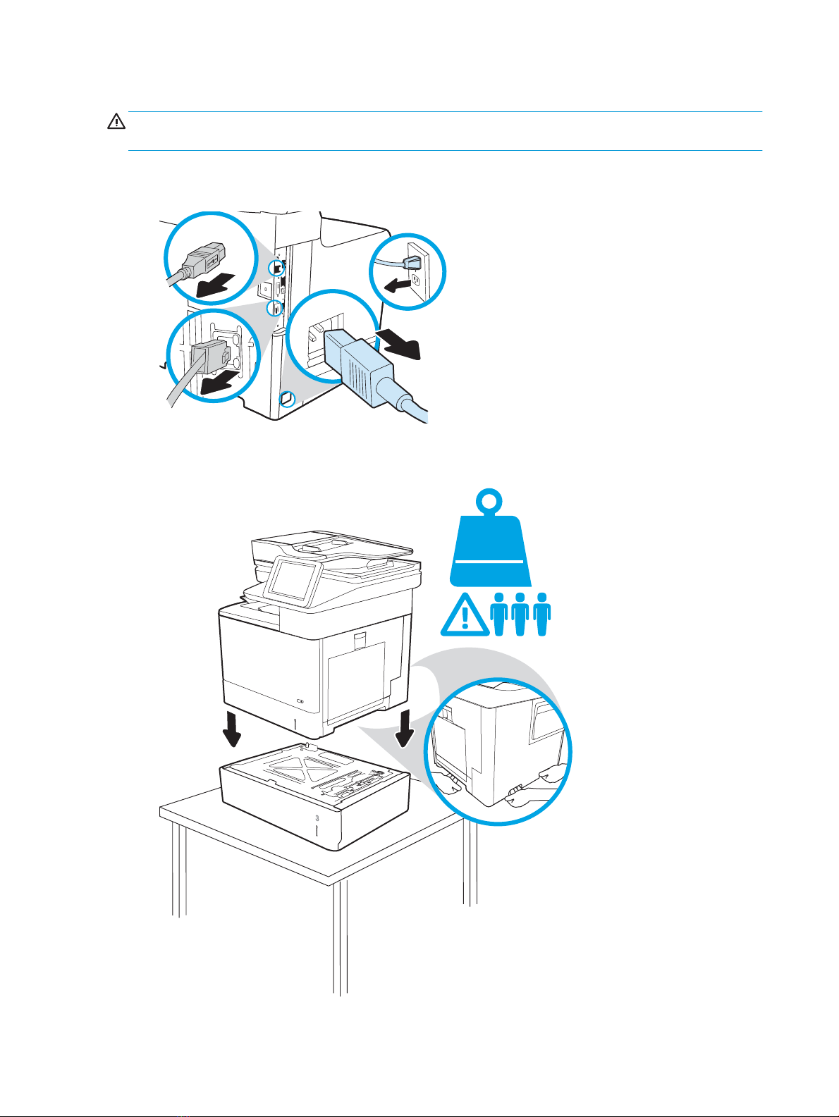
Step 2: Install the 1x550-sheet paper feeder
1
2
42.5 kg
93.6 lb
CAUTION: Do not extend more than one paper tray at a time. Do not use paper tray as a step. Keep hands out
of paper trays when closing. All trays must be closed when moving the printer.
1. Unplug all of the cables attached to the printer.
Figure 1-3 Unplug all of the cables
2
. Place the paper feeder on a sturdy, level surface. Lift the printer and place it on top of the paper feeder.
Figure
Place the printer on the paper feeder
1-4
10 Chapter 1 Removal and replacement ENWW
Page 93

3. Remove the paper tray in the paper feeder, and then engage two locks at the front of the tray opening to
secure the printer to the paper feeder.
Figure 1-5 Engage two locks
4
. Before loading paper, open the paper guides by squeezing the blue adjustment latches and sliding the
guides out as far as they will go.
Figure
Open the paper guides
1-6
ENWW Removal and replacement procedures 11
Page 94
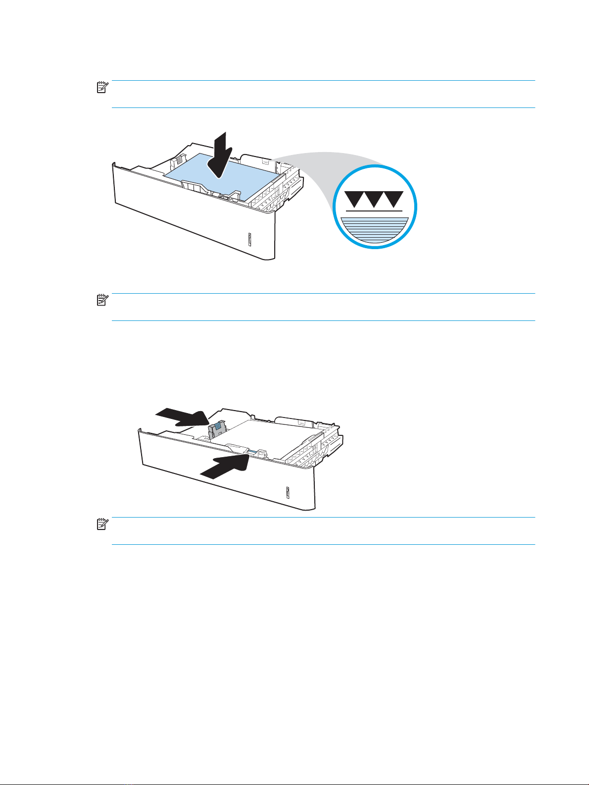
5. Load paper into the tray.
NOTE: To prevent jams, do not overfil the tray. Be sure that the top of the stack is below the tray full
indicator.
Figure 1-7 Load paper into the tray
6. Adjust the paper guides so that the guides lightly touch the stack, but do not bend it.
NOTE: Do not adjust the paper guides tightly against the paper stack. Adjust them to the indentations or
markings in the tr
1-8
Figure
ay.
Adjust the paper guides
NOTE: If the tray requires
order a new fixe tray guide kit: 3GY25-90908 Kit-Fixed Tray Guide. Only one kit is required per engine.
12 Chapter 1 Removal and replacement ENWW
fixe tray guides installed, move that hardware to the new tray. If necessary,
Page 95

7. If necessary, remove the paper tray number indicator on the tray, and then rotate the indicator so that the
tray number correctly reflect the printer's tray configuration Install the indicator in the tray with the
correct tray number facing outward.
Figure 1-9 Remove the paper tray number indicator
. Install the paper tray.
8
1-10
Figure
Install the paper tray
ENWW Removal and replacement procedures 13
Page 96

Install accessory: 1x550-sheet paper feeder with stand
●
Introduction
●
Step 1: Unpack the accessory
●
Step 2: Install the 1x550-sheet paper feeder with stand
Introduction
This document provides the procedures to install the 1x550-sheet paper feeder with stand.
IMPORTANT: When applicable, special installation instructions are provided for an assembly at the end of the
removal procedure. Always completely read the removal instructions and follow all special installation
instructions.
Before performing service
○ Turn the printer power off
○ Disconnect the power cable.
WARNING! To avoid damage to the printer, turn the printer
power cable before attempting to service the printer.
Use the table below to identify the correct part number for your printer. To order the part, go to
www.hp.com/buy/parts
1x550-sheet paper feeder with stand part number
P1B10-67901 1x550 sheet stand
Required tools
● No special tools are needed to remove or install this assembly.
After performing service
Turn the printer power on
○ Connect the power cable.
○ Use the power switch to turn the power on.
Post service test
Make sure that the printer initializes to a
off wait 30 seconds, and then remove the
Ready state.
Print a page from the feeder to make sure that the printer is functioning correctly.
Step 1: Unpack the accessory
Remove the new part from its package. Save all packaging for recycling.
For complete information on HP's recycling programs, go to
Product return and recycling.
14 Chapter 1 Removal and replacement ENWW
Page 97
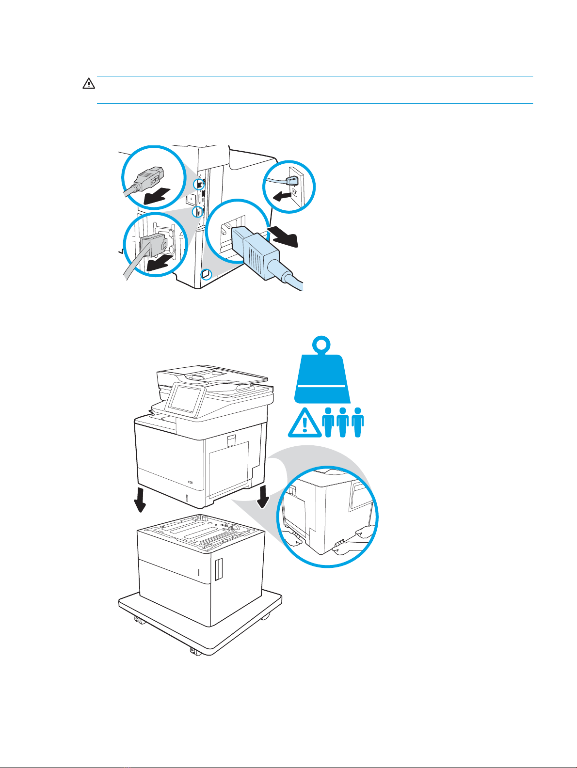
Step 2: Install the 1x550-sheet paper feeder with stand
1
2
42.5kg
93.6 lb
CAUTION: Do not extend more than one paper tray at a time. Do not use paper tray as a step. Keep hands out
of paper trays when closing. All trays must be closed when moving the printer.
1. Unplug all of the cables attached to the printer.
Figure 1-11 Unplug all of the cables
2
. Lift the printer and place it on top of the paper feeder.
Figure
Place the printer on the paper feeder
1-12
ENWW Removal and replacement procedures 15
Page 98

3. Remove the paper tray in the paper feeder, and then engage one lock at the front of the tray opening to
secure the printer to the paper feeder.
Figure 1-13 Engage one lock
4. Locate the orange shipping lock inside the paper tray. Twist the lock to release it, and then lift it straight up
to remove it. Remove all other packing material inside the tray.
Figure 1-14 Remove the orange shipping lock
16 Chapter 1 Removal and replacement ENWW
Page 99

5. Before loading paper, open the paper guides by squeezing the blue adjustment latches and sliding the
guides out as far as they will go.
Figure 1-15 Open the paper guides
6
. Load paper into the tray.
NOTE: To prevent jams, do not overfil the tray. Be sure that the top of the stack is below the tray full
indica
tor.
Figure
Load paper into the tray
1-16
ENWW Removal and replacement procedures 17
Page 100
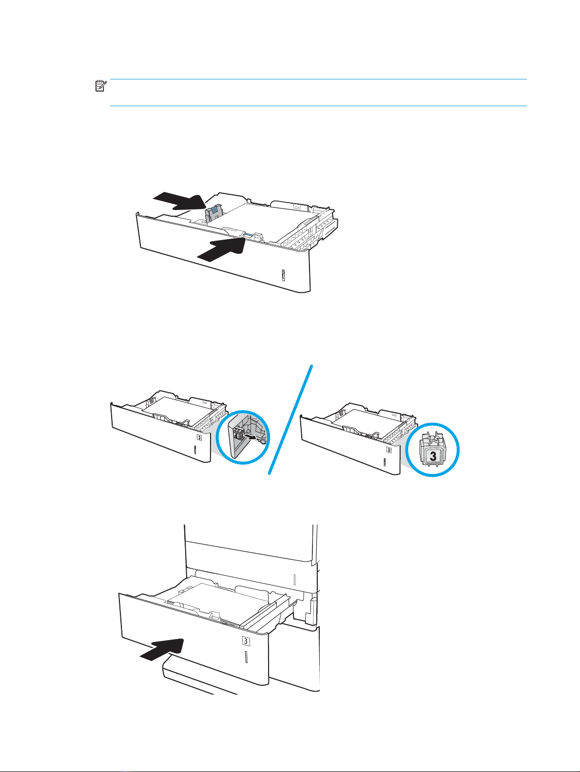
7. Adjust the paper guides so that the guides lightly touch the stack, but do not bend it.
NOTE: Do not adjust the paper guides tightly against the paper stack. Adjust them to the indentations or
markings in the tray.
Figure 1-17 Adjust the paper guides
. If necessary, remove the paper tray number indicator on the tray, and then rotate the indicator so that the
8
tray number correctly reflect the printer's tray configuration Install the indicator in the tray with the
correct tray number facing outward.
1-18
Figure
9
. Install the paper tray.
Figure
Remove the paper tray number indicator
Install the paper tray
1-19
18 Chapter 1 Removal and replacement ENWW
 Loading...