

Page 1
Color LaserJet Enterprise M651
Color LaserJet Enterprise MFP M680
Troubleshooting Manual
M651dn
M651xhM651n
M680zM680fM680dn
www.hp.com/support/colorljM651
www.hp.com/support/colorljMFPM680
Page 2

Page 3

HP Color LaserJet Enterprise M651 and MFP
M680
Troubleshooting Manual
Page 4

Copyright and License
© 2014 Copyright Hewlett-Packard
Development Company, L.P.
Reproduction, adaptation, or translation
without prior written permission is prohibited,
except as allowed under the copyright laws.
The information contained herein is subject to
change without notice.
The only warranties for HP products and
services are set forth in the express warranty
statements accompanying such products and
services. Nothing herein should be construed
as constituting an additional warranty. HP shall
not be liable for technical or editorial errors or
omissions contained herein.
Edition 1, 4/2014
Page 5

Conventions used in this guide
TIP: Helpful hints or shortcuts.
Reinstallation tip Reinstallation helpful hints, shortcuts, or considerations.
NOTE: Information that explains a concept or how to complete a task.
IMPORTANT: Information that help the user to avoid potential product error conditions.
CAUTION: Procedures that the user must follow to avoid losing data or damaging the product.
WARNING! Procedures that the user must follow to avoid personal injury, catastrophic loss of data, or
extensive damage to the product.
ENWW iii
Page 6

iv Conventions used in this guide ENWW
Page 7

Table of contents
1 Theory of operation ....................................................................................................................................... 1
Basic operation ...................................................................................................................................................... 2
Sequence of operation ........................................................................................................................ 4
Formatter-control system ..................................................................................................................................... 5
Formatter hardware ............................................................................................................................ 5
Sleep mode ....................................................................................................................... 6
Input/output ...................................................................................................................... 6
CPU .................................................................................................................................... 6
Memory ............................................................................................................................. 6
Firmware ........................................................................................................................... 6
Nonvolatile memory ......................................................................................................... 7
PJL overview ..................................................................................................................... 7
PML .................................................................................................................................... 7
Control panel ....................................................................................................................................... 7
Engine-control system .......................................................................................................................................... 8
DC controller ........................................................................................................................................ 9
Solenoids ......................................................................................................................... 10
Clutches ........................................................................................................................... 10
Switches .......................................................................................................................... 10
Sensors ............................................................................................................................ 11
Motors ............................................................................................................................. 12
Fans ................................................................................................................................. 13
High-voltage power supply ............................................................................................ 14
Low-voltage power supply ............................................................................................. 16
Over-current/over-voltage protection ........................................................ 17
Safety ............................................................................................................ 17
Function ........................................................................................................ 18
Voltage detection ......................................................................................... 18
Sleep (power save) mode ............................................................................. 18
Low-voltage power supply failure ............................................................... 19
Fuser control ................................................................................................................... 19
Fuser temperature control ........................................................................... 20
ENWW v
Page 8

Fuser sleeve temperature protection .......................................................... 20
Failure detection .......................................................................................... 21
Fuser unit identification ............................................................................... 22
Fuser unit life detection ............................................................................... 22
Laser/scanner system ......................................................................................................................................... 23
Laser/scanner failure ........................................................................................................................ 24
Protective-glass cleaners ................................................................................................................. 25
Image-formation system .................................................................................................................................... 26
Image formation process .................................................................................................................. 28
Step 1: Pre-exposure ...................................................................................................... 29
Step 2: Primary charging ................................................................................................ 29
Step 3: Laser-beam exposure ........................................................................................ 30
Step 4: Development ...................................................................................................... 30
Step 5: Primary transfer ................................................................................................. 31
Step 6: Secondary transfer ............................................................................................. 31
Step 7: Separation .......................................................................................................... 32
Step 8: Fusing .................................................................................................................. 32
Step 9: ITB cleaning ........................................................................................................ 33
Step 10: Drum cleaning .................................................................................................. 33
Toner cartridges ................................................................................................................................ 34
Memory tag ..................................................................................................................... 35
Developing unit engagement and disengagement control ........................................... 35
Intermediate transfer belt (ITB) unit ................................................................................................ 37
Primary transfer roller engagement and disengagement control ................................ 37
ITB cleaning mechanism ................................................................................................. 40
Calibration ......................................................................................................................................... 40
Color-misregistration control ........................................................................................ 41
Image stabilization control ............................................................................................. 42
Pickup, feed, and delivery system ...................................................................................................................... 43
Pickup-and-feed unit ........................................................................................................................ 48
Cassette pickup ............................................................................................................... 48
Cassette-presence detection ....................................................................... 49
Cassette lift operation and cassette paper-presence detection ................ 50
Cassette multiple-feed prevention .............................................................. 51
Multipurpose tray pickup ................................................................................................ 51
Paper feed ....................................................................................................................... 52
Skew-feed prevention .................................................................................. 54
Paper detection ............................................................................................ 55
Feed speed control ....................................................................................... 55
Fusing and delivery block ................................................................................................................. 56
Loop control .................................................................................................................... 57
vi ENWW
Page 9

Pressure roller pressurization and depressurization control ....................................... 58
Duplex Block ...................................................................................................................................... 59
Duplex reverse and duplex feed control ........................................................................ 60
Duplex operation ............................................................................................................ 61
Jam detection .................................................................................................................................... 62
Optional paper feeders ........................................................................................................................................ 64
Motor control ..................................................................................................................................... 68
Paper-feeder pickup and feed operation ......................................................................................... 69
Paper-size detection and cassette-presence detection .................................................................. 71
Paper-feeder cassette lift operation ................................................................................................ 73
Paper feeder jam detection .............................................................................................................. 74
Scanning/image capture system (M680) ............................................................................................................ 77
Scanner .............................................................................................................................................. 77
Document feed system ..................................................................................................................... 77
Sensors in the automatic document feeder ................................................................... 77
Automatic document feeder paper path ........................................................................ 79
Automatic document feeder simplex operation ............................................................ 79
Automatic document feeder e-duplex operation .......................................................... 80
Front-side and back-side background selector ............................................................. 81
Deskew operation ........................................................................................................... 82
Automatic document feeder hinges ............................................................................... 83
Stapling mailbox (M680) ..................................................................................................................................... 85
Motor control ..................................................................................................................................... 87
Failure detection ............................................................................................................................... 87
Delivery operation ............................................................................................................................. 88
Staple operation ............................................................................................................. 90
Stapler ............................................................................................................................. 94
Output bin 3 lift operation .............................................................................................. 95
Stacker mode .................................................................................................................................... 96
Mailbox/job separator mode ............................................................................................................ 97
Jam detection .................................................................................................................................... 98
Automatic delivery ............................................................................................................................ 99
2 Solve problems .......................................................................................................................................... 101
Solve problems checklist .................................................................................................................................. 102
Menu map .......................................................................................................................................................... 105
Current settings pages ...................................................................................................................................... 105
Event log ............................................................................................................................................................ 105
Pre-boot menu options ..................................................................................................................................... 107
Remote Admin ................................................................................................................................. 115
Required software and network connection ................................................................ 115
ENWW vii
Page 10

Telnet client ................................................................................................ 116
Network connection ................................................................................... 117
Connect a remote connection ...................................................................................... 117
Disconnect a remote connection .................................................................................. 122
Troubleshooting process .................................................................................................................................. 124
Determine the problem source ....................................................................................................... 124
Troubleshooting flowchart .......................................................................................... 124
Power subsystem ............................................................................................................................ 125
Power-on checks .......................................................................................................... 125
Power-on troubleshooting overview ......................................................... 125
Scanning subsystem (M680) ........................................................................................................... 129
Control panel checks ....................................................................................................................... 129
Control panel diagnostic flowcharts ............................................................................ 133
Touchscreen black, white, or dim (no image) ............................................ 134
Touchscreen is slow to respond or requires multiple presses to
respond ....................................................................................................... 135
Touchscreen has an unresponsive zone .................................................... 136
No control panel sound .............................................................................. 137
Home button is unresponsive .................................................................... 138
Hardware integration pocket (HIP) is not functioning (control panel
functional) .................................................................................................. 139
Tools for troubleshooting ................................................................................................................................. 140
Individual component diagnostics .................................................................................................. 140
LED diagnostics ............................................................................................................. 140
Understand lights on the formatter .......................................................... 140
Engine diagnostics ........................................................................................................ 145
Defeating interlocks ................................................................................... 145
Disable cartridge check .............................................................................. 146
Engine test button ...................................................................................... 147
Paper path test ............................................................................................................. 148
Paper path sensors test ............................................................................................... 148
Manual sensor and tray/bin manual sensor tests ....................................................... 150
Manual sensor test ..................................................................................... 150
Tray/bin manual sensor test ...................................................................... 152
Print/stop test .............................................................................................................. 154
Component tests .......................................................................................................... 155
Component test (special-mode test) ......................................................... 155
Scanner tests (M680) .................................................................................................... 158
Scanner tests .............................................................................................. 158
Diagrams ......................................................................................................................................... 160
Block Diagrams ............................................................................................................. 160
viii ENWW
Page 11

Sensors and switches ................................................................................. 160
Cross section diagrams .............................................................................. 165
Location of connectors ................................................................................................. 169
DC controller PCA ....................................................................................... 169
Intermediate paper transport unit (ITPU) driver PCA (M680) ................... 172
Accessories controller PCA ......................................................................... 173
3-bin stapling mailbox accessory (M680) ................................................. 174
Formatter connections ................................................................................................. 176
Location of major components .................................................................................... 178
Base product .............................................................................................. 178
1x500-sheet paper feeder ......................................................................... 181
1x500-sheet paper deck ............................................................................ 182
2,500-sheet high-capacity feeder (HCI) .................................................... 183
3-bin stapling mailbox accessory (M680) ................................................. 184
General timing chart ..................................................................................................... 185
Circuit diagrams ............................................................................................................ 186
Internal print-quality test pages .................................................................................................... 191
Print quality troubleshooting pages ............................................................................ 191
Print quality assessment page ..................................................................................... 194
Cleaning page ............................................................................................................... 196
Enable and configure auto cleaning .......................................................... 196
Print a configuration page ............................................................................................ 197
Configuration page ..................................................................................... 197
HP embedded Jetdirect page ..................................................................... 200
Finding important information on the configuration pages ..................... 202
Color band test ............................................................................................................. 202
Print quality troubleshooting tools ................................................................................................ 203
Print quality troubleshooting tools: repetitive defects ruler ...................................... 203
Calibrate the product to align the colors ..................................................................... 204
Control-panel menus ...................................................................................................................... 205
Administration menu .................................................................................................... 205
Reports menu ............................................................................................. 205
General Settings menu ............................................................................... 208
Copy Settings menu (M680 only) ............................................................... 222
Scan/Digital Send Settings menu (M680) .................................................. 229
Fax Settings menu (M680) ......................................................................... 240
General Print Settings menu ...................................................................... 253
Default Print Options menu ....................................................................... 256
Display Settings menu ............................................................................... 258
Manage Supplies menu .............................................................................. 260
Manage Trays menu ................................................................................... 266
ENWW ix
Page 12

Network Settings menu ............................................................................. 268
Troubleshooting menu ............................................................................... 280
Device Maintenance menu ............................................................................................ 284
Backup/Restore menu ............................................................................... 284
Calibration/Cleaning menu (M680) ............................................................ 285
Calibration/Cleaning menu (M651) ............................................................ 288
USB Firmware Upgrade menu .................................................................... 289
Service menu .............................................................................................. 289
Print quality troubleshooting tools: interpret control-panel messages and event log entries . . . 290
Control-panel message types ...................................................................................... 290
Control-panel messages and event log entries ........................................................... 290
10.XX.YZ Error Messages ........................................................................... 290
11.XX.YZ Error Messages ........................................................................... 298
13.WX.YZ Error Messages .......................................................................... 298
20.XX.YY and 21.XX.YY .............................................................................. 318
30.XX.YZ Error Messages ........................................................................... 319
31.XX.YZ Error Messages ........................................................................... 326
32.08.XX Error Messages ........................................................................... 332
33.XX.YZ Error Messages ........................................................................... 337
41.XX.YZ Error Messages ........................................................................... 340
42.XX.YY Error Messages ........................................................................... 348
44.XX.XX Error Messages ........................................................................... 349
47.XX.XX Error Messages ........................................................................... 350
48.XX.YY Error Messages ........................................................................... 352
49.XX.YY Error Messages ........................................................................... 353
50.WX.YZ Error Messages .......................................................................... 354
51.XX.YZ, 52.XX.YZ Error Messages .......................................................... 360
54.XX.YZ Error Messages ........................................................................... 361
55.XX.YZ, 56.XX.YZ Error Messages .......................................................... 364
57.XX.YZ Error Messages ........................................................................... 365
58.XX.YY & 59.XX.YZ Error Messages ........................................................ 367
60.00.0Y, 62.00.00 Error Messages .......................................................... 371
65.X0.AZ Error Messages ........................................................................... 373
70.XX.YY Error Messages ........................................................................... 374
80.XX.YY, 82.XX.YY Error Messages .......................................................... 374
98.0X.0Y Error Messages ........................................................................... 375
99.XX.YY Error Messages ........................................................................... 376
Alpha Error Messages ................................................................................. 384
Print quality troubleshooting tools: event log messages ............................................................. 430
Print or view an event log ............................................................................................. 431
Clear the event log ........................................................................................................ 431
x ENWW
Page 13

Clear jams .......................................................................................................................................................... 432
Auto-navigation for clearing jams .................................................................................................. 432
Experiencing frequent or recurring paper jams? ............................................................................ 432
Jam sensor locations ...................................................................................................................... 433
Paper path sensor locations ......................................................................................... 433
Jam locations (M680) ...................................................................................................................... 438
Jam locations (M651) ...................................................................................................................... 439
Clear jams in Tray 1 ......................................................................................................................... 440
Clear jams in Tray 2 and the 500-sheet trays ................................................................................ 442
Clear jams in the 1,500-sheet high-capacity input tray and the lower-right door ....................... 447
Clear jams in the lower-right door .................................................................................................. 451
Clear jams in the right door and the fuser area .............................................................................. 452
Clear jams from under the top cover (M680) ................................................................................. 455
Clear jams in the document feeder (M680) .................................................................................... 456
Clear jams in the output bin (M680) ............................................................................................... 460
Clear jams in the output bin (M651) ............................................................................................... 460
Clear jams in the stapling mailbox accessory (M680) .................................................................... 461
Clear staple jams in the stapling mailbox accessory (M680) ......................................................... 463
Change jam recovery ....................................................................................................................... 466
Paper feeds incorrectly or becomes jammed ................................................................................................... 467
The product does not pick up paper ............................................................................................... 467
The product picks up multiple sheets of paper .............................................................................. 467
The document feeder jams, skews, or picks up multiple sheets of paper (M880) ........................ 468
Prevent paper jams ......................................................................................................................... 468
Use manual print modes ................................................................................................................................... 469
Solve image quality problems .......................................................................................................................... 473
Image defects table ........................................................................................................................ 473
Clean the product .............................................................................................................................................. 491
Print a cleaning page ...................................................................................................................... 491
Check the scanner glass for dirt or smudges (M680) ..................................................................... 492
Clean the pickup rollers and separation pad in the document feeder (M680) .............................. 494
Clean the pickup, feed, and separation rollers in the 1x500-sheet paper-feeder and 1x500-
sheet paper-feeder with storage cabinet ...................................................................................... 496
Clean the pickup, feed, and separation rollers in the 2,500-sheet high-capacity feeder (HCI) .... 497
Solve performance problems ............................................................................................................................ 498
Solve connectivity problems ............................................................................................................................. 499
Solve USB connection problems ..................................................................................................... 499
Solve wired network problems ....................................................................................................... 499
Poor physical connection ............................................................................................. 499
The computer is using the incorrect IP address for the product ................................. 499
The computer is unable to communicate with the product ........................................ 500
ENWW xi
Page 14

The product is using incorrect link and duplex settings for the network ................... 500
New software programs might be causing compatibility problems ........................... 500
The computer or workstation might be set up incorrectly .......................................... 500
The product is disabled, or other network settings are incorrect ............................... 500
Service mode functions ..................................................................................................................................... 501
Service menu ................................................................................................................................... 501
Product resets ................................................................................................................................. 506
Restore factory-set defaults ........................................................................................ 506
Restore the service ID ................................................................................................... 507
Product cold reset ........................................................................................................ 507
Format Disk and Partial Clean functions ........................................................................................ 508
Active and repository firmware locations .................................................................... 508
Partial Clean .................................................................................................................. 508
Execute a Partial Clean ............................................................................... 509
Format Disk ................................................................................................................... 509
Execute a Format Disk ................................................................................ 510
Solve fax problems (M680) ............................................................................................................................... 511
Checklist for solving fax problems ................................................................................................. 511
What type of phone line are you using? ....................................................................... 511
Are you using a surge-protection device? .................................................................... 511
Are you using a phone company voice-messaging service or an answering
machine? ....................................................................................................................... 511
Does your phone line have a call-waiting feature? ..................................................... 511
Check fax accessory status .......................................................................................... 512
General fax problems ...................................................................................................................... 513
The fax failed to send ................................................................................................... 513
An Out of Memory status message displays on the product control panel ................ 513
Print quality of a photo is poor or prints as a gray box ............................................... 513
You touched the Stop button to cancel a fax, but the fax was still sent ..................... 513
No fax address book button displays ........................................................................... 513
Not able to locate the Fax settings in HP Web Jetadmin ............................................. 513
The header is appended to the top of the page when the overlay option is enabled 513
A mix of names and numbers is in the recipients box ................................................. 513
A one-page fax prints as two pages ............................................................................. 514
A document stops in the document feeder in the middle of faxing ............................ 514
The volume for sounds coming from the fax accessory is too high or too low .......... 514
Use Fax over VoIP networks ........................................................................................................... 515
Problems with receiving faxes ........................................................................................................ 516
Problems with sending faxes ......................................................................................................... 518
Fax error messages on the product control panel ......................................................................... 519
Send-fax messages ...................................................................................................... 520
xii ENWW
Page 15

Receive-fax messages .................................................................................................. 521
Service settings ............................................................................................................................... 522
Settings in the Troubleshooting menu ........................................................................ 522
Firmware upgrades ........................................................................................................................................... 523
Determine the installed revision of firmware ................................................................................ 523
Perform a firmware upgrade .......................................................................................................... 523
HP Embedded Web Server ............................................................................................ 523
USB flash drive (Pre-boot menu) ................................................................................. 524
USB flash drive (control-panel menu) .......................................................................... 525
Appendix A Product specifications ................................................................................................................. 527
Product dimensions ........................................................................................................................................... 528
Product space requirements ............................................................................................................................. 529
Power consumption, electrical specifications, and acoustic emissions .......................................................... 530
Environmental specifications ............................................................................................................................ 530
Certificate of Volatility ...................................................................................................................................... 531
Index ........................................................................................................................................................... 535
ENWW xiii
Page 16

xiv ENWW
Page 17

List of tables
Table 1-1 Sequence of operation ......................................................................................................................................... 4
Table 1-2 Formatter hardware components ....................................................................................................................... 5
Table 1-3 Solenoids ............................................................................................................................................................ 10
Table 1-4 Clutches .............................................................................................................................................................. 10
Table 1-5 Switches ............................................................................................................................................................. 10
Table 1-6 Sensors ............................................................................................................................................................... 11
Table 1-7 Motors ................................................................................................................................................................ 12
Table 1-8 Fans .................................................................................................................................................................... 13
Table 1-9 High-voltage power supply circuits ................................................................................................................... 14
Table 1-10 Converted DC voltages ..................................................................................................................................... 17
Table 1-11 Low-voltage power supply functions .............................................................................................................. 18
Table 1-12 Fuser components ........................................................................................................................................... 19
Table 1-13 Image formation process ................................................................................................................................. 28
Table 1-14 Primary-transfer roller engagement states ................................................................................................... 38
Table 1-15 Image-stabilization controls ........................................................................................................................... 42
Table 1-16 Switches and sensors for the pickup, feed, and delivery system ................................................................... 45
Table 1-17 Motors and solenoids for the pickup, feed, and delivery system ................................................................... 46
Table 1-18 Cassette-presence detection ........................................................................................................................... 49
Table 1-19 Print mode and feed speed .............................................................................................................................. 55
Table 1-20 Paper sizes ....................................................................................................................................................... 61
Table 1-21 Jams that the product detects ......................................................................................................................... 63
Table 1-22 Electrical components for the paper feeder ................................................................................................... 65
Table 1-23 Electrical components for the 2,500-sheet paper feeder HCI ........................................................................ 67
Table 1-24 Motor control (1x500-sheet paper feeder) ..................................................................................................... 68
Table 1-25 Motor control (2,500-sheet paper feeder HCI) ................................................................................................ 68
Table 1-26 Pickup feed components (1x500-sheet paper feeder) ................................................................................... 69
Table 1-27 Pickup feed components (2,500-sheet paper feeder HCI) .............................................................................. 70
Table 1-28 Paper-size detection and cassette-presence detection (1 x 500 paper feeder) ............................................ 71
Table 1-29 Paper-size detection and cassette-presence detection (2,500-sheet paper feeder HCI) ............................. 72
Table 1-30 Automatic document feeder sensors .............................................................................................................. 78
Table 1-31 Automatic document feeder paper path ......................................................................................................... 79
Table 1-32 Automatic document feeder deskew features ................................................................................................ 82
ENWW xv
Page 18

Table 1-33 Electrical components for the stapling mailbox ............................................................................................. 86
Table 1-34 Motor control (stapling mailbox) ..................................................................................................................... 87
Table 1-35 Delivery components (stapling mailbox) ........................................................................................................ 88
Table 2-1 Pre-boot menu options (1 of 7) ....................................................................................................................... 107
Table 2-2 Pre-boot menu options (2 of 7) ....................................................................................................................... 109
Table 2-3 Pre-boot menu options (3 of 7) ....................................................................................................................... 110
Table 2-4 Pre-boot menu options (4 of 7) ....................................................................................................................... 111
Table 2-5 Pre-boot menu options (5 of 7) ....................................................................................................................... 111
Table 2-6 Pre-boot menu options (6 of 7) ....................................................................................................................... 113
Table 2-7 Pre-boot menu options (7 of 7) ....................................................................................................................... 114
Table 2-8 Troubleshooting flowchart .............................................................................................................................. 124
Table 2-9 Control panel diagnostic functions .................................................................................................................. 130
Table 2-10 Connectivity LED, product initialization ........................................................................................................ 141
Table 2-11 Connectivity LED, product operational .......................................................................................................... 143
Table 2-12 Paper-path sensors diagnostic tests ............................................................................................................ 148
Table 2-13 Manual sensor diagnostic tests ..................................................................................................................... 150
Table 2-14 Tray/bin manual sensors ............................................................................................................................... 152
Table 2-15 Component test details ................................................................................................................................. 155
Table 2-16 Sensors and switches (product; M651) ......................................................................................................... 160
Table 2-17 Sensors and switches (product; M680) ......................................................................................................... 161
Table 2-18 1x500-sheet paper-feeder and 1x500-sheet paper-feeder with storage cabinet sensors and switches .. 162
Table 2-19 2,500-sheet paper deck (HCI) sensors and switches .................................................................................... 163
Table 2-20 3-bin stapling mailbox accessory sensors and switches (M680) ................................................................. 164
Table 2-21 Product base .................................................................................................................................................. 165
Table 2-22 1x500-sheet paper-feeder and 1x500-sheet paper-feeder with storage cabinet
1
.................................... 166
Table 2-23 2,500-sheet high-capacity feeder (HCI) sensors and switches .................................................................... 167
Table 2-24 3-bin stapling mailbox accessory (M680) ..................................................................................................... 168
Table 2-25 DC controller connectors ............................................................................................................................... 169
Table 2-26 Intermediate paper transport unit (ITPU) driver PCA (M680) ....................................................................... 172
Table 2-27 Accessories controller PCA ............................................................................................................................ 173
Table 2-28 3-bin stapling mailbox accessory (M680) ..................................................................................................... 174
Table 2-29 Formatter connections (M651) ...................................................................................................................... 176
Table 2-30 Formatter connections (M680) ...................................................................................................................... 176
Table 2-31 M680 product integrated scanner assembly (ISA) ........................................................................................ 178
Table 2-32 Base product external view M651 ................................................................................................................. 179
Table 2-33 Base product external view M680 ................................................................................................................. 180
Table 2-34 1x500-sheet paper feeder ............................................................................................................................. 181
Table 2-35 1x500-sheet paper deck ................................................................................................................................ 182
Table 2-36 2,500-sheet high-capacity feeder (HCI) ........................................................................................................ 183
Table 2-37 3-bin stapling mailbox accessory (M680) ..................................................................................................... 184
Table 2-38 Configuration page ........................................................................................................................................ 198
xvi ENWW
Page 19

Table 2-39 HP embedded Jetdirect page ......................................................................................................................... 200
Table 2-40 Important information on the configuration pages ...................................................................................... 202
Table 2-41 Reports menu ................................................................................................................................................. 206
Table 2-42 General Settings menu .................................................................................................................................. 208
Table 2-43 Copy Settings menu (M680) .......................................................................................................................... 222
Table 2-44 Scan/Digital Send Settings menu (M680) ..................................................................................................... 229
Table 2-45 Fax Settings menu (M680) ............................................................................................................................. 240
Table 2-46 General Print Settings menu ......................................................................................................................... 253
Table 2-47 Default Print Options menu ........................................................................................................................... 256
Table 2-48 Display Settings menu ................................................................................................................................... 258
Table 2-49 Manage Supplies menu .................................................................................................................................. 260
Table 2-50 Manage Trays menu ....................................................................................................................................... 266
Table 2-51 Network Settings menu ................................................................................................................................. 268
Table 2-52 Jetdirect Menu ................................................................................................................................................ 268
Table 2-53 Troubleshooting menu .................................................................................................................................. 280
Table 2-54 Backup/Restore menu ................................................................................................................................... 284
Table 2-55 Calibration/Cleaning menu (M680) ............................................................................................................... 285
Table 2-56 Calibration/Cleaning menu (M651) ............................................................................................................... 288
Table 2-57 Sensors and switches (product; M651) ......................................................................................................... 433
Table 2-58 Sensors and switches (product; M680) ......................................................................................................... 434
Table 2-59 1x500-sheet paper-feeder and 1x500-sheet paper-feeder with storage cabinet sensors and
switches ............................................................................................................................................................................... 435
Table 2-60 2,500-sheet paper deck (HCI) sensors and switches .................................................................................... 436
Table 2-61 3-bin stapling mailbox accessory sensors and switches (M680) ................................................................. 437
Table 2-62 Print modes
1
under the Adjust Paper Types submenu ................................................................................. 470
Table 2-63 Print modes under the Optimize submenu ................................................................................................... 471
Table 2-64 Image defects table ....................................................................................................................................... 473
Table 2-65 Solve performance problems ........................................................................................................................ 498
Table 2-66 Service menu (M651 and M680) .................................................................................................................... 501
Table 2-67 Service menu (M680 only) ............................................................................................................................. 505
Table 2-68 Send-fax messages ....................................................................................................................................... 520
Table 2-69 Receive-fax messages ................................................................................................................................... 521
Table A-1 Physical specifications, with toner cartridges (M680) .................................................................................... 528
Table A-2 Physical specifications, with toner cartridge (M651) ...................................................................................... 528
Table A-3 Product dimensions with all doors, trays, and document feeder fully opened (M680) ................................. 528
Table A-4 Product dimensions with all doors and trays fully opened (M651) ................................................................ 528
Table A-5 Accessory dimensions ...................................................................................................................................... 528
Table A-6 Product space requirements ........................................................................................................................... 529
Table A-7 Operating-environment specifications ........................................................................................................... 530
ENWW xvii
Page 20

xviii ENWW
Page 21

List of figures
Figure 1-1 Relationship between the main product systems .............................................................................................. 2
Figure 1-2 System block diagram ........................................................................................................................................ 3
Figure 1-3 Engine-control system ........................................................................................................................................ 8
Figure 1-4 DC controller block diagram ............................................................................................................................... 9
Figure 1-5 High-voltage power supply circuits .................................................................................................................. 14
Figure 1-6 Low-voltage power-supply circuit ................................................................................................................... 16
Figure 1-7 Fuser components ............................................................................................................................................ 19
Figure 1-8 Fuser temperature-control circuit .................................................................................................................... 20
Figure 1-9 Laser/scanner system ...................................................................................................................................... 23
Figure 1-10 Protective-glass cleaners (PGCs) ................................................................................................................... 25
Figure 1-11 Image-formation system ............................................................................................................................... 26
Figure 1-12 Image-formation drive system ...................................................................................................................... 27
Figure 1-13 Image-formation process ............................................................................................................................... 28
Figure 1-14 Pre-exposure .................................................................................................................................................. 29
Figure 1-15 Primary charging ............................................................................................................................................ 29
Figure 1-16 Laser-beam exposure ..................................................................................................................................... 30
Figure 1-17 Development .................................................................................................................................................. 30
Figure 1-18 Primary transfer ............................................................................................................................................. 31
Figure 1-19 Secondary transfer ......................................................................................................................................... 31
Figure 1-20 Separation ....................................................................................................................................................... 32
Figure 1-21 Fusing .............................................................................................................................................................. 32
Figure 1-22 ITB cleaning ..................................................................................................................................................... 33
Figure 1-23 Drum cleaning ................................................................................................................................................. 33
Figure 1-24 Toner cartridge system .................................................................................................................................. 34
Figure 1-25 Developing-roller engagement and disengagement control ........................................................................ 35
Figure 1-26 ITB unit ............................................................................................................................................................ 37
Figure 1-27 Three states of primary-transfer roller engagement and disengagement .................................................. 39
Figure 1-28 ITB cleaning process ....................................................................................................................................... 40
Figure 1-29 Toner patterns for calibration ........................................................................................................................ 41
Figure 1-30 Paper path ....................................................................................................................................................... 43
Figure 1-31 Switches and sensors for the pickup, feed, and delivery system (M651 only) ............................................. 44
Figure 1-32 Switches and sensors for the pickup, feed, and delivery system (M680 only) ............................................. 44
ENWW xix
Page 22

Figure 1-33 Motors and solenoids for the pickup, feed, and delivery system .................................................................. 46
Figure 1-34 Three main units of the pickup, feed, and delivery system ........................................................................... 47
Figure 1-35 Pickup-and-feed unit ...................................................................................................................................... 48
Figure 1-36 Cassette-pickup mechanism .......................................................................................................................... 49
Figure 1-37 Cassette lift mechanism ................................................................................................................................. 50
Figure 1-38 Multiple-feed prevention ................................................................................................................................ 51
Figure 1-39 Multipurpose tray pickup mechanism ............................................................................................................ 52
Figure 1-40 Paper-feed mechanism .................................................................................................................................. 53
Figure 1-41 Skew-feed prevention .................................................................................................................................... 54
Figure 1-42 Fuser and delivery unit ................................................................................................................................... 56
Figure 1-43 Loop-control mechanism ............................................................................................................................... 57
Figure 1-44 Pressure-roller pressurization control .......................................................................................................... 58
Figure 1-45 Duplexing unit ................................................................................................................................................. 59
Figure 1-46 Duplex reverse and feed control .................................................................................................................... 60
Figure 1-47 Jam detection sensors .................................................................................................................................... 62
Figure 1-48 1 x 500 optional paper feeder ........................................................................................................................ 64
Figure 1-49 Signals for the paper feeder ........................................................................................................................... 65
Figure 1-50 2,500-sheet paper feeder HCI ........................................................................................................................ 66
Figure 1-51 Signals for 2,500-sheet paper feeder HCI ...................................................................................................... 67
Figure 1-52 Paper-feeder pickup and feed operation (1x500-sheet paper feeder) ........................................................ 69
Figure 1-53 Paper-feeder pickup and feed operation (2,500-sheet paper feeder HCI) ................................................... 70
Figure 1-54 Paper-feeder cassette lift .............................................................................................................................. 73
Figure 1-55 Jam detection (1x500-sheet paper feeder) ................................................................................................... 74
Figure 1-56 2,500-sheet paper feeder HCI media feed sensors ....................................................................................... 75
Figure 1-57 Automatic document feeder sensors ............................................................................................................. 78
Figure 1-58 Automatic document feeder paper path ........................................................................................................ 79
Figure 1-59 Automatic document feeder deskew features .............................................................................................. 82
Figure 1-60 Automatic document feeder open (book mode) ............................................................................................ 83
Figure 1-61 Automatic document feeder open (60º to 80º) .............................................................................................. 84
Figure 1-62 Stapling mailbox ............................................................................................................................................. 85
Figure 1-63 Signals for the stapling mailbox ..................................................................................................................... 85
Figure 1-64 Stapling mailbox delivery operation .............................................................................................................. 88
Figure 1-65 Stapling mailbox stapler operation (1 of 4) ................................................................................................... 90
Figure 1-66 Stapling mailbox stapler operation (2 of 4) ................................................................................................... 91
Figure 1-67 Stapling mailbox stapler operation (3 of 4) ................................................................................................... 92
Figure 1-68 Stapling mailbox stapler operation (4 of 4) ................................................................................................... 93
Figure 1-69 Stapling mailbox sensors for the stapler ....................................................................................................... 94
Figure 1-70 Stapling mailbox sensors for output bin 3 lift operation .............................................................................. 95
Figure 1-71 Stapling mailbox sensors for stacker mode .................................................................................................. 96
Figure 1-72 Stapling mailbox sensors for mail
Figure 1-73 Stapling mailbox sensors for jam detection .................................................................................................. 98
box/jam separation ................................................................................. 97
xx ENWW
Page 23

Figure 2-1 Open the Control Panel ................................................................................................................................... 116
Figure 2-2 Turn Windows features on or off .................................................................................................................... 116
Figure 2-3 Enable the telnet client feature ..................................................................................................................... 117
Figure 2-4 Select the +3:Administrator item ................................................................................................................... 118
Figure 2-5 Select the +A:Remote Admin item ................................................................................................................. 118
Figure 2-6 Select the 1:Start Telnet item ........................................................................................................................ 118
Figure 2-7 Telnet connecting message ............................................................................................................................ 118
Figure 2-8 Telnet error message ..................................................................................................................................... 119
Figure 2-9 Telnet server function initialized ................................................................................................................... 119
Figure 2-10 Open a command window ............................................................................................................................ 120
Figure 2-11 Start a telnet session .................................................................................................................................... 120
Figure 2-12 Establish a telnet connection ....................................................................................................................... 120
Figure 2-13 Enter the PIN ................................................................................................................................................. 121
Figure 2-14 Remote Admin window ................................................................................................................................. 121
Figure 2-15 Access the administrator menu ................................................................................................................... 122
Figure 2-16 Access the remote admin menu ................................................................................................................... 122
Figure 2-17 Terminate the telnet connection ................................................................................................................. 123
Figure 2-18 M650 control-panel test button location .................................................................................................... 130
Figure 2-19 Touchscreen blank, white, or dim (no image) .............................................................................................. 134
Figure 2-20 Touchscreen is slow to respond or requires multiple presses to respond ................................................. 135
Figure 2-21 Touchscreen has an unresponsive zone ...................................................................................................... 136
Figure 2-22 No control panel sound ................................................................................................................................ 137
Figure 2-23 Home button is unresponsive ...................................................................................................................... 138
Figure 2-24 Hardware integration pocket (HIP) is not functioning (control panel functional) ...................................... 139
Figure 2-25 Defeating interlocks (1 of 2) ......................................................................................................................... 145
Figure 2-26 Defeating interlocks (2 of 2) ......................................................................................................................... 146
Figure 2-27 Engine test button ........................................................................................................................................ 147
Figure 2-28 Sensors and switches (paper path; M651) ................................................................................................... 160
Figure 2-29 Sensors and switches (paper path; M680) ................................................................................................... 161
Figure 2-30 1x500-sheet paper-feeder and 1x500-sheet paper-feeder with storage cabinet sensors and
switches ............................................................................................................................................................................... 162
Figure 2-31 2,500-sheet high-capacity feeder (HCI) sensors and switches ................................................................... 163
Figure 2-32 3-bin stapling mailbox accessory sensors and switches (M680) ................................................................ 164
Figure 2-33 Product base ................................................................................................................................................. 165
Figure 2-34 1x500-sheet paper-feeder and 1x500-sheet paper-feeder with storage cabinet .................................... 166
Figure 2-35 2,500-sheet high-capacity feeder (HCI) sensors and switches ................................................................... 167
Figure 2-36 3-bin stapling mailbox accessory (M680) .................................................................................................... 168
Figure 2-37 DC controller PCA .......................................................................................................................................... 169
Figure 2-38 Intermediate paper transport unit (ITPU) driver PCA (M680) ...................................................................... 172
Figure 2-39 Accessories controller PCA ........................................................................................................................... 173
Figure 2-40 3-bin stapling mailbox accessory (M680) .................................................................................................... 174
ENWW xxi
Page 24

Figure 2-41 Formatter connections (M651) .................................................................................................................... 176
Figure 2-42 Formatter connections (M680) .................................................................................................................... 176
Figure 2-43 M680 product integrated scanner assembly (ISA) ....................................................................................... 178
Figure 2-44 Base product external view M651 ................................................................................................................ 179
Figure 2-45 Base product external view M680 ................................................................................................................ 180
Figure 2-46 1x500-sheet paper feeder ........................................................................................................................... 181
Figure 2-47 1x500-sheet paper deck .............................................................................................................................. 182
Figure 2-48 2,500-sheet high-capacity feeder (HCI) ....................................................................................................... 183
Figure 2-49 3-bin stapling mailbox accessory (M680) .................................................................................................... 184
Figure 2-50 General timing chart ..................................................................................................................................... 185
Figure 2-51 General circuit diagram (M651) .................................................................................................................... 186
Figure 2-52 General circuit diagram (M680; 1 of 2) ......................................................................................................... 187
Figure 2-53 General circuit diagram (M680; 2 of 2) ......................................................................................................... 188
Figure 2-54 1x500-sheet paper feeder, 1x500-sheet paper deck, and 2,500-sheet high-capacity feeder (HCI) ......... 189
Figure 2-55 3-bin stapling mailbox accessory (M680) .................................................................................................... 190
Figure 2-56 Print-quality troubleshooting procedure .................................................................................................... 191
Figure 2-57 Yellow print-quality troubleshooting page ................................................................................................. 192
Figure 2-58 Yellow comparison page .............................................................................................................................. 192
Figure 2-59 Black print-quality troubleshooting page .................................................................................................... 193
Figure 2-60 Configuration page ....................................................................................................................................... 198
Figure 2-61 Configuration page ....................................................................................................................................... 200
Figure 2-62 Repetitive defects ruler ................................................................................................................................ 203
Figure 2-63 Sample event log .......................................................................................................................................... 430
Figure 2-64 Sensors and switches (paper path; M651) ................................................................................................... 433
Figure 2-65 Sensors and switches (paper path; M680) ................................................................................................... 434
Figure 2-66 1x500-sheet paper-feeder and 1x500-sheet paper-feeder with storage cabinet sensors and
switches ............................................................................................................................................................................... 435
Figure 2-67 2,500-sheet high-capacity feeder (HCI) sensors and switches ................................................................... 436
Figure 2-68 3-bin stapling mailbox accessory sensors and switches (M680) ................................................................ 437
Figure A-1 Product space requirements .......................................................................................................................... 529
Figure A-2 Certificate of Volatility (M680; 1 of 2) ............................................................................................................ 531
Figure A-3 Certificate of Volatility (M680; 2 of 2) ............................................................................................................ 532
Figure A-4 Certificate of Volatility (M651; 1 of 2) ............................................................................................................ 533
Figure A-5 Certificate of Volatility (M651; 2 of 2) ............................................................................................................ 534
xxii ENWW
Page 25

1 Theory of operation
●
Basic operation
●
Formatter-control system
●
Engine-control system
●
Laser/scanner system
●
Image-formation system
●
Pickup, feed, and delivery system
●
Optional paper feeders
●
Scanning/image capture system (M680)
●
Stapling mailbox (M680)
ENWW 1
Page 26

Basic operation
The product routes all high-level processes through the formatter, which stores font information, processes
the print image, and communicates with the host computer.
The basic product operation comprises the following systems:
●
The engine-control system, which includes the power supply and the DC controller printed circuit
assembly (PCA)
●
The laser/scanner system, which forms the latent image on the photosensitive drum
●
The image-formation system, which transfers a toner image onto the paper
●
The media feed system, which uses a system of rollers and belts to transport the paper through the
product
●
Option (optional paper feeder)
Figure 1-1 Relationship between the main product systems
Laser/scanner system
Image-formation system
Engine control system
Media-feed system
Option
The interconnect board (ICB) provides connections from the formatter to the following components:
●
DC controller (DCC)
●
Scan control board (SCB)
●
Control panel, USB walk-up port, USB hardware integration pocket through a USB cable
The formatter receives +12 volts from the low-voltage power supply (LVPS).
The automatic document feeder/scanner receives 24 volts from the scanner power supply, which is powered
by an AC line from the LVPS.
The intermediate paper transport unit (IPTU) receives +24 volts and 3.3 volts from the DCC.
2 Chapter 1 Theory of operation ENWW
Page 27

The stapling mailbox receives +24 volts and the JetLink control lines for communications from the DCC.
Figure 1-2 System block diagram
ENWW Basic operation 3
Page 28

Sequence of operation
The DC controller PCA controls the operating sequence, as described in the following table.
Table 1-1 Sequence of operation
Period Duration Description
Waiting From the time the power is turned on, the door is
closed, or when the product exits Sleep mode until the
product is ready for printing
Standby From the end of the waiting sequence, the last
rotation until the formatter receives a print command,
or until the product is turned off
Initial rotation From the time the formatter receives a print
command until the paper enters the paper path
Printing From the time the first sheet of paper enters the
paper path until the last sheet has passed through the
fuser
●
Heats the fuser sleeve in the fuser
●
Pressurizes the pressure roller in the fuser
●
Detects the toner cartridges
●
Moves the ITB and developing unit to the home
position
●
Cleans the ITB and secondary transfer roller
●
The product is in the Ready state
●
The product enters Sleep mode if the sleep
command is received from the formatter
●
The product calibrates if it is time for an
automatic calibration
●
Activates the high-voltage power supply
●
Prepares each laser/scanner unit
●
Warms the fuser to the correct temperature
●
Forms the image on the photosensitive drums
●
Transfers the toner to the paper
●
Fuses the toner image onto the paper
Last rotation From the time the last sheet of paper exits the fuser
until the motors stop rotating
●
Moves the last printed sheet into the output bin
●
Stops the high-voltage power supply
●
Stops each laser/scanner unit
●
If another print command is received, the
product enters the initial rotation period when
the last rotation is complete.
4 Chapter 1 Theory of operation ENWW
Page 29

Formatter-control system
The formatter performs the following functions:
●
Controlling sleep mode
●
Receiving and processing print data from the various product interfaces
●
Monitoring control panel functions and relaying product status information (through the control panel
and the network or bi-directional interface)
●
Developing and coordinating data placement and timing with the DC controller PCA
●
Storing font information
●
Communicating with the host computer through the network or the bidirectional interface
The formatter receives a print job from the network or bidirectional interface and separates it into image
information and instructions that control the printing process. The DC controller PCA synchronizes the image
formation system with the paper input and output systems, and then signals the formatter to send the print
image data.
Formatter hardware
The formatter system includes the following components.
Table 1-2 Formatter hardware components
Component Function
Microprocessor Stores fonts and microprocessor control programs.
RAM Stores printing and font information and temporarily stores print-image data before it sent to the
print engine. RAM data is lost when the product is turned off.
NVRAM Stores configuration information. NVRAM is saved when the product is turned off.
USB Sends and receives data through USB type B interface connector (connected to the host computer).
Hard disk drive (HDD)
Solid state module (SSM)
Real time clock This clock is used for the Wake-up time feature. It includes a battery to supply power when the
HP Jetdirect Inside (JDI) JDI is an Ethernet interface that is part of the formatter.
The firmware is contained in the HDD or SSD. A remote firmware upgrade process is used to
overwrite and upgrade the firmware on the HDD or SSM.
product is turned off.
ENWW Formatter-control system 5
Page 30

Sleep mode
NOTE: In the General Settings menu (a submenu of the Administration menu), this item is termed Sleep
Timer Settings.
This feature conserves power after the product has been idle for an adjustable period of time. When the
product is in Sleep Mode, the control panel backlight is turned off, but the product retains all settings,
downloaded fonts, and macros. The default setting is for Sleep Mode to be enabled, and the product enters
Sleep Mode after a 30-minute idle time.
The product exits Sleep Mode and enters the warm-up cycle when any of the following events occur:
●
●
●
●
●
NOTE: Product error messages override the Sleep message. The product enters Sleep Mode at the
appropriate time, but the error message continues to appear.
TIP: When the product is in Sleep Mode, the sub power supply is off and the low-voltage power supply is
on. The scanner can not be used when the product is in Sleep Mode.
A print job, valid data, or a PML or PJL command is received
A control panel button is pressed
A cover is opened
A paper tray is opened
The engine-test switch is pressed
Input/output
The product has three I/O interfaces:
●
●
●
CPU
The formatter incorporates an 800 MHz processor.
Memory
The random access memory (RAM) on the formatter printed circuit assembly (PCA) contains the page, I/O
buffers, and the font storage area. It stores printing and font information received from the host system, and
can also serve to temporarily store a full page of print-image data before the data is sent to the print engine.
NOTE: If the product encounters a problem when managing available memory, a clearable warning
message displays on the control panel display.
Firmware
The hard disk drive (HDD) or solid state module (SSM) store the firmware. A remote firmware upgrade
process is used to overwrite and upgrade the firmware on the HDD or SSM.
Hi-Speed USB 2.0
10/100/1000 Ethernet LAN connection with IPv4 and IPv6
Easy-access USB printing (no computer required)
6 Chapter 1 Theory of operation ENWW
Page 31

Nonvolatile memory
The product uses nonvolatile random access memory (NVRAM) to store product and user configuration
settings. The contents of NVRAM are retained when the product is turned off or disconnected.
PJL overview
The printer job language (PJL) is an integral part of configuration, in addition to the standard printer
command language (PCL). With standard cabling, the product can use PJL to perform a variety of functions:
●
Two-way communication with the host computer through a network connection or a USB connection.
The product can inform the host about the control panel settings that can be changed from the host.
●
Dynamic I/O switching. The product uses this switching to be configured with a host on each I/O. The
product can receive data from more than one I/O simultaneously, until the I/O buffer is full. This can
occur even when the product is offline.
●
Context-sensitive switching. The product can automatically recognize the personality (PS or PCL) of
each job and configure itself to serve that personality.
●
Isolation of print environment settings from one print job to the next. For example, if a print job is sent
to the product in landscape mode, the subsequent print jobs print in landscape mode only if they are
formatted for landscape printing.
PML
The printer management language (PML) allows remote configuration and status read-back through the I/O
ports.
Control panel
The control panel is an 20.3 cm (8 in) full-color SVGA (M680 model) or 10.9 cm (4.3 in) full-color SVGA (M651
model) with capacitive touchscreen and adjustable viewing angle. It includes an easy-access USB port for
walk-up printing and a hardware integration pocket for third-party USB devices such as card readers.
The control panel has a diagnostic mode to allow testing of the touchscreen, Home button, and speaker. The
control panel does not require calibration.
The M680z model has a QWERTY retractable keyboard beneath the control panel. The keys are mapped to a
specific language in the same way the virtual keyboard on the product control panel is mapped. Selecting a
different keyboard layout for the virtual keyboard remaps the keys on the physical keyboard to match the
new settings.
ENWW Formatter-control system 7
Page 32

Engine-control system
The engine-control system receives commands from the formatter and interacts with the other main
systems to coordinate all product functions. The engine-control system consists of the following
components:
●
DC controller
●
Low-voltage power supply
●
High-voltage power supply
●
Fuser control
Figure 1-3 Engine-control system
Formatter
ENGINE CONTROL SYSTEM
DC controller
Low-voltage power supply
High-voltage power supply
Fuser control
LASER SCANNER SYSTEM
IMAGE-FORMATION SYSTEM
MEDIA FEED SYSTEM
OPTION
8 Chapter 1 Theory of operation ENWW
Page 33

DC controller
The DC controller controls the operational sequence of the product.
Figure 1-4 DC controller block diagram
Motor
Solenoid
ITB ass’y
Cartridge
(Y/M/C/K)
Motor
Fan
Sensor
T2 roller
AC input
High-voltage
power supply-T
High-voltage
power supply-D
Fuser
Low-voltage
power supply
DC controller
Only for M651
Control panel
Fan
Motor
Clutch
Solenoid
Switch
Photointerrupter
Sensor
LED
HIP
Accessory
Image scanner (only for M680)
Laser scanner ass’y
Only for M680
Photointerrupter
IPTU driver
ICB
NVRAM
Formatter
Motor
Fan
ENWW Engine-control system 9
Page 34

Solenoids
Clutches
Switches
Table 1-3 Solenoids
Component abbreviation Component name
SL1 T1 alienation solenoid
SL2 Duplex switch back solenoid
SL3 Multipurpose-tray pickup solenoid
SL4 Cassette pickup solenoid
Table 1-4 Clutches
Component abbreviation Component name
CL1 Duplex re-pickup clutch
Table 1-5 Switches
Component abbreviation Component name
SW1 5V interlock switch
SW2 24V interlock switch
SW3 Power switch
SW4 Cassette media size switch
SW5 Front door open detection switch
SW6 Right door open detection switch
Test print switch
10 Chapter 1 Theory of operation ENWW
Page 35

Sensors
Table 1-6 Sensors
Component abbreviation Component name
SR1 Yellow drum home position sensor
SR2 Magenta drum home position sensor
SR3 Cyan drum home position sensor
SR4 Black drum home position sensor
SR5 Fuser delivery sensor
SR6 Face-down tray media-full sensor (M651 only)
SR7 Fuser depressurization sensor
SR8 MP-tray-media-presence sensor
SR9 T1 alienation sensor
SR10 New ITB assembly detection sensor
SR11 Developer alienation sensor
SR14 Loop sensor 1
SR15 Loop sensor 2
SR20 Top of page (TOP) sensor
SR22 Duplex re-pickup media-feed sensor
SR23 Cassette media-surface sensor 1
SR24 Cassette media-surface sensor 2
SR25 Cassette media-presence sensor
SR26 Pre-registration media-feed sensor
SR101 IPTU media-full sensor (M680 only)
SR102 Image scanner assembly open detection sensor (M680 only)
SR103 IPTU media-feed sensor (M680 only)
RD sensor
Environment sensor (temperature and humidity)
Media sensor
Yellow toner-level sensor
Magenta toner-level sensor
Cyan toner-level sensor
Black toner-level sensor
Residual toner full sensor
Laser scanner temperature sensor
ENWW Engine-control system 11
Page 36

Motors
The product has 13 motors. The motors drive the components in the paper-feed and image-formation
systems.
Table 1-7 Motors
Abbreviation Name Purpose Failure detection
M1 ITB motor Drives the ITB and residual toner feed screw Yes
M2 Fuser motor Drives the fuser sleeve, pressure roller, fuser
pressure roller, and primary transfer roller
disengagement
M3 Yellow drum motor Drives the photosensitive drum (yellow),
developing roller (yellow), and primary
charging roller (yellow)
M4 Magenta drum motor Drives the photosensitive drum (magenta),
developing roller (magenta), and primary
charging roller (magenta)
M5 Cyan drum motor Drives the photosensitive drum (cyan),
developing roller (cyan), and primary charging
roller (cyan)
M6 Black drum motor Drives the photosensitive drum (black),
developing roller (black), and primary charging
roller (black)
M7 Cassette lifter motor Drives the lifter for the cassette Yes
M8 Cyan/black scanner motor Drives the scanner mirror in the cyan/black
laser scanner
M9 Yellow/magenta scanner motor Drives the scanner mirror in the yellow/
magenta laser scanner
M10 Developer alienation motor Drives the developing unit disengagement No
M11 Duplex switch back motor Drives the duplex reverse roller and duplex
feed roller
Yes
Yes
Yes
Yes
Yes
Yes
Yes
No
M12 Residual toner-feed motor Drives the residual toner feed screw Yes
M13 Pickup motor Drives the cassette pickup roller, MP tray
pickup roller, feed roller, and cassette
separation roller
M101 IPTU feed motor (M680 only) Drives the IPTU feed rollers and IPTU delivery
roller
No
No
12 Chapter 1 Theory of operation ENWW
Page 37

The DC controller detects a failure by monitoring a motor:
The DC controller determines if a motor has failed and notifies the formatter when it encounters the
following conditions:
●
Startup failure: the motor does not reach a specified speed within a specified time from when the motor
starts.
●
Rotational failure: the rotational speed of the motor is not in the specified range for a specified time
after the motor reaches a specified speed.
●
Lock detection (for the residual toner feed motor): the value of the motor drive signal voltage is not in
the specified range for a specified time.
The DC controller detects a failure by monitoring a part related to the motor:
The DC controller determines if a motor has failed and notifies the formatter when it encounters the
following conditions:
●
Developing disengagement motor: A specified signal is not detected from the developing
disengagement sensor during a developing assembly operation.
●
Lifter motor: The cassette media stack surface sensor does not detect the media surface within a
specified time period after the lifter motor starts.
●
Scanner motor: The scanner motor does not reach a specified speed within a specified period after the
scanner assembly starts.
Fans
●
A specified beam-detect (BD) interval is not detected during a print operation.
The product has eight fans for preventing the temperature from rising in the product.
The DC controller determines if there is a fan failure and notifies the formatter if the fan locks for a specified
time from when the fan starts.
Table 1-8 Fans
Abbreviation Name Cooling area Type Speed
FM1 Power supply fan
Low-voltage power supply fan
FM2 Cartridge fan Around the cartridges Intake Full/half
FM3 Delivery fan (M651 only) Around the delivery assembly Exhaust Full/half
Exhaust fan 2 (M680 only) Around the delivery assembly Exhaust Full/half
FM4 Exhaust fan 1 Around the cartridge Exhaust Full/half
Around the power supply unit Intake Full/half
ENWW Engine-control system 13
Page 38

High-voltage power supply
The DC controller controls the high-voltage power supply (HVPS) to generate biases. The high-voltage power
supply delivers the high-voltage biases to the following components used to transfer toner during the
image-formation process:
●
Primary-charging roller (in the cartridge)
●
Developing roller (in the cartridge)
●
Primary-transfer roller
●
Secondary-transfer roller
Figure 1-5 High-voltage power supply circuits
Primary transfer roller
Developing bias
circuit
Primary transfer
bias circuit
High-voltage power supply D
High-voltage power supply T
Secondary transfer
bias circuit
ITB
Secondary transfer roller
DC controller
Print cartridge
Primary charging
bias circuit
The high-voltage power supply contains several separate circuits.
Table 1-9 High-voltage power supply circuits
Circuit Description
Primary-charging-bias generation The primary charging bias negatively charges the surface of the photosensitive drum to
prepare for image formation. The primary-charging-bias circuit in the high-voltage
power supply generates the biases for each color.
Developing-bias generation The developing bias adheres toner to an electrostatic latent image formed on the
photosensitive drum. The developing-bias circuit in the high-voltage power supply
generates the biases for each color.
14 Chapter 1 Theory of operation ENWW
Page 39

Table 1-9 High-voltage power supply circuits (continued)
Circuit Description
Primary-transfer-bias generation The primary transfer bias transfers the toner from each photosensitive drum onto the
Secondary-transfer-bias generation The secondary transfer bias transfers the toner image from the ITB onto the paper. The
ITB. The primary transfer bias circuit in the high-voltage power supply generates the
biases for each color.
secondary transfer bias circuit in the high-voltage power supply generates the bias. The
reversed bias transfers residual toner on the secondary transfer roller back to the ITB.
The residual toner on the ITB is deposited in the toner collection box.
ENWW Engine-control system 15
Page 40

Low-voltage power supply
The low-voltage power-supply (LVPS) circuit converts the AC power from the wall receptacle into the DC
voltage that the product components use. The product has two low-voltage power-supplies for 110 Volt or
220 Volt input.
Figure 1-6 Low-voltage power-supply circuit
AC input
Fuse
Fuse
Noise filter
Noise filter
Fuser control
circuit
PSTYP100
DC controller
Only for M680
+24VA
Image
scanner
Rectifying
circuit
Rectifying
circuit
+5V
generation
circuit
Low-voltage power supply
Zerocross
circuit
generation
+3.3V
generation
circuit
Protection circuit
+24V
circuit
Protection circuit
+5V
generation
circuit
Switching
circuit
ZEROX
24VRMT
+24VA
+5VD
+24VB
PWRSAVE
/VC5VOFF
+3.3VA
Switching
+24VB
SW2
SW1
+5VE
+3.3VB
Switching
circuit
circuit
+3.3VS
Power switch
+3.3VA
+5VA
+5VB
+3.3VA
ICB
+5VA
+5VB
+3.3VA
PWRSWON
Formatter
The low-voltage power supply converts the AC power into three DC voltages, which it then subdivides, as
described in the following table.
16 Chapter 1 Theory of operation ENWW
Page 41

Table 1-10 Converted DC voltages
Main DC voltage Sub-voltage Behavior
+24 V +24 VA Stopped during inactive OFF, active OFF, or Sleep mode
+24 VB Stopped during inactive OFF, active OFF, or Sleep mode
+5 V +5 VA Constantly supplied
+5 VB Stopped during inactive OFF
+5 VD Stopped during inactive OFF, active OFF, or Sleep mode
+5 VE Stopped during inactive OFF, active OFF, or Sleep mode
+3.3 V +3.3 VA Constantly supplied
+3.3 VB Stopped during inactive OFF or active OFF
+3.3 VS Stopped during inactive OFF
Over-current/over-voltage protection
Interrupted when the right door or the front door open (SW2)
Interrupted when the right door or the front door open (SW1, SW2)
Interrupted when the right door or the front door open (SW1, SW2)
Safety
The low-voltage power supply automatically stops supplying the DC voltage to the product components
whenever it detects excessive current or abnormal voltage. The low-voltage power supply has a protective
circuit against over-current and over-voltage to prevent failures in the power supply circuit.
CAUTION: If DC voltage is not being supplied from the low-voltage power supply, the protective function
might be running. In this case, turn the power switch off and unplug the power cord.
Do not turn the power switch on until the root cause is found and corrected.
If the protective function is active, the DC controller notifies the formatter of a low-voltage power supply
failure. In addition, the low-voltage power supply has two fuses to protect against over-current. If overcurrent flows into the AC line, the fuse stops the AC power.
For personal safety, the product interrupts +24VB, +5VD, and +5VE power when the interlock switch is turned
off. Accordingly, the DC voltage to the following loads stops.
●
Fuser motor
●
Cassette lifter motor
●
ITB motor
●
Developer alienation motor
●
Residual toner feed motor
●
Duplex switch back motor
ENWW Engine-control system 17
Page 42

Function
●
T1 alienation solenoid
●
Duplex switch back solenoid
●
MP tray (Tray 1) pickup solenoid
●
Cassette pickup solenoid
●
Duplex re-pickup clutch
●
High-voltage power supply
●
Cartridge fan
●
Exhaust fan
●
Laser/BD PCA
The remote switch control circuit turns on or off the product power so that the AC power flows even the
power switch is turned off. Unplug the power cord before disassembling the product.
The prroduct has the following low-voltage power supply functions.
Table 1-11 Low-voltage power supply functions
Function Applied
Sleep mode Yes
Power supply voltage detection Yes
Automatic power OFF Yes
Automatic power ON/OFF Yes
Active OFF Yes
Inactive OFF Yes
Network mode No
Power switch illumination Yes
Low-voltage power supply failure detection Yes
Voltage detection
The product detects the power supply voltage that is connected to the product. The DC controller monitors
the POWER SUPPLY VOLTAGE (PSTYP100) signal and detects power supply voltage, whether 100 V or 200 V,
to control the fuser operation.
Sleep (power save) mode
Sleep mode conserves energy by stopping the power to several components when the product is idle. If the
DC controller detects voltage that is too high when the product is in Sleep mode, it determines that the lowvoltage power supply has failed, and it notifies the formatter.
18 Chapter 1 Theory of operation ENWW
Page 43

Low-voltage power supply failure
The DC controller determines a low-voltage power supply failure and notifies the formatter when the lowvoltage power supply does not supply +24 V.
Fuser control
The fuser heater-control circuit and the fuser heater safety circuit control the fuser temperature according to
commands from the DC controller.
Figure 1-7 Fuser components
H1
TH2
TH1
TP1
TH3
CONTROL signal
FUSER TEMPERATURE signal
Pressure roller
Low-voltage power
FUSER HEATER
supply unit
Fuser heater
control circuit
DC controller
Fuser heater
safety circuit
Fuser sleeve
Table 1-12 Fuser components
Type of component Abbreviation Name Function
Heaters H1 Fuser heater Heats the fuser sleeve.
Thermistors
(Contact type)
Thermoswitches
(Contact type)
TH1 Main thermistor Detects the center temperature of
the fuser sleeve.
TH2 Sub thermistor 1 Detects the temperature at one end
of the fuser heater.
TH3 Sub thermistor 2
TP1 For the fuser heater Opens in the event of high
temperature fault
ENWW Engine-control system 19
Page 44

Fuser temperature control
The fuser temperature control maintains the target surface temperature of the fuser sleeve.
Figure 1-8 Fuser temperature-control circuit
Fuser
Fuser sleeve unit
TH1
TH2
TH3
Pressure
roller
H1: Fuser heater
TP1: Thermoswitch
TH1: Main thermistor
TH2: Sub thermistor 1
TH3: Sub thermistor 2
TP1
H1
Fuse
Fuser heater
control circuit
Current
detection
circuit
Fuser heater safety circuit
Relay
Fuser heater safety circuit
Low-voltage power supply
Zerocross
circuit
Relay
control
circuit
Relay
FSR_CURRMS
Fuser control circuit
/ZEROX
FSRD1
/RLD
FSRSAFE1
FSRSAFE2
/FSRNEW
/FSRSNS
FSRTH3
FSRTH2
FSRTH1
CPU
Fuser heater
safety circuit
Fuser sleeve temperature protection
The fuser heater controls the temperature of the fuser sleeve. The DC controller detects the center area
temperature by monitoring the main thermistor. The DC controller controls the FIXING HEATER CONTROL
(FSRD1) signal, so that the fuser sleeve remains at the targeted temperature.
●
Protective function: The protective function detects rising temperatures in the fuser and interrupts
power to the fuser heater. The following four protective components prevent the fuser sleeve and
pressure roller from excessive rising temperature:
◦
DC controller
◦
Fuser heater safety circuit
◦
Current detection circuit
◦
Thermoswitch
●
DC controller: The DC controller monitors the detected temperature of the main thermistor and sub
thermistors. The DC controller deactivates the FIXING HEATER CONTROL signal and releases the relay to
interrupt power supply to the fuser heater under the following conditions:
DC controller
20 Chapter 1 Theory of operation ENWW
Page 45

◦
TH1: 230° C (446° F) or higher
◦
TH2: 285° C (545° F) or higher
◦
TH3: 285° C (545° F) or higher
●
Fuser-heater safety circuit: The fuser heater safety circuit monitors the detected temperature of the
sub thermistors. The fuser heater safety circuit releases the relay to interrupt power supply to the fuser
heater under the following conditions:
◦
TH2: 290° C (554° F) or higher
◦
TH3: 290° C (554° F) or higher
●
Current-detection protection circuit: The current detection circuit monitors the current flowing
through the fuser heater control circuit. The current detection circuit deactivates the fuser heater
control circuit to interrupt power supply to the fuser heater when it detects the current higher than a
specified value.
●
Thermoswitch: If the temperature in the heaters is abnormally high, and the temperature in the
thermoswitches exceeds a specified value, the contact to the thermoswitch breaks. Following are the
thresholds for each thermoswitch:
◦
TP1: 270° C (518° F) or higher
NOTE: When the thermoswitches reach this temperature, the temperature on the fuser rollers is about
320° C (608° F).
Failure detection
The DC controller determines a fuser unit failure, deactivates the FIXING HEATER CONTROL signal, releases
the relay to interrupt power supply to the fuser heater, and notifies the formatter of a failure status when it
encounters any of following conditions:
●
●
●
Abnormally high temperatures: Temperatures are too high for any of the following components, at
any time:
◦
TH1: 230° C (446° F) or higher
◦
TH2: 285° C (545° F) or higher
◦
TH3: 285° C (545° F) or higher
Abnormally low temperatures: Temperatures are too low at any of the following components after the
product has initialized.
◦
TH1: 120° C (248° F) or lower
◦
TP2 or TP3: 100° C (212° F) or lower
Abnormal temperature rise: The DC controller determines an abnormal temperature rise if the
detected temperature of TH1 does not rise 2° C within a specified time after the fuser motor is turned on
or if the detected temperature of the thermistors does not rise to a specified temperature for a
specified time after the fuser motor is turned on.
●
Thermistor open: The DC controller determines a thermistor open if:
ENWW Engine-control system 21
Page 46

◦
The detected temperature of TH1 is kept at 12° C (53° F) or lower for a specified time after the
fuser motor is turned on.
◦
The detected temperature of TH2 is kept at 4° C (39° F) or lower for a specified time.
◦
The detected temperature of TH3 is kept at 4° C (39° F) or lower for a specified time.
●
Drive-circuit failure: The DC controller determines a drive-circuit failure:
◦
If the detected power supply frequency is out of a specified range when the product is turned on or
during the standby period
◦
If the current detection circuit detects a current value that is out of a specified range
●
Fuser discrepancy: The DC controller determines a fuser type mismatch when it detects an unexpected
power supply voltage.
Fuser unit identification
The product detects the type and presence of the fuser. The DC controller detects whether the fuser is
installed and its type by monitoring the FIXING UNIT IDENTIFICATION (FSRSNS) signal when the product is
turned on or when the right door is closed. The DC controller determines a low-voltage power supply failure
and notifies the formatter when it fails to detect the type or presence of the fuser.
NOTE: This product detects if the correct fuser for the product is installed. The fuser from a different
product can be installed in this product, but it will not correctly function.
Fuser unit life detection
The product detects the remaining life of a fuser. The DC controller recognizes a new fuser from the NEW
FIXING UNIT (/FSRNEW) signal. The DC controller determines a fuser's end of life and then notifies the
formatter when a specified number of pages has been printed after the fuser was replaced.
NOTE: The product detects a new fuser using a fusible link that breaks down after 100 pages of printing. If
a new fuser is installed for troubleshooting purposes, be sure to remove it before printing 100 pages.
22 Chapter 1 Theory of operation ENWW
Page 47
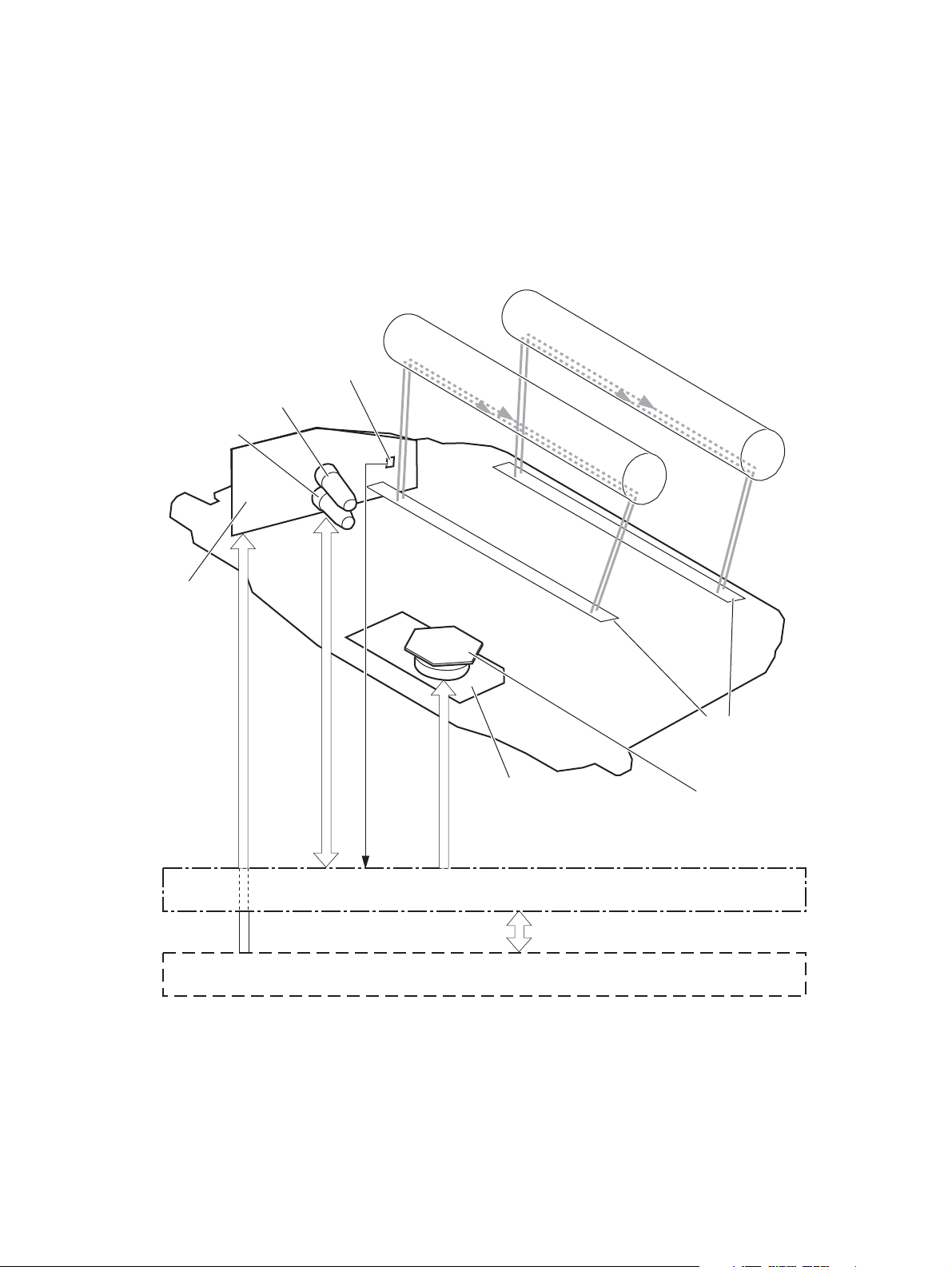
Laser/scanner system
The laser/scanner system forms the latent electrostatic image on the photosensitive drums according to the
VIDEO signals sent from the formatter. The product has two laser/scanners: one for yellow and magenta and
the other for cyan and black.
The main components of the laser/scanner system are the laser unit and the scanner motor unit, which are
controlled by the signals sent from the DC controller.
Figure 1-9 Laser/scanner system
Photosensitive drum (Y)
BD sensor
Yellow laser
Magenta laser
Photosensitive drum (M)
Laser unit
VIDEO signal
Scanner motor unit
SCANNER MOTOR
LASER CONTROL signal
BDI signal
CONTROL signal
DC controller
Formatter
Protective glass
Scanner mirror
ENWW Laser/scanner system 23
Page 48

Laser/scanner failure
The DC controller determines that a laser/scanner has failed when any of the following conditions occurs:
●
Laser failure: The detected laser intensity does not match a specified value when the product
initializes.
●
Scanner motor startup failure: The scanner motor does not reach a specified rotation within a
specified period from when the laser scanner starts driving.
●
Scanner-motor abnormal rotation: When a specified BD interval is not detected during a print
operation, a BD error is determined. If the BD interval does not recover within a specified period after
the BD error occurs, the product determines a scanner motor abnormal rotation.
The laser/scanner system does not have a mechanical laser shutter. For safety reason, the product has a
interlock switch. The interlock switch is turned off to interrupt +5 V power supply to the laser/scanner
system, when the front or right door is open.
24 Chapter 1 Theory of operation ENWW
Page 49

Protective-glass cleaners
Each laser/scanner has two openings that allow the laser beam to pass to the surface of the photosensitive
drum. These openings are covered by protective glass. When the protective glass gets dirty (for example, by
paper dust or toner) a protective-glass cleaner (PGC) cleans them.
NOTE: When a glass is dirty, streaks appear on the printed page in the process direction.
The PGC is a cleaning pad that slides along the laser shutter. With the front door open, the laser shutter is
positioned over the glass. As a toner cartridge is inserted, the cleaning pad is pushed down and wipes the
glass. When the front door is closed after cartridge insertion, the laser shutter (and PGC) move away from the
glass that allows the laser beam to pass through the glass.
When the front door is opened, the laser shutter and PGC move back into position over the glass. When the
cartridge is pulled out, the cleaning pad is returned to its starting position at the front of the cartridge
opening.
Figure 1-10 Protective-glass cleaners (PGCs)
ENWW Laser/scanner system 25
Page 50

Image-formation system
The image-formation system creates the printed image on the paper. The system consists of the following
components:
●
Toner cartridges
●
ITB
●
Secondary transfer roller
●
Fuser
●
Laser/scanner units
The DC controller controls the laser scanner unit and each of the high-voltage power supplies to form the
toner image on the photosensitive drum surface, according to the VIDEO signals. The toner image is then
transferred to the print-media and fused.
Figure 1-11 Image-formation system
High-voltage power supply T
Laser scanner unit
ITB
Laser scanner unit
High-voltage power supply D
Fuser
Secondary
transfer roller
DC controller
Print cartridge
26 Chapter 1 Theory of operation ENWW
Page 51

Figure 1-12 Image-formation drive system
Primary
charging
roller
Developing
roller
Primary
charging
roller
Developing
roller
Primary
charging
roller
Developing
roller
Fuser motor
M2
Primary
charging
roller
Developing
roller
M3
Y drum motor
M4
M drum motor
M5
C drum motor
M6
Bk drum motor
M1
ITB motor
ENWW Image-formation system 27
Page 52

Image formation process
The image-formation system consists of ten steps divided into six functional blocks.
Figure 1-13 Image-formation process
High-voltage power supply T
DC controller
Laser scanner unit
Table 1-13 Image formation process
ITB
Laser scanner unit
High-voltage power supply D
Fusing unit
Secondary
transfer roller
Cartridge
Functional block Steps Description
Latent image formation 1. Pre-exposure
2. Primary charging
3. Laser-beam exposure
Development 4. Development Toner adheres to the electrostatic latent image on the
Transfer 5. Primary transfer
6. Secondary transfer
7. Separation
Fusing 8. Fusing The toner fuses to the paper to make a permanent
ITB cleaning 9. ITB cleaning Residual toner is removed from the ITB.
Drum cleaning 10. Drum cleaning Residual toner is removed from the photosensitive
An invisible latent image forms on the surface of the
photosensitive drums.
photosensitive drums.
The toner image transfers to the ITB and later to the
paper.
image.
drums.
28 Chapter 1 Theory of operation ENWW
Page 53

Step 1: Pre-exposure
Light from the pre-exposure LED strikes the surface of the photosensitive drum to remove any residual
electrical charges from the drum surface.
Figure 1-14 Pre-exposure
Photosensitive drum
Step 2: Primary charging
The primary-charging roller contacts the photosensitive drum and charges the drum with negative potential.
Figure 1-15 Primary charging
Primary charging roller
LED
Photosensitive drum
Primary charging bias
ENWW Image-formation system 29
Page 54

Step 3: Laser-beam exposure
The laser beam strikes the surface of the photosensitive drum in the areas where the image will form. The
negative charge neutralizes in those areas, which are then ready to accept toner.
Figure 1-16 Laser-beam exposure
Step 4: Development
Toner acquires a negative charge as the developing cylinder contacts the developing blade. Because the
negatively charged surface of the photosensitive drums have been neutralized where they have been struck
by the laser beam, the toner adheres to those areas on the drums. The latent image becomes visible on the
surface of each drum.
Laser beam
Figure 1-17 Development
Developing blade
Developing roller
Developing bias
Photosensitive drum
30 Chapter 1 Theory of operation ENWW
Page 55

Step 5: Primary transfer
The positively charged primary-transfer rollers contact the ITB, giving the ITB a positive charge. The ITB
attracts the negatively charged toner from the surface of each photosensitive drum, and the complete toner
image transfers onto the ITB.
Figure 1-18 Primary transfer
Primary transfer roller
ITB
Primary transfer bias
Photosensitive
drum
Step 6: Secondary transfer
The paper acquires a positive charge from the secondary-transfer roller, and so it attracts the negatively
charged toner from the surface of the ITB. The complete toner image transfers onto the paper.
Figure 1-19 Secondary transfer
Secondary transfer
opposed roller
Paper
Secondary transfer bias
ITB
Secondary transfer roller
ENWW Image-formation system 31
Page 56

Step 7: Separation
The stiffness of the paper causes it to separate from the ITB as the ITB bends. The static-charge eliminator
removes excess charge from the paper to make sure that the toner fuses correctly.
Figure 1-20 Separation
Paper
Step 8: Fusing
To create the permanent image, the paper passes through heated, pressurized rollers to melt the toner onto
the page.
Secondary transfer
opposed roller
ITB
Static charge
eliminator
Secondary transfer roller
Figure 1-21 Fusing
Fuser heater
Fuser sleeve
Toner
Paper
Pressure roller
32 Chapter 1 Theory of operation ENWW
Page 57

Step 9: ITB cleaning
The cleaning blade scrapes the residual toner off the surface of the ITB. The residual toner feed screw
deposits residual toner in the toner collection box.
Figure 1-22 ITB cleaning
Residual toner feed screw
Step 10: Drum cleaning
The cleaning blade scrapes the residual toner off the surface of the photosensitive drum, and toner is
deposited in the toner collection box in the cartridge.
Figure 1-23 Drum cleaning
Cleaning blade
ITB
Cleaning blade
CRG toner collection box
Photosensitive
drum
ENWW Image-formation system 33
Page 58

Toner cartridges
Each toner cartridge is filled with toner and consists of the following components:
●
Photosensitive drum
●
Developing unit
●
Developing roller
●
Primary-charging roller
The DC controller rotates the drum motor to drive the photosensitive drum, developing roller, and the
primary-charging roller.
Figure 1-24 Toner cartridge system
Developing
disengagement
motor
DC controller
M10
SR11:
Developing disengagement sensor
Developing unit
SR1/SR2/SR3/SR4:
Drum home position sensor
M3/M4/M5/M6:
Drum motor
Primary charging roller
Memory
tag
Developing roller
The DC controller rotates the drum motor to drive the photosensitive drum, developing unit, and primary
charging roller.
34 Chapter 1 Theory of operation ENWW
Page 59

Memory tag
The memory tag is a non-volatile memory chip that stores information about the usage for the toner
cartridge. The product reads and writes the data in the memory tag.
The DC controller determines a memory tag error and notifies the formatter when it fails to either read from
or write to the memory tag.
●
Cartridge presence detection: The DC controller detects the presence of the cartridges by monitoring
the memory tag. The DC controller notifies the formatter when a cartridge is missing or installed in the
incorrect slot.
●
Toner level detection: The DC controller detects the remaining toner in a cartridge by the optical
detection method and then notifies the formatter of the remaining toner level.
●
Cartridge life detection: The DC controller detects the cartridge life by monitoring the total operating
time or remaining toner level of the toner cartridge. The DC controller determines a cartridge end of life
and notifies the formatter when total operating time of the cartridge reaches a specified time or the
cartridge runs out of toner.
Developing unit engagement and disengagement control
The product can print in full-color mode or in black-only mode. To print in black-only mode, the product
disengages the developing rollers in the cyan, magenta, and yellow toner cartridges, which maximizes the
life of the cartridges.
Figure 1-25 Developing-roller engagement and disengagement control
DC controller
Developing
M10
disengagement
motor
Developing unit
SR11
Developing disengagement sensor
Photosensitive drum
Developing disengagement cam
Developing unit is disengaged
Developing unit is engaged
ENWW Image-formation system 35
Page 60

The developing-roller engagement and disengagement control operates as follows: When the product is
turned on and when each print job is completed, all four of the developing units are disengaged from the
photosensitive drums.
●
The drive of the developing disengagement motor rotates the developing disengagement cam.
●
As the cam rotates, the developing unit engages with or separates from the photosensitive drum.
When the print mode is full color, the developing units engage with the drums. When the print mode is blackonly, only the black developing units engages with the drum.
The DC controller determines a developing disengagement motor failure and notifies the formatter when it
does not detect a specified signal from the developing disengagement sensor during the developing unit
engagement and disengagement operation.
36 Chapter 1 Theory of operation ENWW
Page 61

Intermediate transfer belt (ITB) unit
The ITB unit accepts the toner images from the photosensitive drums and transfers the completed image to
the paper. The ITB unit has the following main components:
●
Intermediate transfer belt (ITB)
●
ITB-drive roller
●
Primary-transfer roller
●
ITB cleaner
The ITB motor drives the ITB drive roller, which rotates the ITB. The motion of the ITB causes the primary
transfer rollers to rotate. The ITB cleaner cleans the ITB surface.
Figure 1-26 ITB unit
ITB cleaner
DC controller
ITB
Primary transfer roller
Primary transfer roller engagement and disengagement control
The sequence of the primary-transfer roller engagement and disengagement control is as follows:
1. The fuser motor turns on the primary-transfer disengagement solenoid and rotates the primary-
transfer roller disengagement cam.
2. As the cam rotates, the Y/M/C primary-transfer roller slide plate or the Bk primary-transfer roller slide
plate moves to the right or left, which causes the primary-transfer roller to move up or down.
3. The ITB engages with or separates from the photosensitive drum depending on the movement of the
primary-transfer rollers.
Depending on the requirements of the print job, the primary-transfer rollers engage with the ITB so it can
receive toner from the photosensitive drums. The primary-transfer roller has three engagement states.
ITB drive roller
M1
ITB motor
ENWW Image-formation system 37
Page 62

Table 1-14 Primary-transfer roller engagement states
All rollers disengaged The ITB is disengaged from all the four photosensitive drums. This state is the home
position for the ITB unit.
All rollers engaged The ITB is engaged with all four photosensitive drums. The state for full-color printing.
Black roller engaged The ITB is engaged with only the black photosensitive drum. The state for black-color
mode printing.
The DC controller determines a primary-transfer roller disengagement failure and notifies the formatter
when it does not detect a signal from the primary-transfer disengagement sensor even though the primarytransfer disengagement solenoid is turned on.
If the DC controller does not receive the expected signal from the ITB home-position sensor when the
primary-transfer roller engages or disengages, but the primary-transfer roller disengagement motor is
rotating, the DC controller determines that the primary-transfer-disengagement mechanism has failed, and
notifies the formatter.
The DC controller detects whether the ITB unit is new by monitoring the new ITB unit sensor. The DC
controller determines the ITB unit is at end of life and notifies the formatter when a specified number of
pages are printed after the ITB unit is replaced. If swapping ITB units between two products for
troubleshooting purposes, be sure to return the ITB units to their original products to maintain the correct
life count.
NOTE: A new ITB has a flag that causes the ITB life counter to be reset. When an ITB is installed in the
product, it cannot be removed and used again as a new ITB.
The DC controller detects the presence of an ITB unit by monitoring the primary-transfer roller
disengagement sensor. The DC controller turns on the primary-transfer disengagement solenoid for
specified times during an initial rotation period when the following events occur:
●
The product is turned on
●
The product exits sleep mode
●
The door is closed
The DC controller determines the absences of an ITB unit and notifies the formatter when it does not detect a
specified signal from the new primary transfer-roller disengagement sensor.
38 Chapter 1 Theory of operation ENWW
Page 63

Figure 1-27 Three states of primary-transfer roller engagement and disengagement
DC controller
Fuser motor
M2
SL1
Primary transfer
disengagement solenoid
<All colors are disengaged>
Photosensitive drum
<All colors are engaged>
ITB
SR9:
Primary transfer
disengagement sensor
Primary transfer roller
Primary transfer roller disengagement cam
YMC primary transfer roller slide plate
<Only black is engaged>
Bk primary transfer roller slide plate
ENWW Image-formation system 39
Page 64
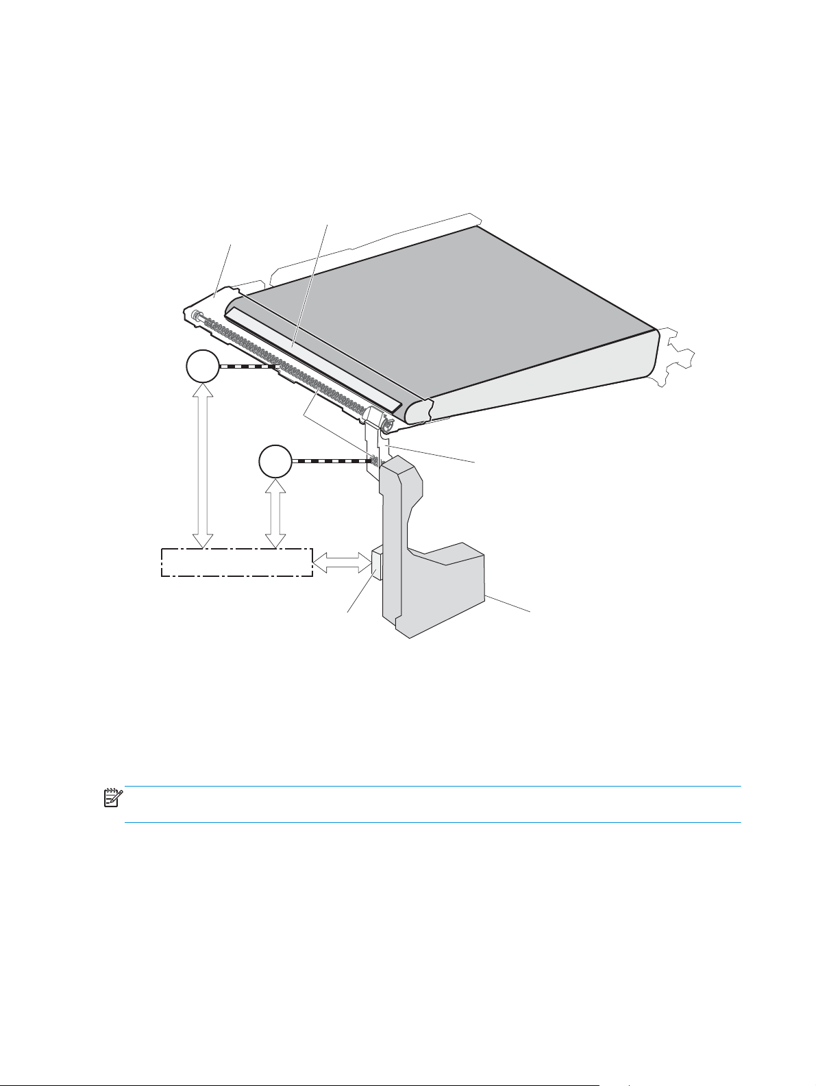
ITB cleaning mechanism
The cleaning blade in the ITB cleaner scrapes the residual toner off the ITB surface. The residual toner feed
screw deposits the residual toner to the residual toner feed unit. The ITB motor and the residual toner feed
motor drive the screw. The DC control detects whether the toner collection box is full, using the residualtoner full sensor, and then notifies the formatter.
Figure 1-28 ITB cleaning process
ITB cleaner
Cleaning blade
ITB motor
Calibration
The product calibrates itself to maintain excellent print quality. Calibration corrects color-misregistration and
color-density variation.
During calibration, the product places a specific pattern of toner on the surface of the ITB. Sensors at the end
of the ITB read the toner pattern to determine if adjustments are necessary.
M1
Residual toner
feed screw
M12
Residual toner
feed motor
DC controller
Residual toner full sensor
ITB
Residual toner feed unit
Toner collection box
NOTE: The product performs a drum-speed adjustment (DSA) during the full calibration operation. The DSA
compensates for variations between each drum and the speed of the ITB surface.
40 Chapter 1 Theory of operation ENWW
Page 65

Color-misregistration control
Internal variations in the laser/scanners can cause the toner images to become misaligned. The colormisregistration control corrects the following problems:
●
Horizontal scanning start position
●
Horizontal scanning magnification
●
Vertical scanning start position
The DC controller forms a pattern of toner on the surface of the ITB and measures a misaligned length with
the RD sensor.
Figure 1-29 Toner patterns for calibration
RD sensor
ITB
Pattern of toner
The DC controller signals the formatter to perform the color-misregistration control when one of the
following events occur:
●
A cartridge or the ITB is replaced.
●
A specified number of pages have printed.
●
The formatter sends a command.
The DC controller determines an RD sensor failure and notifies the formatter if it detects data from the RD
sensor that is not in a specified range, when the product is turned on or when the color-misregistration
control starts.
ENWW Image-formation system 41
Page 66

Image stabilization control
NOTE: The product contains a thermal sensor, located within the TCU level detection sensor, which
monitors the temperature in the cartridge area and uses this information to make adjustments during CPR
control.
Environmental changes or deterioration of the photosensitive drums and toner can cause variations in the
image density. The image-stabilization control reduces these fluctuations.
Table 1-15 Image-stabilization controls
Image density control (DMAX) This control corrects variations in image density related to deterioration of the
photosensitive drum or the toner. The DC controller adjusts the high-voltage biases to
correct the problem under the following conditions:
The image-stabilization control calibrates each high-voltage bias to stabilize the
fluctuations in image density caused by deterioration of the photosensitive drums or
toner or because of environmental changes. The DC controller determines the product's
environment based on the surrounding temperature and humidity data from the
environment sensor. The DC controller calibrates the biases according to the detected
environment and usage condition of the toner cartridge to obtain an appropriate image.
The DC controller determines an environment sensor failure and notifies the formatter
when it detects environmental data from the environment sensor with out of specified
value. The DC controller commands the formatter to control the image density under the
following conditions
●
The temperature of the main thermistor is too low when the product is turned on
●
A toner cartridge or the ITB is replaced
●
A specified number of pages have printed
●
After a specific period of the completion of a previous DMAX
●
The environment changes for a specified condition after a previous DMAX
Image halftone control (DHALF) The formatter performs this control to calibrate the halftone, based on the halftone-
density measurements, under the following conditions:
●
The formatter sends a command
●
DMAX is completed
The DC controller determines an RD sensor failure and notifies the formatter if it detects
data from the RD sensor out of a specified range.
The DC controller determines a RD sensor failure and notifies the formatter if it detects an out-of-specifieddata value from the RD sensor when the product is turned on or when the color misregistration control starts.
42 Chapter 1 Theory of operation ENWW
Page 67

Pickup, feed, and delivery system
The pickup, feed, and delivery system uses a series of rollers to move the paper through the product.
Figure 1-30 Paper path
Simplex media path
Duplex media path
Cassette pickup roller
Duplex reverse roller
Pressure roller
Fusing sleeve
Secondary transfer roller
MP tray pickup roller
Cassette feed roller
MP tray separation pad
Cassette separation roller
ENWW Pickup, feed, and delivery system 43
Page 68

Figure 1-31 Switches and sensors for the pickup, feed, and delivery system (M651 only)
SR6
SR5
SR14
SR15
SR22
SR20
SR26
SR25
SW4
Figure 1-32 Switches and sensors for the pickup, feed, and delivery system (M680 only)
SR101
SR103
Media sensor
SR8
SR23
SR24
SR5
SR14
SR15
Media sensor
SR22
SR20
SR26
SR8
SR25
SW4
SR23
SR24
44 Chapter 1 Theory of operation ENWW
Page 69

Table 1-16 Switches and sensors for the pickup, feed, and delivery system
Abbreviation Component
SW4 Cassette media size switch
SR5 Fuser delivery sensor
SR6 Face-down tray media-full sensor (M651 only)
SR8 MP tray media-presence sensor
SR14 Loop sensor 1
SR15 Loop sensor 2
SR20 Top of page (TOP) sensor
SR22 Duplex re-pickup sensor
SR23 Cassette media-surface sensor 1
SR24 Cassette media-surface sensor 2
SR25 Cassette media-presence sensor
SR26 Pre-registration media-feed sensor
SR101 IPTU media-full sensor (M680 only)
SR103 IPTU media-feed sensor (M680 only)
Media sensor
ENWW Pickup, feed, and delivery system 45
Page 70

Figure 1-33 Motors and solenoids for the pickup, feed, and delivery system
M14
M2 M11
SL2
Duplex flapper
M1
Pickup arm
SL4
Lifter
M7
M13
Table 1-17 Motors and solenoids for the pickup, feed, and delivery system
Abbreviation Component
M1 ITB motor
M2 Fuser motor
M7 Lifter motor
M11 Duplex reverse motor
M13 Pickup motor
M14 IPTU feed motor
CL1 Duplex re-pickup clutch
SL2 Duplex reverse solenoid
SL3 Multipurpose tray pickup solenoid
SL4 Cassette pickup solenoid
CL1
SL3
CL1 Duplex re-pick clutch
46 Chapter 1 Theory of operation ENWW
Page 71

The pickup, feed, and delivery system is divided into the following three blocks:
●
Pickup-and-feed block: From each pickup source to the fuser inlet
●
Fuser-and-delivery block: From the fuser to the delivery destination
●
Duplex block: From the duplex reverse unit to duplex re-pickup unit (for duplex models only)
Figure 1-34 Three main units of the pickup, feed, and delivery system
Fusing-and-delivery block
Duplex block
Pickup-and-feed block
ENWW Pickup, feed, and delivery system 47
Page 72

Pickup-and-feed unit
The pickup-and-feed unit picks an individual sheet of paper from the multipurpose tray or the cassettes,
carries it through the secondary-transfer unit, and feeds it into the fuser.
Figure 1-35 Pickup-and-feed unit
Simplex media path
Duplex media path
Pickup-and-feed block
Cassette pickup
Following are the sequence of steps for the cassette-tray pickup operation.
NOTE: Tray 1 and Tray 2 are optimal for paper pickup when using special paper or media other than 20lb
plain paper. For Tray 1 and Tray 2 the product increases the number of attempts to pickup a page, which
increases the reliability of successfully picking the page from the tray and decreases the possibility of a mispick jam.
HP recommends using Tray 1 or Tray 2 if the product is experiencing excessive or reoccurring jams from trays
other than Tray 1 and Tray 2, or for print jobs that require media other than 20lb plain paper.
1. The product is turned on or the cassette is inserted.
2. The cassette lift-up operation raises the lifting plate so paper can be picked up.
3. The pickup motor rotates when a print command is received from the formatter.
48 Chapter 1 Theory of operation ENWW
Page 73

4. The cassette pickup roller, cassette feed roller, and cassette separation roller rotate.
5. The cassette pickup solenoid turns on at a specified time.
6. The cassette pickup cam rotates.
7. As the pickup arm lowers, the cassette pickup roller touches the surface of the paper stack.
8. One sheet of paper feeds into the product.
Figure 1-36 Cassette-pickup mechanism
DC controller
Cassette pickup cam
Cassette pickup solenoid
Cassette-presence detection
The product detects the size of the paper loaded in the cassette and the presence of the cassette by
monitoring the cassette media size switch. The DC controller notifies the formatter when it determines the
absence of the cassette.
Pickup motor
Cassette feed roller
Cassette pickup roller
SL1
Pickup arm
M13
Cassette pickup solenoid
Cassette separation roller
Cassette feed roller
Pickup arm
Cassette pickup roller
Cassette separation roller
Table 1-18 Cassette-presence detection
Paper size Cassette media size switch
Top switch Center switch Bottom switch
UniversalONONON
A5 OFF OFF ON
B5 OFF ON ON
Executive ON OFF ON
Letter OFF ON OFF
ENWW Pickup, feed, and delivery system 49
Page 74

Table 1-18 Cassette-presence detection (continued)
Paper size Cassette media size switch
Top switch Center switch Bottom switch
A4
LegalONONOFF
Cassette absence OFF OFF OFF
ON OFF OFF
Cassette lift operation and cassette paper-presence detection
The product keeps the paper stack surface at the correct pickup position. The cassette lift-up operation is
performed under the following conditions:
●
The product is turned on
●
The cassette is inserted
●
The paper stack surface in the cassette lowers
Figure 1-37 Cassette lift mechanism
DC controller
SR23
Cassette media stack surface sensor 1
Cassette media stack surface sensor 2
SR24
Cassette media
Lifter motor
Lifting plate
presence sensor
M7
SR1
Cassette media stack surface sensor lever
Cassette media presence sensor lever
Lifter
The operational sequence of the cassette lift-up is as follows:
1. The lifter motor rotates and the lifter moves up.
2. When the cassette-media stack surface sensor 2 detects the stack surface of media, the lifter motor
stops.
3. The lifter motor rotates again to lift the lifter when the cassette-media stack surface sensor 1 detects
the stack surface and then lowers during printing.
When a cassette-media stack surface sensors does not detect the stack surface within a specified time period
after the lifter motor starts rotating, the DC controller determines a lifter motor failure and notifies the
formatter.
50 Chapter 1 Theory of operation ENWW
Page 75

Cassette multiple-feed prevention
In the cassette, a separation roller prevents multiple sheets of paper from entering the paper path. The
cassette pickup roller drives the separation roller through a sheet of paper.
The rotation of the cassette feed roller through the sheet drives the cassette separation roller. Because it is
equipped with a torque limiter, only one sheet is fed into the product.
The low friction force between the sheets weakens the driving force from the cassette feed roller. Therefore,
the separation roller is driven by its own driving force and holds back any multiple-fed sheets from the
cassette.
Figure 1-38 Multiple-feed prevention
Cassette pickup roller
Print-media
Cassette feed roller
Cassette separation roller
follows the cassette feed roller
Driving force from
the pickup motor
Cassette separation roller
Normal-feed
Multiple-feed
Multipurpose tray pickup
The product picks up one sheet of paper from the multipurpose (MP) tray.
Following are the sequence of steps for the multipurpose tray pickup operation.
NOTE: Tray 1 and Tray 2 are optimal for paper pickup when using special paper or media other than 20lb
plain paper. For Tray 1 and Tray 2 the product increases the number of attempts to pickup a page, which
increases the reliability of successfully picking the page from the tray and decreases the possibility of a mispick jam.
HP recommends using Tray 1 or Tray 2 if the product is experiencing excessive or reoccurring jams from trays
other than Tray 1 and Tray 2, or for print jobs that require media other than 20lb plain paper.
ENWW Pickup, feed, and delivery system 51
Page 76

1. The pickup motor reverses when a print command is received from the formatter.
2. When the DC controller turns on the MP tray pickup solenoid, the MP tray pickup roller rotates and the
lifting plate lifts.
3. As the lifting plate rises, the paper is picked up.
4. The multipurpose tray separation pad removes any multiple-fed sheets, and one sheet is fed into the
product.
The MP-tray media-presence sensor (SR8) detects whether paper is present in the MP tray.
Figure 1-39 Multipurpose tray pickup mechanism
DC controller
Paper feed
After the pickup operation, the paper feeds through the product and into the fuser.
Pickup motor
MP tray pickup solenoid
MP tray pickup roller
MP tray separation pad
M13
SL2
MP tray media presence sensor
SR8
Lifting plate
1. The paper picked up from the cassette is fed to the registration unit as the pickup motor rotates. The
paper picked up from the multipurpose tray is fed to the registration unit as the pickup motor rotates.
The duplex model has the duplex feed clutch. The driving force of the pickup motor is transmitted to the
duplex re-pickup roller by turning on the clutch.
2. The registration shutter corrects the skew-feed.
3. When the TOP sensor detects the leading edge of paper, the DC controller stops the paper so that the
media sensor detects the type of paper.
4. The DC controller controls the rotational speed of the pickup motor to align the paper with the leading
edge of the toner image on the ITB.
52 Chapter 1 Theory of operation ENWW
Page 77

5. The ITB motor rotates the ITB.
6. The toner image on the ITB is transferred onto the paper, and the paper is fed to the fuser.
The DC controller notifies the formatter of a paper size mismatch error when the paper length detected by
the TOP sensor does not match the paper size specified by the formatter.
Figure 1-40 Paper-feed mechanism
DC controller
ITB
M1
Pickup motor
M13
TOP sensor
SR20
Duplex re-pickup clutch
CL1
Media sensor
Registration shutter
Duplex re-pickup roller
Registration front feed roller
ITB motor
ENWW Pickup, feed, and delivery system 53
Page 78

Skew-feed prevention
The product can straighten the paper without slowing the feed operation.
1. The leading edge of paper strikes the registration shutter, and the leading edge is aligned with the
shutter.
2. As the feed rollers keep pushing the paper, the paper warps.
3. When the force is great enough, the registration shutter opens, and the paper passes through and
straightens.
Figure 1-41 Skew-feed prevention
Registration shutter
Registration shutter
Paper
Paper
54 Chapter 1 Theory of operation ENWW
Page 79

Paper detection
The product detects the type of paper by monitoring the media sensor. The media sensor detects the
glossiness of paper by the reflected light and the thickness of paper by transmitted light. The DC controller
identifies the type of media (for example, plain paper, light paper, heavy paper, glossy paper, glossy film, or
overhead transparency) and switches to the correct print mode. The DC controller determines a media
mismatch error and notifies the formatter under the following condition:
Simplex printing
●
●
Duplex printing
●
The DC controller flashes the media sensor during the initial rotation period under the following conditions:
●
●
When the light intensity is not a specified value, the DC controller determines a media-sensor failure and
notifies the formatter.
The specified print mode is overhead transparency (OHT), but the media sensor detects another paper
type.
The specified print mode is not auto or OHT, but the media sensor detects OHT.
The media sensor detects OHT.
The product is turned on
The product exits Sleep mode
Feed speed control
The DC controller adjusts the feed speed to improve the print quality depending on the paper type. The paper
is fed at a specified speed according to the print mode designated by the formatter.
Table 1-19 Print mode and feed speed
Print mode Feed speed Media sensor detection
Normal 1/1 Yes
Heavy media 1 3/4 No
Heavy media 2 1/2 Yes
Heavy media 3 1/3 Yes
Light media 1 1/1 Yes
Light media 2 1/1 Yes
Glossy media 1 1/3 Yes
Glossy media 2 1/3 Yes
Glossy media 3 1/4 Yes
Glossy film 1/4 Yes
Envelope 1 1/2 No
OHT 1/4 Yes
ENWW Pickup, feed, and delivery system 55
Page 80

Table 1-19 Print mode and feed speed (continued)
Print mode Feed speed Media sensor detection
Label 1/2 No
Designated media 1 1/2 No
Fusing and delivery block
The fusing and delivery unit fuses the toner onto the paper and delivers the printed page into the output bin.
The following controls ensure optimum print quality:
The face-down tray media full sensor on the output bin detects whether the tray is full of printed pages. The
DC controller notifies the formatter when the sensor is on for a specified time.
Figure 1-42 Fuser and delivery unit
Simplex media path
Duplex media path
IPTU media full sensor
SR101
Fusing-and-delivery block
56 Chapter 1 Theory of operation ENWW
Page 81

Loop control
The loop control stabilizes the paper feed operation before the paper enters the fuser. If the pressure roller
rotates slower than the secondary transfer roller, the paper loop increases and an image defect or paper
crease occurs. If the pressure roller rotates faster than the secondary transfer roller, the paper loop
decreases and a vertical scanning magnification failure occurs because the pressure roller pulls the paper.
To prevent these problems, loop sensor 1 and loop sensor 2 detect the paper loop before the paper enters
the fuser. The DC controller adjusts the rotational speed of the fuser motor according to the output signals
from the loop sensors and maintains the paper loop. Loop sensor 1 is for light media, and loop sensor 2 is for
heavy media. The DC controller slows the fuser motor when the sensor is off and speeds up the sensor when
the sensor is on.
Figure 1-43 Loop-control mechanism
Pressure roller
Sensor flag
Pressure roller
ITB
Secondary transfer rollerr
The pressure roller rotates faster
than the secondary transfer roller
SR15: Loop sensor 2
SR14: Loop sensor 1
Loop sensor 1,2
Sensor flag
For heavy media
For light media
Sensor flag
The pressure roller rotates slower
than the secondary transfer roller
Loop sensor: OFF
Loop sensor: ON
ENWW Pickup, feed, and delivery system 57
Page 82

Pressure roller pressurization and depressurization control
To prevent excessive wear on the pressure roller and help with jam-clearing procedures, the pressure roller
pressurizes only during printing and standby. The DC controller reverses the fuser motor. The fuser motor
rotates the fuser pressure-release cam.
Figure 1-44 Pressure-roller pressurization control
DC controller
Fuser motor
M2
SR7 SR7
Fuser pressure release cam
Pressure roller
Fuser sleeve
Pressurized Depressurized
The pressure roller depressurizes under the following conditions:
●
The product is turned off
●
Any failure occurs
●
During power-save mode
●
When a paper jam is detected
If the DC controller does not sense the fuser pressure-release sensor for a specified period after it reverses
the fuser motor, it notifies the formatter that a fuser pressure-release mechanism failure has occurred.
58 Chapter 1 Theory of operation ENWW
Page 83

Duplex Block
The duplexing unit reverses the paper and feeds it through the paper path to print the second side.
Figure 1-45 Duplexing unit
Simplex media path
Duplex media path
Duplex block
ENWW Pickup, feed, and delivery system 59
Page 84

Duplex reverse and duplex feed control
The duplex reverse control reverses the paper after the first side is printed and feeds it to the duplex repickup position to print the second side of the page.
1. At a specified time after the first side of a page is printed, the duplex reverse motor rotates, and the
duplex reverse solenoid is turned on.
2. The duplex flapper moves, and the paper is fed to the duplex reverse unit.
3. After a specified period of time, the duplex reverse motor is reversed, and the paper is fed to the duplex
feed unit.
4. The duplex reverse motor and the pickup motor move the paper to the duplex re-pickup position.
5. The duplex reverse motor and the duplex feed clutch stop, and the paper feed operation pauses.
6. After a specified period of time, the duplex reverse motor rotates, and the duplex feed clutch is turned
on. The paper is then picked up again.
Figure 1-46 Duplex reverse and feed control
Duplex reverse unit
M11
Duplex flapper
Duplex reverse
solenoid
Duplex re-pickup
clutch
Duplex re-pickup position
SL2
Duplex feed unit
Duplex reverse motor
Pickup motor
CL1
M13
Simplex media path
Duplex media path
60 Chapter 1 Theory of operation ENWW
Page 85

Duplex operation
The product has the following two duplex-media-feed modes depending on the paper sizes:
●
One-sheet mode: Prints one sheet that is printed on two sides in one duplex print operation
●
Two-sheet mode: Prints two sheets that are printed on two-sides in one duplex print operation
Table 1-20 Paper sizes
Paper size Duplex media feed mode
A4 One-sheet operation
Letter
B5
Executive
Legal One-sheet operation
Two-sheet operation
The formatter specifies the duplex-media-feed mode for each two-sided print job. Duplex printable paper
size (A4, Letter, B5, Legal and Executive) and designated print mode (Auto, Normal, Heavy media 1, Heavy
media 2 [120 g/m
2
or lighter], Glossy media 1, Glossy media 2, Glossy media 3, Glossy film, Designated media
1, and Designated media 2) must be specified.
ENWW Pickup, feed, and delivery system 61
Page 86

Jam detection
The product uses the following sensors to detect the paper as it moves through the paper path and to report
to the DC controller if the paper has jammed.
●
Fuser delivery sensor (SR5)
●
Top of page (TOP) sensor (SR20)
●
Loop sensor 1 (SR14)
●
Loop sensor 2 (SR15)
●
Duplex re-pickup sensor (SR22)
●
IPTU media full sensor (SR101)
NOTE: SR101 sensor is not used on products that have a stapling mailbox is installed.
●
IPTU media feed sensor (SR103)
Figure 1-47 Jam detection sensors
Simplex media path
Duplex media path
SR101
SR103
SR20
SR5
SR14
SR15
SR22
The product determines that a jam has occurred if one of these sensors detects paper at an inappropriate
time. The DC controller stops the print operation and notifies the formatter.
62 Chapter 1 Theory of operation ENWW
Page 87

Table 1-21 Jams that the product detects
Jam Description
Pickup delay jam The TOP sensor does not detect the leading edge of the paper within a specified time (including two
retries) after the pickup operation from the cassette, multipurpose tray, or optional paper feeder
starts.
Pickup stationary jam The TOP sensor does not detect the trailing edge of the paper within a specified time from when it
detects the leading edge.
Fuser delivery delay jam The fuser delivery sensor does not detect the leading edge of the paper within a specified period
after the TOP sensor detects the leading edge.
Fuser delivery stationary jam The fuser delivery sensor does not detect the trailing edge of the paper within a specified period
after it detects the leading edge.
Wrapping jam After detecting the leading edge of the paper, the fuser delivery sensor detects the absence of
paper, and it has not yet detected the trailing edge.
Residual paper jam One of the following sensors detects paper presence during the initialization sequence:
●
Fuser delivery sensor
●
Loop sensor 1
●
Loop sensor 2
One of the following sensors detects paper presence during the an automatic delivery operation:
●
Fuser delivery sensor
●
TOP sensor
●
Loop sensor 1
●
Loop sensor 2
●
Duplex re-pickup sensor
●
IPTU media feed sensor
Door open jam A door is open while paper is moving through the product.
Duplexing re-pickup jam 1 The duplex re-pickup sensor does not detect the leading edge of the paper within a specified period
after the media reverse operation starts in the duplex reverse unit.
Duplexing re-pickup jam 2 The TOP sensor does not detect the leading edge of the paper within a specified period after the
paper is re-picked.
IPTU delivery delay jam 1 The IPTU media feed sensor does not detect the leading edge of paper within a specified time period
after the fusing delivery sensor detects the leading edge.
IPTU delivery delay jam 2 The IPTU media full sensor does not detect the leading edge of paper within a specified period after
the IPTU media feed sensor detects the leading edge.
IPTU delivery stationary jam 1 The IPTU media feed sensor does not detect the trailing edge of paper within a specified period after
it detects the leading edge.
IPTU delivery stationary jam 2 The IPTU media feed sensor detects a paper absence yet it does not detect the trailing edge of
paper after it detects the leading edge.
Automatic delivery: The product automatically clears paper if the TOP sensor, duplex re-pickup sensor, IPTU
media feed sensor, or PD media feed sensors detect residual paper during initialization.
ENWW Pickup, feed, and delivery system 63
Page 88

Optional paper feeders
Three types of optional paper feeders are available for the product:
●
1 x 500 sheet paper feeder
●
1 x 500 sheet paper feeder with cabinet
●
2,500-sheet paper feeder high-capacity input (HCI)
The operational sequence of the paper feeders is controlled by the paper feeder controller.
Figure 1-48 1 x 500 optional paper feeder
PD feed roller
PD pickup roller
PD separation roller
64 Chapter 1 Theory of operation ENWW
Page 89

Figure 1-49 Signals for the paper feeder
Paper deck
Motor
+3.3V
Solenoid
DC controller
+24V
Paper deck
controller
Photointerrupter
Switch
The input trays contain several motors, solenoids, sensors, and switches, as described in the following table.
Table 1-22 Electrical components for the paper feeder
Component type Abbreviation Component name
Motors M1 PD lifter motor 1
M2 PD pickup motor
Solenoids SL1 PD pickup solenoid 1
Sensors SR1 Tray 3 paper surface sensor 1
SR2 Tray 3 paper surface sensor 2
SR3 Tray 3 paper present presence sensor
SR4 Tray 3 feed sensor
Switches SW1 PD right door switch
ENWW Optional paper feeders 65
Page 90

Figure 1-50 2,500-sheet paper feeder HCI
66 Chapter 1 Theory of operation ENWW
Page 91

Figure 1-51 Signals for 2,500-sheet paper feeder HCI
2,500-sheet paper deck
+3.3VS
Motor
+24VA
Solenoid
DC controller HCI controller
Photointerrupter
Switch
The input trays contain several motors, solenoids, sensors, and switches, as described in the following table.
Table 1-23 Electrical components for the 2,500-sheet paper feeder HCI
Component type Abbreviation Component name
Motor M1 Cassette 1 (Tray 3) lifter motor
M2 Pickup motor
M3 Cassette 2 (Tray 4) lifter motor
M4 Cassette 3 (Tray 5) lifter motor
Solenoid SL1 Cassette 1 (Tray 3) pickup solenoid
SL2 Cassette 2 (Tray 4) pickup solenoid
SL3 Cassette 3 (Tray 5) pickup solenoid
Switch SW1 Right door open detection switch
SW2 Cassette 1 (Tray 3) media-size switch
SW3 Cassette 2 (Tray 4) media-size switch
SW4 Cassette 3 (Tray 5) media-size switch
Photointerrupter SR1 Cassette 1 (Tray 3) media-surface sensor 1
SR2 Cassette 1 (Tray 3) media-surface sensor 2
SR3 Cassette 1 (Tray 3) media-presence sensor
SR4 Cassette 1 (Tray 3) media-feed sensor
SR5 Cassette 2 (Tray 4) media-surface sensor 1
SR6 Cassette 2 (Tray 4) media-surface sensor 2
SR7 Cassette 2 (Tray 4) media-presence sensor
SR8 Cassette 2 (Tray 4) media-feed sensor
SR9 Cassette 3 (Tray 5) media-surface sensor 1
SR10 Cassette 3 (Tray 5) media-surface sensor 2
SR11 Cassette 3 (Tray 5) media-presence sensor
SR12 Cassette 3 (Tray 5) media-feed sensor
ENWW Optional paper feeders 67
Page 92

Motor control
The 1x500-sheet paper feeder has two motors for feeding paper.
Table 1-24 Motor control (1x500-sheet paper feeder)
Component Drives Failure
M1 PD lifter motor 1 Lifter of the upper cassette No
M2 PD pickup motor PD pickup roller, PD feed roller, and PD separation roller No
detection
The 2,500-sheet paper feeder HCI has four motors for the paper-feed and cassette lift-up. The HCI signals a
jam when the pickup motor fails.
Table 1-25 Motor control (2,500-sheet paper feeder HCI)
Component Drives Failure
detective
M1 Cassette 1 (Tray 3) lifter motor Lifter for cassette 1 (Tray 3) No
M2 Pickup motor Pickup roller, separation roller and feed roller for
cassette 1 to 3 (Tray 3 to Tray 5)
M3 Cassette 2 (Tray 4) lifter motor Lifter for cassette 2 (Tray 4) Yes
M4 Cassette 3 (Tray 5) lifter motor Lifter for cassette 3 (Tray 5) Yes
Yes
68 Chapter 1 Theory of operation ENWW
Page 93

Paper-feeder pickup and feed operation
The paper feeder picks up one sheet from the paper-feeder cassette and feeds it to the product.
Figure 1-52 Paper-feeder pickup and feed operation (1x500-sheet paper feeder)
M2
SW2
Pickup arm
SR3
M1
SR4
SR2
SR1
SL1
Table 1-26 Pickup feed components (1x500-sheet paper feeder)
Abbreviation Component
M1 PD lifter motor 1
M2 PD pickup motor
SL1 PD pickup solenoid 1
SR1 Tray 3 paper surface sensor 1
SR2 Tray 3 paper surface sensor 2
SR3 Tray 3 paper presence sensor
SR4 Tray 3 paper present sensor
SW2 Tray 3 paper size switches
The 2,500-sheet paper feeder HCI has three cassettes. The cassette 1 (Tray 3) and cassette 2 (Tray 4) operate
in the same manner.
ENWW Optional paper feeders 69
Page 94

Figure 1-53 Paper-feeder pickup and feed operation (2,500-sheet paper feeder HCI)
SR4
Cassette 1
Cassette 2
Cassette 3
Lifting plate
SW2
SW3
SL1
SR1, SR2, SR3
M1
Lifter
SL2
SR5, SR6, SR7
M3
Lifter
SL3
Wire
M2
SR8
SR12
SR9
SR10
SR11
SW4
Tray
M4
Table 1-27 Pickup feed components (2,500-sheet paper feeder HCI)
Abbreviation Component name
M1 Cassette 1 (Tray 3) lifter motor
M2 Pickup motor
M3 Cassette 2 (Tray 4) lifter motor
M4 Cassette 3 (Tray 5) lifter motor
SL1 Cassette 1 (Tray 3) pickup solenoid
SL2 Cassette 2 (Tray 4) pickup solenoid
SL3 Cassette 3 (Tray 5) pickup solenoid
SW2 Cassette 1 (Tray 3) media-size switch
SW3 Cassette 2 (Tray 4) media-size switch
Pulley
SW4 Cassette 3 (Tray 5) media-size switch
70 Chapter 1 Theory of operation ENWW
Page 95

Table 1-27 Pickup feed components (2,500-sheet paper feeder HCI) (continued)
Abbreviation Component name
SR1 Cassette 1 (Tray 3) media-surface sensor 1
SR2 Cassette 1 (Tray 3) media-surface sensor 2
SR3 Cassette 1 (Tray 3) media-presence sensor
SR4 Cassette 1 (Tray 3) media-feed sensor
SR5 Cassette 2 (Tray 4) media-surface sensor 1
SR6 Cassette 2 (Tray 4) media-surface sensor 2
SR7 Cassette 2 (Tray 4) media-presence sensor
SR8 Cassette 2 (Tray 4) media-feed sensor
SR9 Cassette 3 (Tray 5) media-surface sensor 1
SR10 Cassette 3 (Tray 5) media-surface sensor 2
SR11 Cassette 3 (Tray 5) media-presence sensor
SR12 Cassette 3 (Tray 5) media-feed sensor
Paper-size detection and cassette-presence detection
The paper feeder detects the size of paper loaded in the paper feeder and the presence of the cassette using
the PD media size switch.
Table 1-28 Paper-size detection and cassette-presence detection (1 x 500 paper feeder)
Paper size Paper-feeder cassette media-size switch settings
Top switch Center switch Bottom switch
UniversalOnOnOn
A5 Off Off On
B5 Off On On
Executive On Off On
Letter Off On Off
A4 On Off Off
LegalOnOnOff
No cassette Off Off Off
The HCI controller detects the size of the paper loaded in the paper deck cassette and the presence of the
cassette by monitoring the cassette media-size switch. The cassette media-size switch contains three subswitches. The HCI controller detects the size of paper and the presence of cassette according to the
combination of the sub-switches and notifies the formatter through the DC controller. It detects only the
presence of cassette during Sleep mode.
ENWW Optional paper feeders 71
Page 96

Table 1-29 Paper-size detection and cassette-presence detection (2,500-sheet paper feeder HCI)
Paper size Cassette media-size switch SW2, SW3 Cassette media-size switch SW4
Top Center Bottom Top Center Bottom
Custom size On On On N/A N/A N/A
A5 On On Off N/A N/A N/A
B5 OffOnOnN/AN/AN/A
Executive On Off On N/A N/A N/A
Letter Off On Off Off On On
A4 On Off Off On Off On
Legal OnOnOffOffOffOn
Cassette absence Off Off Off Off Off Off
72 Chapter 1 Theory of operation ENWW
Page 97

Paper-feeder cassette lift operation
The paper feeder keeps the paper stack surface at the correct pickup position. The cassette lift operation
occurs under the following conditions:
●
The product is turned on.
●
The cassette is inserted.
●
The paper stack surface of the cassette lowers.
The sequence occurs as follows:
1. The PD lifter motor rotates and the lifter moves up.
2. When the tray media-stack-surface sensor detects the stack surface of the paper, the PD lifter motor
stops.
3. The PD lifter motor rotates again to lift the lifter when the PD cassette media-stack-surface sensor
detects the stack surface, and then lowers during printing.
If a tray media-stack-surface sensor does not detect a stack surface within a specified period after the PD
lifter motor starts rotating, the paper feeder driver determines that the PD lifter motor has failed and
through the DC controller notifies the formatter.
Figure 1-54 Paper-feeder cassette lift
PD cassette media stack surface sensor 1
SR1/SR5/SR12
PD cassette media stack surface sensor 2
SR2/SR8/SR9
PD cassette media presence sensor
SR3/SR6/SR11
PD cassette media stack surface sensor lever
Lifting plate
M1/M3/M4
PD lifter motor
M
Lifter
PD cassette media presence sensor lever
The paper-feeder driver notifies the formatter if either of the paper-feeder media-stack surface sensors fails
to detect the stack surface within a specified period from when a lift-up operation starts.
ENWW Optional paper feeders 73
Page 98

Paper feeder jam detection
The 1x500-sheet paper feeder uses the Tray 3 paper presence sensor (SR4) to detect the presence of paper
and to check whether paper has jammed.
Figure 1-55 Jam detection (1x500-sheet paper feeder)
SR4
The 1x500-sheet paper feeder detects the following jams:
●
1x500-sheet PD pickup delay jam: Tray 3 feed sensor does not detect the leading edge of paper within
a specified time (including two retries) after the pickup operation starts.
●
1x500-sheet PD pickup stationary jam: Tray 3 feed sensor does not detect the trailing edge of paper
within a specified time after the sensor detects the leading edge.
●
1x500-sheet PD residual paper jam: Tray 3 feed sensor detects the presence of paper for a specified
time during an automatic delivery operation.
The 2,500-sheet paper feeder HCI uses the following sensors to detect the presence of the paper and to
check whether the paper is being fed correctly or has jammed:
●
Cassette 1 (Tray 3) media-feed sensor (SR4)
●
Cassette 2 (Tray 4) media-feed sensor (SR8)
●
Cassette 3 (Tray 5) media-feed sensor (SR12)
74 Chapter 1 Theory of operation ENWW
Page 99

Figure 1-56 2,500-sheet paper feeder HCI media feed sensors
SR4
SR8
SR12
The 2,500-sheet paper feeder HCI detects the following jams.
●
No pick jam 1
◦
From cassette 1 (Tray 3): The cassette 1 (Tray 3) media-feed sensor does not detect the leading
edge of paper within a specified period from when the cassette 1 (Tray 3) pickup solenoid is turned
on.
◦
From cassette 2 (Tray 4): The cassette 2 (Tray 4) media-feed sensor does not detect the leading
edge of paper within a specified period from when the cassette 2 (Tray 4) pickup solenoid is turned
on.
◦
From cassette 3 (Tray 5): The cassette 3 (Tray 5) media-feed sensor does not detect the leading
edge of paper within a specified period from when the cassette 3 (Tray 5) pickup solenoid is turned
on.
●
No pick jam 3
ENWW Optional paper feeders 75
Page 100

◦
From cassette 2 (Tray 4): The cassette 1 (Tray 3) media-feed sensor does not detect the leading
edge of paper within a specified period from when the cassette 2 (Tray 4) media-feed sensor
detects the leading edge.
◦
From cassette 3 (Tray 5): The cassette 1 (Tray 3) media-feed sensor does not detect the leading
edge of paper within a specified period from when the cassette 3 (Tray 5) media-feed sensor
detects the leading edge.
●
Pickup stay jam 2
◦
From cassette 1 (Tray 3): The cassette 1 (Tray 3) media-feed sensor does not detect the trailing
edge of paper within a specified period from when it detects the leading edge.
◦
From cassette 2 (Tray 4): The cassette 2 (Tray 4) media-feed sensor does not detect the trailing
edge of paper within a specified period from when it detects the leading edge.
◦
From cassette 3 (Tray 5): The cassette 3 (Tray 5) media-feed sensor does not detect the trailing
edge of paper within a specified period from when it detects the leading edge.
●
Pickup stay jam 3
◦
From cassette 2 (Tray 4): The cassette 1 (Tray 3) media-feed sensor does not detect the trailing
edge of paper within a specified period from when it detects the leading edge.
◦
From cassette 3 (Tray 5): The cassette 1 (Tray 3) media-feed sensor does not detect the trailing
edge of paper within a specified period from when it detects the leading edge.
●
Residual paper jam: Any one of the following sensor detects a paper presence when the product is
turned on, when the door is closed or when the product exits power-save mode (Sleep mode, active
OFF, or inactive OFF).
◦
Cassette 1 (Tray 3) media-feed sensor
◦
Cassette 2 (Tray 4) media-feed sensor
◦
Cassette 3 (Tray 5) media-feed sensor
●
Right door open jam
◦
The right door open is detected during a paper feed operation.
76 Chapter 1 Theory of operation ENWW
 Loading...