

Page 1

LASERJET ENTERPRISE 600 M601, M602, AND
M603 SERIES PRINTER
Service Manual
Page 2

Page 3

HP LaserJet Enterprise 600 M601,
M602, and M603 Series Printer
Service Manual
Page 4

Copyright and License
Trademark Credits
© 2011 Copyright Hewlett-Packard
Development Company, L.P.
Reproduction, adaptation, or translation
without prior written permission is
prohibited, except as allowed under the
copyright laws.
The information contained herein is subject
to change without notice.
The only warranties for HP products and
services are set forth in the express warranty
statements accompanying such products and
services. Nothing herein should be
construed as constituting an additional
warranty. HP shall not be liable for technical
or editorial errors or omissions contained
herein.
Part number: CE988-90945
Edition 1, 11/2011
ENERGY STAR and the ENERGY STAR mark
are registered U.S. marks.
Page 5

Conventions used in this guide
TIP: Tips provide helpful hints or shortcuts.
NOTE: Notes provide important information to explain a concept or to complete a task.
CAUTION: Cautions indicate procedures that you should follow to avoid losing data or damaging
the product.
WARNING! Warnings alert you to specific procedures that you should follow to avoid personal
injury, catastrophic loss of data, or extensive damage to the product.
ENWW iii
Page 6

iv Conventions used in this guide ENWW
Page 7

Table of contents
1 Theory of operation .......................................................................................................... 1
Basic operation ........................................................................................................................ 2
Major print systems ................................................................................................... 2
Internal components .................................................................................................. 3
Operating sequence .................................................................................................. 7
Formatter system ...................................................................................................................... 8
Sleep mode .............................................................................................................. 8
Input/output ............................................................................................................. 8
USB .......................................................................................................... 8
Embedded print server ................................................................................ 9
Hard-disk .................................................................................................. 9
CPU ......................................................................................................... 9
Memory ................................................................................................................... 9
Random-access memory .............................................................................. 9
Nonvolatile memory ................................................................................... 9
DIMM slot ................................................................................................................ 9
PJL overview ........................................................................................................... 10
PML ....................................................................................................................... 10
Control panel ......................................................................................................... 10
Engine-control system .............................................................................................................. 11
DC controller PCA ................................................................................................... 12
Sensors, solenoids, and switches ............................................................................... 13
Motors and fans ...................................................................................................... 14
Failure detection ...................................................................................... 14
Motor failure ............................................................................ 14
Fan motor failure ....................................................................... 14
Engine power supply ................................................................................ 15
Fuser-control circuit .................................................................... 15
Low-voltage power supply .......................................................... 17
High-voltage power supply ......................................................... 18
Overcurrent/overvoltage protection ............................................. 19
Image-formation system ........................................................................................................... 20
ENWW v
Page 8

Image-formation process .......................................................................................... 21
Block 1: Latent image formation ................................................................. 23
Step 1: Primary charging ........................................................... 23
Step 2: Laser-beam exposure ...................................................... 23
Block 2: Developing ................................................................................. 24
Step 3: Developing .................................................................... 24
Block 3: Transfer ...................................................................................... 25
Step 4: Transfer ........................................................................ 25
Step 5: Separation .................................................................... 25
Block 4: Fusing ........................................................................................ 26
Step 6: Fusing ........................................................................... 26
Block 5: Drum cleaning ............................................................................. 27
Step 7: Drum cleaning ............................................................... 27
Step 8: Drum charge elimination ................................................. 27
Laser/scanner system ............................................................................................................. 28
Laser failure detection .............................................................................................. 30
Pickup, feed, and delivery system ............................................................................................. 31
Pickup-and-feed block .............................................................................................. 32
Fuser/delivery block ................................................................................................ 33
Pressure roller pressure release control ....................................................................... 33
Paper trays ............................................................................................................. 34
Printing from Tray 1 .................................................................................. 34
Printing from Tray 2 .................................................................................. 34
Cassette media size detection and cassette presence detection ...................... 34
Jam detection ......................................................................................................... 36
1x500-sheet paper feeder ....................................................................................................... 40
Pickup-and-feed operation (PF) .................................................................................. 41
Cassette lift operation (PF) ........................................................................................ 43
Cassette media size detection and cassette presence detection (PF) ............................... 43
Cassette multiple-feed prevention (PF) ........................................................................ 43
Jam detection (PF) ................................................................................................... 43
1x1500-sheet paper deck ....................................................................................................... 44
Pickup-and-feed operation (PD) ................................................................................. 45
Cassette lift operation (PD) ....................................................................................... 47
Media size detection (PD) ........................................................................................ 48
Multiple-feed prevention (PD) .................................................................................... 48
Jam detection (PF) ................................................................................................... 48
Envelope feeder ..................................................................................................................... 49
Pickup-and-feed operation (EF) .................................................................................. 50
Multiple-feed prevention (EF) ..................................................................................... 50
Multiple-feed detection (EF) ....................................................................................... 51
vi ENWW
Page 9

Jam detection (EF) ................................................................................................... 51
Duplexer ............................................................................................................................... 53
Motor and fan control (DP) ....................................................................................... 54
Failure detection (DP) ................................................................................ 55
Reverse-and-re-pickup operation (DP) ......................................................................... 55
Side registration adjustment operation (DP) ................................................................ 56
Jam detection (DP) ................................................................................................... 58
2 Removal and replacement .............................................................................................. 59
Introduction ........................................................................................................................... 60
Removal and replacement strategy ........................................................................................... 60
Electrostatic discharge ............................................................................................................ 60
Required tools ........................................................................................................................ 61
Types of screws ..................................................................................................................... 62
Service approach ................................................................................................................... 63
Before performing service ........................................................................................ 63
After performing service ........................................................................................... 63
Post-service test ....................................................................................................... 63
Print-quality test ........................................................................................ 63
Customer replaceable units (CRUs) ........................................................................................... 64
Print cartridge ......................................................................................................... 64
Tray 2 ................................................................................................................... 65
Tray 2 separation, pickup, and feed rollers ................................................................ 66
Transfer roller ........................................................................................................ 69
Fuser ..................................................................................................................... 70
Remove the fuser ...................................................................................... 70
Formatter cover and formatter cage ........................................................................... 71
Installing a new formatter .......................................................................... 73
Hard drive ............................................................................................................. 74
Remove the SSM ...................................................................................... 74
Remove the encrypted HHD ....................................................................... 76
Installing a replacement hard drive ............................................................. 78
SSM firmware upgrade .............................................................. 78
HDD firmware upgrade .............................................................. 79
Memory DIMM ....................................................................................................... 80
Remove the memory DIMM ....................................................................... 80
Install the memory DIMM ........................................................................... 81
Tray 1 pickup and feed rollers .................................................................................. 82
Tray 1 separation roller ........................................................................................... 85
Rear output bin ....................................................................................................... 87
Covers .................................................................................................................................. 88
ENWW vii
Page 10

Top-accessory cover ................................................................................................ 88
Envelope feed accessory covers ................................................................................ 89
Duplex accessory or cover ....................................................................................... 90
Tray 2 extension door .............................................................................................. 91
Remove the Tray 2 extension door .............................................................. 91
Top cover ............................................................................................................... 92
Remove the top cover ............................................................................... 92
Right-side cover ....................................................................................................... 95
Remove the right-side cover ....................................................................... 95
Reinstall the right cover ............................................................................. 97
Left-side cover ......................................................................................................... 98
Remove the left-side cover ......................................................................... 98
Right-front cover .................................................................................................... 100
Remove the right-front cover ..................................................................... 100
Rear-upper cover ................................................................................................... 103
Remove the rear-upper cover ................................................................... 103
Front cover ........................................................................................................... 105
Remove the front cover ............................................................................ 105
Main assemblies .................................................................................................................. 107
Registration assembly ............................................................................................ 107
Control-panel assembly .......................................................................................... 109
Remove the control-panel assembly ........................................................... 109
Walk-up USB port and cable .................................................................................. 111
Remove the walk-up USB port and cable ................................................... 111
Inner connecting PCA ............................................................................................ 114
Remove the inner connecting PCA ............................................................ 114
Reinstall the inner connecting PCA ........................................................... 116
Fan FN102 .......................................................................................................... 117
Remove fan FN102 ................................................................................ 117
Fan FN103 .......................................................................................................... 119
Remove fan FN103 ................................................................................ 119
Pickup-motor assembly (M101) ............................................................................... 121
Remove the pickup-motor assembly ........................................................... 121
Drum-motor assembly (M102) ................................................................................. 123
Remove the drum motor .......................................................................... 123
Lifter-motor assembly (M103) .................................................................................. 125
Remove the lifter motor ........................................................................... 125
DC controller PCA ................................................................................................. 128
Remove the DC controller PCA ................................................................. 128
Reinstallation tip ..................................................................................... 129
Installing a new formatter and a new DC controller .................................... 129
viii ENWW
Page 11

Pickup-drive assembly ............................................................................................ 131
Remove the pickup-drive assembly ............................................................ 131
Reinstall the pickup-drive assembly ........................................................... 136
Fuser-motor assembly (M299) ................................................................................. 137
Remove the fuser-motor assembly ............................................................. 137
Drum-drive assembly .............................................................................................. 139
Remove the drum-drive assembly .............................................................. 139
Reinstall the drum-drive assembly ............................................................. 141
Fan FN101 .......................................................................................................... 142
Remove fan FN101 ................................................................................ 142
Fan FN301 .......................................................................................................... 144
Remove fan FN301 ................................................................................ 144
Environmental sensor (TH3) .................................................................................... 146
Remove the environmental sensor (TH3) .................................................... 146
High voltage power supply .................................................................................... 148
Remove the high-voltage power-supply assembly ........................................ 148
Feed-guide assembly ............................................................................................. 152
Remove the feed-guide assembly .............................................................. 152
Reinstall the feed-guide assembly ............................................................. 154
Tray 1 paper-pickup assembly ................................................................................ 155
Remove the Tray 1 pickup assembly ......................................................... 155
Feed-roller assembly .............................................................................................. 157
Remove the feed-roller assembly ............................................................... 157
Laser/scanner assembly ......................................................................................... 158
Remove the laser/scanner assembly ......................................................... 158
Paper-delivery assembly ........................................................................................ 161
Remove the paper-delivery assembly ......................................................... 161
Reinstall the paper-delivery assembly ........................................................ 164
1,500-sheet paper deck (PD) ................................................................................................. 165
Separation roller (PD) ............................................................................................ 165
Rear cover (PD) ..................................................................................................... 167
Right-side cover (PD) .............................................................................................. 168
1,500-sheet paper deck left-side cover ..................................................................... 169
Remove the left-side cover ....................................................................... 169
Door (PD) ............................................................................................................. 172
Motor (PD) ........................................................................................................... 174
Remove the Motor (PD) ........................................................................... 174
Driver PCA (PD) .................................................................................................... 176
Remove the Driver PCA (PD) .................................................................... 176
Lift-drive assembly (PD) ........................................................................................... 178
Remove the Lift-drive assembly (PD) ........................................................... 178
ENWW ix
Page 12

3 Solve problems ............................................................................................................. 181
Solve problems checklist ....................................................................................................... 182
Menu map .......................................................................................................................... 184
Preboot menu options ........................................................................................................... 185
Current settings pages .......................................................................................................... 192
Troubleshooting process ........................................................................................................ 193
Determine the problem source ................................................................................. 193
Pre-troubleshooting checklist .................................................................... 193
Troubleshooting flowchart ....................................................................... 194
Power subsystem ................................................................................................... 196
Power-on checks .................................................................................... 196
Overview ............................................................................... 196
Tools for troubleshooting ....................................................................................................... 199
Component diagnostics .......................................................................................... 199
LED diagnostics ...................................................................................... 199
Understand lights on the formatter ............................................. 199
Engine diagnostics ................................................................................. 204
Engine test button .................................................................... 204
Formatter test .......................................................................... 204
Print/Stop test ......................................................................... 205
Drum rotation test .................................................................... 205
Paper-path test (and automatic sensor test) ................................................. 206
Paper path sensors test (automatic) ............................................ 206
Manual sensor test ................................................................................. 208
Top of page sensor (PS103) ..................................................... 210
Pre-feed sensor (PS102) ........................................................... 211
Fuser delivery sensor (PS700) ................................................... 212
Duplex sensor (PS1502) ........................................................... 213
Media width sensors 1/2 (PS106/108) ..................................... 214
Output bin full sensor (PS104) .................................................. 215
Tray 1 paper present sensor (PS105) ......................................... 216
Tray 2 paper present sensor (PS101) ......................................... 217
Tray 2 top of stack sensor (PS107) ............................................ 218
Tray 2 paper size switches (SW102) ......................................... 219
Tray/Bin manual sensor test .................................................................... 220
Print/stop test ........................................................................................ 220
Component tests ..................................................................................... 221
Diagrams ............................................................................................................. 223
Block diagrams ...................................................................................... 223
Main assemblies ..................................................................... 223
Main parts ............................................................................. 224
x ENWW
Page 13

Motors and fans ...................................................................... 225
PCAs ..................................................................................... 226
500-sheet feeder ..................................................................... 226
1,500-sheet feeder .................................................................. 227
Connectors ............................................................................................ 229
DC controller PCA connectors ................................................... 229
Product base connectors ........................................................... 231
500-sheet paper tray connectors ............................................... 232
1,500-sheet paper tray connectors ............................................ 232
Duplexer connectors ................................................................ 233
Envelope feeder connectors ...................................................... 233
General timing chart ............................................................................... 234
Circuit diagrams .................................................................................... 235
Internal print-quality test pages ................................................................................ 241
Print-quality-troubleshooting pages ............................................................ 241
Clean the paper path ............................................................................. 242
Set up an auto cleaning page ................................................... 242
Print configuration page .......................................................................... 243
Configuration page ................................................................. 243
HP embedded Jetdirect page .................................................... 245
Print quality troubleshooting tools ............................................................................ 246
Repetitive image defect ruler .................................................................... 246
Control-panel menus .............................................................................................. 247
Retrieve Job from USB menu .................................................................... 247
Retrieve Job from Device Memory menu .................................................... 247
Supplies menu ....................................................................................... 248
Trays menu ............................................................................................ 249
Administration menu ............................................................................... 250
Reports menu .......................................................................... 250
General Settings menu ............................................................. 250
Retrieve From USB Settings menu .............................................. 253
General Print Settings menu ...................................................... 253
Default Print Options menu ....................................................... 255
Display Settings menu .............................................................. 255
Manage Supplies menu ........................................................... 256
Manage Trays menu ................................................................ 257
Stapler/Stacker Settings menu .................................................. 258
Multi-Bin Mailbox Settings menu ................................................ 258
Network Settings menu ............................................................ 259
Troubleshooting menu .............................................................. 263
Device Maintenance menu ...................................................................... 264
ENWW xi
Page 14

Backup/Restore menu .............................................................. 264
Calibrate/Cleaning menu ........................................................ 264
USB Firmware Upgrade menu ................................................... 265
Service menu .......................................................................... 265
Interpret control-panel messages, status-alert messages, and event code errors .............. 266
10.00.33 .............................................................................................. 266
10.00.35 .............................................................................................. 266
10.00.60 .............................................................................................. 266
10.00.69 .............................................................................................. 267
10.00.91 .............................................................................................. 267
10.0X.Y0 Supply memory error ............................................................... 267
10.23.35 .............................................................................................. 268
10.23.50 .............................................................................................. 268
10.23.51 .............................................................................................. 268
10.23.52 .............................................................................................. 268
10.23.60 .............................................................................................. 268
10.23.70 Printing Past Very Low .............................................................. 269
10.26.15 .............................................................................................. 269
10.26.50 .............................................................................................. 269
10.26.60 .............................................................................................. 270
10.XX.34 Used Supply In Use .................................................................. 270
10.XX.40 Genuine HP Supplies Installed ................................................... 270
10.XX.41 Unsupported Supply In Use ....................................................... 271
10.XX.70 Printing past very low ............................................................... 271
10.YY.15 Install <supply> ....................................................................... 271
10.YY.35 Incompatible <supply> ............................................................. 272
11.00.YY Internal clock error .................................................................. 272
13.00.00 .............................................................................................. 272
13.00.EE .............................................................................................. 273
13.A3.FF .............................................................................................. 273
13.D3.DZ ............................................................................................. 273
13.E5.FF ............................................................................................... 273
13.EA.EE .............................................................................................. 274
13.EE.FF ............................................................................................... 274
13.FF.EE ............................................................................................... 274
13.FF.FF ............................................................................................... 274
13.WX.EE ............................................................................................. 274
13.WX.FF ............................................................................................. 275
13.WX.YZ Fuser Area Jam ...................................................................... 275
13.WX.YZ Fuser wrap jam ...................................................................... 275
13.WX.YZ Jam below control panel ......................................................... 275
xii ENWW
Page 15

13.WX.YZ Jam in Tray 1 ........................................................................ 275
13.WX.YZ Jam in Tray <X> ..................................................................... 276
13.WX.YZ Jam inside envelope feeder ..................................................... 276
13.WX.YZ Jam inside top cover ............................................................... 276
14.00.XX .............................................................................................. 276
20.00.00 Insufficient memory: <Device> To continue, touch “OK” ............... 277
21.00.00 Page Too Complex .................................................................. 277
32.08.AX .............................................................................................. 277
32.1C.XX .............................................................................................. 278
32.21.00 .............................................................................................. 284
33.01.XX .............................................................................................. 285
33.XX.YY Used board/disk ..................................................................... 285
40.00.01 USB I/O buffer overflow To continue, touch “OK” ....................... 285
40.00.02 Embedded I/O buffer overflow To continue, touch “OK” .............. 285
40.00.05 Embedded I/O bad transmission To continue, touch “OK” ........... 286
41.02.00 Error ...................................................................................... 286
41.03.YZ Unexpected size in envelope feeder To use another tray, touch
"Options" .............................................................................................. 286
41.03.YZ Unexpected size in tray <X> ..................................................... 287
41.05.YZ Unexpected type in tray <X> .................................................... 288
41.XX.YZ Error To continue, touch “OK” ................................................... 290
42.XX.YY .............................................................................................. 291
47.00.XX .............................................................................................. 291
47.01.XX .............................................................................................. 291
47.02.XX .............................................................................................. 292
47.03.XX .............................................................................................. 292
47.04.XX .............................................................................................. 292
47.05.00 .............................................................................................. 292
47.06.XX .............................................................................................. 292
47.WX.YZ Printer Calibration Failed To continue, touch “OK” ..................... 293
49.XX.YY To continue turn off then on ....................................................... 294
50.WX.YZ Fuser error To continue turn off then on ..................................... 294
51.00.YY Error ...................................................................................... 296
52.XX.00 Error To continue turn off then on ............................................... 296
54.XX.YY Error ...................................................................................... 297
55.00.YY DC controller error To continue turn off then on ........................... 298
55.0X.YY DC controller error To continue turn off then on ........................... 298
56.00.YY Error To continue turn off then on ............................................... 298
57.00.0Y Error To continue turn off then on .............................................. 299
58.00.0Y Error To continue turn off then on .............................................. 300
59.00.YY error To continue turn off then on ............................................... 300
ENWW xiii
Page 16

59.A2.0x Error ...................................................................................... 301
60.00.0Y Tray <Y> lifting error ............................................................... 302
62.00.00 No system To continue turn off then on ....................................... 302
65.X0.A1 Output accessory disconnected ................................................. 303
66.80.YY Stapler/Stacker failure ............................................................. 303
69.11.YY Error To continue turn off then on ............................................... 305
70.00.00 Error To continue turn off then on .............................................. 305
79.XX.YY Error To continue turn off then on ............................................... 306
80.0X.YY Embedded JetDirect error ......................................................... 306
81.YY.ZZ EIO-1 Card Failure .................................................................. 308
82.73.46 OR 82.73.47 ......................................................................... 309
98.00.01 Corrupt data in firmware volume ............................................... 310
98.00.02 Corrupt data in solutions volume ............................................... 310
98.00.03 Corrupt data in configuration volume ......................................... 310
98.00.04 Corrupt data in job data volume ............................................... 310
99.00.01 Upgrade not performed file is corrupt ........................................ 311
99.00.02 Upgrade not performed timeout during receive ........................... 311
99.00.03 Upgrade not performed error writing to disk ............................... 311
99.00.04 Upgrade not performed timeout during receive ........................... 311
99.00.05 Upgrade not performed timeout during receive ........................... 312
99.00.06 Upgrade not performed error reading upgrade ........................... 312
99.00.07 Upgrade not performed error reading upgrade ........................... 312
99.00.08 Upgrade not performed error reading upgrade ........................... 312
99.00.09 Upgrade canceled by user ....................................................... 313
99.00.10 Upgrade canceled by user ....................................................... 313
99.00.11 Upgrade canceled by user ....................................................... 313
99.00.12 Upgrade not performed the file is invalid ................................... 313
99.00.13 Upgrade not performed the file is invalid ................................... 314
99.00.14 Upgrade not performed the file is invalid ................................... 314
99.00.2X .............................................................................................. 314
99.09.60 Unsupported disk .................................................................... 315
99.09.61 Unsupported disk .................................................................... 315
99.09.62 Unknown disk ......................................................................... 315
99.09.63 Incorrect disk .......................................................................... 316
99.09.64 Disk malfunction ...................................................................... 316
99.09.65 Disk data error ........................................................................ 316
99.09.66 No disk installed ..................................................................... 316
99.09.67 Disk is not bootable please download firmware .......................... 316
99.XX.YY .............................................................................................. 317
<binname> full Remove all paper from bin ................................................ 317
<Supply> low OR Supplies low ................................................................ 317
xiv ENWW
Page 17

<Supply> very low OR Supplies very low .................................................. 318
[File System] device failure To clear press “OK” ......................................... 318
[File System] file operation failure To clear press “OK” ............................... 318
[File System] file system is full To clear press “OK” ..................................... 318
[File System] is not initialized ................................................................... 319
[File System] is write protected ................................................................. 319
Accept bad signature ............................................................................. 319
Bad optional tray connection ................................................................... 319
Canceling ............................................................................................. 320
Canceling... <jobname> ......................................................................... 320
Cartridge Low ........................................................................................ 320
Cartridge Memory Abnormal ................................................................... 320
Cartridge Out ........................................................................................ 320
Checking engine .................................................................................... 321
Checking paper path .............................................................................. 321
Chosen personality not available To continue, touch “OK” .......................... 321
Cleaning do not grab paper .................................................................... 321
Cleaning... ............................................................................................ 322
Clearing event log .................................................................................. 322
Clearing paper path ............................................................................... 322
Close stapler/stacker multi bin mailbox door ............................................. 322
Close top cover ...................................................................................... 322
Cooling device ...................................................................................... 323
Creating cleaning page... ....................................................................... 323
Data received To print last page press “OK” ............................................. 323
Event log is empty .................................................................................. 323
Expected drive missing ........................................................................... 324
External device initializing ....................................................................... 324
Face Down Tray Full ............................................................................... 324
FIM Load Error Send full FIM on <X> port ................................................. 324
Fuser Kit low .......................................................................................... 324
Fuser Kit very low To continue, touch “OK” ............................................... 325
Genuine HP cartridge installed ................................................................ 325
Genuine HP supply installed .................................................................... 325
HP Secure hard drive disabled ................................................................. 325
Incompatible <supply> ............................................................................ 326
Incompatible supplies ............................................................................. 326
Initializing... .......................................................................................... 326
Install fuser unit ...................................................................................... 326
Install supplies ....................................................................................... 327
Install supply .......................................................................................... 327
ENWW xv
Page 18

Internal disk device failure To clear press “OK” .......................................... 327
Internal disk file operation failed .............................................................. 327
Internal disk file system is full ................................................................... 328
Internal disk is write protected .................................................................. 328
Internal disk not found ............................................................................ 328
Internal disk not functional ....................................................................... 328
Internal disk not initialized ....................................................................... 328
Internal disk spinning up ......................................................................... 329
Job not stapled due to mixed sizes ........................................................... 329
Load Tray <X>: [Type], [Size] .................................................................. 329
Load Tray <X>: [Type], [Size] To use another tray, press “OK” .................... 330
Loading program <XX> ........................................................................... 330
Manually feed output stack Then touch "OK" to print second side ................ 330
Manually feed: <Type><Size> ................................................................. 330
Manually feed: <Type><Size> To use another tray, press “OK” ................... 331
Moving solenoid .................................................................................... 331
Moving solenoid and motor ..................................................................... 331
No job to cancel .................................................................................... 331
NON HP SUPPLY INSTALLED ................................................................... 332
Output Bin Full ....................................................................................... 332
Paused… .............................................................................................. 332
Performing Paper Path Test… ................................................................... 332
Please Wait... ........................................................................................ 332
Printing Configuration... .......................................................................... 333
Printing Event Log... ................................................................................ 333
Printing File Directory... ........................................................................... 333
Printing Font List... .................................................................................. 333
Printing Fuser Test Page... ....................................................................... 333
Printing Help Page... .............................................................................. 334
Printing Menu Map... ............................................................................. 334
Printing Registration Page… .................................................................... 334
Printing stopped ..................................................................................... 334
Printing Supplies Status Page... ................................................................ 334
Printing Usage Page... ............................................................................ 334
Printing…engine test ............................................................................... 335
Processing duplex job Do not grab paper until job completes ...................... 335
Processing job from tray <X>... Do not grab paper until job completes ......... 335
Processing... .......................................................................................... 335
Processing... copy <X> of <Y> ................................................................ 335
RAM disk device failure To clear press “OK” ............................................. 336
RAM disk file operation failed To clear press “OK” .................................... 336
xvi ENWW
Page 19

RAM disk file system is full To clear press “OK” ......................................... 336
RAM disk is write protected To clear press “OK” ........................................ 336
RAM disk not initialized .......................................................................... 336
Ready ................................................................................................... 337
Ready <IP Address> ............................................................................... 337
Receiving Upgrade ................................................................................. 337
Remove one print cartridge ..................................................................... 337
Remove USB accessory ........................................................................... 337
Replace <supply> .................................................................................. 338
Replace supplies .................................................................................... 338
Resend external accessory firmware ......................................................... 339
Resend Upgrade .................................................................................... 339
Restore Factory Settings .......................................................................... 339
ROM disk device failed To clear press “OK” ............................................. 339
ROM disk file operation failed To clear press “OK” .................................... 339
ROM disk file system is full To clear press “OK” ......................................... 340
ROM disk is write protected To clear press “OK” ....................................... 340
ROM disk not initialized To clear press “OK” ............................................ 340
Rotating Motor ....................................................................................... 340
Size Mis-Match ...................................................................................... 340
Size mismatch in Tray <X> ...................................................................... 341
Sleep mode on ...................................................................................... 341
Staple Cartridge low .............................................................................. 341
Staple Cartridge very low ....................................................................... 341
Stapler/Stacker staple jam ...................................................................... 342
Supplies low .......................................................................................... 342
SUPPLY MEMORY WARNING ................................................................. 342
The unit has corrupt data ......................................................................... 342
Tray <X> empty: [Type], [Size] ................................................................ 343
Tray <X> lifting ...................................................................................... 344
Tray <X> open ....................................................................................... 344
Tray <X> overfilled ................................................................................. 345
Type mismatch Tray ................................................................................ 345
Unsupported drive installed To continue, touch “OK” .................................. 345
Unsupported supply in use OR Unsupported supply installed To continue,
touch “OK” ........................................................................................... 346
Unsupported tray configuration ................................................................ 346
Unsupported USB accessory detected Remove USB accessory ...................... 346
Upgrade Error ....................................................................................... 346
USB accessory not functional ................................................................... 347
USB hubs are not fully supported Some operations may not work properly .... 347
ENWW xvii
Page 20

USB is write protected To clear press “OK” ............................................... 347
USB needs too much power ..................................................................... 347
USB needs too much power Remove USB and Then Turn Off then On ........... 347
USB not initialized .................................................................................. 348
USB storage accessory removed Clearing any associated data .................... 348
USB storage device failure To clear press “OK” ......................................... 348
USB storage file operation failed To clear press “OK” ................................ 348
USB storage file system is full To clear press “OK” ...................................... 348
Used supply installed To continue, touch “OK” OR Used supply in use .......... 349
Waiting for tray <X> to lift ...................................................................... 349
Windows Login Required to Use this Feature ............................................. 349
Event-log messages ............................................................................................... 350
Print an event log ................................................................................... 351
View an event log .................................................................................. 352
Clear an event log .................................................................................. 352
Clear jams .......................................................................................................................... 353
Jam locations ........................................................................................................ 354
Common causes of jams ........................................................................................ 355
Clear jams from the input trays ............................................................................... 356
Clear jams from Tray 1 ........................................................................... 356
Clear jams from Tray 2 or an optional 500-sheet tray ................................. 356
Clear jams from the optional 1,500-sheet tray ........................................... 357
Clear jams from the optional duplexer ..................................................................... 359
Clear jams from the optional envelope feeder ........................................................... 361
Clear jams from the output areas ............................................................................ 363
Clear jams from the rear output bin .......................................................... 363
Clear jams from the optional stacker or stapler/stacker ............................... 364
Clear paper jams from the optional stacker or stapler/stacker ...... 364
Clear staple jams from the optional stapler/stacker ..................... 365
Clear jams from the optional 5-bin mailbox ............................................... 367
Clear jams from the fuser ....................................................................................... 369
Clear jams from the print-cartridge (top cover) .......................................................... 373
Change jam recovery ............................................................................................ 375
Paper does not feed automatically .......................................................................................... 376
The product does not pick up paper ........................................................................ 376
The product picks up multiple sheets of paper ........................................................... 376
Prevent paper jams ................................................................................................ 376
Use manual print modes ....................................................................................................... 378
Solve image-quality problems ................................................................................................ 380
Print-quality examples ............................................................................................ 380
Clean the product ................................................................................................................ 388
xviii ENWW
Page 21

Clean the paper path ............................................................................................ 388
Set up an auto cleaning page .................................................................. 388
Solve performance problems ................................................................................................. 389
Solve connectivity problems ................................................................................................... 390
Solve direct-connect problems ................................................................................. 390
Solve network problems ......................................................................................... 390
Service mode functions ......................................................................................................... 391
Service menu ........................................................................................................ 391
Product resets ....................................................................................................... 392
Restore factory-set defaults ....................................................................... 392
Clean Disk and Partial Clean functions .................................................................... 393
Active and repository firmware locations ................................................... 393
Partial Clean ......................................................................................... 394
Execute a Partial Clean ............................................................ 394
Clean Disk ............................................................................................ 395
Execute a Clean Disk ............................................................... 395
Product updates ................................................................................................................... 397
Determine the installed revision of firmware .............................................................. 397
Perform a firmware upgrade ................................................................................... 397
Embedded Web Server ........................................................................... 397
USB storage device (Preboot menu) .......................................................... 398
USB storage device (control-panel menu) ................................................... 399
4 Parts and diagrams ...................................................................................................... 401
Order parts by authorized service providers ............................................................................ 402
Order parts, accessories, and supplies .................................................................... 402
Supplies part numbers ........................................................................................... 402
Customer-self repair parts ....................................................................................... 402
Accessories part numbers ....................................................................................... 404
Related documentation and software ....................................................................... 405
How to use the parts lists and diagrams .................................................................................. 406
Assembly locations ............................................................................................................... 407
Base product (no optional trays or accessories) ......................................................... 407
Covers ................................................................................................................................ 410
Product base ........................................................................................................ 410
Internal components ............................................................................................................. 412
Internal components (1 of 3) ................................................................................... 412
Internal components (2 of 3) ................................................................................... 414
Internal components (3 of 3) ................................................................................... 416
High-voltage power supply ..................................................................................... 418
Cassette (Tray 2) ................................................................................................... 420
ENWW xix
Page 22

Cassette (custom media) ......................................................................................... 422
Paper feed roller assembly ..................................................................................... 424
Registration assembly ............................................................................................ 426
Tray 1 (MP) pickup assembly .................................................................................. 428
Paper delivery assembly ........................................................................................ 430
Fuser assembly ..................................................................................................... 432
PCAs (product base) .............................................................................................. 434
Input devices ....................................................................................................................... 436
1x500-sheet feeder ............................................................................................... 436
Covers (1x500) ..................................................................................... 436
Main body (1x500) ................................................................................ 438
Cassette (1x500) ................................................................................... 440
PCA (1x500) ......................................................................................... 442
1x1500-sheet paper deck ...................................................................................... 444
Covers (1x1500) ................................................................................... 444
Front door assembly (1x1500) ................................................................. 446
Main body (1x500; 1 of 2) ..................................................................... 448
Main body (1x500; 2 of 2) ..................................................................... 450
Paper pickup assembly (1x500) ............................................................... 452
PCA (1x1500) ....................................................................................... 454
Duplexer ............................................................................................................................. 456
Main body (duplexer) ............................................................................................ 456
PCA (duplexer) ..................................................................................................... 458
Envelope feeder ................................................................................................................... 460
Covers (envelope feeder) ....................................................................................... 460
Main body (1 of 2; envelope feeder) ....................................................................... 462
Main body (2 of 2; envelope feeder) ....................................................................... 464
PCA (envelope feeder) ........................................................................................... 466
Output devices .................................................................................................................... 468
Stapler/stacker multi-bin mailbox (MBM) .................................................................. 468
Covers (MBM) ....................................................................................... 468
Main body (MBM) .................................................................................. 470
Main body (MBM; 1 of 2) ........................................................ 470
Main body (MBM; 2 of 2) ........................................................ 472
PCA (MBM) ........................................................................................... 474
Stacker and Stapler/Stacker (S and S/S) ................................................................. 476
Covers (S and S/S) ................................................................................ 476
Main body (SS) ...................................................................................... 478
Main body (S) ....................................................................................... 480
Middle assemblies (S and S/S) ................................................................ 482
Stapler/Stacker middle assembly (1 of 2; S/S) ........................... 482
xx ENWW
Page 23

Stapler/Stacker middle assembly (2 of 2; S/S) ........................... 484
Stacker middle assembly (1 of 2; S) ........................................... 486
Stacker middle assembly (2 of 2; S) ........................................... 488
PCA (S and S/S) .................................................................................... 490
Alphabetical parts list ........................................................................................................... 492
Numerical parts list .............................................................................................................. 501
Appendix A Service and support ..................................................................................... 511
Hewlett-Packard limited warranty statement ............................................................................. 512
HP's Premium Protection Warranty: LaserJet print cartridge limited warranty statement .................. 514
Data stored on the print cartridge ........................................................................................... 515
End User License Agreement .................................................................................................. 516
Customer self-repair warranty service ..................................................................................... 519
Customer support ................................................................................................................. 520
Repack the product .............................................................................................................. 521
Appendix B Product specifications ................................................................................... 523
Physical specifications .......................................................................................................... 524
Power consumption, electrical specifications, and acoustic emissions .......................................... 524
Operating environment ......................................................................................................... 525
Appendix C Regulatory information ................................................................................. 527
FCC regulations ................................................................................................................... 528
Environmental product stewardship program ........................................................................... 529
Protecting the environment ...................................................................................... 529
Ozone production ................................................................................................. 529
Power consumption ............................................................................................... 529
Toner consumption ................................................................................................ 529
Paper use ............................................................................................................. 529
Plastics ................................................................................................................. 529
HP LaserJet print supplies ....................................................................................... 530
Return and recycling instructions ............................................................................. 530
United States and Puerto Rico .................................................................. 530
Multiple returns (more than one cartridge) .................................. 530
Single returns .......................................................................... 530
Shipping ................................................................................ 530
Non-U.S. returns .................................................................................... 531
Paper .................................................................................................................. 531
Material restrictions ............................................................................................... 531
Disposal of waste equipment by users in private households in the European Union ...... 532
ENWW xxi
Page 24

Chemical substances ............................................................................................. 532
Material Safety Data Sheet (MSDS) ......................................................................... 532
For more information ............................................................................................. 532
Declaration of Conformity ..................................................................................................... 534
Certificate of Volatility .......................................................................................................... 536
Types of memory ................................................................................................... 536
Volatile memory ..................................................................................... 536
Non-volatile memory .............................................................................. 536
Hard-disk-drive memory .......................................................................... 536
Safety statements ................................................................................................................. 537
Laser safety .......................................................................................................... 537
Canadian DOC regulations .................................................................................... 537
VCCI statement (Japan) .......................................................................................... 537
Power cord instructions .......................................................................................... 537
Power cord statement (Japan) ................................................................................. 537
EMC statement (China) .......................................................................................... 538
EMC statement (Korea) .......................................................................................... 538
EMI statement (Taiwan) .......................................................................................... 538
Product Stability .................................................................................................... 538
Laser statement for Finland ..................................................................................... 538
GS statement (Germany) ........................................................................................ 539
Substances Table (China) ....................................................................................... 540
Restriction on Hazardous Substances statement (Turkey) ............................................. 540
Index ............................................................................................................................... 541
xxii ENWW
Page 25

1 Theory of operation
Basic operation
●
Formatter system
●
Engine-control system
●
Image-formation system
●
Laser/scanner system
●
Pickup, feed, and delivery system
●
1x500-sheet paper feeder
●
1x1500-sheet paper deck
●
Envelope feeder
●
Duplexer
●
ENWW 1
Page 26

Basic operation
Major print systems
Operation can be divided into the following systems:
Engine-control system (which includes the power supply and DC controller PCA)
●
Laser/scanner system (which forms the latent image on a photosensitive drum)
●
Image-formation system (which transfers a toner image onto the print media)
●
Pickup, feed, and delivery system (which consists of various rollers and transports the media
●
through the product)
Options
●
Figure 1-1 Major product systems
LASER/SCANNER SYSTEM
ENGINE CONTROL
SYSTEM
IMAGE-FORMATION SYSTEM
PICKUP-AND-FEED SYSTEM
OPTION
2 Chapter 1 Theory of operation ENWW
Page 27

Internal components
Figure 1-2 Internal components, product base
1 2 3 4 5 6 7 8
9
ENWW
19
1 Face-down delivery roller 11 Feed roller
2 Fuser sleeve unit 12 Tray 2 separation roller
3 Laser/scanner unit 13 Tray 2 feed roller
4 Photosensitive drum 14 Tray 2 pickup roller
5 Transfer roller 15 Print cartridge
6 Registration shutter 16 Pressure roller
7 Pre-transfer roller 17 Fuser
8 Tray 1 pickup roller 18 Fuser delivery roller
9 Tray 1 feed roller 19 Intermediate delivery roller
10 Tray 1 separation roller
11
1012131415161718
Basic operation
3
Page 28
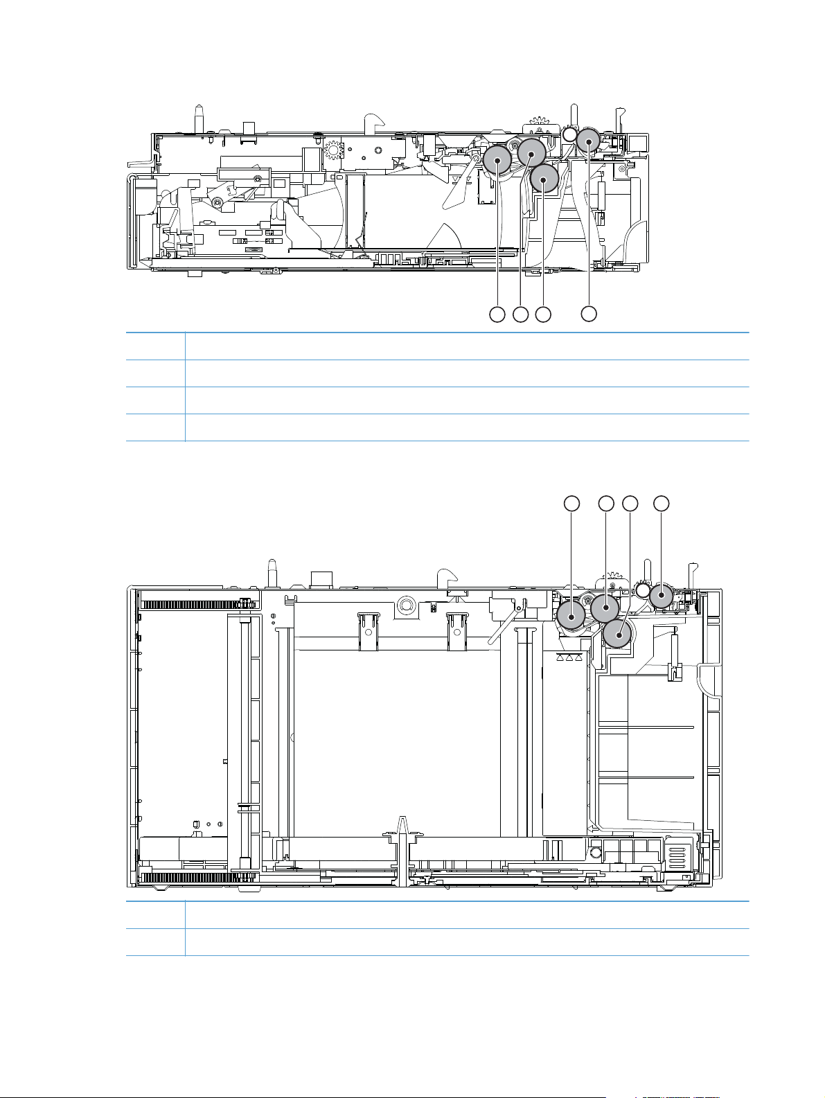
Figure 1-3 Internal components, 1x500-sheet feeder
1 Pickup roller
2 Feed roller
3 Separation roller
4 Feed roller
Figure 1-4 Internal components, 1,500-sheet paper deck
321
4
321 4
1 Pickup roller
2 Feed roller
4 Chapter 1 Theory of operation ENWW
Page 29

3 Separation roller
4 Feed roller
Figure 1-5 Internal components, envelope feeder
321 4 65
1 Feed roller
2 Upper separation roller
3 Lower separation roller
4 Separation guide
5 Weight
6 Pickup roller
ENWW
Basic operation
5
Page 30
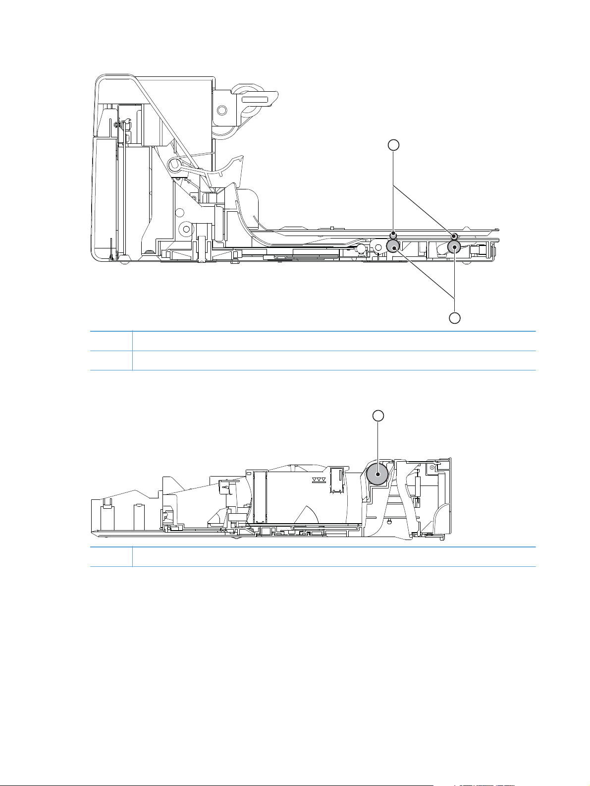
Figure 1-6 Internal components, duplexer
1 Oblique rollers
1
2
2 Re-pickup rollers
Figure 1-7 Internal components, custom media cassette
1 Separation roller
1
6 Chapter 1 Theory of operation ENWW
Page 31

Operating sequence
A microprocessor on the DC controller PCA controls the product operating sequence. The following
table describes the basic operating sequence from when the product power is turned on until the final
printed page is delivered to an output bin.
NOTE: The product takes about two minutes and twenty seconds to initialize.
Table 1-1 Product operating sequence
Period Duration Operation
WAIT From the time the power is turned on, the
door is closed or Sleep mode is released
until the product gets ready for a print
operation.
STBY
(Standby)
INTR (Initial
rotation
period)
PRINT From the end of INTR period until the last
LSTR (Last
rotation
period)
From the end of WAIT or LSTR period
until either the print command is received
from the formatter or the power button is
turned off.
From the time the print command is
received from the formatter until the
media is picked up.
paper completes the fixing operation.
From the end of PRINT period until the
motors stop rotating.
Brings the product to standby condition.
●
Pressurizes the fuser pressure roller.
●
Detects the print cartridge.
●
Maintains the product in printable condition.
●
Puts the product in Sleep mode when the formatter sends a
●
sleep command.
Starts up each high-voltage bias, laser/scanner unit, and fuser for
printing.
Forms the image on the photosensitive drum based on the
●
signals from the formatter.
Transfers and fuses the toner image to the print media.
●
Moves the last printed sheet out of the product.
●
Stops the laser/scanner unit operation and high-voltage
●
biases.
The product enters the INTR period as soon as the LSTR period is
completed, if the formatter sends another print command.
ENWW
Basic operation
7
Page 32

Formatter system
The formatter is involved in the following procedures.
Controlling the Sleep mode
●
Receiving and processing print data from the various product inputs
●
Monitoring control-panel functions and relaying product status information (through the control
●
panel and the bidirectional input/output)
Developing and coordinating data placement and timing with the DC controller PCA
●
Storing font information
●
Communicating with the host computer through the bidirectional interface
●
The formatter receives a print job from the bidirectional interface and separates it into image
information and instructions that control the printing process. The dc controller PCA synchronizes the
image-formation system with the paper-input and -output systems, and then signals the formatter to send
the print-image data.
The formatter also provides the electrical interface and mounting locations for the memory DIMM and
the hard-disk (hard disk drive or solid state drive).
Sleep mode
When the product is in Sleep mode, the control-panel backlight is dimmed, but the product retains all
product settings, downloaded fonts, and macros. The default setting is a 30-minute idle time. Sleep
mode also can be turned off from the Administration menu on the control panel.
The product exits Sleep mode and enters the warm-up cycle when any of the following occurs.
A print job, valid data, or a PML or PJL command is received at the serial port.
●
A control panel key is pressed.
●
The top cover is opened.
●
The engine-test button is pressed.
●
NOTE: Error messages override the Sleep message. The product enters Sleep mode at the
appropriate time, but the error message continues to appear.
Input/output
The following sections discuss the input and output features of the product.
USB
The product includes a universal serial bus (USB) 2.0 connection.
8 Chapter 1 Theory of operation ENWW
Page 33

Embedded print server
For all models except the HP LaserJet 4014 base model, the product includes an HP Jetdirect
embedded print server for connecting to a 10/100Base-TX network.
Hard-disk
The hard-disk is mounted on the formatter cage door. The hard disk is used for creating multiple
original prints (mopies) and storing forms, fonts, and signatures.
NOTE: All models have a solid state module (SSM) installed except the HP LaserJet Enterprise 600
M603xh.
CPU
The product formatter incorporates a 800 MHz RISC processor.
Memory
If the product encounters a problem when managing available memory, a clearable warning message
appears on the control panel.
Random-access memory
The formatter has one DIMM slot. All models come with 512MB of memory installed. Additional
memory can be added up to a maximum of 1GB.
The random-access memory (RAM) contains the page, I/O buffers, and the font storage area. It stores
printing and font information received from the host system, and can also serve to temporarily store a
full page of print-image data before the data is sent to the print engine. Memory capacity can be
increased by adding DIMMs to the formatter. Note that adding memory (DIMMs) might also increase
the print speed for complex graphics.
Nonvolatile memory
The product uses nonvolatile memory (NVRAM) to store I/O and information about the print
environment configuration. The contents of NVRAM are retained when the product is turned off or
disconnected.
DIMM slot
The DIMM slot can be used to add product memory.
ENWW
Formatter system
9
Page 34

PJL overview
Printer job language (PJL) is an integral part of configuration, in addition to the standard printer
command language (PCL). With standard cabling, use PJL to perform a variety of functions.
Two-way communication with the host computer through a bidirectional parallel connection. The
●
product can send the host computer information about such things as the control panel settings,
and the control panel settings can be changed from the host through two-way communication.
Dynamic I/O switching. The product can be configured with a host on each I/O by using
●
dynamic I/O switching. Even when the product is offline, it can receive data from more than one
I/O simultaneously, until the I/O buffer is full.
Context-sensitive switching. The product can automatically recognize the personality (PS or PCL) of
●
each job and configure itself in that personality.
Isolation of print environment settings from one print job to the next. For example, if a print job is
●
sent to the product in landscape mode, the subsequent print jobs are printed in landscape mode
only if they are formatted for it.
PML
The printer management language (PML) allows remote configuration and status monitoring through the
I/O ports.
Control panel
The formatter sends and receives product status and command data to and from a control-panel PCA.
10 Chapter 1 Theory of operation ENWW
Page 35

Engine-control system
The engine control system coordinates all product functions and controls all the other systems according
to commands from the formatter. The engine control system contains the following components:
DC controller
●
Low-voltage power supply
●
High-voltage power supply
●
Fuser control
●
Figure 1-8 Engine-control system
ENGINE CONTROL SYSTEM
Low-voltage power supply
DC controller
LASER/SCANNER SYSTEM
Formatte
r
High-voltage power supply
Fuser control
IMAGE-FORMA TION SYSTEM
PICKUP-AND-FEED SYSTEM
ENWW
Engine-control system
11
Page 36

DC controller PCA
The DC controller PCA controls the operation of the product and its components. The DC controller PCA
starts product operation when the power is turned on and the power supply sends DC voltage to the
DC controller PCA. After the product enters the standby sequence, the DC controller PCA sends out
various signals to operate motors, solenoids, and other components based on the print command and
image data that the host computer sends.
Figure 1-9 DC controller PCA
AC input
Transfer roller
Cartridge
Fuser unit
Fuser control
Low-voltage
power supply
High-voltage
power supply
DC controller
CL
M
Clutch
Fan
Motor
Solenoid
Switch
Sensor
Sensor
Option
Power supply unit
Walkup
USB port
Formatter
Laser/scanner
unit
12 Chapter 1 Theory of operation ENWW
Page 37

Sensors, solenoids, and switches
The product has twelve sensors, two solenoids, and three switches. Sensors are used for remote
detection of various functions during product operation. Solenoid and switches are used for product
operation control.
Table 1-2 Sensors, solenoids, and switches
Description Item Component
Sensors PS101 Cassette media presence senor
PS102 Pre-feed sensor
PS103 Top-of-page sensor
PS104 Face-down tray media full sensor
PS105 MP tray (Tray 1) media presence sensor
PS106 Media width sensor 1
PS107 Media stack surface sensor 1
PS108 Media width sensor 2
PS699 Fixing (fuser) pressure release sensor
PS700 Fixing (fuser) delivery sensor
PS907 Media stack surface sensor 2
TH3 Environmental sensor
Solenoids SL101 Casette pickup solenoid
SL102 MP tray (Tray 1) pickup solenoid
Switches SW101 Door open detection switch
SW102 Cassette media size switch
SW800 Test print switch
ENWW
Engine-control system
13
Page 38

Motors and fans
The product has four motors and four fan motors. The motors are used for the media feeding and image
formation. The fan motors are used for preventing a temperature rise inside the product.
Table 1-3 Fans
Description Cooling area Type Speed
Cooling fan FN101 Cartridge area and power supply area Intake
Cooling fan FN102 Cartridge area Intake
Cooling fan FN103 Cartridge area Intake
Cooling fan FN301 Cartridge area and laser/scanner Intake
1
Cooling fan FN101 rotates at full speed for eight seconds when the product is turned on, and then decreases to half-speed for
approximately 10 minutes. After that time period, if there is no print job in the print queue, the fan will stop completely. The
fan rotates at full speed during a print job.
2
This fan operates at full speed only during a print job. Otherwise, it does not rotate.
Full/Half
Full
Full
Full
1
2
2
2
Table 1-4 Motors
Description Driving parts Type Failure
detection
Paper feed motor (M101) Drives the Tray 1 pickup roller, Tray 2 pickup roller,
and feed roller
Drum motor (M102) Drives the photosensitive drum, primary charging roller,
and transfer roller
Fuser motor (M299) Drives the pressure roller and feed roller—when rotated
counterclockwise it releases the fusing pressure for
easier jam removal
DC Yes
DC Yes
DC Yes
Lifter motor (M103) Drives the lifting plate of the tray DC No
Failure detection
Motor failure
The DC controller determines a motor failure and notifies the formatter when it encounters the following
conditions:
Motor start-up failure: The motor does not reach a specified speed within a specified period
●
from when each motor starts up.
Motor rotational failure: The rotational speed of the motor is out of a specified range for a
●
specified period from when it once reaches a specified speed.
Fan motor failure
The DC controller determines a fan motor failure and notifies the formatter when the fan locks for a
specified period from when each fan starts up.
14 Chapter 1 Theory of operation ENWW
Page 39

Engine power supply
The power supply consists of the fuser-control circuit, the high-voltage circuit, and the low-voltage
circuit. The fuser-control and high-voltage circuits control the temperature of the fuser and generate highvoltage according to signals from the DC controller PCA. The low-voltage circuit generates the DC
voltages that other components in the product use (for example the DC controller PCA, the motors, and
fans).
Fuser-control circuit
The fuser-control circuit controls the fuser components. The two fuser heaters provide the high
temperatures that cause the toner to permanently bond to the media. The fuser thermistor monitors the
fuser temperatures. The thermal switch detects abnormally high fuser temperatures and interrupts the
supply of voltage to the fuser if the temperature is too high.
Figure 1-10 Fuser control
TH2
Fuser sleeve
H1
TH1
TP1
Pressure roller
FUSER HEATER TEMPERATURE signal
Fuser control
FUSER HEATER
DRIVE signal
Fuser heater
drive circuit
Relay
Fuser heater
safety circuit
CPU
DC controller
ENWW
Engine-control system
15
Page 40

Fuser temperature control
The fuser temperature control detects the temperature of the fuser heater surface, and then controls the
FUSER HEATER DRIVE (FSRD1) signal to the fuser heater until the fuser heater temperature reaches the
target temperature.
The DC controller controls the FSRD1 signal by monitoring the detected fuser heater temperature—using
the thermistor (TH3)—and then holds the heater at the target temperature.
Figure 1-11 Fuser temperature control
AC input
Zero crossing
+24VC
Relay
(RL102)
Fuser heater
drive circuit
TB11
circuit
Relay
(RL101)
TB10
Fuser control
Current
detection circuit
JP1001
100V: Open
200V: Close
/ZEROX
/RLD
FSRSAFE
CURRMS
FSRD1
FSRTH2
/AC200
FSRTH1
DC controller
Fuser heater
safety circuit
+3.3V
Q704
CPU
/HITMP
J128
/FSRARI
TH2
TH1
TP1
H1
2
1
16 Chapter 1 Theory of operation ENWW
Page 41

Low-voltage power supply
The low-voltage power supply converts AC power from the power receptacle into DC power to cover
the DC loads.
Figure 1-12 Low-voltage power supply
Power supply unit
Power button
(SW1)
Fuse
(FU2)
Noise
filter
Rectifying
circuit
Low-voltage power supply
Fuse
(FU1)
Control IC
(IC1)
Noise
filter
Transformer
(T1)
Constant-
voltage control
photocoupler
(PC2)
Abnormal
status latch
photocoupler
(PC1)
ACH
ACN
Rectifying
circuit
Rectifying
circuit
Constant-
voltage
control circuit
Protection
circuit
Fuser
control
5VPRO
+24VA
+3.3V
+24U
Sleep
switch 2
Sleep
switch 1
DC controller
generation circuit
+3.3R
Sleep
switch 3
+24R
/DOPEN
+24VC
+5V
+5V
+24VA
ENWW
100V: Open
200V: Close
JP1001
High-voltage
power supply
+24VB
/AC200
+24VA
Door open
detection switch
(SW101)
+24VC
Engine-control system
17
Page 42

High-voltage power supply
The high-voltage power supply applies the high-voltage biases to the following components:
Primary charging roller
●
Developing roller
●
Transfer roller
●
Fuser sleeve
●
Pressure roller
●
Figure 1-13 High-voltage power supply
Cartridge
From antenna
From antenna
Photosensitive drum
Fuser sleeve
Pressure roller
FILMBIAS
TB20 TB504
high-voltage
generation circuit
High-voltage power supply
Power supply unit
KAATUBIAS
TB21
Fuser
Primary charging
high-voltage
generation circuit
To primary charging roller
T503
Transfer
high-voltage
generation circuit
TRAD
To developing cylinder
Transfer roller
TB502
Developing high-
voltage generation
circuit
ANT2
TB501
Toner level detection
circuit
TNRSP2
ANT1
TB503
TNRSP1
DC controller
18 Chapter 1 Theory of operation ENWW
Page 43

Overcurrent/overvoltage protection
If a short-circuit or other problem on the load side causes an excessive current flow or generates
abnormal voltage, the overcurrent/overvoltage protection systems automatically cut off the output
voltage to protect the power-supply circuit.
If the overcurrent or overvoltage protection system are activated and the power-supply circuit does not
generate DC voltage, turn the power off, correct the problem, and then turn the product on again.
The circuit has two fuses (FU1, FU2), which break and cut off the output voltage if overcurrent flows
through the alternating current (AC) line.
ENWW
Engine-control system
19
Page 44

Image-formation system
The image-formation system is the central hub of the product. It forms the toner image on the media.
The following are the main components of the image-formation system:
Cartridge
●
Transfer roller
●
Fuser
●
The DC controller controls the laser/scanner unit and high-voltage power supply to form an image on
the media according to the VIDEO signals.
20 Chapter 1 Theory of operation ENWW
Page 45

Image-formation process
The image formation system is the central hub of the product. It also forms the toner image on the
media.
Figure 1-14 Image-formation system
Cartridge
Fuser sleeve
Pressure roller
TB20
TB21
High-voltage power supply circuit
Laser/scanner unit
To primary charging roller
Transfer roller
TB504 T503 TB502
DC controller
Laser beam
Photosensitive drum
To developing cylinder
Power supply unit
ENWW
VIDEO signal
Formatter
The image-formation process contains eight steps divided among five functional blocks:
Block 1: Latent image formation
●
Step 1: Primary charging
Step 2: Laser-beam exposure
Block 2: Developing
●
Step 3: Developing
Block 3: Transfer
●
Image-formation system
21
Page 46

Step 4: Transfer
Step 5: Separation
Block 4: Fusing
●
Step 6: Fusing
Block 5: Drum cleaning
●
Step 7: Drum cleaning
Step 8: Drum charge elimination
Figure 1-15 Image-formation process
Media path
Direction of the drum rotation
Block
Step
Latent image formation
2. Laser-beam exposure
1. Primary charging
Developing
Delivery
Drum cleaning
6. Fuser
Fuser
8. Drum charge elimination
7. Drum cleaning
5. Separation
4. Transfer
Transfer
3. Developing
Pickup
22 Chapter 1 Theory of operation ENWW
Page 47

Block 1: Latent image formation
During the two steps that comprise this block, an invisible latent image is formed on the photosensitive
drum.
Step 1: Primary charging
To prepare for latent image formation, the surface of the photosensitive drum is charged with a uniform
negative potential. The product charges the photosensitive drum surface directly from the primary
charging roller. The DC bias and AC bias are applied to the primary charging roller to maintain a
constant charge on the drum surface.
Figure 1-16 Primary charging
Primary charging roller
AC bias
Photosensitive drum
Step 2: Laser-beam exposure
The laser beam scans the photosensitive drum to neutralize the negative charge on portions of the drum
surface. An electrostatic latent image forms where the negative charge was neutralized.
Figure 1-17 Laser-beam exposure
Unexposed area Exposed area
DC bias
Laser beam
ENWW
Image-formation system
23
Page 48

Block 2: Developing
Toner adheres to the electrostatic latent image on the photosensitive drum.
Step 3: Developing
Toner acquires a negative charge from the friction that occurs when the developing cylinder rotates
against the developing blade. The negatively charged toner is attracted to the latent image on the
photosensitive drum surface because the drum surface has a higher potential. The AC bias that is
superimposed with the developing negative DC bias is applied to the developing cylinder.
Figure 1-18 Developing
Blade
Developing cylinder
Exposed area
Unexposed area
Unexposed area
AC bias
Exposed area
DC bias
Photosensitive drum
24 Chapter 1 Theory of operation ENWW
Page 49

Block 3: Transfer
During the steps that comprise this block, a toner image on the photosensitive drum is transferred to the
print media.
Step 4: Transfer
The positive DC bias is applied to the transfer roller to charge the media positive. The positively
charged media attracts the negatively charged toner from the photosensitive drum surface.
Figure 1-19 Transfer
Transfer roller
Photosensitive
drum
Media
DC bias
Step 5: Separation
The curvature elasticity of the print media causes it to separate from the photosensitive drum surface.
The static charge eliminator reduces back side static discharge of the media for stable media feed and
image quality.
Figure 1-20 Separation
Static charge eliminator
Photosensitive
drum
Media
Transfer roller
ENWW
Image-formation system
25
Page 50

Block 4: Fusing
The toner image is fixed onto the print media.
Step 6: Fusing
The product uses the on-demand fixing method to fix the toner image onto the media. The image is
permanently affixed to the print media by the heat and pressure.
Figure 1-21 Fusing
Fuser heater
Brush
Fuser sleeve
DC bias
Pressure roller
Toner
Media
DC bias
26 Chapter 1 Theory of operation ENWW
Page 51

Block 5: Drum cleaning
The residual (waste) toner is cleared from the photosensitive drum surface to prepare for the next latent
image formation.
Step 7: Drum cleaning
The cleaning blade scrapes the residual toner off the surface of the photosensitive drum and deposits it
in the waste toner container.
Figure 1-22 Drum cleaning
Cleaning blade
Photosensitive
Waste toner container
Step 8: Drum charge elimination
drum
The residual charge on the photosensitive drum surface is eliminated to avoid uneven image. The
residual charge of the previous image is left on the drum surface after the transfer operation and this
affects the following image formation. The product eliminates this residual charge by emitting a laser
beam to the drum surface. The drum charge elimination is operated only during the last rotation period.
Figure 1-23 Drum charge elimination
Laser beam
ENWW
Image-formation system
27
Page 52

Laser/scanner system
The laser/scanner system forms a latent image on the photosensitive drum according to the VIDEO
signals sent from the formatter. The main components, such as the laser driver and scanner motor, are
assembled as a laser/scanner unit and controlled by the DC controller. The DC controller allows the
laser to emit light according to the VIDEO signals. The laser beam passes through the lenses and enters
28 Chapter 1 Theory of operation ENWW
Page 53

the scanner mirror that is rotating at constant speed. The laser beam is reflected by the scanner mirror,
passes through the lenses, and scans on the photosensitive drum.
Figure 1-24 Laser/scanner system
Formatter
DC controller
VIDEO signal
BD INPUT signal
SCANNER MOTOR
Scanner mirror
Scanner motor unit
SPEED CONTROL signal
LASER CONTROL signal
Laser driver
BD PCA
Photosensitive drum
The laser scanner uses two laser diodes to scan two lines simultaneously, producing high-speed laser
scanning. After receiving the print command from the host computer, the DC controller PCA activates
the scanner motor, which rotates the six-sided scanner mirror. The laser-driver PCA emits light from the
two laser diodes according to signals from the DC controller PCA. The two laser beams strike the sixsided scanning mirror and are directed through the focusing lenses and onto the photosensitive drum.
ENWW
Laser/scanner system
29
Page 54

The modulated laser beams generate the latent electrostatic image on the photosensitive drum
according to the image data signals that the DC controller PCA sends.
1. As it receives a print command from the formatter, the dc controller outputs the SCANNER
MOTOR SPEED CONTROL signal (/ACC) and rotates the scanner motor in order to rotate the sixsided mirror.
2. As the scanner motor starts rotating, the dc controller uses a LASER CONTROL signal (CNT0,
CNT1, CNT2) to receive the /BD INPUT signal (/BDI) and force the laser to emit light . The dc
controller detects the rotational speed of the scanner motor based on the timing the /BD1 signal is
input and controls the speed to keep it constant.
3. While the scanner motor rotates at a constant speed, the dc controller passes the VIDEO signals
from the formatter on to the laser driver PCA. The laser driver PCA emits light from the two laser
diodes according to these signals: VDO1, /VDO1, VDO2, /VDO2.
4. The two laser beams pass through the collimator lens and cylindrical lens and strike the six-sided
mirror that is rotating at a constant speed.
5. The laser beams, that are reflected off of the six-sided mirror pass through the focus lens and
reflective mirror and focus on the photosensitive drum. The laser beams scan the drum surface at a
constant speed.
6. As the six-sided mirror rotates and the laser beam scans the drum surface at a constant speed, a
latent image forms on the drum surface.
Laser failure detection
The DC controller determines a laser/scanner unit failure and notifies the formatter, if the laser/scanner
unit encounters the following conditions:
Laser failure: The laser intensity is not detected for a specified value when the laser is turned on
●
for a specified period during the scanner unit start-up period.
BD failure: The BD interval is out of a specified value during a print operation.
●
Scanner motor start-up failure: The scanner motor does not reach a specified rotation within
●
a specified period from when the scanner motor starts rotation.
30 Chapter 1 Theory of operation ENWW
Page 55

Pickup, feed, and delivery system
The pickup, feed, and delivery system consists of various rollers that the product motors drive. The
product uses Tray 1 (the manual feeding tray) and a cassette in Tray 2 as media sources. The printed
media is delivered to either the rear output bin (straight-through printing) or the top output bin (the
default destination). A number of 1x500-sheet feeders and one 1,500-sheet paper deck can be added
to certain models. These accessories are discussed later in this chapter. The Tray 1 paper sensor (on the
Tray 1 pickup assembly; PS105) detects media in Tray 1. The Tray 2 paper sensor (PS101) detects
media in Tray 2. The paper-size switch (SW102) detects the media size that is loaded in Tray 2.
Two motors, a clutch, and a solenoid that are controlled by the DC controller PCA drive all of the rollers
in the product.
The pre-feed, top-of-page, and fuser-assembly delivery sensors (PS102, PS103, PS700) detect media
arriving and passing along the paper path. If the media does not reach or pass these sensors within a
specific amount of time, the microprocessor on the DC controller PCA halts the product functions and a
jam error message appears on the control-panel display.
Figure 1-25 Pickup, feed, and delivery system
PS104
Face-down delivery roller
PS699
PS700
Pressure roller
SW102
Fixing sleeve
Lifting plate
Photosensitive drum
Transfer roller
PS101
Lifter
Registration shutter
PS103
PS106
PS107
PS907
Pickup roller
Pre-transfer roller
PS108
Feed roller
PS102
Pickup arm
Lifting plate
PS105
Feed roller
Separation roller
The pickup-and-feed system is divided into two blocks: The pickup-and-feed block and the fuser/delivery
block.
ENWW
Pickup, feed, and delivery system
31
Page 56

Figure 1-26 Pickup, feed, and delivery blocks
Face-down delivery
Fixing/delivery unit
Face-up delivery
Pickup/feed unit
Pickup-and-feed block
The following functions take place in the pickup-and-feed block:
Detection of media
●
Detection of media-size
●
Detection of media entering the paper path from Tray 1 or Tray 2
●
Lifting of the Tray 2 paper plate
●
Prevention of multiple-feeds
●
Correction of page skew
●
When it receives a print command from the host computer, the DC controller PCA turns on the feed
motor (M101) power. The motor drives the Tray 2 pickup, feed, and separation rollers. The drum motor
power also turns on. The laser/ scanner motor power turns on.
The DC controller PCA then activates the feed clutch (CL101) to rotate the feed roller. The Tray 2 pickup
solenoid is activated (SL101) and the pickup arm descends. The pickup roller touches the media and a
sheet is fed into the product. The separation roller prevents multiple sheets of media from being fed at
one time.
As the pre-feed sensor (PS102) detects the media, the dc controller PCA turns off the clutch, which stops
the media. When the DC controller PCA detects that the laser/scanner is ready it activates the feed
32 Chapter 1 Theory of operation ENWW
Page 57

clutch again. The feed roller moves the media farther into the product. The registration shutter corrects
page skew and the media is transported to the fuser/delivery block.
Fuser/delivery block
The fuser/delivery block consists of rollers, sensors, the fuser, and the output delivery assembly. The
rollers transport the media through the fuser/delivery block paper path. The fuser applies heat and
pressure to the media to permanently bond the toner image to the media. The output delivery assembly
sends the printed media either to the rear output bin (if the rear output door is open) or to the top output
bin (the default output delivery bin). Sensors along the paper path detect media movement, jams, and
the top output-bin capacity.
Pressure roller pressure release control
The product releases the pressure roller except during a print operation to improve usability for jammed
paper removal.
The DC controller reverses the fuser motor (M299) to rotate the fuser pressure release cam. The
pressure roller is pressurized or depressurized due to the shape of the cam.
The DC controller reverses the fuser motor to control the pressure roller pressurize or depressurize state
according to the signal sent from the fuser pressure release sensor (PS699).
Figure 1-27 Pressure roller pressure release control
DC controller
DRIVE signal
FIXING MOTOR
M299
FIXING PRESSURE RELEASE signal
Fuser pressure
Fuser pressure release sensor
Fuser motor
release cam
PS699
Pressure roller
ENWW
Fuser sleeve
<Pressurized> <Released>
Pickup, feed, and delivery system
33
Page 58

The pressure roller pressure is released under the following conditions:
A paper jam is detected
●
Factory shipment
●
The DC controller determines a fuser pressure release mechanism failure and notifies the formatter if the
fuser roller release control is not completed within a specified period when it reverses the fuser motor.
Paper trays
Printing from Tray 1
The Tray 1 paper sensor (PS105) detects the presence of media in Tray 1. When the DC controller PCA
receives the print command, the product starts the initial rotation phase, which consists of feed motor
warm-up, scanner motor warm-up, high-voltage control sequence, and fuser warm-up. When the initial
rotation phase ends, the Tray 1 pickup solenoid (SL102) is activated.
The cam rotates, the paper-tray lifter rises, and the media comes in contact with the Tray 1 pickup
roller. At the same time, the Tray 1 pickup roller rotates twice and picks up a sheet of media from
Tray 1. The separation pad prevents additional sheets from feeding with the first sheet.
The sheet then reaches the registration assembly, where its skew is corrected. The sheet then passes
through the transfer, separation, and fusing stages; through the delivery unit; and is to the output bin.
NOTE: If media is removed from Tray 1 after the initial rotation phase, but before the pickup roller
pulls the media from the tray, the Tray 1 pickup roller might continue to rotate up to six times, after
which a jam detected.
Printing from Tray 2
When the DC controller PCA receives the print command, the feed motor (M101) and scanner motor
start their rotation. When the feed motor reaches its prescribed speed, the feed roller clutch (CL101)
and Tray 2 pickup solenoid (SL101) are activated. (The feed motor rotation drives the Tray 2 pickup
roller, Tray 2 feed roller, Tray 2 separation roller, and paper-feed rollers.)
The Tray 2 pickup roller, which the pickup solenoid activates, rotates once and picks up the media in
the tray. The separation roller prevents additional sheets from feeding with the first sheet, and the
media is fed to the pre-feed sensor (PS102).
The sheet then reaches the registration assembly, where its skew is corrected. The sheet then passes
through the transfer, separation, and fusing stages; through the delivery unit; and to the output bin.
Cassette media size detection and cassette presence detection
The media size detection switch (SW102) detects the size of media loaded in the cassette and the
presence of the cassette.
The media size detection switch—comprised of three switches: upper, center, and lower—is active
when the cassette media size plate is correctly positioned to the loaded paper size and the cassette is
installed in the product. The DC controller determines the paper size by monitoring the switch
conditions.
34 Chapter 1 Theory of operation ENWW
Page 59

the DC controller determines a size mismatch and sends a signal to the formatter if the switches detect a
paper size that is different from the size specified by the formatter.
Table 1-5 Cassette media size detection and cassette presence detection (Tray 2 and 1x500-
sheet feeder)
Media size Media size switch settings
Upper Center Lower
No cassette Off Off Off
A4 Off Off On
B5 Off On On
A5 On Off Off
LegalOnOnOff
Letter Off On Off
Executive On Off On
Universal On On On
ENWW
Pickup, feed, and delivery system
35
Page 60

Jam detection
The product uses the following sensors to detect the presence of media and to check whether media is
being fed correctly or has jammed
Figure 1-28 Jam detection sensors
PS106
PS108
PS103
PS700
PS102
PS1603
PS1603
PS1603
PS1704
PS102: Pre-feed sensor PS108: Media width sensor 2 PS1704: Media path sensor (paper
deck)
PS103: Top of page sensor PS700: Fuser delivery sensor
PS106: Media width sensor 1 PS1603: Media path sensor (paper
feeder)
The product determines a jam if the sensor detects paper presence at a specified timing stored in the
DC controller.
The DC controller stops a print operation and notifies the formatter when it determines a jam
occurrence.
The product detects the following jams.
36 Chapter 1 Theory of operation ENWW
Page 61

Pickup delay jam 1
a. Standard equipped cassette
The top of page sensor (PS103) does not detect the leading edge of media within a specified
period from when the pre-feed sensor (PS102) detects the leading edge.
b. Pickup option
The top of page sensor (PS103) does not detect the leading edge of media within a specified
period from when the feed clutch (CL101) is turned on.
c. MP tray (Tray 1)
The top of page sensor (PS103) does not detect the leading edge of media within a specified
period from when the MP tray pickup solenoid (SL102) is turned on.
Pickup delay jam 2
a. Standard equipped cassette
The pre-feed sensor (PS102) does not detect the leading edge of media within a specified
period from when a pickup operation starts.
b. Top pickup source of pickup option
The PF media path sensor (PS1603) for the top PF cassette or the PD media path sensor
(PS1704) does not detect the leading edge of media within a specified period from when a
pickup operation starts.
c. Lower pickup sources of pickup option
The PF media path sensor (PS1603) for the top PF cassette does not detect the leading edge
of media within a specified period from when the PF media path sensor (PS1603) or the PD
media path sensor (PS1704), either one of that equipped to the pickup source that picks up
the media, detects the leading edge of media.
Pickup delay jam 3
The PF media path sensor (PS1603) or PD media path sensor (PS1704), either one of that
equipped to the pickup source that picks up the media, does not detect the leading edge of media
within a specified period from when a pickup operation from the lower pickup sources of the
pickup option.
Pickup stationary jam
a. Top of page sensor detection
The top of page sensor (PS103) does not detect the trailing edge of media within a specified
period from when it detects the leading edge.
ENWW
b. Media width sensors detection
Both of the media width sensors (PS106, PS108) do not detect the trailing edge of media
within as pecified period from when the top of page sensor (PS103) detects the trailing edge.
Pickup, feed, and delivery system
37
Page 62

Delivery delay jam
The fuser delivery sensor (PS700) does not detect the leading edge of media within a specified
period from when the top of page sensor (PS103) detects the leading edge.
Delivery stationary jam
The fuser delivery sensor (PS700) does not detect the trailing edge of media within a specified
period from when the top of page sensor (PS103) detects the trailing edge.
Residual media jam 1
a. Either one of the following sensors detects media presence when the wait sequence starts:
Top of page sensor (PS103)
◦
Media width sensors (PS106, PS108)
◦
Fixing delivery sensor (PS700)
◦
b. The fuser delivery sensor (PS700) detects media presence before the top of page sensor (PS103)
or the media width sensor (PS106, PS108) detects leading edge of media during an automatic
delivery operation.
NOTE: The automatic delivery delivers the deliverable residual media automatically during the
initial rotation period when the power is turned on or when the door is closed. The DC controller
sends an automatic delivery request to the formatter and stops a print operation when it
determines that there is deliverable residual media. Then the formatter sends an automatic delivery
command and the DC controller drives media feed system to deliver the residual media out of the
product.
c. Either one of the following sensors detects media presence during an automatic delivery
operation:
Pre-feed sensor (PS102)
◦
Top of page sensor (PS103)
◦
Media width sensors (PS106, PS108)
◦
Fuser delivery sensor (PS700)
◦
PF media path sensor (PS1603)
◦
PD media path sensor (PS1704)
◦
38 Chapter 1 Theory of operation ENWW
Page 63

d. The door open is detected when either one of the following sensors detects media presence during
an automatic delivery operation:
Top of page sensor (PS103)
◦
Media width sensors (PS106, PS108)
◦
Fuser delivery sensor (PS700)
◦
e. A stop control command is received when either one of the following sensors detects media
presence during an automatic delivery operation:
Pre-feed sensor (PS102)
◦
Top of page sensor (PS103)
◦
Media width sensors (PS106, PS108)
◦
Fuser delivery sensor (PS700)
◦
PF media path sensor (PS1603)
◦
PD media path sensor (PS1704)
◦
Residual media jam 2
a. Either one of the following sensors detects media presence when a print operation completes:
◦
◦
◦
◦
◦
◦
b. A stop control command is received from the formatter after a pickup operation has started.
Door open jam
The door open is detected after a pickup operation has started.
Wrapping jam
The fuser delivery sensor (PS700) detects media absence before it detects the trailing edge of
media after a specified period from when it detects the leading edge.
Pre-feed sensor (PS102)
Top of page sensor (PS103)
Media width sensors (PS106, PS108)
Fuser delivery sensor (PS700)
PF media path sensor (PS1603)
PD media path sensor (PS1704)
ENWW
Pickup, feed, and delivery system
39
Page 64

1x500-sheet paper feeder
The 1x500-sheet paper feeder (PF) is optionally installed at the bottom of the product. It features paper
pickup and paper feeding to the product. The product supports up to four optional paper feeders.
Figure 1-29 1x500-sheet paper feeder
Face-down delivery
Face-up delivery
Paper Feeder
The paper feeder driver controls the operational sequence of the paper feeder and the serial
communication with the DC controller of the product.
The DC controller sends several commands to the paper feeder driver at necessary timing. The paper
feeder driver drives each load, such as motor and solenoid, according to the commands. The paper
feeder driver responds the status information of the paper feeder to the DC controller.
The DC controller determines a paper feeder illegal connection and notifies the formatter if it does not
make the serial communication with the paper feeder driver during the pre-rotation period when the
product is turned on, when recovering from the Sleep mode or when the door is closed.
The product supplies DC24V to the paper feeder. The DC3.3V for sensors and ICs is generated from
the DC24V in the paper feeder driver.
40 Chapter 1 Theory of operation ENWW
Page 65

Figure 1-30 1x500-sheet paper feeder circuit diagram
+3.3V +24V
+3.3V
generation
+24V
circuit
M
Paper feeder
Motor
Solenoid
DC controller
Paper feeder driver
Paper feeder/Paper deck
Component Description
Motor M1600 Paper feeder lift motor
Sensor PS1600 Paper feeder media presence sensor
PS1601 Paper feeder media stack surface sensor 1
PS1602 Paper feeder media stack surface sensor 2
PS1603 Paper feeder media path sensor
Solenoid SL1600 Paper feeder pickup solenoid
Switch SW1600 Paper feeder media size switch
Switch
Sensor
Pickup-and-feed operation (PF)
The paper feeder uses same mechanism of the product for the pickup-and-feed operation. The rollers
used in the paper feeder are driven by the feed motor (M101) of the product through the gears.
Pickup and feed sequence of operation (PF)
1. The lifting plate moves up to the position where the paper can be picked up after the product is
turned on or the paper feeder cassette is installed.
2. The DC controller drives the feed motor (M101) when it receives a print command from the for-
matter.
3. The DC controller outputs a pickup command to the paper feeder driver.
4. The paper feeder driver turns on the PF pickup solenoid (SL1600) when it receives a pickup
command. Accordingly the PF pickup roller, PF feed roller and PF feed roller 1 rotate to pick up
ENWW
1x500-sheet paper feeder
41
Page 66

media in the PF cassette. (PF cassette pickup mechanism and PF lift-up operation are the same way
as that of the product).
5. The PF separation roller holds back any multiple-fed sheets and one sheet of media is fed into the
product. (PF multiple-feed prevention mechanism is the same way as that of the product).
Figure 1-31 1x500-sheet paper feeder block diagram
Feed motor
SL1600
PF feed roller 1
PF feed roller
PS1600
PS1601
PF pickup roller
M1600
PF separation roller
Pickup arm
PS1602
SW1600
Description Signal Driver
Lifter
Lifting plate
M101
PS1603
PF lifter motor M1600 PF LIFTER MOTOR DRIVE signal PF driver
PF media presence
sensor
Paper feeder media
stack surface sensor 1
Paper feeder media
stack surface sensor 2
Paper feeder media
path sensor
Paper feeder pickup
solenoid
Paper feeder media size
switch
PS1600 PF MEDIA PRESENCE signal PF driver
PS1601 PF MEDIA STACK SENSOR 1 signal PF driver
PS1602 PF MEDIA STACK SENSOR 2 signal PF driver
PS1603 PF MEDIA PATH signal PF driver
SL1600 PF PICKUP SOLENOID signal PF driver
SW1600 PF MEDIA SIZE signal PF driver
42 Chapter 1 Theory of operation ENWW
Page 67

Cassette lift operation (PF)
The lift-up operation keeps the stack surface of media in the paper feeder cassette at a specified
position to perform stable pickup operation.
The paper feeder driver drives the PF lifter motor (M1600) to move up the lifter plate in which media is
stacked. The cassette lift-up operation for the paper feeder is operated in the same way as that of the
product base.
The paper feeder driver monitors the PF media stack surface sensors (PS1601, PS1602) when the
product is turned on, when the PF cassette is installed or during a print operation to perform the lift-up
operation.
Cassette lift operation (PF)
1. Initial lift-up operation
The initial lift-up operation is performed if either one of the PF media stack surface sensors
(PS1601,PS1602) does not detect the media surface when the power is turned on or when
the PF cassette is installed. The paper feeder driver drives the PF lifter motor for a specified
period after both of the PF stack surface sensors detect media and lifts the stack surface tot he
pickup position.
The paper feeder driver determines a PF lifter motor failure and notifies the DC controller if
both of the PF media stack surface sensors do not detect media within a specified period
from when a lift-up operation is started.
2. During print lift-up operation
The during print lift-up operation is performed when the media surface is lowered for a
specified level due to a pickup operation. The paper feeder driver drives the PF lifter motor
for a specified period and lifts the stack surface to the pickup position when the PF media
stack surface 1 (PS1601) detects media absence during a print operation.
Cassette media size detection and cassette presence detection (PF)
The cassette media size and cassette presence for the paper feeder are detected in the same way as
that of the product base.
Cassette multiple-feed prevention (PF)
The cassette multiple-feed prevention for the paper feeder is operated in the same way as that of the
product base.
Jam detection (PF)
The paper jam for the paper feeder is detected by the DC controller of the product base.
ENWW
1x500-sheet paper feeder
43
Page 68

1x1500-sheet paper deck
The 1x1500-sheet paper feeder (PD) is optionally installed at the bottom of the product. It features
paper pickup and paper feeding to the product. The prroduct supports one paper deck and up to three
paper feeders between the product and the paper deck.
Figure 1-32 1x500-sheet paper feeder
Face-down delivery
Face-up delivery
The paper deck driver controls the operational sequence of the paper deck and the serial
communication with the DC controller of the product.
The DC controller sends several commands to the paper deck driver at necessary timing. The paper
deck driver drives each load, such as motor and solenoid, according to the commands. The paper deck
driver responds the status information of the paper deck to the DC controller.
The DC controller determines a paper deck illegal connection and notifies the formatter if it does not
make the serial communication with the paper deck driver during the pre-rotation period when the
product is turned on, when recovering from the sleep mode or when the door is closed.
The product supplies DC24V to the paper deck. The DC3.3V for sensors and ICs is generated from the
DC24V in the paper deck driver.
44 Chapter 1 Theory of operation ENWW
Page 69

Figure 1-33 1x500-sheet paper feeder circuit diagram
+3.3V +24V
+3.3V
generation
circuit
+24V
DC controller/
Paper feeder driver
M
Paper deck
Motor
Solenoid
Switch
Component Description
Motor M1700 Paper deck lift motor
Sensor PS1700 Paper deck media presence sensor
PS1701 Paper deck media stack surface sensor 1
PS1702 Paper deck media stack surface sensor 2
PS1703 Door open detection sensor
PS1704 Paper deck media path sensor
Solenoid SL1700 Paper deck pickup solenoid
Switch SW1700 Paper deck media size switch
Pickup-and-feed operation (PD)
The paper deck uses same mechanism of the product for the pickup-and-feed operation. The rollers
used in the paper feeder are driven by the feed motor (M101) of the product through the gears.
Paper deck driver
Sensor
Pickup and feed sequence of operation (PD)
1. The lifter plate moves up to the position where the paper can be picked up after the product is
turned on or the PD front door is closed.
2. The DC controller drives the feed motor (M101) when it receives a print command from the
formatter.
3. The DC controller outputs a pickup command to the paper deck driver.
ENWW
1x1500-sheet paper deck
45
Page 70

4. The paper deck driver turns on the PD pickup solenoid (SL1700) when it receives a pickup
command. Accordingly the PD pickup roller, PD feed roller and PD feed roller 1 rotate to pick up
media in the paper deck. (PD pickup mechanism is the same way as that of the product).
5. The PD separation roller holds back any multiple-fed sheets and one sheet of media is fed in to the
product. (PD multiple-feed prevention mechanism is the same way as that of the product).
NOTE: The paper deck media size switch (SW1700) detects a media size in the paper deck.
Figure 1-34 1x1500-sheet paper deck block diagram
M101
SL1700
PD feed roller 1
PD feed roller
PD pickup roller
PS1702
SW1700
M1700
Description Signal Driver
PD lifter motor M1700 PD LIFTER MOTOR DRIVE signal PD driver
PD media presence
sensor
PS1700 PD MEDIA PRESENCE signal PD driver
PS1701
PS1700
Lifter plate
PS1704
PD separation roller
PS1703
Pickup arm
PD media stack surface
sensor 1
PS1701 PD MEDIA STACK SENSOR 1 signal PD driver
46 Chapter 1 Theory of operation ENWW
Page 71

Description Signal Driver
PD media stack surface
sensor 2
PD door open detection
sensor
PD media path sensor PS1704 PF MEDIA PATH signal PD driver
PD pickup solenoid SL1700 PF PICKUP SOLENOID signal PD driver
PD media size switch SW1700 PF MEDIA SIZE signal PD driver
PS1702 PD MEDIA STACK SENSOR 2 signal PD driver
PS1703 PD DOOR OPEN DETECTION signal PD driver
Cassette lift operation (PD)
The lift-up operation keeps the stack surface of media in the paper deck at a specified position to
perform stable pickup operation.
The paper deck driver drives the PD lifter motor (M1700) to move up the lifter plate in which media is
stacked. The PD lifter motor uses four pulleys to wind the wire cables and two wire cables lift the lifter
plate. When the PD front door is opened, the pulley gears and the motor gear are disengaged and the
lifter plate lowers under its own weight.
The paper deck driver monitors the PD media stack surface sensors (PS1701, PS1702) when the
product is turned on, when the PD front door is closed or during a print operation to perform the lift-up
operation.
Lift operation (PD)
1. Initial lift-up operation
2. During print lift-up operation
The initial lift-up operation is performed if either one of the PD media stack surface sensors
(PS1701,PS1702) does not detect the media surface when the power is turned on or when
the PD front door is closed. The paper deck driver drives the PD lifter motor for a specified
period after both of the PD media stack surface sensors detect media and lifts the stack
surface to the pickup position.
The paper deck driver determines a paper deck lifter motor failure and notifies the DC
controller if both of the PD media stack surface sensors do not detect media within a specified
period from when a lift-up operation is started.
The during print lift-up operation is performed when the media surface is lowered for a
specified level due to a pickup operation. The paper deck driver drives the PD lifter motor for
ENWW
1x1500-sheet paper deck
47
Page 72

a specified period and lifts the stack surface to the pickup position when the PD media stack
surface sensor 1 (PS1701)detects media absence during a print operation.
3. Pickup retry lift-up operation
The pickup retry lift-up operation is performed when the first pickup retry is failed to pick up
media. The paper deck driver drives the PD lifter motor for a specified period to lift the stack
surface and performs second pickup retry.
Figure 1-35 1x1500-sheet paper deck lift
Wire cable
Lifter plate
Direction of the lifter plate moves up
Direction of the lifter plate lowers under its own weight
Media size detection (PD)
The combination of the switches for the paper deck media size detection differs from the product
cassette.
Multiple-feed prevention (PD)
The multiple-feed prevention for the paper deck is operated in the same way as that of the product.
Jam detection (PF)
The paper jam for the paper deck is detected by the DC controller of the product.
Pulley
48 Chapter 1 Theory of operation ENWW
Page 73

Envelope feeder
The envelope feeder (EF) is optionally installed on Tray 1, front side of the product. It features envelope
pickup and envelope feed to the product.
Figure 1-36 Envelope feeder
The envelope feeder driver controls the operational sequence of the envelope feeder and the serial
communication with the DC controller of the product.
The DC controller sends several commands to the envelope feeder driver at necessary timing. The
envelope feeder driver drives the motor according to the commands. The envelope feeder driver
responds the status information of the envelope feeder to the DC controller.
The product supplies DC24V to the envelope feeder. The DC3.3V for sensors and ICs is generated from
the DC24V in the envelope feeder driver.
Figure 1-37 Envelope feeder circuit diagram
Envelope feeder
+3.3V +24V
+3.3V
generation
circuit
+24V
DC controller
Envelope feeder driver
Component Description
Motor M1800 Envelope pickup motor
M
Motor
Sensor
ENWW
Envelope feeder
49
Page 74

Component Description
Sensor PS1800 Envelope presence sensor
PS1802 Envelope multiple feed sensor
Pickup-and-feed operation (EF)
The envelope in the envelope feeder is fed into the product individually.
Pickup and feed sequence of operation (EF)
1. The envelope feeder driver drives the envelope pickup motor (M1800) when it receives a pickup
command from the DC controller. Accordingly the envelope pickup roller, upper separation roller
and lower separation roller rotate to pick up envelope.
2. The upper separation roller and lower separation roller remove any multiple-fed envelopes and
one envelope is fed into the product.
Figure 1-38 Envelope feeder diagram
M1800
Torque
Upper separation roller
Feed roller
PS1802
Description Signal Driver
EF pickup motor M1800 ENVELOPE PICKUP MOTOR DRIVE signal EF driver
EF media presence
sensor
EF multi feed sensor PS1802 ENVELOPE MULTI FEED signal EF driver
PS1800 ENVELOPE PRESENCE signal EF driver
limiter
PS1800
Envelope pickup roller
Lower separation roller
Multiple-feed prevention (EF)
The multiple-feed prevention for the envelope feeder is operated in the same way as that of the product.
50 Chapter 1 Theory of operation ENWW
Page 75

Multiple-feed detection (EF)
The envelope feeder detects the multiple-feed of the envelopes to prevent the product damage from
massive multiple-feed.
The envelope feeder driver monitors the envelope multiple-feed sensor (PS1802) to detect up and down
motion of the upper separation roller.
During a normal-feed operation, the envelope multiple-feed sensor flag interrupts the multiple-feed
sensor. If more than four multiple-fed envelopes are placed between the upper separation roller and the
lower separation roller, the upper separation roller rises approximately 0.7mm (almost equivalent to the
thickness of four envelopes). This causes the multiple-feed sensor flag not interrupting the sensor and the
envelope feeder driver detects the multiple-feed of envelopes.
NOTE: The multiple-feed detection mechanism is not able to detect less than four multiple-fed
envelopes (approximately 0.7 mm), however, it does not affect the product damage.
The envelope feeder driver notifies the pickup jam to the DC controller when it determines a multiple
feed.
Figure 1-39 Envelope feeder multiple-feed detection
<Normal-feed>
Envelope multiple-feed sensor (PS1802)
Envelope multiple-feed sensor flag
Jam detection (EF)
Upper separation roller
Lower separation roller
<Multiple-feed>
Multiple-fed envelope
ENWW
The envelope feeder uses the following sensors to detect the presence of media and to check whether
media is being fed correctly or has jammed
Envelope feeder
51
Page 76

jam detection sensors (EF)
PS1802: Envelope multiple-feed sensor
●
PS103: Top of page sensor (in the product)
●
Figure 1-40 Envelope feeder jam detection
PS1802
PS103
The envelope feeder driver determines a jam if the sensor detects envelope presence at a specified
timing stored in the envelope feeder driver. The envelope feeder driver stops a print operation and
notifies the DC controller when it determines a jam has occurred.
Envelope feeder pickup delay jam
The top of page sensor (PS103) does not detect the leading edge of envelope within a specified
●
period from when a envelope pickup operation starts.
Envelope feeder multiple-feed jam
The envelope multiple-feed sensor (PS1802) detects the multiple-fed envelopes after a pickup
●
operation has started.
52 Chapter 1 Theory of operation ENWW
Page 77

Duplexer
The duplexer (DP) is installed at the back of the product. It features media reverse and media feed to
the prroduct to print two sides of media.
Figure 1-41 Duplexer
The duplex driver controls the operational sequence of the duplexer and the serial communication with
the DC controller of the product.
Face-down delivery
Duplex print
The DC controller sends several commands to the duplex driver at necessary timing. The duplex driver
drives the duplex reverse motor and the duplex re-pickup motor according to the commands. The
duplex driver monitors the sensors and responds the status information of the duplexer to the DC
controller.
The printer supplies DC24V to the duplexer. The DC5V for sensors and ICs is generated from the
DC24V in the duplex driver.
ENWW
Duplexer
53
Page 78

Figure 1-42 Duplexer circuit diagram
+5V +24V
+5V
generation
circuit
+24V
DC controller
M
Duplexer
Motor
Fan
Component Description
Fan FM1501 Duplex cooling fan
Motor M1501 Duplex reverse motor
M1502 Duplex re-pick motor
Sensor PS1501 Face up sensor
PS1502 Duplex re-pick sensor
PS1503 Side registration home-position sensor
Motor and fan control (DP)
The duplexer has two motors and a fan. The motors are used for the media feeding and the fan is used
for preventing a temperature rising inside the duplex unit.
NOTE: The paper deck media size switch (SW1700) detects a media size in the paper deck.
Duplex driver
Sensor
Table 1-6 Fan (DP)
Description Cooling area Type Speed
Duplex cooling fan FM1501 Inside of the duplexer Intake Full
Table 1-7 Motors (DP)
Description Component driven Type Failure detection
Duplex reverse m0tor M1501 Face-down delivery roller
(in the product)
Duplex re-pick motor M1502 Side registration guide,
duplex feed roller
Stepping motor No
Stepping motor No
54 Chapter 1 Theory of operation ENWW
Page 79

Failure detection (DP)
The duplex driver determines a fan failure and notifies the DC controller when the fan locks for a
specified period after the fan starts up.
Reverse-and-re-pickup operation (DP)
The duplexer has two motors: the duplex reverse motor (M1501) and the duplex re-pickup motor
(M1502). The duplex driver controls forward and reverse the duplex re-pickup motor rotations. When
the duplex re-pickup motor rotates, the rollers in the duplexer rotate and when it reverses, the side
registration guide moves.
The duplex reverse motor rotates or reverses the face-down delivery roller of the product.
In addition, the duplexer has three photo interrupters: the face-up sensor (PS1501), duplex media repickup sensor (PS1502), and the side registration guide home-position sensor (PS1503). The face-up
sensor is used for face-up tray open detection, the duplex media re-pickup sensor is used for jam
detection, and the side registration guide home-position sensor is used for side registration guide homeposition detection.
Reverse-and-re-pickup operation (DP)
1. The duplex driver reverses the duplex re-pickup motor (M1502) when it receives a side registration
adjustment command from the DC controller. See
on page 56.
Side registration adjustment operation (DP)
2. The DC controller outputs a duplex reverse motor rotation command to the duplex driver after a
specified period from when the fuser delivery sensor (PS700) of the product detects the leading
edge of the page.
3. The duplex driver rotates the duplex reverse motor (M1501) and the page is fed to the face-down
tray when the command is received.
4. The DC controller outputs a duplex reverse motor reverse command to the duplex driver after a
specified period from when the fuser delivery sensor detects the trailing edge of a page.
5. The duplex driver reverses the duplex reverse motor and the page is fed to the duplexer along the
side registration guide when the command is received.
6. The duplex driver rotates the duplex re-pickup motor after a specified period from when it reverses
the duplex reverse motor. The media is fed by the oblique roller and the duplex feed rollers so that
the edge contacts with the left plate to correct a skewed feed.
7. The duplex driver stops the duplex reverse motor after a specified period from when the DC
controller reverses the duplex reverse motor.
8. The duplex driver stops the duplex re-pickup motor after a specified period from when the duplex
media re-pickup sensor (PS1502) detects the leading edge of the page.
ENWW
Duplexer
55
Page 80

9. The duplex driver rotates the duplex re-pickup motor when it receives a duplex re-pickup command
from the DC controller. The page is fed to the pre-feed sensor (PS102) of the product at the same
product feed speed.
10. The duplex driver stops duplex re-pickup motor after a specified period from when the duplex
media re-pickup sensor detects the trailing edge of the page.
The DC controller determines a print error and delivers media to the delivery tray without duplex
printing if it encounters following conditions after the page is picked up for the first side printing.
Figure 1-43 Duplexer block diagram
Face-down
delivery roller
PS700
M1501
Duplex feed roller
M1502
CCW
Description Signal Driver
DP reverse motor M1501 DUPLEX REVERSE MOTOR DRIVE signal DP driver
DP re-pick motor M1502 DUPLEX RE-PICK MOTOR signal DP driver
Face-up sensor PS1501 FACE-UPsignal DP driver
DP media re-pick sensor PS1502 DUPLEX MEDIA RE-PICK signal DP driver
Side registration guide
home-position sensor
PS1501
CW
PS1502PS1503
Side registration guide
PS1503 SIDE REGISTRATION GUIDE HOMEPOSITION
signal
Side registration adjustment operation (DP)
DP driver
The product adjusts the side registration during a duplex print operation to align the center of the
horizontal scanning on the second side with that of the print area on the photosensitive drum.
56 Chapter 1 Theory of operation ENWW
Page 81

The side registration adjustment is made by moving the side registration guide to the designated page
size of the side registration adjustment command. The side registration guide moves to the following
five positions depending on the media size in order of numbers 1 to 5 and then back to 1.
1. Letter or Legal (home position)
2. A4
3. Executive
4. B5
5. A5
Figure 1-44 Side registration adjustment operation (DP)
ENWW
home-position sensor
Duplexer
57
Page 82

The sequence of the side registration adjustment operation is as follows:
1. The duplex driver reverses the duplex re-pickup motor (M1502) when it receives a side registration
adjustment command from the DC controller.
2. The side registration guide drive cam rotates and the side registration guide home-position sensor
(PS1503) detects the home position of the side registration guide. Then the side registration guide
moves depending on the media size.
3. The duplex driver stops the duplex re-pickup motor and completes the side registration guide
movement.
The duplex driver determines a side registration guide failure and notifies the DC controller when the
side registration guide home-position sensor does not detect the home position after the side registration
guide drive cam rotates twice.
Jam detection (DP)
he duplex unit uses the duplex media re-pickup sensor (PS1502) to detect the presence of media and to
check whether media is being fed correctly or has jammed.
Figure 1-45 Jam detection (DP)
PS1502
The duplexer determines a jam if the sensor detects media presence at a specified timing stored in the
duplex driver.
The duplex driver stops a print operation and notifies the DC controller when it determines a jam has
occurred.
Duplex media reverse delay jam
The duplex media re-pickup sensor (PS1502) does not detect the leading edge of media within a
●
specified period from when the duplex reverse motor starts reverse rotation.
Duplex media re-pickup stationary jam
The duplex media re-pickup sensor (PS1502) does not detect the trailing edge of media within a
●
specified period from when the re-pickup operation starts.
58 Chapter 1 Theory of operation ENWW
Page 83

2 Removal and replacement
Introduction
●
Removal and replacement strategy
●
Electrostatic discharge
●
Required tools
●
Types of screws
●
Service approach
●
Customer replaceable units (CRUs)
●
Covers
●
Main assemblies
●
1,500-sheet paper deck (PD)
●
NOTE: Your product might not appear exactly as the one shown in the photos in this chapter.
Although details such as the color of the external panels and covers might be different than your
product, the procedures in this chapter are appropriate for your product.
ENWW 59
Page 84

Introduction
This chapter describes the removal and replacement of field-replaceable units (FRUs) only.
Replacing FRUs is generally the reverse of removal. Occasionally, notes and tips are included to
provide directions for difficult or critical replacement procedures.
HP does not support repairing individual subassemblies or troubleshooting to the component level.
Note the length, diameter, color, type, and location of each screw. Be sure to return each screw to its
original location during reassembly.
Incorrectly routed or loose wire harnesses can interfere with other internal components and can become
damaged or broken. Frayed or pinched harness wires can be difficult to find. When replacing wire
harnesses, always use the provided wire loops, lance points, or wire-harness guides and retainers.
Removal and replacement strategy
WARNING! Turn the product off, wait 5 seconds, and then remove the power cord before
attempting to service the product. If this warning is not followed, severe injury can result, in addition to
damage to the product. The power must be on for certain functional checks during troubleshooting.
However, disconnect the power supply during parts removal.
Never operate or service the product with the protective cover removed from the laser/scanner
assembly. The reflected beam, although invisible, can damage your eyes.
The sheet-metal parts can have sharp edges. Be careful when handling sheet-metal parts.
CAUTION: Do not bend or fold the flat flexible cables (FFCs) during removal or installation. Also, do
not straighten pre-folds in the FFCs. You must fully seat all FFCs in their connectors. Failure to fully seat
an FFC into a connector can cause a short circuit in a PCA.
NOTE: To install a self-tapping screw, first turn it counterclockwise to align it with the existing thread
pattern, and then carefully turn it clockwise to tighten. Do not overtighten. If a self-tapping screw-hole
becomes stripped, repair the screw-hole or replace the affected assembly.
TIP: For clarity, some photos in this chapter show components removed that would not be removed to
service the product. If necessary, remove the components listed at the beginning of a procedure before
proceeding to service the product.
Electrostatic discharge
CAUTION: Some parts are sensitive to electrostatic discharge (ESD). Look for the ESD reminder
when removing product parts. Always perform service work at an ESD-protected workstation or mat, or
use an ESD strap. If an ESD workstation, mat, or strap is not available, ground yourself by touching the
sheet-metal chassis before touching an ESD-sensitive part.
Protect the ESD-sensitive parts by placing them in ESD pouches when they are out of the product.
60 Chapter 2 Removal and replacement ENWW
Page 85

Required tools
#2 Phillips screwdriver with a magnetic tip and a 152-mm (6-inch) shaft length
●
Small flat blade screwdriver
●
Needle-nose pliers
●
ESD mat or ESD strap (if one is available)
●
Penlight (optional)
●
CAUTION: Always use a Phillips screwdriver (callout 1). Do not use a Pozidriv screwdriver
(callout 2) or any motorized screwdriver. These can damage screws or screw threads.
Figure 2-1 Phillips and Pozidriv screwdriver comparison
ENWW
Required tools
61
Page 86

Types of screws
12 mm
This table describes the screws that are used in the product and provides guidelines to help determine
where each type of screw is used. The screws can vary in length depending on the thickness of the
material that is being fastened.
Always note where each type of screw is located and replace each one in its original location.
WARNING! Make sure that components are replaced with the correct screw type. Using the
incorrect screw (for example, substituting a long screw for the correct shorter screw) can cause damage
to the product or interfere with product operation. Do not intermix screws that are removed with one
component with the screws that are removed from another component.
TIP: When you are disassembling the product, place the screws into the chassis holes from which
they were removed. This prevents their loss, and ensures that the proper type and length of screw for
each location is used when the product is reassembled.
Table 2-1 Common fasteners used in this product
Screw type Purpose
Phillips-head machine screw with captive star washer
This screw is used to fasten metal to metal when good
electrical contact is needed. This screw also provides high
resistance to loosening.
This screw is used to fasten sheet metal or plastic to plastic
frames (the deep, coarsely spaced threads provide an
increased holding capability while decreasing the possibility
of stripping the target hole).
Phillips-head screw with self-tapping threads
Reinstallation note: To install a self-tapping screw, first turn it counterclockwise to align it with the existing thread pattern, and
then carefully turn it clockwise to tighten it. You will feel resistance and hear the screw click when it engages the existing
threads in the hole. Do not overtighten the screw. If a self-tapping screw-hole becomes stripped, repair the screw-hole or
replace the affected assembly.
This screw is used to fasten sheet metal parts to the sheet-metal
chassis. It spans large clearance holes and distributes the load
by increasing the bearing surface.
Phillips washer-head machine screw with a broad, flat washer
attached to the screw head
12 mm
Screw measurement guide
62 Chapter 2 Removal and replacement ENWW
Page 87

Service approach
Before performing service
Remove all media from the product.
●
Turn off the power using the power button.
●
Unplug the power cable and interface cable or cables.
●
Place the product on an ESD workstation or mat, or use an ESD strap (if one is available). If an
●
ESD workstation, mat, or strap is not available, ground yourself by touching the sheet-metal
chassis before touching an ESD-sensitive part.
Remove the print cartridge. See
●
Remove the tray cassette or cassettes.
●
After performing service
Connect the interface cables, and then plug in the power cable.
●
Reinstall the print cartridge.
●
Reinstall the tray cassette or cassettes.
●
If the 500-sheet paper feeder(s) or optional 1500-sheet paper deck was removed for service,
●
place the product on the feeder(s) or deck. If applicable, engage the feeder or deck locks to
secure the feeder(s) or deck to the product.
Post-service test
Perform the following test to verify that the repair or replacement was successful.
Print-quality test
1. Verify that you have completed the necessary reassembly steps.
Print cartridge on page 64.
ENWW
2. Make sure that the tray or trays contains clean, unmarked paper.
3. Verify that the power cord and interface cable or interface cables are correctly connected, and
then turn on the product.
4. Verify that the expected startup sounds occur.
5. Print a configuration page, and verify that the expected printing sounds occur.
6. Send a print job from the host computer, and then verify that the output meets expectations.
7. If necessary, restore any customer-specified settings.
8. Clean the outside of the product with a damp cloth.
Service approach
63
Page 88

Customer replaceable units (CRUs)
Print cartridge
1. Open the print-cartridge door.
Figure 2-2 Remove the print cartridge (1 of 2)
2. Firmly grasp the print cartridge and pull it up and out of the product.
CAUTION: Do not expose the print cartridge to bright light or direct sunlight for long periods of
time. This can damage the cartridge, which will result in print-quality defects. If the cartridge must
be removed from the product for an extended amount of time, cover it and keep it out of bright
light or direct sunlight.
Figure 2-3 Remove the print cartridge (2 of 2)
64 Chapter 2 Removal and replacement ENWW
Page 89

Tray 2
Pull the tray out, slightly lift up, and then pull it completely out of the product to remove it.
Figure 2-4 Remove Tray 2
ENWW
Customer replaceable units (CRUs)
65
Page 90

Tray 2 separation, pickup, and feed rollers
CAUTION: When handling the rollers, avoid touching the roller surfaces. Skin oils and fingerprints
on a roller surface can cause print-quality problems.
1. Remove Tray 2 and place it on a level work surface. Locate and open the spring-loaded cover that
is next to the roller in Tray 2.
CAUTION: When you install this roller, make sure that it locks into place. Verify that the roller is
correctly oriented, and that the torque limiter next to the roller is correctly positioned against the
locking pin on the shaft.
Figure 2-5 Remove the Tray 2 separation, pickup, and feed rollers (1 of 4)
2. Pinch the blue tab that is on the left side of the roller. Slide the roller off of the shaft.
Figure 2-6 Remove the Tray 2 separation, pickup, and feed rollers (2 of 4)
66 Chapter 2 Removal and replacement ENWW
Page 91

3. Move the front of the product to the edge of the work surface for better access to the remaining
pickup and feed rollers. To find the rollers, look up into the inside of the opening that was created
when you removed Tray 2.
WARNING! Do not allow the front of the product to extend beyond the edge of the work
surface. The product can become unbalanced and fall, which can cause damage to the product or
personal injury to the service technician.
Figure 2-7 Remove the Tray 2 separation, pickup, and feed rollers (3 of 4)
ENWW
Customer replaceable units (CRUs)
67
Page 92

4. Pinch the locking tab on the left side of the feed roller (the front top roller below). Slide the roller
off of the shaft. Repeat this step for the pickup roller (the bottom roller below).
Reinstallation tip You might have to rotate the roller to gain access to the locking tab.
NOTE: When you install these rollers, make sure that the rollers lock into place on the tabs that
are on the drive gears.
Figure 2-8 Remove the Tray 2 separation, pickup, and feed rollers (4 of 4)
68 Chapter 2 Removal and replacement ENWW
Page 93

Transfer roller
CAUTION: Do not touch the black rubber on the roller. Skin oils on the roller can cause print-quality
problems. The use of disposable gloves is recommended when you remove the transfer roller.
1. Open the front cover.
NOTE: If the print cartridge was not removed prior to servicing the prodcut, remove it now.
2. Use a transfer-roller removal hook (callout 1) to lift the left end of the metal shaft out of place near
the blue gear (callout 2). If a removal hook is not available use a flatblade screwdriver. Slide the
transfer roller to the left to remove it.
CAUTION: Be careful to release and lift the left side of the roller first, and then slide the roller
out.
NOTE: The transfer-roller removal hook is included with a transfer-roller replacement kit.
Figure 2-9 Remove the transfer roller
ENWW
Reinstallation tip When you install the transfer roller, make sure that the black collar on the
left side is oriented correctly, with the open end face-down (the solid end is face-up).
Customer replaceable units (CRUs)
69
Page 94

Fuser
WARNING! The fuser might be very hot. After turning off the product power, allow the fuser to cool
for at least 5 minutes before removing it.
Before proceeding, remove the following components:
Rear output bin. See
●
Duplex accessory or cover. See
●
Remove the fuser
1. Squeeze the blue fuser-release tabs (callout 1).
Figure 2-10 Remove the fuser (1 of 2)
Rear output bin on page 87.
Duplex accessory or cover on page 90.
1
70 Chapter 2 Removal and replacement ENWW
Page 95

2. Pull the fuser straight back and out of the product.
CAUTION: Do not drop or jar the fuser. It can easily be damaged if it is mishandled.
TIP: When you replace the fuser, make sure that it is fully seated into the product. You should
hear both sides snap into place.
Figure 2-11 Remove the fuser (2 of 2)
Formatter cover and formatter cage
1. Grasp the formatter cover.
2. Pull the cover straight back and away from the product.
Figure 2-12 Remove the formatter cover and formatter cage (1 of 3)
ENWW
Customer replaceable units (CRUs)
71
Page 96

3. Remove two thumb screws (callout 1)
Figure 2-13 Remove the formatter cover and formatter cage (2 of 3)
1
4. Carefully slide the formatter cage away from the product to remove it.
NOTE: If you installing a replacement formatter, transfer the hard drive and memory DIMM (if
installed) to the replacement formatter. See
on page 80.
Hard drive on page 74 and Memory DIMM
Figure 2-14 Remove the formatter cover and formatter cage (3 of 3)
72 Chapter 2 Removal and replacement ENWW
Page 97

Installing a new formatter
CAUTION: Do not replace the DC controller and the formatter at the same time.
1. Install the hard drive and memory DIMM from the discard formatter on the replacement formatter.
2. Turn the product on and then wait for five minutes after the product reaches the Ready state.
NOTE: Five minutes is required to allow for NVRAM settings to be written.
3. Turn the product off.
4. Turn the product on and then wait for five minutes after the product reaches the Ready state.
5. Print a configuration page to verify against original settings.
ENWW
Customer replaceable units (CRUs)
73
Page 98

Hard drive
A solid state module (SSM) or a crypto hard-disk drive (HDD) device is installed depending on the
product model.
CAUTION: ESD sensitive component.
Before proceeding, remove the following components:
Formatter cover, formatter cage, and formatter PCA. See
●
on page 71.
Remove the SSM
1. Open the formatter cage door, and then disconnect two connectors (callout 1).
Figure 2-15 Remove the SSM (1 of 3)
Formatter cover and formatter cage
1
74 Chapter 2 Removal and replacement ENWW
Page 99

2. Release one tab (callout 2), and then slide the SSM toward the hinge side of the door.
TIP: It might be easier to remove the SSM if you separate the formatter cage door from the
cage. Slide the door toward the top of the cage, and then separate the components.
Figure 2-16 Remove the SSM (2 of 3)
2
3. Remove the SSM from the cage door.
NOTE: Slide the SSM out of the mounting cradle to separate the components. Do not lose the
cradle while handling the SSM.
Reinstallation tip Use the cradle to install a replacement SSM. After installing a replacement
hard drive, you must reload the firmware by performing a firmware upgrade. See
replacement hard drive on page 78.
Figure 2-17 Remove the SSM (3 of 3)
Installing a
ENWW
Customer replaceable units (CRUs)
75
Page 100

Remove the encrypted HHD
1. Open the formatter cage door, and then disconnect two connectors (callout 1).
Figure 2-18 Remove the encrypted HHD (1 of 4)
2. Release one tab (callout 2), and then slide the HHD toward the hinge side of the door.
1
TIP: It might be easier to remove the HHD if you separate the formatter cage door from the
cage. Slide the door toward the top of the cage, and then separate the components.
Figure 2-19 Remove the encrypted HHD (2 of 4)
2
76 Chapter 2 Removal and replacement ENWW
 Loading...