

Page 1

TFT5600 Rackmount Keyboard and
Monitor (RKM)
Model M5FAE
Maintenance and Service Guide
First Edition (May 2001)
Part Number 230204-001
Compaq Computer Corporation
Page 2

Notice
© 2001 Compaq Computer Corporation
Compaq and Compaq Insight Manager Registered United States Patent and Trademark Office.
Compaq shall not be liable for technical or editorial errors or omissions contained herein. The
information in this document is provided “as is” without warranty of any kind and is subject to change
without notice. The warranties for Compaq products are set forth in the express limited warranty
statements accompanying such products. Nothing herein should be construed as constituting an
additional warranty.
Compaq TFT5600 Rackmount Keyboard and Monitor (RKM)
Maintenance and Service Guide
First Edition (May 2001)
Part Number 230204-001
Page 3

Contents
About This Guide
Symbols in Text........................................................................................................... v
Symbols on Equipment...............................................................................................vi
Compaq Technician Notes.........................................................................................vii
Where to Go for Additional Help ............................................................................ viii
Integrated Management Display....................................................................... viii
Telephone Numbers.......................................................................................... viii
Chapter 1
Identifying Components
Front Panel Components.......................................................................................... 1-2
Rear Components..................................................................................................... 1-3
Serial Number Location........................................................................................... 1-4
Chapter 2
Illustrated Spare Parts List
Exploded View of Spare Parts................................................................................. 2-2
Chapter 3
Removal and Replacement Preliminaries
Electrostatic ............................................................................................................. 3-2
Precautions ....................................................................................................... 3-2
Grounding Methods.......................................................................................... 3-2
Page 4

iv Compaq TFT5600 Rackmount Keyboard and Monitor (RKM) Maintenance and Service Guide
Removal and Replacement Preliminaries
continued
Rack Stability........................................................................................................... 3-3
Chapter 4
Removal and Replacement Procedures
Spare Replaceable Parts........................................................................................... 4-2
Product Kit Contents................................................................................................ 4-3
Tools Required......................................................................................................... 4-3
SPS-PLASTICS 229846-001................................................................................... 4-4
Removing the Rear Cover................................................................................. 4-5
Removing the Clutch Covers............................................................................ 4-6
Removing the Palm Rest................................................................................... 4-7
Removing the Front Plastic Bezel..................................................................... 4-8
SPS-KEYBOARD 230978-XXX............................................................................. 4-9
Removing the Keyboard Assembly ................................................................ 4-10
SPS-DISPLAY,LCD,15” 229842-001................................................................... 4-13
Removing the Display..................................................................................... 4-14
SPS-ADPTRAC 40W 4PRONG/MINIJCK 218319-001 ...................................... 4-17
Removing the AC Brick.................................................................................. 4-18
SPS-BD,CNTRLR 229847-001 ............................................................................. 4-19
Removing the Controller Board...................................................................... 4-20
SPS-RAIL,MOUNTING,W/SLIDES 229845-001 ................................................ 4-24
Removing the Brace Assembly....................................................................... 4-25
Removing the Mounting Rails with Slides ..................................................... 4-27
SPS-TRAY,METAL 229843-001.......................................................................... 4-29
Removing the Metal Controller Cover............................................................ 4-30
Removing the Metal Tray ............................................................................... 4-32
SPS-CA,VGA,MALE-MALE,9FT 238729-001.................................................... 4-35
Chapter 5
Specifications
Index
Page 5
About This Guide
This maintenance and service guide is a troubleshooting guide that can be used
for reference when servicing a Compaq TFT5600 Rackmount Keyboard and
Monitor (RKM).
WARNING: To reduce the risk of personal injury from electrical shock and hazardous energy
levels, only authorized service technicians should attempt to repair this equipment. Improper
repairs could create conditions that are hazardous.
IMPORTANT: The installation of options and servicing of this product shall be performed by individuals
who are knowledgeable of the procedures, precautions, and hazards associated with equipment
containing hazardous energy circuits.
Symbols in Text
These symbols may be found in the text of this guide. They have the
following meanings.
WARNING: Text set off in this manner indicates that failure to follow directions in the warning
could result in bodily harm or loss of life.
CAUTION: Text set off in this manner indicates that failure to follow directions could result in
damage to equipment or loss of information.
IMPORTANT: Text set off in this manner presents clarifying information or specific instructions.
NOTE: Text set off in this manner presents commentary, sidelights, or interesting points of information.
Page 6
vi Compaq TFT5600 Rackmount Keyboard and Monitor (RKM) Maintenance and Service Guide
Symbols on Equipment
These icons may be located on equipment in areas where hazardous conditions
may exist.
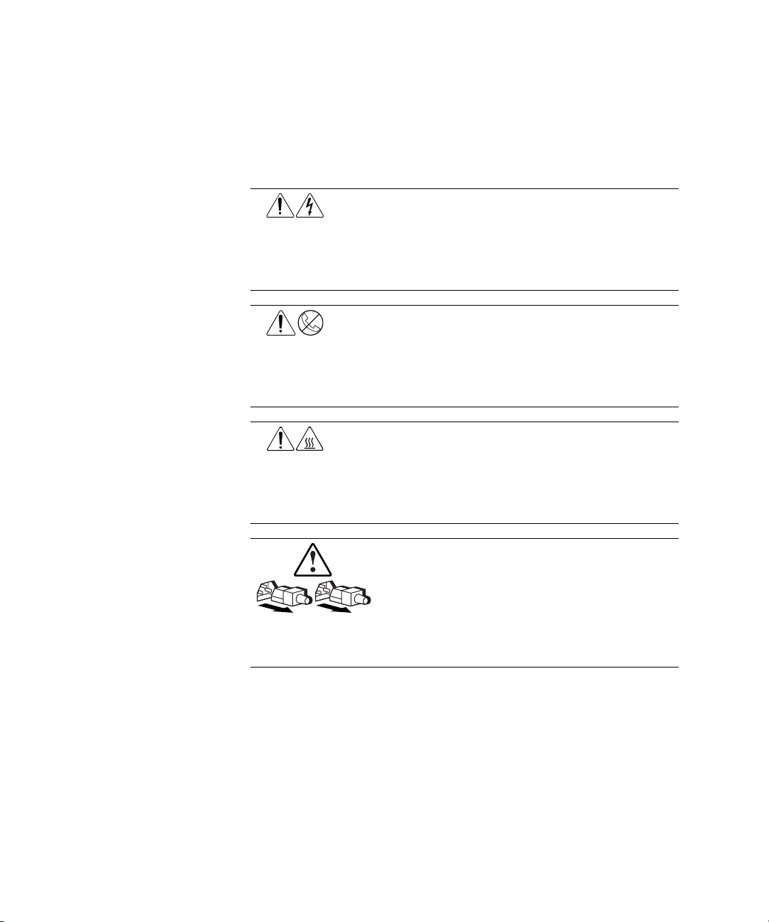
Any surface or area of the equipment marked with these symbols
indicates the presence of electrical shock hazards. Enclosed area
contains no operator serviceable parts.
WARNING: To reduce the risk of injury from electrical shock hazards,
do not open this enclosure.
Any RJ-45 receptacle marked with these symbols indicates a Network
Interface Connection.
WARNING: To reduce the risk of electrical shock, fire, or damage to
the equipment, do not plug telephone or telecommunications
connectors into this receptacle.
Any surface or area of the equipment marked with these symbols
indicates the presence of a hot surface or hot component. If this
surface is contacted, the potential for injury exists.
WARNING: To reduce the risk of injury from a hot component, allow
the surface to cool before touching.
Power Supplies or Systems marked with these symbols
indicate the equipment is supplied by multiple sources of
power.
WARNING: To reduce the risk of injury from electrical shock,
remove all power cords to completely disconnect power from
the system.
Page 7
Compaq Technician Notes
WARNING: Only authorized technicians trained by Compaq should attempt to repair this
equipment. All troubleshooting and repair procedures are detailed to allow only
subassembly/module level repair. Because of the complexity of the individual boards and
subassemblies, no one should attempt to make repairs at the component level or to make
modifications to any printed wiring board. Improper repairs can create a safety hazard. Any
indications of component replacement or printed wiring board modifications may void any
warranty.
WARNING: To reduce the risk of personal injury from electrical shock and hazardous energy
levels, do not exceed the level of repair specified in these procedures. Because of the
complexity of the individual boards and subassemblies, do not attempt to make repairs at the
component level or to make modifications to any printed wiring board. Improper repairs could
create conditions that are hazardous.
WARNING: To reduce the risk of electric shock or damage to the equipment:
■ If the system has multiple power supplies, disconnect power from the system by
unplugging all power cords from the power supplies.
■ Do not disable the power cord grounding plug. The grounding plug is an important safety
feature.
About This Guide vii
■ Plug the power cord into a grounded (earthed) electrical outlet that is easily accessible at
all times.
CAUTION: To properly ventilate your system, you must provide at least 12 inches (30.5 cm) of
clearance at the front and back of the computer.
CAUTION: The computer is designed to be electrically grounded. To ensure proper operation,
plug the AC power cord into a properly grounded AC outlet only.
Page 8

viii Compaq TFT5600 Rackmount Keyboard and Monitor (RKM) Maintenance and Service Guide
Where to Go for Additional Help
In addition to this guide, the following information sources are available:
■ User Documentation
■ Compaq Service Quick Reference Guide
■ Service Training Guides
■ Compaq Service Advisories and Bulletins
■ Compaq QuickFind
■ Compaq Insight Manager ™
■ Compaq Download Facility: Call 1-281-518-1418
Integrated Management Display
Some Compaq server models include a Compaq Integrated Management
Display (IMD), an integrated, 16x4 character display mounted on the front of
the server. This display provides easy-to-use menu-driven access to server
information, including model number, LCD firmware revision, and POST
operations.
Telephone Numbers
For the name of your nearest Compaq authorized reseller:
■ In the United States, call 1-800-345-1518.
■ In Canada, call 1-800-263-5868.
For Compaq technical support:
■ In the United States and Canada, call 1-800-386-2172.
■ For Compaq technical support phone numbers outside the United States
and Canada, visit the Compaq website:
www.compaq.com
Page 9

Chapter 1
Identifying Components
This chapter provides the illustrated parts breakdown and a serial number
location for the Compaq TFT5600 Rackmount Keyboard and Monitor (RKM).
Use the following information to locate and identify the components of the
TFT5600 Rackmount Keyboard and Monitor (RKM).
Page 10
1-2 Compaq TFT5600 Rackmount Keyboard and Monitor (RKM) Maintenance and Service Guide
Front Panel Components
1
2
3
4
5
17
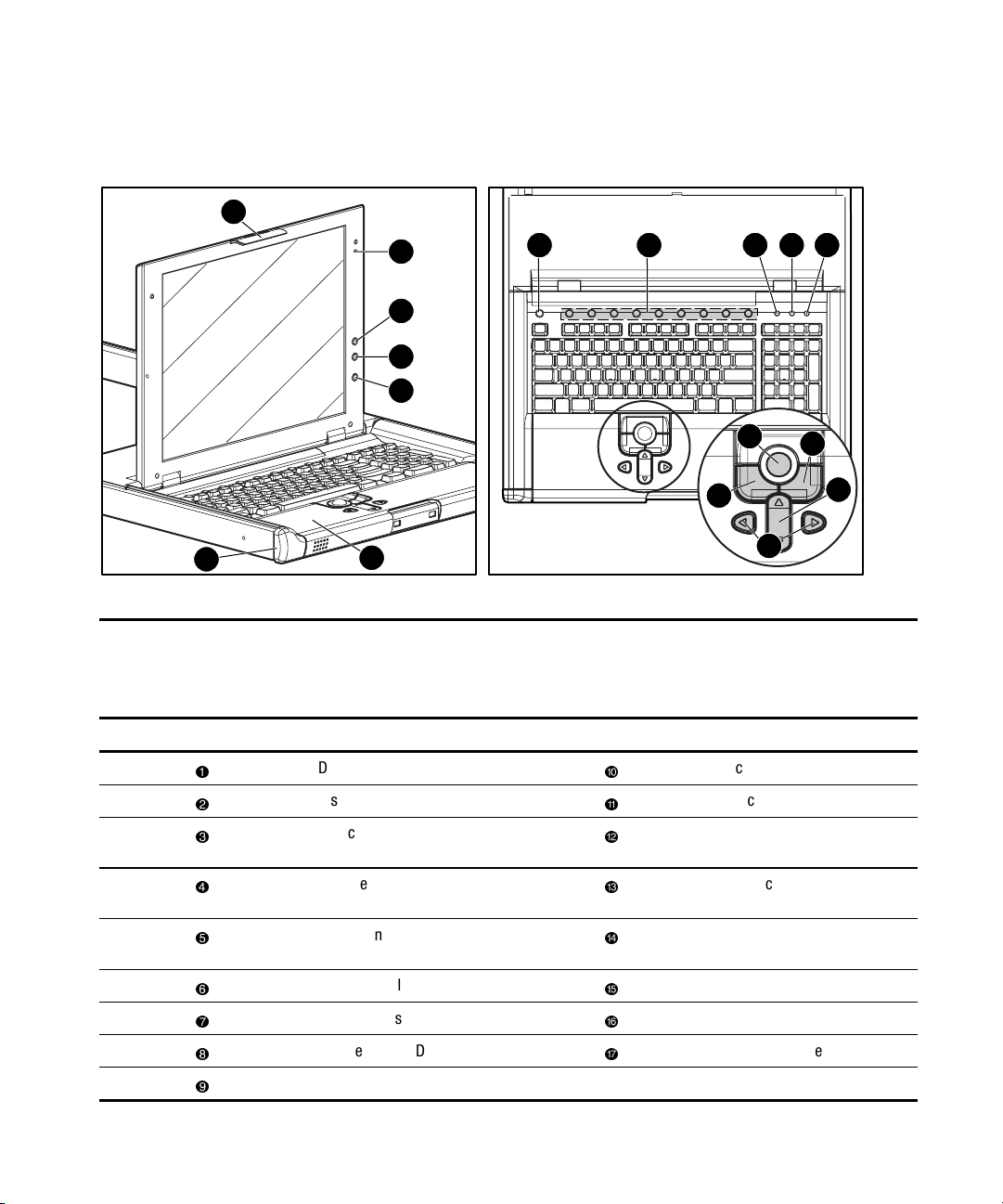
Figure 1-1. Identifying front panel components
16
6 7 8 9 10
11
13
15
Table 1-1
TFT5600 Rackmount Keyboard and Monitor (RKM)
Front Panel Components
Reference Component Reference Component
Display release latch
Display switch
On-screen display scroll up
button
Scroll lock LED
Track ball
Right pick button
12
14
On-screen display scroll
down button
On-screen display activation
button
Programmable wizard key
Nine hot keys
Number lock LED
Cap lock LED
Left pick button
Scroll up and down button
Scroll left and right button
Palm rest
Front plastic bezel
Page 11
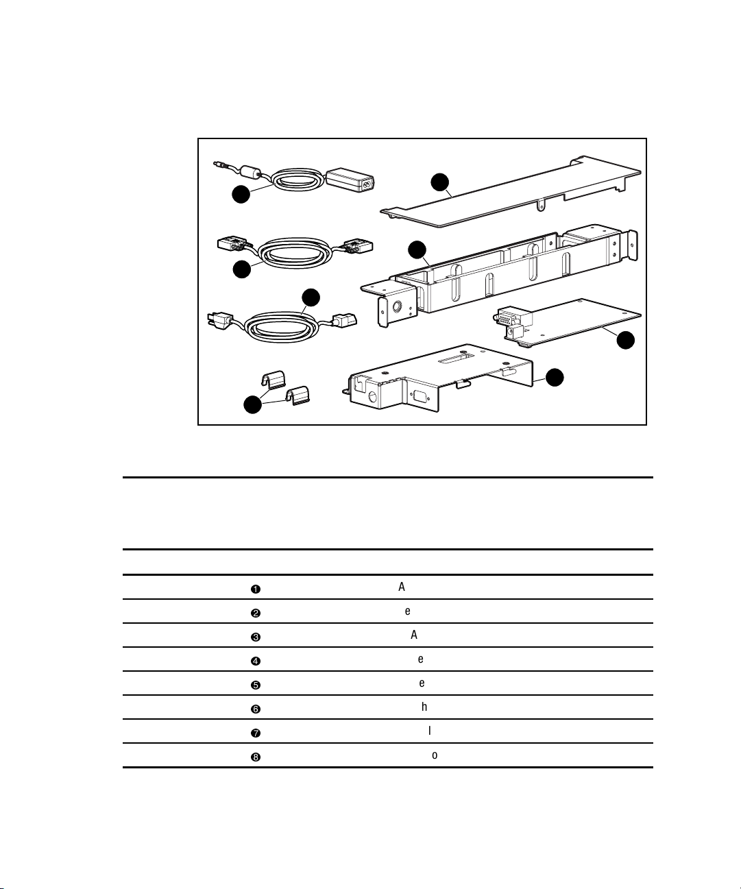
Rear Components
Identifying Components 1-3
1
3
4
6
Figure 1-2. Identifying rear components
Table 1-2
TFT5600 Rackmount Keyboard and Monitor (RKM)
Rear Components
Reference Component
2
5
7
8
AC brick
Rear cover
VGA cable
Power cord
Brace assembly
Clutch covers
Controller board
Metal controller cover
Page 12
1-4 Compaq TFT5600 Rackmount Keyboard and Monitor (RKM) Maintenance and Service Guide
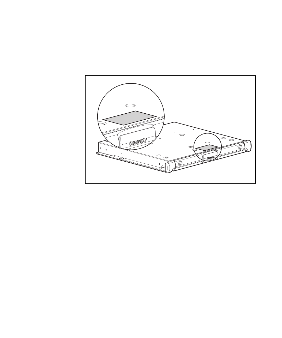
Serial Number Location
You will need to provide the TFT56000 RKM serial number to Compaq
whenever you request information or order spare parts. The serial number is
located on the bottom of the tray near the agency label.
Figure 1-3. Serial number location
Page 13

Chapter 2
Illustrated Spare Parts List
This chapter provides an illustrated parts breakdown and a spare parts list for
the Compaq TFT5600 Rackmount Keyboard and Monitor (RKM). See Table
2-1 for the names of referenced spare parts.
Page 14
2-2 Compaq TFT5600 Rackmount Keyboard and Monitor (RKM) Maintenance and Service Guide
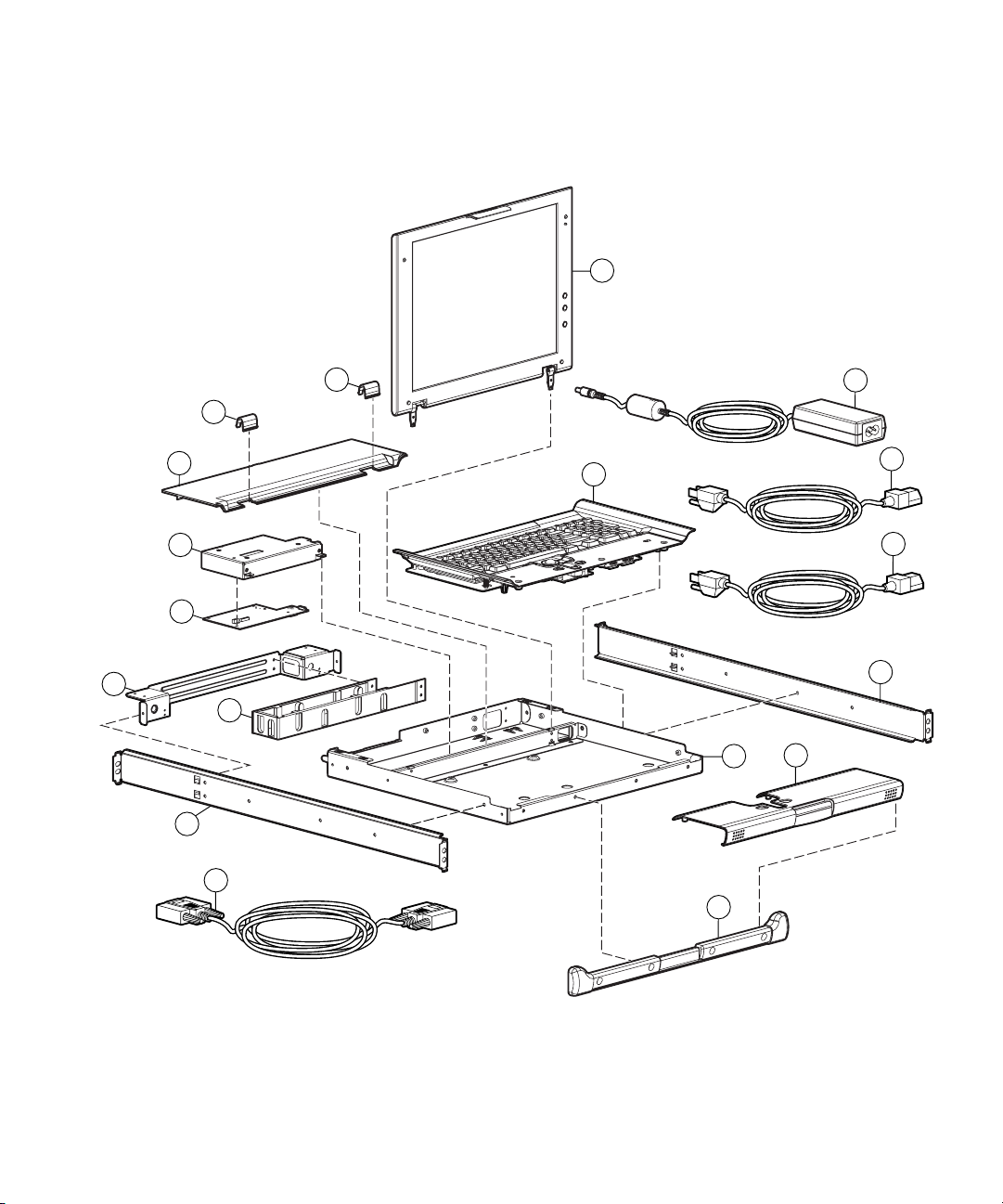
Exploded View of Spare Parts
1
2
2
2
4
5
3
3
3
6
10
4
2
2
7
8
9
3
Figure 2-1. Exploded view of the TFT5600 RKM
Page 15
Illustrated Spare Parts List 2-3
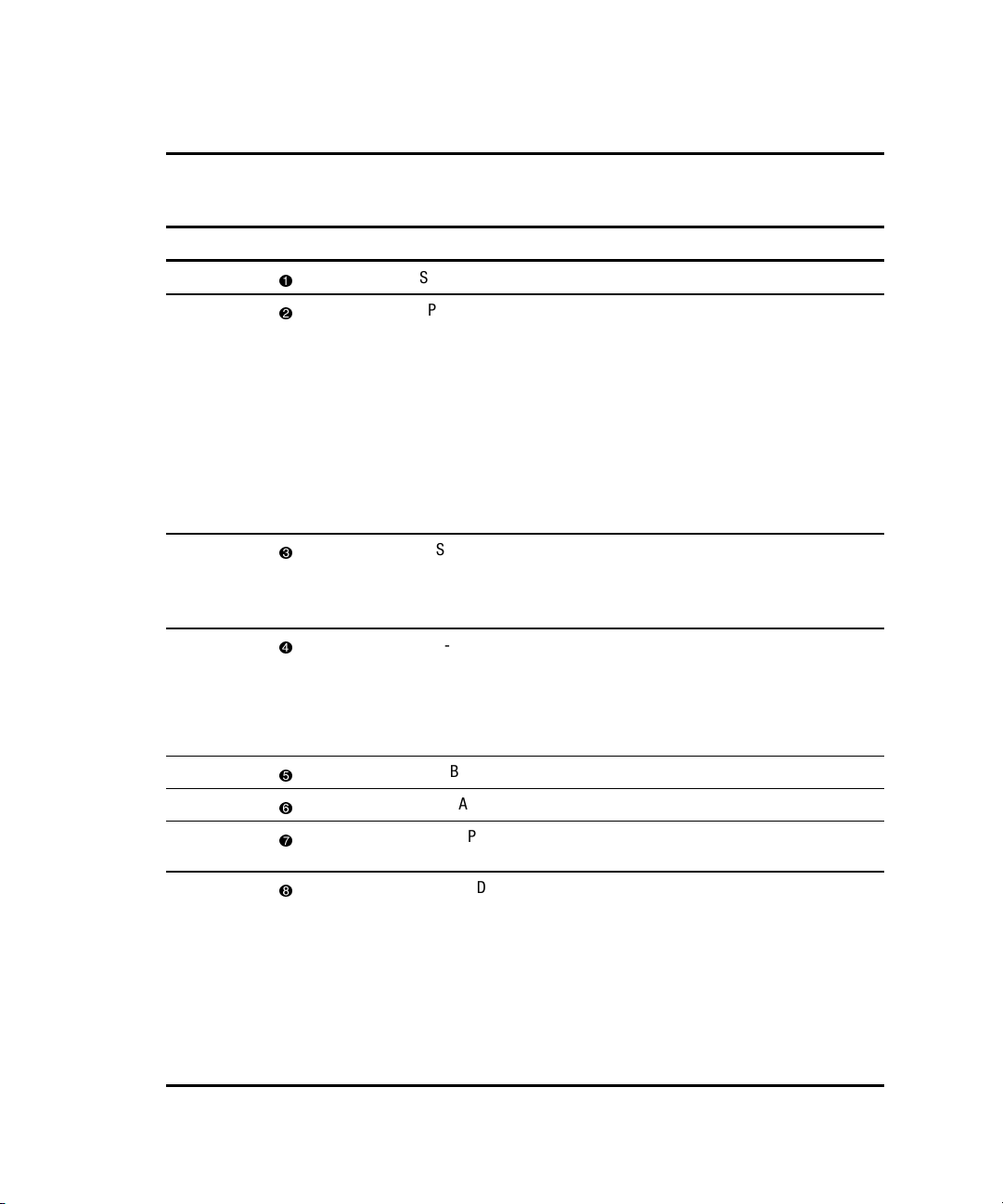
Table 2-1
TFT5600 Rackmount Keyboard and Monitor (RKM) Spare Parts List
Reference Description Spare Parts Number
SPS-DISPLAY,LCD,15” 229842-001
SPS-PLASTICS
■ BEZEL,TRAY,FRONT
229846-001
(224046-001)
■ REST,PALM
(222178-001)
■ COVER,REAR-TOP
(222179-001)
■ COVER,CLUTCH
(222180-001)
SPS-RAIL,MOUNTING,W/SLIDES
■ MOUNTING RAILS,W/SLIDES
■ BRACE,CMA
SPS-TRAY,METAL
■ TRAY, METAL
■ COVER, METAL
■ CLIP, GROUNDING
SPS-BD,CNTRLR 229847-001
SPS-CA,VGA,MALE-MALE,9FT 238729-001
SPS-ADPTRAC 40W
229845-001
229843-001
218319-001
4 PRONG/MINIJCK
SPS-CORD
SPS-CORD,AC,PWR,10’,BLK
SPS-CORD,AC,PWR,10’,BLK-EUR
SPS-CORD,AC,PWR,10’,BLK-UK
SPS-CORD,AC,PWR,10’,BLK-IT
SPS-CORD,AC,PWR,10’,BLK-SI
SPS-CORD,AC,PWR,10’,BLK-JP
255135-001
255135-021
255135-031
255135-061
255135-111
255135-291
continued
Page 16
2-4 Compaq TFT5600 Rackmount Keyboard and Monitor (RKM) Maintenance and Service Guide
Table 2-1
TFT5600 Rackmount Keyboard and Monitor (RKM) Spare Parts List
Reference Description Spare Parts Number
continued
SPS-CA,AC,LINE,C5C14,ADAPTER
SPS-KEYBOARD
SPS-KEYBOARD,CBN
SPS-KEYBOARD,CBN-UK
SPS-KEYBOARD,CBN-GR
SPS-KEYBOARD,CBN-FR
SPS-KEYBOARD,CBN-IT
SPS-KEYBOARD,CBN-SP
SPS-KEYBOARD,CBN-DK
SPS-KEYBOARD,CBN-NO
SPS-KEYBOARD,CBN-SE
SPS-KEYBOARD,CBN-SW
SPS-KEYBOARD,CBN-PT
SPS-KEYBOARD,CBN-BE
SPS-KEYBOARD,CBN-JP
SPS-KEYBOARD,CBN,INTL
192514-001
230978-001
230978-031
230978-041
230978-051
230978-061
230978-071
230978-081
230978-091
230978-101
230978-111
230978-131
230978-181
230978-291
230978-B31
Page 17

Chapter 3
Removal and Replacement
Preliminaries
IMPORTANT: Before beginning any of the procedures in Chapter 4, read and understand the cautions
and warnings in this chapter.
This chapter provides general service information for the Compaq TFT5600
Rackmount Keyboard and Monitor (RKM). Adherence to the procedures and
precautions described in this chapter are essential for proper service.
Page 18
3-2 Compaq TFT5600 Rackmount Keyboard and Monitor (RKM) Maintenance and Service Guide
Electrostatic
CAUTION: When the computer is plugged into an AC power source there is always voltage
applied to the system board. You must disconnect the power cord from the power source
before opening the computer to prevent system board or component damage.
Precautions
To prevent damage to the system, be aware of the precautions you need to
follow when setting up the unit or handling parts. A discharge of static
electricity from a finger or other conductor may damage system boards or
other static-sensitive devices. This type of damage may reduce the life
expectancy of the device.
To prevent electrostatic damage, observe the following precautions:
■ Avoid any contact by transporting and storing products in static-safe
containers.
■ Keep electrostatic-sensitive parts in their containers until they arrive at
static-free workstations.
■ Place parts on a grounded surface before removing them from their
containers.
■ Avoid touching pins, leads, or circuitry.
■ Make sure you are always properly grounded when touching a static-
sensitive component or assembly.
Grounding Methods
There are several methods for grounding. Use one or more of the following
methods when handling or installing electrostatic-sensitive parts:
■ Use a wrist strap connected by a ground cord to a grounded workstation
or computer chassis. Wrist straps are flexible straps with a minimum of
1 megohm
proper grounding, wear the strap snug against the skin.
■ Use heel straps, toe straps, or boot straps at standing workstations.
Wear the straps on both feet when standing on conductive floors or
dissipating floor mats.
■ Use conductive field service tools.
■ Use a portable field service kit with a folding static-dissipating work
mat.
± 10 percent resistance in the ground cords. To provide
Page 19
Rack Stability
Removal and Replacement Preliminaries 3-3
WARNING: To reduce the risk of personal injury or damage to the equipment,
be sure that:
■ The leveling jackets are extended to the floor.
■ The full weight of the rack rests on the leveling jacks.
■ The stabilizing feet are attached to the rack if it is a single-rack
installation.
■ The racks are coupled together in multiple-rack installations.
■ A rack may become unstable if more than one component is extended for
any reason. Extend only one component at a time.
Page 20

Chapter 4
Removal and Replacement Procedures
This chapter provides guidance for removing and replacing spare parts for the
Compaq TFT5600 Rackmount Keyboard and Monitor (RKM).
Before you begin any of these procedures, be sure to turn off the power to the
monitor, computer system, and other attached devices; then disconnect the
power cable from the power source.
CAUTION: As you disassemble the TFT5600 RKM, be sure to place the screws
in a safe place, and separate them according to their groupings.
After completing all necessary removal and replacement procedures, power on
the TFT5600 RKM to verify that all components are operating properly.
Page 21

4-2 Compaq TFT5600 Rackmount Keyboard and Monitor (RKM) Maintenance and Service Guide
Spare Replaceable Parts
The TFT5600 RKM contains the following replaceable parts:
■ SPS-PLASTICS 229846-001
G Clutch covers
G Rear cover
G Front plastic bezel
G Palm rest
■ SPS-KEYBOARD 230978-XXX
■ SPS-DISPLAY,LCD,15” 229842-001
■ SPS-BD,CNTRLR 229847-001
■ SPS-RAIL,MOUNTING,W/SLIDES 229845-001
G Mounting rails
G Slides
G Brace
G Cable management arm
■ SPS-TRAY,METAL 229843-001
G Metal tray
G Metal controller cover
G Metal grounding clip
■ SPS-ADPTRAC 40W 4PRONG/MINIJCK 218319-001
■ SPS-CORD,AC PWR,10’,BLK 255135-XXX
■ SPS-CA,VGA,MALE-MALE,9FT 238729-001
■ SPS-CA,AC LINE,C5-C14,ADAPTER 192514-001
Page 22

Product Kit Contents
■ M-6 cage nuts (2)
■ M-6 screws (8)
■ 6-32 screws (12)
■ Mounting rail and slides (2)
■ Cable management arm (1)
■ Brace (1)
■ TFT5600 Rackmount Keyboard Monitor (1)
G Model M5FAE, TFT5600 RKM
G Saleable Part Number 221546-001,-xxx
■ Lock plate (2)
■ Rack template (1)
■ Keyboard hot key label (2)
This kit may contain extra pieces of hardware for your convenience.
Removal and Replacement Procedures 4-3
Tools Required
■ Phillips screwdriver
■ T-15 Torx driver
Page 23

4-4 Compaq TFT5600 Rackmount Keyboard and Monitor (RKM) Maintenance and Service Guide
SPS-PLASTICS 229846-001
Figure 4-1. SPS-PLASTICS 229846-001
SPS-PLASTICS 229846-001
Reference Component
Table 4-1
Rear cover
Clutch covers
Front plastic bezel
Palm Rest
Page 24

Removing the Rear Cover
To remove the rear cover:
Removal and Replacement Procedures 4-5
Remove the screw
position
Figure 4-2. Removing screw and sliding rear cover off
.
IMPORTANT: When replacing the rear cover, make sure the plastic hooks, on the
underside of the rear cover, hook to the metal tray.
, slide the rear cover back , rotate and remove it out of
3
2
1
To replace the rear cover, reverse the above procedure.
Page 25

4-6 Compaq TFT5600 Rackmount Keyboard and Monitor (RKM) Maintenance and Service Guide
Removing the Clutch Covers
To remove the clutch covers:
Unsnap the clutch covers, rotate them toward the front of the unit, and remove
them.
Figure 4-3. Removing clutch covers
IMPORTANT: Before replacing the clutch covers, the rear cover must be installed and the
cables must be aligned properly so there is no interference.
To replace the clutch covers, reverse the above procedure.
Page 26

Removing the Palm Rest
To remove the palm rest:
Removal and Replacement Procedures 4-7
Turn the unit over and remove the four screws
the palm rest up and out
Figure 4-4. Removing screws securing palm rest
IMPORTANT: Before replacing the palm rest, the front plastic bezel must be installed.
, and remove it .
1
securing the palm rest, slide
3
2
2
1
1
To replace the palm rest, reverse the above procedure.
Page 27

4-8 Compaq TFT5600 Rackmount Keyboard and Monitor (RKM) Maintenance and Service Guide
Removing the Front Plastic Bezel
IMPORTANT: You must remove the palm rest before you remove the front plastic bezel.
To remove the front plastic bezel:
Remove the four screws securing the front plastic bezel to the metal tray; then
remove the front plastic bezel.
Figure 4-5. Removing screws from front plastic bezel
To replace the front plastic bezel, reverse the above procedure.
Page 28

SPS-KEYBOARD 230978-XXX
Removal and Replacement Procedures 4-9
Figure 4-6. SPS-KEYBOARD 230978-XXX
Page 29

4-10 Compaq TFT5600 Rackmount Keyboard and Monitor (RKM) Maintenance and Service Guide
Removing the Keyboard Assembly
IMPORTANT: You must remove the clutch covers, rear cover, and AC brick before you
remove the keyboard assembly.
To remove the keyboard assembly:
1. Disconnect all cables from their source.
2. Turn the unit over and remove the four screws securing the palm rest
and the five screws securing the keyboard assembly to the metal tray.
Figure 4-7. Removing screws from bottom of unit
Page 30

Removal and Replacement Procedures 4-11
3. Turn the unit right side up and remove the palm rest by sliding the palm
rest up and out.
Figure 4-8. Removing palm rest
Page 31

4-12 Compaq TFT5600 Rackmount Keyboard and Monitor (RKM) Maintenance and Service Guide
IMPORTANT: Before removing the keyboard assembly, the tie wraps holding the cables
together in the rear of the unit must be cut.
4. Remove the keyboard assembly, paying special attention to the cord in
the rear.
Figure 4-9. Removing keyboard assembly
To replace the keyboard assembly, reverse the above procedure.
Page 32

SPS-DISPLAY,LCD,15” 229842-001
Removal and Replacement Procedures 4-13
Figure 4-10. SPS-DISPLAY,LCD,15” 229842-001
Page 33

4-14 Compaq TFT5600 Rackmount Keyboard and Monitor (RKM) Maintenance and Service Guide
Removing the Display
IMPORTANT: You must remove the clutch covers, rear cover, keyboard assembly, and
palm rest before you remove the display.
To remove the display:
1. Remove the screw securing the grounding clip and cable to the metal
controller cover.
Figure 4-11. Removing grounding clip
Page 34

Removal and Replacement Procedures 4-15
2. Unplug the three cables connecting the display assembly to the
controller board.
WARNING: Do not pull on the exposed wires, only pull on the plastic shroud
connectors attached to the wires.
Figure 4-12. Disconnecting cables connecting display assembly
Page 35

4-16 Compaq TFT5600 Rackmount Keyboard and Monitor (RKM) Maintenance and Service Guide
3. Remove the four screws
remove the display
Figure 4-13. Removing screws securing display
securing the display to the metal tray; then
.
2
1
To replace the display, reverse the above procedure.
1
Page 36

Removal and Replacement Procedures 4-17
SPS-ADPTRAC 40W 4PRONG/MINIJCK 218319-001
Figure 4-14. SPS-ADPTRAC 40W 4PRONG/MINIJCK 218319-001
Page 37

4-18 Compaq TFT5600 Rackmount Keyboard and Monitor (RKM) Maintenance and Service Guide
Removing the AC Brick
IMPORTANT: You must remove the rear cover before you remove the AC brick.
To remove the AC brick:
1. Disconnect all cables from their source.
2. Unplug the AC brick from the controller board and lift the brick off of
the Velcro.
Figure 4-15. Removing AC brick
IMPORTANT: Make sure the AC brick is properly located on the Velcro so that the rear
cover can be installed.
To replace the AC brick, reverse the above procedure.
Page 38

SPS-BD,CNTRLR 229847-001
Removal and Replacement Procedures 4-19
Figure 4-16. SPS-BD,CNTRLR 229847-001
Page 39

4-20 Compaq TFT5600 Rackmount Keyboard and Monitor (RKM) Maintenance and Service Guide
Removing the Controller Board
IMPORTANT: You must remove the rear cover and AC brick before you remove the
controller board.
To remove the controller board:
1. Remove the screw securing the grounding clip to the metal controller
cover.
2. Disconnect all cables from their source, except for the VGA cable.
3. Remove the two screws securing the metal controller cover to the metal
tray.
Figure 4-17. Removing screws from metal controller cover
Page 40

Removal and Replacement Procedures 4-21
4. Slide the metal controller cover
Figure 4-18. Removing metal controller cover
and lift it straight out .
1
2
Page 41

4-22 Compaq TFT5600 Rackmount Keyboard and Monitor (RKM) Maintenance and Service Guide
5. Unscrew the VGA cable.
6. Remove the two screw locks from the VGA cable connector.
Figure 4-19. Removing screw locks
Page 42

Removal and Replacement Procedures 4-23
7. Remove the three screws securing the controller board to the metal
controller cover.
Figure 4-20. Removing screws from metal controller cover
8. Remove the controller board from the metal controller cover.
To replace the controller board, reverse the above procedure.
Page 43

4-24 Compaq TFT5600 Rackmount Keyboard and Monitor (RKM) Maintenance and Service Guide
SPS-RAIL,MOUNTING,W/SLIDES 229845-001
Figure 4-21. SPS-RAIL,MOUNTING,W/SLIDES 229845-001
Table 4-2
SPS-RAIL,MOUNTING,W/SLIDES 229845-001
Reference Component
Mounting rails
Slides
Brace assembly
Page 44

Removing the Brace Assembly
To remove the brace assembly:
1. Disconnect all cables from their source.
2. Unthread the cables from the cable management arm.
3. Remove the two screws securing the cable management arm to the rear
of the metal tray.
Removal and Replacement Procedures 4-25
Figure 4-22. Removing screws securing brace assembly
Page 45

4-26 Compaq TFT5600 Rackmount Keyboard and Monitor (RKM) Maintenance and Service Guide
4. Remove the two screws
rack, and remove the brace assembly
Figure 4-23. Removing screws securing brace assembly
securing the brace assembly to the rear of the
.
2
1
1
To replace the brace assembly, reverse the above procedure.
Page 46

Removing the Mounting Rails with Slides
IMPORTANT: You must remove the unit before you remove the mounting rails with
slides.
To remove mounting rails with slides:
1. Remove the two screws, on each side of the mounting rails, securing
them to the brace assembly.
2. Remove the brace assembly.
3. Remove mounting rail screws from the front of the rack.
Removal and Replacement Procedures 4-27
Figure 4-24. Removing front mounting rail screws
Page 47

4-28 Compaq TFT5600 Rackmount Keyboard and Monitor (RKM) Maintenance and Service Guide
4. Remove the screw
1
Figure 4-25. Removing mounting rails from rear of rack
and mounting rails from the rear of the rack.
2
5. Remove the mounting rails with slides.
To replace the mounting rails with slides, reverse the above procedure.
Page 48

SPS-TRAY,METAL 229843-001
Removal and Replacement Procedures 4-29
Figure 4-26. SPS-TRAY,METAL 229843-001
Table 4-3
SPS-TRAY,METAL 229843-001
Reference Component
Metal tray
Metal controller cover
Metal grounding clip (not shown)
Page 49

4-30 Compaq TFT5600 Rackmount Keyboard and Monitor (RKM) Maintenance and Service Guide
Removing the Metal Controller Cover
IMPORTANT: You must remove the clutch covers, rear cover, and AC brick before you
remove the metal controller cover.
To remove the metal controller cover:
1. Remove the screw securing the grounding clip to the metal controller
cover.
2. Disconnect all cables from their source, except for the VGA cable.
3. Remove the two screws securing the metal controller cover to the metal
tray.
Figure 4-27. Removing screws from metal controller cover
Page 50

Removal and Replacement Procedures 4-31
4. Slide the metal controller cover
Figure 4-28. Removing metal controller cover
and lift straight out .
2
1
5. Unscrew the VGA cable.
6. Remove the two screw locks from the VGA cable connector.
7. Remove the three screws securing the controller board to the metal
controller cover.
8. Remove the controller board from the metal controller cover.
To replace the metal controller cover, reverse the above procedure.
Page 51

4-32 Compaq TFT5600 Rackmount Keyboard and Monitor (RKM) Maintenance and Service Guide
Removing the Metal Tray
IMPORTANT: You must remove the clutch covers, rear cover, and metal controller cover
before removing the metal tray.
To remove the metal tray:
1. Disconnect all cables from their source.
2. Turn the unit over and remove the nine screws from the bottom of the
unit.
Figure 4-29. Removing screws from bottom of unit
Page 52

Removal and Replacement Procedures 4-33
3. Remove the palm rest.
4. Turn the unit right side up and lift the keyboard assembly straight out,
paying special attention to the cord in the rear.
Figure 4-30. Removing keyboard assembly
Page 53

4-34 Compaq TFT5600 Rackmount Keyboard and Monitor (RKM) Maintenance and Service Guide
5. Remove the front plastic bezel.
6. Remove the four screws
the display out
Figure 4-31. Removing screws and lifting out monitor assembly
securing the display to the metal tray and lift
.
2
1
To replace the metal tray, reverse the above procedure.
1
Page 54

SPS-CA,VGA,MALE-MALE,9FT 238729-001
Removal and Replacement Procedures 4-35
Figure 4-32. SPS-CA,VGA,MALE-MALE,9FT 238729-001
Page 55

Specifications
Table 5-1
TFT5600 RKM Specifications
Chapter 5
Display
Type
Viewable Image Size
Face Treatment
Maximum Weight
(Unpacked)
Maximum Dimensions
Height 1.7 in 4.32 cm
Depth 15.6 in 39.6 cm
Width 17.00 in 43.2 cm
15-in
Flat panel, Active matrix-TFT LCD
15-in diagonal 38.1 cm
Transparent protector with antiglare
coating
13.75 lb 6.25 kg
38.1 cm
continued
Page 56

5-2 Compaq TFT5600 Rackmount Keyboard and Monitor (RKM) Maintenance and Service
Table 5-1
TFT5600 RKM Specifications
Maximum Graphics
Resolution
continued
1024 x 768 @ 60Hz Refresh Rate
Horizontal Frequency
Vertical Frequency
Environmental Temperature Requirements (Independent of Altitude)
Operating
Storage Temperature
Humidity (Non-Condensing)
Operating
Non-Operating
Power Source
Power Consumption
48.2 kHz
60 Hz
10 to 50°C
0 to 60°C
20 to 90%
0 to 90%
90 to 264 VAC, 47 to 63 Hz
50 Watts
Page 57

Index
A
AC brick
photograph 4-17
rear components 1-3
replacing 4-18
agency label, serial number
location 1-4
B
bezel, removing front plastic 4-8
boot straps, grounding
methods 3-2
brace assembly
photograph 4-24
rear components 1-3
removing 4-25
replacing 4-26
buttons
left pick 1-2
nine hot keys 1-2
on-screen display
activation 1-2
scroll down 1-2
scroll up 1-2
programmable wizard key 1-2
right pick 1-2
scroll left and right 1-2
scroll up and down 1-2
C
cable management arm
photograph 4-24
removing 4-25
cap lock LED 1-2
cautions See also warnings
electrostatic 3-2
grounding vii
overheating vii
retaining hardware 4-1
symbols in text v
ventilation clearances vii
clutch covers
photograph 4-4
rear components 1-3
removing 4-6
replacing 4-6
Compaq
Download Facility, telephone
number viii
legal notice ii
technician notes vii
components, identifying 1-1
conductive
field service tools 3-2
floors 3-2
Page 58

2 Compaq TFT5600 Rackmount Keyboard and Monitor (RKM) Maintenanace and Service Guide
controller board
photograph 4-19
rear components 1-3
removing 4-20
replacing 4-23
D
dimensions 5-1
display
photograph 4-13
release latch 1-2
replacing 4-16
switch 1-2
dissipating floor mats 3-2
E
electrostatic
precautions 3-2
preventing 3-2
exploded view of spare parts 2-2
F
features
front panel components 1-2
rear components 1-3
frequency, horizontal and
vertical 5-2
front panel components 1-2
button
left pick 1-2
right pick 1-2
cap lock LED 1-2
display
release latch 1-2
switch 1-2
front plastic bezel 1-2
nine hot keys 1-2
on-screen display
activation button 1-2
scroll down button 1-2
scroll up button 1-2
programmable wizard key 1-2
scroll
left and right button 1-2
lock LED 1-2
up and down button 1-2
track ball 1-2
front plastic bezel 1-2
photograph 4-4
removing 4-8
replacing 4-8
H
heel straps, grounding
methods 3-2
help
additional sources viii
Compaq authorized resellers,
telephone numbers viii
Compaq website viii
technical support telephone
numbers viii
horizontal frequency 5-2
humidity 5-2
I
icons, symbols on equipment vi
illustrated spare parts list 2-1
illustrations
disconnecting cables 4-15
exploded view of TFT5600
RKM 2-2
identifying
front panel components 1-2
rear components 1-3
removing
AC brick 4-18
clutch covers 4-6
grounding clip 4-14
keyboard assembly 4-12, 4-33
metal controller cover 4-21,
4-31
mounting rail brackets from rear
of rack 4-28
mounting rails with slides 4-27
palm rest 4-7, 4-11
Page 59

Index 3
screw and slding rear cover 4-5
screw locks 4-22
screws and lifting out monitor
assembly 4-34
screws from bottom of
unit 4-10, 4-32
screws from front plastic
bezel 4-8
screws from metal controller
cover 4-20, 4-23, 4-30
screws securing brace
assembly 4-25, 4-26
screws securing the
display 4-16
serial number location 1-4
image
size 5-1
IMD (Integrated Management
Display)
description viii
important See also notes
before beginning
procedures 3-1
before removing
AC brick 4-18
controller board 4-20
display 4-14
front plastic bezel 4-8
keyboard 4-10
keyboard assembly 4-12
metal controller cover 4-30
metal tray 4-32
mounting rails with slides 4-27
before replacing
clutch covers 4-6
palm rest 4-7
rear cover 4-5
symbols in text v
installing
AC brick 4-18
brace assembly 4-26
controller board 4-23
display 4-16
front plastic bezel 4-7
keyboard 4-12
metal controller cover 4-32
metal tray 4-34
mounting rails with
slides 4-28
palm rest 4-8
K
keyboard
photograph 4-9
removing 4-10
replacing 4-12
L
latch, display release 1-2
LED
cap lock 1-2
scroll lock 1-2
left pick button 1-2
legal notice ii
M
metal controller cover
photograph 4-29
rear components 1-3
removing 4-30
replacing 4-32
metal tray
photograph 4-29
removing 4-32
replacing 4-34
spare kit
metal controller cover 4-2
metal tray 4-2
Page 60

4 Compaq TFT5600 Rackmount Keyboard and Monitor (RKM) Maintenanace and Service Guide
mounting rails with slides
photograph 4-24
removing 4-27
replacing 4-28
N
nine hot keys 1-2
notes See also important
symbols in text v
O
on-screen display
activation button 1-2
scroll down button 1-2
scroll up button 1-2
P
palm rest
photograph 4-4
removing 4-7
replacing 4-7, 4-8
photographs
AC brick 4-17
controller board 4-19
display 4-13
keyboard 4-9
metal tray 4-29
mounting rails with
slides 4-24
plastics 4-4
VGA cable 4-35
plastics spare kit
clutch covers 4-2
front plastic bezel 4-2
palm rest 4-2
rear cover 4-2
removing 4-4
portable field service kit 3-2
power cord, rear components 1-3
product kit contents 4-3
programmable wizard key 1-2
R
rack stability 3-3
rails and slides spare kit
brace assembly 4-2
cable management arm 4-2
mounting rails 4-2
removing 4-24
slides 4-2
rear components 1-3
AC brick 1-3
brace assembly 1-3
clutch covers 1-3
controller board 1-3
metal controller cover 1-3
power cord 1-3
rear cover 1-3
VGA cable 1-3
rear cover
installing 4-6
photograph 4-4
rear components 1-3
removing 4-5
removal and replacement
preliminaries 3-1
procedures 4-1
removing
AC brick 4-18
brace assembly 4-25
clutch covers 4-6
controller board 4-20
display 4-14
front plastic bezel 4-8
keyboard 4-10
metal controller cover 4-30
metal tray 4-32
mounting rails with
slides 4-27
palm rest 4-7
rear cover 4-5
Page 61

Index 5
replacing
AC brick 4-18
brace assembly 4-26
clutch covers 4-6
controller board 4-23
display 4-16
keyboard assembly 4-12
metal controller cover 4-32
metal tray 4-34
mounting rails with
slides 4-28
palm rest 4-7, 4-8
right pick button 1-2
RJ-45 receptacle vi
S
scroll
left and right button 1-2
lock LED 1-2
up and down button 1-2
serial number location 1-4
spare replaceable parts 4-2
specifications 5-1
display 5-1
environmental
temperature 5-2
face treatment 5-1
horizontal frequency 5-2
humidity 5-2
maximum dimensions 5-1
maximum graphic
resolution 5-2
maximum weight 5-1
power consumption 5-2
power source 5-2
vertical frequency 5-2
viewable image size 5-1
symbols
in text v
on equipment vi
T
tables
front panel components 1-2
metal tray 4-29
mounting rails with
slides 4-24
plastics 4-4
rear components 1-3
spare parts list 2-3
specifications 5-1
technical support
Compaq website viii
telephone numbers viii
technician notes vii
telephone numbers
Compaq authorized
resellers viii
Compaq Download
Facility viii
technical support viii
temperature
operating 5-2
storage 5-2
TFT5600 RKM
brace assembly 2-3
cable management arm 2-3
front panel components 1-2
rails 2-3
rear components 1-3
slides 2-3
spare parts list 2-3
toe straps, grounding methods 3-2
tools required 4-3
trackball 1-2
V
vertical frequency 5-2
VGA cable
photograph 4-35
rear components 1-3
removing 4-22
Page 62

6 Compaq TFT5600 Rackmount Keyboard and Monitor (RKM) Maintenanace and Service Guide
W
warnings See also cautions
component level repairs vii
electrical shock v, vi
equipment damage vii
exposed wires 4-15
grounding plug vi, vii
hazardous energy levels vii
hot surface vi
improper repairs vii
multiple sources of power vi
personal injury v, vii
rack stability 3-3
symbols in text v
voiding warranty vii
weight 5-1
wrist straps, grounding
methods 3-2
www.compaq.com viii
 Loading...