

Page 1

HP NetServer LH 3r
Installation Guide
for
Compaq® 4000/7000 Racks
HP Part Number 5967-5208
Printed in July 1998
Page 2

Notice
The information contained in this document is subject to change without notice.
Hewlett-Packard makes no warranty of any kind with regard to this
material, including, but not limited to, the implied warranties of
merchantability and fitness for a particular purpose. Hewlett-Packard shall
not be liable for errors contained herein or for incidental or consequential
damages in connection with the furnishing, performance, or use of this material.
Hewlett-Packard assumes no responsibility for the use or reliability of its software
on equipment that is not furnished by Hewlett-Packard.
This document contains proprietary information that is protected by copyright.
All rights are reserved. No part of this document may be photocopied,
reproduced, or translated to another language without the prior written consent of
Hewlett-Packard Company.
Compaq is a registered trademark of Compaq Computer Corporation.
APC is a registered trademark of American Power Conversion Corp.
Hewlett-Packard Company
Network Server Division
Technical Marketing / MS 49EU-FQ
5301 Stevens Creek Boulevard
P.O. Box 58059
Santa Clara, CA 95052-8059 USA
© Copyright 1998, Hewlett-Packard Company.
Audience Assumptions
The user guide is for the person who installs, administers, and troubleshoots
network servers. Hewlett-Packard Company assumes you are qualified in the
servicing of computer equipment and trained in recognizing hazards in products
with hazardous energy levels.
ii
Page 3

Contents
1 Introduction ................................................................................................. 1
HP NetServer LH 3r – Compaq Rack Precautions......................................... 4
2 Overview ......................................................................................................5
3 Installation ................................................................................................... 7
Preparation.................................................................................................... 7
Marking the Installation Holes.................................................................... 7
Installing the Bar Nuts, Screws, and Rack Nuts......................................... 9
Mounting the Slides.................................................................................10
Installing the NetServer...............................................................................11
Installing the Recessed Mounting Brackets.................................................. 14
4 Warranty and Support............................................................................... 17
HP Repair and Telephone Support.............................................................. 18
Index............................................................................................................... 19
iii
Page 4

Page 5
1 Introduction
This document describes how to mount an HP NetServer LH 3r into a Compaq
model 4000- or 7000-series rack enclosure. Refer to the HP NetServer LH 3r
Road Map and the HP NetServer LH 3/3r User Guide that came with the
NetServer for instructions on adding accessories to and configuring the
NetServer.
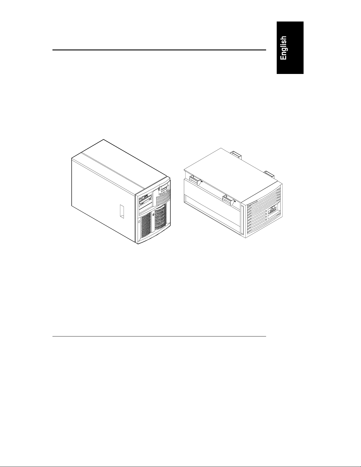
The HP NetServer LH 3 (the pedestal version of this NetServer) cannot be
installed in a rack enclosure. If you want to convert an LH 3 to an LH 3r for
installation in a rack enclosure, contact your HP Reseller for information about
the available conversion kit (HP NetServer LH 3 Pedestal-to-Rack Conversion
Kit). The HP NetServer LH 3 and LH 3r are shown in Figure 1-1.
®
LH 3r (Rack-Optimized)LH 3 (Pedestal)
Figure 1-1. Versions of the NetServer LH 3
1
Page 6

Chapter 1 Introduction
WARNING To prevent the rack from tipping over and causing equipment
damage or bodily injury, be sure that the stabilizing, anti-tip
feature is installed on this rack enclosure (see Figure 1-2).
WARNING To prevent the rack from tipping over and causing equipment
damage or bodily injury, do not extend more than one piece
of equipment at a time out of the front of the rack enclosure.
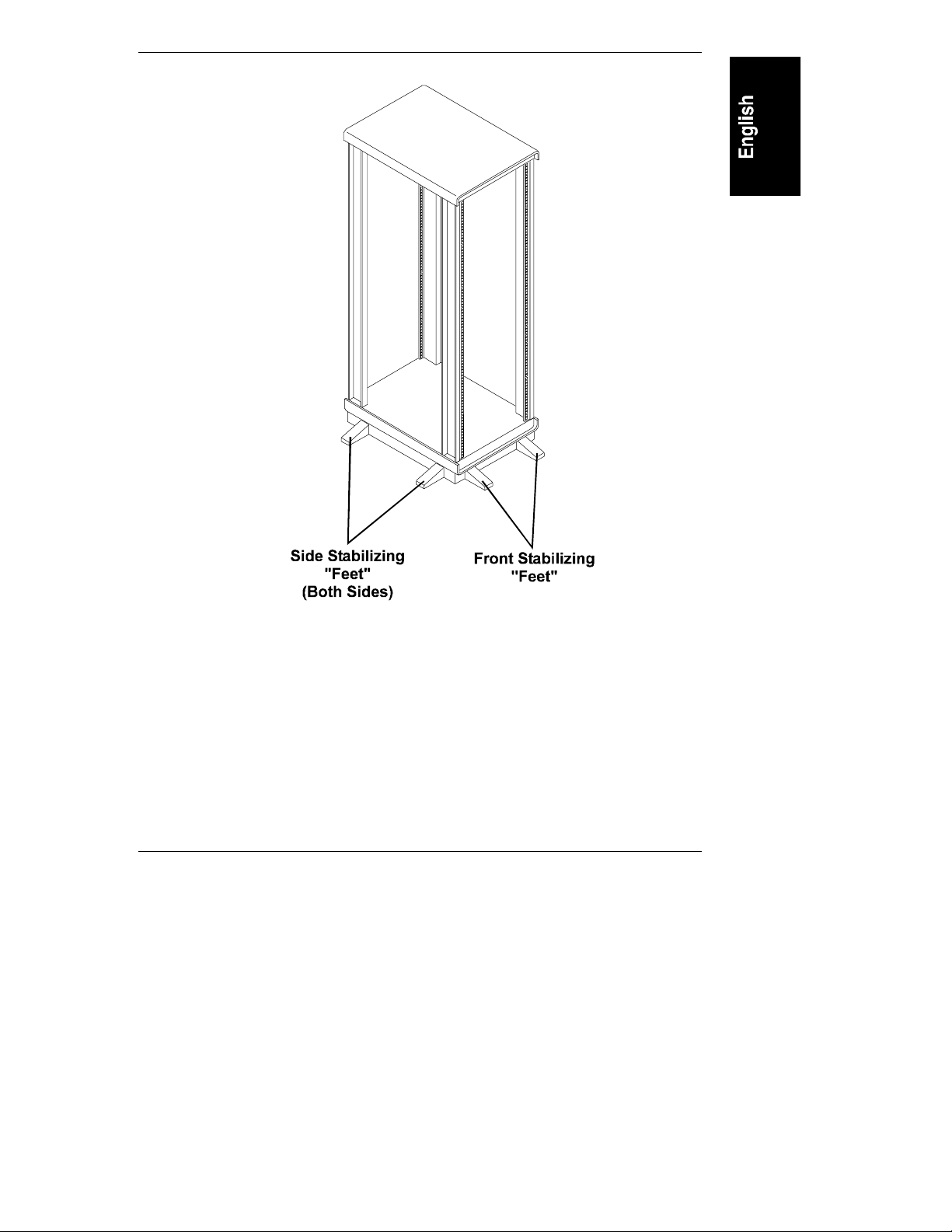
Be sure that the stabilizing, anti-tip feature is installed on the rack enclosure in
which you are installing the HP NetServer LH 3r. This option consists of two
"feet" at the front of the base of the enclosure and, if you are installing this
NetServer in a single rack enclosure, two "feet" each on the left and right sides of
the enclosure (see Figure 1-2).
2
Page 7
Chapter 1 Introduction
Figure 1-2. Single Rack Enclosure With the Anti-Tip Stabilizing
Feature Installed
3
Page 8

Chapter 1 Introduction
HP NetServer LH 3r – Compaq Rack Precautions
CAUTION If this NetServer is not installed according to these
instructions, damage to the NetServer or accessories may
result. Damage due to improper installation is not covered by
the HP Warranty. Observe the precautions listed in this
section to maintain the NetServer’s reliability.
When the HP NetServer LH 3r is installed in a Compaq rack enclosure, certain
requirements must be addressed to assure that the needs of the NetServer are met.
This NetServer will meet the requirements designed for the NetServer if:
• The NetServer is installed in a Compaq model 4000- or 7000-series rack
enclosure. This NetServer is not supported in any other non-HP rack
enclosure.
• If you choose to use a door on this enclosure, only a Compaq model 4000-
or 7000-series door may be used. No other door may be used. The
enclosure may be used with the door open, closed, or removed.
• Mass storage devices listed in the Tested Products List (located on the
HP NetServer Navigator CD-ROM) are used exclusively in the NetServer.
• Use HP rack accessories. (Note that HP rack accessories are not optimized
for Compaq rack enclosures.)
Compaq rack accessories have not been tested with HP NetServer
products, but components such as monitors, keyboards, switchboxes, and
PDUs often work.
• Use APC
APC offers mounting kits for Compaq rack enclosures.
This NetServer is not supported in a rack enclosure under circumstances other
than those listed above.
See the "Warranty and Support" section of this document for additional support
considerations.
4
®
uninterruptible power supplies (UPS) with HP NetServers.
Page 9

2Overview
The steps required to install the NetServer in the rack are summarized below:
NOTE This is only a summary; detailed instructions are provided on the
following pages.
• Measure and mark the appropriate holes on all four rack columns
• Install one bar nut on each of the four rack columns
• Insert two rack nuts on each of the two front columns only
• Attach the slides to the columns
• Extend the slides
• Remove power supply modules and hot-swap drives from the NetServer
• Lift the NetServer onto the slides
• Secure the NetServer to the slides
• Remove the lifting handles from the NetServer
• Install the power supply modules and hot-swap drives in the NetServer
• Push the NetServer back into the chassis
• Install the recessed mounting brackets on the two front columns only
5
Page 10

Chapter 2 Overview
Terms used in this document are defined in the table below.
Term
Definition
Bar nut Short, threaded bar used behind slide mounting flanges.
Used in place of individual nuts to mate with slide
mounting screws.
Rack nut Single nut designed to clip behind the rack column and
accept a screw through the hole in the column.
Slide Extendible side bracket which is attached to the rack
chassis columns on which the NetServer is mounted.
Consists of stationary component, and an extendible
member (see Figure 3-3). Allows access to the NetServer
after it is installed in the rack chassis.
Slide mounting flange Mounting flange located at either end of the slide (see
Figure 3-3).
Rack (rack chassis,
rack enclosure)
Recessed mounting
brackets
The equipment enclosure in which the NetServer will be
installed.
Two brackets (one tall, one short) that attach to the front of
the NetServer and the front rack columns to hold the
NetServer in the closed position.
EIA unit Industry standard measurement (1.75 inches / 44.45 mm),
consisting of four vertical mounting holes in a rack
column.
6
Page 11

3 Installation
This section contains detailed instructions for installing an HP NetServer LH 3r
in certain models of Compaq rack enclosures.
Preparation
Before beginning the installation of the NetServer into the rack, you must prepare
the rack and the NetServer.
Determine the location at which the NetServer is to be installed in the rack
enclosure. Mark the bottom and top of this location on the rack columns. The HP
NetServer LH 3r measures 8 EIA units tall.
Marking the I nstallation Holes
You will mark two holes on each of the four columns to use for the bar nuts and
screws that hold the slide to the column.
When marking the holes, mark the outer surface of the column (see Figure 3-1);
on the front columns, this is the column surface facing forward; on the rear
columns, this is the surface facing rearward. Use tape or a marker pen to mark
the appropriate holes on each column.
To mark the slide mounting holes (refer to Figure 3-1):
1. Count up from the top of the unit below, marking the 20th and 22nd
holes.
2. Repeat for all four columns.
NOTE Do not place nuts or screws in the holes, only mark them.
7
Page 12

Chapter 3 Installation
22nd
20th
22nd
20th
(At Rear
Of Column)
22nd
20th
15th
11th
22nd
19th
20th
14th
Figure 3-1. Marking Holes for Installation
You will mark two holes on each o f the fro nt c olumns to u s e fo r the rac k nuts where
the two recessed mounting bracke ts attach to the columns. W he n the installation is
complete, these brackets secure the NetServer in the rack enclosure.
To mark the bracket mounting holes (refer to Figure 3-1):
1. On the left front column, count up from the top of the unit below, marking
the 14th and 19th holes.
2. On the right front column, count up from the top of the unit below,
marking the 11th and 15th holes.
8
Page 13

Chapter 3 Installation
Installing th e Bar Nuts, Scr ews, and Rack Nuts
Once you have marked the appropriate holes, install the bar nuts and screws on
the columns:
1. Position one bar nut behind holes 20 and 22 (previously marked).
2. Insert the two screws, with flat washers, through the two holes and start
them into the bar nut (see Figure 3-2). Do not tighten these screws, yet.
3. Repeat for all columns.
Rack Column
Bar Nut
Washers
Figure 3-2. Installing Bar Nuts
Screws
Install two rack nuts in each of the two front columns:
1. Insert one rack nut in hole 14 and one in hole 19 (previously marked) in
the left front column only.
2. Insert one rack nut in hole 11 and one in hole 15 (previously marked) in
the right front column only.
9
Page 14

Chapter 3 Installation
Mounting th e Slides
1. Orient each slide so that the front of the slide attaches to the front column
and the rear attaches to the rear column. This ensures that once installed,
the slides will extend correctly, toward the front of the rack (see Figure 3-3).
NOTE The slides do not come apart; they are one piece.
Rear Flange
Front Flange
Extendible Members
Figure 3-3. Slide Components and Orientation
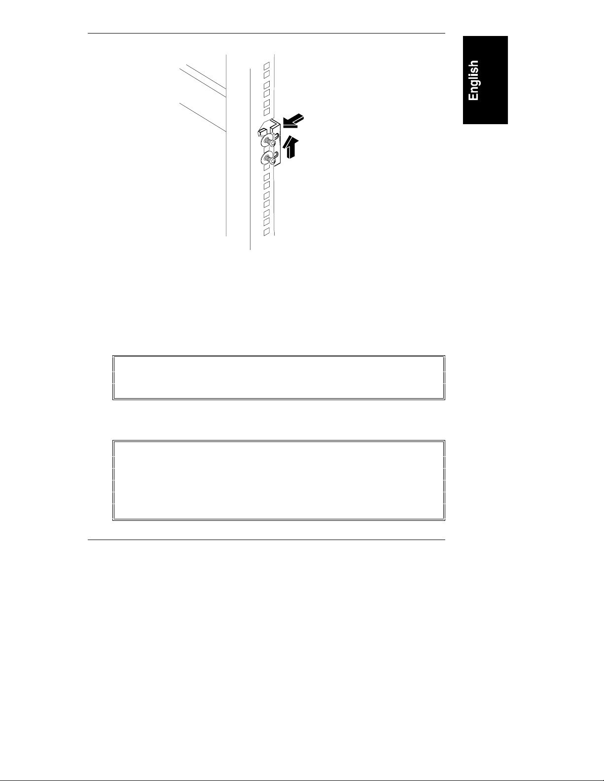
2. Place the mounting flange of the slide between the inside of the column
and the bar nut (see Figure 3-4). Do this at the front and rear of the slide.
3. Press the slide firmly against the columns, lift up against the screws, and
tighten all four screws.
NOTE It is very important to lift up on the slides prior to tightening
the screws. Tightening the screws without lifting up on the
slides will result in interference between the NetServer and
other equipment in the rack; you may not be able to slide the
NetServer into the rack enclosure after completing the
installation.
4. Repeat for the other slide.
10
Page 15
Chapter 3 Installation
Push In and Up
Figure 3-4. Mounting a Slide to a Column
Installing the NetServer
1. Extend the slides until you hear a click, indicating they are fully extended
in the locked-out position. Note that the slides do not come apart (see
Figure 3-3).
WARNING To prevent the rack from tipping over, be sure that the
stabilizing, anti-tip feature is installed on this rack enclosure
(see Figure 1-2).
2. Before you lift the NetServer, remove the power supply modules and the
hot-swap hard disk drives to reduce the weight.
WARNING This NetServer weighs up to 160 pounds (73 kg.) when fully
configured. Remove all power supply modules and hot-swap
hard disk drives before lifting the NetServer.
Use two people when moving the NetServer or lifting it into
the rack.
11
Page 16
Chapter 3 Installation
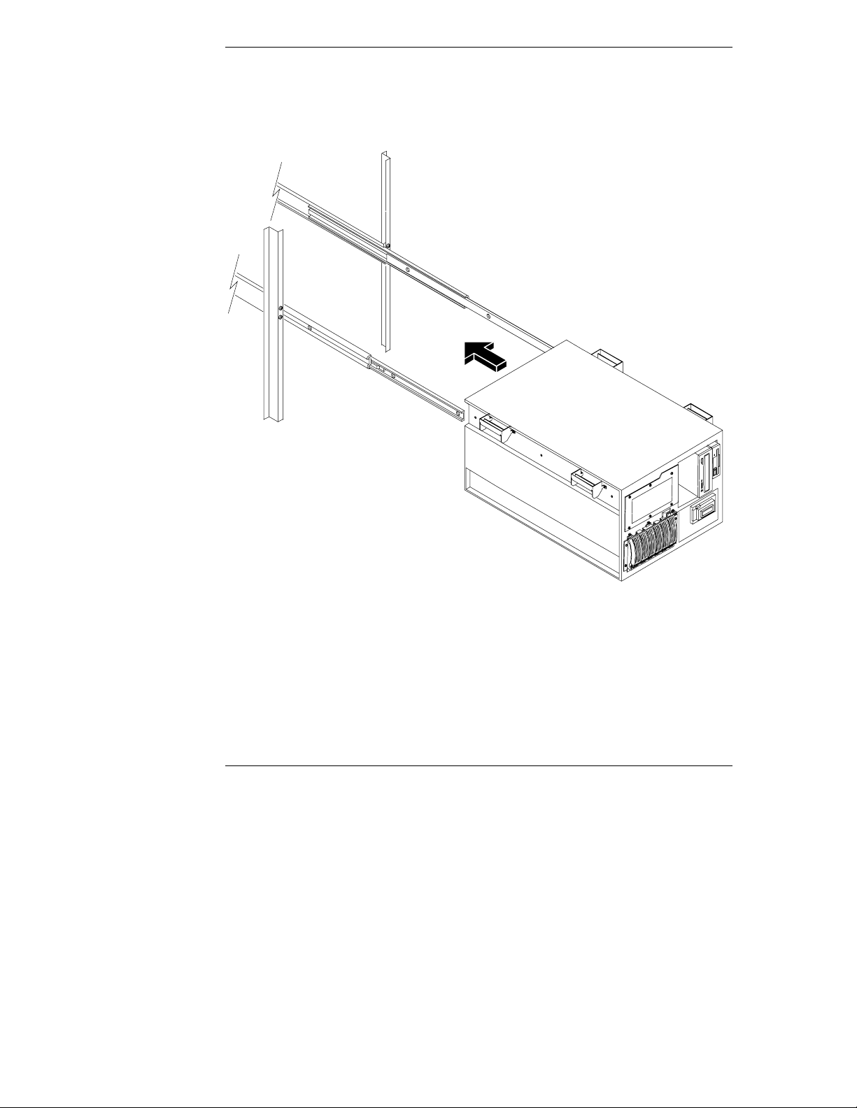
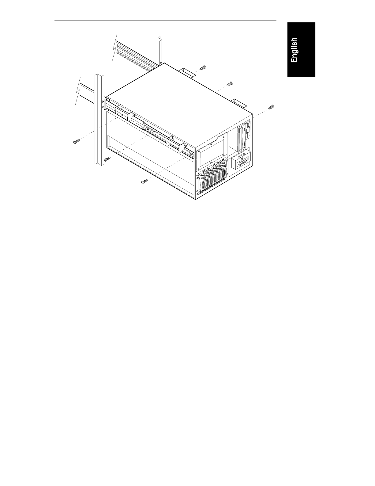
3. Using two people, lift the NetServer using the handles on each side. Move
the NetServer in between the extended slide members and position it so
that the handles are resting on the slide members (see Figure 3-5 and
Figure 3-6).
Figure 3-5. Lifting the Server Onto the Slide Members
4. Line up the mounting holes in the slide members with the holes in the
NetServer chassis, insert the three screws on each side, and tighten them
(see Figure 3-6).
12
Page 17
Chapter 3 Installation
Figure 3-6. Attaching the Slides to the Server Chassis
13
Page 18
Chapter 3 Installation
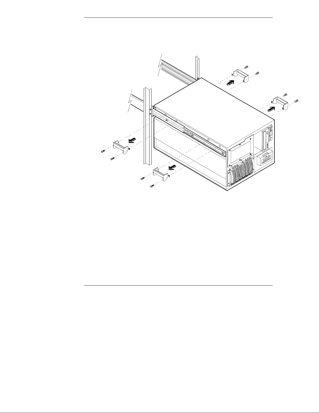
5. Remove the two screws from each of the four handles and remove them
(see Figure 3-7). Keep these handles and screws for later use, in case you
need to remove the NetServer and ship it.
Figure 3-7. Remove Mounting Handles
6. Reinstall power supply modules and hard disk modules removed earlier.
Installing the Recessed Mounting Brackets
The NetServer is held in place (inside the rack enclosure) by two recessed
brackets. These are attached to the face of the NetServer chassis and the two front
rack columns.
14
Page 19

Chapter 3 Installation
To install these brackets:
1. On both slide members, simultaneously depress the lockout releases and
push the NetServer completely into the rack enclosure (see Figure 3-8).
Lockout Release
Figure 3-8. Location of Lockout Releases
15
Page 20
Chapter 3 Installation
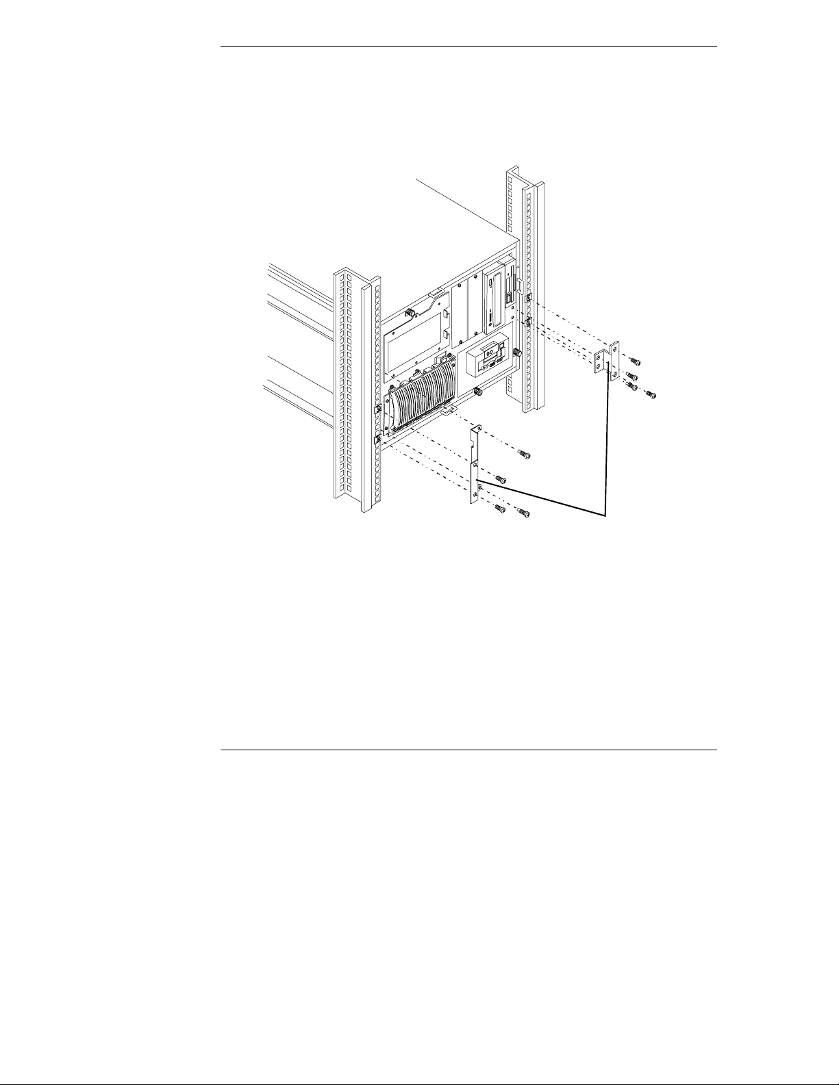
2. Install the two screws that hold the tall, left-hand bracket to the face of the
NetServer chassis (see Figure 3-9).
3. Install the two screws that hold the short, right-hand bracket to the face of
the NetServer chassis (see Figure 3-9).
Recessed Brackets
Figure 3-9. Installing the Recessed Mounting Brackets
4. Install two screws into the two holes in the left-hand recessed bracket and
into the two rack nuts (previously installed) on the left column (see
Figure 3-9), and tighten.
5. Install two screws into the two holes in the right-hand recessed bracket
and into the two rack nuts (previously installed) on the right column (see
Figure 3-9), and tighten.
16
Page 21
4 Warranty and Suppor t
Refer to the warranty statement provided with your original HP NetServer system
documentation for the warranty limitations, customer responsibilities, and other
terms and conditions.
CAUTION Improper installation of HP rack-mount components into
third-party racks may result in unreliable operation or
damage to the HP components. Repairs to HP components
due to improper installation into third-party racks are not
covered under the HP warranty.
Hewlett-Packard is not responsible for damage resulting from
the improper installation or operation of HP rack-mount
components into third-party racks, or unsafe environmental
conditions that exceed operational or non-operational
specifications of HP equipment.
HP rack enclosures, rack accessories, and installation
procedures are designed and tested to ensure that the
NetServer has adequate cooling airflow and proper
temperature control to maintain system reliability.
17
Page 22

Chapter 4 Warranty and Support
HP Repair and Telephone Support
Refer to the Service and Support chapter of your HP NetServer system
documentation for instructions on how to obtain HP repair and telephone
support.
18
Page 23

Index
C
Compaq, 1
F
fastening server to rack front, 14
fastening server to slides, 12
H
handles
removing after mounting, 14
L
lifting server into rack, 12
lockout releases, 15
R
recessed brackets, attaching, 16
S
slide location, 7
V
version of NetServer, 1
19
 Loading...