

Page 1

HP NetServer LC 2000/2000r
Installation Guide
HP Part Number D8514-90000
Printed November 1999
Page 2

Notice
The information contained in this document is subject to change without notice.
Hewlett-Packard makes no warranty of any kind with regard to this material,
including, but not limited to, the implied warranties of merchantability and fitness for
a particular purpose. Hewlett-Packard shall not be liable for errors contained herein or for
incidental or consequential damages in connection with the furnishing, performance, or use
of this material.
Hewlett-Packard assumes no responsibility for the use or reliability of its software on
equipment that is not furnished by Hewlett-Packard.
This document contains proprietary information that is protected by copyright. All rights
are reserved. No part of this document may be photocopied, reproduced, or translated to
another language without the prior written consent of Hewlett-Packard Company.
Windows NT
the U.S. and other countries. Novell and NetWare are registered trademarks of Novell,
Incorporated. OS/2 is a registered trademark of the International Business Machines
Corporation. SCO and SCO UNIX are registered trademarks of The Santa Cruz
Operation. UNIX is a registered trademark in the United States and other countries,
licensed exclusively through X/Open Company Limited. pcANYWHERE32 is a
trademark of Symantec Corporation. Red Hat is a registered trademark of Red Hat
Incorporated. Linux is a registered trademark of Linus Torvald.
Pentium™ is a U.S. trademark of Intel Corporation.
Symbios is a registered trademark of LSI Logic Corp. 3M is a trademark of the Minnesota
Mining and Manufacturing Company. Torx is a registered trademark of CamCar/Textron, Inc.
Tinnerman is a registered trademark of Eaton/Tinnerman.
Hewlett-Packard Company
Network Server Division
Technical Communications/MS 45SLE
10955 Tantau Avenue
Cupertino, California 95014 USA
© Copyright 1999, Hewlett-Packard Company.
, Windows 95, and Windows 98 are registered trademarks of Microsoft in
Audience Assumptions
The guide is for the person who installs, administers, and troubleshoots LAN servers.
Hewlett-Packard Company assumes you are qualified in the servicing of computer
equipment and trained in recognizing hazards in products with hazardous energy levels and
are familiar with weight and stability precautions for rack installations.
ii
Page 3

Contents
1 Setting Up the HP NetServer....................................................................... 1
Installation Guid eline s....................................................................................1
Pedestal Instal lation ...................................................................................... 2
Rack Mount Installation ................................................................................. 5
2 Controls, Ports, and Indicators................................................................... 9
Front of HP NetServer................................................................................... 9
Power, Reset, and Keyboard Lock B uttons.............................................. 10
Front Panel LED Indicators...................................................................... 11
Non-Hot Swap Devic e Indicators ............................................................. 13
Rear Panel Indicators and Ports .................................................................. 14
Power Supply Module Indicator ............................................................... 15
Communication Ports.............................................................................. 16
NIC Indicators.......................................................................................... 17
Applying Power to the HP NetServer........................................................... 18
Powering Up the HP NetServer............................................................... 18
Powering Down the HP NetServer........................................................... 18
Connecting AC Power to Multiple-Server Confi gur ations.......................... 18
Sleep States (ACPI ) ................................................................................ 19
3 Opening and Closing the HP NetServer ................................................... 21
Introduction ................................................................................................. 21
Tools Required........................................................................................ 21
Removing the HP NetServer’s Covers ......................................................... 22
Removing Covers – Rack-Mount (LC 2000r)............................................ 22
Removing Covers – Pedestal ( LC 2000) .................................................. 28
Removing the Pedestal............................................................................ 32
4 Installing Mass Storage Devices............................................................... 33
Introduction ................................................................................................. 33
Installing Stor age Dev ices After Shipment ............................................... 33
Tools Required........................................................................................ 33
Drive Bay Shelves................................................................................... 34
Boot Priority.............................................................................................34
Hardware Mirrori ng.................................................................................. 35
Mass Storage Guideli nes......................................................................... 36
iii
Page 4

Contents
Hot Swap Configuration Options.............................................................. 38
Cabling Configurations............................................................................ 43
Installing Hot Swap Hard Drives................................................................... 46
Removing Hot Swap Hard Drives................................................................. 50
Installing Non- Hot Swap Storage Devices.................................................... 51
Connecting External SCSI Devices.............................................................. 53
5 Installing Additional Memory.................................................................... 55
Introduction ................................................................................................. 55
Tools Required........................................................................................ 55
Memory Installation Guidelines ................................................................ 56
DIMM Ins ta l la t io n......................................................................................... 56
DIMM Removal............................................................................................ 59
6 Installing Additional Boards ..................................................................... 61
Introduction ................................................................................................. 61
Tested PCI Boards.................................................................................. 61
Tools Required........................................................................................ 61
Remote Control Card............................................................................... 61
Boot Priority.............................................................................................62
IRQ Settin g s............................................................................................ 63
System Board PCI Slots.......................................................................... 63
Installing Accessory Boards......................................................................... 65
7 Installing Additional Processors............................................................... 71
Introduction ................................................................................................. 71
Tools Required........................................................................................ 71
Processor Configur ation Guidelines......................................................... 71
Installing the Processor................................................................................ 73
8 Rack Mounting the HP NetServer ............................................................. 79
Introduction ................................................................................................. 79
Tools Required........................................................................................ 80
Safety Pre c a u tion s.................................................................................. 81
Preparing the Rac k...................................................................................... 82
HP NetServer Rack Mount Parts List....................................................... 82
Marking the Rack and Att ac hing Rac k Nuts ............................................. 82
Attaching the Colum n A dapters and Slides .............................................. 85
Placing the HP NetServer in the Rack......................................................87
Attaching the Cable M anagem ent Arm..................................................... 91
iv
Page 5

Contents
Attach ing the Fro n t B e ze l........................................................................ 94
Continuing with the Rack Installation Proc ess .............................................. 95
9 Connecting the Monitor, Keyboard, Mouse, and UPS ............................. 97
Introduction ................................................................................................. 97
Connecting the M onitor, Keyboard, and Mouse........................................ 97
Connecting the UPS (Uninterruptible Power Supply )................................ 98
10Configuring the HP NetServer................................................................... 99
Introduction ................................................................................................. 99
HP NetServer Navigator CD-ROM............................................................... 99
Contents of the Navigator CD-ROM – HP NetServer................................ 99
Obtaining HP Navigator CD-ROM Release History.................................100
Obtaining Up-to-Date Configuration Details.............................................101
Running Configur ation Assistant and Installation Assistant..........................103
Express Configuration ............................................................................103
Custom Configuration.............................................................................106
Replicate Configuration..........................................................................107
NOS Ins ta lla tio n.........................................................................................107
HP Management Solutions .........................................................................108
TopTools for Ser ver s..............................................................................108
TopTools Remote Control.......................................................................109
HP Integrated Remote Assistant.............................................................110
PcANYWHERE32...................................................................................111
NetServer Utilities...................................................................................111
Setup Utility................................................................................................112
Starting the Setup Utility.........................................................................112
Menu Bar ...............................................................................................112
Using the Setup Scr eens........................................................................113
Changing the System Date and Time......................................................114
Setting the HP NetServer's Boot Passwords...........................................115
Changing Internal Dev ice Boot Priority....................................................118
Clearing CMOS......................................................................................120
SCSI Configuration Utility...........................................................................121
Running the Navi gator CD-ROM on a Windows PC....................................122
Contents of the Navigator CD-ROM – Windows PC................................122
Up-to-Date Configuration Details............................................................124
11Information Assistant...............................................................................127
v
Page 6

Contents
Overview....................................................................................................127
Using Information Assistant........................................................................127
Getting Help...........................................................................................127
Finding Information.................................................................................127
Copying and Printing Information............................................................129
Installing HP Information Assistant Software...............................................129
Install ing fr om the CD-R OM....................................................................129
12Trouble shooti ng.......................................................................................131
Troubleshooti ng Tools................................................................................131
Common In stallation Prob lems...................................................................132
If the System Will Not Power On.............................................................132
Troubleshooti ng S equenc e.....................................................................133
Error Message Is Displayed....................................................................134
No Error Messages Displayed................................................................135
Clearing the System Configuration..........................................................137
Hardware Problems....................................................................................139
Display Does Not Work ...........................................................................139
Keyboard or Mouse Do Not Work ...........................................................140
CD-ROM Drive Does Not Work...............................................................140
Hard Disk Drives Do Not Work................................................................141
Password Problems....................................................................................141
Battery Pr o b lems........................................................................................142
13Alternative Rack M ounting.......................................................................145
Introduction ................................................................................................145
Tools Required.......................................................................................146
Safety Pre c a u tion s.................................................................................147
Preparing the Rac k.....................................................................................148
HP NetServer Rack Mount Parts List......................................................148
Mounting Column Adapters ....................................................................148
Attaching the Slides to the Rack.............................................................150
Placing the HP NetServer in the Rack.........................................................153
Attaching the Cable M anagem ent Arm....................................................157
Attach ing the Fro n t B e ze l.......................................................................159
Continuing with the Rack Installation Proc ess .............................................160
A Specifications...........................................................................................161
Power Requirement s ..................................................................................161
vi
Page 7

Contents
Environment al Requirements......................................................................163
Physical Requirem ents...............................................................................164
Video Support ........................................................................................165
B Regulatory Information ............................................................................167
Regulatory Noti c es - Elec trom agnetic Compliance......................................167
Notice for United States..........................................................................167
Notice for Canada (I ndustr y Canada)......................................................168
Notice for Japan .....................................................................................169
Notice for Kore a.....................................................................................170
Notice for Ta iwan....................................................................................1 7 1
Notice for European Union......................................................................171
Declaration of Conformity (US, EU, Australia).........................................172
Regulatory Noti c es - Pr oduc t Safety ...........................................................173
CD-ROM and Laser Safety St atements...................................................173
Battery Sta temen ts.................................................................................175
Noise and Ergonomic S afety Statements................................................176
C Service and Suppo rt.................................................................................177
D Warranty and Sof tware Li cense...............................................................179
Warranty....................................................................................................179
HP Software Product Lic ense Agreement ...................................................179
Index..............................................................................................................181
vii
Page 8

Page 9
1 Setting Up the HP NetSe rver
LC 2000r
(Rack-mounted Model)
Installation Guidelines
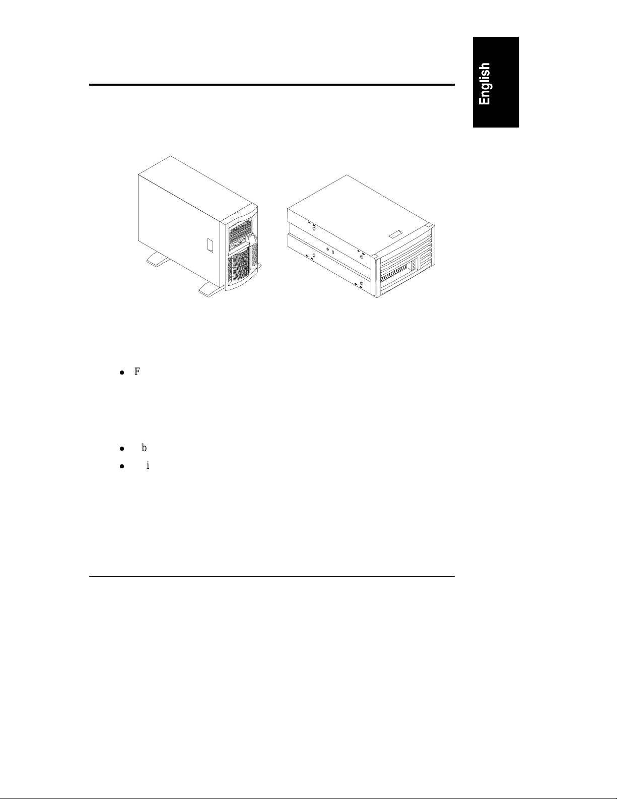
This Installation Guide is for the HP NetServer LC 2000 pedestal model, and the
HP NetServer LC 2000r rack-optimize d mo de l.
LC 2000
(Pedestal Model)
Figure 1-1. HP Net Servers
l
For a trouble-free installation, read this chapter before taking the HP
NetServer out of its box. This chapter lists what to do, and in what order.
Ch oos e e ither:
◊ HP NetServer LC 2000 for pedestal installation
◊ HP NetServer LC 2000r for rack-mounted installation
l
Obser ve a ll warnings and caut ions.
l
Unique to the LC 2000r are the:
◊ Universal bezel that fits HP System/E and System/U racks, as well as
some third-party racks
◊ Unique Bezel hinge and latch
◊ Rack slides
◊ Cable Management Arm
1
Page 10
Chapter 1 Setting Up the HP NetServer
l
Use the removable and reusable rack-mounting handles to move and place
the LC 2 000r in the rack . Remove th e handles on ly when you ha ve secu red
the HP NetServer to the rack slides.
l
The height at which you install the HP NetServer in the rack determines
how you will service the HP NetServer.
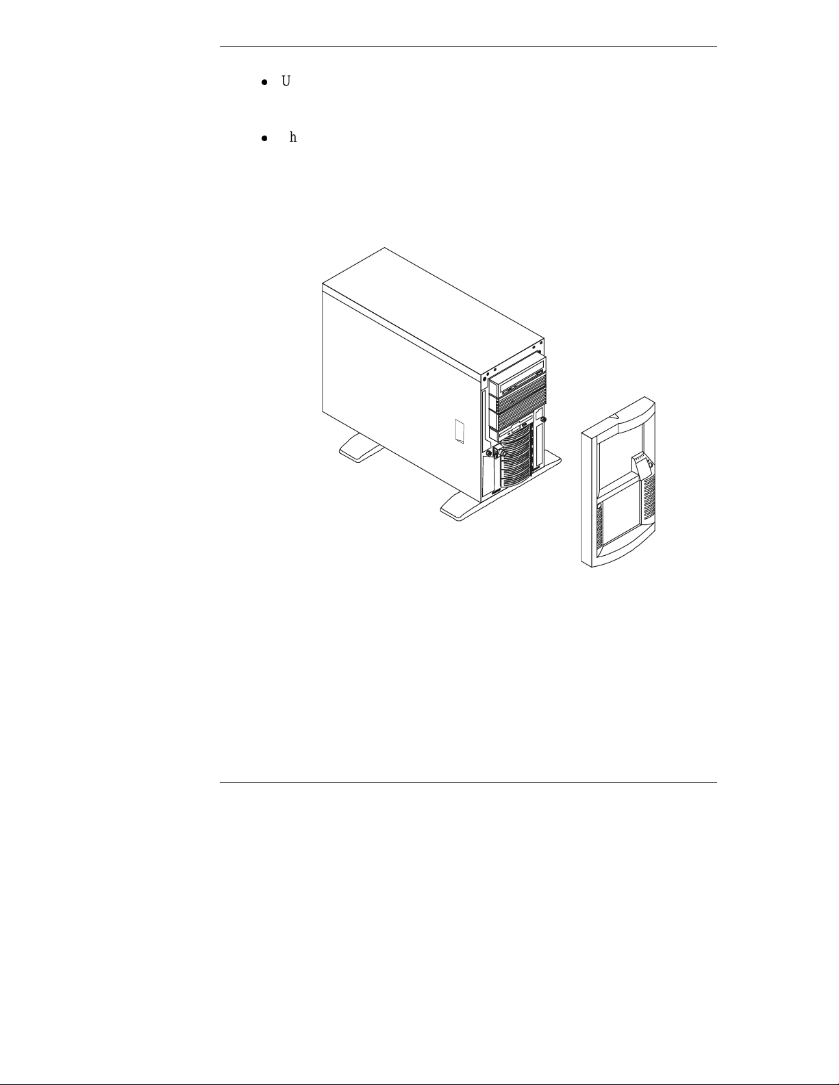
Pedestal Installation
Follow the setu p steps in the ex act order shown below for a successfu l pedest al
install ation. Ski p any ste p s that do no t ap ply to your installation.
Figure 1-2. HP NetServer LC 2000
1. Unpack the shipping box and ver ify the contents ag a inst the Con tents List
included with your HP NetServer.
a. If anything is missing or damaged, call your reseller.
b. Store the empty boxes a nd pack in g material in a safe place.
This is especially important if you plan to ship the HP NetServer
elsewhere for final installation.
2
Page 11

Chapter 1 Setting Up the HP NetServer
CAUTION The HP NetServer LC 2000 weighs approximately 80 lbs. (36
kg), which may be more than one person should lift. Do not
attempt to lift the HP NetServer by yourself. Failure to
observe this warning could result in serious injury, or damage
to the HP NetServer.
2. Familiariz e yourself wit h the HP NetS erver’s controls, ports, an d
indi cators.
Refer t o Chapt e r 2, "C ontrols, P orts, and Indic ator s ."
3. If you have option al items to a d d t o the HP NetServer (memory, accessory
boards, or processors ), remove the front be zel and th e le ft cover.
◊ If there are no optional items to install, skip to step 8.
◊ Refer to Ch apter 3, "O pening and Closi ng the HP NetServer."
4. If you have item s su ch as a processor, DIMMs, and access ory boards to
install, do so at this time.
All these items are installed on the system board without removing it and
can be installed at the same time.
Refer to Chapter 5, "Installing Additional Memory," Chapter 6, "Installing
Additional Board s ," an d Chap ter 7, "Installing A dditiona l Processor s."
5. Install internal non-hot-swap mass storage devices such as hard drives and
tape back-ups into the front of the HP NetServer.
Refer to Chapter 4, "Installing Mass Storage Devices."
6. Reconnect all in ternal cables.
7. Replace all covers, including the bezel.
Refer t o Chapt e r 3, "Openi ng and Closi ng the HP NetServer."
8. Install all Hot Swap disk drives into the front of the NetServer.
Refer to Chapter 4, "Installing Mass Storage Devices."
9. If a second power supply (optional) is needed, install it into the rear of the
HP NetSe rv e r.
Refer to the Power Supply accessory guide.
10. Hook up the monitor, keyboard, and mouse to the rear of the HP
NetServer.
Refer t o Chapt e r 9, "C onnec tin g M onit or, K eyboard, M ouse, and UPS. "
3
Page 12

Chapter 1 Setting Up the HP NetServer
11. Connect all ot her external cables to the rear of the HP NetSer ver.
12. Obtain the re le ase history of the HP NetServ er Nav igat or CD-RO M
provided with the HP NetServer to ensure you have the latest Navigator
CD-ROM.
Refer to Chapter 10, "Configuring the HP NetServer."
13. Power up the HP NetServer.
Refer t o Chapt e r 2, "C ontrols, P orts, and Indic ator s ."
14. In sert the Navigator CD-ROM and reboot the HP NetServer.
15. Check the Navigator README file for imp ort ant insta l la tion information.
Refer to Chapter 10, "Configuring the HP NetServer."
16. Configure th e HP NetServer with Con fig urati on Assi st ant fr om the
Navigator CD-ROM, using the Express Configuration option.
Refer to Chapter 10, "Configuring the HP NetServer."
NOTE To fully configure the HP NetServer, all external components
should be cabled an d online.
17. Ve ri fy the HP N e tServer ’s operat ion and troubles hoot if n ec e s s ar y.
Your HP NetServer installation should be complete. If not, refer to
Chapter 12, "Troubleshooting."
18. If you plan to ship the fully-configured HP NetServer LC 2000 to a
different destination:
a. Label each cable and component to facilitate re-assembly.
b. Repack the components in the origin al packing mat erial, and prepar e
each on e for shipment.
CAUTION It is critical to disassemble and rebox all electronic
components before reshipment. Electronic components
(especially hard disk drives) can sustain damage when shipped
in rack enclosures.
4
Page 13
Chapter 1 Setting Up the HP NetServer
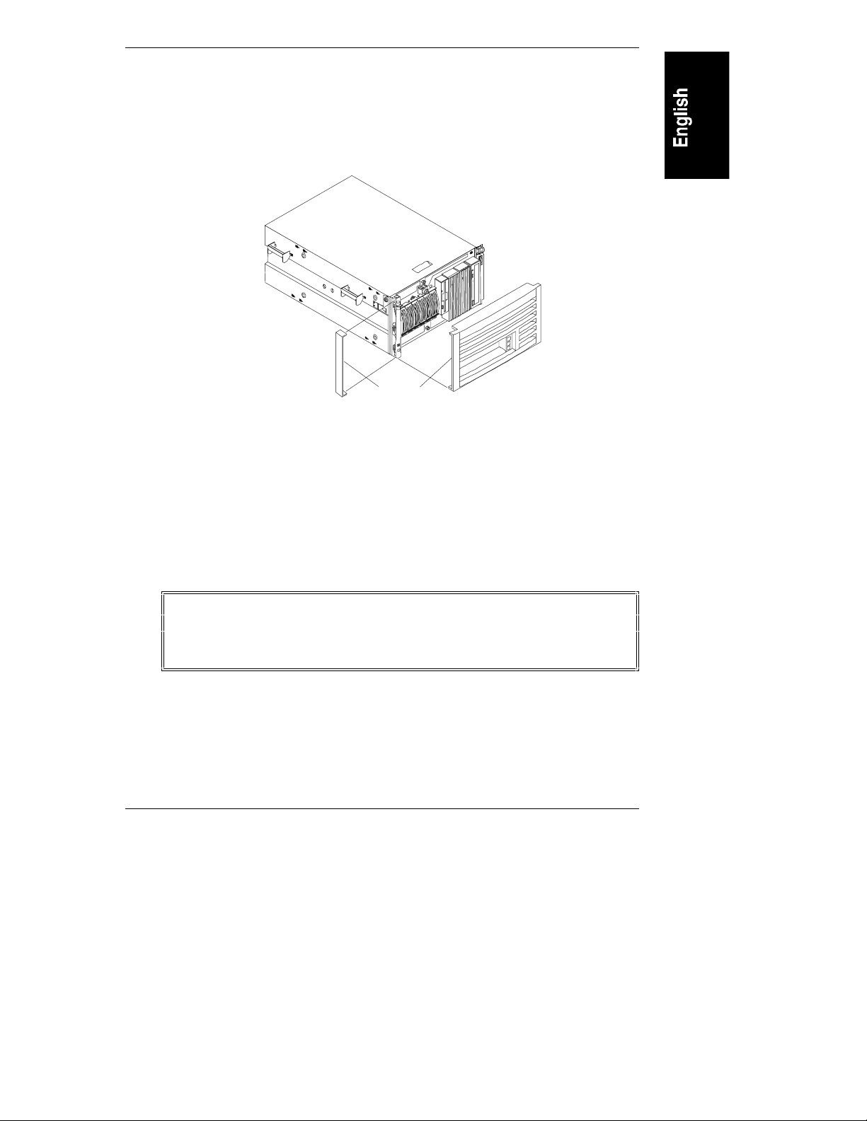
Rack Mount Installation
Follow the setu p steps in the ex act order shown below for a successfu l rack
install ation. Ski p any ste p s that do no t ap ply to your installation.
Shown
Figure 1-3. HP NetServer LC 2000r
Removed for Detail
1. Unpa ck the shipping box and verify the contents ag ainst the Content s Li st
included with your HP NetServer.
a. If anything is missing or damaged, call your reseller.
b. Store the empty boxes a nd pack in g material in a safe place.
This is especially important if you plan to ship the HP NetServer
elsewhere for final installation.
WARNING To preven t serious injury or damage to the HP NetServer, do
not attempt to lift the HP NetServer by yourself. The HP
NetServer LC 2000r weighs approximately 80 lbs. (36 kg) and
requires more t han one person to lift it.
2. Familiariz e yourself wit h the HP NetServer’s controls , ports, and
indi cators.
Refer t o Chapt e r 2, "C ontrols, P orts, and Indic ator s ."
5
Page 14

Chapter 1 Setting Up the HP NetServer
3. If you ha ve optional items to a d d to the HP NetSer ver (memory, access ory
boar d s, mass storag e, or process ors), remove the bezel and the top cover.
◊ If there are no optional items to install, skip to Step 12.
◊ Refer to Ch apter 3, "O pening and Closi ng the HP NetServer."
4. If you have item s su ch as a processor, DIMMs, and access ory boards to
install, do so at this time.
All these items are installed on the system board without removing it and
can be installed at the same time.
Refer to Chapter 5, "Installing Additional Memory," Chapter 6, "Installing
Additional Board s ," an d Chap ter 7, "Installing A dditiona l Processor s."
5. If you ar e adding internal mass storag e devices such as hard dr ives or tap e
back up d evi ces into th e front of th e HP NetServer, do so nex t.
Refer to Chapter 4, "Installing Mass Storage Devices."
6. Reconnect int ernal cables as need ed .
7. In stall the HP NetServer LC 2000r into the rack.
Refer t o Chapt e r 8, "Rack-Moun tin g the HP NetServer ," for th e Ra c k
System/E or System/U, or Chapter 13, "Alternative Rack Mounting," for
the HP Systems Rack.
8. If th e rack-mount system accep ts the C a ble Management Arm, install it
onto the rear of the r ack and th e HP NetServer.
Refer t o Chapt e r 8, "Rack-Moun tin g the HP NetServer ," for a Rack
System/E or System/U, or Chapter 13, "Alternative Rack Mounting," for
the HP Systems Rack.
9. If a cover was removed earlier, replace the cover, but not the bezel.
Refer t o Chapt e r 3, "Openi ng and Closi ng the HP NetServer."
10. Install the SCSI Hot-Swap hard drives into the front of the HP NetServer.
The bezel must be removed to install the SCSI Hot-Swap drives. Refer to
Chapter 4, "Installing Mass Storage Devices."
11. Replace the bezel.
Refer t o Chapt e r 3, "Openi ng and Closi ng the HP NetServer."
12. If a second power supply (optional) is required, install it into the rear of the
HP NetSe rv e r.
Refer to the Power Supply accessory guide.
6
Page 15

Chapter 1 Setting Up the HP NetServer
13. Connect th e monitor, keyboard, an d mou se to the rear of t he HP NetServer.
Refer t o Chapt e r 9, "C onnec tin g M onit or, K eyboard, M ouse, and UPS. "
14. Connect all ot her external cables to the rear of the HP NetSer ver.
15. Obtain the re le ase history of the HP NetServ er Nav igat or CD-RO M
provided with the HP NetServer, to ensure you have the latest Navigator
CD-ROM.
Refer to Chapter 10, "Configuring the HP NetServer."
16. Power up the HP NetServer.
Refer t o Chapt e r 2, "C ontrols, P orts, and Indic ator s ."
17. In sert the Navigator CD-ROM and reboot the HP NetServer.
18. Check the Navigator README file for imp ort ant insta l la tion information.
Refer to Chapter 10, "Configuring the HP NetServer."
19. Configure th e HP NetServer with Con fig urati on Assi st ant fr om the
Navigator CD-ROM, using the Express Configuration option.
Refer to Chapter 10, "Configuring the HP NetServer."
NOTE To fully configure the HP NetServer, all the rack components
should be cabled and online (though not necessarily installed in
the ra ck.) Use the HP NetServer LC 2000r Rack Cabling
Reference Guide for more details.
20. Ve ri fy the HP N e tServer ’s operat ion and troubles hoot as ne ce s sary.
Your HP NetServer installation should be complete. If not, refer to
Chapter 12, "Troubleshooting."
21. If you plan to ship the fully-configured HP NetServer LC 2000r to a
different destination:
a. Label each cable and component to facilitate re-assembly.
b. Remove all compon en ts from th e ra ck, incl uding external mass st or age.
c. Repack the compon en ts in the ori ginal pack in g material , an d prepar e
each on e for shipment.
CAUTION It is critical to disassemble and rebox all electronic
components before reshipment. Electronic components
(especially hard disk drives) can sustain damage when shipped
in rack enclosures.
7
Page 16

Page 17
2 Controls, Ports, and Indicators
Keyboard
Lock LED
Power LED
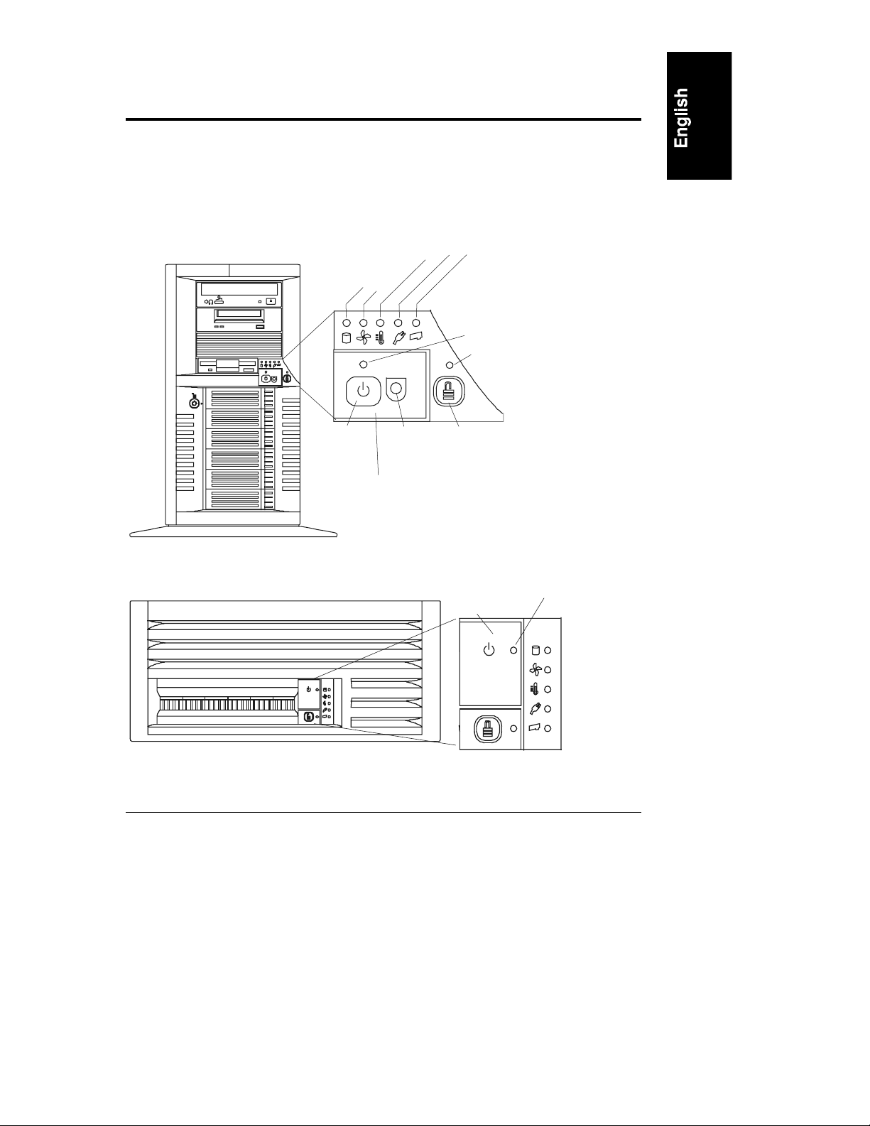
Front of HP NetServer
This chapter describes the contr ols, ports and indica tors on the fr ont and rear of
the HP NetServer LC 2000 and LC 2000r. Figures 2-1 and 2-2 below show the
HP NetServers LC 2000/LC 2000r as pedestal and rack models respectively.
e
r
u
d
at
e
Supply
r
v
r
e
e
er
p
Disk
Fa
n
e
T
s
m
ow
P
Re
RESET
Power
Button
RESET
Reset
Button
Keyboard Lock
Button
Cover Removed
for Clarity
Figure 2-1. HP NetServer LC 2000 (front view)
Cover
Closed
Figure 2-2. HP NetServer LC 2000r (front view)
Power
LED
9
Page 18

Chapter 2 Control s, Por t s, an d In di cators
Power, Res et, and Ke yb oard Lock Bu tton s
The control buttons shown in Figures 2-1 and 2-2 are described in the Table 2-1.
Table 2-1. Power, Reset, and Keyboard Lock Buttons and LEDs
Control/LED Description
Power On/Off/
Sleep Button
Power On/Off/
Sleep LED
Reset Button
RESET
Keyboard
Lock Button
Keyboard
Lock LED
This button turns the HP NetServer power On or Off, and if
available, also transitions the NetServer between Power On
and sleep s tates. If sl eep states are not ava ilable, th en this
button only turns power On or Off.
The sleep states are NOS dependent and not available if your
NOS does not support power management based on the ACPI
(Advanced Configuration and Power Interface) standard.
Refer to "Applying Power to the HP NetServer" and "Sleep
States (ACPI)" later in this chapter.
This LED glows stea dy green when power i s on, and goes
dark when the NetServer is powered off.
If the NetServer is under ACPI control, this LED will flash
green on and off when in an inactive sleep state.
Performs a system (hard) reset.
Puts the NetServer in a locked mode, which locks the
keyboard, if th e NetServer wa s configured for ke yboard lock
or Network Server mode in the Setup Utility.
This includes keyboard lock, power button lock, and video
blanking. The reset button is also disabled.
This LED gl ows solid green when the HP NetServer ’s
keyboard is locked, and is dark at all other times.
10
Page 19

Chapter 2 Controls, Port s and Ind ic ator s
Front Pan el LED I n dicator s
Table 2-2. Component Indicators
LED ICON Description
Disk LED
Temperature
LED
Fan LED
RPS LED
This Disk LED has two distinctive states:
l
off for inactive operation
l
blinking Green for SCSI drive activity.
This Temperature LED has three di s tincti ve colors:
l
steady Green for normal operation
l
blinkin g Red at 1 Hz bli nk rate for an
overheated con dition inside the HP NetServer
l
blinking Amber at 0.5 Hz blink rate for a
warning condition.
This Fan LED ha s three dis tincti ve col ors:
l
steady Green for normal operation
l
blinkin g Red at 1 Hz bli nk rate for a nonoperational fan condition inside the NetServer
l
blinking Amber at 0.5 Hz blink rate for a
warning condition indicating one of the fans
may be turning too slowly.
This RPS (Redundant Power Supply) LED has three
dist inctive col ors:
l
steady Green for normal operation
l
blinkin g Red at 1 Hz bli nk rate for a bad p ow e r
supply
l
blinking Amber at 0.5 Hz blink rate for a
warning condition indic ating a power supp ly
may not be working correctly.
Reserved
T his LED is re s erved and not used i n th is re lease.
11
Page 20

Chapter 2 Control s, Por t s, an d In di cators
Hot Swap
Hard Disk Drives
Drive (Optional)
Hot Swap Disk Drive Indicators
Each of the Hot Swap hard disk drives has two LED indicators, one for
operational status and one for activity status. Light pipes on each drive module
tran sm it light to the front from the LED s on th e inside rear of t he hot-swap mass
storage cage. See Table 2-3 and Figure 2-3.
Table 2-3. Hot Swap Hard Disk Drive LED Indications
Status LED Activity Status LED
Off: Disk not present, or not
Off: No disk activity
conn ected to th e cag e
Green (solid): Disk present Green (flashing): Accessing disk
Green (solid for more than one
minute): Disk spinning up, or "hung"
Amber (flashing): Disk failure
predicted
Red (flashing): Disk failed
Red (solid): N o +12 vol t powe r
DAT Tape
CD-ROM Drive
Activity
LED
Flexible Disk Drive
Activity
LED
Eject
Button
Eject
Button
RESET
Status
LEDs
Status
LED
Activity
LED
Figure 2-3. Drive LED Indicators
12
Page 21

Chapter 2 Controls, Port s and Ind ic ator s
Non-Hot Swap Dev ice In dicator s
The indicators for non-Hot Swap devices, which provide operational status, are
also shown in Figure 2-3. The indicators shown in Figure 2-3 also apply to the
rack-mount model (LC 2000r). See Table 2-4 for Backup Tape drive LED Codes.
Table 2-4. Backup Tape Drive LED Codes
Lef t LE D Right LED Definition
Off Off No Power
On Off Cartridge Loaded, but No activity
Flashing* Off Cartridge Loaded and Active
Pulsing** Off Loading/Unloading/Ejecting/Power-On
Off On Self Test Fa il
Off Pulsing** No Cartridge, but Caution (cleaning required)
On Pulsing** Cartridge Loaded, but Caution (cleaning required)
Flashing* Pulsing**
Pulsing** Pulsing** Cartridge Loading/Unloading, Caution (cleaning
Cartridge Loaded, Drive Active, Caution (cleaning
required)
required)
* Flashing at 4 Hz rate
** Pulsing at 2 Hz rate
NOTE For more information on the HP Tape Drive and its error
codes, refer to the documentation provided with the tape drive
or refer to Hewlett-Packard’s web site, at:
http://www.hp.com
.
Refer to Chapter 4, "Installing Mass Storage Devices," for
install ation inf ormatio n.
13
Page 22
Chapter 2 Control s, Por t s, an d In di cators
Communication
Knockout for
SCSI Connector
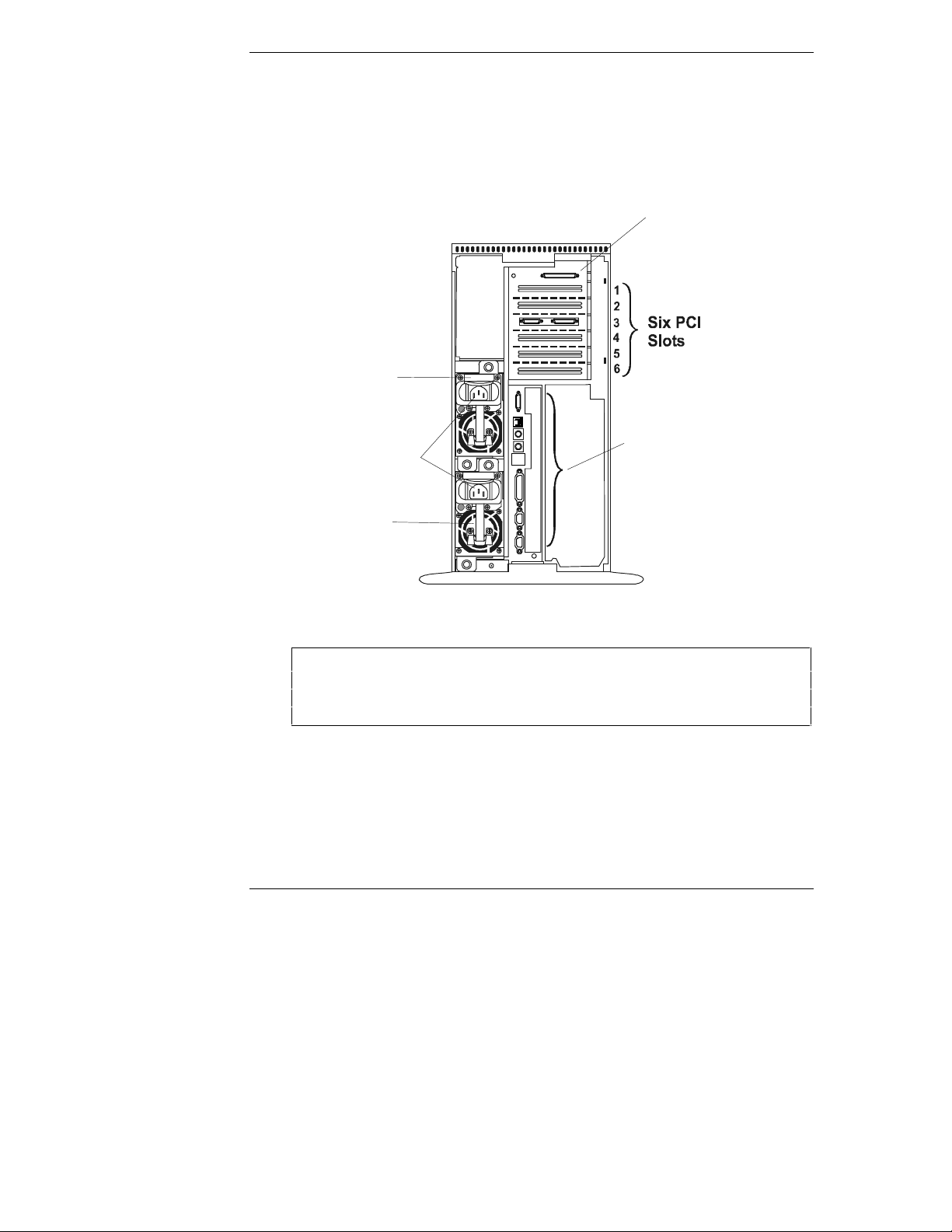
Rear Panel Indicators and Ports
The HP NetServer’s rear panel in cludes communication ports, the AC power
inlets, and the NetServer’s power supplies.
Fi g ure 2-4 shows t he rear of the HP NetServer.
External
(Optional)
Redundant
Power
Supply #2
(Optional)
Ports
AC Power
Inlets
14
Power
Supply #1
Figur e 2-4. Rear Panel of the HP NetServer
CAUTION To prevent a power supply from overheating, ensure the other
power supply opening remains covered, if a second supply is
not used. If the second supply is used, keep the cover in case
you need to remove one supply for repair.
Page 23
Chapter 2 Controls, Port s and Ind ic ator s
e
Strainrelief
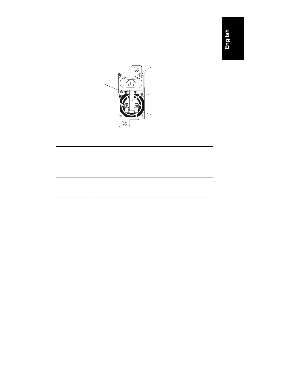
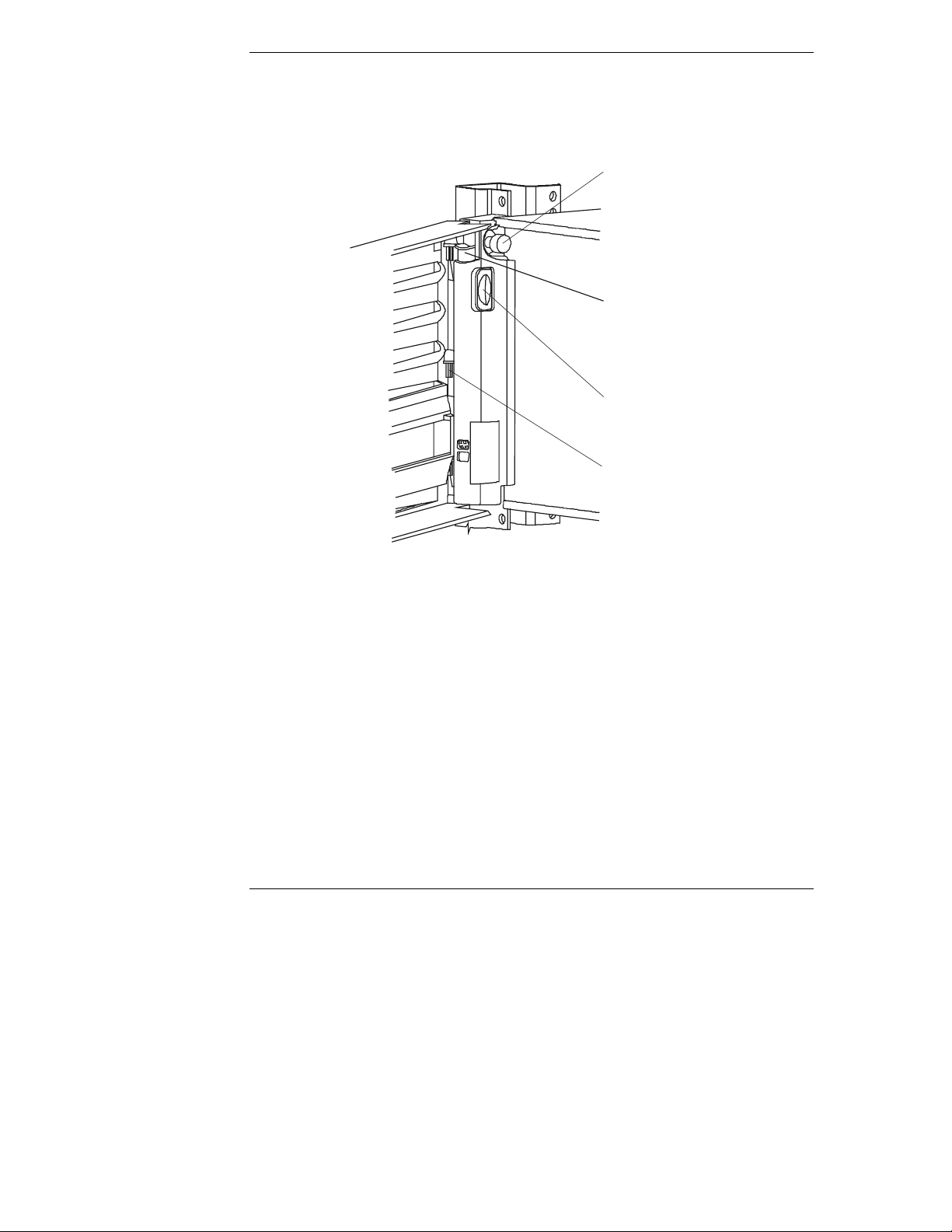
Power Suppl y M odule I n dicator
Each HP NetServer power supply module has an indicator as shown in Figure 2-5,
and each power supply has its own power cord connection. The HP NetServer
comes with one power supply module standard, and a second power supply
module for redundancy is optional.
Releas
Latch
Power
Indicator
Handle
Fi gur e 2-5. Power Supply LED
NOTE The release latch, which is spring loaded, must be up to insert
the power cord. The power supply can not be removed from the
chas sis with the p ower cord conn ected to the AC In connect or.
The power cord must be removed before pushing down on the
release latch to free the power supply from the chassis.
Table 2-5. Power Supply LED Indicator Descriptions
Green LED Power Supply and NetServer Status
St eady Green This indicates the HP NetServer is powered up and operating
normally, or is in an ACPI suspend state.
Off This indicates the NetServer is powered off, the AC line cord
is unplugged, or the power supply has failed, which may
include a fan failure (turning too slowly). If a fan fails in one
of two supplies, the defective supply will continue to operate
until it reaches the thermal shutdown limit. The second power
supply (redundant power supply) will continue to operate
providing the necessary power. Refer to Chapter 12,
"Troubleshooting."
15
Page 24
Chapter 2 Control s, Por t s, an d In di cators
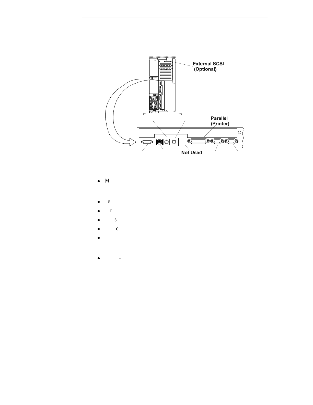
Serial
Communication Ports
The connectors on the HP NetSer ver’s rear panel are shown in Figure 2-6 and
described below.
Keyboard Mouse
16
Video NIC
Management
(Embedded)
Figure 2-6. Rear Panel Ports
l
Management – This connector supports the embedded Integrated Remote
Assistant and lin k s the HP NetServer to a console for r eal time monitoring
and diagnosis of the NetServer's operation.
l
Serial A – This is the standard serial port connector.
l
Parallel – This is the standard parallel printer port connection.
l
Mouse – Th is connector accept s a s tandard P S /2 mous e.
l
Keyboard – This connector accepts a s tandar d PS/2 ke yboard .
l
NIC – This connector supports the embedded NIC (Network Interface
Card) port on the system board. This is a RJ-45 connector supporting
10/100 BaseT Ethernet.
l
Vid e o – Thi s c onnec tor provide s th e video s igna l to dr ive the NetSer ve r's
monitor. Refer to "Video Support" in Appendix A for drivers and
supported resolutions.
Page 25
Chapter 2 Controls, Port s and Ind ic ator s
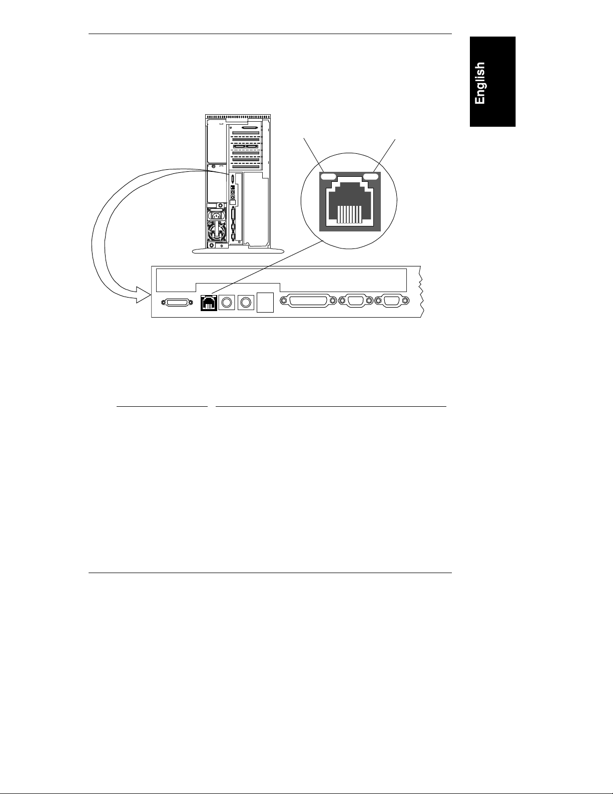
NIC Indicators
The embedded NIC (Network Interface Card) has two LEDs associated with it,
which can only be seen from the rear of the HP NetSer ver. See Figure 2-7 and
Table 2-6.
Link/Activity
LED
Figure 2-7. NIC LEDs
Table 2-6. NIC LED Code
Indicator Definition
Link/Activity LED
This LED turns solid green to indicate that it is
link ed and properly conn ected.
The gr een LED blinks to indicat e th e embedded
NIC (network adapter) is active and transferring
data to/from the NIC. The rate of blinking varies
directly with network traffic.
10/100 Mbps LED
This yellow LED turns on to indicate when the
NIC is supporting transfers of 100 Mbps (million
bits per second).
When it is off, the NI C is su pport ing tr ansfers of
10 Mbps.
Transfer Rate
LED
17
Page 26

Chapter 2 Control s, Por t s, an d In di cators
Applying Power to the HP NetServe r
Powering Up the HP NetServer
1. Ensure the HP NetServer’s power cord or p ower cords are connect ed to the
power source. See Figure 2-4.
2. Pr ess the Power button on the front control panel. See Figure 2-1 or 2-2.
NOTE Each time AC power is applied (power cord is plugged in),
ther e is a 15 s econd dela y (self test) bef ore the front control
panel will respond to your actions.
Powering Down the HP NetSer ver
1. Log off all users a nd , if necessary, back-up files.
2. Follow instructi ons in your network operating system (NOS)
documentation to gracefully shut down all networking software and
applications.
3. Press the power switch on th e HP NetServer’s control panel when
pr ompted by the operating system.
Normally, this completes the shutdown procedure.
NOTE The power supply will continue to provide standby voltage to
the HP NetServer until th e power cord(s) is/ar e di s connect ed.
Connecting AC Power to M ultiple-S erv er Configurat ions
The HP NetServer temporarily draws a large "inrush current," when first
conn ected to an AC power s ource. Th is also occurs when the NetServer is in a
standby mode (power is turned off and the power cord is plugged into AC power).
The inrush current is much greater than the NetServer’s normal operating current
and generally, the AC power source can handle the normal inrush current.
However, if you install several HP NetServers on one circuit, precaution s are
necessary. If there is a power failure and power is then restored, all the servers
immediately begin to draw inrush current at the same time. If the circuit breakers
on th e in com ing power l ine have ins u ffi cient ca pability, the brea ker may trip an d
thus prevent the servers from powering up.
When preparing your site for installation, allow for the additional inrush current.
See "Power Requirements" in Appendix A.
18
Page 27

Chapter 2 Controls, Port s and Ind ic ator s
Sleep States (A CPI )
The HP NetServer supports the ACPI (Advanced Configuration and Power
Interface) st andard , which is a key component of a NOS’s directed power
management. The supported features are only available when an ACPI-compliant
NOS is installed on the NetServer. The term “sleep state” refer s t o any of several
reduced power consump tion st at es in whi ch normal NOS activity has ceased.
The NetServer supports several sleep states, including a sleep state with a short
wake-up time, sometimes referred to as “standby” or “suspend” by various
operating systems. In this sleep state the NetServer appears to be off, and is
indicated by n o display on the monitor and no activity for the CD-ROM or
internal har d drives. Howev er, th e power LED is slowl y flashin g and the fan s ar e
operating.
An additional sleep state supported by the NetServer is on e with a slower wake-up
time, sometimes referred to as “hibernate” by var ious operating systems. In this
sleep state, the NetServer appears to be off as mentioned earlier, but the fans and
the power LED are also turned off. This sleep state's unique feature (and the
reason for its slower wake-up time) is that the NetServer's state (applications
running, screens open, etc.) just pri or to hiberna te has been saved to disk an d mus t
be restored from disk upon wa ke-up. This method of restoring the NetServer's
operation is much faster than rebooting the NetServer, which would require
running all the start -u p self-test s before starting the NOS.
The NetServer supports certain types of system activity, which is used as wake-up
events from these sleep states. These wake-up events can be generated from the
power button, LAN activity, and scheduled events. The embedded Integrated
Remote Assistan t also has the capability of waking up the NetServer.
NOTE The HP NetServer’s power management policies (transitions
between variou s p ower states) and th e user op tions are specific
to the particular ACPI -compliant NOS installed on the
NetServer. I f your resp ecti ve NOS is AC PI -comp li ant , r efer t o
the power management features in the instructions provided for
more information.
The HP NetServer’s power button can be configured to initiate a sleep state (Sleep
button) or a “soft off” or graceful shutdown of the NOS, rather than an immediate
shutdown of the power supply. The power button configurations are dependent on
the user interface pr ovided by th e ACPI- compl iant NOS. While power
management is under the control of the ACPI-compliant NOS, the HP NetServer’s
power button is capable of an overr ide in case of a non-responsive NOS.
19
Page 28

Chapter 2 Control s, Por t s, an d In di cators
NOTE The HP NetServer power button will force a power down
without waitin g for th e NOS to gracefull y shut down th e
system if the power button is pressed and held in excess of four
seconds.
CAUTION If the power button override is used, there is a strong
possibility of corrupted or lost data.
20
Page 29

3 Opening and Closing the HP
NetServer
Introduction
This chapter describes how to safely extend the rack-mounted HP NetServer
LC 2000r out of the rack and how to remove and replace the covers from the
HP NetServer LC 2000r and the pedestal model, HP NetServer LC 2000. This
chapter also describes how to remove and replace the pedestal base from the
HP NetServer LC 2000.
WARNING Before removing the covers, shut down the operating system
and di scon nect the power cor d s and unplug t elephon e ca bles.
Disconnect the power cords to avoid exposure to high energy
levels t h at may cause burns when p ar ts are short-cir cu ited by
metal objects, such as tools or jewelry. Disconnect telephone
cables to avoid exposure to a shock hazard from telephone
ringing voltages.
Tools Requ ir ed
l
An anti-static service kit (3M™ 8501/8502/8503 or equivalent). This kit
includes a static-dissipating work surface, a ch assis clip lead, and a wrist
strap.
21
Page 30

Chapter 3 Opening and Closing the HP NetServer
Removing the HP NetServer’s Covers
The HP NetServer’ s covers ar e designated top and bottom f or the ra ck - mounted
version and left and right for the pedestal version.
Removing Cov ers – Rac k-Mou nt (LC 2 000r)
Use this procedure to remove the bezel and then safely extend the NetServer to
where you can r e move the cov e rs ( top an d bottom) fr om the
HP NetServe r LC 2000r.
• If you are installing hardware options, you must remove the front bezel,
exte nd the NetServe r, an d remove th e top cover. T he har dware options
include accessory boards, DIMMs, an d an additional processor, which
require access to the interior of the NetServer.
• If you are on ly ins talli ng or removing S CSI disk dr ives, open the beze l, but
do not extend the NetServer or remove the covers. The front bezel is
hinged lik e a door and does not re quire remova l .
l
If you are only installing the redundant power supply, you do not need to
remove the bezel, extend the NetServer or remove the covers.
WARNING To prevent injury do not operate the HP NetServer with its
cover s removed, or instal l items with the power cord
conn ected.
Always disconnect the power cord before removing any
covers, to avoid exposure to high energy levels that may cause
burns when parts are short-circuited by metal objects such as
tools or jewelry. Disconne ct any telephone cables t o avoid
exposure to shock hazard from telephone ringing voltages.
CAUTION To prevent ove rheating, never operate the NetServe r with it s
covers removed. This includes the power supplies and Hot
Swap hard disks, which mu st be repl a ced or the open ing
covered immediately (within 2 minutes).
1. If the HP NetServer is operating, log off all users and, if necessary,
back up files.
2. Follow instructi ons in your network operating system (NOS)
documentation to gracefully shut down all networking software and
applications.
22
Page 31

Chapter 3 Opening and Closing the HP NetServer
3. Pr ess the power switch on th e HP NetServer’s control panel when
pr ompted by the operating system.
Normally, this completes the power down procedure.
4. Discon nect the power cord or cords fr om the power source.
NOT E The power supplies will continue to provide standby current to
the Net Server until the p ower cable is dis connected .
5. At the front of the HP NetServer, extend the anti-tip foot from under the
front of the ra c k.
See Chapter 8, "Rack-Mounting the HP NetServer," la ter in this manual.
Leveler
Foot (4)
Figure 3-1. Extend the Rack’s Anti-Tip Foot
Anti-Tip
Foot Ext e nded
WARNING This anti-ti p devi ce must be extend ed t o prevent th e ra ck and
HP NetServer from tipping over, which could damage the
NetServer and injure people.
23
Page 32
Chapter 3 Opening and Closing the HP NetServer
Press down on
Release Bezel
Sl ide Securing
Release Button (2)
6. Swing the bezel open to the left to access the Bezel Release Tab.
7. Press down on the blue Release Tab as shown in Figure 3-2 to release the
bezel from the chassis.
Screws (2)
Blue Tab to
Blue Slide
Hinge Pins (3)
24
Fi gure 3-2. Removing the HP NetServer LC 2000r’s Bezel
8. Lift the bezel away from the front of the HP NetServer.
Page 33

Chapter 3 Opening and Closing the HP NetServer
9. Unscrew the slide securing screw (2) on each bracket securing the chassis
to the col u mn adapt er on each side of the rack. See Figure 3-3.
10. Press in on each blue Slide Release button (2) with both hands to slide the
HP NetServer out of the rack. See Figure 3-3.
Slide Securing Screws (2)
Hinge Pins(3) Handles(2)
Figure 3-3. Releasing the Securing Buttons
11. Pul l the NetServer out of th e rack unti l it snaps in to the safety l ocks in each
slid e with a click. See F igure 3-4.
25
Page 34

Chapter 3 Opening and Closing the HP NetServer
Fi gur e 3-4. Extending the HP NetServer LC 2000r
CAUTION To preven t damage to the cover s , support t he cover a s you
remove it from the HP N e tServer . The NetServer’s covers are
heavy.
12. To remove the top cover, use the key pr ovided to unlock the Mass Storage
Cage and release the top cover.
13. Loosen the thumbscrew on the front of the chassis for th e top cov er and
then pull the cover forward to disengage.
14. Lift the top cover up and away from the chassis. See Figure 3-5.
26
Page 35

Chapter 3 Opening and Closing the HP NetServer
Cover Pull
Top Cover
Bottom Cover
Figure 3-5. Removing HP NetServer LC 2000r Covers
15. If n ecess ary, remove th e bottom cover b y loos ening the thumbscrew at th e
front of t he HP NetServer with one hand. S ee F igure 3-5.
The bottom cover does not provide any additional access to the interior,
except t he bottom of the mass storage drives and th e control panel boar d.
16. Support the bottom cover with your free hand, as you pull the cover
forward to disengage it, catch ing it as it falls away from the chassis. See
Figure 3-5.
17. To replace the top cover, position the cover’s tabs over the respective holes
along the top edge on both sides of the ch assis.
18. Sli de the cover toward the rear.
19. Ti ghten the thumbscrew at the front of the cover.
20. To replace the bottom cover, position the cover’s tabs under the respective
holes al ong the bottom edge on both sides of the chass is.
21. Sli de the cover toward the rear.
22. Ti ghten the thumbscrew at the front of the cover.
23. Release the safety latches in the slide members on both sides of the chassis.
See Figure 3-4.
27
Page 36

Chapter 3 Opening and Closing the HP NetServer
24. Sli de the HP NetServer into the rack.
25. To replace the front bezel, reverse the procedure by positioning the bezel
over the hinge pins at the front of the HP NetServer’ s ch assis.
26. Pr ess the down on the Blue Bezel Release tab to engage the hinge pins of
the bezel and then release it.
27. If the NetSer ver is not in a restrict ed - access ar ea , tight en both slide
securing screws. See Figu res 3-2 an d 3- 3.
28. Return the HP NetServer to nor mal operation.
Removing Cov ers – Ped estal (LC 2000 )
Use this procedure to remove the bezel and covers (left & right) on the pedestal
version of the HP NetServer LC 2000.
• If you are installing hardware options, you must remove the front bezel and
top cover. The hardware option s in clude accessory board s, DI MMs, and an
additional processor.
• If you are only installing hot-swap disk drive modules or a redundant
power supply, you do not need to remove the bezel or the covers.
WARNING Do not operate the HP NetServer with its covers removed.
Always disconnect the power cord before removing any
covers, to avoid exposure to high energy levels that may cause
burns when parts are short-circuited by metal objects such as
tools or jewelry. Disconne ct any telephone cables t o avoid
exposure to shock hazard from telephone ringing voltages.
CAUTION To prevent ove rheating, never operate the NetServe r with it s
covers removed. This includes the power supplies and Hot
Swap hard disks, which mu st be repl a ced or the open ing
covered immediately (within 2 minutes).
1. If the HP NetServer is operating, log off all users and, if necessary,
back up files.
2. Follow instructi ons in your network operating system (NOS)
documentation to gracefully shut down all networking software and
applications.
28
Page 37

Chapter 3 Opening and Closing the HP NetServer
3. Pr ess the power switch on th e HP NetServer’s control panel when
pr ompted by the operating system.
Normally, this completes the power-down procedure.
4. Discon nect the power cord from its power sour ce.
5. To remove the bezel, pull the top of the bezel forward until it unsnaps, then
lift the entire bezel upward and away from the chassis. See Figure 3-6.
The bezel con nects t o the front of the HP NetServer chas sis with two
snap-in connectors at the top front of the chassis and two metal tabs, which
fit into two slots on the bottom front of the chassis.
Figur e 3-6. Removing the HP NetServer LC 2000 Bezel
CAUTION To preven t damage to the cover s , support t he cover a s you
remove it from the HP N e tServer . The NetServer’s covers ca n
be easily damaged.
29
Page 38

Chapter 3 Opening and Closing the HP NetServer
Right Cover
Thumbscrews (2)
6. To remove the left side cover, use the key provided to unlock the Mass
Storage Cage and release the left side cover.
7. Loosen the thumbs c rew on the front of the ch assi s for the left si de cover
and th en pull the cover forward t o disengage it.
8. Move it to the left and away from the chassis. See Figure 3-7.
9. If necessary, remove the right side cover by loosening its thumbscrew on
the front of the chassis.
The right cover does not provide any additional access to the interior,
except t he right side of the mass s torage drives and th e control panel boar d.
10. Pull the cover forward and then slightly sideways to disengage it.
11. Move it to the right and away from the chassis. See Figure 3-7.
Left
Cover
30
Cover Pull
Figure 3-7. HP NetServer LC 2000 Covers
Page 39

Chapter 3 Opening and Closing the HP NetServer
12. To replace the left side cover, position the cover’s tabs next to the
respective hol es along th e outer edge on the side of th e ch assis.
13. Sli de the cover toward the rear.
14. Ti ghten the thumbscrew at the front of the cover.
15. To replace the right side cover, position the cover’s tabs next to the
respective holes along the outer edge on each side of the chassis.
16. Sli de the cover toward the rear.
17. Ti ghten the thumbscrew at the front of the cha s sis.
18. To replace the bezel, insert the tabs at the bottom of the bezel into the slots
on the chassis.
19. Swing the top of the bezel towar d the chassis until it snaps into place. See
Figure 3-8.
Figure 3-8. Replacing the Bezel
20. Return the HP NetServer to nor mal operation.
31
Page 40

Chapter 3 Opening and Closing the HP NetServer
Removin g the Pe desta l
The pedestal version of the HP NetServer LC 2000 mounts to an anti-tip pedestal,
which can be easily removed, if necessary.
1. Perform Steps 1-4 in the previous section, "Removing Covers – Pedestal
(LC 2000)."
NOTE The front bezel is shown removed, but the bezel may remain on
the chass is w h ile removing the ped estal.
2. Discon nect all cables conn ected to the rear of the NetServer that would
limit its rotation before continuing.
3. Turn the NetServer over onto its top and pull up on the two tabs as shown
in Figure 3-9.
32
Figure 3-9. Removing the Pedestal
4. Slide the pedestal to the rear of the NetServer as shown in Figure 3-9.
5. To re-install the pedestal, repeat Steps 1-3 and slide the pedestal forward
onto the NetServer.
Page 41

4 Installing Mass Storage Devices
Introduction
This chapter describes how to install the internal mass storage devices, including
the i nter nal S CSI Hot Swap hard disk dr ives and the optiona l Tape Backu p
(DAT) Dri ve. The req uirements for external SCSI dr i ves are provid ed in the
respective topic later in this chapter.
NOTE The two embedded SCS I controllers bot h operate a s LVD
(Low-Voltage Differential) controllers, but if a SE
(single-ended) device is connected to the controller, it
automatically switches to SE and all SCSI devices connected to
the controller must operate as SE devices. A 68-pin to 50-pin
SCSI a da p ter is provided on the ter minated SCSI cable used for
non-hot swap SCSI devices. If your system was n ot con fig ur ed
with a backup (DAT) tape drive, you must use the terminated
non-hot swap cable for the tape drive.
Installing S torage D evices A fter S hipmen t
If you are installing mass storage devices that were not shipped with your HP
NetServer, certain configurations may require additional cables or adapters not
provided with your HP NetServer shipment. For part numbers of the required
items, such as HP cables, adapters, trays, and configuration infor mation, see
Information Assi stant on the HP NetServer Navigator CD-ROM.
For new products, you ma y use Order Assistant on the HP web site at:
http://www.hp.com/go/netserver
You may select "Buy HP" and choose the country and desired option that best
suits your needs. You may also download the Ord er Assi stan t utility.
Tools Requ ir ed
l
Torx T-5 or T-1 0 drive r (non-Hot Swap devices)
l
Torx T-15 driver (non -Hot Swap devices)
33
Page 42

Chapter 4 Installing Mass Storage Devices
Hot-Swap
Hard Dr ive
Shelves (6)
Non-Hot Swap
Drive Shelves
Drive Bay Shelves
The non-hot swap drives in clude the I DE CD-ROM and the 3.5 inch flex ible dis k
drives which are standard for all HP NetServer models (LC 2000/2000r) and ship
with each unit. The two empty drive shelves beneath the CD ROM drive support
other non-hot swap SCSI devices, such as hard drives (3.5-inch or 5.25-inch), tape
back-up devices, or other HP-tested (LVD or SE) SCSI accessories.
The system chassis ships with a Hot Swap Mass Storage cage supporting up to six
low-profile Hot Swap hard drives or three half-height Hot Swap hard drives.
CD-ROM
Non-Hot
Swap
Drives
Flexible
Disk
Drive
Figure 4-1. Standard Mass Storage Configuration
Boot Priority
This section details the HP NetServer’s boot order by highest to lowest priority.
The on-board SCSI controller has two channels, A and B. Channel A is typically
used to control the Hot Swap SCSI drives. Channel B is typically used to control
the int ernal non-hot swap S C S I dr ives. On each S C S I channel, th e N etServer
scans for a boot devi ce startin g a t device ID 0 and pr oceed s up fr om there.
The HP N e tServer ’s boot orde r (BIOS sea rch order for a boot device) should be
consid ered, when connect ing cables from th e on board SCSI chan nels. A SC SI
drive’s boot priority is set by the drive’s location in the boot order. See Figure 4-1.
34
Page 43

Chapter 4 Installing Mass Storage Devices
You can change this boot order using the Setup Utility (BIOS) and the SCSI
Configuration Utility during the boot proc ess. Refer to Ch apter 10 "Configuri ng
the HP NetServer" for more information.
By defaul t th e Ne tServer s e a rche s for boot devices in th is ord er:
1. IDE CD-ROM drive
2. Flexible disk drive
3. SCSI A bus (typically Hot Swap Mass Storage Cage)
4. SCSI B bus (typically non-Hot Swap internal SCSI devices)
5. PCI Slot P1
6. PCI Slot P2
7. PCI slot P3
8. PCI slot P4
9. PCI slot P5
10. PCI slot P6
Hardware Mirroring
You may choose to mirror the drives (RAID 1) in the HP NetServer’s Hot Swap
Mass St or age Cage. Howe ver, doing so throu gh softwar e slows down di sk access
time, but using hardware mirroring can help speed up disk access time.
Hardware mirroring requires a dual channel SCSI controller, wh ich allows you to
use the two embedded SC S I control lers (SCS I A an d B) or install an HP NetRAID
(Drive Array Controller – DAC) PCI board to control the two mirrored channels.
To use hardware mirroring on the SCSI Hot Swap cage you must install the
optional dupl ex acces sor y board. Ensure you use a PCI DA C board with an LV D
compatible interface.
CAUTION To pr event damage to the interface or the PCI DAC board,
don't use a HVD (High Voltage Differential) DAC board.
35
Page 44

Chapter 4 Installing Mass Storage Devices
Mass Stora ge Guidelin es
• General Gui delines
◊ Use care when unpacking and handling the disk drives.
The har d di s k dr ives are very susceptible to mechani cal shock and can
be easily damaged by a drop as short as one-quarter of an inch. If the
drop would crack an egg, it will damage the drive.
◊ Do not stack drives.
◊ Do not use high voltage differential (HVD) SCSI devices on any of the
SCSI chan nels or dam age will occur. Use onl y Single- Ended (SE) or
Low-Voltage Differential (LVD) devices.
• SCSI Device Selection
◊ Ensur e the SCSI devices you in s tall in both Hot Swap and non-Hot
Swap-drive bays do not have terminations installed. The non-Hot Swap
SCSI dr ives are connected to a termina ted cable an d the Hot Swap cage
provides the termination for any unused slots in the cage.
◊ Use only HP LVD SCSI 3.5-inch hard disk drives for the Hot Swap
drive cage.
You can use a combination of half-height (1.6-inch) and low-profile
(1.0 inch) dri ves in the Hot Swap ca g e, but be sur e to use spacers and
filler panels to cover any openings. The HP Hot Swap drives come set
for LVD SCSI operation and wi th out device ID or termination. Do not
chang e these settings.
36
◊ Use only 3.5-inch or 5.25-inch single-ended (SE) SCSI devices for the
non-Hot Swap shelves.
The available space in the non-Hot Swap shelves supports two
half-height (1.6 inch) devices. You can order HP mounting kits for
removable media devices or trays for 3.5-inch hard disk drives
(half-height). You may use narrow/wide SCSI adapters on these
devices.
CAUTION When installing Hot S wap drives, you must install one drive
spacer with each ha lf-height (1.6 in ch ) dr ive and ensure there
are no drive gaps in t he cage to provid e prope r ventilation.
Page 45

Chapter 4 Installing Mass Storage Devices
• SCSI Drive Addressing
◊ The drives in the Hot Swap Cage are automatically assigned SCSI
addresses by the HP NetServer.
The Hot Swap drive’s addr ess is depen dent on its position within the
drive cage and the combination of half-height and low-profile SCSI
drives installed. Refer to Figures 4-2 through 4-5 for the automatic
SCSI ID assignments.
The Hot Swa p Cage also supports the installation of a Duplex board,
which divides the cage in two equal halves. The only drive addresses
available in this case are 0 through 2. Refer to Figures 4-4 and 4-5 for
duplexed cage drive examples.
◊ The non-hot swap SCSI devices use SCSI IDs from 0 through 15, with
the fo llowing restr ictions :
a. Narrow SCSI devices must be addr essed 0 thr ough 6.
b. Wide SCSI devices may be addressed 0 through 15, except for ID 7,
which is held by the SCSI controller.
The non-hot swap S C SI devices are all conn ected to th e sa me cable,
which is termin ated and connected to one SCSI controller . Each SCSI
device connect ed to the non-hot swap device connector mu st h ave a
unique address.
• SCSI Device Installation Order
The Hot Swa p Cage's supported hard drive configurations for both HP
NetServer models are shown in Figures 4-2 through 4-5. The arrows
indi cate the ord er of hard dri ve installation.
◊ Start from the bottom of the Hot Swap drive cage when adding hard
drives in the HP NetServer LC 2000.
If you ar e u sing one or more filler panels, insert th em at the top of the
cage. These configurations may use filler panels and drive spacers to
close up the front of the Hot Swap mass storage cage. If there are gaps
in the ca ge, the dri ves may not receive th e prop er venti lation and cou ld
suffer therma l d amage.
◊ Start from the left of the Hot Swap drive cage wh en adding hard drives
in the HP Net S erver LC 200 0r .
If you ar e u sing one or more filler panels, insert th e panels on th e right
side of the drive cage. These configurations may use filler panels and
drive spacers to close up the front of the Hot Swap mass storage cage.
37
Page 46

Chapter 4 Installing Mass Storage Devices
If th er e ar e ga ps in the cage, the dri ves may not recei v e the pr op er
ventilation and could suffer ther mal damage.
• Filler Panels and Spacers
◊ Ensure all empty slots in the Hot Swap drive cage have filler panels
inserted to ensure proper airflow.
If there are fewer drives than the Hot Swap drive cage supports, a
1-inch filler panel must be inserted in each empty disk location. The
filler panels ensure the drive cage has the proper ventilation and
airflow. The filler panel will be removed before inserting a new drive.
◊ Ensure all smaller spaces in the Hot Swap drive cage have the smaller
filler panels inserted to ensure properly airflow.
If there is a mix of 1-inch and 1.6-inch drives in the drive cage, you
may need to add ½-inch drive spacers. The smaller drive spacer fills the
gap between adjacent drives or between a drive and a filler panel. Disk
spacers can be mounted on 1-inch low-profile drives or 1.6-inch
half-height dr ives, so a drive spacer and low-profile drive are the same
size a s a half-height drive, and a dri ve sp acer and a half- heigh t dr ive
are as large as two low-profile drives.
CAUTION To prevent ove rheating or ex ces sive elect romagnetic
radiation, use the filler panels and spacers to fill the gaps
between Hot Swap hard drives. If the filler panels or spacers
are left ou t of the drive shelves, thermal d amage and/or
excessi v e EMI could occur.
• Hot Swap Drive Cage Con figurations
The possible Hot Swap Drive Cage Con figurations are summarized in
Figures 4-2 through 4-5 for the HP NetServer’s LC 2000r and LC 2000
respectively. There are vari ous SCSI cable configurations associated with
the syst em and, if incorrect ly configured, could cause dam ag e to the HP
NetServer and the SCSI devices. Refer to Figures 4-6 and 4-7.
Hot Swap Configuration Options
The Hot Swap Mass Storage Cage has various config ur at i ons which affects the
options installed and cable configurations. If the Duplex board is installed on the
mass storage cage, the drive and cable configuration s differ from those shown
without the duplex board installed. Compare Figures 4-2 and 4-4 or 4-3 and 4-5.
38
Page 47

Chapter 4 Installing Mass Storage Devices
8
A
SCSI Device ID
SCSI Connector
89A
A
SCSI Device ID
SCSI Connector
89A
A
SCSI Device ID
SCSI Connector
Rack-Mounted Configurations for
SCSI Hot Swap Mass Storage Cage
Single Bus Control - S CSI Connector A
Filler Panels
1
2
3344556
1
2
012389
Slot Number
Disk Drive
6
SCSI Device ID
AAAAAA
SCSI Connector
1
1
02
34
2
2
AA
5
3
6
Slot Number
Disk Drive
1
2
343546
1
02389
1
1
0239
A
2
2 Slot Number
3
243
5
Slot Number
Disk Drive
5
SCSI Device ID
AAAAA
SCSI Connector
6
Disk Drive
4
SCSI Device ID
AAA
SCSI Connector
Figure 4-2. Rack Mounted Hot Swap Drive Configurations (No Duplex)
2
2
2
3
2
2
AA
3
3
AAA
1
1
0
1
1
012
45
3
44556
6
Slot Number
4
Disk Drive
Slot Number
Disk Drive
6
39
Page 48

Chapter 4 Installing Mass Storage Devices
1
2
3345621
2233456
1
2
33445
6
Pedestal Co nf i gurati on s for
SCSI Hot Swap Mass S tor age Cage
Single Bus Control - Connector A
ot N
isk
l
D
S
6
9A
6
5
8
5
3
44
2
33
1
22
1
1
0
5
9A
6
8
4
5
3
3
4
2
3
2
2
110
u
mb
Dri
SCSI
A
A
A
A
A
A
A
A
A
e
r
e
v
Devic
C
S
r
D
I
e
necto
n
o
C
I
S
Filler
Panel
Slo
u
N
t
isk D
D
8A
2
1
0
9A
5
8
4
2
1
10
be
m
SCS
A
A
A
A
A
A
r
r
ve
i
Dev
I
SC
S
or
D
t
ec
ce I
n
i
on
C
I
40
9A
4
6
5
3
3
4
2
2
3
2
110
A
A
A
9A
8
2
2
10
A
A
A
Figure 4-3. Pedestal Mounted Hot Swap Drive Configurations (No Duplex)
Page 49

Chapter 4 Installing Mass Storage Devices
0
2
A
A
SCSI Connector
Rack-Mounted Configurations for
SCSI Hot Swap Mass Storage Cage
Duplex Board Installed - Two Bus Control
Connector A and B
Filler Pa ne l
2Slot Number
1
1
0
3
2
2
3445566
12
Con B Con A
012
Center Line
Slot Number
Disk Drives
SCSI Device ID
AAABBB
SCSI Connector
1
1
02
B
Con B Con A
3
243
B
Center Line
5
6
Disk Drives
4
SCSI Device ID
Note: Con = Connector
1
2
34
1
0
2
35465
012
2
Con B Con A
Center Line
Figure 4-4. Rack Mounted Hot Swap Drive Configurations (Duplex)
Slot Number
Disk Drives
SCSI Device ID
AAABB
SCSI Connector
41
Page 50

Chapter 4 Installing Mass Storage Devices
Con A
Con B
Pedestal C onfigurations for
SCSI Hot Swap Mass Storage Cage
Duplex Board Installed - Two Bus Control
Connectors A and B
D
e I
c
vi
ive
De
Dr
Connector
Number
I
I
S
sk
ot
C
l
Di
S
6
2
1
0
2
1
A
A
A
B
B
SCS
Center Line
S
6
55
44
33
22
11 0
5
3
2
1
6
5
4
3
2
11
56
2
4
1
34
0
2
2
10
4
2
0
3
2
2
0
B
A
A
A
B
B
A
A
B
B
Con A
Center Line
Con B
Con A
Center Line
Con B
Con = Connector
Figure 4-5. Pedestal Mounted Hot Swap Drive Configurations (Duplex)
42
Page 51

Chapter 4 Installing Mass Storage Devices
Cabling Configurations
There are various SCSI cable configurations associated with the HP NetServer
and if al l p ossible SCSI d evi ces and connecti ons are used, then an ad di tional SCSI
disk controll er is requir ed . Ta ble 4-1 describes th e various ca bl es and where ea ch
one can be con nected . The exampl e configur ations sh own in F igures 4-6 and 4-7
assume the maximum number of SCSI devices and connections.
l
Do not connect the SCSI terminated ca bl e ( # 3) to the Hot Swap Ma ss
Storage Cage’s connector A or B, or unreliable operation will occur.
l
The Hot Swap Mass Storage Cage can have up to six drives with only one
SCSI ca bl e connect ed .
l
The Hot Swap Mass Storage Cage can also be split into two equal parts,
with up to three drives each (requires duplex board accessor y ki t), and u ses
two independen t SCSI busses, whi ch req uire two SCSI cables.
If the duplex board is installed, the two embedded SCSI controllers, a dual
channel SCSI disk contr oller board, or a DAC board must be used to
control the two halves of the Hot Swap Mass Storage Cage.
Table 4-1. Internal Cable Designations
Cable
Designation
Description Source
Cable 1
This cable always connects to the
Flexible disk drive in the system.
Cable 2 This cable always connects to the
Mass Storage Cage and has no
termination.
Cable 3 This cable always connects to the
non-hot swap SCSI drives and has
a termination at the end.
Cable 4
This cable always connects to the
IDE devices (CD-ROM) in the
HP NetSe rv e r.
Cable 5 This s heathed ribbon cable
(optional) is always use d f or the
external connector.
This ca bl e can only connect to
the floppy connect or on t he
system board.
This cable is typically
conn ected to th e embed d ed
SCSI A channel, a SCSI disk
controller board, or a HP
NetRAID (DAC) board.
This ca bl e can be connected t o
the embedded SCSI A or B
channel, but is typically
conn ected to SCSI Channel B.
This ca bl e can only connect to
the embedded IDE connector
on the system boa rd.
This ca bl e can be connected t o
an embed d ed S C S I ch an nel or a
SCSI disk controll er board.
43
Page 52

Chapter 4 Installing Mass Storage Devices
SCSI Cable Configurations
Hot-Swap and Non-Hot Swap Drives
(Single Bus Control - No Duplex Board Installed)
SCSI Channel A
External SCS I
Connections
(Optional)
PCI SCSI Disk
Controller Board
SCSI Channel B
Cable 2
System Board
Cable 3
Cable 4Cable 1
CD-ROM
Non-Hot Swap
SCSI Devices
(Hard Drive and
Back-up Tape Drive)
Termination
Flexible Disk Drive
Connector A:
Used for Top Half
(Right Side)
of Cage
Daisy Chain
from Top Half
(Connector A)
to Connector B
Connector B:
Used for Bott om Hal f
(Left Side) of Cage
Hot-Swap
Mass Storage Cage
44
Figure 4-6. SCSI Cable Configurations (No Duplex)
Page 53

Chapter 4 Installing Mass Storage Devices
Connector A:
Used for T op Half
Non-Hot Swap
SCSI Device s
(Hard Driv e and
Back-up Tape Drive)
Connector B:
Used for Bottom Half
Flexible Disk Drive
SCSI Cable Conf ig urations
Hot-Swap and Non -Hot Sw ap Dr i ves
(Two Bus Control - Duplex B oard Installed)
SCSI Channel A
External SCSI
Connections
(Optional)
PCI SCSI Disk
Controller Board
SCSI Channel B
Cable 2 (2) Cable 3 Cable 4Cable 1
CD-ROM
Termination
(Right Side)
of Cage
(Left Side) of Cage
Hot-Swap
System Boa rd
Mass St or age Cage
Figure 4-7. SCSI Cable Configurations (Duplex)
45
Page 54
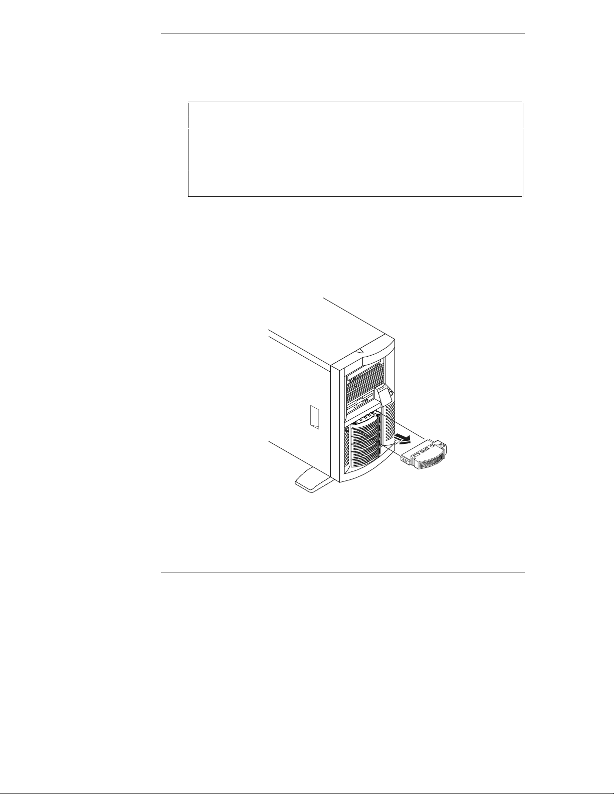
Chapter 4 Installing Mass Storage Devices
Install ing Hot S wap H ar d D rive s
Use this section to install Hot Swap hard drives in the Hot Swap drive cage.
CAUTION Protect the drive from static electricity by leaving it in its
anti-static bag until you are ready to install it. Before handling
the drive, touch any unpainted metal surface to discharge
static electricity. When you remove the drive from the
anti-static bag, handle it only by the frame.
Do not touch the electrical components. Pla ce the drive on the
anti-static bag whenever you set it down.
1. Unlock the Hot Swap Mass Storage Cage with the key provided before
attempting to remove the drive spacer or filler panels.
2. Remove any filler panels in the desired disk drive location :
a. Press in the locking latch and insert your fingers.
b. Using your fingers, pull the filler plug straight out. See Figure 4-8.
46
Figur e 4-8. Removing Filler Panel from Cage
Page 55

Chapter 4 Installing Mass Storage Devices
Drive Space r
3. Remove any drive spacers, if necessary:
a.Slide the drive spacer back, a fra c t ion of a n inch away from your body
as you face t he front of t he dr ive.
Drive spacers attach to the disk drive module with four small feet.
b. Tilt up the front of the drive spacer to disengage the front two feet.
c. Pull the drive spacer forward slightly to disengage the back two feet
and lift. See Figure 4-9.
Figure 4-9. Removing the Drive Spacer
47
Page 56

Chapter 4 Installing Mass Storage Devices
CAUTION To pr event sn ap p in g off the hand le do not use extreme for ce
when op en ing it. Open th e handle until you feel resist ance.
4. Open th e drive modul e b y pressing in on the locking latch at the end of th e
drive ejector handle and pulling the handle open.
Locking tab pivots
when t he ejector
handle is open
Light Pipes
(fragile)
Drive ejector handle
48
Locking Latch
Figure 4-10. Rea dyin g D r ive for Installat ion
Page 57

Chapter 4 Installing Mass Storage Devices
CAUTION Use caution when handling the drive to prevent damage to the
fragil e ligh t pipes as you insert th e drive.
5. Gent ly slide the dr ive module into the cage and stop when you feel
resi stance. See F igure 4-1 1 .
Figure 4-11. Inserting the Drive
6. Verify the pin behind the pivot end of the handle en gages the hole in the
edge of the cage.
7. Press the ejector h andle in until you feel t he latch click into place.
Closing the eject or handle engages the drive with the electrica l connector
in the Hot Swap drive ca g e and seat s the drive.
8. If the drive is unseate d in the cage after closing the ejector handle, re peat
this procedure from Steps 4 to 7.
The hand le was proba bly not pulled out far enough, and the locking latch
failed to engage the Hot Swap mass storage cage.
NOTE Closin g the ejector handle en ga g es the drive wit h the electrical
conn ector in the Hot S wap mass st orage cage and seats th e
drive.
49
Page 58
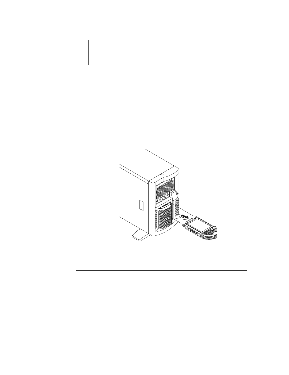
Chapter 4 Installing Mass Storage Devices
Removing Hot Swap Hard Drives
CAUTION You must remove the drive slowly to ensure the drive heads
are parked prior to removal. En sure you follow these
instructions carefully to prevent handling damage, such as
head slaps or head actuato r unlocking.
1. To unlock the drive, push the locking latch in and then pull the ejector
handle toward you. See Figures 4-10 and 4-12.
2. Gentl y pull the drive out about an inch to disengage the power connection.
3. Wait about 30 secon ds for the drive to stop spinning and the drive heads to
park.
4. Use your hand to support the bottom of the drive, while you slowly pull the
drive straight out.
Do not allow the drive to fall.
5. Place the drive in an electrostatic-protected contain er.
Do not stack drives.
50
Figure 4-12. Hot Swap Drive
Page 59

Chapter 4 Installing Mass Storage Devices
Installing Non-Hot Swap Storage Devices
Use thi s section to install any of the non -hot swap mas s s torage devi ces u s ed as a
hard drive or a tape backup storage.
CAUTION Protect the drive from static electricity by leaving it in its
anti-static bag until you are ready to install it. Before handling
the drive, touch any unpainted metal surface to discharge
static electricity. When you remove the drive from the
anti-static bag, handle it only by the frame.
Do not touch the electrical components. Pla ce the drive on the
anti-static bag whenever you set it down.
Non-Hot Swap
Drives
(Optional)
Figure 4-13. Non-Hot Swap Drive Shelves
To install a drive in the non -hot swap drive bay, refer to the following procedure.
1. If n ecessary, shutdown the HP NetServer’ s NOS.
Refer t o Chapt e r 2, "C ontrols, P orts, and Indic ator s ."
2. Discon nect all telephon e ca bles and power cords.
51
Page 60

Chapter 4 Installing Mass Storage Devices
3. If working on a pedestal-mounted NetServer, remove the bezel and gain
access to the HP NetServer’s non-hot swap-drive bays.
Refer t o Chapt e r 3, "Openi ng and Closi ng the HP NetServer."
4. If w orking on a rack-mounted NetSe rver , follow the ap propriat e
instructions to safely extend the NetServer from the rack.
Refer t o Chapt e r 3, "Openi ng and Closi ng the HP NetServer."
5. Select an available drive bay for the device and remove the filler panel.
6. Confi g ure the device accord ing to th e man u facturer ’ s instructions.
Refer to SCSI addres sing in th e " Mas s Storage Gui delin es" s ection ear lier
in this ch ap ter.
7. If you ar e installing a boot devi ce, c heck t he boot priority described e ar lier
in this ch ap ter.
8. If the device does not already have a storage tray or mounting hardware,
inst all the appropriate mounting hardwar e on the device.
Refer to the directions included wi th the device’s mounting hardware.
9. Slid e the drive into the open shelf and secu re th e drive using the two
mounting screws included with the mounting hardware or filler panel.
10. Connect the power cable and the appropriate data cable (SCSI) from the
system board or SCSI controller to the device.
11. Repla ce the cover.
Refer t o Chapt e r 3, "Openi ng and Closi ng the HP NetServer."
12. If the NetServer is rack mounted, slide it back into the rack and secure it.
Refer t o Chapt e r 3, "Openi ng and Closi ng the HP NetServer."
13. Replace the bezel.
Refer t o Chapt e r 3, "Openi ng and Closi ng the HP NetServer."
14. Return power to the NetServer and run the Setup Utility to configure the
device.
52
Page 61

Chapter 4 Installing Mass Storage Devices
Connecting External SCSI Devices
The HP NetServer may provide an external SCSI connector (op tional) at the rear
panel knockout as shown in Figure 4-14. The external SCSI connector is typically
conn ected to a PCI SC SI disk controller boa rd inser ted in one of th e PC I slots.
An external SCSI connection may also be provided by a SCSI disk controller
board or a DAC boa rd insert e d int o one of t he PCI slot s as sh own in Figure 4-14.
The last device in the SCSI chain of external devices must be terminated. See
Figure 4-14.
CAUTION Do not use high voltage differential (HVD) SCSI devices on
any of th e S C S I chan nels or dam age will occur. The HVD
SCSI devices are not supported. Use only Single-Ended (SE)
or Low-Voltage Differential (LVD) devices to connect to the
external connectors.
SCSI Drive
Controller Board
(Optional)
Figure 4-14. External SCSI Connection
53
Page 62

Page 63

5 Installing Additional Memory
Introduction
This chapter provides the instructions for installing and removing DIMMs on the
system board in the HP NetServer LC 2000 or LC 2000r. The video memory
comes with 2MB standard and cannot be upgraded.
NOTE Th e E DO DIMMs and PC 100 SDRAM DIMMs from earlier
HP NetServer models will fit into the DIMM slots in the
NetServer LC 2000/LC 2000r, but the EDO DIMMs and PC
100 SDRAM will not function properly. Use only 133 MHz
SDRAM DIMMs acquired from HP.
To ensure you have the correct DIMMs before in sta llation, refer to one of the
following for a list of quali fied DIMMs:
• Technical Reference Label i nside the HP NetServer’s top or side cover
• HP Order Assistant on the HP web site at:
http://www.hp.com/go/netserver
• Information Assist ant on the HP NetServer Online Documentation
CD-ROM
• HP Customer Service
Tools Requ ir ed
l
An anti-static service kit (3M™ 8501/8502/8503 or equivalent). This kit
includes a static-dissipating work surface, a ch assis clip lead, and a wrist
strap.
55
Page 64

Chapter 5 Installing Additional Memory
Memory In stallation Guideline s
• The HP NetServer LC 2000/2000r uses only 133 MHz (PC133) SDRAM
DIMMs, which are electrically different from the EDO and PC100
SDRAM memory modules used in previous HP NetServer models.
• DIMM sizes supported are 64 MB, 128 MB, 256 MB, 512 MB, or 1 GB in
any combination.
• Supported memory capacity ranges from 64 MB to 4 GB maximum (1 GB
per DIMM slot and 4 DIMM slots total). The minimum capacity is 64 MB
(one DIMM).
• DIMM sizes may be mixed on the system board and may be loaded in any
order (0 through 3).
• Open slots between DIMMs are permitted.
• When handling DIMMs, obser ve anti-static preca uti ons to avoid damage.
DIMM Insta llat ion
Use this procedur e to install ea ch DI MM in a DIMM slot on the system board.
56
Figure 5-1. Individual SDRAM DIMM
CAUTION Do not in stall E DO DIMMs or PC100 SDRAM from previous
HP NetServers in the HP NetServer LC 2000/2000r. Use only
DIMMs specified for the HP NetServer LC 2000/2000r.
Page 65

Chapter 5 Installing Additional Memory
To install addition al memory in the HP NetServer, refer to the following
procedure.
1. To gain access to the HP NetServer, perform one of th e procedures listed
below.
NOTE It is not necessary to remove the system board from the
HP NetServer to install the additional DIMM memory.
◊ If the NetServer is mounted on the pedestal, perform Steps 1-8 in the
"Removing Covers – Pedestal (LC 2000)" in Chapter 3, "Opening and
Closing the HP NetServer," to gain access to the NetSer ver.
◊ If the NetServer is in th e ra ck, perform steps 1 -1 4 in the "Removin g
Covers – Rack Mount (LC 2000r)" in Chapter 3, "Opening and Closing
the HP NetServer," to gain access to the NetServer.
2. Locate the DIMM slot for installation and spread the two retaining clips
outwar d to accept the DIMM. See Figure 5-2.
3. Remove the HP DIMM from its container, handling the module by its
edges.
If you must lay it down, place it on an anti-static mat.
Figure 5-2. Opening Retaining Clips
4. Align the notches on th e DIMM with the keys on the DI MM slot, h oldin g
the DIMM at a 90° angle to the system board. See Fig ures 5-2 and 5-3.
57
Page 66

Chapter 5 Installing Additional Memory
5. Insert the DIMM fully into the slot, han dling the DIMM by its edges. See
Figures 5-2 and 5-3.
The retaining clips should grasp the DIMM automatically if it is inserted
proper ly. If th e clips do not close, the DI M M i s n ot inserted correct ly.
CAUTION Do not rock the DIMM int o place, but ap pl y firm and even
pressure. If the retaining clips do not close, remove the DIMM
and r ep eat Steps 2- 5.
58
Figure 5-3. I nst al li ng the DI MM
NOTE The Processor Cage Cover is shown removed for clarity.
6. If all DIMMs have been instal l ed, r epla ce th e cover .
Refer t o Chapt e r 3, "Openi ng and Closi ng the HP NetServer."
Page 67

Chapter 5 Installing Additional Memory
7. If the NetSe rver is in a rack installation, retur n the chass is into the ra ck.
Refer t o Chapt e r 3, "Openi ng and Closi ng the HP NetServer."
8. Re-install the bezel onto the front of the HP NetServer.
Refer t o Chapt e r 3, "Openi ng and Closi ng the HP NetServer."
9. Reconnect the power cord(s).
10. Power on the HP NetServer according to the respective NOS power-up
instructions.
Refer t o Chapt e r 2, "C ontrols, P orts, and Indic ator s ."
11. Return the HP NetServer to nor mal operation.
DIMM Removal
Use this procedure to remove DIMMs from the HP NetServer’s system board. The
HP NetServer must be powered down and the appropriate cover must be removed
from the HP NetServer before r emoving any DIMMs.
1. If you ha ve not a lrea dy removed the appropriate cover from the HP
NetS e rver, p erfor m one of the procedures listed bel ow.
◊ If the NetServer is mounted on the pedestal, perform Steps 1-8 in the
"Removing Covers – Pedestal (LC 2000)" in Chapter 3, "Opening and
Closing the HP NetServer," to gain access to the NetSer ver.
◊ If the NetServer is in th e ra ck, perform steps 1 -1 4 in the "Removin g
Covers – Rack Mount (LC 2000r)" in Chapter 3, "Opening and Closing
the HP NetServer," to gain access to the NetServer.
2. Select the desired DIMM(s) to remove.
3. Open the DIMM's retaining clips to lift the DIMM’s top edge away from
the clips. See Figure 5-4.
4. Lift the DIMM completely away from the slot. See Figur e 5-4.
5. Place the DIMM in it s an ti-stat ic container.
59
Page 68

Chapter 5 Installing Additional Memory
Figure 5-4. Removing a DIMM Module
6. Repeat Steps 2 through 5 to remove any additional desired DIMMs on the
system board.
NOTE Ensure the retaining clips on the DIMM slots for ea ch DIMM
are closed be fore r ep lacing the cover onto the HP NetServer.
An error will be displayed if all DIMMs are removed.
7. If all desired DIMMs have been removed, replace the cover.
Refer t o Chapt e r 3, "Openi ng and Closi ng the HP NetServer."
8. If the NetServer is a rac k install ation, return the chassis into the rack.
Refer t o Chapt e r 3, "Openi ng and Closi ng the HP NetServer."
9. Re-install the bezel onto the front of the HP NetServer.
Refer t o Chapt e r 3, "Openi ng and Closi ng the HP NetServer."
10. Reconnect the power cord(s).
11. Power on the HP NetServer according to the respective NOS power-up
instructions.
Refer t o Chapt e r 2, "C ontrols, P orts, and Indic ator s ."
12. Return the HP NetServer to nor mal operation.
60
Page 69

6 Installing Additional Boards
Introduction
This chapter describes how to install accessory boards into the system board of the
HP NetServer LC 2000/2000r. The system board provides up to six PCI slots
(P1 through P6), two of which are 64-bit slots.
Tested PCI Boar ds
For a list of tested PCI boards, ch eck for compa tibility in Configuration Assist ant
on the Navigator CD-ROM or look for the Hardware Tested Products list for the
HP NetServer LC 2000/2000r under the Service and Support topic for the specific
NOS used in the NetServer at HP’s web site:
http://www.hp.com/netserver/support/compatibility
CAUTION Some a ccessory board outputs ma y exceed U.S. National
Electrical code (NFPA 70) Class 2 or limited power source
limi ts and must use appropri ate interconnecting cabl ing in
accord ance with the National Electr ical Code. (All
Hewlett-Packard boards comply with Class 2.)
Tools Requ ir ed
The foll o wing tools are required for installation or removal of th e acces sori es
boards in the HP NetServer LC 2000/2000r:
• An anti-static service kit (3M™ 8501/8502/8503 or equivalent). This kit
includes a static-dissipating work surface, a ch assis clip lead, and a wrist
str ap with gr ound le ad.
Remote Control Card
The HP NetServer LC 2000/2000r may use the HP TopTools Remote Control card
in any PCI slot on the system board. The Remote Control card supports HP
TopTools software. An I
information on use of the HP TopTools Remote Control function, see Ch apter 11,
"Information Assist ant , " and Chapter 10, "Config urin g the HP NetServer."
2
C connector is provided on th e sys tem boar d. For more
61
Page 70

Chapter 6 Installing Add itio nal Boar d s
Boot Priority
This section details the HP NetServer’s boot order by highest to lowest priority.
The NetSe rver’s bo ot order ( BIOS sea rch order for a bo ot drive) s hould be
considered when selecting a slot on the system boar d. This is especially important
if you are i nstalling a SCS I disk controller board. The disk controller’s boot
priority is set by the boar d’s slot location. See Figure 6-1.
The on-board SCSI consists of two channels, A and B. Channel A is typically
used to control the Hot Swap SCSI drives. Channel B is typically used to control
the int ernal non-hot swap S C S I dr ives. On each S C S I channel, th e s yst em scans
for a boot de vice starting a t device ID 0 and wor ks up from t here.
By defaul t th e Ne tServer s e a rche s for boot devices in th is ord er:
1. IDE CD-ROM drive
2. Flexible disk drive
3. SCSI A bus (typically the Hot Swap Mass Storage Cage)
4. SCSI B bus (typically the non- Hot Swap int ernal SCSI devices)
5. PCI slot P1
6. PCI slot P2
10. PCI slot P6
62
7. PCI slot P3
8. PCI slot P4
9. PCI slot P5
NOTE The NetServer can be configured to boot fr om a P C I a cces s ory
board or PCI-based DAC, instead of the onboard SCSI
channe ls, by pu tting the boar d in on e of the PC I slots. Th e
SCSI Con figuration Utility can be used to configure the
NetServer to ski p over the onboard SC SI channels and select a
PCI slot inste ad, when scanni ng for boot devices . For
instructions, refer to the SCSI Con figuration Utility in Chapter
10, "Configuring the HP NetServer."
Page 71

Chapter 6 Installing Add itio nal Boar d s
IRQ Settings
The IRQ settings are automatically assigned and don’t require user intervention.
PCI boards have the capability of sharing hardware interrupts (IRQs) with other
PCI boards, as stated in the PCI specifications, but this does not always prove to
be true between board manufa c turers. To solve th is problem requi res an in- depth
knowledge of a server’s implementation to place a PCI board in a slot that would
not conflict with another PCI board’s IRQ setting.
The HP NetServer provides various ways to automatically share interrupts in the
NetSer ver. The sharing mode can be select ed u nder th e h eading "Sharing
Algorithms" in the Setup Utility. The IRQs are automatically assigned during boot
up for each PCI slot and embedded device in the NetServer, avoiding any IRQ
conflicts and providi ng th e be s t performan c e. This feature a lso provide s a wa y of
manually assigning IRQs when disabling the Sharing Algorithm feature. Refer to
Chapter 10, "Configuring the HP NetServer," for more information.
These IRQ assignments tri g g er the instal l ed NOS to enable t he APIC (Advan ced
Programmable Interr upt Controller) which takes control of the IRQ sharing
scheme. You are not required to manually assign interrupts for the following
NOSs:
l
Microsoft’s NT 4.0
l
Novell’s NetWare 5
l
SCO UnixWare 7
NOTE SCO Un i x War e 7 requires in stall at i on of the OSMP module to
enable the APIC mode.
System B oard PCI Sl ots
All accessor y boards plu g into the six sl ot s on s yst em board at the rear of th e
NetServer’s cha ssi s. See Fig ur e 6- 1.
• Four PCI slots (P1-P4) support full length 32-bit boards at a clock rate of
33 MHz. These slots only support +5 VDC power and Universal boards.
These slots have keys in the up per ha lf of the boa rd sl ot to pr eve nt 3.3 volt
boards from being inserted into the slots.
NOTE Un iversa l boards automati cally switch to accept po wer from a
+5.0 or +3.3 VDC source and have a key slot in the connector
to allow installation in any of the 6 PCI slots.
63
Page 72

Chapter 6 Installing Add itio nal Boar d s
Switch
• Two PCI slots (P5-P6) suppor t full-length 32- or 64-bit boards at clock
rates of 33 MHz . These slots only support +5 VDC power and Universal
boards. These slots have keys in th e upper half of the board slot to prevent
3.3 volt boards fr om being ins e rted into the sl ots.
CAUTION Some a ccessory board outputs ma y exceed U.S. National
Electrical code (NFPA 70) Class 2 or limited power source
limi ts and must use appropri ate interconnect cabling in
accord ance with the National Electr ical Code.
• I/O connections – The system board provides connections to support the
video monitor, mouse, keyboard, one serial port, one management port,
one parallel port, and an embedded NIC por t.
TopTools I C C onnect or
2
IDE
CD-ROM
SCSI B
Front Pa nel Control
SCSI A
Flexible
Disk
Drive
64
12345
Slots P1-4
32-bit
33 MHz
Slots P5-6
64-bit
33 MHz
6
Configuration
Figure 6-1. System Board PCI Slots
Page 73

Chapter 6 Installing Add itio nal Boar d s
Closed = On
Open = Off
2 Proces sor Speed (Bit 1)
3 Proces sor Speed (Bit 2)
4 Proces sor Speed (Bit 3)
5 Clear Configuration
6 Clear Password
Shaded rect angle
represents the
position of slide
switch.
Figure 6-2. Configuration Switch Block
Rear of HP NetServ er
Installing Accessory Boards
Use thi s procedur e to install all acces sor y boards.
1. Read the documentation included with each board and follow any special
ins t ruction s provided .
CAUTION To pr event a system crash, n ever remove or insert a PCI board
from or into a sl ot with the N e tServer p ow e red on. Al ways
turn power off to the NetServer before performing any
installation or removal operations.
2. Log off all users and back-up all files.
3. Follow the instru ction s in the respective NOS (network operating system)
documentation to gracefully shut down all networking software and
applications.
4. Press the power button on the HP NetServer’s control panel when
pr ompted by the operating system.
8 FSB Speed (133/100 MHz)
Normally, this completes the shutdown procedure.
NOTE The power supplies will continue to provide standby current to
the Net Server until the p ower cable is dis connected .
65
Page 74

Chapter 6 Installing Add itio nal Boar d s
5. Gain a cces s to the Net S erver by performin g the appropr iate procedure for
the NetServer LC 2000 or the LC 2000r.
◊ If the NetServer is mounted on the pedestal, perform Steps 1-8 in the
"Removing Covers – Pedestal (LC 2000)" in Chapter 3, "Opening and
Closing the HP NetServer," to gain access to the NetSer ver.
◊ If the NetServer is in th e ra ck, perform steps 1 -1 4 in the "Removin g
Covers – Rack Mount (LC 2000r)" in Chapter 3, "Opening and Closing
the HP NetServer," to gain access to the NetServer.
6. Consider the boot priori ty before in stallin g any accessory board s .
See Figure 6-1.
If installing a SCSI disk controller board, the controller’s priority (BIOS
search order for a boot drive) is set by the board’s slot location. For details,
refer t o Boot Priority ea rli er in this chapter.
7. Identify the desir ed slot (P1 through P6), before instal ling the accessory
board. See Figure 6-1.
66
Page 75

Chapter 6 Installing Add itio nal Boar d s
8. Remove the slot cover from the NetServer’s rear panel, before installing
the new board into the slot, as shown in Fi g ure 6-3.
2. Li ft Latch
3. Remove Slot Co ver
1. Open T ab
Figure 6-3. Removing the Slot Cover
NOTE Each P CI slot mus t have a slot cove r or PCI board in the s lot.
Ens ure all unused slots have s lot covers i n pla c e .
CAUTION Do n ot bend the PC I board to inst all it into the slot. If a
full-length PCI board has a handle on the end of the board that
prevents its installation , remove the handle before installing
the boar d.
67
Page 76

Chapter 6 Installing Add itio nal Boar d s
9. Before installing the new PCI board:
◊ Verify there is no handle attached to it, especially if it is a full-length
board.
◊ If it has a handle attached, remove the handle before installing the
board into the slot.
NOTE Use only the right si de of th e two slots in the board guid e,
when installin g PCI boards int o some of the PCI slots
(P3 through P6) on the system board.
10. Align the board with its slot along its full length and position it into the
slot.
11. Push the PCI boar d d own in to its conn ector in th e S ystem board.
68
Page 77

Chapter 6 Installing Add itio nal Boar d s
1. Insert Board
2. Close Latch
3 . Turn Tab
Figure 6-4. Installing the Accessory Board
12. Secure the PCI board as shown in Figure 6-4.
13. If the installed accessory board requires an external connection or a
connection to the System board, en sure the cable is properly attached.
Refer to the accessory board documentation for connection requirements.
14. If accessor y board insta llation is compl ete, re-in st all the cover on the
NetServer.
Refer t o Chapt e r 3, "Openi ng and Closi ng the HP NetServer."
15. Re-install the bezel onto the fron t of the HP NetServer.
Refer t o Chapt e r 3, "Openi ng and Closi ng the HP NetServer."
69
Page 78

Chapter 6 Installing Add itio nal Boar d s
16. If all installation work is complete, return power to the NetServer
according to the respecti ve NOS power u p instru ct i on s.
17. Use the respective NOS softwar e t o en sur e the correct softwar e dr i ver s for
the PCI boa r d ar e loaded an d verify correct oper ation.
70
Page 79

7 Installing Additional Processors
Introduction
The HP NetServer LC 2000/2000r supports two processors in primary and
second ary slots and both pr ocessors m ust operate at the sam e speed and cache
size.
The HP NetServer supports the Pentium III processors at a front side bus (FSB)
speed of 133 MHz. Advanced processors will be supported as each one becomes
available. Contact HP or your reseller for details.
The Net Server ships with on e pr ocessor in the primary process or slot an d one
voltage regulator module (VRM) installed its respective VRM slot. Both
processors and VRM slots are l ocated on th e system board.
Tools Requ ir ed
• An anti-static service kit (3M
includes a static-dissipating work surface, a ch assis clip lead, and a wrist
strap.
8501/8502/8503 or equivalent). This kit
Processor Configu ration Gu idelin es
The HP NetServer LC 2000/2000r supports a variety of processor speeds with an
FSB speed of 133 MHz.
CAUTION Do not open the new processor ’s protective bag or rem ove it
from the bag until you are ready to install it.
Before you remove a processor from the anti-static container,
touch a grounded, unpainted metal surface on the HP
NetServer to discharge static electricity.
• Both processor modules must be the same processor type and have the
same product number, which insures the same clock speed, cache size, and
FSB speed.
• The processor modules must operate at th e d es ignated s p eed s tated by th e
product type on the processo r.
71
Page 80

Chapter 7 Installing Additional Process ors
Switches
CAUTION Do n ot s et the processor speed swi tches t o any other speed, as
this can re s u lt in un re liable o r i ntermittent perf ormance, and
data integrity may also be at risk.
l
Use only processor upgrade kits with the same HP product number. This
ensur es the processor type, cl o ck s p eed , and ca ch e s ize match, an d th at
product n u mbers a re compatible.
l
Ensur e you install the proces sor module and it s resp ective VRM in the
secondary slot, if the primary processor is already installed.
Auxiliary Fan Power Connectors
Secondary
Processor Slot
3
Primary
Processor Slot
0
12
Jumper 1
(Factory Set)
72
2nd VRM
1st VRM
12345
6
Configuration
Figure 7-1. System Board
Page 81

Chapter 7 Installing Additional Process ors
Installing the Processor
The installation procedure is the same for the rack-mounted models as for the
pedestal models of the NetServer once you gain access to the system board.
CAUTION Use an anti-static wrist strap and a grounding mat.
Wear a wrist-strap and use a static-dissipating work surface
conn ected to th e cha s sis when handling com p onents. En sure
the metal of the wrist strap contacts your skin.
1. Unpa ck the processor ship ping box and ch eck the conten ts again st its
packing list .
CAUTION Do not remove the processor from i ts bag unti l you are read y
to install it an d ensure the bag remain s sealed until then.
2. Gracefully sh u t d own the networ k operating system according to direct ions
in your NOS documentation.
3. Press the power switch on th e HP Net S erver’s control panel when
pr ompted by the operating system.
Normally, this completes the shutdown procedure.
4. Disconnect the power cord or power cords.
WARNING Power supplies will continue to provide standby current to the
NetSer ver unti l the power ca bl es are disconnected.
5. To gain access to the system board, follow the appropriate instructions for
removing the cover.
◊ If the NetServer is mounted on the pedestal, perform Steps 1-8 in the
"Removing Covers – Pedestal (LC 2000)" in Chapter 3, "Opening and
Closing the HP NetServer," to gain access to the NetSer ver.
NOTE It is not necessary to remove the system board from the
NetSer ver to in st al l the new processor mod u le or the VRM.
◊ If the Net Server is in the rack, perform st ep s 1 -1 4 in th e " Rem ovi ng
Covers – Rack Mount (LC 2000r)" in Chapter 3, "Opening and Closing
the HP NetServer," to gain access to the NetServer.
73
Page 82

Chapter 7 Installing Additional Process ors
Open = Off
Rear of HP NetServer
6. Verify the processor speed an d FSB settin g, before in sta ll ing the second
processor module. See Figures 7-1 and 7-2, and Tables 7-1 and 7-2.
Both pr ocessor m odules must have the same clock speed, cach e size, FSB
speed, and produ ct number.
7. If installing two new processor modules, set the switches accordingly.
Use a small, flat-blade screwdriver or similar tool.
Closed = On
2 Processor Speed (Bit 1)
3 Processor Speed (Bit 2)
4 Processor Speed (Bit 3)
5 Clear Configuration
6 Clear Password
Shaded rectangle
repr esents the
position of slide
switch.
Figure 7-2. System Switch and Settings
Table 7-1. Configuration Switch Settings
FSB Switch Setting
SW8 – Off
(133 MHz Bus)
(Multiple
of FSB)
Processor Speed Settings
SW1 SW2 SW3 SW4
533 MHz 4.0X ON OFF ON ON
600 MHz 4.5X ON OFF ON OFF
667 MHz 5.0X ON OFF OFF ON
733 MHz 5.5X ON OFF OFF OFF
8 FSB Spe ed (133/100 MHz)
74
Page 83

Chapter 7 Installing Additional Process ors
NOTE Some processor speeds listed in Table 7-1 may not be supported. For the
latest support information, visit the HP web site:
http://www.hp.com/go/netserver
NOTE The System b oard is shown r emoved from t he HP Ne tServer
for simplicity in the following figures, but it is not necessary to
remove t he system board to ins t all the new processor m od u le
or the VRM.
8. Loosen the thumbs c rew on the proces sor c age cover, and lift off t he cover
as shown in Figure 7-3.
Processor Cage
Cover
Figure 7-3. Removing Processor Cage Cover
75
Page 84
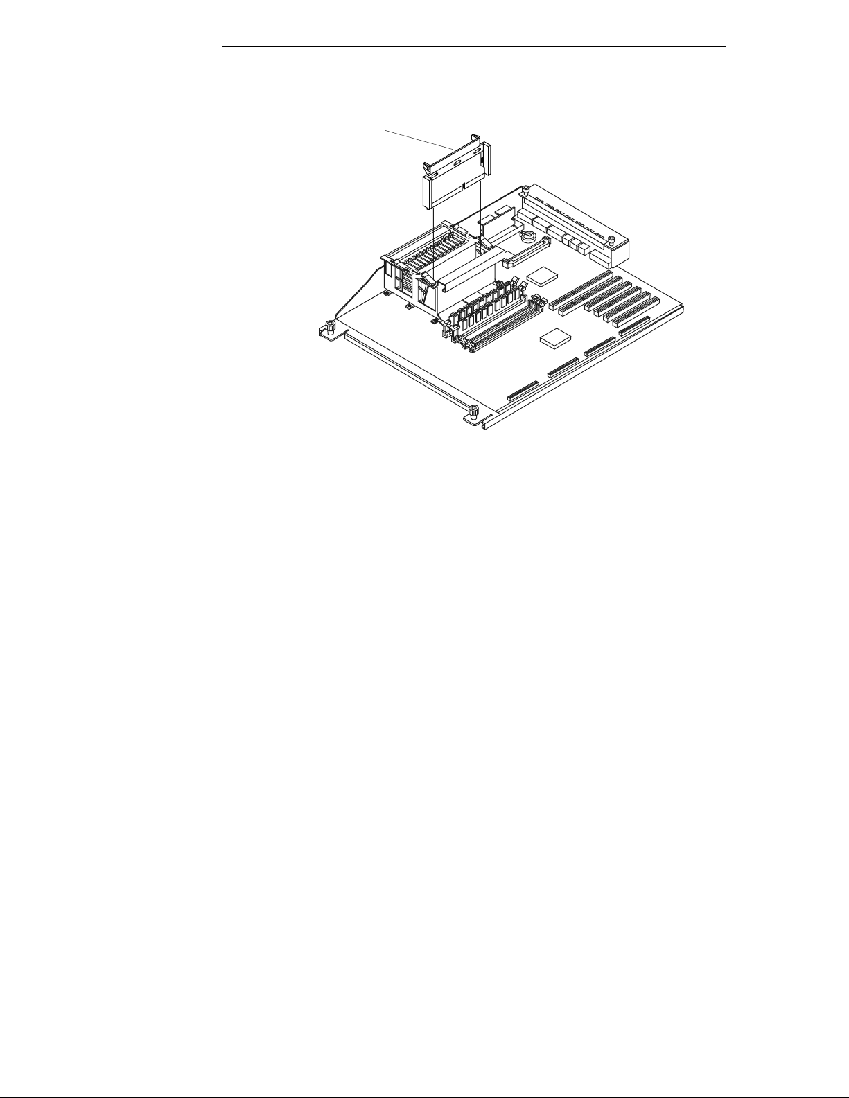
Chapter 7 Installing Additional Process ors
9. Remove t he termination from the secondary processor s lot by pressi ng in
on the tabs and pulling directly upwards. See Figure 7-4.
Terminator
76
Figure 7-4. Remove Terminator Board
Page 85

Chapter 7 Installing Additional Process ors
10. Remov e t he processor module from th e s ealed bag.
11. Open the lat ch es on top of the pr ocessor sl ot . S ee Figure 7 - 5.
If a processor is installed in the slot, the processor module will move up in
the slot where you can grasp it for removal .
Figure 7-5. Installing the Processor
12. Ali gn the additi onal proces sor module over th e s econdary processor
module slot. See Figure 7-5.
13. Gently push down on the processor module until it seats.
14. Slide the retaining latches closed to completely seat the processor module
firml y in the conn ect or . See Figure 7-6.
77
Page 86

Chapter 7 Installing Additional Process ors
VRM
Latches
2nd VRM
Figure 7-6. I nst al li ng VRM
CAUTION To pr event damage to the VRM, do not push on the large fl at
surfa ce or touch the componen ts on the board as you push the
VRM card down into the slot. Pu sh only on the edges of the
VRM board.
15. Open the VRM retaining latches as shown in Figure 7-6.
16. Ali gn the VRM’s con nector edge with the s econdar y VRM slot .
See Figure 7-6.
The VRM’s component side should face towards the center of th e
enclosure, wh ich is just the opposite of the primary VRM already in stalled.
17. Gentl y push as you insert the VRM into the socket. See Figure 7-6.
18. Re-insta ll the cover on the pr oc essor cage by rev e rsing Step 8.
19. Re-insta ll the cover and be zel onto t he Net Serve r according t o t he
appr opr iate pr ocedu re.
Refer t o Chapt e r 3, "Openi ng and Closi ng the HP NetServer," for
instructions.
20. Return power to the NetServer and restore normal operation.
78
Page 87

8 Rack Mounting the HP NetServer
s
o
/
/
ks:
V
e
y
s
Sys
e
E
I
o
t
orB
Introduction
This chapter tells how to mount the HP NetServer in an HP System/E or System/U
rack. The illustration below shows the characteristics of the System/E and
System/ U racks. I f you have the old er HP Systems r ack, see Chapter 13,
"Alternative Rack Mounting," for instructions. (If you are mounting the NetServer
in a non-HP rack, refer to the separate rack-mounting guide for third-party racks.
It is pack ed in the accessories tray in th e HP NetServer’s shipping box.)
a
b
c
e
Figure 8-1. HP System/E and System/U Rack Features
Charact eristi c
System
System
a. 5-Cornere dColumns
d
b. Full Panel
c. "HP Rack S
d. Numbered
e. Anti-Tip Fo
Eand
URac
"HP R ack
Name Plat
Out Front
f
nt
tem/E" or
tem/U"
AUnits
Extends
ack
79
Page 88

Chapter 8 Rack-Mountin g the HP Net Serv er
NOTE If you want to put your NetServer into a third-party rack not
mentioned in the guide, you may be able to find relevant
documentation on HP’s web site at the following URL:
http://www.hp.com/netserver/support
The HP NetServer r ack mount kit requir es five EIA uni ts of space in the rack.
Before mounting the NetServer, plan the NetServer’s location in the rack relative
to other rack components. Proper placement is vital both for safety and operating
efficiency. For more deta ils, see the HP Rack Installation Road Map and the HP
NetServer LC 2000r Rack Cabling Reference Guide.
NOTE If the HP NetServer is completely configured by the vendor
before delivery to the customer, then mounting the HP
NetServer in the rack may be the final step in the installation
procedu re. If th e vendor con fi g ures the HP NetServer at the
customer’s site, installation of the network operating system
and other software may occur after the HP NetSer ver is
mount ed in the rack.
WARNING The HP NetServer weighs 80 lbs. (36 kg) fully loaded. To
prevent an acci d en t, use two peopl e when pl a cing the
NetSer ver into the rack.
CAUTION If other ra ck component s are to be mount ed in the rack below
the HP NetServer, install those comp onents before starting t o
mount the NetServer.
Tools Requ ir ed
To assem bl e the rack mount kit and install the HP NetServer on it, you need th es e
tools.
• T-15 and T-25 Torx Drivers
• Number 2 Phillips screwdriver
l
Marking pen
80
Page 89

Chapter 8 Rack-Mountin g the HP Net Serv er
Safety Pr ecauti ons
Always keep the following safety and environmental issues in mind, especially if
you install th e HP NetS erver in a non-HP rack environ ment:
l
Optimum Operating Environment – The optimum operating conditions
for the HP NetServer is in an environmental controlled computer room
with a temperature range of 20 to 22°C (68 to 72°F) at 40 to 60% relative
humidity.
• Maximum Ambient Temperature - Ensure the maximum ambient
temper ature does not exceed 3 5°C (95° F).
• Elevated Operating Ambient Temperature - The ambient operating
temperatur e within a closed or multi-unit rack assembly is likely to exceed
the room's ambient temper ature. En s ure the temp er ature wit hin the rack
itsel f d oes not exceed 35°C (95°F).
• Reduced Air Flow - As you moun t eq u ipment in the rack, ensure you
allow enough air fl ow for safe operation of the equipment. The NetServer's
fans will only operate correctly if both front and rear door s of the rack
allow free air flow (perforated openings), or are removed.
• Mechanical Loading - Uneven m echanical loading within the ra ck can
cause hazardou s conditions. To prevent this in your installation plans ,
place the heaviest components in the bottom of the rack, mounting all
components as lo w in the rack as is p rac tical.
• Circuit Overloadin g - Ensure the total configuration of equipment in the
rack does not overload the supply circuit. To this end, check the nameplate
ratings on all equipment. Consider the effect of circuit overloading on
overcurrent protection and supply wiring.
• Reliable Earth Grounding - Maintain rel iable earth groundi ng of
rack-mounted equipment. Give particular attention to supply connections
that ar e not direct connecti ons to the branch circu it: for ex ample, using
non-HP power strips.
81
Page 90

Chapter 8 Rack-Mountin g the HP Net Serv er
Preparing the Rack
The colu mn adapt er s an d r a ck n u ts must be conn ected to the rack befor e mounting
the sl ide mechan ism. Once the slides ar e correctl y mounted, then the HP
NetSer ver LC 2000r can be installin g into the rack . A car d boa rd rack mounting
template comes with the HP NetServer. The template iden tifies the column
adapter and rack n ut locations on the r ack.
HP NetServ er Rack M ount P arts List
Ens ure the rac k-mou nting kit provided wi th the HP NetServer c onta i ns the
following parts:
Table 8-1. Parts for Rack Mount Kit
Quantity Description
2 Slides
4 Rack Nuts
12 Rack Nut Screws (M5 x 16mm)
6 Screws for Slides (8-32 x ¼ inch, 4 panhead and 2 flathead)
2 Column Adapters
1 Template
Marking th e Rack and A ttach ing Rack Nuts
Use this section to mark the front columns and attach the rack nuts to the rear
columns of the HP System/E or HP System/U rack. The column adapters attach to
the fr ont columns and the slides are att ached to th e col u mn adapters and the ra ck
nuts to hold the NetServer's slides in place. The rack template and marking pen
are used to identify and mark the locations on the columns.
CAUTION If other ra ck component s are to be mount ed in the rack below
the HP NetServer, install those comp onents before starting t o
mount the NetServer.
NOTE Use the HP Rack Configuration Tools to determine wh ere in
the rack to mount the HP NetServer. The tools are available at:
http: //www.hp.com/netserver/support
82
Page 91

Chapter 8 Rack-Mountin g the HP Net Serv er
1. Find the rack-mounting template.
If your HP NetServer is still in its box, the template should be in the
accessories tray that s its on top of th e NetServer itself.
2. Hold the template alongside the outside face (front) of the left front rack
columns.
3. Lin e up the bottom of the templa te with th e lower line of the NetServer’s
location in the rack.
The template covers a span of 5 EIA units, which is the height requirement
of the HP NetServer.
4. Use the marking pen to mark the 2nd and 14th holes on both front
columns, as sh own on the template. See Figure 8-3.
NOTE The two column adapters are mounted at the 2n d an d 1 4 th
holes on the resp ective front column an d provide th e captive
nuts for mounting the rack slides to the fron t columns at 7th
and 9th holes from the bottom. If you don ’t have the template,
Figure 8-3 sh ows the location on the front columns for the
column adapters.
Figure 8-2. Placing Rack Nuts on Rack Columns
83
Page 92

Chapter 8 Rack-Mountin g the HP Net Serv er
Mark th is face of the
represents
9th Hole
From Bottom
From Bottom
"#"
the EIA unit
numbers on the
rack columns.
Left
Front of
Rack
Right
14th Hole
From Bottom
#
#
#
#
#
Bottom of
2nd Hole
From Bottom
#
HP NetServer
left-fro n t and
right-front columns.
Figure 8-3. Location Marks on the Rack’s Front Columns
5. Turn the template over and us e it to mou n t ra ck nuts (at 7th and 9th holes)
on the left-rear and right-rear rack columns.
The template provides you with the nut placement locations. If you don’t
have the template, Figure 8-4 sh ows rack nut placement for the two rear
rack col u mns.
84
#
Left Right
#
Rear of
Rack
Attach nuts to this face
of the rear columns.
Bottom of
HP NetServer
Figure 8-4. Rack Nut Locations on the Rack’s Rear Columns
#
#
7th Hole
#
represents
"#"
the EIA unit
numbers on the
rack columns.
Page 93
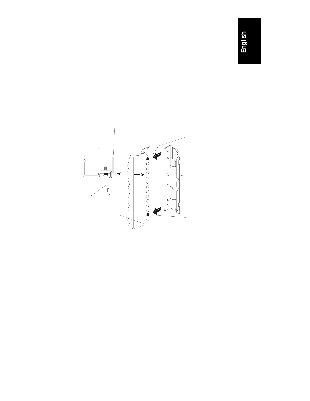
Chapter 8 Rack-Mountin g the HP Net Serv er
2nd Hole
From Bott om
From Bott om
Column
Attachin g the Co lumn A dapters and S lides
1. Pull the anti-tip foot for ward out of the bottom of the rack.
See Figure 8-6 for the anti-tip foot location.
2. Align the left HP column adapter to the left front column as shown in
Figure 8-5.
3. Match the column adapter holes (2nd & 14th) to the marks on the fr ont
column and place the column adapter mounting holes behind the column
face. See Figur e 8 -5 .
4. With the column adapter held in position, insert two screws (M5) through
the holes in the column into the captive nuts on the column adapter. See
Figure 8-5.
5. Repeat Steps 2 through 4 for the column adapter on the right front column.
Slide Mount
14th Hole
Left
Front
Adapter
Column
Adapter
Bottom of
HP NetServer
Figure 8-5. Mounting Column Adapter to Front Columns
6. Hold a slide in position inside the two left-hand rack columns and
observing the following items.
a. The mounting flan g e on each end of the slide mus t wrap around the
outsid e fa ce of both the front and rear columns. See Fi g ure 8-6.
85
Page 94
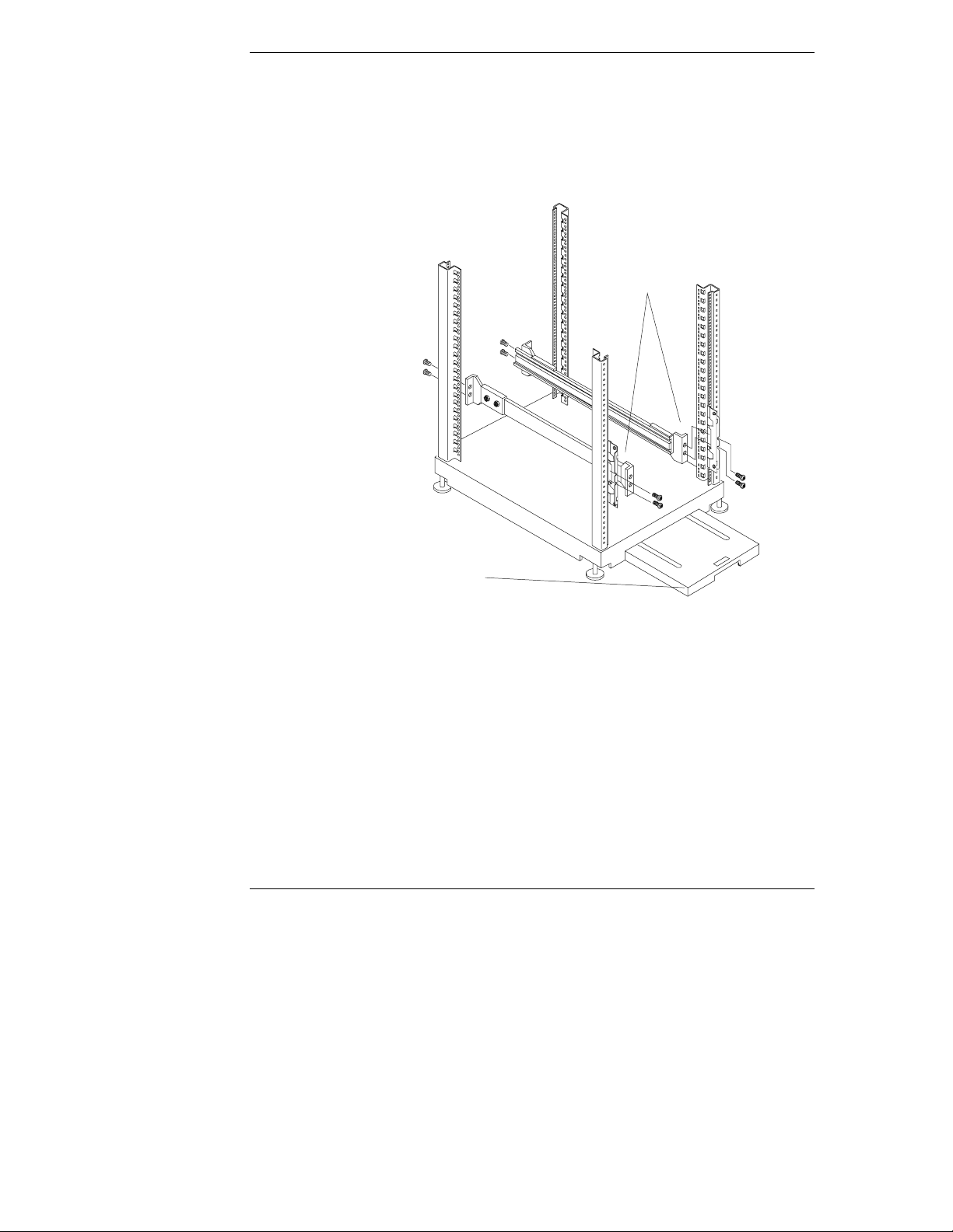
Chapter 8 Rack-Mountin g the HP Net Serv er
Mount Slides
inside Column
b. The two h oles in the mounting flange should line up with the captive
nuts (at 7th and 9th holes) in the column adapter and the two rack nuts
you installed on each rear column.
c. The extending portion of the slide (slide member) should point forward
out of the rack.
Adapters
86
Extend rack’s
anti-tip foot
from front of rack
for s a f ety.
Figure 8-6. Securing th e Slides to t he Rack Columns
7. With the slide pushed firmly into position, insert two screws through the
slide’s front bracket into the captive nuts on the left column adapter.
a. Secure the screws only loosely at first, so the bracket can settle into the
lowest possible position . There is a dimple in the bracket to position
the slides in the proper location.
b. Then tighten the screws until the bracket is held firmly to the column
adapter and rack column. See Figures 8-5 and 8-6.
Page 95

Chapter 8 Rack-Mountin g the HP Net Serv er
8. Fast en the slid e’s rear brack et to the rack nuts on the left- rear col umn.
a. Secure the screws only loosely at first, so the bracket can settle into the
lowest possible position . There is a dimple in the bracket to position
the slides in the proper location.
b. Then tighten the screws until the bracket is held firmly to the column.
9. Attach the other slide to the righ t-front column adapter and right-rear rack
column by repeating Steps 6-8.
Placing the HP N etSer ver in the R ack
Use this procedure to position the HP NetServer into the extended slides and
secure the chas sis to the slides. Once the NetServer is in the rack, th en you ca n
conn ect the Cabl e Management Arm to the r ear of the NetServer.
WARNING To prevent rack instability while mounting the HP NetServer
pull the rack’s anti-tip foot forward out of the bottom. Failure
to do so could result in injury and equipment damage.
To preven t the rack from rolling while you m ou nt the HP
Ne t Server, ensure the leveler screws on t he rack’s lo wer fou r
corn er s are in firm con tact with the floor. S ee F i gure 8-7.
1. Lower the leveler screws on the rack’s lower four corners to make firm
contact with the floor. See Figure 8-7.
2. Ensure you have ext ended th e an ti-tip foot from th e ra ck before cont inuing
this procedure. See Figure 8-7.
87
Page 96

Chapter 8 Rack-Mountin g the HP Net Serv er
Slide Members
Mounting Tabs
Leveler
Screws (4)
Anti-t ip Foot
Figure 8-7. Pulling Out the Slides
3. Pull out both slides until the slide members are fully extended.
See Figure 8-7.
88
The slides click into position when locked. This locked position prevents
the slides from moving back into the rack, unless the release latches are
pressed as shown in Figure 8-10.
4. With the help of at least one other person, lift the HP NetServer by its four
handles off the floor or pallet.
5. Move the rear of the NetServer just beyon d the ext en d ed sl ide member s .
6. Position the NetServer’s channels on each side to insert the slide members
into the channels. See Figur e 8-8.
The mounting tabs in the sli d es wi ll engag e the slots in th e ch assis.
See Figure 8-7.
Page 97

Chapter 8 Rack-Mountin g the HP Net Serv er
Channel(2)
Figure 8-8. Mounting the HP NetServer on the Slides
7. Move the slide members into the NetServer’s channels until both slide
member s are undern eath all four of the NetS erver' s han dles. See Fi g ures
8-8 and 8-9.
The mounting tabs in the slides sh ould be in position to fit into the
openings in the chassis. See Figures 8-7 and 8-8.
8. Lower the NetServer onto the slide members. See Figure 8-9.
The handles will temporarily support the NetServer on the slides.
9. Adjust the NetServer's position on the slide member s to line up the
mounting holes on each sid e (3 each) of the chassis with the screw holes in
the slide members.
89
Page 98

Chapter 8 Rack-Mountin g the HP Net Serv er
Figure 8-9. Removing the Mounting Handles
10. In sert the flathead screws into the slides’ holes at the rear and the panheads
screws in the oth er four places to secure the chassis to the sli d es .
11. Use a T-15 Torx driver to remove the screws holding the handles to the
NetServer. See Figure 8-9.
12. Ta ke the handles off the NetServer and store the handles and screws in a
convenient place. See Figure 8-9.
The han d les can be re- attach ed wh en ever you remove the NetServer from
the ra ck. If moving th e N etServer elsewher e, always pack age it with the
handles attac hed .
13. Pr ess in the releas e latch es on each slide, and push the N etServer all the
way into the rack. See Figure 8-10.
The blue Slide Release buttons in the Bezel moldings on each side of
chassis’ front edge must click into the latches in the column adapters on the
two fron t rack columns.
90
Page 99

Chapter 8 Rack-Mountin g the HP Net Serv er
Figure 8-10. Pressing in the Release Latches
14. Verify the NetServer will slide all the wa y into the rack, before continuing
with the procedures.
15. Continue with the next section, "Attaching the Cable Management Arm,"
before securing the HP NetServer in the rack.
Attachin g the Ca ble Man agem ent A rm
Use t his proced ure to moun t the Ca ble Manage ment Arm on the HP NetServer
LC 2000r when mounted in the HP System/E or System /U racks. The HP
NetServer LC 2000r’s Cable Management Arm allows the cables, including the
power cord, to move in and out with the HP NetServer chassis with ou t any
damage or being accidentally di sconnected. See Figure 8-11.
91
Page 100

Chapter 8 Rack-Mountin g the HP Net Serv er
WARNING Before sli ding out th e HP N e tServer L C 2000r , e nsure the
anti- tip foot is still ext en d ed from the front of th e ra ck. A
tip-over hazard exists, so never slide more than one
compon ent out of the rack at a time.
1. Ensure the HP NetServer LC 2 000r is pushed all the wa y into the rack .
2. At th e rear of the HP NetS erver, p lace rack nuts on the left column in the
12th and 14th holes above the baseline (bottom) of the NetServer.
See Figure 8-11.
"#"
represents
Left
Attach nuts to this face
of the left rear column.
Rear of
Rack
the EIA unit
numbers on the
rack colu m ns.
#
14th Hole
#
#
#
from Bottom
12th Hole
from Bottom
9th Hole
from Bottom
7th Hole
from Bottom
#
Bottom of
HP NetServer
92
Figure 8-11. Attaching the Rack Nuts to the Left Column
3. Or ient the Cable Management Arm as shown in Figure 8-11.
4. Match the inner flange mounting holes with the two captive nuts at the rear
of the NetServer. See Figure 8-12.
The cap tive nuts are located near the external SC S I C onnector ( knockout)
location.
 Loading...